Embed Size (px)
Citation preview
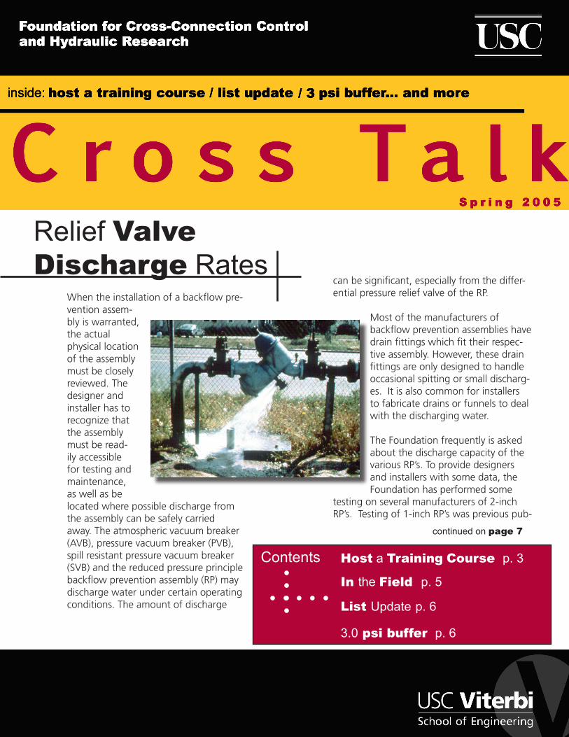
When the installation of a backflow pre-vention assem-bly is warranted, the actual physical location of the assembly must be closely reviewed. The designer and installer has to recognize that the assembly must be read-ily accessible for testing and maintenance, as well as be located where possible discharge from the assembly can be safely carried away. The atmospheric vacuum breaker (AVB), pressure vacuum breaker (PVB), spill resistant pressure vacuum breaker (SVB) and the reduced pressure principle backflow prevention assembly (RP) may discharge water under certain operating conditions. The amount of discharge
Contents
In the Field p. 5
Host a Training Course p. 3
3.0 psi buffer p. 6
Relief Valve Discharge Rates
can be significant, especially from the differ-ential pressure relief valve of the RP.
Most of the manufacturers of backflow prevention assemblies have drain fittings which fit their respec-tive assembly. However, these drain fittings are only designed to handle occasional spitting or small discharg-es. It is also common for installers to fabricate drains or funnels to deal with the discharging water. The Foundation frequently is asked about the discharge capacity of the various RP’s. To provide designers and installers with some data, the Foundation has performed some
testing on several manufacturers of 2-inch RP’s. Testing of 1-inch RP’s was previous pub-
continued on page 7
List Update p. 6
FoundationMembership
The Foundation’s Membership Program provides many benefits to the Members of the Foundation. These include: a twenty-five percent discount on manuals, twenty percent dis-count on Foundation Training Courses for any employee of the Member company/organi-zation, the List of Approved Backflow Prevention Assemblies, printed quarterly, and access to the up-to-the-minute version of the List for those Members with Internet access.
Members are encouraged to call the Foundation with technical questions. The Founda-tion’s Engineering Staff is available to assist members with the various aspects of field testing backflow preventers, installing backflow preventers and administering their cross-connection control program.
Many consider their Membership with the Foundation one of their best forms of insurance to protect the agency from liability involved when a distribution system becomes contami-nated or polluted through cross-connections. Membership in the Foundation helps to provide the tools needed to effectively initiate and run a cross-connection control program.
Below is a list of those who have become members of the Foundation this past quarter:
A & A Active Backflow
Anheuser-Busch
ARS Plumbing
Backflow Prevention, Inc.
Backflow Preventions
Breeden Mechanical, Inc.
C & L Rooter Service
Calenergy
County of Ventura
Drain Tech, Inc.
Glendale Water & Power
Hazen and Sawyer, P.C.
Cross Talk SPRING 2005 Page 2
Knight Piesold
Langley, City of
Laramie, City of
Los Alamos County
Lyon County Utilities
Marine Corps Base- Camp Pendleton
Petersburg Water Utility
Poweshiek Water Association
RD Loeb, Inc.
Rogue Valley Backflow Service
Tommy Disario, Jr.
Western HVAC
Cross Talk is published by the Foundation for Cross-Connection Control and Hydraulic Research at the
University of Southern California for Foundation Members. Limited additional copies are available to Members upon rquest.
2005 © University of Southern California. All rights reserved.
Cross Talk SPRING 2005 Page 3
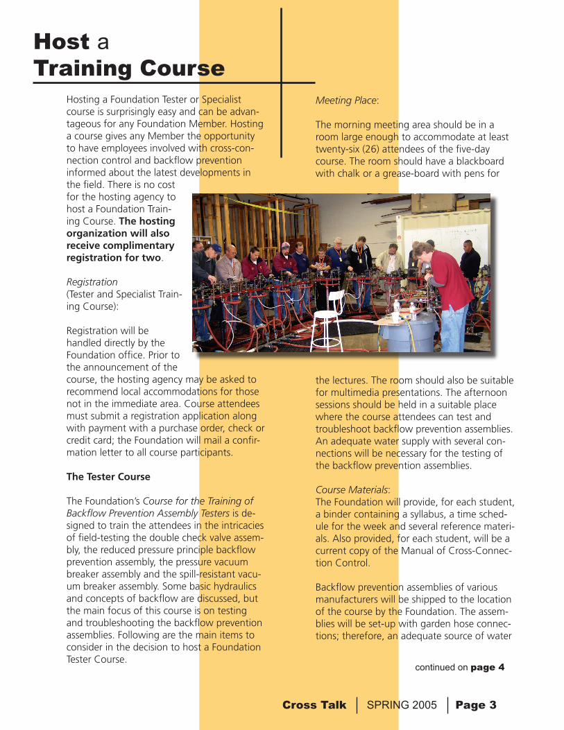
Hosting a Foundation Tester or Specialist course is surprisingly easy and can be advan-tageous for any Foundation Member. Hosting a course gives any Member the opportunity to have employees involved with cross-con-nection control and backflow prevention informed about the latest developments in the field. There is no cost for the hosting agency to host a Foundation Train-ing Course. The hosting organization will also receive complimentary registration for two.
Registration (Tester and Specialist Train-ing Course):
Registration will be handled directly by the Foundation office. Prior to the announcement of the course, the hosting agency may be asked to recommend local accommodations for those not in the immediate area. Course attendees must submit a registration application along with payment with a purchase order, check or credit card; the Foundation will mail a confir-mation letter to all course participants.
The Tester Course
The Foundation’s Course for the Training of Backflow Prevention Assembly Testers is de-signed to train the attendees in the intricacies of field-testing the double check valve assem-bly, the reduced pressure principle backflow prevention assembly, the pressure vacuum breaker assembly and the spill-resistant vacu-um breaker assembly. Some basic hydraulics and concepts of backflow are discussed, but the main focus of this course is on testing and troubleshooting the backflow prevention assemblies. Following are the main items to consider in the decision to host a Foundation Tester Course.
Host a Training Course
Meeting Place:
The morning meeting area should be in a room large enough to accommodate at least twenty-six (26) attendees of the five-day course. The room should have a blackboard with chalk or a grease-board with pens for
the lectures. The room should also be suitable for multimedia presentations. The afternoon sessions should be held in a suitable place where the course attendees can test and troubleshoot backflow prevention assemblies. An adequate water supply with several con-nections will be necessary for the testing of the backflow prevention assemblies.
Course Materials:The Foundation will provide, for each student, a binder containing a syllabus, a time sched-ule for the week and several reference materi-als. Also provided, for each student, will be a current copy of the Manual of Cross-Connec-tion Control.
Backflow prevention assemblies of various manufacturers will be shipped to the location of the course by the Foundation. The assem-blies will be set-up with garden hose connec-tions; therefore, an adequate source of water
continued on page 4
Host a Training Coursecontinued from page 3
Cross Talk SPRING 2005 Page 4
will be necessary. In addition, tools and gages will be provided by the Foundation.
The Foundation will provide a ‘‘certificate of completion’’ for each member of the class who successfully completes the writ-ten and performance portions of the final examination.
The Specialist Course
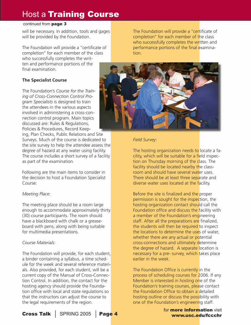
The Foundation’s Course for the Train-ing of Cross-Connection Control Pro-gram Specialists is designed to train the attendees in the various aspects involved in administering a cross-con-nection control program. Main topics discussed are: Rules & Regulations, Policies & Procedures, Record Keep-ing, Plan Checks, Public Relations and Site Surveys. Much of the course is dedicated to the site survey to help the attendee assess the degree of hazard at any water using facility. The course includes a short survey of a facility as part of the examination.
Following are the main items to consider in the decision to host a Foundation Specialist Course:
Meeting Place:
The meeting place should be a room large enough to accommodate approximately thirty (30) course participants. The room should have a blackboard with chalk or a grease-board with pens, along with being suitable for multimedia presentations.
Course Materials:
The Foundation will provide, for each student, a binder containing a syllabus, a time sched-ule for the week and several reference materi-als. Also provided, for each student, will be a current copy of the Manual of Cross-Connec-tion Control. In addition, the contact for the hosting agency should provide the Founda-tion office with local and state regulations so that the instructors can adjust the course to the legal requirements of the region.
The Foundation will provide a ‘‘certificate of completion’’ for each member of the class who successfully completes the written and performance portions of the final examina-tion.
Field Survey:
The hosting organization needs to locate a fa-cility, which will be suitable for a field inspec-tion on Thursday morning of the class. The facility should be located nearby the class-room and should have several water uses. There should be at least three separate and diverse water uses located at the facility.
Before the site is finalized and the proper permission is sought for the inspection, the hosting organization contact should call the Foundation office and discuss the facility with a member of the Foundation’s engineering staff. After all the preparations are finalized, the students will then be required to inspect the locations to determine the uses of water, whether there are any actual or potential cross-connections and ultimately determine the degree of hazard. A separate location is necessary for a pre- survey, which takes place earlier in the week.
The Foundation Office is currently in the process of scheduling courses for 2006. If any Member is interested in hosting one of the Foundation’s training courses, please contact the Foundation Office to obtain a detailed hosting outline or discuss the possibility with one of the Foundation’s engineering staff.
for more information visitwww.usc.edu/fccchr
Cross Talk SPRING 2005 Page 5
O-Rings Together
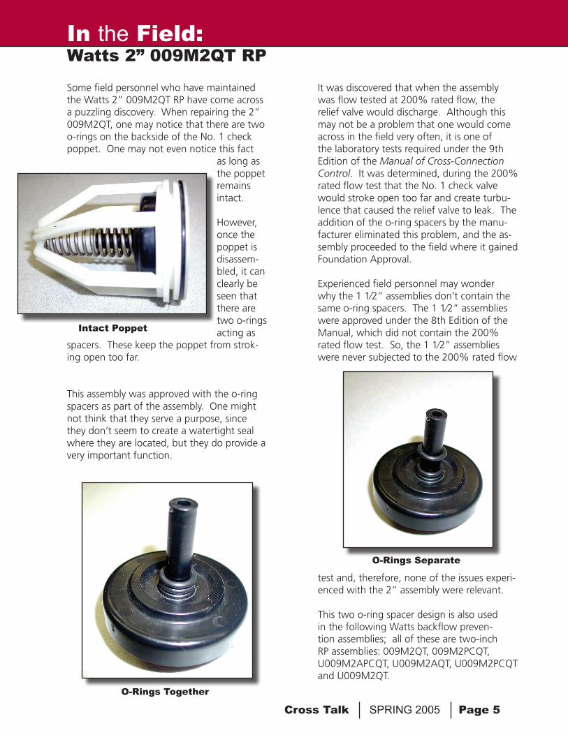
Some field personnel who have maintained the Watts 2” 009M2QT RP have come across a puzzling discovery. When repairing the 2” 009M2QT, one may notice that there are two o-rings on the backside of the No. 1 check poppet. One may not even notice this fact
as long as the poppet remains intact. However, once the poppet is disassem-bled, it can clearly be seen that there are two o-rings acting as
spacers. These keep the poppet from strok-ing open too far.
This assembly was approved with the o-ring spacers as part of the assembly. One might not think that they serve a purpose, since they don’t seem to create a watertight seal where they are located, but they do provide a very important function.
It was discovered that when the assembly was flow tested at 200% rated flow, the relief valve would discharge. Although this may not be a problem that one would come across in the field very often, it is one of the laboratory tests required under the 9th Edition of the Manual of Cross-Connection Control. It was determined, during the 200% rated flow test that the No. 1 check valve would stroke open too far and create turbu-lence that caused the relief valve to leak. The addition of the o-ring spacers by the manu-facturer eliminated this problem, and the as-sembly proceeded to the field where it gained Foundation Approval.
Experienced field personnel may wonder why the 1 1⁄2” assemblies don’t contain the same o-ring spacers. The 1 1⁄2” assemblies were approved under the 8th Edition of the Manual, which did not contain the 200% rated flow test. So, the 1 1⁄2” assemblies were never subjected to the 200% rated flow
test and, therefore, none of the issues experi-enced with the 2” assembly were relevant.
This two o-ring spacer design is also used in the following Watts backflow preven-tion assemblies; all of these are two-inch RP assemblies: 009M2QT, 009M2PCQT, U009M2APCQT, U009M2AQT, U009M2PCQT and U009M2QT.
In the Field: Watts 2” 009M2QT RP
O-Rings Separate
Intact Poppet
Cross Talk SPRING 2005 Page 6
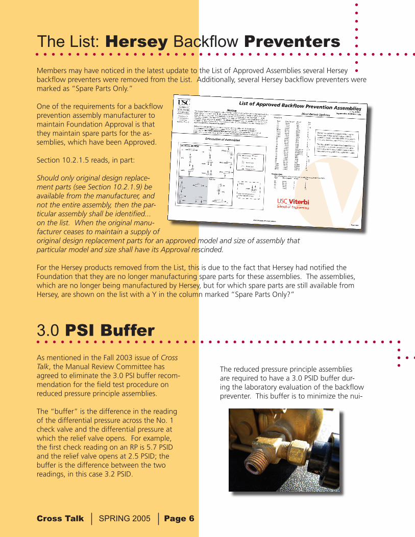
Members may have noticed in the latest update to the List of Approved Assemblies several Hersey backflow preventers were removed from the List. Additionally, several Hersey backflow preventers were marked as “Spare Parts Only.”
One of the requirements for a backflow prevention assembly manufacturer to maintain Foundation Approval is that they maintain spare parts for the as-semblies, which have been Approved.
Section 10.2.1.5 reads, in part:
Should only original design replace-ment parts (see Section 10.2.1.9) be available from the manufacturer, and not the entire assembly, then the par-ticular assembly shall be identified...on the list. When the original manu-facturer ceases to maintain a supply of original design replacement parts for an approved model and size of assembly that particular model and size shall have its Approval rescinded.
For the Hersey products removed from the List, this is due to the fact that Hersey had notified the Foundation that they are no longer manufacturing spare parts for these assemblies. The assemblies, which are no longer being manufactured by Hersey, but for which spare parts are still available from Hersey, are shown on the list with a Y in the column marked “Spare Parts Only?”
The List: Hersey Backflow Preventers
As mentioned in the Fall 2003 issue of Cross Talk, the Manual Review Committee has agreed to eliminate the 3.0 PSI buffer recom-mendation for the field test procedure on reduced pressure principle assemblies.
The “buffer” is the difference in the reading of the differential pressure across the No. 1 check valve and the differential pressure at which the relief valve opens. For example, the first check reading on an RP is 5.7 PSID and the relief valve opens at 2.5 PSID; the buffer is the difference between the two readings, in this case 3.2 PSID.
The reduced pressure principle assemblies are required to have a 3.0 PSID buffer dur-ing the laboratory evaluation of the backflow preventer. This buffer is to minimize the nui-
3.0 PSI Buffer
Cross Talk SPRING 2005 Page 7
Relief Valve Discharge Ratescontinued from page 1
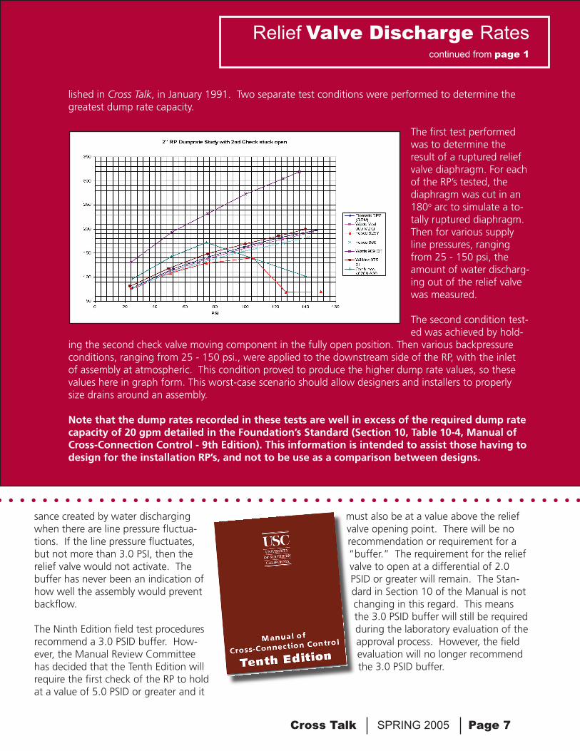
lished in Cross Talk, in January 1991. Two separate test conditions were performed to determine the greatest dump rate capacity.
The first test performed was to determine the result of a ruptured relief valve diaphragm. For each of the RP’s tested, the diaphragm was cut in an 180o arc to simulate a to-tally ruptured diaphragm. Then for various supply line pressures, ranging from 25 - 150 psi, the amount of water discharg-ing out of the relief valve was measured. The second condition test-ed was achieved by hold-
ing the second check valve moving component in the fully open position. Then various backpressure conditions, ranging from 25 - 150 psi., were applied to the downstream side of the RP, with the inlet of assembly at atmospheric. This condition proved to produce the higher dump rate values, so these values here in graph form. This worst-case scenario should allow designers and installers to properly size drains around an assembly.
Note that the dump rates recorded in these tests are well in excess of the required dump rate capacity of 20 gpm detailed in the Foundation’s Standard (Section 10, Table 10-4, Manual of Cross-Connection Control - 9th Edition). This information is intended to assist those having to design for the installation RP’s, and not to be use as a comparison between designs.
sance created by water discharging when there are line pressure fluctua-tions. If the line pressure fluctuates, but not more than 3.0 PSI, then the relief valve would not activate. The buffer has never been an indication of how well the assembly would prevent backflow.
The Ninth Edition field test procedures recommend a 3.0 PSID buffer. How-ever, the Manual Review Committee has decided that the Tenth Edition will require the first check of the RP to hold at a value of 5.0 PSID or greater and it
must also be at a value above the relief valve opening point. There will be no recommendation or requirement for a “buffer.” The requirement for the relief valve to open at a differential of 2.0 PSID or greater will remain. The Stan-dard in Section 10 of the Manual is not changing in this regard. This means the 3.0 PSID buffer will still be required during the laboratory evaluation of the approval process. However, the field evaluation will no longer recommend the 3.0 PSID buffer.
Foundation for Cross-ConnectionControl and Hydraulic Research
University of Southern CaliforniaKaprielian Hall 200Los Angeles, California 90089-2531
First ClassUS Postage PAID
University of Southern California
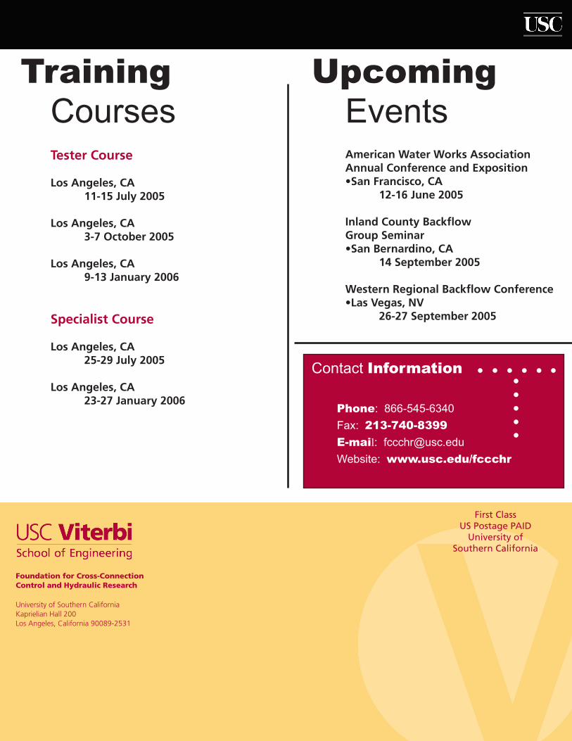
TrainingCourses
UpcomingEvents
Tester Course
Los Angeles, CA 11-15 July 2005
Los Angeles, CA 3-7 October 2005
Los Angeles, CA 9-13 January 2006
Specialist Course
Los Angeles, CA 25-29 July 2005
Los Angeles, CA 23-27 January 2006
American Water Works AssociationAnnual Conference and Exposition•San Francisco, CA 12-16 June 2005
Inland County Backflow Group Seminar•San Bernardino, CA 14 September 2005
Western Regional Backflow Conference•Las Vegas, NV 26-27 September 2005
Contact Information
Phone: 866-545-6340
Fax: 213-740-8399
E-mail: [email protected]
Website: www.usc.edu/fccchr