Embed Size (px)
Citation preview

KOLEJ UNIVERSITI TEKNOLOGI TUN HUSSEIN ONN
I' III BORANG PENGESAHAN STATUS TESIS~ I II I JUDUL: FABRICATION, CHARACTERIZATION, AND OPTIMIZATION OF II I IN-HOUSE MOSFET TRANSISTOR USING SPIN ON DOPANT TECHNIOUE I :.
I I I I I
I I I I
SES! PENGAID.-N: 2004/2005
Saya M..A R.LIA HINT! MORSTN (HURUF BESA...R)
mengaku membenarkan tesis (-I2SM1 Satjanal Doktor Falsafflh)* ini disimpan di Perpustakal1n dengan syarl1t-syarat kegunaan seperti berikut:
1. 2. 3.
4.
Tesis adalah haIanilik Kolej Universiti Telcnologi Tun Hussein Onn. Perpustakaan dibenarkan membuat salinan untuk tujuan pengajian sahaja.s Perpustakaan dibenarkan membuat salinan tesis ini sebagai ballan pertukaran antara institusi pengajian tinggi. **Sila tandakan (..J) o SULIT
liTll TERHAD ,L..J,
o TIDAK TERHAD
(Mengandungi maklumat yang berdrujah keselamatan atau kepentingan Malaysia seperti yang termah."tub di dalam AKT A RAHSIA RASMI 1972)
CMengandungi maklumat 1ERHAD yang teiah ditentukan oleh organisasi! badan di mana penydidikan dijalankan
Disahkan oleh
(T TANGAN PENULIS)
Alamat Tetap: PROF. DR. HASHIM BIN SAlM No.1, Jalan Bukit, Bukit Batu, 81020 Kuiai, Jonor.
(Nama Penyelia)
Tarikh: 2. NOVErnBER 2004 Tarikh: 2 NOVEl\ffiER 2004
CATATAN: * Potong yang tidak berkenaan. ** Jika tesis ini SULIT atau 1ERHAD, sila lampirkan surat daripada pihak berkuasa
organisasi berkenaan dengan menyetakan sekali sebab dan tempoh tesis ini perlu dikeiaskan sebagai Su"LIT atau TERHAD .
• Tesis dimaksudkan sebagai tesis bagi Ijazah Dol-ior Falsafah dan Sarjana secara penyelidikan, atau disertasi bagi pengajian secara keIja h.llrsus dan penyelididikan, at au Laporan Projek Sa(;ana Muda (pSM).
II II II II II I II II II II II II II I
II II I I I I I I I
SIGNATURE
SUPERVISOR I
DATE
SIGNATURE
SUPERVISOR II
DATE
"This thesis has been read and certified by".
~~~~~~~~~~~~~ 2 NOVEMBER 2004
ASSOCIATE PROFESSOR DR. UDA BIN HASHIM
2 NOVEMBER 2004
FABRICATION, CHARACTERIZATION AND OPTIMIZATION OF IN-HOUSE
MOSFET TRANSISTOR USING SPIN ON DOPANT TECHNIQUE
MARLIA BINTI MORSIN
This thesis is submitted in partial to fulfillment of the requirement for the
Master of Electrical Engineering
Faculty of Electrical and Electronic Engineering
Tun Hussien ann University College of Technology
NOVEMBER, 2004
11
"Hereby, I declare that this thesis entitled "Fabrication, Characterization, and
Optimization of In-House MOSFET Transistor using Spin - On Dopant Technique" is a
result of my own research and idea except for the work that has been clearly cited in the
references".
SIGNATURE
NAME
DATE
1l;;~/J)JJ7p .... f:?.:f.~.~ ....................... . MARLIA BINTI MORSIN
2 NOVEMBER 2004
To Mak and Ayah; for your love and support
My bros a11d sis, together we fight and reach the top
Andfor me ... one step closer to hit
1Il
v
ABSTRACT
This thesis explains the development and fabrication of first in-house MOSFET device
using spin -on dopant technique at KUKUM Microfahrication Cleanroom. The process
started with the establishment of process flow, process modules, and process parameters.
Four modules were developed. The characteristics prior to the MOSFET device
fabrication namely dry and wet oxidation, etching, resist thiclrness, exposure dose
optimization, n-type and p-type spin on dopant and diffusion and also metal thiclrness
characterization were recorded. The data were analyzed and applied in the fabrication of
MOSFET devices. The MOSFET fabrication process llsed blanket-field oxide for
isolation, positive resist for lithography process, Boron and Phosphorus for source/drain
doping and aluminum for metallization. The whole MOSFET process had fOllT masking
process specifically source/drain masking, gate masking, contact masking, and metal
masking. The result for each processes are presented in this thesis.
VI
ABSTRAK
Tesis ini menerangkan mengenai pembangunan modul dan proses fabrikasi peranti
MOSFET yang pertama dibina menggunakan teknik "spin -on dopant" di Bilik Bersih,
Makmal Mikrofabrikasi, KUKUM. Proses ini bermula dengan membangunkan aliran
proses fabrikasi, modul proses and mengenalpasti paramater- parameter yang terlibat.
Empat modul telah dibangunkan sebelum proses fabrikasi peranti MOSFET iaitu
pengoksidaan basah dan leering serta puna ran, ketebalan rintang foto dan
pengoptimuman dos dedahan, resapan jenis n dan jenis p serta penglogaman. Setiap data
dianalisa dan hasilnya digunakan di dalam proses fabrikasi MOSFET. Proses fabrikasi
MOSFET menggunakan pengoksidaan selimut - mednn untuk pengasingan transistor,
rintang foto positifbagi proses lithografi, boron dan fosforan sebagai dopan untuk proses
resapan dan aluminum bagi proses penglogaman. Keselumhan proses ini melibatkan
empat jenis topeng ; topeng telaga (salir dan sumber), topeng get, top eng tingkap
senhlhan dan topeng logam. Basil bagi setiap proses dinyatakan di dalam tesis ini.
ACKNO\\'LEDGEMENT
First of all, I would like to thank my project supervisors, Prof. Dr. Hashim bin
Saim and Ass. Prof. Dr. Uda bin Hashim for providing me guidance and dedications to
carry out this project.
I would like to express my sincere gratitude to Nurhamidah, Teaching Engineer
and all staffs at School of Microelectronic Engineering, KUKUM and not forgotten to
all staffs at Pusat Pengajian Siswazah, KUiTTHO for their valuable contribution and
help.
Lastly, to all my beloved friends who were involved in this project whether
directly or indirectly. Special thanks for all of you.
IV
VI
CONTENTS
CHAPTER TITLE PAGE
TITLE
DECLARATION 11
DEDICATION 11I
ACKNOWLEDGEMENT IV
ABSTRACT v
ABSTRAK VI
TABLE OF CONTENT V11
LIST OF TABLES Xl
LIST OF FIGURES XlI
LIST OF SYMBOL XVI
LIST OF APPENDIX xviii
I PROJECT OVERVIEW
1.1 Overview
1.2 Introduction 1
1.3 Project Aspire 5
1.4 Objective 5
1.5 Project Scope 6
1.6 Project Workflow 6
V11
1.7 Importance of the Project 7
II LITERATURE REVIEW - MOSFET TRANSISTOR 9
2.1 Overview 9
2.2 Introduction 9
2.3 MOSFET Device 12
2.4 P- Channel MOSFET (PMOS) 13
2.4.1 Structure ofP-Channel MOS (PMOS) 14
Transistor
2.4.2 A Qualitative Description ofP - Channel MOS 16
( PMOS) Transistor Operation
2.5 N- Channel MOSFET (NMOS) 19
2.5.1 Structure ofN-Channel MOS (NMOS) 19
Transistor
2.5.2 A Qualitative Description ofN - Channel 20
MOS
( NMOS) Transistor Operation
2.6 Geometric and material properties of aMOS 23
transistor
2.6.1 The gate capacitance 25
2.6.2 Mobility of carriers 25
2.6.3 DC analysis of the PMOS transistors 26
2.6.3.1 Current-Voltage relationships 26
ill LITERATURE REVIEW - FABRICA nON PROCESS 28
3.1 Overview 28
3.2 Introduction 28
3.3 Wafer Preparation 29
3.3.1 Doping Semiconductor 31
3.4 Clean Process 33
VllI
3.4.1 Wet Cleaning Process 34
3.4.2 Contaminants 35
3.5 Thermal Process 35
3.5.1 Oxidation 35
3.5.1.1 Oxide Measurements 39
3.5.2 Diffusion 40
3.5.2.1 Deposition and Drive-In 45
3.5.2.2 Doping Measurement 45
3.6 Photolithography 47
3.6.1 Photoresist Coating 48
3.6.1.1 Photoresist 49
3.6.2 Soft Bake 51
3.6.3 Alignment and Exposure 52
3.6.3.1 Exposure source 52
3.6.4 Development 53
3.6.5 HardBake 54
3.6.6 Pattern Inspection 54
3.7 Etching 55
3.7.1 Wet Etch Process 56
3.7.1.1 Oxide Wet Etch 57
3.7.1.2 Metal Etch 58
3.7.2 Etch Basics 59
3.7.2.1 Etch Rate 59
3.7.2.2 Uniformity 59
3.8 Metallization 60
3.8.1 Aluminum 61
3.8.2 Physical Vapor Deposition (PVD) 62
3.8.2.1 Thennal Evaporation 62
3.8.2.2 Thickness Measurement 64
3.9 Characterization 65
IV
V
VI
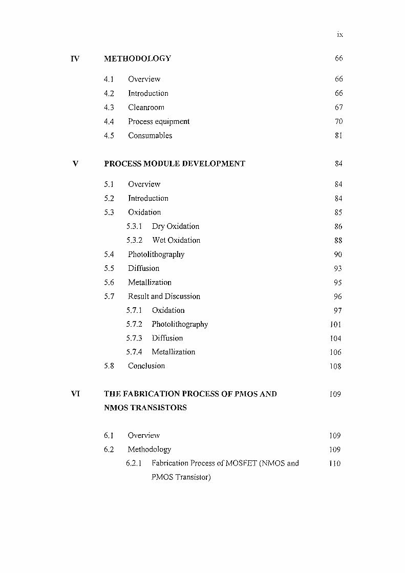
METHODOLOGY
4.1 Overview
4.2 Introduction
4.3 Cleanroom
4.4 Process equipment
4.5 Consumables
PROCESS MODULE DEVELOPMENT
5.1 Overview
5.2 Introduction
5.3 Oxidation
5.3.1 Dry Oxidation
5.3.2 Wet Oxidation
5.4 Photolithography
5.5 Diffusion
5.6 Metallizati on
5.7 Result and Discussion
5.7.1 Oxidation
5.7.2 Photolithography
5.7.3 Diffusion
5.7.4 Metallization
5.8 Conclusion
THE FABRICATION PROCESS OF PMOS AND
NMOS TRANSISTORS
IX
66
66
66
67
70
81
84
84
84
85
86
88
90
93
95
96
97
101
104
106
108
109
6.1 Overview 109
6.2 Methodology 109
6.2.1 Fabrication Process ofMOSFET (1\TMOS and 110
PMOS Transistor)
x
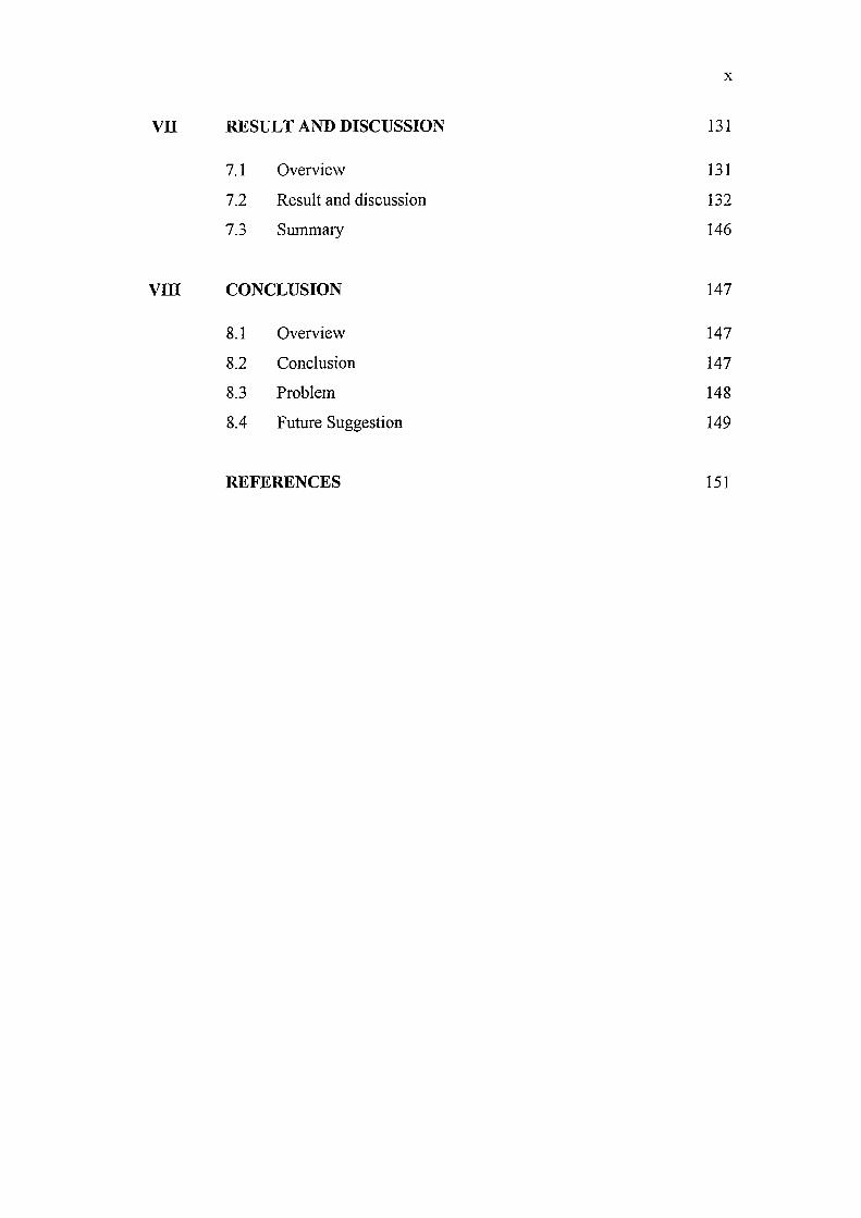
vn RESULT AND DISCUSSION 131
7.1 Overview 131
7.2 Result and discussion 132
7.3 Summary 146
VllI CONCLUSION 147
8.1 Overview 147
8.2 Conclusion 147
8.3 Problem 148
8.4 Future Suggestion 149
REFERENCES 151
V111
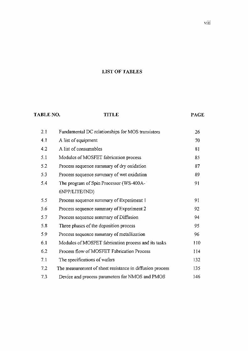
LIST OF TABLES
TABLE NO. TITLE PAGE
2.1 Fundamental DCrelationships for MOS transistors 26
4.1 A list of equipment 70
4.2 A list of consumables 81
5.1 Modules ofMOSFET fabrication process 85
5.2 Process sequence summary of dry oxidation 87
5.3 Process sequence summary of wet oxidation 89
5.4 The program of Spin Processor (WS-400A- . 91
6NPP ILlTEIIND)
5.5 Process sequence summary of Experiment 1 91
5.6 Process sequence summary of Experiment 2 92
5.7 Process sequence summary of Diffusion 94
5.8 Three phases of the deposition process 95
5.9 Process sequence summary of metallization 96
6.1 Modules ofMOSFET fabrication process and its tasks 110
6.2 Process flow ofMOSFET Fabrication Process 114
7.1 The specifications of wafers 132
7.2 The measurement of sheet resistance in diffusion process 135
7.3 Device and process parameters for NMOS and PMOS 146
XII
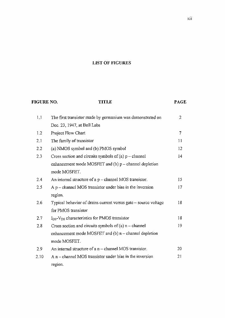
LIST OF FIGURES
FIGURE NO. TITLE PAGE
1.1 The first transistor made by germanium was demonstrated on 2
Dec. 23, 1947, at Bell Labs
1.2 Project Flow Chart 7
2.1 The family of transistor 11
2.2 (a) NMOS symbol and (b) PMOS symbol 12
2.3 Cross section and circuits symbols of (a) p - channel 14
enhancement mode MOSFET and (b) p - channel depletion
mode MOSFET.
2.4 An internal structure of a p - channel MOS transistor. 15
2.5 A P - channel MOS transistor under bias in the inversion 17
region.
2.6 Typical behavior of drains current versus gate - source voltage 18
for PMOS transistor
2.7 IDs-VDs characteristics for PMOS transistor 18
2.8 Cross section and circuits symbols of (a) n - channel 19
enhancement mode MOSFET and (b) n - channel depletion
mode MOSFET.
2.9 An internal structure of a n - channel MOS transistor. 20
2.10 An - channel MOS transistor under bias in the inversion 21
region.
XlJI
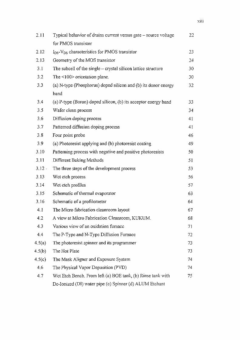
2.11 Typical behavior of drains current versus gate - source voltage 22
for PMOS transistor
2.12 10s-Vos characteristics for PMOS transistor ," _.:l
2.13 Geometry of the MOS transistor 24
3.1 The subcell of the single - crystal silicon lattice structure 30
3.2 The <100> orientation plane. 30
3.3 (a) N-type (Phosphorus) doped silicon and (b) its donor energy 32
band
3.4 (a) P-type (Boron) doped silicon, (b) its acceptor energy band 33
3.5 Wafer clean process 34
3.6 Diffusion doping process 41
3.7 Patterned diffusion doping process 41
3.8 F our point probe 46
3.9 (a) Photoresist applying and (b) photoresist coating 49
3.10 Patterning process with negative and positive photoresists 50
3.11 Different Baking Methods 51
3.12 . The three steps of the development process 53
3.13 Wet etch process 56
3.14 Wet etch profiles 57
3.15 Schematic of thermal evaporator 63
3.16 Schematic of a profilometer 64
4.1 The Micro fabrication cleanroom layout 67
4.2 A view at Micro Fabrication Cleanroom, KUKUM. 68
4.3 Various view of an oxidation furnace 71
4.4 The P-Type and N-Type Diffusion Furnace 72
4.5(a) The photoresist spinner and its programmer 73
4.5(b) The Hot Plate 73
4.5(c) The Mask Aligner and Exposure System 74
4.6 The Physical Vapor Deposition (PVD) 74
4.7 Wet Etch Bench. From left (a) BOE tank, (b) Rinse tank with 75
De-Ionized (DI) water pipe (c) Spinner (d) ALUM Etchant
XIV
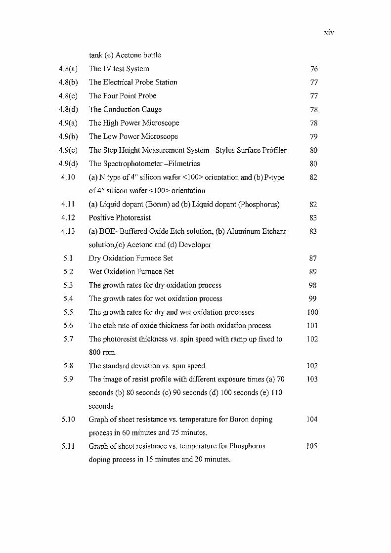
tank (e) Acetone bottle
4.8(a) The IV test System 76
4.8(b) The Electrical Probe Station 77
4.8(c) The Four Point Probe 77
4.8(d) The Conduction Gauge 78
4.9(a) The High Power Microscope 78
4.9(b) The Low Power Microscope 79
4.9(c) The Step Height Measurement System -Stylus Surface Profiler 80
4.9(d) The Spectrophotometer -Filmetrics 80
4.10 (a) N type of 4" silicon wafer <100> orientation and (b) P-type 82
of 4" silicon wafer <100> orientation
4.11 (a) Liquid dopant (Boron) ad (b) Liquid dopant (Phosphorus) 82
4.12 Positive Photoresist 83
4.13 (a) BOE- Buffered Oxide Etch solution, (b) Aluminum Etchant 83
solution,( c) Acetone and (d) Developer
5.1 Dry Oxidation Furnace Set 87
5.2 Wet Oxidation Furnace Set 89
5.3 The growth rates for dry oxidation process 98
5.4 The growth rates for wet oxidation process 99
5.5 The growth rates for dry and wet oxidation processes 100
5.6 The etch rate of oxide thickness for both oxidation process 101
5.7 The photoresist thickness vs. spin speed with ramp up fixed to 102
800 rpm.
5.8 The standard deviation vs. spin speed. 102
5.9 The image of resist profile with different exposure times (a) 70 103
seconds (b) 80 seconds (c) 90 seconds (d) 100 seconds (e) 110
seconds
5.10 Graph of sheet resistance vs. temperature for Boron doping 104
process in 60 minutes and 75 minutes.
5.11 Graph of sheet resistance vs. temperature for Phosphorus 105
doping process in 15 minutes and 20 minutes.
x'V
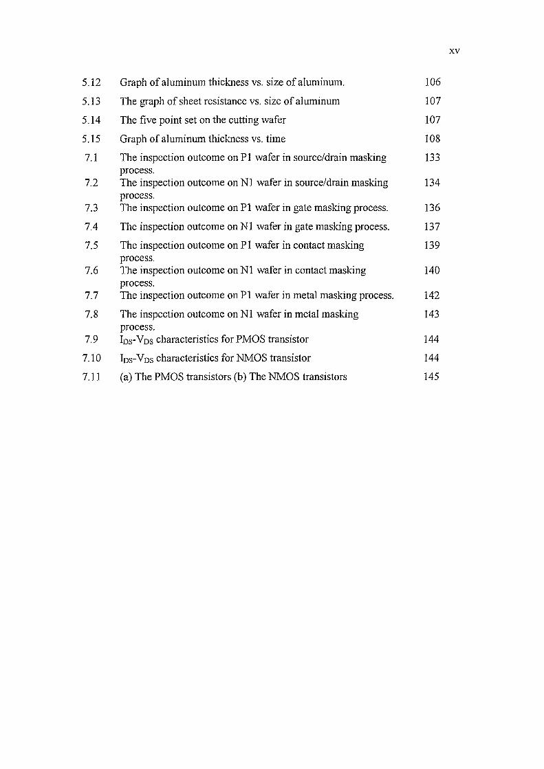
5.12 Graph of aluminum thickness vs. size of aluminum. 106
5.13 The graph of sheet resistance vs. size of aluminum 107
5.14 The five point set on the cutting wafer 107
5.15 Graph of aluminum thickness vs. time 108
7.1 The inspection outcome on PI wafer in source/drain masking 133 process.
7.2 The inspection outcome on Nl wafer in source/drain masking 134 process.
7.3 The inspection outcome on PI wafer in gate masking process. 136
7.4 The inspection outcome on N1 wafer in gate masking process. 137
7.5 The inspection outcome on PI wafer in contact masking 139 process.
7.6 The inspection outcome on Nl wafer in contact masking 140 process.
7.7 The inspection outcome on PI wafer in metal masking process. 142
7.8 The inspection outcome on N1 wafer in metal masking 143 process.
7.9 Ios-Vos characteristics for PMOS transistor 144
7.10 Ios-Vos characteristics for NMOS transistor 144
7.11 (a) The PMOS transistors (b) The NMOS transistors 145
a
A
A B
J3 c
D
D
In
MOSFET
LIST OF SYMBOL
Lattice parameter
Constant in oxidation law
Symbol for lO-IOcm or 1O-8m
Constant in oxidation law
Linear gain
Capacitance per unit area
Oxide capacitance per unit area
A dopant (chemical equation only)
Diffusion coefficient
Transconductance
Planck's constant
Current
Body current
Drain current
Gate current
Source current
Flux
Boltzmann's constant
Segregation coefficient
A length
Mass
Metal Oxide Semiconductor Field Effect Transistor
XVI
XVII
NMOS N- Channel Metal Oxide Semiconductor
PMOS P- Channel Metal Oxide Semiconductor
q Charge on the electron
Q Charge per unit area
t Time
tax Oxide thickness
VB Body voltage
VD Drain voltage
VDs Drain - Source Voltage
VG Gate voltage
VGS Gate-Source Voltage
VTH Threshold voltage
T1f Work function of metal
Xi Initial oxide thickness
Xj Junction depth
Xo Thickness of oxide film
X Property of material
C Permittivity
Co Permittivity of free space
cox Permittivity of silicon dioxide
JI Mobility
Jln Electron mobility
Jlp Hole mobility
P Charge distribution
P Resistivity
ps Sheet resistivity
Rs Sheet resistance
Q Symbol for ohms
LIST OF APPENDIX
APPENDIX NO. TITLE
A The first PMOS and NMOS fabrication process
B
C
Process Module Development
Fabrication process of PMOS and NMOS transistors
XVIII
PAGE
4
28
CHAPTER I
PROJECT OVERVIE'"
1.1 Overview
This chapter will explain the project overview including objective, scopes, and
methodology of project.
1.2 Introduction
The rise ofMOS technology is a classic study since it is the most important
devices in electronic industry [1] due to its capability. This project is stressed on the
fabrication, characterization, and optimization of in-house MOSFET devices. In order to
fabricate the devices, the process module development was established and formed
backbone of this project.