Embed Size (px)
Citation preview
September 2005
Linear Encodersfor Numerically Controlled Machine Tools
2
Further information is available on the Internet at www.heidenhain.de as well as upon request.
Product brochures:Exposed Linear EncodersAngle EncodersRotary EncodersHEIDENHAIN subsequent electronicsHEIDENHAIN controlsMeasuring Systems for Machine Tool Inspection and Acceptance Testing
Technical Information brochures:Accuracy of Feed AxesSealed Linear Encoders with Single-Field ScanningEnDat 2.2 – Bidirectional Interface for Position EncodersEncoders for Direct Drives
••••••
••
•
•
This catalog supersedes all previous editions, which thereby become invalid.The basis for ordering from HEIDENHAIN is always the catalog edition valid when the contract is made.
Standards (ISO, EN, etc.) apply only where explicitly stated in the catalog.
DIADUR and AURODUR are registered trademarks ofDR. JOHANNES HEIDENHAIN GmbH, Traunreut.

Overview
Linear Encoders 4
Selection Guide 6
Technical Features and Mounting Information
Measuring Principles Measuring standard 8
Absolute measuring method 8
Incremental measuring method 9
Photoelectric scanning 10
Measuring Accuracy 12
Mounting and Mechanical Design Types 14
General Mechanical Information 17
Specifi cations Recommended measuring Linear encoder step for positioning Series or Model
For absolute position measurement to 0.1 µm LC 400 Series 18
LC 100 Series 20
For incremental linear measurement with very high repeatability
to 0.1 µm LF 481 22
LF 183 24
For incremental linear measurement to 0.5 µm LS 487 26
LS 187 28
For incremental linear measurementfor large measuring lengths
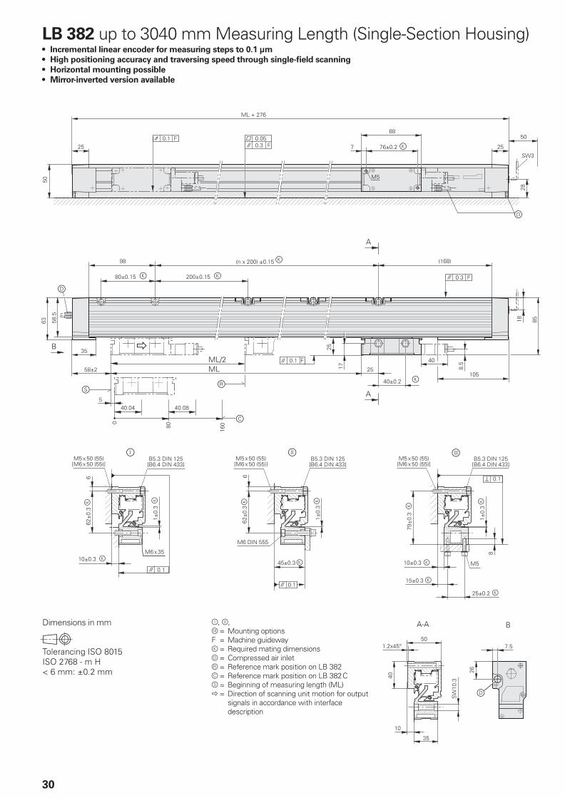
to 0.1 µm LB 382 – Single-Section 30
LB 382 – Multi-Section 32
Electrical Connection
Incremental Signals »1 VPP 34
Absolute Position Values EnDat 36
Fanuc and Mitsubishi 43
Connecting Elements and Cables 44
General Electrical Information 48
Evaluation Electronics 50
HEIDENHAIN Measuring Equipment 51
Content

4
Linear Encoders for NC-Controlled Machine Tools
Linear encoders from HEIDENHAIN for NC-controlled machine tools can be used nearly everywhere. They are ideal for machines and other equipment whose feed axes are in a closed loop, such as milling machines, machining centers, boring machines, lathes and grinding machines. The benefi cial dynamic behavior of the linear encoders, their highly reliable traversing speed, and their acceleration in the direction of measurement predestine them for use on highly-dynamic conventional axes as well as on direct drives.
HEIDENHAIN also supplies linear encoders for other applications, such as
Manual machine toolsPresses and bending machinesAutomation and production equipment
Please request further documentation, or inform yourself on the Internet at www.heidenhain.de.
•••
Advantages of linear encoders
Linear encoders measure the position of linear axes without additional mechanical transfer elements. The control loop for position control with a linear encoder also includes the entire feed mechanics. Transfer errors from the mechanics can be detected by the linear encoder on the slide, and corrected by the control electronics. This can eliminate a number of potential error sources:
Positioning error due to thermal behavior of the recirculating ball screwBacklashKinematic error through ball-screw pitch error
Linear encoders are therefore indispen-sable for machines that must fulfi ll high requirements for positioning accuracy
and machining speed.
•
••
Mechanical design
The linear encoders for NC-controlled machine tools are sealed encoders: An aluminum housing protects the scale, scanning carriage and its guideway from chips, dust, and fl uids. Downward-oriented elastic lips seal the housing.
The scanning carriage travels in a low-friction guide within the scale unit. A coupling connects the scanning carriage with the mounting block and compensates the misalignment between the scale and the machine guideways.
Depending on the encoder model, lateral and axial offsets of ± 0.2 to ± 0.3 mm between the scale and mounting block are permissible.
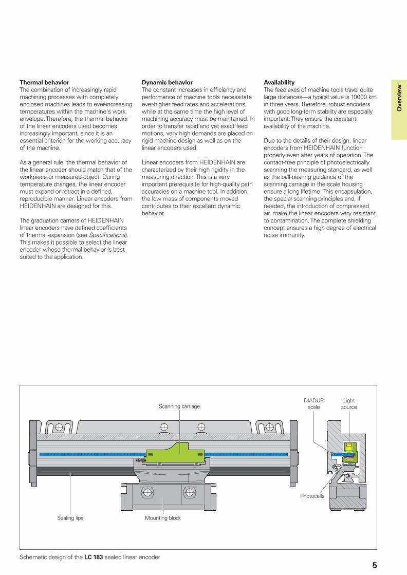
5
Scanning carriage
Mounting blockSealing lips
Photocells
DIADUR scale
Light source
Schematic design of the LC 183 sealed linear encoder
Thermal behavior
The combination of increasingly rapid machining processes with completely enclosed machines leads to ever-increasing temperatures within the machine‘s work envelope. Therefore, the thermal behavior of the linear encoders used becomes increasingly important, since it is an essential criterion for the working accuracy of the machine.
As a general rule, the thermal behavior of the linear encoder should match that of the workpiece or measured object. During temperature changes, the linear encoder must expand or retract in a defi ned, reproducible manner. Linear encoders from HEIDENHAIN are designed for this.
The graduation carriers of HEIDENHAIN linear encoders have defi ned coeffi cients of thermal expansion (see Specifi cations). This makes it possible to select the linear encoder whose thermal behavior is best suited to the application.
Dynamic behavior
The constant increases in effi ciency and performance of machine tools necessitate ever-higher feed rates and accelerations, while at the same time the high level of machining accuracy must be maintained. In order to transfer rapid and yet exact feed motions, very high demands are placed on rigid machine design as well as on the linear encoders used.
Linear encoders from HEIDENHAIN are characterized by their high rigidity in the measuring direction. This is a very important prerequisite for high-quality path accuracies on a machine tool. In addition, the low mass of components moved contributes to their excellent dynamic behavior.
Availability
The feed axes of machine tools travel quite large distances—a typical value is 10000 km in three years. Therefore, robust encoders with good long-term stability are especially important: They ensure the constant availability of the machine.
Due to the details of their design, linear encoders from HEIDENHAIN function properly even after years of operation. The contact-free principle of photoelectrically scanning the measuring standard, as well as the ball-bearing guidance of the scanning carriage in the scale housing ensure a long lifetime. This encapsulation, the special scanning principles and, if needed, the introduction of compressed air, make the linear encoders very resistant to contamination. The complete shielding concept ensures a high degree of electrical noise immunity.
Overv
iew
6
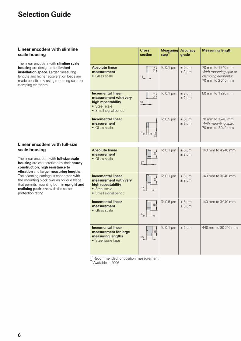
Cross
section
Measuring
step1)
Accuracy
grade
Measuring length
Absolute linear
measurement
Glass scale•
To 0.1 µm ± 5 µm± 3 µm
70 mm to 1240 mmWith mounting spar or clamping elements:70 mm to 2040 mm
Incremental linear
measurement with very
high repeatability
Steel scaleSmall signal period
••
To 0.1 µm ± 3 µm± 2 µm
50 mm to 1220 mm
Incremental linear
measurement
Glass scale•
To 0.5 µm ± 5 µm± 3 µm
70 mm to 1240 mmWith mounting spar:70 mm to 2040 mm
Absolute linear
measurement
Glass scale•
To 0.1 µm ± 5 µm± 3 µm
140 mm to 4240 mm
Incremental linear
measurement with very
high repeatability
Steel scaleSmall signal period
••
To 0.1 µm ± 3 µm± 2 µm
140 mm to 3040 mm
Incremental linear
measurement
Glass scale•
To 0.5 µm ± 5 µm± 3 µm
140 mm to 3040 mm
Incremental linear
measurement for large
measuring lengths
Steel scale tape•
To 0.1 µm ± 5 µm 440 mm to 30040 mm
1) Recommended for position measurement2) Available in 2006
Selection Guide
Linear encoders with slimline
scale housing
The linear encoders with slimline scale
housing are designed for limited
installation space. Larger measuring lengths and higher acceleration loads are made possible by using mounting spars or clamping elements.
Linear encoders with full-size
scale housing
The linear encoders with full-size scale
housing are characterized by their sturdy
construction, high resistance to
vibration and large measuring lengths. The scanning carriage is connected with the mounting block over an oblique blade that permits mounting both in upright and
reclining positions with the same protection rating.
7
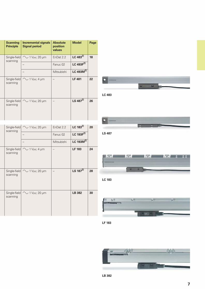
Scanning
Principle
Incremental signals
Signal period
Absolute
position
values
Model Page
Single-fi eld scanning
» 1 VPP; 20 µm EnDat 2.2 LC 4832)
18
– Fanuc 02 LC 493F2)
– Mitsubishi LC 493M2)
Single-fi eld scanning
» 1 VPP; 4 µm – LF 481 22
Single-fi eld scanning
» 1 VPP; 20 µm – LS 4872)
26
Single-fi eld scanning
» 1 VPP; 20 µm EnDat 2.2 LC 1832)
20
– Fanuc 02 LC 193F2)
– Mitsubishi LC 193M2)
Single-fi eld scanning
» 1 VPP; 4 µm – LF 183 24
Single-fi eld scanning
» 1 VPP; 20 µm – LS 1872)
28
Single-fi eld scanning
» 1 VPP; 20 µm LB 382 30
LS 487
LC 483
LF 183
LC 183
LB 382
8
Measuring Principles
Measuring Standard
HEIDENHAIN encoders with optical scanning incorporate measuring standards of periodic structures known as graduations. These graduations are applied to a carrier substrate of glass or steel. The scale substrate for large measuring lengths is a steel tape.
These precision graduations are manufactured in various photolithographic processes. Graduations can be fabricated from:
extremely hard chromium lines on glass,matte-etched lines on gold-plated steel tape, orthree-dimensional grid structures on glass or steel substrates.
The photolithographic manufacturing processes developed by HEIDENHAIN produce grating periods of typically 40 µm to 4 µm.
Along with these very fi ne grating periods, these processes permit a high defi nition and homogeneity of the line edges. Together with the photoelectric scanning method, this high edge defi nition is a precondition for the high quality of the output signals.
The master graduations are manufactured by HEIDENHAIN on custom-built high-precision ruling machines.
••
•
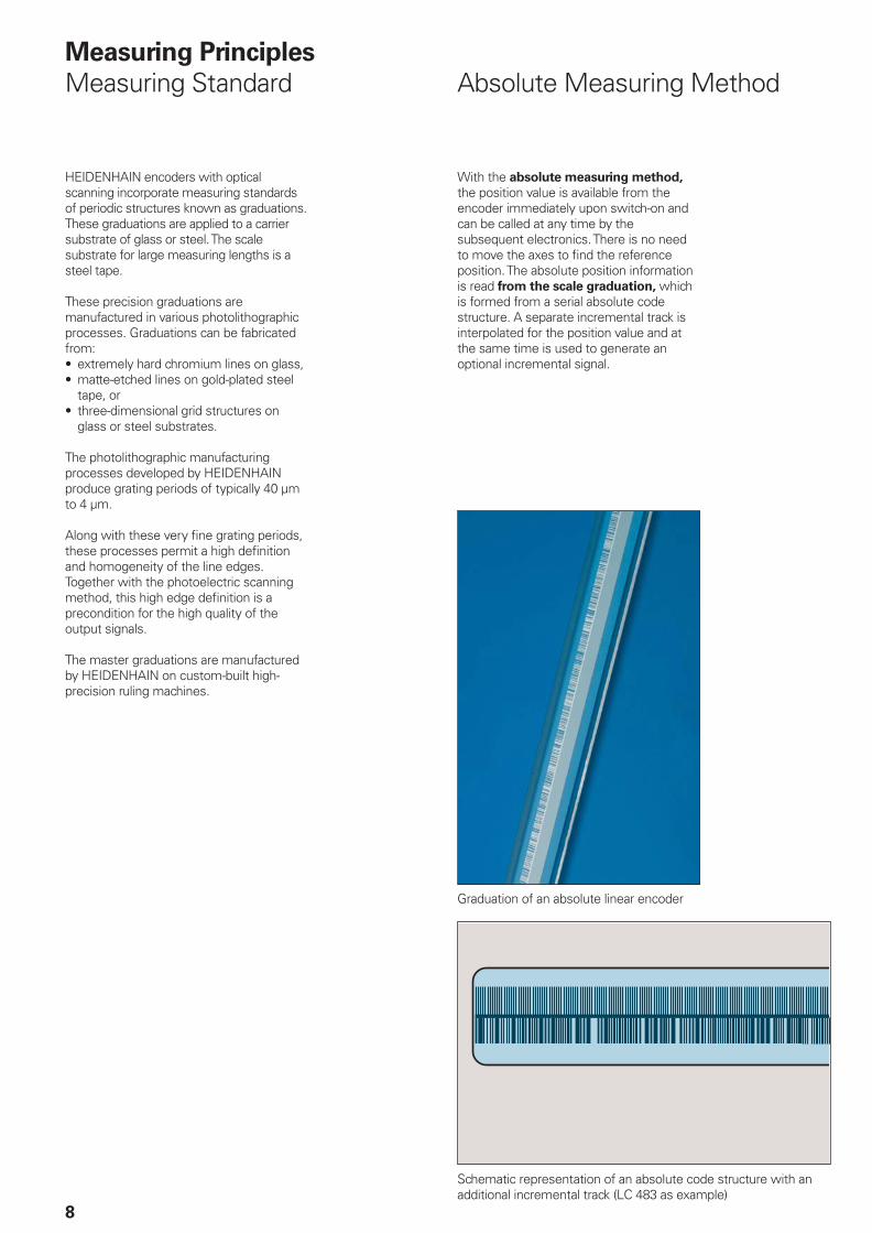
Absolute Measuring Method
With the absolute measuring method, the position value is available from the encoder immediately upon switch-on and can be called at any time by the subsequent electronics. There is no need to move the axes to fi nd the reference position. The absolute position information is read from the scale graduation, which is formed from a serial absolute code structure. A separate incremental track is interpolated for the position value and at the same time is used to generate an optional incremental signal.
Schematic representation of an absolute code structure with an additional incremental track (LC 483 as example)
Graduation of an absolute linear encoder
9
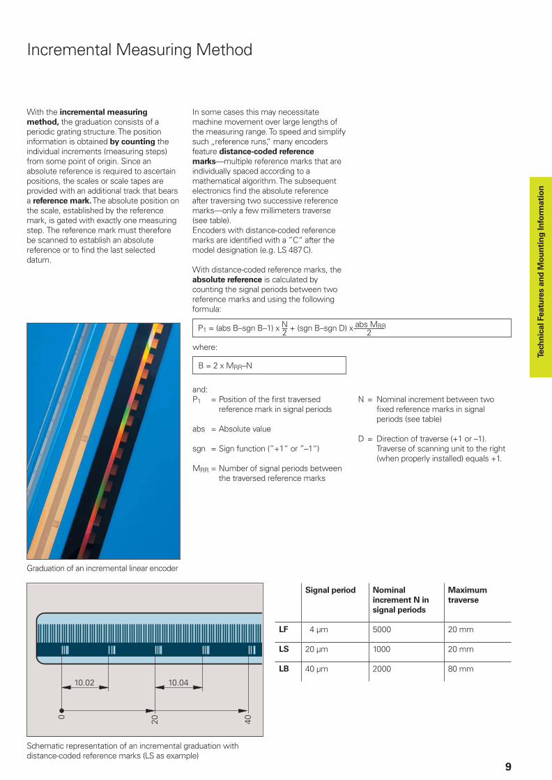
Incremental Measuring Method
With the incremental measuring
method, the graduation consists of a periodic grating structure. The position information is obtained by counting the individual increments (measuring steps) from some point of origin. Since an absolute reference is required to ascertain positions, the scales or scale tapes are provided with an additional track that bears a reference mark. The absolute position on the scale, established by the reference mark, is gated with exactly one measuring step. The reference mark must therefore be scanned to establish an absolute reference or to fi nd the last selected datum.
In some cases this may necessitate machine movement over large lengths of the measuring range. To speed and simplify such „reference runs,“ many encoders feature distance-coded reference
marks—multiple reference marks that are individually spaced according to a mathematical algorithm. The subsequent electronics fi nd the absolute reference after traversing two successive reference marks—only a few millimeters traverse (see table). Encoders with distance-coded reference marks are identifi ed with a ”C“ after the model designation (e.g. LS 487C).
With distance-coded reference marks, the absolute reference is calculated by counting the signal periods between two reference marks and using the following formula:
where:
P1 = (abs B–sgn B–1) x N + (sgn B–sgn D) x abs MRR2 2
B = 2 x MRR–N
and:P1 = Position of the fi rst traversed reference mark in signal periods
abs = Absolute value
sgn = Sign function (”+1“ or ”–1“)
MRR = Number of signal periods between the traversed reference marks
N = Nominal increment between two fi xed reference marks in signal periods (see table)
D = Direction of traverse (+1 or –1). Traverse of scanning unit to the right (when properly installed) equals +1.
Graduation of an incremental linear encoder
Schematic representation of an incremental graduation with distance-coded reference marks (LS as example)
Signal period Nominal
increment N in
signal periods
Maximum
traverse
LF 4 µm 5000 20 mm
LS 20 µm 1000 20 mm
LB 40 µm 2000 80 mm
Tech
nic
al Featu
res a
nd
Mo
un
tin
g In
form
ati
on
10
Photoelectric Scanning
Most HEIDENHAIN encoders operate using the principle of photoelectric scanning. The photoelectric scanning of a measuring standard is contact-free, and therefore without wear. This method detects even very fi ne lines, no more than a few microns wide, and generates output signals with very small signal periods.
The fi ner the grating period of a measuring standard is, the greater the effect of diffraction on photoelectric scanning. HEIDENHAIN uses two scanning principles with linear encoders:
The imaging scanning principle for grating periods from 20 µm and 40 µm.The interferential scanning principle for very fi ne graduations with grating periods of 8 µm and smaller.
•
•
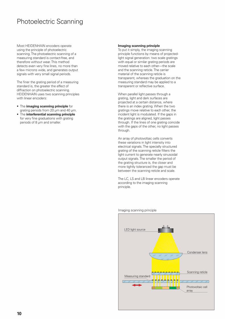
Imaging scanning principle
To put it simply, the imaging scanning principle functions by means of projected-light signal generation: two scale gratings with equal or similar grating periods are moved relative to each other—the scale and the scanning reticle. The carrier material of the scanning reticle is transparent, whereas the graduation on the measuring standard may be applied to a transparent or refl ective surface.
When parallel light passes through a grating, light and dark surfaces are projected at a certain distance, where there is an index grating. When the two gratings move relative to each other, the incident light is modulated. If the gaps in the gratings are aligned, light passes through. If the lines of one grating coincide with the gaps of the other, no light passes through.
An array of photovoltaic cells converts these variations in light intensity into electrical signals. The specially structured grating of the scanning reticle fi lters the light current to generate nearly sinusoidal output signals. The smaller the period of the grating structure is, the closer and more tightly toleranced the gap must be between the scanning reticle and scale.
The LC, LS and LB linear encoders operate according to the imaging scanning principle.
Imaging scanning principle
LED light source
Measuring standard
Condenser lens
Scanning reticle
Photovoltaic cell array
11
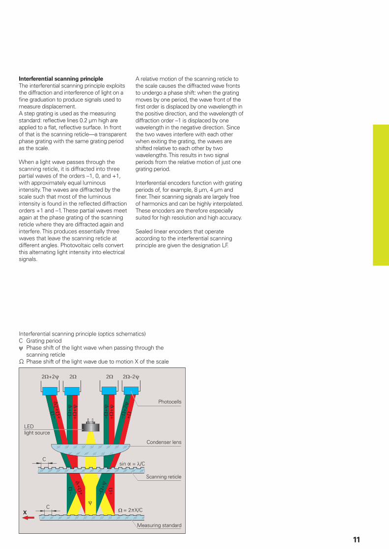
Interferential scanning principle
The interferential scanning principle exploits the diffraction and interference of light on a fi ne graduation to produce signals used to measure displacement. A step grating is used as the measuring standard: refl ective lines 0.2 µm high are applied to a fl at, refl ective surface. In front of that is the scanning reticle—a transparent phase grating with the same grating period as the scale.
When a light wave passes through the scanning reticle, it is diffracted into three partial waves of the orders –1, 0, and +1, with approximately equal luminous intensity. The waves are diffracted by the scale such that most of the luminous intensity is found in the refl ected diffraction orders +1 and –1. These partial waves meet again at the phase grating of the scanning reticle where they are diffracted again and interfere. This produces essentially three waves that leave the scanning reticle at different angles. Photovoltaic cells convert this alternating light intensity into electrical signals.
A relative motion of the scanning reticle to the scale causes the diffracted wave fronts to undergo a phase shift: when the grating moves by one period, the wave front of the fi rst order is displaced by one wavelength in the positive direction, and the wavelength of diffraction order –1 is displaced by one wavelength in the negative direction. Since the two waves interfere with each other when exiting the grating, the waves are shifted relative to each other by two wavelengths. This results in two signal periods from the relative motion of just one grating period.
Interferential encoders function with grating periods of, for example, 8 µm, 4 µm and fi ner. Their scanning signals are largely free of harmonics and can be highly interpolated. These encoders are therefore especially suited for high resolution and high accuracy.
Sealed linear encoders that operate according to the interferential scanning principle are given the designation LF.
LEDlight source
Measuring standard
Condenser lens
Scanning reticle
Photocells
Interferential scanning principle (optics schematics)C Grating periodψ Phase shift of the light wave when passing through the
scanning reticle− Phase shift of the light wave due to motion X of the scale
12
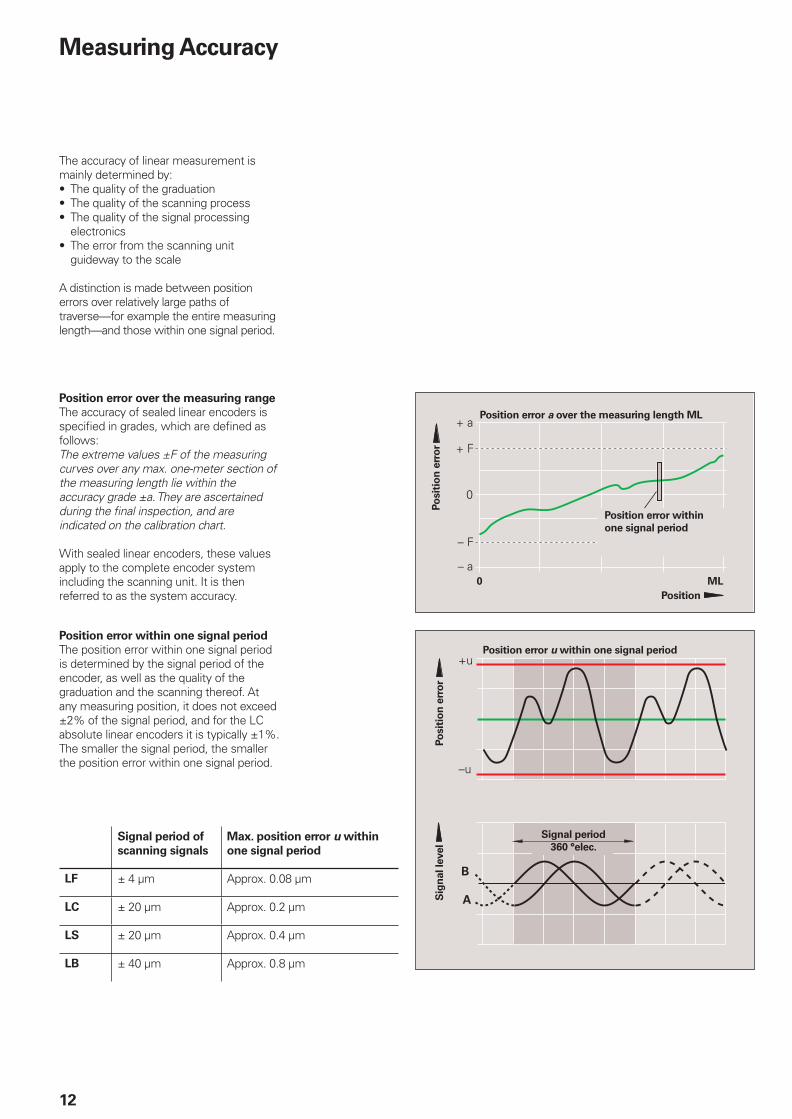
The accuracy of linear measurement is mainly determined by:
The quality of the graduationThe quality of the scanning processThe quality of the signal processing electronicsThe error from the scanning unit guideway to the scale
A distinction is made between position errors over relatively large paths of traverse—for example the entire measuring length—and those within one signal period.
•••
•
���
Position error a over the measuring length ML
Po
sit
ion
err
or
Position
Position error within
one signal period
Po
sit
ion
err
or
Position error u within one signal period
Sig
nal le
vel
Signal period
360 °elec.
Measuring Accuracy
Position error over the measuring range
The accuracy of sealed linear encoders is specifi ed in grades, which are defi ned as follows:The extreme values ±F of the measuring curves over any max. one-meter section of the measuring length lie within the accuracy grade ±a. They are ascertained during the fi nal inspection, and are indicated on the calibration chart.
With sealed linear encoders, these values apply to the complete encoder system including the scanning unit. It is then referred to as the system accuracy.
Position error within one signal period
The position error within one signal period is determined by the signal period of the encoder, as well as the quality of the graduation and the scanning thereof. At any measuring position, it does not exceed ±2% of the signal period, and for the LC absolute linear encoders it is typically ±1%.The smaller the signal period, the smaller the position error within one signal period.
Signal period of
scanning signals
Max. position error u within
one signal period
LF ± 4 µm Approx. 0.08 µm
LC ± 20 µm Approx. 0.2 µm
LS ± 20 µm Approx. 0.4 µm
LB ± 40 µm Approx. 0.8 µm
13
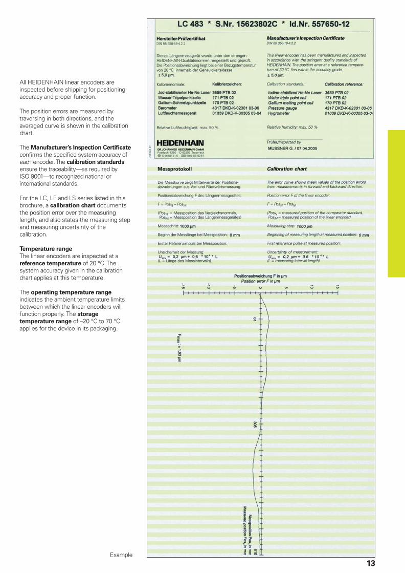
All HEIDENHAIN linear encoders are inspected before shipping for positioning accuracy and proper function.
The position errors are measured by traversing in both directions, and the averaged curve is shown in the calibration chart.
The Manufacturer’s Inspection Certifi cate
confi rms the specifi ed system accuracy of each encoder. The calibration standards ensure the traceability—as required by ISO 9001—to recognized national or international standards.
For the LC, LF and LS series listed in this brochure, a calibration chart documents the position error over the measuring length, and also states the measuring step and measuring uncertainty of the calibration.
Temperature range
The linear encoders are inspected at a reference temperature of 20 °C. The system accuracy given in the calibration chart applies at this temperature.
The operating temperature range indicates the ambient temperature limits between which the linear encoders will function properly. The storage
temperature range of –20 °C to 70 °C applies for the device in its packaging.
Example
14
Mechanical Design Types and Mounting Guidelines
Linear Encoders with Small Cross Section
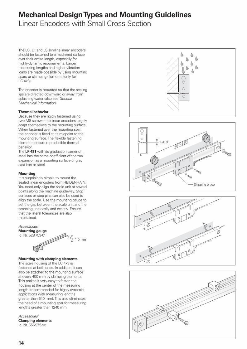
The LC, LF and LS slimline linear encoders should be fastened to a machined surface over their entire length, especially for highly-dynamic requirements. Larger measuring lengths and higher vibration loads are made possible by using mounting spars or clamping elements (only for LC 4x3).
The encoder is mounted so that the sealing lips are directed downward or away from splashing water (also see General Mechanical Information).
Thermal behavior
Because they are rigidly fastened using two M8 screws, the linear encoders largely adapt themselves to the mounting surface. When fastened over the mounting spar, the encoder is fi xed at its midpoint to the mounting surface. The fl exible fastening elements ensure reproducible thermal behavior.The LF 481 with its graduation carrier of steel has the same coeffi cient of thermal expansion as a mounting surface of gray cast iron or steel.
Mounting
It is surprisingly simple to mount the sealed linear encoders from HEIDENHAIN: You need only align the scale unit at several points along the machine guideway. Stop surfaces or stop pins can also be used to align the scale. Use the mounting gauge to set the gap between the scale unit and the scanning unit easily and exactly. Ensure that the lateral tolerances are also maintained.
Accessories:Mounting gauge
Id. Nr. 528753-01
Mounting with clamping elements
The scale housing of the LC 4x3 is fastened at both ends. In addition, it can also be attached to the mounting surface at every 400 mm by clamping elements. This makes it very easy to fasten the housing at the center of the measuring length (recommended for highly-dynamic applications with measuring lengths greater than 640 mm). This also eliminates the need of a mounting spar for measuring lengths greater than 1240 mm.
Accessories:Clamping elements
Id. Nr. 556975-xx
����������
����
Shipping brace
����
15
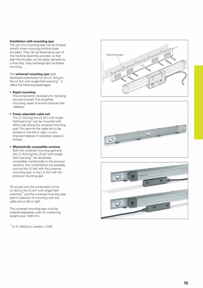
Installation with mounting spar
The use of a mounting spar can be of great benefi t when mounting slimline linear encoders. They can be fastened as part of the machine assembly process, so that later the encoder can be easily clamped as a fi nal step. Easy exchange also facilitates servicing.
The universal mounting spar was developed specifi cally for the LC 4x3 and the LS 4x7 with single-fi eld scanning1). It offers the following advantages:
Rapid mounting
The components necessary for clamping are premounted. This simplifi es mounting, saves time and improves the reliability.
Freely selectable cable exit
The LC 4x3 and the LS 4x7 with single-fi eld scanning1) can be mounted with either side facing the universal mounting spar. This permits the cable exit to be located on the left or right—a very important feature if installation space is limited.
Mechanically compatible versions
Both the universal mounting spar and the LC 4x3 and the LS 4x7 with single-fi eld scanning1) are absolutely compatible mechanically to the previous versions. Any combinations are possible, such as the LS 4x6 with the universal mounting spar, or the LC 4x3 with the previous mounting spar.
Of course only the combination of the LC 4x3 or the LS 4x7 with single-fi eld scanning1) und the universal mounting spar permit selection of mounting with the cable exit at left or right.
The universal mounting spar must be ordered separately, even for measuring lengths over 1240 mm.
1) Id. Nr. 56052x-xx; available in 2006
•
•
•
Mounting spar
16
Linear Encoders with Large Cross Section
���������
Shipping brace
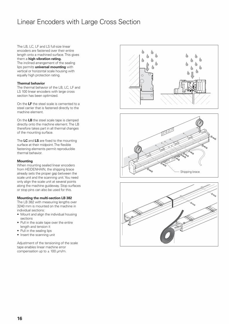
The LB, LC, LF and LS full-size linear encoders are fastened over their entire length onto a machined surface. This gives them a high vibration rating.
The inclined arrangement of the sealing lips permits universal mounting with vertical or horizontal scale housing with equally high protection rating.
Thermal behavior
The thermal behavior of the LB, LC, LF and LS 100 linear encoders with large cross section has been optimized.
On the LF the steel scale is cemented to a steel carrier that is fastened directly to the machine element.
On the LB the steel scale tape is clamped directly onto the machine element. The LB therefore takes part in all thermal changes of the mounting surface.
The LC and LS are fi xed to the mounting surface at their midpoint. The fl exible fastening elements permit reproducible thermal behavior.
Mounting
When mounting sealed linear encoders from HEIDENHAIN, the shipping brace already sets the proper gap between the scale unit and the scanning unit. You need only align the scale unit at several points along the machine guideway. Stop surfaces or stop pins can also be used for this.
Mounting the multi-section LB 382
The LB 382 with measuring lengths over 3240 mm is mounted on the machine in individual sections:
Mount and align the individual housing sectionsPull in the scale tape over the entire length and tension itPull in the sealing lipsInsert the scanning unit
Adjustment of the tensioning of the scale tape enables linear machine error compensation up to ± 100 µm/m.
•
•
••
17
General Mechanical Information
Mounting
To simplify cable routing, the mounting block of the scanning unit is usually screwed onto a stationary machine part.The mounting location for the linear encoders should be carefully considered in order to ensure both optimum accuracy and the longest possible service life.
The encoder should be mounted as closely as possible to the working plane to keep the Abbe error low.To function properly, linear encoders must not be continuously subjected to strong vibration; the more solid parts of the machine tool provide the best mounting surface in this respect. Encoders should not be mounted on hollow parts or with adapters. A mounting spar is recommended for the sealed linear encoders with small cross section.The linear encoders should be mounted away from sources of heat to avoid temperature infl uences.
Acceleration
Linear encoders are subject to various types of acceleration during operation and mounting.
The indicated maximum values for vibration apply for frequencies of 55 to 2000 Hz (IEC 60068-2-6). Any acceleration exceeding permissible values, for example due to resonance depending on the application and mounting, might damage the encoder. Comprehensive tests of the entire
system are required.
The maximum permissible acceleration values (semi-sinusoidal shock) for shock
and impact are valid for 11 ms (IEC 60068-2-27).Under no circum-stances should a hammer or similar implement be used to adjust or position the encoder.
Required moving force
The required moving force is the maximum force required to move the scale unit relative to the scanning unit.
Expendable parts
In particular the following parts in encoders from HEIDENHAIN are subject to wear:
LED light sourceBearingsSealing lips
•
•
•
•
•
•••
Protection
Sealed linear encoders fulfi ll the require-ments for IP 53 protection according to IEC 60529, provided that they are mounted with the sealing lips facing away from splash water. If necessary, provide a separate protective cover. If the encoder is exposed to particularly heavy concentrations of coolant and mist, compressed air can be conducted into the scale housing to provide
IP 64 protection to more effectively prevent the ingress of contamination. The LB, LC, LF and LS sealed linear encoders from HEIDENHAIN are therefore equipped with inlets at both end pieces and on the mounting block of the scanning unit.
The compressed air introduced directly onto the encoders must be cleaned by a micro-fi lter and must comply with the following quality classes as per ISO 8573-1:
Solid contaminant: Class 1(max. particle size 0.1 µm and max. particle density 0.1 mg/m3 at 1 · 105 Pa)Total oil content: Class 1(max. oil concentration 0.01 mg/m3 at 1 · 105 Pa)Maximum pressure dew point: Class 4(+3 °C at 2 · 105 Pa)
•
•
•
The required air fl ow is 7 to 10 l/min per linear encoder; permissible pressure is in the range of 0.6 to 1 bar (9 to 14 psi). The compressed air fl ows through connecting pieces with integrated throttle (included with LB, LC, LF, LS 1x6, and LS 4x6 linear encoders).
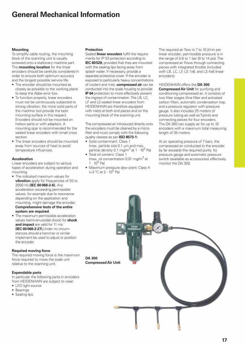
HEIDENHAIN offers the DA 300
Compressed Air Unit for purifying and conditioning compressed air. It consists of two fi lter stages (fi ne fi lter and activated carbon fi lter), automatic condensation trap, and a pressure regulator with pressure gauge. It also includes 25 meters of pressure tubing as well as T-joints and connecting pieces for four encoders. The DA 300 can supply air for up to 10 encoders with a maximum total measuring length of 35 meters.
At an operating pressure of 7 bars, the compressed air conducted to the encoder by far exceeds the required purity. Its pressure gauge and automatic pressure switch (available as accessories) effectively monitor the DA 300.
DA 300
Compressed Air Unit
18
����
�����
������
�����
�
� ����
���
�
������ ���������
����
��
����
����
����
�������
��
���
���� �
����
�������
�����
��
�
��
����
���
�
��
�
��
��
��
���
������������� �������������
���������� ����� ���������� �����
��������� �� �����
������� �
��
�������
��������
�������� ������
�
�����
���
���
����
���
��
��� ��� �� ��
��� ���
��
�
��
���
�
��
������
�
�
���
� ��������������������
�
�
�
�����
���
������
���
�
����
���
��
��������
�
�
����
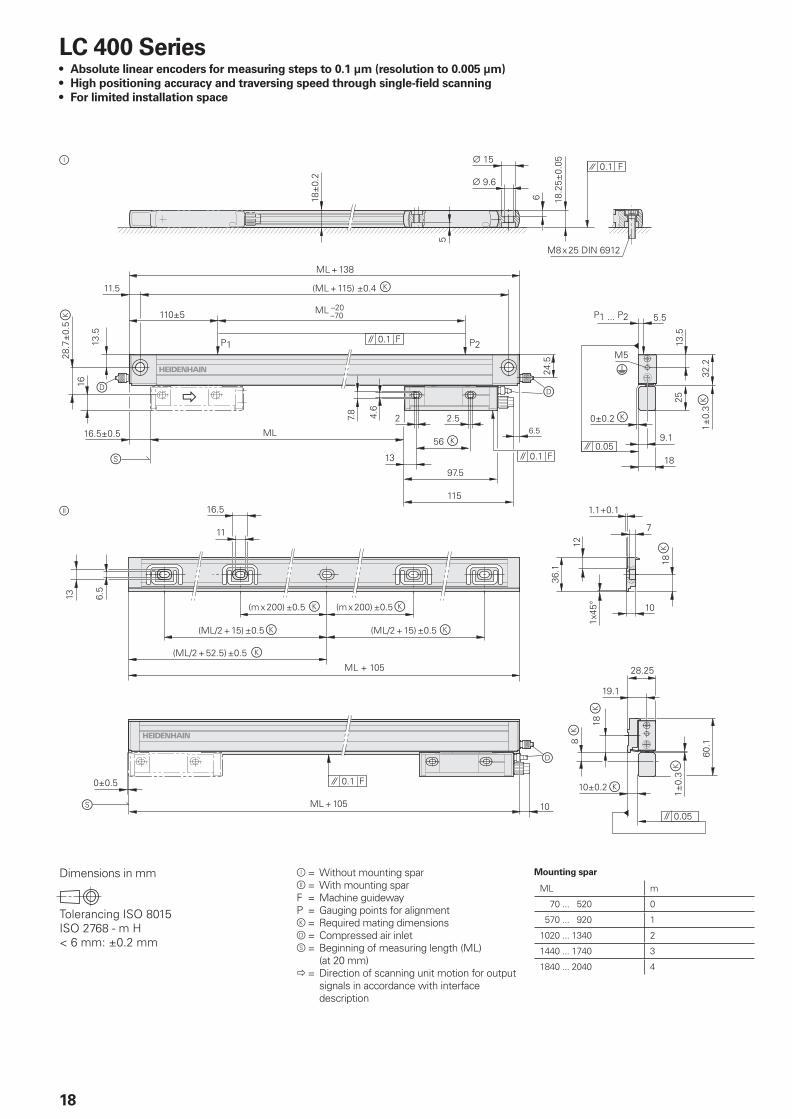
LC 400 SeriesAbsolute linear encoders for measuring steps to 0.1 µm (resolution to 0.005 µm)
High positioning accuracy and traversing speed through single-fi eld scanning
For limited installation space
•
•
•
Dimensions in mm
���� !"#$"%��&'���� �&'������(��)*���+������
�
Ô
Õ
Ô = Without mounting sparÕ = With mounting sparF = Machine guidewayP = Gauging points for alignmentk = Required mating dimensionsd = Compressed air inlets = Beginning of measuring length (ML) (at 20 mm)� = Direction of scanning unit motion for output signals in accordance with interface description
Mounting spar
ML m
70 ... 520 0
570 ... 920 1
1020 ... 1340 2
1440 ... 1740 3
1840 ... 2040 4
19
LC 483 with mounting spar
Specifi cations LC 4831)
LC 493F1)
LC 493M1)
Measuring standard
Expansion coeffi cientDIADUR glass scale with absolute track and incremental trackÞtherm approx. 8 x 10⁻⁶ K–1, with mounting spar: Þtherm approx. 9 x 10⁻⁶ K–1
Accuracy grade* ± 3 µm, ± 5 µm
Measuring length ML* in mm Mounting spar* or clamping elements* optional 70 120 170 220 270 320 370 420 470 520 570 620 720 770820 920 1020 1140 1240
Only with mounting spar* or clamping elements*
1340 1440 1540 1640 1740 1840 2040
Absolute position values EnDat 2.2 Serial interface Fanuc 02 Mitsubishi high-speed serial interface
Resolution Accuracy ± 3 µm Accuracy ± 5 µm
0.005 µm0.01 µm
0.01 µm0.05 µm
Calculation time tcal EnDat 2.1 command set EnDat 2.2 command set
< 1 ms† 5 µs
––
Incremental signals » 1 VPP2) –
Grating period/signal period 20 µm –
Cutoff frequency –3dB ‡ 150 kHz –
Power supply without load 3.6 to 5.25 V/< 300 mA
Electrical connection Separate adapter cable (1 m/3 m/6 m/9 m) connectable to mounting block
Cable length3) † 150 m; depending on the
interface and subsequent electronics
†30 m †20 m
Traversing speed † 180 m/min
Required moving force † 5 N
Vibration 55 to 2000 Hz
Shock 11 msAcceleration
Without mounting spar: † 100 m/s2 (IEC 60068-2-6)With mounting spar and cable exit right/left: † 200 m/s2/100 m/s2 (IEC 60068-2-6)† 300 m/s2 (IEC 60068-2-27)† 100 m/s2 in measuring direction
Operating temperature 0 to 50 °C
Protection IEC 60529 IP 53 when installed according to mounting instructionsIP 64 with use of compressed air from DA 300
Weight Encoder: 0.2 kg + 0.5 kg/m measuring length, mounting spar: 0.9 kg/m
* Please select when ordering1) Available in 2006. Specifi cations preliminary. 2) Depends on adapter cable 3) With HEIDENHAIN cable
LC 483 without mounting spar
Sp
ecifi c
ati
on
s
20
�����������
������ ��
��
��
� �����
�
�
�
�
�
,�,� �,�
�"�������������
���������� ������
��
������� ��
�����������������
�
���� ������ ��
������ �� ��
�
���
�� �
��������
����
���
,
! ! ! !
������
����
�&'������(������ �(����
����
�
������
������
�� ����
�
���
���
�����
�&'������(���(��
������ �
��
����
� �
���
��
�
���
���
��
��&'������(���������(������&'������(�� ������(�����
��&'�����(���(����)-��&'������(� �(����)-�
�� �
���
�
�
��������
�
�
�
����
���
���
�
� �
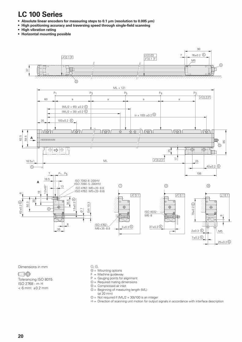
LC 100 SeriesAbsolute linear encoders for measuring steps to 0.1 µm (resolution to 0.005 µm)
High positioning accuracy and traversing speed through single-fi eld scanning
High vibration rating
Horizontal mounting possible
•
•
•
•
Dimensions in mm
���� !"#$"%��&'���� �&'������(��)*���+������
Ô, Õ,Ö = Mounting optionsF = Machine guidewayP = Gauging points for alignmentk = Required mating dimensionsd = Compressed air inlets = Beginning of measuring length (ML) (at 20 mm)z = Not required if (ML/2 + 30)/100 is an integer� = Direction of scanning unit motion for output signals in accordance with interface description
�
21
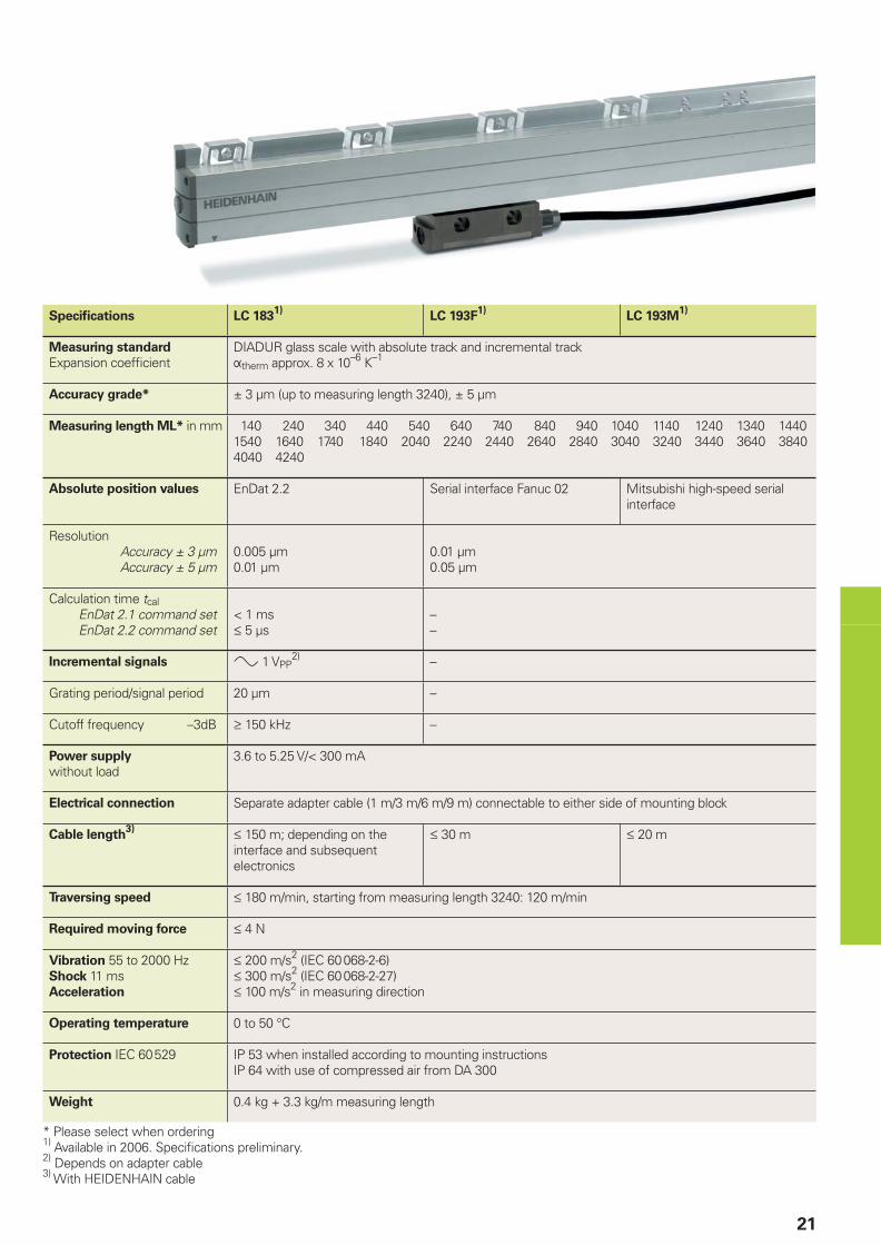
Specifi cations LC 1831)
LC 193F1)
LC 193M1)
Measuring standard
Expansion coeffi cientDIADUR glass scale with absolute track and incremental trackÞtherm approx. 8 x 10⁻⁶ K–1
Accuracy grade* ± 3 µm (up to measuring length 3240), ± 5 µm
Measuring length ML* in mm 140 240 340 440 540 640 740 840 940 1040 1140 1240 1340 14401540 1640 1740 1840 2040 2240 2440 2640 2840 3040 3240 3440 3640 38404040 4240
Absolute position values EnDat 2.2 Serial interface Fanuc 02 Mitsubishi high-speed serial interface
Resolution Accuracy ± 3 µm Accuracy ± 5 µm
0.005 µm0.01 µm
0.01 µm0.05 µm
Calculation time tcal EnDat 2.1 command set EnDat 2.2 command set
< 1 ms† 5 µs
––
Incremental signals » 1 VPP2) –
Grating period/signal period 20 µm –
Cutoff frequency –3dB ‡ 150 kHz –
Power supply
without load3.6 to 5.25 V/< 300 mA
Electrical connection Separate adapter cable (1 m/3 m/6 m/9 m) connectable to either side of mounting block
Cable length3) † 150 m; depending on the
interface and subsequent electronics
† 30 m † 20 m
Traversing speed † 180 m/min, starting from measuring length 3240: 120 m/min
Required moving force † 4 N
Vibration 55 to 2000 HzShock 11 msAcceleration
† 200 m/s2 (IEC 60068-2-6)† 300 m/s2 (IEC 60068-2-27)† 100 m/s2 in measuring direction
Operating temperature 0 to 50 °C
Protection IEC 60529 IP 53 when installed according to mounting instructionsIP 64 with use of compressed air from DA 300
Weight 0.4 kg + 3.3 kg/m measuring length
* Please select when ordering1) Available in 2006. Specifi cations preliminary.2) Depends on adapter cable3) With HEIDENHAIN cable
22
LF 481Incremental linear encoder for measuring steps to 0.1 µm
High positioning accuracy through single-fi eld scanning
Thermal behavior similar to steel or cast iron
For limited installation space
•
•
•
•
�� ���
��
����
��
�
��
�������
�������������
������������� � ������������� �
� ������������� �
���������� �
�������
���
��
�
�
��
����
����
�
����
� ���
���
���� �
�
�����
������
��
����
��
����
��
����
�
� �� ��
�
���
��
�
�
���
��
���
� ��
�����
��
�
��
��
�
�
���������
������������
��������
���� �
���� �
��
���
���
���
���
�
���
���
�
����� �
�
����
�
�����
����
�
��
����������
��������
�
�
��
��
�
��
�����
���
��
����
��������
��
�����
��
�
�
�
�������������
������ �!����
�
�������
��
�
���
�������
Dimensions in mm
���� !"#$"%��&'���� �&'������(��)*���+������
�
Ô
Õ
Ô = Without mounting sparÕ = With mounting sparF = Machine guidewayP = Gauging points for alignmentk = Required mating dimensionsd = Compressed air inletr = Reference mark position on LF 481 2 reference marks for measuring lengths
50 ... 1000 1120 ... 1220
z = 25zi = ML – 50
z = 35zi = ML – 70
c = Reference mark position on LF 481Cs = Beginning of measuring length (ML)� = Direction of scanning unit motion for output signals in accordance with interface description
Mounting spar
ML m
50 ... 500 0
550 ... 900 1
1000 ... 1220 2
23
Specifi cations LF 481
Measuring standard
Expansion coeffi cientDIADUR phase grating on steelÞtherm approx. 10 x 10–6 K–1, with mounting spar: Þtherm ca. 9 x 10⁻⁶ K–1
Accuracy grade* ± 3 µm, ± 5 µm
Measuring length ML* in mm Mounting spar* recommended 50 100 150 200 250 300 350 400 450 500 550 600 650 700750 800 900 1000 1120 1220
Incremental signals »1 VPP
Grating periodSignal period
8 µm4 µm
Reference marks* LF 481
LF 481C
ML 50 mm: 1 reference mark at midpointML 100 to 1000 mm: 2, located 25 mm from the beginning and end of the measuring lengthFrom ML 1120 mm: 2, located 35 mm from the beginning and end of the measuring lengthDistance-coded
Cutoff frequency –3dB ‡ 200 kHz
Power supply
without load5 V ± 5 %/< 200 mA
Electrical connection Separate adapter cable (1 m/3 m/6 m/9 m) connectable to mounting block
Cable length1) † 150 m
Traversing speed † 30 m/min
Required moving force † 5 N
Vibration 55 to 2000 HzShock 11 msAcceleration
† 80 m/s2 (IEC 60068-2-6)† 100 m/s2 (IEC 60068-2-27)† 30 m/s2 in measuring direction
Operating temperature 0 to 50 °C
Protection IEC 60529 IP 53 when installed according to mounting instructionsIP 64 with use of compressed air from DA 300
Weight without mounting spar 0.4 kg + 0.5 kg/m measuring length
* Please select when ordering1) With HEIDENHAIN cable
LF 481 without mounting spar
LF 481 with mounting spar
24
��
�
�
"
����
��
����
��
����
�
����
��
� �� �� ��
�
��
���� �
��� �
���
���� �
��������
�
�
��
�������
�
���
��� ���
�#����������� �
��
������ ��� $
$
����
����� �� ��
���
��
���
��
�
����� ��
��
����
�
�
������
���
��
��
�
������
���
����
���% &���� ��
���
����
��
���
�
������
����
���� �
�
���
���
������
���
����
� ����
����
�����
�����
��
$'$
�
�
�������
���
���
����
�
����
���
(��
����
���
��
�
���
"
�
LF 183Incremental linear encoder for measuring steps to 0.1 µm
High positioning accuracy through single-fi eld scanning
Thermal behavior similar to steel or cast iron
High vibration rating
Horizontal mounting possible
•
•
•
•
•
Dimensions in mm
���� !"#$"%��&'���� �&'������(��)*���+������
�
Ô, Õ,Ö = Mounting optionsF = Machine guidewayP = Gauging points for alignmentk = Required mating dimensionsd = Compressed air inletr = Reference mark position on LF 183c = Reference mark position on LF 183Cs = Beginning of measuring length (ML)� = Direction of scanning unit motion for output signals in accordance with interface description
25
Specifi cations LF 183
Measuring standard
Expansion coeffi cientDIADUR phase grating on steelÞtherm approx. 10 x 10–6 K–1
Accuracy grade* ± 3 µm, ± 2 µm
Measuring length ML* in mm 140 240 340 440 540 640 740 840 940 1040 1140 1240 1340 14401540 1640 1740 1840 2040 2240 2440 2640 2840 3040
Incremental signals »1 VPP
Grating periodSignal period
8 µm4 µm
Reference marks* LF 183
LF 183C
Selectable with magnets every 50 mmStandard setting: 1 reference mark in the centerDistance-coded
Cutoff frequency –3dB ‡ 200 kHz
Power supply
without load5 V ± 5 %/< 200 mA
Electrical connection Separate adapter cable (1 m/3 m/6 m/9 m) connectable to mounting block
Cable length1) † 150 m
Traversing speed † 60 m/min
Required moving force † 4 N
Vibration 55 to 2000 HzShock 11 msAcceleration
† 150 m/s2 (IEC 60068-2-6)† 300 m/s2 (IEC 60068-2-27)† 100 m/s2 in measuring direction
Operating temperature 0 to 40 °C
Protection IEC 60529 IP 53 when installed according to mounting instructionsIP 64 with use of compressed air from DA 300
Weight 1.1 kg + 3.8 kg/m measuring length
* Please select when ordering1) With HEIDENHAIN cable
26
����
��
����
����
����
�������
��
����
�
�
����
�������
�����
��
� ��
�
��
����
���
�
��
�
��
��
��
���
������������� �������������
���������� ����� ���������� �����
��������� �� �����
�������
���
�������
��
�
�����
���
������
����
����
���
��
���
�
��
��������
� �
��������
�������� ������
�
�����
���
���
����
���
��� ���
����
��������������������
� �
�
���
�
��� ���
��
��
���
�
�����
� ��
�
. .$
��
�
����
�
����
�
����
�
�
�� �� ��
�
����
�����
������
�����
�
� ����
���
�
������ ���������
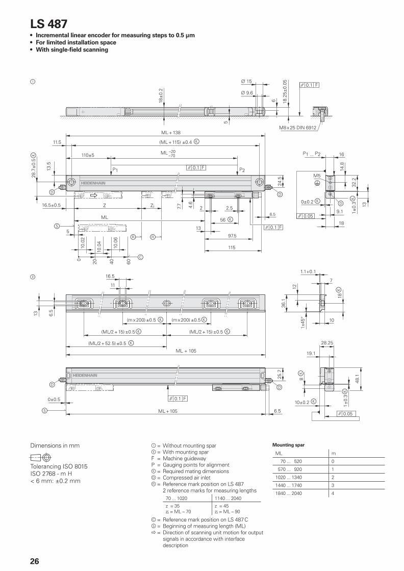
LS 487Incremental linear encoder for measuring steps to 0.5 µm
For limited installation space
With single-fi eld scanning
•
•
•
�
Ô
Õ
Dimensions in mm
���� !"#$"%��&'���� �&'������(��)*���+������
Mounting spar
ML m
70 ... 520 0
570 ... 920 1
1020 ... 1340 2
1440 ... 1740 3
1840 ... 2040 4
Ô = Without mounting sparÕ = With mounting sparF = Machine guidewayP = Gauging points for alignmentk = Required mating dimensionsd = Compressed air inletr = Reference mark position on LS 487 2 reference marks for measuring lengths
70 ... 1020 1140 ... 2040
z = 35zi = ML – 70
z = 45zi = ML – 90
c = Reference mark position on LS 487Cs = Beginning of measuring length (ML)� = Direction of scanning unit motion for output signals in accordance with interface description
27
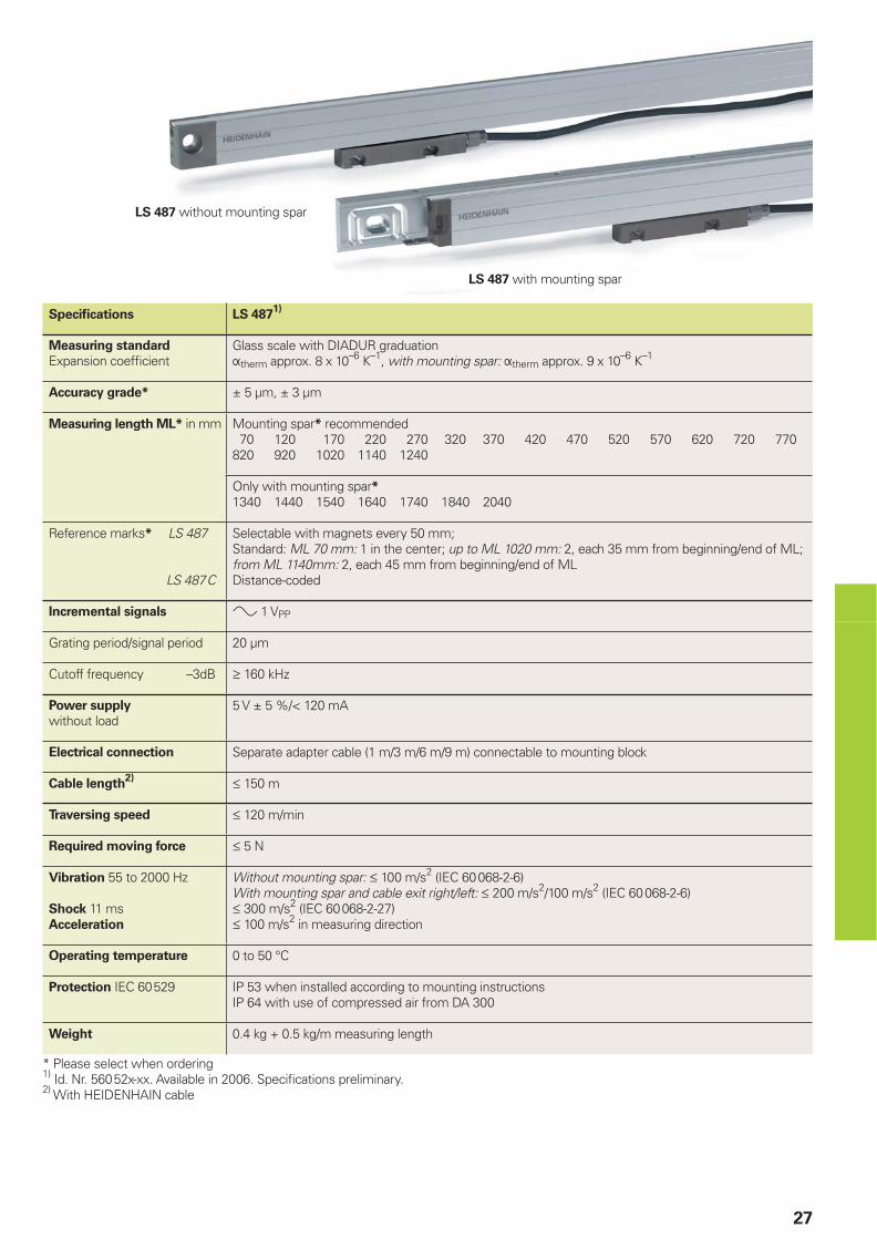
LS 487 without mounting spar
LS 487 with mounting spar
Specifi cations LS 4871)
Measuring standard
Expansion coeffi cientGlass scale with DIADUR graduationÞtherm approx. 8 x 10⁻⁶ K–1, with mounting spar: Þtherm approx. 9 x 10⁻⁶ K–1
Accuracy grade* ± 5 µm, ± 3 µm
Measuring length ML* in mm Mounting spar* recommended 70 120 170 220 270 320 370 420 470 520 570 620 720 770820 920 1020 1140 1240
Only with mounting spar*1340 1440 1540 1640 1740 1840 2040
Reference marks* LS 487
LS 487C
Selectable with magnets every 50 mm;Standard: ML 70 mm: 1 in the center; up to ML 1020 mm: 2, each 35 mm from beginning/end of ML;from ML 1140mm: 2, each 45 mm from beginning/end of MLDistance-coded
Incremental signals » 1 VPP
Grating period/signal period 20 µm
Cutoff frequency –3dB ‡ 160 kHz
Power supply
without load5 V ± 5 %/< 120 mA
Electrical connection Separate adapter cable (1 m/3 m/6 m/9 m) connectable to mounting block
Cable length2) † 150 m
Traversing speed † 120 m/min
Required moving force † 5 N
Vibration 55 to 2000 Hz
Shock 11 msAcceleration
Without mounting spar: † 100 m/s2 (IEC 60068-2-6)With mounting spar and cable exit right/left: † 200 m/s2/100 m/s2 (IEC 60068-2-6)† 300 m/s2 (IEC 60068-2-27)† 100 m/s2 in measuring direction
Operating temperature 0 to 50 °C
Protection IEC 60529 IP 53 when installed according to mounting instructionsIP 64 with use of compressed air from DA 300
Weight 0.4 kg + 0.5 kg/m measuring length
* Please select when ordering1) Id. Nr. 56052x-xx. Available in 2006. Specifi cations preliminary.2) With HEIDENHAIN cable
28
�����������
������ ��
��
��
� �����
�
�
�
��������
����
���
�
����
����
�
����
�
����
�
� �� �� ��
�
����
�
�
�
,�,� �,�
�"�������������
���������� ������
��
������� ��
�
���� ���������
������ �� ��
�
���
�� �
������
����
�&'������(������ �(����
����
�
������
������
�� ����
�
���
���
�
����
�&'������(���(��
������ �
��
����
� �
���
��
�
���
���
��
��&'������(���������(������&'������(�� ������(�����
��&'�����(���(����)-��&'������(� �(����)-�
�� �
���
�
�
��������
�
�
�
����
���
���
�
� �
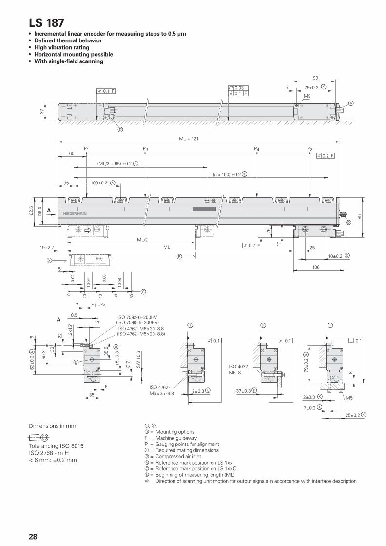
LS 187Incremental linear encoder for measuring steps to 0.5 µm
Defi ned thermal behavior
High vibration rating
Horizontal mounting possible
With single-fi eld scanning
•
•
•
•
•
Dimensions in mm
���� !"#$"%��&'���� �&'������(��)*���+������
�
Ô, Õ,Ö = Mounting optionsF = Machine guidewayP = Gauging points for alignmentk = Required mating dimensionsd = Compressed air inletr = Reference mark position on LS 1xxc = Reference mark position on LS 1xxCs = Beginning of measuring length (ML)� = Direction of scanning unit motion for output signals in accordance with interface description
29
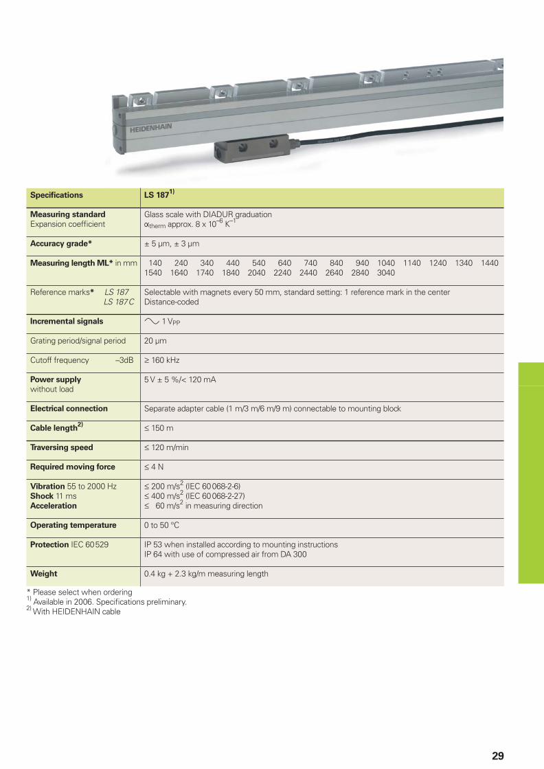
Specifi cations LS 1871)
Measuring standard
Expansion coeffi cientGlass scale with DIADUR graduationÞtherm approx. 8 x 10⁻⁶ K–1
Accuracy grade* ± 5 µm, ± 3 µm
Measuring length ML* in mm 140 240 340 440 540 640 740 840 940 1040 1140 1240 1340 14401540 1640 1740 1840 2040 2240 2440 2640 2840 3040
Reference marks* LS 187 LS 187C
Selectable with magnets every 50 mm, standard setting: 1 reference mark in the centerDistance-coded
Incremental signals » 1 VPP
Grating period/signal period 20 µm
Cutoff frequency –3dB ‡ 160 kHz
Power supply
without load5 V ± 5 %/< 120 mA
Electrical connection Separate adapter cable (1 m/3 m/6 m/9 m) connectable to mounting block
Cable length2) † 150 m
Traversing speed † 120 m/min
Required moving force † 4 N
Vibration 55 to 2000 HzShock 11 msAcceleration
† 200 m/s2 (IEC 60068-2-6)† 400 m/s2 (IEC 60068-2-27)† 60 m/s2 in measuring direction
Operating temperature 0 to 50 °C
Protection IEC 60529 IP 53 when installed according to mounting instructionsIP 64 with use of compressed air from DA 300
Weight 0.4 kg + 2.3 kg/m measuring length
* Please select when ordering1) Available in 2006. Specifi cations preliminary.2) With HEIDENHAIN cable
30
LB 382 up to 3040 mm Measuring Length (Single-Section Housing)Incremental linear encoder for measuring steps to 0.1 µm
High positioning accuracy and traversing speed through single-fi eld scanning
Horizontal mounting possible
Mirror-inverted version available
•
•
•
•
�
���� �
����� ��
��
�������
��
��
������ �
��
�
�
�
�
��
���� �
�����
����� ��
��
�� ���
$
��
�
�
��� �
$
�#������������ �
������� �
� ����
"
��
������� �
�����
��
�
�
������
�����
�
�����
�
���
���
���
�����
����� �
�����
��
�
�
�����
����
�������������)������������*
�"���% &���)"����% &��*
����
��
���
�
������
���% &����
���
��
�������������)������������*
�"���% &���)"����% &��*
��
���
�
�������������)������������*
�"���% &���)"����% &��*
���
��
����
������������
Dimensions in mm
���� !"#$"%��&'���� �&'������(��)*���+������
�
Ô, Õ,Ö = Mounting optionsF = Machine guidewayk = Required mating dimensionsd = Compressed air inletr = Reference mark position on LB 382c = Reference mark position on LB 382Cs = Beginning of measuring length (ML)� = Direction of scanning unit motion for output signals in accordance with interface description
�
�
"
���
��
�
��
�
���
��������
$'$
31
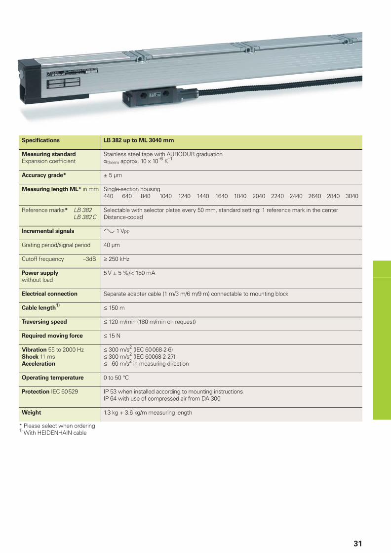
Specifi cations LB 382 up to ML 3040 mm
Measuring standard
Expansion coeffi cientStainless steel tape with AURODUR graduationÞtherm approx. 10 x 10–6 K–1
Accuracy grade* ± 5 µm
Measuring length ML* in mm Single-section housing440 640 840 1040 1240 1440 1640 1840 2040 2240 2440 2640 2840 3040
Reference marks* LB 382 LB 382C
Selectable with selector plates every 50 mm, standard setting: 1 reference mark in the centerDistance-coded
Incremental signals » 1 VPP
Grating period/signal period 40 µm
Cutoff frequency –3dB ‡ 250 kHz
Power supply
without load5 V ± 5 %/< 150 mA
Electrical connection Separate adapter cable (1 m/3 m/6 m/9 m) connectable to mounting block
Cable length1) † 150 m
Traversing speed † 120 m/min (180 m/min on request)
Required moving force † 15 N
Vibration 55 to 2000 HzShock 11 msAcceleration
† 300 m/s2 (IEC 60068-2-6)† 300 m/s2 (IEC 60068-2-27)† 60 m/s2 in measuring direction
Operating temperature 0 to 50 °C
Protection IEC 60529 IP 53 when installed according to mounting instructionsIP 64 with use of compressed air from DA 300
Weight 1.3 kg + 3.6 kg/m measuring length
* Please select when ordering1) With HEIDENHAIN cable
32
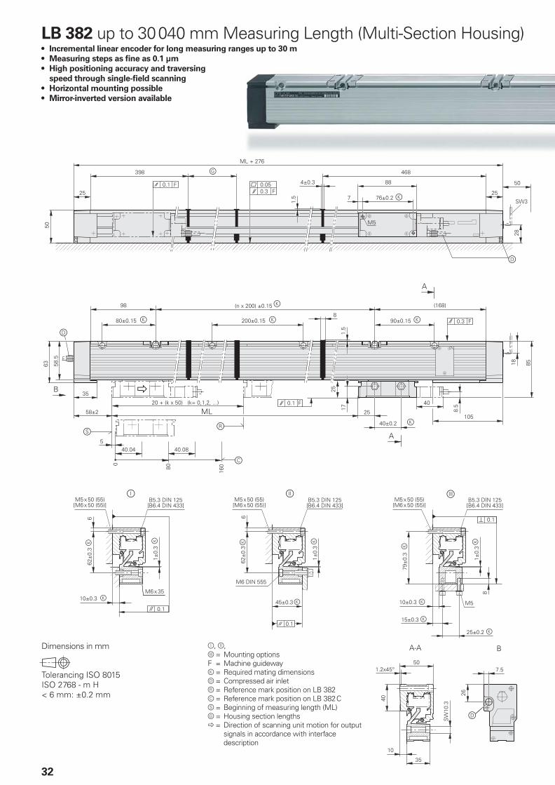
LB 382 up to 30040 mm Measuring Length (Multi-Section Housing)Incremental linear encoder for long measuring ranges up to 30 m
Measuring steps as fi ne as 0.1 µm
High positioning accuracy and traversing
speed through single-fi eld scanning
Horizontal mounting possible
Mirror-inverted version available
•
•
•
•
•
�
�
���� �
�����
����� ��
��
�� ���
$�
�
��� �
$
�#������������ �
������� �
� ����
"
��
������� �
�����
����
�
�
������
�����
�
�����
�
���
������� ��
���
�����+����������+,��-�--�����
���� �
����� ��
��
�������
��
��
������ �
��
�
�
�
�� � ���
����
���
���
���
�����
����� �
�����
��
�
�
����
���
��
�������������)������������*
�"���% &���)"����% &��*
����
��
���
�
������
���% &����
���
��
�������������)������������*
�"���% &���)"����% &��*
��
���
�
�������������)������������*
�"���% &���)"����% &��*
���
��
����
������������
Dimensions in mm
���� !"#$"%��&'���� �&'������(��)*���+������
Ô, Õ,Ö = Mounting optionsF = Machine guidewayk = Required mating dimensionsd = Compressed air inletr = Reference mark position on LB 382c = Reference mark position on LB 382Cs = Beginning of measuring length (ML)g = Housing section lengths� = Direction of scanning unit motion for output signals in accordance with interface description
�
�
"
���
��
�
��
�
���
��������
$'$
�
33
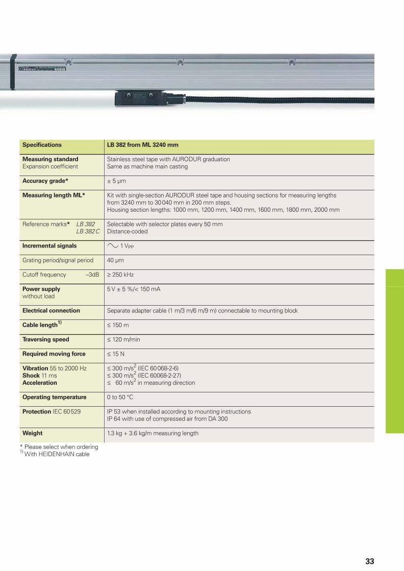
Specifi cations LB 382 from ML 3240 mm
Measuring standard
Expansion coeffi cientStainless steel tape with AURODUR graduationSame as machine main casting
Accuracy grade* ± 5 µm
Measuring length ML* Kit with single-section AURODUR steel tape and housing sections for measuring lengthsfrom 3240 mm to 30040 mm in 200 mm steps.Housing section lengths: 1000 mm, 1200 mm, 1400 mm, 1600 mm, 1800 mm, 2000 mm
Reference marks* LB 382 LB 382C
Selectable with selector plates every 50 mmDistance-coded
Incremental signals » 1 VPP
Grating period/signal period 40 µm
Cutoff frequency –3dB ‡ 250 kHz
Power supply
without load5 V ± 5 %/< 150 mA
Electrical connection Separate adapter cable (1 m/3 m/6 m/9 m) connectable to mounting block
Cable length1) † 150 m
Traversing speed † 120 m/min
Required moving force † 15 N
Vibration 55 to 2000 HzShock 11 msAcceleration
† 300 m/s2 (IEC 60068-2-6)† 300 m/s2 (IEC 60068-2-27)† 60 m/s2 in measuring direction
Operating temperature 0 to 50 °C
Protection IEC 60529 IP 53 when installed according to mounting instructionsIP 64 with use of compressed air from DA 300
Weight 1.3 kg + 3.6 kg/m measuring length
* Please select when ordering1) With HEIDENHAIN cable
34
Interfaces
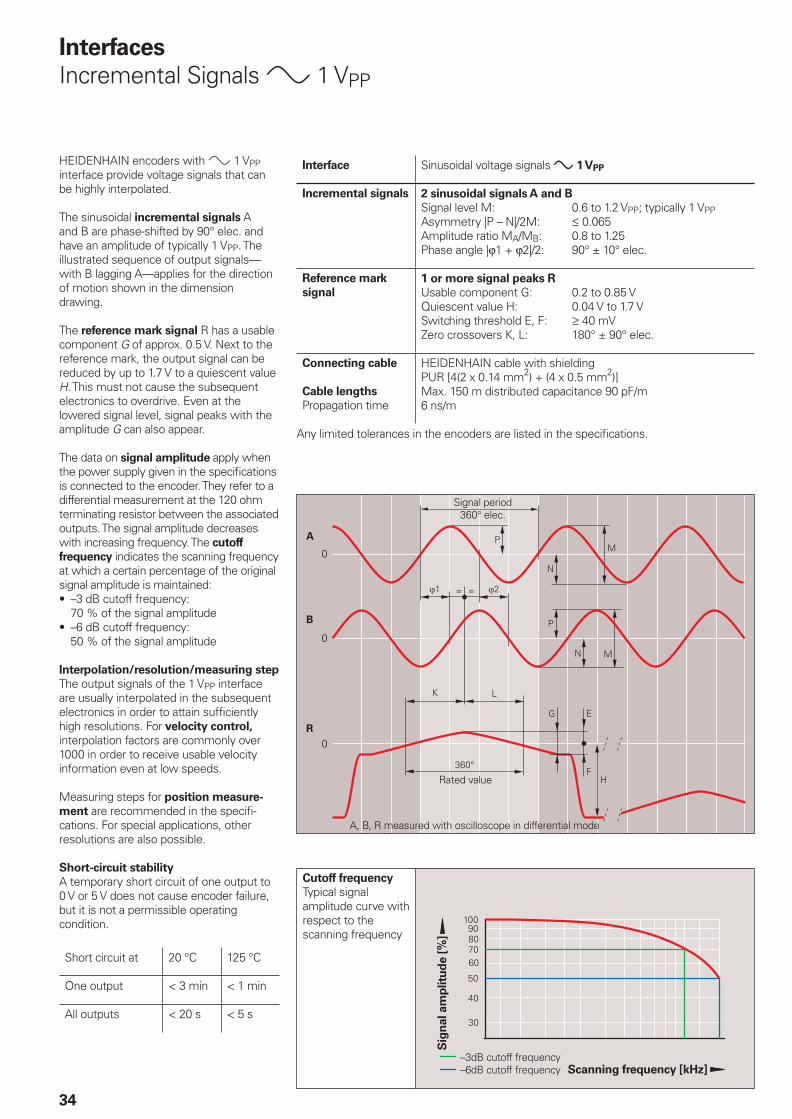
Incremental Signals » 1 VPP
HEIDENHAIN encoders with » 1 VPP interface provide voltage signals that can be highly interpolated.
The sinusoidal incremental signals A and B are phase-shifted by 90° elec. and have an amplitude of typically 1 VPP. The illustrated sequence of output signals—with B lagging A—applies for the direction of motion shown in the dimension drawing.
The reference mark signal R has a usable component G of approx. 0.5 V. Next to the reference mark, the output signal can be reduced by up to 1.7 V to a quiescent value H. This must not cause the subsequent electronics to overdrive. Even at the lowered signal level, signal peaks with the amplitude G can also appear.
The data on signal amplitude apply when the power supply given in the specifi cations is connected to the encoder. They refer to a differential measurement at the 120 ohm terminating resistor between the associated outputs. The signal amplitude decreases with increasing frequency. The cutoff
frequency indicates the scanning frequency at which a certain percentage of the original signal amplitude is maintained:
–3 dB cutoff frequency:70 % of the signal amplitude–6 dB cutoff frequency:50 % of the signal amplitude
Interpolation/resolution/measuring step
The output signals of the 1 VPP interface are usually interpolated in the subsequent electronics in order to attain suffi ciently high resolutions. For velocity control, interpolation factors are commonly over 1000 in order to receive usable velocity information even at low speeds.
Measuring steps for position measure-
ment are recommended in the specifi -cations. For special applications, other resolutions are also possible.
Short-circuit stability
A temporary short circuit of one output to 0 V or 5 V does not cause encoder failure, but it is not a permissible operating condition.
Short circuit at 20 °C 125 °C
One output < 3 min < 1 min
All outputs < 20 s < 5 s
•
•
Interface Sinusoidal voltage signals » 1 VPP
Incremental signals 2 sinusoidal signals A and B
Signal level M: 0.6 to 1.2 VPP; typically 1 VPPAsymmetry |P – N|/2M: † 0.065Amplitude ratio MA/MB: 0.8 to 1.25Phase angle |ϕ1 + ϕ2|/2: 90° ± 10° elec.
Reference mark
signal
1 or more signal peaks R
Usable component G: 0.2 to 0.85 VQuiescent value H: 0.04 V to 1.7 VSwitching threshold E, F: ‡ 40 mVZero crossovers K, L: 180° ± 90° elec.
Connecting cable
Cable lengths
Propagation time
HEIDENHAIN cable with shieldingPUR [4(2 x 0.14 mm2) + (4 x 0.5 mm2)]Max. 150 m distributed capacitance 90 pF/m6 ns/m
Any limited tolerances in the encoders are listed in the specifi cations.
Signal period360° elec.
Rated value
A, B, R measured with oscilloscope in differential mode
Cutoff frequency
Typical signal amplitude curve with respect to the scanning frequency
Sig
nal am
plitu
de [
%]
Scanning frequency [kHz]–3dB cutoff frequency–6dB cutoff frequency
35
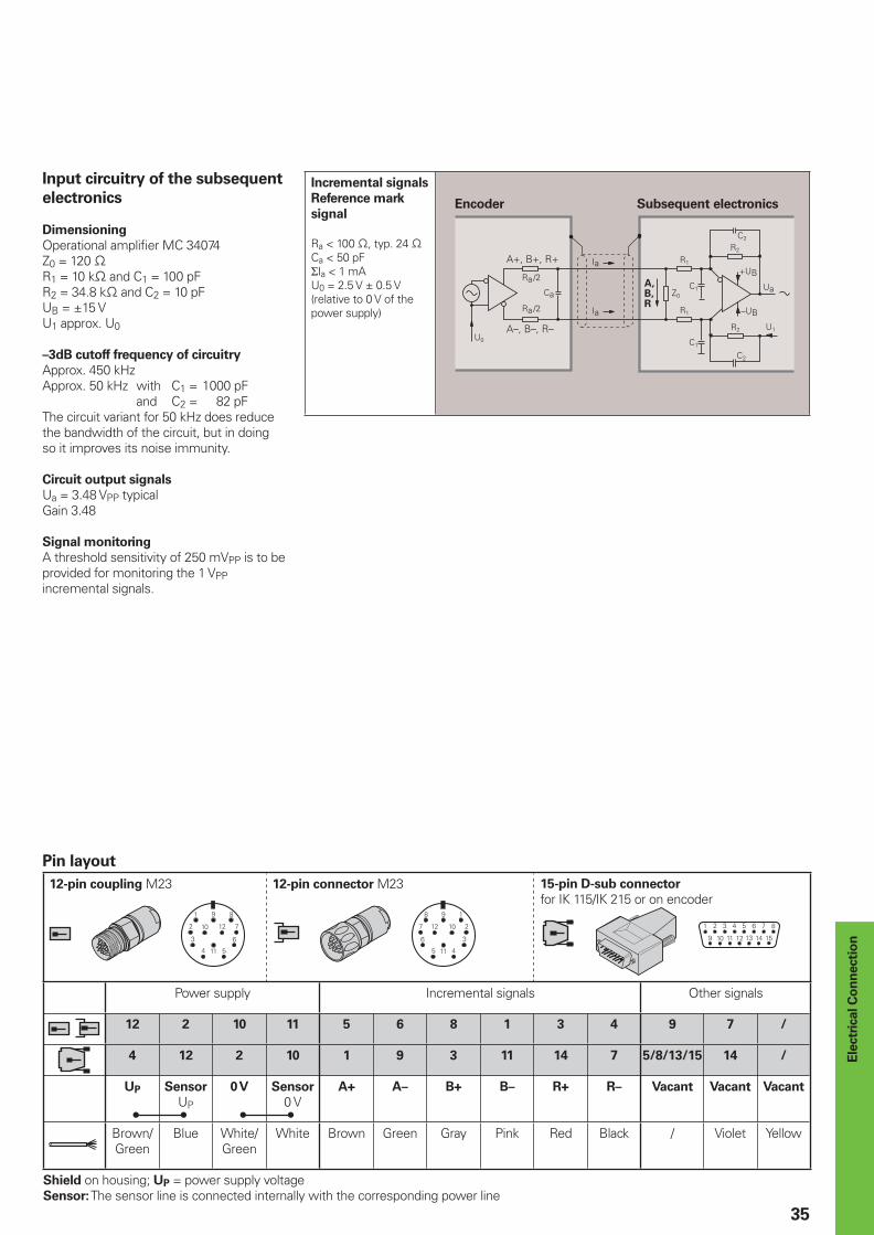
Input circuitry of the subsequent
electronics
Dimensioning
Operational amplifi er MC 34074Z0 = 120 −R1 = 10 k− and C1 = 100 pFR2 = 34.8 k− and C2 = 10 pFUB = ±15 VU1 approx. U0
–3dB cutoff frequency of circuitry
Approx. 450 kHzApprox. 50 kHz with C1 = 1000 pF and C2 = 82 pFThe circuit variant for 50 kHz does reduce the bandwidth of the circuit, but in doing so it improves its noise immunity.
Circuit output signals
Ua = 3.48 VPP typicalGain 3.48
Signal monitoring
A threshold sensitivity of 250 mVPP is to be provided for monitoring the 1 VPP incremental signals.
Incremental signals
Reference mark
signal
Ra < 100 −, typ. 24 −Ca < 50 pFΣIa < 1 mAU0 = 2.5 V ± 0.5 V(relative to 0 V of the power supply)
Encoder Subsequent electronics
Pin layout
12-pin coupling M23 12-pin connector M23 15-pin D-sub connector
for IK 115/IK 215 or on encoder
Power supply Incremental signals Other signals
12 2 10 11 5 6 8 1 3 4 9 7 /
4 12 2 10 1 9 3 11 14 7 5/8/13/15 14 /
UP Sensor
UP
0 V Sensor
0 VA+ A– B+ B– R+ R– Vacant Vacant Vacant
Brown/Green
Blue White/Green
White Brown Green Gray Pink Red Black / Violet Yellow
Shield on housing; UP = power supply voltageSensor: The sensor line is connected internally with the corresponding power line
Ele
ctr
ical C
on
necti
on
36
Interfaces
Absolute Position Values
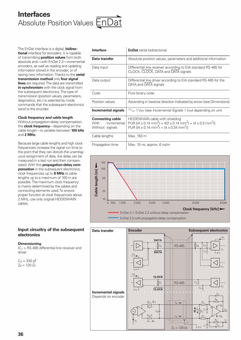
The EnDat interface is a digital, bidirec-
tional interface for encoders. It is capable of transmitting position values from both absolute and—with EnDat 2.2—incremental encoders, as well as reading and updating information stored in the encoder, or of saving new information. Thanks to the serial
transmission method only four signal
lines are required. The data are transmitted in synchronism with the clock signal from the subsequent electronics. The type of transmission (position values, parameters, diagnostics, etc.) is selected by mode commands that the subsequent electronics send to the encoder.
Clock frequency and cable length
Without propagation-delay compensation, the clock frequency—depending on the cable length—is variable between 100 kHz and 2 MHz.
Because large cable lengths and high clock frequencies increase the signal run time to the point that they can disturb the unambig-uous assignment of data, the delay can be measured in a test run and then compen-sated. With this propagation-delay com-
pensation in the subsequent electronics, clock frequencies up to 8 MHz at cable lengths up to a maximum of 100 m are possible. The maximum clock frequency is mainly determined by the cables and connecting elements used. To ensure proper function at clock frequencies above 2 MHz, use only original HEIDENHAIN cables.
Interface EnDat serial bidirectional
Data transfer Absolute position values, parameters and additional information
Data input Differential line receiver according to EIA standard RS 485 for CLOCK, CLOCK, DATA and DATA signals
Data output Differential line driver according to EIA standard RS 485 for the DATA and DATA signals
Code Pure binary code
Position values Ascending in traverse direction indicated by arrow (see Dimensions)
Incremental signals » 1 VPP (see Incremental Signals 1 VPP) depending on unit
Connecting cable HEIDENHAIN cable with shielding PUR [(4 x 0.14 mm2) + 4(2 x 0.14 mm2) + (4 x 0.5 mm2)]PUR [(4 x 0.14 mm2) + (4 x 0.34 mm2)]
WithWithout
incremental signals
Cable lengths Max. 150 m
Propagation time Max. 10 ns; approx. 6 ns/m
Input circuitry of the subsequent
electronics
Dimensioning
IC1 = RS 485 differential line receiver and driver
C3 = 330 pFZ0 = 120 −
Encoder Subsequent electronics
����� ������������������� ����� �����
Cab
le len
gth
[m
]
Clock frequency [kHz]EnDat 2.1; EnDat 2.2 without delay compensation
EnDat 2.2 with propagation-delay compensation
Data transfer
Incremental signals
Depends on encoder

37
Benefi ts of the EnDat InterfaceAutomatic self-confi guration: All information required by the subsequent electronics is already stored in the encoder High system security through alarms and messages for monitoring and diagnosis High transmission reliability through cyclic redundancy checking Faster confi guration during installation: Datum shifting through offsetting by a value in the encoder
Other benefi ts of EnDat 2.2
A single interface for all absolute and incremental encoders Additional information (limit switch, temperature, acceleration)Quality improvement: Position value calculation in the encoder permits shorter sampling intervals (25 µs)
Advantages of purely serial transmission
specifi cally for EnDat 2.2 encodersSimple subsequent electronics with EnDat receiver chipSimple connection technology: Standard connecting element (M12; 8-pin), single-shielded standard cable and few wiresMinimized transmission times through adaptation of the data word length to the resolution of the encoder High clock frequencies up to 8 MHz. Position values available in the subsequent electronics after only approx. 10 µsSupport for state-of-the-art machine
designs e.g. direct drive technology
•
•
•
•
•
•
•
•
•
•
•
•
Functions The EnDat interface transmits absolute position values or additional physical quantities (only EnDat 2.2) in an unambig-uous time sequence and serves to read from and write to the encoder‘s internal memory. Some functions are available only with EnDat 2.2 mode commands.
Position values can be transmitted with or without additional information. The additional information types are selectable via the Memory Range Select (MRS) code. Other functions such as parameter reading and writing can also be called after the memory area and address have been selected. Through simultaneous transmission with the position value, additional information can also be requested of axes in the feedback loop, and functions executed with them.
Parameter reading and writing is possible both as a separate function and in connec-tion with the position value. Parameters can be read or written after the memory area and address is selected.
Reset functions serve to reset the encoder in case of malfunction. Reset is possible instead of or during position value transmission.
Servicing diagnosis makes it possible to inspect the position value even at standstill. A test command has the encoder transmit the required test values.
You can fi nd more information in the Technical Information for EnDat 2.2 document or on the Internet at www.endat.de.
VersionsThe extended EnDat interface version 2.2 is compatible in its communication, command set and time conditions with version 2.1, but also offers signifi cant advantages. It makes it possible, for example, to transfer additional information with the position value without sending a separate request for it. The interface protocol was expanded and the time conditions (clock frequency, processing time, recovery time) were optimized. In addition, encoders with ordering designations EnDat 02 or EnDat 22 have an extended power supply range.
Both EnDat 2.1 and EnDat 2.2 are available in versions with or without incremental signals. EnDat 2.2 encoders feature a high internal resolution. Therefore, depending on the control technology being used, interrogation of the incremental signals is not necessary. To increase the resolution of EnDat 2.1 encoders, the incremental signals are evaluated in the subsequent electronics.
Command set
The command set is the sum of all available mode commands. The EnDat 2.2 command set includes EnDat 2.1 mode commands. When a mode command from the EnDat 2.2 command set is transmitted to EnDat-01 subsequent electronics, the encoder or the subsequent electronics may generate an error message.
EnDat with command set 2.2 (includes
EnDat 2.1 command set)
Position values for incremental and absolute encodersAdditional information on position value - Diagnostics and test values- Absolute position values after reference run of incremental encoders
- Parameter upload/download- Commutation- Acceleration- Limit position signal- Temperature of the encoder PCB- Temperature evaluation of an external temperature sensor (e.g. in the motor winding)
EnDat with command set 2.1
Absolute position valuesParameter upload/downloadResetTest command and test values
•
•
••••
Interface Command
set
Ordering
designation
Version Clock
frequency
EnDat EnDat 2.1 or EnDat 2.2
EnDat 01 With incremental signals † 2 MHz
EnDat 21 Without incremental signals
EnDat 2.2 EnDat 02 With incremental signals † 2 MHz
EnDat 2.2 EnDat 22 Without incremental signals † 8 MHz
38
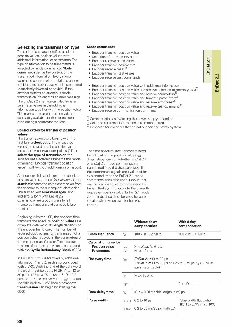
Selecting the transmission typeTransmitted data are identifi ed as either position values, position values with additional information, or parameters. The type of information to be transmitted is selected by mode commands. Mode
commands defi ne the content of the transmitted information. Every mode command consists of three bits. To ensure reliable transmission, every bit is transmitted redundantly (inverted or double). If the encoder detects an erroneous mode transmission, it transmits an error message. The EnDat 2.2 interface can also transfer parameter values in the additional information together with the position value. This makes the current position values constantly available for the control loop, even during a parameter request.
Control cycles for transfer of position
values
The transmission cycle begins with the fi rst falling clock edge. The measured values are saved and the position value calculated. After two clock pulses (2T), to select the type of transmission the subsequent electronics transmit the mode command ”Encoder transmit position value“ (with/without additional information).
After successful calculation of the absolute position value (tcal – see Specifi cations), the start bit initiates the data transmission from the encoder to the subsequent electronics. The subsequent error messages, error 1 and error 2 (only with EnDat 2.2 commands), are group signals for all monitored functions and serve as failure monitors.
Beginning with the LSB, the encoder then transmits the absolute position value as a complete data word. Its length depends on the encoder being used. The number of required clock pulses for transmission of a position value is saved in the parameters of the encoder manufacturer. The data trans-mission of the position value is completed with the Cyclic Redundancy Check (CRC).
In EnDat 2.2, this is followed by additional information 1 and 2, each also concluded with a CRC. With the end of the data word, the clock must be set to HIGH. After 10 to 30 µs or 1.25 to 3.75 µs (with EnDat 2.2 parameterizable recovery time tm) the data line falls back to LOW. Then a new data
transmission can begin by starting the clock.
Without delay
compensation
With delay
compensation
Clock frequency fc 100 kHz ... 2 MHz 100 kHz ... 8 MHz
Calculation time for
Position value
Parameters
tcaltac
See Specifi cationsMax. 12 ms
Recovery time tm EnDat 2.1: 10 to 30 µsEnDat 2.2: 10 to 30 µs or 1.25 to 3.75 µs (fc ‡ 1 MHz) (parameterizable)
tR Max. 500 ns
tST – 2 to 10 µs
Data delay time tD (0.2 + 0.01 x cable length in m) µs
Pulse width tHIGH
tLOW
0.2 to 10 µs
0.2 to 50 ms/30 µs (with LC)
Pulse width fl uctuationHIGH to LOW max. 10%
Mode commands
Encoder transmit position valueSelection of the memory areaEncoder receive parametersEncoder transmit parametersEncoder receive reset1)
Encoder transmit test valuesEncoder receive test commands
•••••••
En
Dat
2.1
En
Dat
2.2
Encoder transmit position value with additional informationEncoder transmit position value and receive selection of memory area2)
Encoder transmit position value and receive parameters2)
Encoder transmit position value and transmit parameters2)
Encoder transmit position value and receive error reset2)
Encoder transmit position value and receive test command2)
Encoder receive communication command3)
•••••••
1) Same reaction as switching the power supply off and on2) Selected additional information is also transmitted3) Reserved for encoders that do not support the safety system
The time absolute linear encoders need for calculating the position values tcal differs depending on whether EnDat 2.1 or EnDat 2.2 mode commands are transmitted (see the Specifi cations). If the incremental signals are evaluated for axis control, then the EnDat 2.1 mode commands should be used. Only in this manner can an active error message be transmitted synchronously to the currently requested position value. EnDat 2.1 mode commands should not be used for pure serial position-value transfer for axis control.
39
/#!�
� �
/&�
� �� ��
/ /0
Encoder saves position value
Subsequent electronics transmit mode command
Mode command Position value CRC
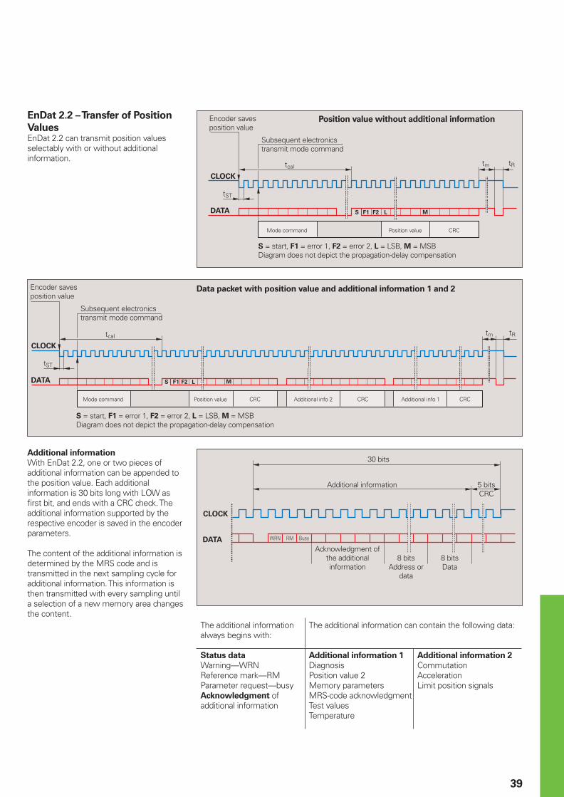
S = start, F1 = error 1, F2 = error 2, L = LSB, M = MSBDiagram does not depict the propagation-delay compensation
Position value without additional informationEnDat 2.2 – Transfer of Position
ValuesEnDat 2.2 can transmit position values selectably with or without additional information.
/#!� /
� �
/&�
/0
� �� ��
Encoder saves position value
Subsequent electronics transmit mode command
Mode command Position value CRC Additional info 2 CRC Additional info 1 CRC
S = start, F1 = error 1, F2 = error 2, L = LSB, M = MSBDiagram does not depict the propagation-delay compensation
Additional information
With EnDat 2.2, one or two pieces of additional information can be appended to the position value. Each additional information is 30 bits long with LOW as fi rst bit, and ends with a CRC check. The additional information supported by the respective encoder is saved in the encoder parameters.
The content of the additional information is determined by the MRS code and is transmitted in the next sampling cycle for additional information. This information is then transmitted with every sampling until a selection of a new memory area changes the content.
The additional information always begins with:
The additional information can contain the following data:
Status data
Warning—WRN Reference mark—RM Parameter request—busyAcknowledgment of additional information
Additional information 1
Diagnosis Position value 2Memory parameters MRS-code acknowledgmentTest values Temperature
Additional information 2
Commutation AccelerationLimit position signals
12340�50�
30 bits
Additional information 5 bitsCRC
Acknowledgment of the additional information
8 bits Address or
data
8 bits Data
Data packet with position value and additional information 1 and 2
40
EnDat 2.1 – Transfer of Position
ValuesEnDat 2.1 can transmit position values selectably with interrupted clock pulse (as in EnDat 2.2) or continuous clock pulse.
Interrupted clock
The interrupted clock is intended particularly for time-clocked systems such as closed control loops. At the end of the data word the clock signal is set to HIGH level. After 10 to 30 µs (tm), the data line falls back to LOW. Then a new data transmission can begin by starting the clock.
Continuous clock
For applications that require fast acquisition of the measured value, the EnDat interface can have the clock run continuously. Immediately after the last CRC bit has been sent, the data line is switched to high for one clock cycle, and then to low. The new position value is saved with the very next falling edge of the clock and is output in synchronism with the clock signal immediately after the start bit and alarm bit. Because the mode command Encoder transmit position value is needed only before the fi rst data transmission, the continuous-clock transfer mode reduces the length of the clock-pulse group by 9 periods per position value.
Synchronization of the serially
transmitted code value with the
incremental signal
Absolute encoders with EnDat interface can exactly synchronize serially transmitted absolute position values with incremental values. With the fi rst falling edge (latch signal) of the CLOCK signal from the subsequent electronics, the scanning signals of the individual tracks in the encoder and counter are frozen, as are also the A/D converters for subdividing the sinusoidal incremental signals in the subsequent electronics.
The code value transmitted over the serial interface unambiguously identifi es one incremental signal period. The position value is absolute within one sinusoidal period of the incremental signal. The subdivided incremental signal can therefore be appended in the subsequent electronics to the serially transmitted code value.
Encoder Subsequent electronics
Latch signal
Subdivision
Counter Co
mp
ara
tor
Parallel interface
1 VPP
1 VPP
After power on and initial transmission of position values, two redundant position values are available in the subsequent electronics. Since encoders with EnDat interface guarantee a precise synchro-nization—regardless of cable length—of the serially transmitted absolute value with
Position value CRCCRC
Save new position value
Save new position value
n = 0 to 7; depending on system Continuous clock
the incremental signals, the two values can be compared in the subsequent electronics. This monitoring is possible even at high shaft speeds thanks to the EnDat interface’s short transmission times of less than 50 µs. This capability is a prerequisite for modern machine design and safety systems.
Encoder saves position value
Subsequent electronics transmit mode command
Mode command Position value Cyclic Redundancy Check
Interrupted clock
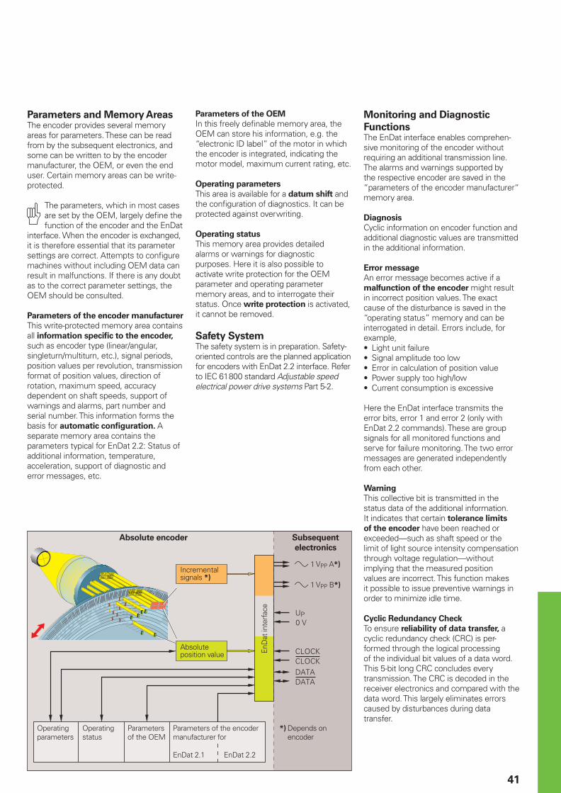
41
Parameters and Memory AreasThe encoder provides several memory areas for parameters. These can be read from by the subsequent electronics, and some can be written to by the encoder manufacturer, the OEM, or even the end user. Certain memory areas can be write-protected.
The parameters, which in most cases are set by the OEM, largely defi ne the function of the encoder and the EnDat
interface. When the encoder is exchanged, it is therefore essential that its parameter settings are correct. Attempts to confi gure machines without including OEM data can result in malfunctions. If there is any doubt as to the correct parameter settings, the OEM should be consulted.
Parameters of the encoder manufacturer
This write-protected memory area contains all information specifi c to the encoder, such as encoder type (linear/angular, singleturn/multiturn, etc.), signal periods, position values per revolution, transmission format of position values, direction of rotation, maximum speed, accuracy dependent on shaft speeds, support of warnings and alarms, part number and serial number. This information forms the basis for automatic confi guration. A separate memory area contains the parameters typical for EnDat 2.2: Status of additional information, temperature, acceleration, support of diagnostic and error messages, etc.
Absolute encoder Subsequent
electronics
Absolute position value
Operating parameters
Operating status
Parameters of the OEM
Parameters of the encoder manufacturer for
EnDat 2.1 EnDat 2.2
EnD
at in
terf
ace
Monitoring and Diagnostic
Functions The EnDat interface enables comprehen-sive monitoring of the encoder without requiring an additional transmission line. The alarms and warnings supported by the respective encoder are saved in the “parameters of the encoder manufacturer“ memory area.
Diagnosis
Cyclic information on encoder function and additional diagnostic values are transmitted in the additional information.
Error message
An error message becomes active if a malfunction of the encoder might result in incorrect position values. The exact cause of the disturbance is saved in the “operating status” memory and can be interrogated in detail. Errors include, for example,
Light unit failureSignal amplitude too lowError in calculation of position valuePower supply too high/lowCurrent consumption is excessive
Here the EnDat interface transmits the error bits, error 1 and error 2 (only with EnDat 2.2 commands). These are group signals for all monitored functions and serve for failure monitoring. The two error messages are generated independently from each other.
Warning
This collective bit is transmitted in the status data of the additional information. It indicates that certain tolerance limits
of the encoder have been reached or exceeded—such as shaft speed or the limit of light source intensity compensation through voltage regulation—without implying that the measured position values are incorrect. This function makes it possible to issue preventive warnings in order to minimize idle time.
Cyclic Redundancy Check
To ensure reliability of data transfer, a cyclic redundancy check (CRC) is per-formed through the logical processing of the individual bit values of a data word. This 5-bit long CRC concludes every transmission. The CRC is decoded in the receiver electronics and compared with the data word. This largely eliminates errors caused by disturbances during data transfer.
•••••
Incremental signals *)
*) Depends on encoder
» 1 VPP A*)
» 1 VPP B*)
Parameters of the OEM
In this freely defi nable memory area, the OEM can store his information, e.g. the “electronic ID label” of the motor in which the encoder is integrated, indicating the motor model, maximum current rating, etc.
Operating parameters
This area is available for a datum shift and the confi guration of diagnostics. It can be protected against overwriting.
Operating status
This memory area provides detailed alarms or warnings for diagnostic purposes. Here it is also possible to activate write protection for the OEM parameter and operating parameter memory areas, and to interrogate their status. Once write protection is activated, it cannot be removed.
Safety SystemThe safety system is in preparation. Safety-oriented controls are the planned application for encoders with EnDat 2.2 interface. Refer to IEC 61800 standard Adjustable speed electrical power drive systems Part 5-2.
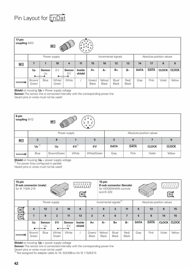
42
Pin Layout for
17-pin
coupling M23
Power supply Incremental signals Absolute position values
7 1 10 4 11 15 16 12 13 14 17 8 9
UP Sensor
UP
0 V Sensor
0 VInside
shield
A+ A– B+ B– DATA DATA CLOCK CLOCK
Brown/Green
Blue White/Green
White / Green/Black
Yellow/Black
Blue/Black
Red/Black
Gray Pink Violet Yellow
Shield on housing; UP = Power supply voltageSensor: The sensor line is connected internally with the corresponding power lineVacant pins or wires must not be used!
15-pin
D-sub connector (male)
for IK 115/IK 215
15-pin
D-sub connector (female)
for HEIDENHAIN controlsand IK 220
Power supply Incremental signals1) Absolute position values
4 12 2 10 6 1 9 3 11 5 13 8 15
1 9 2 11 13 3 4 6 7 5 8 14 15
UP Sensor
UP
0 V Sensor
0 VInside
shield
A+ A– B+ B– DATA DATA CLOCK CLOCK
Brown/Green
Blue White/Green
White / Green/Black
Yellow/Black
Blue/Black
Red/Black
Gray Pink Violet Yellow
Shield on housing; UP = power supply voltageSensor: The sensor line is connected internally with the corresponding power lineVacant pins or wires must not be used!1) Not assigned for adapter cable Id. Nr. 524599-xx for IK 115/IK215
8-pin
coupling M12
Power supply Absolute position values
2 8 1 5 3 4 7 6
UP 1)
UP 0 V1)
0 V DATA DATA CLOCK CLOCK
Blue Brown/Green White White/Green Gray Pink Violet Yellow
Shield on housing; UP = power supply voltage1) For power lines confi gured in parallelVacant pins or wires must not be used!
�
�
��
�
��
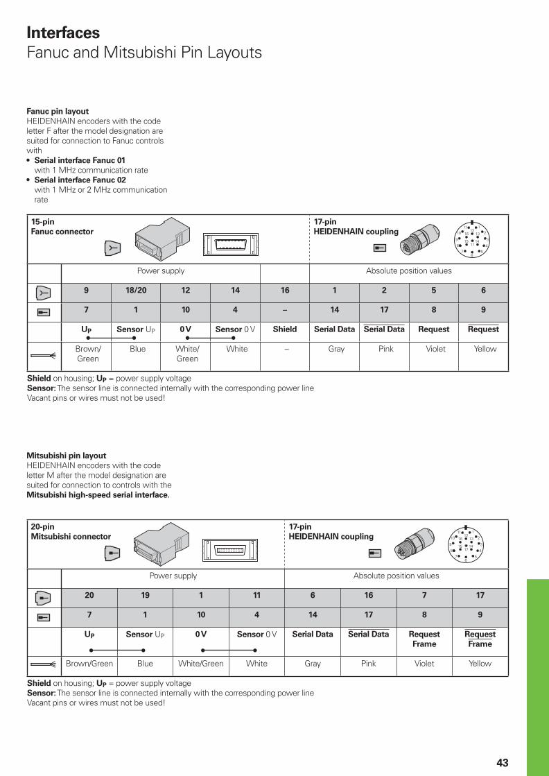
43
15-pin
Fanuc connector
17-pin
HEIDENHAIN coupling
Power supply Absolute position values
9 18/20 12 14 16 1 2 5 6
7 1 10 4 – 14 17 8 9
UP Sensor UP 0 V Sensor 0 V Shield Serial Data Serial Data Request Request
Brown/Green
Blue White/Green
White – Gray Pink Violet Yellow
Shield on housing; UP = power supply voltageSensor: The sensor line is connected internally with the corresponding power lineVacant pins or wires must not be used!
Interfaces
Fanuc and Mitsubishi Pin Layouts
Fanuc pin layout
HEIDENHAIN encoders with the code letter F after the model designation are suited for connection to Fanuc controls with
Serial interface Fanuc 01
with 1 MHz communication rateSerial interface Fanuc 02
with 1 MHz or 2 MHz communication rate
•
•
Mitsubishi pin layout
HEIDENHAIN encoders with the code letter M after the model designation are suited for connection to controls with the Mitsubishi high-speed serial interface.
20-pin
Mitsubishi connector
17-pin
HEIDENHAIN coupling
Power supply Absolute position values
20 19 1 11 6 16 7 17
7 1 10 4 14 17 8 9
UP Sensor UP 0 V Sensor 0 V Serial Data Serial Data Request
Frame
Request
Frame
Brown/Green Blue White/Green White Gray Pink Violet Yellow
Shield on housing; UP = power supply voltageSensor: The sensor line is connected internally with the corresponding power lineVacant pins or wires must not be used!
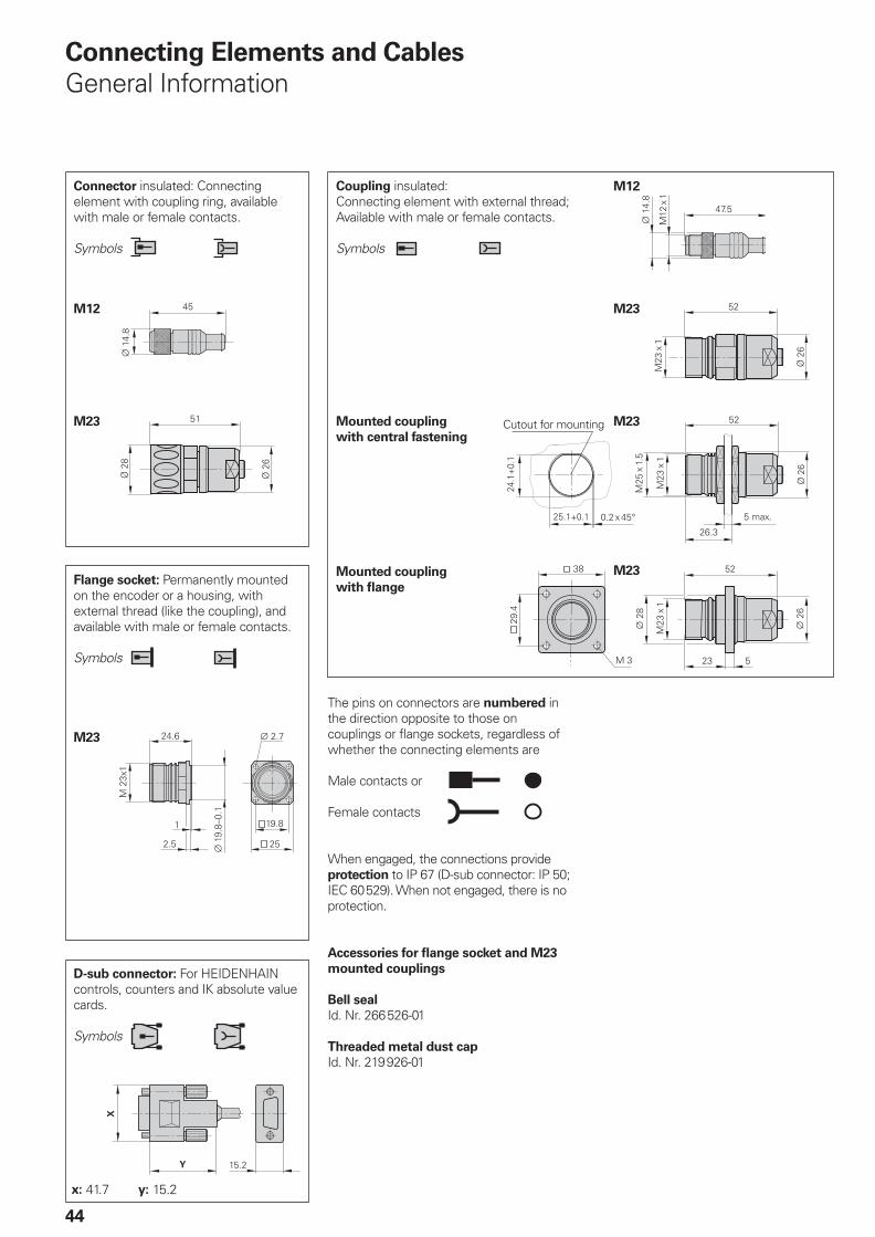
44
The pins on connectors are numbered in the direction opposite to those on couplings or fl ange sockets, regardless of whether the connecting elements are
Male contacts or
Female contacts
When engaged, the connections provide protection to IP 67 (D-sub connector: IP 50; IEC 60529). When not engaged, there is no protection.
Accessories for fl ange socket and M23
mounted couplings
Bell seal
Id. Nr. 266526-01
Threaded metal dust cap
Id. Nr. 219926-01
Connecting Elements and Cables
General Information
Connector insulated: Connecting element with coupling ring, available with male or female contacts.
Symbols
Coupling insulated: Connecting element with external thread; Available with male or female contacts.
Symbols
D-sub connector: For HEIDENHAIN controls, counters and IK absolute value cards.
Symbols
Flange socket: Permanently mounted on the encoder or a housing, with external thread (like the coupling), and available with male or female contacts.
Symbols
M23
M23
M23
M23
Mounted coupling
with central fastening
Mounted coupling
with fl ange
x: 41.7 y: 15.2
Cutout for mounting M23
M12
M12
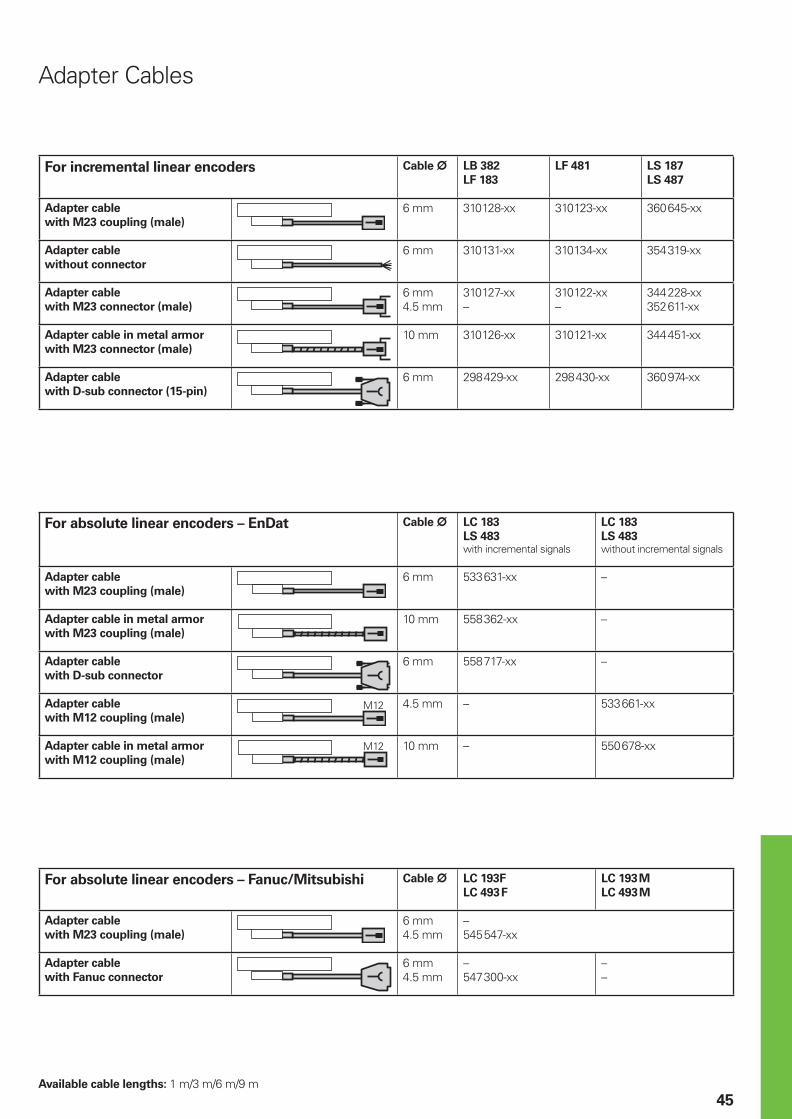
45
Adapter Cables
For incremental linear encoders Cable ¬ LB 382
LF 183
LF 481 LS 187
LS 487
Adapter cable
with M23 coupling (male)
6 mm 310128-xx 310123-xx 360645-xx
Adapter cable
without connector
6 mm 310131-xx 310134-xx 354319-xx
Adapter cable
with M23 connector (male)
6 mm4.5 mm
310127-xx–
310122-xx–
344228-xx352611-xx
Adapter cable in metal armor
with M23 connector (male)
10 mm 310126-xx 310121-xx 344451-xx
Adapter cable
with D-sub connector (15-pin)
6 mm 298429-xx 298430-xx 360974-xx
For absolute linear encoders – Fanuc/Mitsubishi Cable ¬ LC 193F
LC 493F
LC 193M
LC 493M
Adapter cable
with M23 coupling (male)
6 mm4.5 mm
–545547-xx
Adapter cable
with Fanuc connector
6 mm4.5 mm
–547300-xx
––
Available cable lengths: 1 m/3 m/6 m/9 m
For absolute linear encoders – EnDat Cable ¬ LC 183
LS 483with incremental signals
LC 183
LS 483without incremental signals
Adapter cable
with M23 coupling (male)
6 mm 533631-xx –
Adapter cable in metal armor
with M23 coupling (male)
10 mm 558362-xx –
Adapter cable
with D-sub connector
6 mm 558717-xx –
Adapter cable
with M12 coupling (male)
4.5 mm – 533661-xx
Adapter cable in metal armor
with M12 coupling (male)
10 mm – 550678-xx
M12
M12
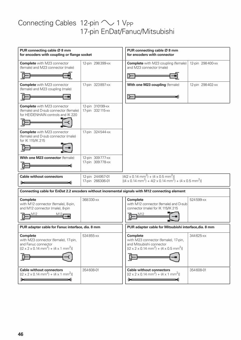
46
Connecting Cables 12-pin » 1 VPP 17-pin EnDat/Fanuc/Mitsubishi
PUR connecting cable ¬ 8 mm
for encoders with coupling or fl ange socket
PUR connecting cable ¬ 8 mm
for encoders with connector
Complete with M23 connector (female) and M23 connector (male)
12-pin 298399-xx Complete with M23 coupling (female) and M23 connector (male)
12-pin 298400-xx
Complete with M23 connector (female) and M23 coupling (male)
17-pin 323897-xx With one M23 coupling (female) 12-pin 298402-xx
Complete with M23 connector (female) and D-sub connector (female) for HEIDENHAIN controls and IK 220
12-pin 310199-xx17-pin 332115-xx
Complete with M23 connector (female) and D-sub connector (male) for IK 115/IK 215
17-pin 324544-xx
With one M23 connector (female) 12-pin 309777-xx17-pin 309778-xx
Cable without connectors 12-pin 244957-01 [4(2 x 0.14 mm2) + (4 x 0.5 mm2)]17-pin 266306-01 [(4 x 0.14 mm2) + 4(2 x 0.14 mm2) + (4 x 0.5 mm2)]
Connecting cable for EnDat 2.2 encoders without incremental signals with M12 connecting element
Complete
with M12 connector (female), 8-pin, and M12 connector (male), 8-pin
368330-xx Complete
with M12 connector (female) and D-sub connector (male) for IK 115/IK 215
524599-xx
PUR adapter cable for Fanuc interface, dia. 8 mm PUR adapter cable for Mitsubishi interface,dia. 8 mm
Complete
with M23 connector (female), 17-pin, and Fanuc connector[(2 x 2 x 0.14 mm2) + (4 x 1 mm2)]
534855-xx Complete
with M23 connector (female), 17-pin, and Mitsubishi connector[(2 x 2 x 0.14 mm2) + (4 x 0.5 mm2)]
344625-xx
Cable without connectors
[(2 x 2 x 0.14 mm2) + (4 x 1 mm2)]354608-01 Cable without connectors
[(2 x 2 x 0.14 mm2) + (4 x 1 mm2)]354608-01
M12 M12 M12
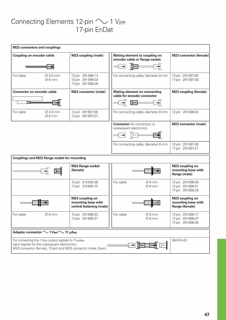
47
Connecting Elements 12-pin » 1 VPP 17-pin EnDat
M23 connectors and couplings
Coupling on encoder cable M23 coupling (male) Mating element to coupling on
encoder cable or fl ange socket
M23 connector (female)
For cable ¬ 4.5 mm ¬ 6 mm
12-pin 291698-1412-pin 291698-0317-pin 291698-26
For connecting cable, diameter 8 mm 12-pin 291697-0517-pin 291697-26
Connector on encoder cable M23 connector (male) Mating element on connecting
cable for encoder connector
M23 coupling (female)
For cable ¬ 4.5 mm ¬ 6 mm
12-pin 291697-0612-pin 291697-07
For connecting cable, diameter 8 mm 12-pin 291698-02
Connector for connection to subsequent electronics
M23 connector (male)
For connecting cable, diameter 8 mm 12-pin 291697-0817-pin 291697-27
Couplings and M23 fl ange socket for mounting
M23 fl ange socket
(female)
M23 coupling on
mounting base with
fl ange (male)
12-pin 315892-0817-pin 315892-10
For cable ¬ 6 mm ¬ 8 mm
12-pin 291698-0812-pin 291698-3117-pin 291698-29
M23 coupling on
mounting base with
central fastening (male)
M23 coupling on
mounting base with
fl ange (female)
For cable ¬ 6 mm 12-pin 291698-3317-pin 291698-37
For cable ¬ 6 mm ¬ 8 mm
12-pin 291698-1712-pin 291698-0717-pin 291698-35
Adapter connector » 1 VPP/» 11 µAPP
For converting the 1-VPP output signals to 11-µAPPinput signals for the subsequent electronics;M23 connector (female, 12-pin) and M23 connector (male, 9-pin)
364914-01
48
General Electrical Information
Power Supply
The encoders require a stabilized dc
voltage UP as power supply. The respective specifi cations state the required power supply and the current consumption. The permissible ripple content of the dc voltage is:
High frequency interferenceUPP < 250 mV with dU/dt > 5 V/µsLow frequency fundamental rippleUPP < 100 mV
•
•
The values apply as measured at the encoder, i.e., without cable infl uences. The voltage can be monitored and adjusted with the device‘s sensor lines. If a controllable power supply is not available, the voltage drop can be halved by switching the sensor lines parallel to the corresponding power lines.
Calculation of the voltage drop:
¹U = 2 · 10–3 ·
with ¹U: Voltage attenuation in V LC: Cable length in m I: Current consumption of the
encoder in mA (see Specifi cations) AP: Cross section of power lines in
mm2
HEIDENHAIN
cables
Cross section of power supply lines AP
1 VPP/TTL/HTL 11 µAPP EnDat/SSI
17-pinEnDat
8-pin
¬ 3.7 mm 0.05 mm2 – – –
¬ 4.5/5.1 mm 0.14/0.052) mm2 0.05 mm2 0.05 mm2 –
¬ 6/101)
mm 0.19/ 0.143) mm2 – 0.08 mm2 0.34 mm2
¬ 8/141)
mm 0.5 mm2 1 mm2 0.5 mm2 1 mm2
Electrically Permissible Speed/
Traversing Speed
The maximum permissible shaft speed or traversing velocity of an encoder is derived from
the mechanically permissible shaft speed or traversing velocity (if listed in Specifi cations) and the electrically permissible shaft speed or traversing velocity.
For encoders with sinusoidal output
signals, the electrically permissible shaft speed or traversing velocity is limited by the –3dB/ –6dB cutoff frequency or the permissible input frequency of the subsequent electronics.For encoders with square-wave signals, the electrically permissible shaft speed or traversing velocity is limited by– the maximum permissible scanning/ output frequency fmax of the encoder and– the minimum permissible edge separation a for the subsequent electronics
For angular or rotary encoders
nmax = · 60 · 103
For linear encoders
vmax = fmax · SP · 60 · 10–3
where nmax: Electrically permissible speed in rpm vmax: Electrically permissible speed in m/min fmax: Maximum scanning/output frequency of the encoder or input frequency of the subsequent electronics in kHz z: Line count of the angle or rotary encoder per 360° SP: Signal period of the linear encoder in µm
•
•
Cables
Lengths
The cable lengths listed in the Specifi cations apply only for HEIDENHAIN cables and the recommended input circuitry of subsequent electronics.
Durability
All encoders have polyurethane (PUR) cables. PUR cables are resistant to oil, hydrolysis and microbes in accordance with VDE 0472. They are free of PVC and silicone and comply with UL safety directives. The UL certifi cation AWM STYLE 20963 80 °C 30 V E63216 is documented on the cable.
Temperature range
HEIDENHAIN cables can be used:for stationary cables –40 to 85 °Cfor moving cables –10 to 85 °C
Cables with limited resistance to hydrolysis and microbes are rated for up to 100 °C (except cables with M12 connecting elements).
Bending radius
The permissible bending radii R depend on the cable diameter and the confi guration:
HEIDENHAIN
cables
Stationary
cable
Moving
cable
¬ 3.7 mm R ‡ 8 mm R ‡ 40 mm
¬ 4.5 mm
¬ 5.1 mm
R ‡ 10 mm R ‡ 50 mm
¬ 6 mm R ‡ 20 mm R ‡ 75 mm
¬ 8 mm R ‡ 40 mm R ‡ 100 mm
¬ 10 mm1) R ‡ 35 mm R ‡ 75 mm
¬ 14 mm1) R ‡ 50 mm R ‡ 100 mm
LC · I56 · AP
fmaxz
Initial transient response of the
supply voltage e.g. 5 V ± 5 %
Typically 500 ms
Stationary cable
Moving cable
Moving cable
1) Metal armor2) Only on
length gauges3) Only for
LIDA 400
UPP
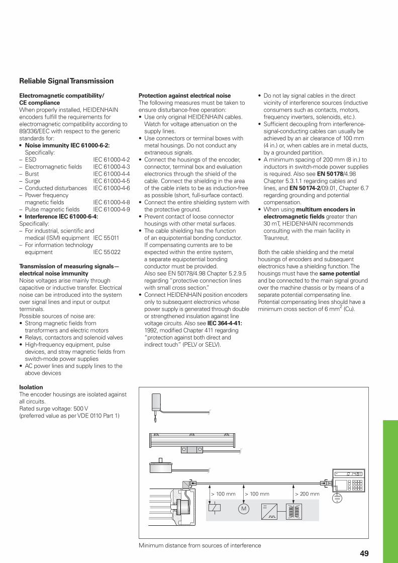
49
Reliable Signal Transmission
Electromagnetic compatibility/
CE compliance
When properly installed, HEIDENHAIN encoders fulfi ll the requirements for electromagnetic compatibility according to 89/336/EEC with respect to the generic standards for:
Noise immunity IEC 61000-6-2:
Specifi cally:– ESD IEC 61000-4-2– Electromagnetic fi elds IEC 61000-4-3– Burst IEC 61000-4-4– Surge IEC 61000-4-5– Conducted disturbances IEC 61000-4-6– Power frequency magnetic fi elds IEC 61000-4-8– Pulse magnetic fi elds IEC 61000-4-9
Interference IEC 61000-6-4:
Specifi cally:– For industrial, scientifi c and medical (ISM) equipment IEC 55011– For information technology equipment IEC 55022
Transmission of measuring signals—
electrical noise immunity
Noise voltages arise mainly through capacitive or inductive transfer. Electrical noise can be introduced into the system over signal lines and input or output terminals.Possible sources of noise are:
Strong magnetic fi elds from transformers and electric motorsRelays, contactors and solenoid valvesHigh-frequency equipment, pulse devices, and stray magnetic fi elds from switch-mode power suppliesAC power lines and supply lines to the above devices
Isolation
The encoder housings are isolated against all circuits.Rated surge voltage: 500 V(preferred value as per VDE 0110 Part 1)
•
•
•
••
•
Protection against electrical noise
The following measures must be taken to ensure disturbance-free operation:
Use only original HEIDENHAIN cables. Watch for voltage attenuation on the supply lines.Use connectors or terminal boxes with metal housings. Do not conduct any extraneous signals.Connect the housings of the encoder, connector, terminal box and evaluation electronics through the shield of the cable. Connect the shielding in the area of the cable inlets to be as induction-free as possible (short, full-surface contact).Connect the entire shielding system with the protective ground.Prevent contact of loose connector housings with other metal surfaces.The cable shielding has the function of an equipotential bonding conductor. If compensating currents are to be expected within the entire system, a separate equipotential bonding conductor must be provided.Also see EN 50178/4.98 Chapter 5.2.9.5 regarding “protective connection lines with small cross section.”Connect HEIDENHAIN position encoders only to subsequent electronics whose power supply is generated through double or strengthened insulation against line voltage circuits. Also see IEC 364-4-41: 1992, modifi ed Chapter 411 regarding “protection against both direct and indirect touch” (PELV or SELV).
•
•
•
•
•
•
•
Do not lay signal cables in the direct vicinity of interference sources (inductive consumers such as contacts, motors, frequency inverters, solenoids, etc.).Suffi cient decoupling from interference-signal-conducting cables can usually be achieved by an air clearance of 100 mm (4 in.) or, when cables are in metal ducts, by a grounded partition.A minimum spacing of 200 mm (8 in.) to inductors in switch-mode power supplies is required. Also see EN 50178/4.98 Chapter 5.3.1.1 regarding cables and lines, and EN 50174-2/09.01, Chapter 6.7 regarding grounding and potential compensation.When using multiturn encoders in
electromagnetic fi elds greater than 30 mT, HEIDENHAIN recommends consulting with the main facility in Traunreut.
Both the cable shielding and the metal housings of encoders and subsequent electronics have a shielding function. The housings must have the same potential
and be connected to the main signal ground over the machine chassis or by means of a separate potential compensating line. Potential compensating lines should have a minimum cross section of 6 mm2 (Cu).
•
•
•
•
Minimum distance from sources of interference
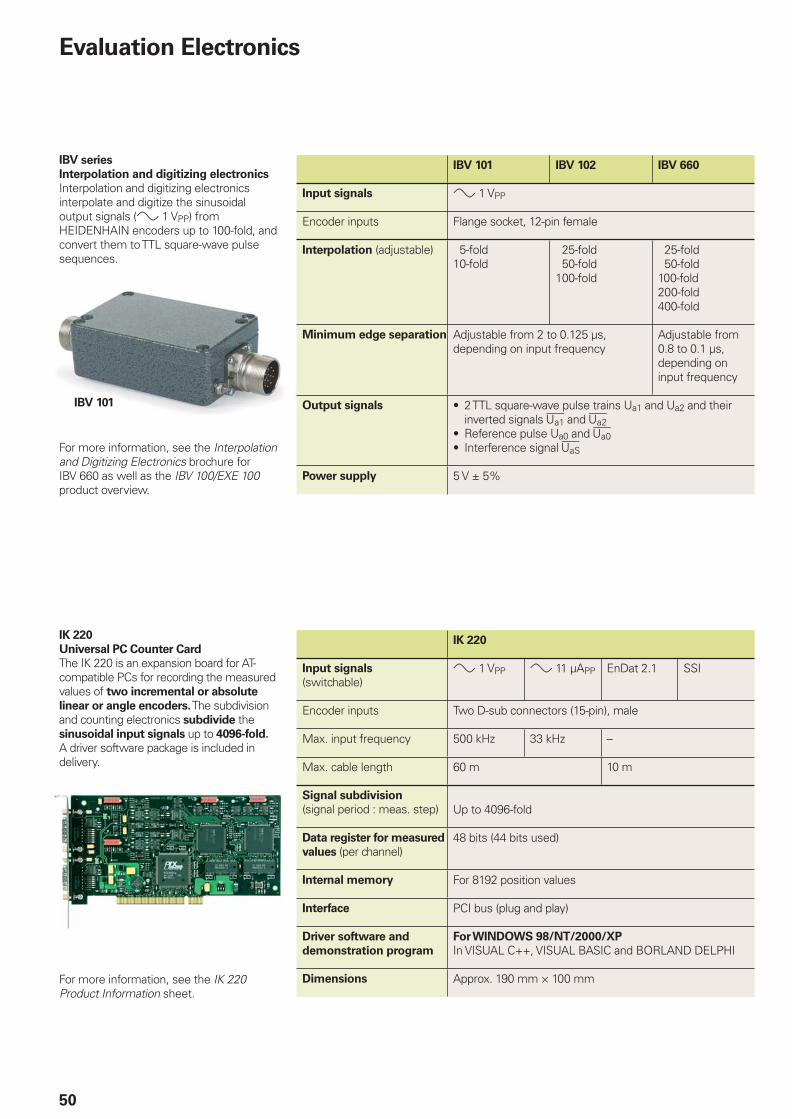
50
IBV series
Interpolation and digitizing electronics
Interpolation and digitizing electronics interpolate and digitize the sinusoidal output signals (» 1 VPP) from HEIDENHAIN encoders up to 100-fold, and convert them to TTL square-wave pulse sequences.
For more information, see the Interpolation and Digitizing Electronics brochure for IBV 660 as well as the IBV 100/EXE 100 product overview.
IBV 101 IBV 102 IBV 660
Input signals » 1 VPP
Encoder inputs Flange socket, 12-pin female
Interpolation (adjustable) 5-fold10-fold
25-fold 50-fold100-fold
25-fold 50-fold100-fold200-fold400-fold
Minimum edge separation Adjustable from 2 to 0.125 µs,depending on input frequency
Adjustable from 0.8 to 0.1 µs,depending on input frequency
Output signals 2 TTL square-wave pulse trains Ua1 and Ua2 and their inverted signals � and £Reference pulse Ua0 and ¤Interference signal ¥
•
••
Power supply 5 V ± 5%
IBV 101
IK 220
Universal PC Counter Card
The IK 220 is an expansion board for AT-compatible PCs for recording the measured values of two incremental or absolute
linear or angle encoders. The subdivision and counting electronics subdivide the sinusoidal input signals up to 4096-fold. A driver software package is included in delivery.
For more information, see the IK 220 Product Information sheet.
IK 220
Input signals
(switchable)» 1 VPP » 11 µAPP EnDat 2.1 SSI
Encoder inputs Two D-sub connectors (15-pin), male
Max. input frequency 500 kHz 33 kHz –
Max. cable length 60 m 10 m
Signal subdivision
(signal period : meas. step) Up to 4096-fold
Data register for measured
values (per channel)48 bits (44 bits used)
Internal memory For 8192 position values
Interface PCI bus (plug and play)
Driver software and
demonstration program
For WINDOWS 98/NT/2000/XP
In VISUAL C++, VISUAL BASIC and BORLAND DELPHI
Dimensions Approx. 190 mm × 100 mm
Evaluation Electronics
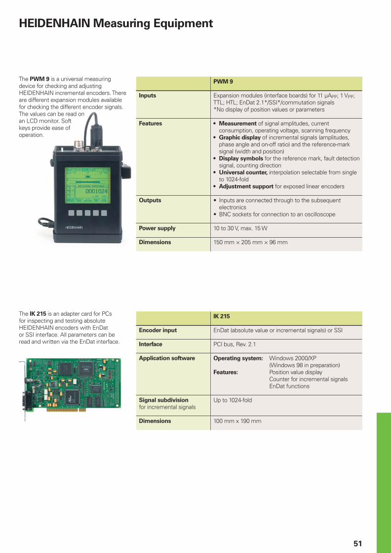
51
The PWM 9 is a universal measuring device for checking and adjusting HEIDENHAIN incremental encoders. There are different expansion modules available for checking the different encoder signals. The values can be read on an LCD monitor. Soft keys provide ease of operation.
PWM 9
Inputs Expansion modules (interface boards) for 11 µAPP; 1 VPP; TTL; HTL; EnDat 2.1*/SSI*/commutation signals*No display of position values or parameters
Features Measurement of signal amplitudes, current consumption, operating voltage, scanning frequencyGraphic display of incremental signals (amplitudes, phase angle and on-off ratio) and the reference-mark signal (width and position)Display symbols for the reference mark, fault detection signal, counting directionUniversal counter, interpolation selectable from single to 1024-foldAdjustment support for exposed linear encoders
•
•
•
•
•
Outputs Inputs are connected through to the subsequent electronicsBNC sockets for connection to an oscilloscope
•
•
Power supply 10 to 30 V, max. 15 W
Dimensions 150 mm × 205 mm × 96 mm
The IK 215 is an adapter card for PCs for inspecting and testing absolute HEIDENHAIN encoders with EnDat or SSI interface. All parameters can be read and written via the EnDat interface.
IK 215
Encoder input EnDat (absolute value or incremental signals) or SSI
Interface PCI bus, Rev. 2.1
Application software Operating system: Windows 2000/XP (Windows 98 in preparation)Features: Position value display Counter for incremental signals EnDat functions
Signal subdivision
for incremental signalsUp to 1024-fold
Dimensions 100 mm x 190 mm
HEIDENHAIN Measuring Equipment

KR HEIDENHAIN LTD. Suite 1415, Family Tower Building 958-2 Yeongtong-Dong Paldal-Gu, Suwon 442-470 Kyeonggi-Do, South Korea
{ (82) 312011511 e-mail: [email protected]
MX HEIDENHAIN CORPORATION MEXICO Av. Las Américas 1808 Fracc. Valle Dorado 20235, Aguascalientes, Ags., Mexico
{ (449) 9130870 e-mail: [email protected]
NL HEIDENHAIN NEDERLAND B.V. Copernicuslaan 34, 6716 BM EDE The Netherlands
{ (0318) 581800 e-mail: [email protected]
NO HEIDENHAIN NUF Boks 63 7301 Orkanger, Norway
{ (072) 480048 e-mail: [email protected]
PH MachineBank‘s Corporation Quezon City, Manila, Philippines { (2) 7113751
PT FARRESA ELECTRÓNICA LDA. 4470 Maia, Portugal
{ (22) 9478140 e-mail: [email protected]
RO − HU
RU GERTNER Service GmbH 125057 Moskau, Russia { (095) 931/9645 e-mail: [email protected]
SE HEIDENHAIN AB Storsätragränd 5 12739 Skärholmen, Sweden
{ (08) 53193350 e-mail: [email protected]
SG HEIDENHAIN PACIFIC PTE LTD. 51, Ubi Crescent Singapore 408593, Republic of Singapore
{ (65) 6749-3238 e-mail: [email protected]
SK − CZ
TH HEIDENHAIN (THAILAND) LTD 52/72 Moo5 Chaloem Phra Kiat Rama 9 Rd Nongbon, Pravate, Bangkok 10250, Thailand
{ (66) 2/398-4147 e-mail: [email protected]
TR T&M Mühendislik Mümessillik 34728 Erenköy/Istanbul, Turkey
{ (216) 3022345 e-mail: [email protected]
TW HEIDENHAIN Co., Ltd. No. 12-5, Gong 33rd Road Taichung Industrial Park Taichung 407, Taiwan, R.O.C.
{ (886-4) 23588977 e-mail: [email protected]
US HEIDENHAIN CORPORATION 333 State Parkway Schaumburg, IL 60173-5337, USA
{ (847) 490-1191 e-mail: [email protected]
ZA MAFEMA SALES SERVICES C.C. Midrand, 1685, South Africa
{ (11) 3144416 e-mail: [email protected]
CN HEIDENHAIN (Tianjin) Optics and Electronics Co. Ltd. Tian Wei San Jie, Area A, Beijing Tianzhu Airport Industrial Zone, Shunyi District 100022 Beijing, China { (86) 10-80420000 e-mail: [email protected]
CZ HEIDENHAIN s.r.o. Stremchová 16 106 00 Praha 10, Czech Republic
{ 272658131 e-mail: [email protected]
DK TP TEKNIK A/S Korskildelund 4 2670 Greve, Denmark
{ (70) 100966 e-mail: [email protected]
ES FARRESA ELECTRONICA S.A. Les Corts, 36-38 bajos 08028 Barcelona, Spain
{ 934092491 e-mail: [email protected]
FI HEIDENHAIN AB Mikkelänkallio 3 02770 Espoo, Finland
{ (09) 8676476 e-mail: [email protected]
FR HEIDENHAIN FRANCE sarl 2, Avenue de la Cristallerie 92316 Sèvres, France
{ 0141143000 e-mail: [email protected]
GB HEIDENHAIN (G.B.) Limited 200 London Road, Burgess Hill West Sussex RH15 9RD, Great Britain
{ (01444) 247711 e-mail: [email protected]
GR MB Milionis Vassilis 173 41 Athens, Greece
{ (0210) 9336607 e-mail: [email protected]
HK HEIDENHAIN LTD Unit 2, 15/F, Apec Plaza 49 Hoi Yuen Road Kwun Tong Kowloon, Hong Kong
{ (852) 27591920 e-mail: [email protected]
HU HEIDENHAIN Kereskedelmi Képviselet Hrivnák Pál utca 13. 1237 Budapest, Hungary
{ (1) 4210952 e-mail: [email protected]
IL NEUMO VARGUS Tel-Aviv 61570, Israel
{ (3) 5373275 e-mail: [email protected]
IN ASHOK & LAL Chennai – 600 030, India
{ (044) 26151289 e-mail: [email protected]
IT HEIDENHAIN ITALIANA S.r.l. Via Asiago 14 20128 Milano, Italy
{ 02270751 e-mail: [email protected]
JP HEIDENHAIN K.K. Kudan Center Bldg. 10th Floor Kudankita 4-1-7, Chiyoda-ku Tokyo 102-0073 Japan
{ (03) 3234-7781 e-mail: [email protected]
����������������� �������������� ��� ������������������������� ������� ���������������� ������������������ � � !�"� ��� ��
������� ������� �
AR NAKASE Asesoramiento Tecnico B1653AOX Villa Ballester, Argentina
{ (11) 47683643 e-mail: [email protected]
AT HEIDENHAIN Techn. Büro Österreich Dr.-Johannes-Heidenhain-Straße 5 83301 Traunreut, Germany
{ + 49 (8669) 311337 e-mail: [email protected]
AU FCR Motion Technology Pty. Ltd Laverton North 302, Australia
{ (3) 93626800 e-mail: [email protected]
BE HEIDENHAIN NV/SA Pamelse Klei 47, 1760 Roosdaal-Pamel, Belgium
{ (054) 343158 e-mail: [email protected]
BG ESD Bulgaria Ltd. 1172 Sofi a, Bulgaria
{ 29632949 e-mail: [email protected]
BR DIADUR Indústria e Comércio Ltda. Rua Servia, 329, Santo Amaro 04763-070 – São Paulo – SP, Brasil
{ (011) 5523 – 6777 e-mail: [email protected]
BY REAL 220047 Minsk, Belarus { (172) 383571 e-mail: [email protected]
CA HEIDENHAIN CORPORATION 11-335 Admiral Blvd., Unit 11 Mississauga, Ontario L5T2N2, Canada
{ (905) 670-8900 e-mail: [email protected]
CH HEIDENHAIN (SCHWEIZ) AG Post Box Vieristrasse 14 8603 Schwerzenbach, Switzerland
{ (044) 8062727 e-mail: [email protected]
DE HEIDENHAIN Technisches Büro Nord12681 Berlin, Deutschland
{ (030) 54705-240 e-mail: [email protected]
HEIDENHAIN Technisches Büro Mitte08468 Heinsdorfergrund, Deutschland
{ (03765) 69544 e-mail: [email protected]
HEIDENHAIN Technisches Büro West 58093 Hagen, Deutschland { (02331) 9579-0 e-mail: [email protected]
HEIDENHAIN Technisches Büro Südwest72131 Ofterdingen, Deutschland
{ (07473) 22733 e-mail: [email protected]
HEIDENHAIN Technisches Büro Südost83301 Traunreut, Deutschland
{ (08669) 311345 e-mail: [email protected]
Vollständige Adressen siehe www.heidenhain.deFor complete addresses see www.heidenhain.de
571 470-21 · 30 · 9/2005 · H · Printed in Germany · Subject to change without notice
Zu
m A
bh
eft
en
hie
r fa
lzen
! /
Fo
ld h
ere
fo
r fi
lin
g!