Embed Size (px)
Citation preview
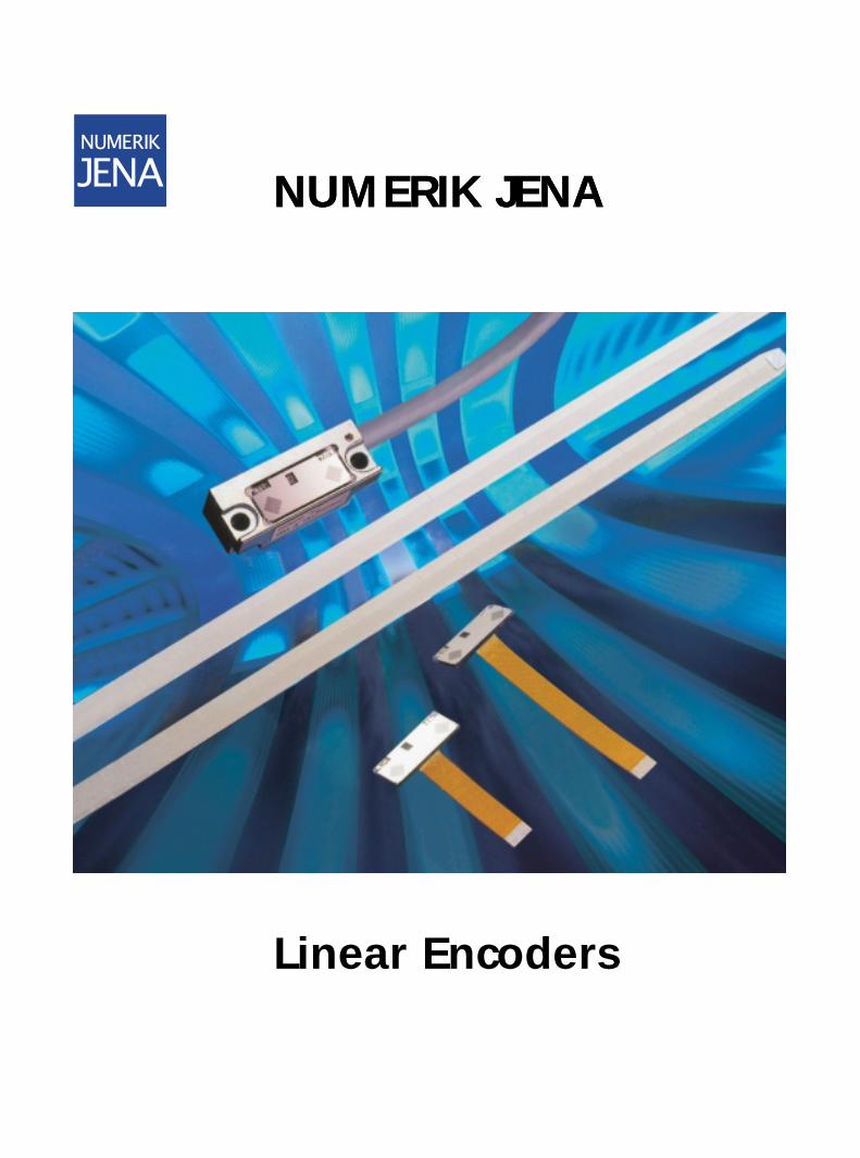
Linear Encoders
NUMERIK JENANUMERIK JENA

4
Seite
Exposed Linear Encoders 2Sealed Linear Encoders 3Encoder Kit L 4Model Overview 5
Functional Principle 7Optoelectronic ScanningMeasuring Standard 8SINGLEFLEX Scale TapeDOUBLEFLEX Scale TapeMechanical Design 9Exposed Linear EncodersSealed Linear EncodersLIE 5 - Mounting Tolerances 10General Mounting Information 11Protection Against Contamination 12
Thermal Behavior 13Exposed Linear EncodersSealed Linear EncodersResolution 14AccuracyReference Marks 15Possible Configuration 16
Power Supply 16Signal Interpolation 17Output Signals 18Cutoff FrequencyEdge SeparationMonitoring SignalSinusoidal Voltage SignalsSinusoidal Current Signals 19RS-422 Square-Wave SignalsElectromagnetic Compatibility 20
Connecting Elements and Cable 21CablesCouplingsFlange SocketsAccessories for Inspection and Adjustment 23FAV Guide Band Application DeviceSignal Adjustment KitSignal Monitor
Product Overview 24
Contents
1
2
Primary characteristics• Contact-free optical scanning of the scale
by the measuring head.• No mechanical effect on the slide system.• The customer’s slide system serves as guide
between the measuring head and scale.• High measuring velocity has no mechanical
limits. It is limited only by the cutoff frequency of the optoelectronic scanning or by the subsequent counter.
• High accuracy.• High resolution.• Large mounting tolerances with respect to
the attainable resolution.• Small space requirement.• Exact measurement in large temperature
ranges thanks to thermally defined behavior.• Scale and scanning head must be protected
against contamination from dust, swarf, oil, water etc.
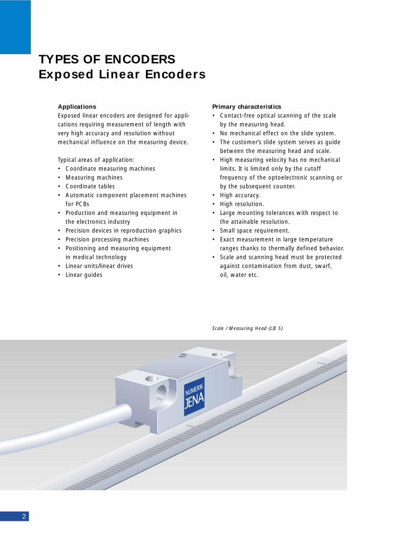
TYPES OF ENCODERSExposed Linear Encoders
Applications Exposed linear encoders are designed for appli-cations requiring measurement of length withvery high accuracy and resolution withoutmechanical influence on the measuring device.
Typical areas of application:• Coordinate measuring machines• Measuring machines• Coordinate tables• Automatic component placement machines
for PCBs• Production and measuring equipment in
the electronics industry• Precision devices in reproduction graphics• Precision processing machines• Positioning and measuring equipment
in medical technology• Linear units/linear drives• Linear guides
Scale / Measuring Head (LIE 5)
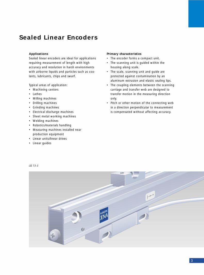
Sealed Linear Encoders
3
Primary characteristics• The encoder forms a compact unit.• The scanning unit is guided within the
housing along scale.• The scale, scanning unit and guide are
protected against contamination by an aluminum extrusion and elastic sealing lips.
• The coupling elements between the scanning carriage and transfer web are designed to transfer motion in the measuring direction only.
• Pitch or other motion of the connecting web in a direction perpendicular to measurement is compensated without affecting accuracy.
Applications Sealed linear encoders are ideal for applicationsrequiring measurement of length with highaccuracy and resolution in harsh environmentswith airborne liquids and particles such as coo-lants, lubricants, chips and swarf.
Typical areas of application:• Machining centers• Lathes• Milling machines• Drilling machines• Grinding machines• Electrical discharge machines• Sheet metal working machines• Welding machines• Robotics/materials handling• Measuring machines installed near
production equipment• Linear units/linear drives• Linear guides
LIS 73-3
4
Primary characteristics• The Encoder Kit L is a slimmed-down linear
encoder consisting of a measuring standard, measuring module, interface PCB, and connecting cable.
• Contact-free optical scanning of the scale by the measuring module.
• High accuracy.• High resolution.• Very little space required.• The components must be protected against
contamination from dust, swarf, oil, water etc.
• The electromagnetic compatibility of the functional groups must be realized through an appropriate housing.
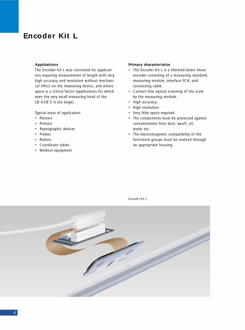
Applications The Encoder Kit L was conceived for applicati-ons requiring measurement of length with veryhigh accuracy and resolution without mechani-cal effect on the measuring device, and wherespace is a critical factor (applications for whicheven the very small measuring head of the LIE 4/LIE 5 is too large).
Typical areas of application:• Plotters• Printers• Reprographic devices• Probes• Robots• Coordinate tables• Medical equipment
Encoder Kit L
Encoder Kit L
5
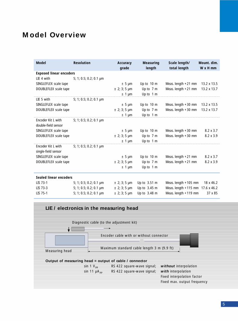
Model Resolution Accuracy Measuring Scale length/ Mount. dim.grade length total length W x H mm
Exposed linear encoders LIE 4 with 5; 1; 0.5; 0.2; 0.1 µm SINGLEFLEX scale tape ± 5 µm Up to 10 m Meas. length +21 mm 13.2 x 13.5DOUBLEFLEX scale tape ± 2; 3; 5 µm Up to 7 m Meas. length +21 mm 13.2 x 13.7
± 1 µm Up to 1 mLIE 5 with 5; 1; 0.5; 0.2; 0.1 µm SINGLEFLEX scale tape ± 5 µm Up to 10 m Meas. length +30 mm 13.2 x 13.5DOUBLEFLEX scale tape ± 2; 3; 5 µm Up to 7 m Meas. length +30 mm 13.2 x 13.7
± 1 µm Up to 1 mEncoder Kit L with 5; 1; 0.5; 0.2; 0.1 µm double-field sensorSINGLEFLEX scale tape ± 5 µm Up to 10 m Meas. length +30 mm 8.2 x 3.7DOUBLEFLEX scale tape ± 2; 3; 5 µm Up to 7 m Meas. length +30 mm 8.2 x 3.9
± 1 µm Up to 1 mEncoder Kit L with 5; 1; 0.5; 0.2; 0.1 µm single-field sensorSINGLEFLEX scale tape ± 5 µm Up to 10 m Meas. length +21 mm 8.2 x 3.7DOUBLEFLEX scale tape ± 2; 3; 5 µm Up to 7 m Meas. length +21 mm 8.2 x 3.9
± 1 µm Up to 1 m
Sealed linear encoders LIS 73-1 5; 1; 0.5; 0.2; 0.1 µm ± 2; 3; 5 µm Up to 3.51 m Meas. length +105 mm 18 x 46.2LIS 73-3 5; 1; 0.5; 0.2; 0.1 µm ± 2; 3; 5 µm Up to 3.45 m Meas. length +115 mm 17.6 x 46.2LIS 75-1 5; 1; 0.5; 0.2; 0.1 µm ± 2; 3; 5 µm Up to 3.48 m Meas. length +119 mm 37 x 85
Model Overview
LIE / electronics in the measuring head
Diagnostic cable (to the adjustment kit)
Measuring head
Encoder cable with or without connector
Maximum standard cable length 3 m (9.9 ft)
Output of measuring head = output of cable / connectorsin 1 VPP RS 422 square-wave signal; without interpolationsin 11 µAPP RS 422 square-wave signal; with interpolation
Fixed interpolation factorFixed max. output frequency
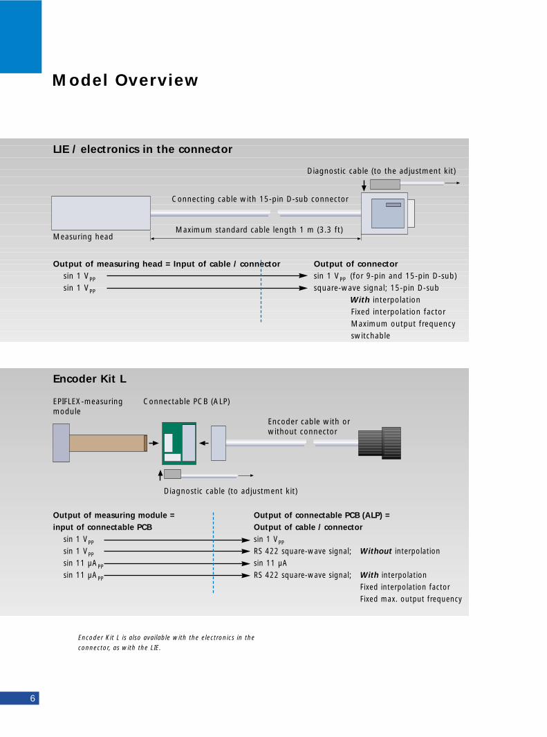
Encoder Kit L is also available with the electronics in the
connector, as with the LIE.
Model Overview
6
LIE / electronics in the connector
Diagnostic cable (to the adjustment kit)
Measuring head
Connecting cable with 15-pin D-sub connector
Maximum standard cable length 1 m (3.3 ft)
Output of measuring head = Input of cable / connector Output of connectorsin 1 VPP sin 1 VPP (for 9-pin and 15-pin D-sub)sin 1 VPP square-wave signal; 15-pin D-sub
With interpolation Fixed interpolation factorMaximum output frequencyswitchable
Encoder Kit L
Diagnostic cable (to adjustment kit)
EPIFLEX-measuringmodule
Connectable PCB (ALP)
Encoder cable with orwithout connector
Output of measuring module = Output of connectable PCB (ALP) =input of connectable PCB Output of cable / connector
sin 1 VPP sin 1 VPP
sin 1 VPP RS 422 square-wave signal; Without interpolationsin 11 µAPP sin 11 µAsin 11 µAPP RS 422 square-wave signal; With interpolation
Fixed interpolation factorFixed max. output frequency
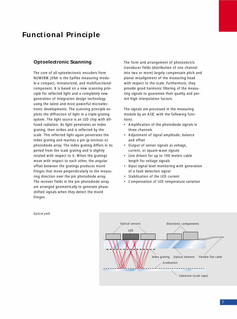
The form and arrangement of photoelectrictransducer fields (distribution of one channelinto two or more) largely compensate pitch andplanar misalignment of the measuring headwith respect to the scale. Furthermore, theyprovide good harmonic filtering of the measu-ring signals to guarantee their quality and per-mit high interpolation factors.
The signals are processed in the measuringmodule by an ASIC with the following func-tions:• Amplification of the photodiode signals in
three channels• Adjustment of signal amplitude, balance
and offset• Output of sensor signals as voltage,
current, or square-wave signals• Line drivers for up to 100 meters cable
length for voltage signals• Input signal level monitoring with generation
of a fault detection signal• Stabilization of the LED current• Compensation of LED temperature variation
Optoelectronic Scanning
The core of all optoelectronic encoders fromNUMERIK JENA is the Epiflex measuring modu-le-a compact, miniaturized, and multifunctionalcomponent. It is based on a new scanning prin-ciple for reflected light and a completely newgeneration of integration design technologyusing the latest and most powerful microelec-tronic developments. The scanning principle ex-ploits the diffraction of light in a triple-gratingsystem. The light source is an LED chip with dif-fused radiation. Its light penetrates an indexgrating, then strikes and is reflected by thescale. This reflected light again penetrates theindex grating and reaches a pin (p-intrinsic-n)photodiode array. The index grating differs in itsperiod from the scale grating and is slightlyrotated with respect to it. When the gratingsmove with respect to each other, the angularoffset between the gratings produces moiréfringes that move perpendicularly to the measu-ring direction over the pin photodiode array.The receiver fields in the pin photodiode arrayare arranged geometrically to generate phase-shifted signals when they detect the moiré fringes.
Functional Principle
Optical path
7
Optical sensors
LED
Electronic components
Index grating
Graduation
Substrate (scale tape)
Optical element Flexible flat cable
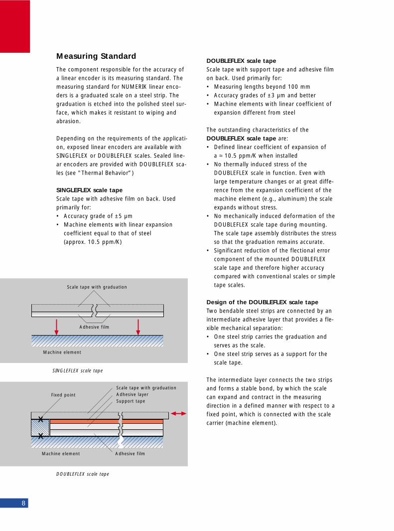
DOUBLEFLEX scale tapeScale tape with support tape and adhesive filmon back. Used primarily for:• Measuring lengths beyond 100 mm • Accuracy grades of ±3 µm and better• Machine elements with linear coefficient of
expansion different from steel
The outstanding characteristics of the DOUBLEFLEX scale tape are: • Defined linear coefficient of expansion of
a ≈ 10.5 ppm/K when installed • No thermally induced stress of the
DOUBLEFLEX scale in function. Even with large temperature changes or at great diffe-rence from the expansion coefficient of the machine element (e.g., aluminum) the scale expands without stress.
• No mechanically induced deformation of the DOUBLEFLEX scale tape during mounting. The scale tape assembly distributes the stress so that the graduation remains accurate.
• Significant reduction of the flectional error component of the mounted DOUBLEFLEX scale tape and therefore higher accuracy compared with conventional scales or simple tape scales.
Design of the DOUBLEFLEX scale tapeTwo bendable steel strips are connected by anintermediate adhesive layer that provides a fle-xible mechanical separation:• One steel strip carries the graduation and
serves as the scale.• One steel strip serves as a support for the
scale tape.
The intermediate layer connects the two stripsand forms a stable bond, by which the scalecan expand and contract in the measuringdirection in a defined manner with respect to afixed point, which is connected with the scalecarrier (machine element).
DOUBLEFLEX scale tape
8
Measuring Standard
The component responsible for the accuracy ofa linear encoder is its measuring standard. Themeasuring standard for NUMERIK linear enco-ders is a graduated scale on a steel strip. Thegraduation is etched into the polished steel sur-face, which makes it resistant to wiping andabrasion.
Depending on the requirements of the applicati-on, exposed linear encoders are available withSINGLEFLEX or DOUBLEFLEX scales. Sealed line-ar encoders are provided with DOUBLEFLEX sca-les (see "Thermal Behavior”)
SINGLEFLEX scale tapeScale tape with adhesive film on back. Used primarily for:• Accuracy grade of ±5 µm• Machine elements with linear expansion
coefficient equal to that of steel (approx. 10.5 ppm/K)
SINGLEFLEX scale tape
X
X
Scale tape with graduation
Adhesive film
Scale tape with graduationAdhesive layerSupport tape
Adhesive filmMachine element
Machine element
Fixed point
Sealed Linear Encoders
In sealed linear encoders, the scale tape andscanning system are protected in an aluminumhousing against dust, chips, oil and water.
The scanning head is guided along the scale byan internal, low-friction ball bearing, so thatrelatively generous mounting tolerances arepossible.
The scale tape and the scanning carriage withthe scanning system are completely separatedfrom each other.
Between the measuring carriage and theconnecting web, a special coupling that is verystiff in the measuring direction compensatesother motion between the connecting web andscale without reducing measuring accuracy.
Exposed Linear Encoders
Exposed linear encoders consist of a measuringhead and a scale. The two are connected overthe guideway of the slide system. The scaletape is fastened by a self-adhesive tape on itsback.
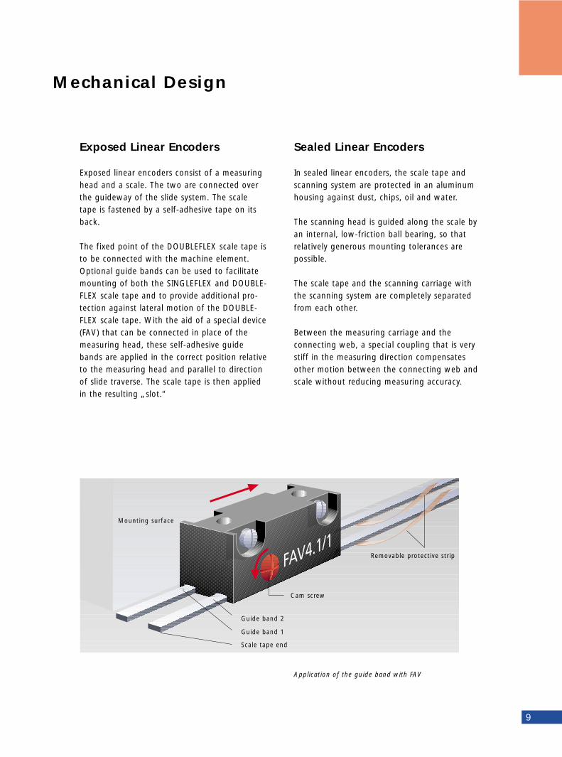
The fixed point of the DOUBLEFLEX scale tape isto be connected with the machine element.Optional guide bands can be used to facilitatemounting of both the SINGLEFLEX and DOUBLE-FLEX scale tape and to provide additional pro-tection against lateral motion of the DOUBLE-FLEX scale tape. With the aid of a special device(FAV) that can be connected in place of themeasuring head, these self-adhesive guidebands are applied in the correct position relativeto the measuring head and parallel to directionof slide traverse. The scale tape is then appliedin the resulting „slot.“
Mechanical Design
Application of the guide band with FAV
9
Mounting surface
Cam screw
Removable protective strip
Guide band 2
Guide band 1
Scale tape end
10
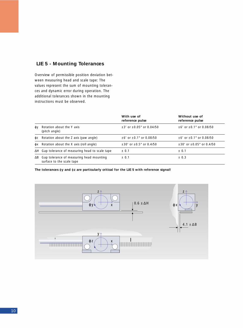
LIE 5 - Mounting Tolerances
Overview of permissible position deviation bet-ween measuring head and scale tape: Thevalues represent the sum of mounting toleran-ces and dynamic error during operation. Theadditional tolerances shown in the mountinginstructions must be observed.
With use of Without use of reference pulse reference pulse
ϕy Rotation about the Y axis ±3’ or ±0.05° or 0.04/50 ±6’ or ±0.1° or 0.08/50(pitch angle)
ϕz Rotation about the Z axis (yaw angle) ±6’ or ±0.1° or 0.08/50 ±6’ or ±0.1° or 0.08/50
ϕx Rotation about the X axis (roll angle) ±30’ or ±0.5° or 0.4/50 ±30’ or ±0.05° or 0.4/50
∆H Gap tolerance of measuring head to scale tape ± 0.1 ± 0.1
∆B Gap tolerance of measuring head mounting ± 0.1 ± 0.3surface to the scale tape
The tolerances ϕy and ϕz are particularly critical for the LIE 5 with reference signal!
ϕ y
z
x
ϕ z
y
x
ϕ x
z
y0.6 ± ∆H
4.1 ±∆B
The measuring or positioning error of a machi-ne are influenced essentially by the dynamicaccuracy of the table slide system. To minimizethe Abbe comparator error resulting from thissystem, the encoder should be mounted as clo-sely as possible to the measuring or workingplane or in close proximity to the guideway. Ifthe machine has dual guideways, the best posi-tion for the encoder is between them.
The gap between measuring head and scaletape in exposed linear encoders is adjusted withthe aid of a provided feeler gauge. For sealedlinear encoders, the shipping brace serves to setthe gap between the housing and the connec-ting web.
General MountingInformation
11
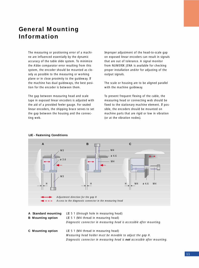
A Standard mounting LIE 5 1 (through hole in measuring head)B Mounting option LIE 5 1 (M4 thread in measuring head)
Diagnostic connector in measuring head is accessible after mounting.
C Mounting option LIE 5 1 (M4 thread in measuring head)Measuring head holder must be movable to adjust the gap H.Diagnostic connector in measuring head is not accessible after mounting.
A B C
Improper adjustment of the head-to-scale gapon exposed linear encoders can result in signalsthat are out of tolerance. A signal monitorfrom NUMERIK JENA is available for checkingproper installation and/or for adjusting of theoutput signals.
The scale or housing are to be aligned parallelwith the machine guideway.
To prevent frequent flexing of the cable, themeasuring head or connecting web should befixed to the stationary machine element. If pos-sible, the encoders should be mounted onmachine parts that are rigid or low in vibration(or at the vibration nodes).
LIE - Fastening Conditions
Adjustment direction for the gap H
Access to the diagnostic connector in the measuring head
M3
M3
H H H
M4
M4 M4
M4ø 3.6
ø 4.6
ø 4.6
Protection against Contamination
12
Exposed encoders have no integral protectionagainst contamination. The selected scanningprinciple (double-field sensor, two or more pho-toreceivers per channel) provides high redun-dancy, so that small amounts of contaminationhave no influence on measuring accuracy.
If the encoder is exposed to heavy contaminati-on, appropriate protective measures must betaken, or the encoder must be mounted whereit can be easily accessed for cleaning. Frequentcleaning, even with solvents, will not damagethe scale tape.
Sealed encoders are designed to protect thescale against dust and splashwater in accordan-ce with IEC 529 or EN 60 529.
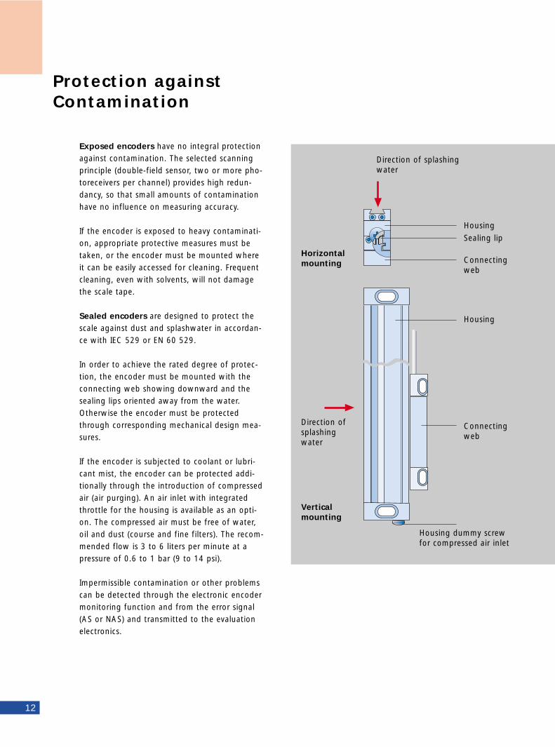
In order to achieve the rated degree of protec-tion, the encoder must be mounted with theconnecting web showing downward and thesealing lips oriented away from the water.Otherwise the encoder must be protectedthrough corresponding mechanical design mea-sures.
If the encoder is subjected to coolant or lubri-cant mist, the encoder can be protected addi-tionally through the introduction of compressedair (air purging). An air inlet with integratedthrottle for the housing is available as an opti-on. The compressed air must be free of water,oil and dust (course and fine filters). The recom-mended flow is 3 to 6 liters per minute at apressure of 0.6 to 1 bar (9 to 14 psi).
Impermissible contamination or other problemscan be detected through the electronic encodermonitoring function and from the error signal(AS or NAS) and transmitted to the evaluationelectronics.
Direction of splashingwater
Direction ofsplashingwater
Horizontalmounting
Verticalmounting
Housing
Sealing lip
Housing
Connecting web
Housing dummy screwfor compressed air inlet
Connecting web
rature deviates from 20° C (68 °F) there will beno resulting measuring or machining error.If the coefficient of expansion of the measuredobject (e.g., a workpiece) is other than a ≈ 10.5ppm/K, and/or if the temperature of the scaletape differs from that of the measured object,then the difference can be exactly compensatednumerically, provided that the temperatures ofthe scale tape and measured object are known.
Exposed Linear EncodersWherever DOUBLEFLEX scale tape is used, themeasuring standard behaves like steel with alinear expansion coefficient of α ≈ 10.5 ppm/K,regardless of the temperature and expansioncoefficient of the machine element to which itis connected. The thermal reference point lies atthe beginning of the measuring length (fixedpoint).
Benefit:If the scale tape and a steel workpiece have thesame temperature, then even when the tempe-
Thermal Behavior
13
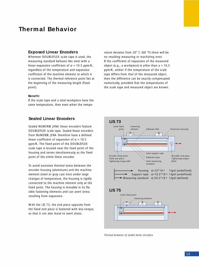
Sealed Linear Encoders
Sealed NUMERIK JENA linear encoders featureDOUBLEFLEX scale tape. Sealed linear encodersfrom NUMERIK JENA therefore have a definedlinear coefficient of expansion of α ≈ 10.5ppm/K. The fixed point of the DOUBLEFLEXscale tape is located near the fixed point of thehousing and serves simultaneously as the fixedpoint of the entire linear encoder.
To avoid excessive thermal stress between theencoder housing (aluminum) and the machineelement (steel or gray cast iron) under largechanges of temperature, the housing is rigidlyconnected to the machine element only at thefixed point. The housing is movable in its fle-xible fastening elements and can avert stressresulting from expansion.
With the LIS 73, the end piece opposite fromthe fixed end piece is fastened with less torque,so that it can also move to avert stress.
Thermal behavior of sealed linear encoders
Scale fixedpoint
Encoder fixed pointFixed end pieceTightening torque Md
Housing α<25*10-6 1/grd (undefined)Support tape α>10.5*10-6 1/grd (undefined)
Measuring standard α∼ 10.5*10-6 1/grd (defined)
Movable end pieceTightening torque Md/2
Fastening element
Scale fixed point
Fastening element
Adhesive film
Steel support tape
Adhesive layer
Steel measuringstandard
Aluminum housing
LIS 75
LIS 73
• Scale accuracy• Influences of photoelectrical scanning
and signal processing• Influences of the guide between the
measuring head and scale, and of the mounting tolerances
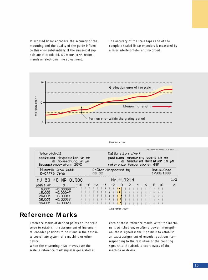
The last two influencing variables affect theposition error within one signal period. Thiserror is random in character and is superimpo-sed as an envelope curve on the scale error.
If the encoder is optimally mounted, the positi-on error within one signal period is ± 1 to 2%of the grating period.
The accuracy of linear encoders is expressed interms of accuracy grades. The extreme values oferror with reference to their mean value lie wit-hin ± a µm for a position within any maximumone-meter section of the measuring length.
For measuring lengths below one meter, thetolerance (± a) refers to the respective measu-ring length. The accuracy values apply for areference temperature of 20 °C (68 °F).
For exposed linear encoders, the above definiti-on of accuracy applies only to the scale. In thiscase, it is referred to as the scale accuracy. Thesystem accuracy is determined by the followingfactors:
Accuracy
Resolution
14
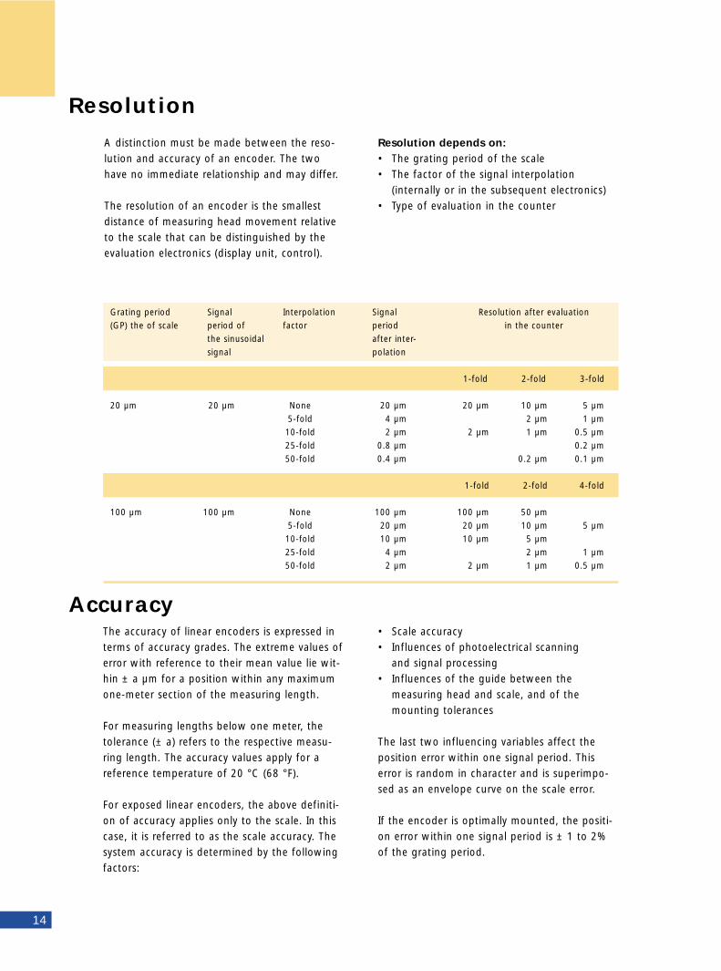
Resolution depends on:• The grating period of the scale• The factor of the signal interpolation
(internally or in the subsequent electronics)• Type of evaluation in the counter
Grating period Signal Interpolation Signal Resolution after evaluation
(GP) the of scale period of factor period in the counter
the sinusoidal after inter-
signal polation
1-fold 2-fold 3-fold
20 µm 20 µm None 20 µm 20 µm 10 µm 5 µm
5-fold 4 µm 2 µm 1 µm
10-fold 2 µm 2 µm 1 µm 0.5 µm
25-fold 0.8 µm 0.2 µm
50-fold 0.4 µm 0.2 µm 0.1 µm
1-fold 2-fold 4-fold
100 µm 100 µm None 100 µm 100 µm 50 µm
5-fold 20 µm 20 µm 10 µm 5 µm
10-fold 10 µm 10 µm 5 µm
25-fold 4 µm 2 µm 1 µm
50-fold 2 µm 2 µm 1 µm 0.5 µm
A distinction must be made between the reso-lution and accuracy of an encoder. The twohave no immediate relationship and may differ.
The resolution of an encoder is the smallestdistance of measuring head movement relativeto the scale that can be distinguished by theevaluation electronics (display unit, control).
Reference MarksCalibration chart
15
+a
-a
0
Posi
tio
n e
rro
r
Position error within the grating period
Measuring length
Graduation error of the scale
Position error
Reference marks at defined points on the scaleserve to establish the assignment of incremen-tal encoder positions to positions in the absolu-te coordinate system of a machine or otherdevice.When the measuring head moves over thescale, a reference mark signal is generated at
each of these reference marks. After the machi-ne is switched on, or after a power interrupti-on, these signals make it possible to establishan exact assignment of encoder positions (cor-responding to the resolution of the countingsignals) to the absolute coordinates of themachine or device.
In exposed linear encoders, the accuracy of themounting and the quality of the guide influen-ce this error substantially. If the sinusoidal sig-nals are interpolated, NUMERIK JENA recom-mends an electronic fine adjustment.
The accuracy of the scale tapes and of thecomplete sealed linear encoders is measured bya laser interferometer and recorded.
Power Supply
16
Possible configuration • Reference marks spaced 50 mm apart; the
user can activate one or more of them, e.g., through additional switches
• Reference marks at midpoint of measuring length
• Reference mark position as requested by customer
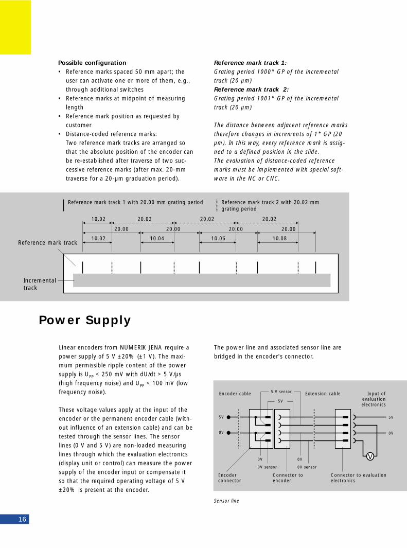
• Distance-coded reference marks:Two reference mark tracks are arranged so that the absolute position of the encoder canbe re-established after traverse of two suc-cessive reference marks (after max. 20-mm traverse for a 20-µm graduation period).
Reference mark track 1:Grating period 1000* GP of the incrementaltrack (20 µm)Reference mark track 2: Grating period 1001* GP of the incrementaltrack (20 µm)
The distance between adjacent reference markstherefore changes in increments of 1* GP (20µm). In this way, every reference mark is assig-ned to a defined position in the slide.The evaluation of distance-coded referencemarks must be implemented with special soft-ware in the NC or CNC.
Reference mark track 1 with 20.00 mm grating period Reference mark track 2 with 20.02 mm grating period
Reference mark track
Incremental track
Linear encoders from NUMERIK JENA require apower supply of 5 V ±20% (±1 V). The maxi-mum permissible ripple content of the powersupply is UPP < 250 mV with dU/dt > 5 V/µs(high frequency noise) and UPP < 100 mV (lowfrequency noise).
These voltage values apply at the input of theencoder or the permanent encoder cable (with-out influence of an extension cable) and can betested through the sensor lines. The sensorlines (0 V and 5 V) are non-loaded measuringlines through which the evaluation electronics(display unit or control) can measure the powersupply of the encoder input or compensate itso that the required operating voltage of 5 V±20% is present at the encoder.
Encoderconnector
Connector toencoder
Connector to evaluationelectronics
Extension cableEncoder cable 5 V sensor
5V
5V 5V
0V0V
0V
0V sensor 0V sensor
0V
Input ofevaluationelectronics
The power line and associated sensor line arebridged in the encoder's connector.
Sensor line
10.02
20.00 20.00 20.00 20.00
10.02 10.04 10.06 10.08
20.02 20.02 20.02
Example:
Max. signal input 2.0 MHz (8 MHz counting
frequency of the CNC: frequency with 4-fold
evaluation)
Desired inter- 10 (resolution 0.5 µm with
polation factor: 20 µm grating period)
Max. selectable 4 (signal frequency limited
frequency index: to 2 MHz; ≤ max. signal input
frequency of the CNC)
Resulting max. 80 m/min (3150 ipm)
traversing speed:
00 50 100 150
1
2y3
z
4
Internal signal interpolation up to a factor of 50is available as an option with all NUMERIK JENAencoders. The interpolation electronics can beintegrated in the
measuring head (LIE, LIS) or on the printed circuit board (Encoder Kit) or in the sub-D connector (all encoders).
In an internal resistor network and bridge cir-cuit, n (= interpolation factor) signals are gene-rated within one primary signal period. Theinterpolated signals are phase-shifted by 2Π/n.At the zero crossovers of these signals, aclocked trigger generates square-wave signals.
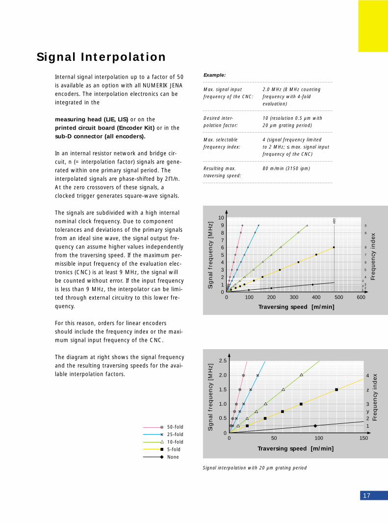
The signals are subdivided with a high internalnominal clock frequency. Due to componenttolerances and deviations of the primary signalsfrom an ideal sine wave, the signal output fre-quency can assume higher values independentlyfrom the traversing speed. If the maximum per-missible input frequency of the evaluation elec-tronics (CNC) is at least 9 MHz, the signal willbe counted without error. If the input frequencyis less than 9 MHz, the interpolator can be limi-ted through external circuitry to this lower fre-quency.
For this reason, orders for linear encodersshould include the frequency index or the maxi-mum signal input frequency of the CNC.
The diagram at right shows the signal frequencyand the resulting traversing speeds for the avai-lable interpolation factors.
Signal Interpolation
17
10
8
6
4
2
00 200 400 600100 300 500
9
7
5
3
1
480
1 2y 3z
4
5
6
7
8
9
0
Traversing speed [m/min]
Sig
nal
fre
qu
ency
[M
Hz]
Signal interpolation with 20 µm grating period
Traversing speed [m/min]
Sig
nal
fre
qu
ency
[M
Hz]
Freq
uen
cy i
nd
exFr
equ
ency
in
dex
50-fold
25-fold
10-fold
5-fold
None
2.5
2.0
1.5
1.0
0.5
Output signals
18
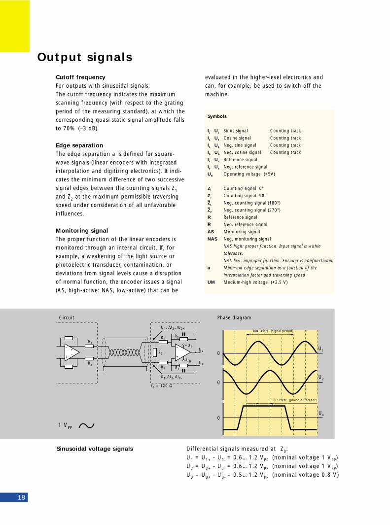
Cutoff frequencyFor outputs with sinusoidal signals:The cutoff frequency indicates the maximumscanning frequency (with respect to the gratingperiod of the measuring standard), at which thecorresponding quasi static signal amplitude fallsto 70% (–3 dB).
Edge separationThe edge separation a is defined for square-wave signals (linear encoders with integratedinterpolation and digitizing electronics). It indi-cates the minimum difference of two successivesignal edges between the counting signals Z1
and Z2 at the maximum permissible traversingspeed under consideration of all unfavorableinfluences.
Monitoring signalThe proper function of the linear encoders ismonitored through an internal circuit. If, forexample, a weakening of the light source orphotoelectric transducer, contamination, ordeviations from signal levels cause a disruptionof normal function, the encoder issues a signal(AS, high-active: NAS, low-active) that can be
U0
U2
U10
0
0
Ra
Ra
Z0
R1
R1
Z0 = 120 Ω
R2
R2
-UB
+UB
U0
Ua−
+
−
+−+
U1+/U2+ /U0+
U1- /U2- /U0-
Circuit Phase diagram
360° elect. (signal period)
90° elect. (phase difference)
Differential signals measured at Z0:
U1 = U1+ - U1- = 0.6…1.2 VPP (nominal voltage 1 VPP)
U2 = U2+ - U2- = 0.6…1.2 VPP (nominal voltage 1 VPP)
U0 = U0+ - U0- = 0.5…1.2 VPP (nominal voltage 0.8 V)
1 VPP
Sinusoidal voltage signals
Symbols
I1 U1 Sinus signal Counting track
I2 U2 Cosine signal Counting track
I1- U1- Neg. sine signal Counting track
I2- U2- Neg. cosine signal Counting track
I0 U0 Reference signal
I0- U0- Neg. reference signal
UB Operating voltage (+5V)
Z1 Counting signal 0°
Z2 Counting signal 90°–Z1 Neg. counting signal (180°)–Z2 Neg. counting signal (270°)
R Reference signal –R Neg. reference signal
AS Monitoring signal
NAS Neg. monitoring signal
NAS high: proper function. Input signal is within
tolerance.
NAS low: improper function. Encoder is nonfunctional.
a Minimum edge separation as a function of the
interpolation factor and traversing speed
UM Medium-high voltage (+2.5 V)
evaluated in the higher-level electronics andcan, for example, be used to switch off themachine.
Ι 0
Ι 2
Ι 1Um
Um
Um
Ι1+−
+
−
+−+
Ι1-
∼ 80 kΩ
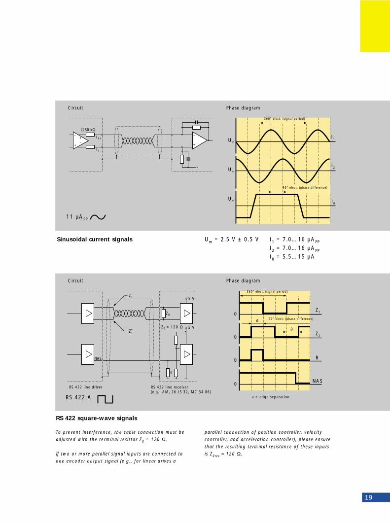
19
360° elect. (signal period)
Circuit Phase diagram
90° elect. (phase difference)
Sinusoidal current signals Um = 2.5 V ± 0.5 V Ι1 = 7.0…16 µAPP
Ι2 = 7.0…16 µAPP
Ι0 = 5.5…15 µA
11 µAPP
Z0
R
Z0 = 120 Ω
NAS
5 V
5 V
Z2
Z10
0
R0
NAS0
Z1
Z1a
a
Circuit Phase diagram
RS 422 square-wave signals
To prevent interference, the cable connection must be
adjusted with the terminal resistor Z0 = 120 Ω.
If two or more parallel signal inputs are connected to
one encoder output signal (e.g., for linear drives a
RS 422 A
RS 422 line driver RS 422 line receiver (e.g. AM, 26 LS 32, MC 34 86)
a = edge separation
360° elect. (signal period)
90° elect. (phase difference)
parallel connection of position controller, velocity
controller, and acceleration controller), please ensure
that the resulting terminal resistance of these inputs
is Z0res ≈ 120 Ω.
Electromagnetic Compatibility
20
Strong electromagnetic fields can result in spu-rious pulses in the measuring signals and causecounting errors. Possible sources of noise include:• Strong magnetic fields from transformers or
electric motors (particularly linear motors)• Contactors, relays, solenoid valves• High-frequency equipment, pulse generators,
switch-mode power supplies, and frequency inverters
• Power supply units and power lines to the above devices
To ensure maximum protection against noisefields: • Use only original NUMERIK JENA cable and
connecting elements.• Comply with the NUMERIK JENA shielding
recommendations.• Ensure that the encoder and evaluation elec-
tronics have the same electrical potential. They must be connected with the main signal ground through the machine chassis or through a separate potential compensating line (minimum cross section 6 mm2 Cu).
• Connect the encoder with the machine such that electrically conductive contact is ensured (paint-free mounting surface, electrically con-ductive screw and hole threads).
• Maintain a minimum spacing of 100 mm between signal cables and sources of interference.
• Maintain a minimum spacing of 200 mm between signal cable and inductors (switching power supply).
• Connect the encoders only to devices whose power supplies comply with EN 50 178 (protective low voltage)
• Configure the signal lines for minimum length and use no unshielded connections.
• If signal lines are routed together with spurious signal transmitting cables, use a grounded partition to ensure sufficient decoupling.
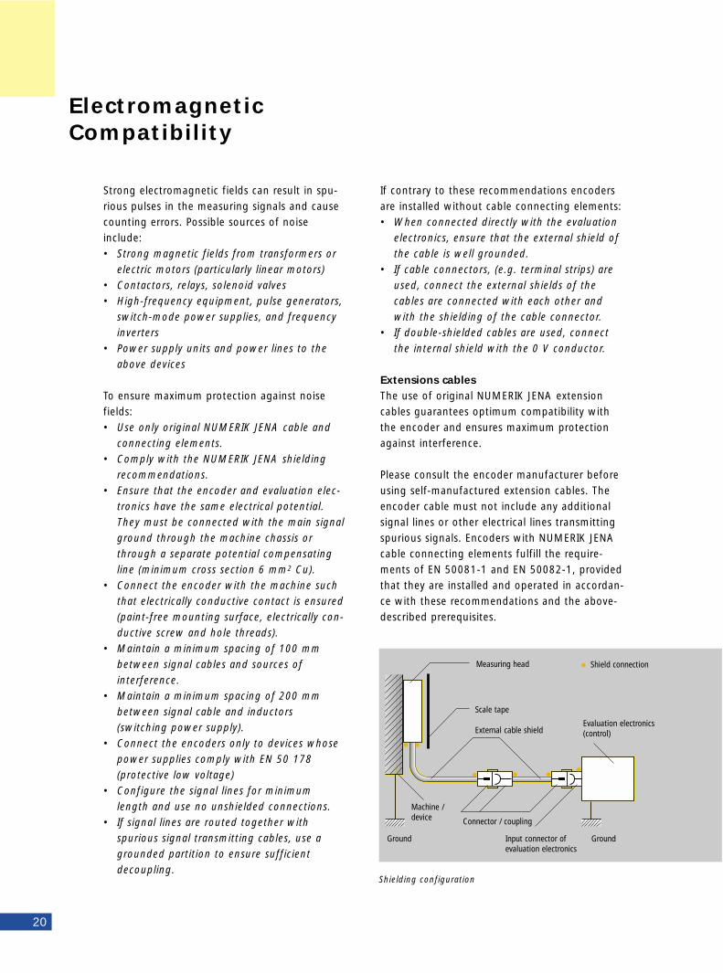
Shielding configuration
If contrary to these recommendations encodersare installed without cable connecting elements:• When connected directly with the evaluation
electronics, ensure that the external shield of the cable is well grounded.
• If cable connectors, (e.g. terminal strips) are used, connect the external shields of the cables are connected with each other and with the shielding of the cable connector.
• If double-shielded cables are used, connect the internal shield with the 0 V conductor.
Extensions cablesThe use of original NUMERIK JENA extensioncables guarantees optimum compatibility withthe encoder and ensures maximum protectionagainst interference.
Please consult the encoder manufacturer beforeusing self-manufactured extension cables. Theencoder cable must not include any additionalsignal lines or other electrical lines transmittingspurious signals. Encoders with NUMERIK JENAcable connecting elements fulfill the require-ments of EN 50081-1 and EN 50082-1, providedthat they are installed and operated in accordan-ce with these recommendations and the above-described prerequisites.
Measuring head
Ground Ground
Scale tape
Machine /device
External cable shieldEvaluation electronics(control)
Shield connection
Connector / coupling
Input connector of evaluation electronics
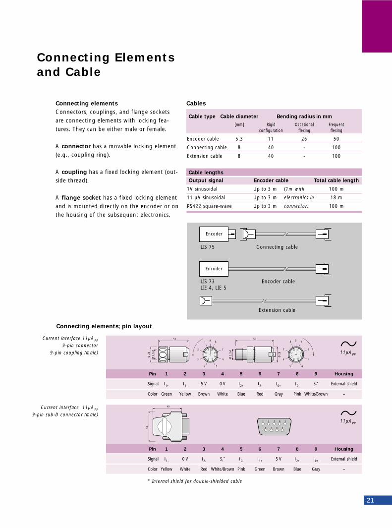
Connecting elementsConnectors, couplings, and flange socketsare connecting elements with locking fea-tures. They can be either male or female.
A connector has a movable locking element(e.g., coupling ring).
A coupling has a fixed locking element (out-side thread).
A flange socket has a fixed locking elementand is mounted directly on the encoder or onthe housing of the subsequent electronics.
Connecting Elements and Cable
21
Cables
Encoder
Encoder
LIS 75 Connecting cable
LIS 73 Encoder cableLIE 4, LIE 5
Extension cable
Cable type Cable diameter Bending radius in mm
[mm] Rigid Occasional Frequentconfiguration flexing flexing
Encoder cable 5.3 11 26 50
Connecting cable 8 40 - 100
Extension cable 8 40 - 100
Cable lengths
Output signal Encoder cable Total cable length
1V sinusoidal Up to 3 m (1m with 100 m
11 µA sinusoidal Up to 3 m electronics in 18 m
RS422 square-wave Up to 3 m connector) 100 m
91
2
3
4 5
8
7
6M 2
,3x1
53
Ø 2
8
98
7
6
5 4
1
2
3M 2
,3x1
56
Ø 2
8
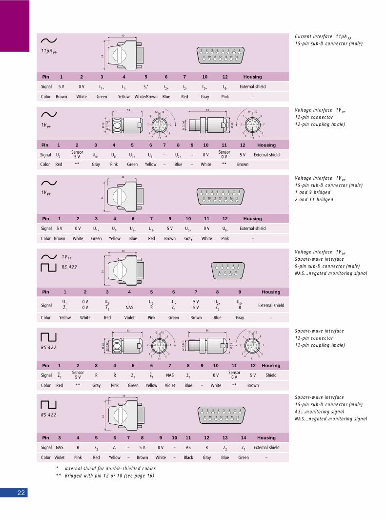
Current interface 11µAPP
9-pin connector
9-pin coupling (male)
Pin 1 2 3 4 5 6 7 8 9 Housing
Signal Ι1+ Ι1- 5 V 0 V Ι2+ Ι2- Ι0+ Ι0- SC* External shield
Color Green Yellow Brown White Blue Red Gray Pink White/Brown –
40
34
1 2 3 4 5
6 7 8 9
Current interface 11µAPP
9-pin sub-D connector (male)
Pin 1 2 3 4 5 6 7 8 9 Housing
Signal Ι1- 0 V Ι2- SC* Ι0- Ι1+ 5 V Ι2+ Ι0+ External shield
Color Yellow White Red White/Brown Pink Green Brown Blue Gray –
11µAPP
11µAPP
Connecting elements; pin layout
* Internal shield for double-shielded cable
40
34
4 5 6 7 8
12 13 14 15
3
11
2
10
1
9
Pin 1 2 3 4 5 6 7 10 12 Housing
Signal 5 V 0 V Ι1+ Ι1- SC* Ι2+ Ι2- Ι0+ Ι0- External shield
Color Brown White Green Yellow White/Brown Blue Red Gray Pink –
Current interface 11µAPP
15-pin sub-D connector (male)
22
40
34
4 5 6 7 8
12 13 14 15
3
11
2
10
1
9
Pin 1 2 3 4 6 7 9 10 11 12 Housing
Signal 5 V 0 V U1+ U1- U2+ U2- 5 V U0+ 0 V U0- External shield
Color Brown White Green Yellow Blue Red Brown Gray White Pink –
40
34
1 2 3 4 5
6 7 8 9
Pin 1 2 3 4 5 6 7 8 9 Housing
SignalU1- 0 V U2- – U0- U1+ 5 V U2+ U0+ External shieldZ1 0 V Z2 NAS R Z1 5 V Z2 R
Color Yellow White Red Violet Pink Green Brown Blue Gray –
98
7
654
1
2
3
12
11
10
M 2
,3x1
53
Ø 2
8
M 2
,3x1
56
Ø 2
8
91
2
345
8
7
6
10
11
12
Pin 1 2 3 4 5 6 7 8 9 10 11 12 Housing
Signal Z2Sensor
R R Z1 Z1 NAS Z2 0 VSensor
5 V Shield5 V 0 V
Color Red ** Gray Pink Green Yellow Violet Blue – White ** Brown
40
34
4 5 6 7 8
12 13 14 15
3
11
2
10
1
9
Pin 3 4 5 6 7 8 9 10 11 12 13 14 Housing
Signal NAS R Z2 Z1 – 5 V 0 V – AS R Z2 Z1 External shield
Color Violet Pink Red Yellow – Brown White – Black Gray Blue Green –
98
7
654
1
2
3
12
11
10
M 2
,3x1
53
Ø 2
8
M 2
,3x1
56
Ø 2
8
91
2
345
8
7
6
10
11
12
Pin 1 2 3 4 5 6 7 8 9 10 11 12 Housing
Signal U2-Sensor
U0+ U0- U1+ U1- − U2+ – 0 VSensor
5 V External shield5 V 0 V
Color Red ** Gray Pink Green Yellow – Blue – White ** Brown
Voltage interface 1VPP
15-pin sub-D connector (male)
1 and 9 bridged
2 and 11 bridged
Voltage interface 1VPP
Square-wave interface
9-pin sub-D connector (male)
NAS...negated monitoring signal
Square-wave interface
12-pin connector
12-pin coupling (male)
Square-wave interface
15-pin sub-D connector (male)
AS...monitoring signal
NAS...negated monitoring signal
Voltage interface 1VPP
12-pin connector
12-pin coupling (male)
11µAPP
1VPP
1VPP
1VPP
RS 422
RS 422
RS 422
* Internal shield for double-shielded cables
** Bridged with pin 12 or 10 (see page 16)
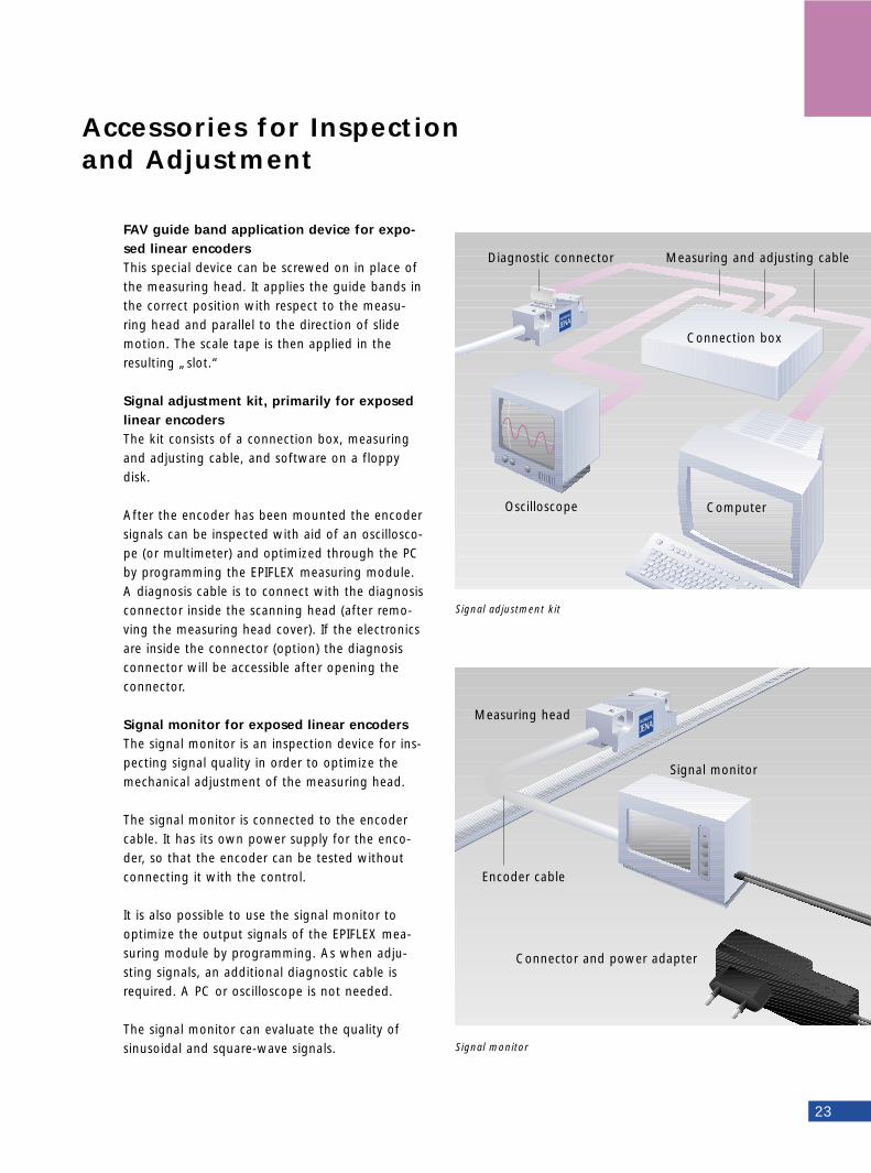
FAV guide band application device for expo-sed linear encodersThis special device can be screwed on in place ofthe measuring head. It applies the guide bands inthe correct position with respect to the measu-ring head and parallel to the direction of slidemotion. The scale tape is then applied in theresulting „slot.“
Signal adjustment kit, primarily for exposedlinear encodersThe kit consists of a connection box, measuringand adjusting cable, and software on a floppydisk.
After the encoder has been mounted the encodersignals can be inspected with aid of an oscillosco-pe (or multimeter) and optimized through the PCby programming the EPIFLEX measuring module.A diagnosis cable is to connect with the diagnosisconnector inside the scanning head (after remo-ving the measuring head cover). If the electronicsare inside the connector (option) the diagnosisconnector will be accessible after opening theconnector.
Signal monitor for exposed linear encoders The signal monitor is an inspection device for ins-pecting signal quality in order to optimize themechanical adjustment of the measuring head.
The signal monitor is connected to the encodercable. It has its own power supply for the enco-der, so that the encoder can be tested withoutconnecting it with the control.
It is also possible to use the signal monitor tooptimize the output signals of the EPIFLEX mea-suring module by programming. As when adju-sting signals, an additional diagnostic cable isrequired. A PC or oscilloscope is not needed.
The signal monitor can evaluate the quality ofsinusoidal and square-wave signals.
Accessories for Inspection and Adjustment
Signal monitor
Signal adjustment kit
23
Connection box
Oscilloscope
Connector and power adapter
Signal monitor
Encoder cable
Computer
Diagnostic connector Measuring and adjusting cable
Measuring head
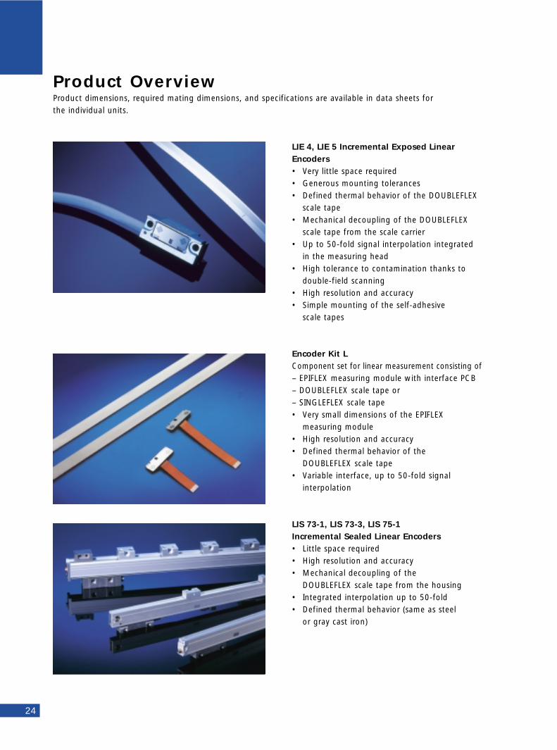
Product OverviewProduct dimensions, required mating dimensions, and specifications are available in data sheets for the individual units.
24
LIE 4, LIE 5 Incremental Exposed LinearEncoders• Very little space required• Generous mounting tolerances• Defined thermal behavior of the DOUBLEFLEX
scale tape• Mechanical decoupling of the DOUBLEFLEX
scale tape from the scale carrier• Up to 50-fold signal interpolation integrated
in the measuring head• High tolerance to contamination thanks to
double-field scanning• High resolution and accuracy• Simple mounting of the self-adhesive
scale tapes
Encoder Kit LComponent set for linear measurement consisting of – EPIFLEX measuring module with interface PCB– DOUBLEFLEX scale tape or– SINGLEFLEX scale tape• Very small dimensions of the EPIFLEX
measuring module• High resolution and accuracy• Defined thermal behavior of the
DOUBLEFLEX scale tape• Variable interface, up to 50-fold signal
interpolation
LIS 73-1, LIS 73-3, LIS 75-1Incremental Sealed Linear Encoders• Little space required• High resolution and accuracy• Mechanical decoupling of the
DOUBLEFLEX scale tape from the housing• Integrated interpolation up to 50-fold • Defined thermal behavior (same as steel
or gray cast iron)
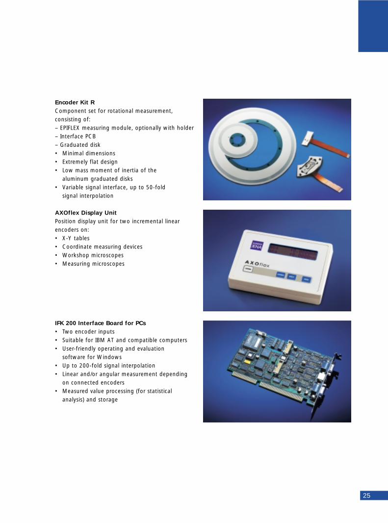
Encoder Kit RComponent set for rotational measurement, consisting of:– EPIFLEX measuring module, optionally with holder– Interface PCB– Graduated disk• Minimal dimensions• Extremely flat design• Low mass moment of inertia of the
aluminum graduated disks• Variable signal interface, up to 50-fold
signal interpolation
AXOflex Display UnitPosition display unit for two incremental linearencoders on:• X-Y tables• Coordinate measuring devices• Workshop microscopes• Measuring microscopes
IFK 200 Interface Board for PCs• Two encoder inputs• Suitable for IBM AT and compatible computers• User-friendly operating and evaluation
software for Windows• Up to 200-fold signal interpolation• Linear and/or angular measurement depending
on connected encoders• Measured value processing (for statistical
analysis) and storage
25

NUMERIK JENA GmbHIlmstrasse 407743 JenaGermanyTel.: ++49 36 41 47 28-0Fax: ++49 36 41 47 28 11e-mail: [email protected]: http.//www.numerikjena.de
Linear-D-e 02/00 Subject to change without notice