Embed Size (px)
Citation preview
Spherosyn & Microsyn Linear Encoders
NEWALL MEASUREMENT SYSTEMS LTDN
Newall Measurement Systems
Contents
Newall Measurement Systems1
CONTENTS
1. Introduction1.1 Bracketry1.2 Preparation1.3 Warnings
2. Spherosyn Encoder Assembly
3. Microsyn Encoder Assembly
4. Mounting the Reader Head4.1 Spherosyn4.2 Microsyn
5. Mounting the Scales and Support Brackets5.1 Spherosyn Scale
5.1.1 Double End Mounting5.1.2 Single End Mounting5.1.3 Scales is Excess of 2.5 metres
5.2 Microsyn Scale5.2.1 Single End Mounting
6. Mounting the scale guard
7. Cable routing
8. Final check
APPENDICES
Introduction
Newall Measurement Systems 2
1.0 INTRODUCTIONThis manual will provide mounting instructions for Newall's Spherosyn and Microsyn Linear Encoders. Itis important that you read and understand this manual prior to beginning the installation.
If at any time during the installation you should have any questions, contact Newall or your localauthorised representative.
1.1 Bracketry
Due to the variety of machine types and applications, it will be necessary to design, make and fit custombrackets for theencoder assembly. If bracketry is needed make certain they are rigid enough not toallow any flexing or distorting while the machine is in operation. Newall offers a variety of bracket kits toaid in the installation. Contact Newall or your local authorised representative for details.
1.2 Preparation
Prior to beginning the installation the machine should be studied to determine where the Encoder(s) willbe fitted. Appendix A shows several different methods of mounting the Reader Head along with itsbrackets.
In order to reduce erroneous readers caused by machine wear, it is recommended that the Scale befitted as close to the machine lead screw or axial drive shaft as possible.
The actual overall scale length is approximately 258mm (10.1”) for Spherosyn and 187mm (7.3") forMicrosyn longer than the stated scale travel. (e.g. if the travel length is 40” (Spherosyn) the actualoverall scale length of the scale will be 50”)
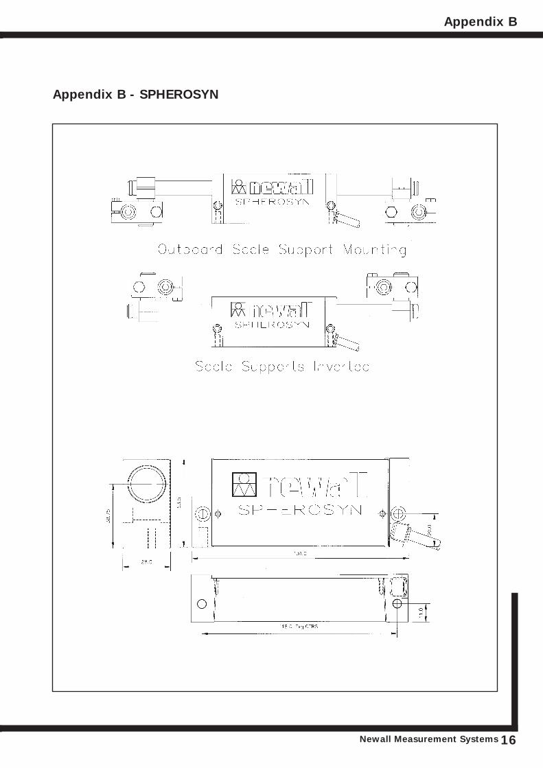
Outboard mounting of the scale support brackets will add approximately 20mm (3/4") to the effectivescale travel. (Refer to Appendix B)
For a more compact installation, scale travels of 300mm (12") or less may be fitted by supporting oneend of the scale only by use of a single end mounting block. (Refer to Figure 5.4 and 5.10)
The moving member of the Encoder assembly can be either the Reader Head or the Scale.
Cable routing from the Reader Head should be examined (See Section 7). Each Reader Head is providedwith either a 3.5 metre (11’) or 7 metre (22’) of armoured cable. Extension cables are available in 1metre (3'), 2 metre (6'), 3.5 metre (11.5'), 5 metre (16.5') and 10 metre (32') lengths. Contact Newallor your local authorised representative for details.
1.3 Warnings
If for any reason the machine axis travel is greater than the actual scale travel it is recommended that'mechanical stops' are fitted to the machine to avoid damage caused by over travel. Newall will notaccept responsibility for Scale and Reader Head damage caused by machine over travel.
Both the Reader Head and the Scale are precision made components and it is important that they arehandled with care. By design the Encoders can withstand the rigours of the harsh workshopenvironment. However, permanent damage can occur through bending or severe impact.
It is important that the Scale be kept at least 13mm (0.5") away from any magnetic bases on indicatorsor magnetic chucks.
Encoder Assembly
Newall Measurement SystemsNewall Measurement Systems3
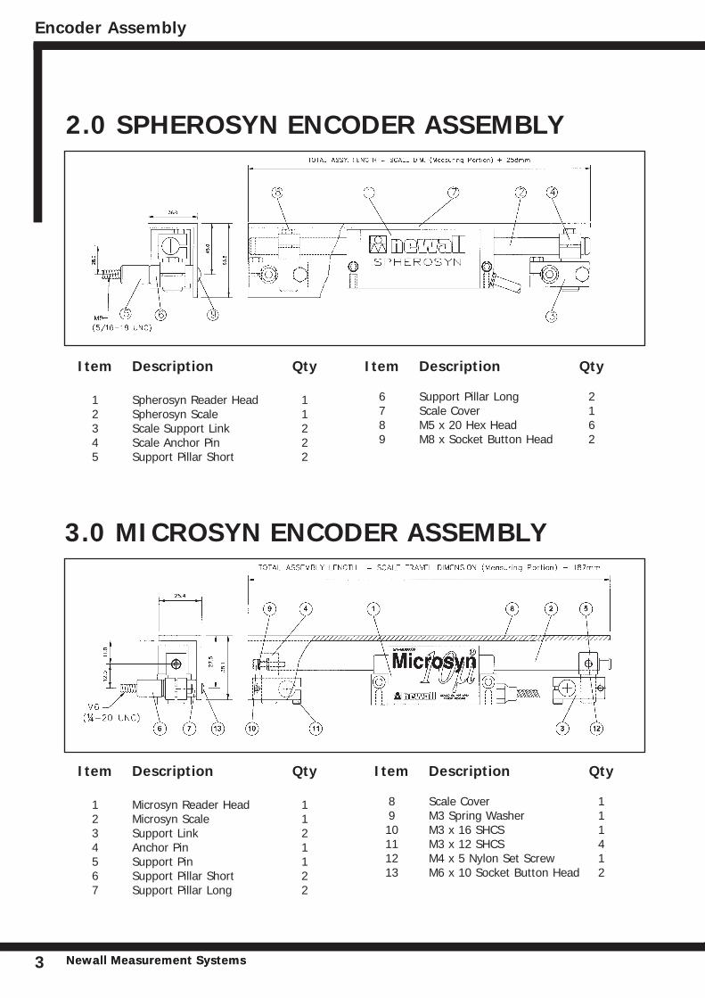
2.0 SPHEROSYN ENCODER ASSEMBLY
Item Description Qty
1 Microsyn Reader Head 12 Microsyn Scale 13 Support Link 24 Anchor Pin 15 Support Pin 16 Support Pillar Short 27 Support Pillar Long 2
Item Description Qty
8 Scale Cover 19 M3 Spring Washer 110 M3 x 16 SHCS 111 M3 x 12 SHCS 412 M4 x 5 Nylon Set Screw 113 M6 x 10 Socket Button Head 2
Item Description Qty
1 Spherosyn Reader Head 12 Spherosyn Scale 13 Scale Support Link 24 Scale Anchor Pin 25 Support Pillar Short 2
Item Description Qty
6 Support Pillar Long 27 Scale Cover 18 M5 x 20 Hex Head 69 M8 x Socket Button Head 2
3.0 MICROSYN ENCODER ASSEMBLY
Mounting the Reader Head
Newall Measurement Systems 4
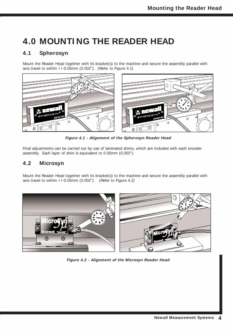
4.0 MOUNTING THE READER HEAD4.1 Spherosyn
Mount the Reader Head together with its bracket(s) to the machine and secure the assembly parallel withaxis travel to within +/-0.05mm (0.002"). (Refer to Figure 4.1)
Final adjustments can be carried out by use of laminated shims, which are included with each encoderassembly. Each layer of shim is equivalent to 0.05mm (0.002").
4.2 Microsyn
Mount the Reader Head together with its bracket(s) to the machine and secure the assembly parallel withaxis travel to within +/-0.05mm (0.002"). (Refer to Figure 4.2)
Figure 4.1 - Alignment of the Spherosyn Reader Head
Figure 4.2 - Alignment of the Microsyn Reader Head
Newall Measurement Systems
5.0 MOUNTING THE SCALE5.1 Spherosyn
5.1.1 Double End Mounting
Note: Refer to section 5.1.3 for mounting scales in excess of 2.5 metres.
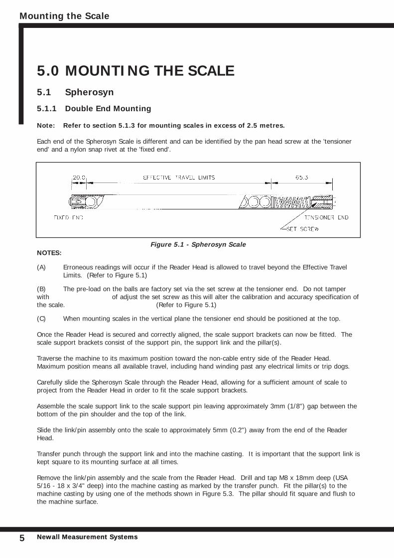
Each end of the Spherosyn Scale is different and can be identified by the pan head screw at the 'tensionerend' and a nylon snap rivet at the 'fixed end'.
NOTES:
(A) Erroneous readings will occur if the Reader Head is allowed to travel beyond the Effective Travel Limits. (Refer to Figure 5.1)
(B) The pre-load on the balls are factory set via the set screw at the tensioner end. Do not tamperwith of adjust the set screw as this will alter the calibration and accuracy specification ofthe scale. (Refer to Figure 5.1)
(C) When mounting scales in the vertical plane the tensioner end should be positioned at the top.
Once the Reader Head is secured and correctly aligned, the scale support brackets can now be fitted. Thescale support brackets consist of the support pin, the support link and the pillar(s).
Traverse the machine to its maximum position toward the non-cable entry side of the Reader Head.Maximum position means all available travel, including hand winding past any electrical limits or trip dogs.
Carefully slide the Spherosyn Scale through the Reader Head, allowing for a sufficient amount of scale toproject from the Reader Head in order to fit the scale support brackets.
Assemble the scale support link to the scale support pin leaving approximately 3mm (1/8") gap between thebottom of the pin shoulder and the top of the link.
Slide the link/pin assembly onto the scale to approximately 5mm (0.2") away from the end of the ReaderHead.
Transfer punch through the support link and into the machine casting. It is important that the support link iskept square to its mounting surface at all times.
Remove the link/pin assembly and the scale from the Reader Head. Drill and tap M8 x 18mm deep (USA5/16 - 18 x 3/4" deep) into the machine casting as marked by the transfer punch. Fit the pillar(s) to themachine casting by using one of the methods shown in Figure 5.3. The pillar should fit square and flush tothe machine surface.
Mounting the Scale
Newall Measurement Systems5
Figure 5.1 - Spherosyn Scale
Mounting the Scale
Newall Measurement Systems 6
A maximum of two support pillars may be screwed together to allow for sufficient adjustment of the scale.If two pillars are insufficient to enable the scale to be mounted, then additional brackets will be necessary.These brackets must be sufficiently rigid to eliminate any axial movement of the scale.
Loosely fit the support link/pin assembly onto the pillar and pass the scale through the Reader Head andinto the support pin. While gently sliding the scale forward and back 25 - 50mm (1" - 2") through thesupport pin, carefully tighten the hex screws on the support link, ensuring that the scale slides smoothlythrough the Reader Head and into the support pin. If any interference is detected then fully loosen the hexscrews on the support link and repeat this step.
Note: Do not force the Scale through the Support Pin
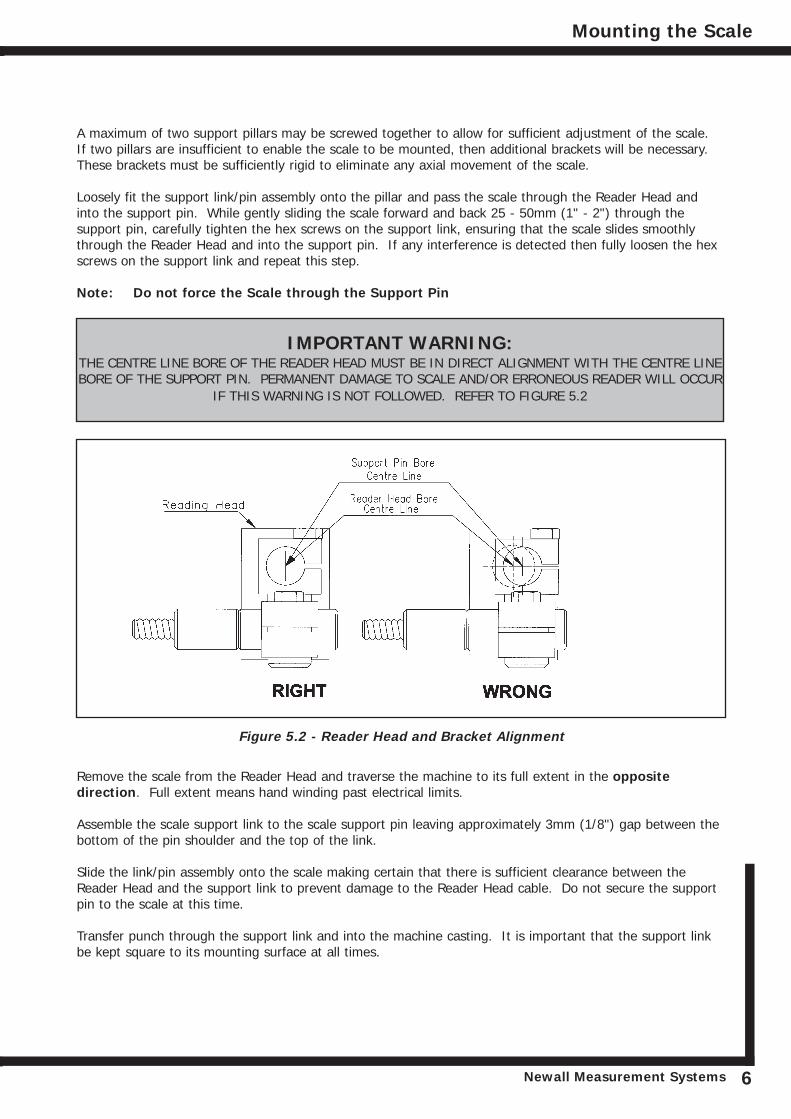
IMPORTANT WARNING: THE CENTRE LINE BORE OF THE READER HEAD MUST BE IN DIRECT ALIGNMENT WITH THE CENTRE LINEBORE OF THE SUPPORT PIN. PERMANENT DAMAGE TO SCALE AND/OR ERRONEOUS READER WILL OCCUR
IF THIS WARNING IS NOT FOLLOWED. REFER TO FIGURE 5.2
Remove the scale from the Reader Head and traverse the machine to its full extent in the oppositedirection. Full extent means hand winding past electrical limits.
Assemble the scale support link to the scale support pin leaving approximately 3mm (1/8") gap between thebottom of the pin shoulder and the top of the link.
Slide the link/pin assembly onto the scale making certain that there is sufficient clearance between theReader Head and the support link to prevent damage to the Reader Head cable. Do not secure the supportpin to the scale at this time.
Transfer punch through the support link and into the machine casting. It is important that the support linkbe kept square to its mounting surface at all times.
Figure 5.2 - Reader Head and Bracket Alignment
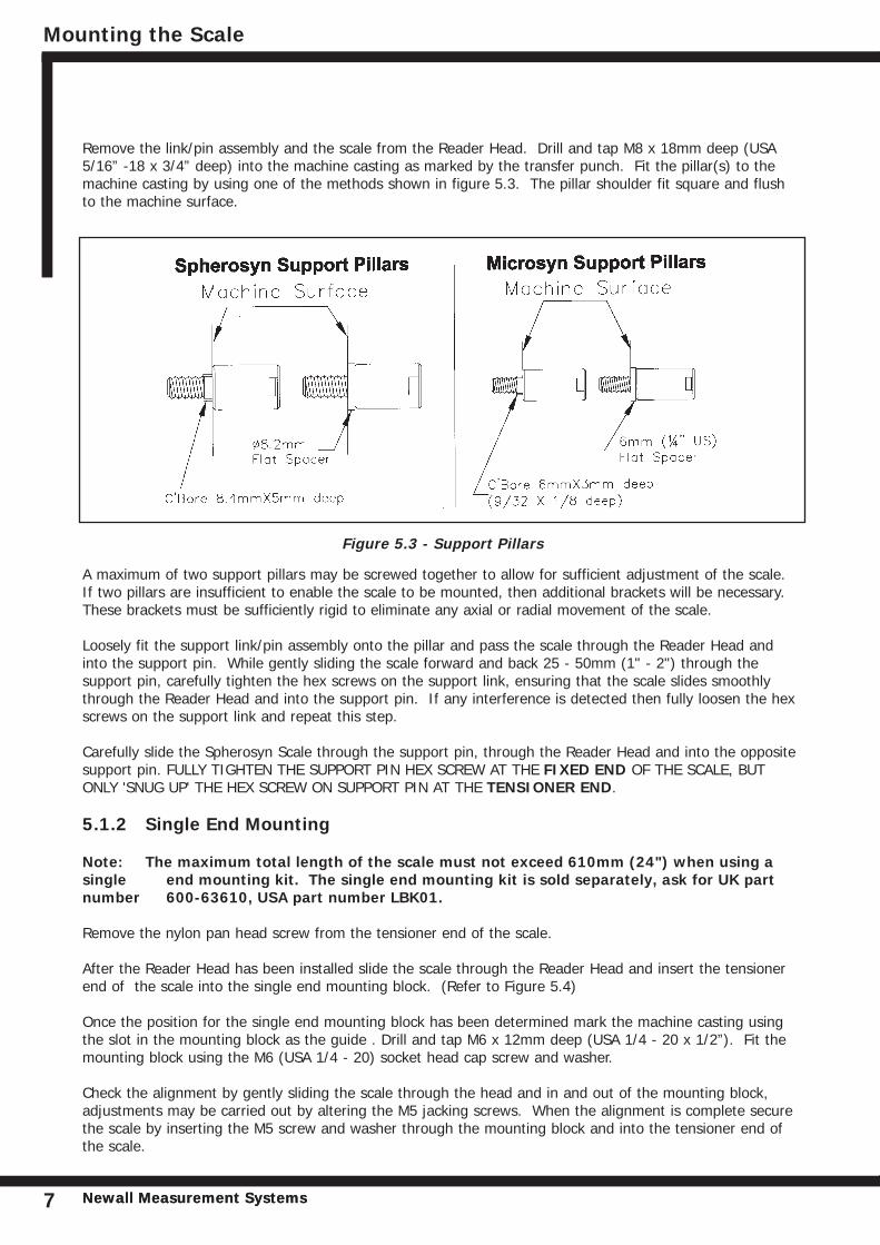
Remove the link/pin assembly and the scale from the Reader Head. Drill and tap M8 x 18mm deep (USA5/16” -18 x 3/4” deep) into the machine casting as marked by the transfer punch. Fit the pillar(s) to themachine casting by using one of the methods shown in figure 5.3. The pillar shoulder fit square and flushto the machine surface.
A maximum of two support pillars may be screwed together to allow for sufficient adjustment of the scale.If two pillars are insufficient to enable the scale to be mounted, then additional brackets will be necessary.These brackets must be sufficiently rigid to eliminate any axial or radial movement of the scale.
Loosely fit the support link/pin assembly onto the pillar and pass the scale through the Reader Head andinto the support pin. While gently sliding the scale forward and back 25 - 50mm (1" - 2") through thesupport pin, carefully tighten the hex screws on the support link, ensuring that the scale slides smoothlythrough the Reader Head and into the support pin. If any interference is detected then fully loosen the hexscrews on the support link and repeat this step.
Carefully slide the Spherosyn Scale through the support pin, through the Reader Head and into the oppositesupport pin. FULLY TIGHTEN THE SUPPORT PIN HEX SCREW AT THE FIXED END OF THE SCALE, BUTONLY 'SNUG UP' THE HEX SCREW ON SUPPORT PIN AT THE TENSIONER END.
5.1.2 Single End Mounting
Note: The maximum total length of the scale must not exceed 610mm (24") when using asingle end mounting kit. The single end mounting kit is sold separately, ask for UK partnumber 600-63610, USA part number LBK01.
Remove the nylon pan head screw from the tensioner end of the scale.
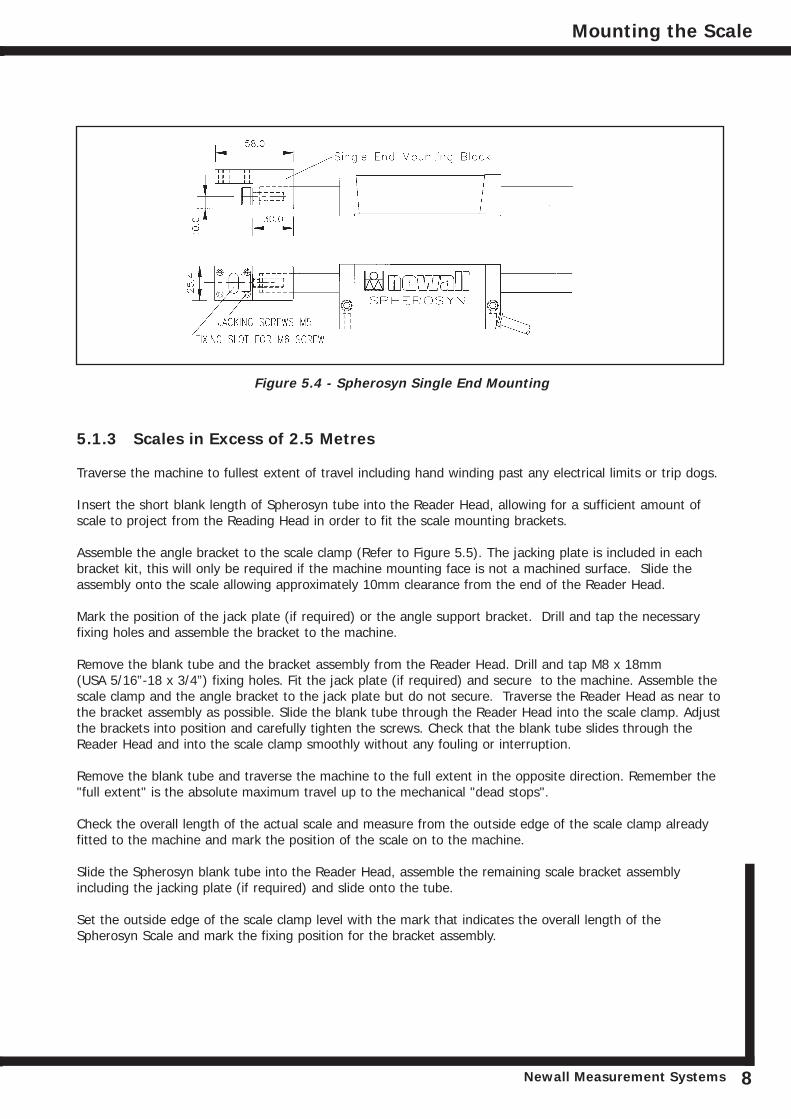
After the Reader Head has been installed slide the scale through the Reader Head and insert the tensionerend of the scale into the single end mounting block. (Refer to Figure 5.4)
Once the position for the single end mounting block has been determined mark the machine casting usingthe slot in the mounting block as the guide . Drill and tap M6 x 12mm deep (USA 1/4 - 20 x 1/2”). Fit themounting block using the M6 (USA 1/4 - 20) socket head cap screw and washer.
Check the alignment by gently sliding the scale through the head and in and out of the mounting block,adjustments may be carried out by altering the M5 jacking screws. When the alignment is complete securethe scale by inserting the M5 screw and washer through the mounting block and into the tensioner end ofthe scale.
Mounting the Scale
Newall Measurement SystemsNewall Measurement Systems7
Figure 5.3 - Support Pillars
Mounting the Scale
Newall Measurement Systems 8
5.1.3 Scales in Excess of 2.5 Metres
Traverse the machine to fullest extent of travel including hand winding past any electrical limits or trip dogs.
Insert the short blank length of Spherosyn tube into the Reader Head, allowing for a sufficient amount ofscale to project from the Reading Head in order to fit the scale mounting brackets.
Assemble the angle bracket to the scale clamp (Refer to Figure 5.5). The jacking plate is included in eachbracket kit, this will only be required if the machine mounting face is not a machined surface. Slide theassembly onto the scale allowing approximately 10mm clearance from the end of the Reader Head.
Mark the position of the jack plate (if required) or the angle support bracket. Drill and tap the necessaryfixing holes and assemble the bracket to the machine.
Remove the blank tube and the bracket assembly from the Reader Head. Drill and tap M8 x 18mm (USA 5/16”-18 x 3/4”) fixing holes. Fit the jack plate (if required) and secure to the machine. Assemble thescale clamp and the angle bracket to the jack plate but do not secure. Traverse the Reader Head as near tothe bracket assembly as possible. Slide the blank tube through the Reader Head into the scale clamp. Adjustthe brackets into position and carefully tighten the screws. Check that the blank tube slides through theReader Head and into the scale clamp smoothly without any fouling or interruption.
Remove the blank tube and traverse the machine to the full extent in the opposite direction. Remember the"full extent" is the absolute maximum travel up to the mechanical "dead stops".
Check the overall length of the actual scale and measure from the outside edge of the scale clamp alreadyfitted to the machine and mark the position of the scale on to the machine.
Slide the Spherosyn blank tube into the Reader Head, assemble the remaining scale bracket assemblyincluding the jacking plate (if required) and slide onto the tube.
Set the outside edge of the scale clamp level with the mark that indicates the overall length of theSpherosyn Scale and mark the fixing position for the bracket assembly.
Figure 5.4 - Spherosyn Single End Mounting
For scales which are mounted in the horizontal position, spring loaded scale supports are included andshould be positioned according to Table 1.
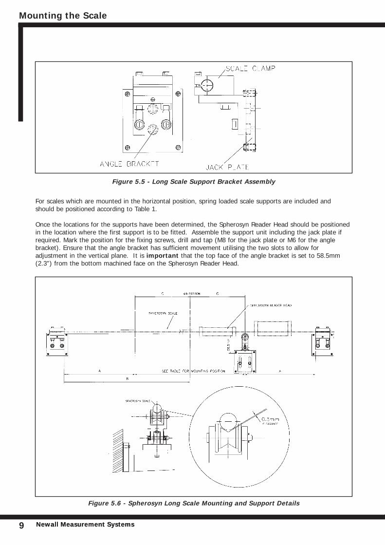
Once the locations for the supports have been determined, the Spherosyn Reader Head should be positionedin the location where the first support is to be fitted. Assemble the support unit including the jack plate ifrequired. Mark the position for the fixing screws, drill and tap (M8 for the jack plate or M6 for the anglebracket). Ensure that the angle bracket has sufficient movement utilising the two slots to allow foradjustment in the vertical plane. It is important that the top face of the angle bracket is set to 58.5mm(2.3”) from the bottom machined face on the Spherosyn Reader Head.
Mounting the Scale
Newall Measurement SystemsNewall Measurement Systems9
Figure 5.6 - Spherosyn Long Scale Mounting and Support Details
Figure 5.5 - Long Scale Support Bracket Assembly
Mounting the Scale
Newall Measurement Systems 10
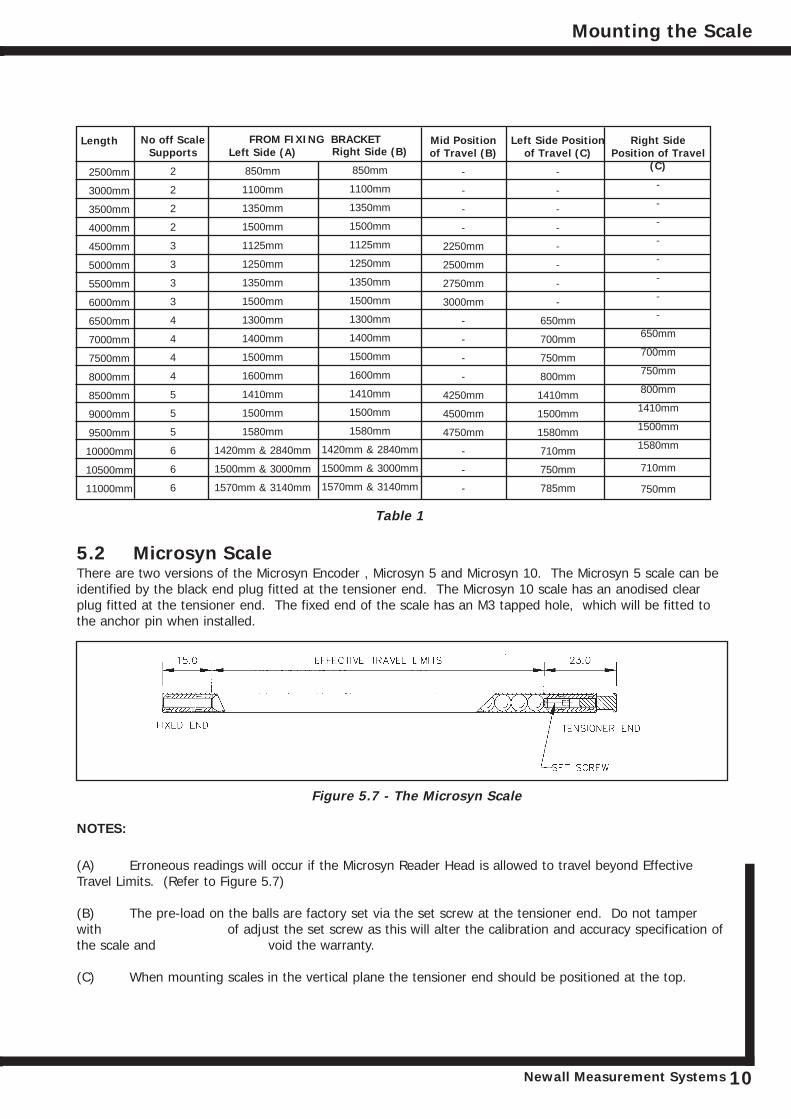
Length
2500mm
3000mm
3500mm
4000mm
4500mm
5000mm
5500mm
6000mm
6500mm
7000mm
7500mm
8000mm
8500mm
9000mm
9500mm
10000mm
10500mm
11000mm
No off ScaleSupports
2
2
2
2
3
3
3
3
4
4
4
4
5
5
5
6
6
6
Left Side (A)
850mm
1100mm
1350mm
1500mm
1125mm
1250mm
1350mm
1500mm
1300mm
1400mm
1500mm
1600mm
1410mm
1500mm
1580mm
1420mm & 2840mm
1500mm & 3000mm
1570mm & 3140mm
Right Side (B)
850mm
1100mm
1350mm
1500mm
1125mm
1250mm
1350mm
1500mm
1300mm
1400mm
1500mm
1600mm
1410mm
1500mm
1580mm
1420mm & 2840mm
1500mm & 3000mm
1570mm & 3140mm
Mid Positionof Travel (B)
-
-
-
-
2250mm
2500mm
2750mm
3000mm
-
-
-
-
4250mm
4500mm
4750mm
-
-
-
Left Side Positionof Travel (C)
-
-
-
-
-
-
-
-
650mm
700mm
750mm
800mm
1410mm
1500mm
1580mm
710mm
750mm
785mm
Right SidePosition of Travel
(C)
-
-
-
-
-
-
-
-
650mm
700mm
750mm
800mm
1410mm
1500mm
1580mm
710mm
750mm
FROM FIXING BRACKET
Table 1
5.2 Microsyn ScaleThere are two versions of the Microsyn Encoder , Microsyn 5 and Microsyn 10. The Microsyn 5 scale can beidentified by the black end plug fitted at the tensioner end. The Microsyn 10 scale has an anodised clearplug fitted at the tensioner end. The fixed end of the scale has an M3 tapped hole, which will be fitted tothe anchor pin when installed.
NOTES:
(A) Erroneous readings will occur if the Microsyn Reader Head is allowed to travel beyond Effective Travel Limits. (Refer to Figure 5.7)
(B) The pre-load on the balls are factory set via the set screw at the tensioner end. Do not tamperwith of adjust the set screw as this will alter the calibration and accuracy specification ofthe scale and void the warranty.
(C) When mounting scales in the vertical plane the tensioner end should be positioned at the top.
Figure 5.7 - The Microsyn Scale
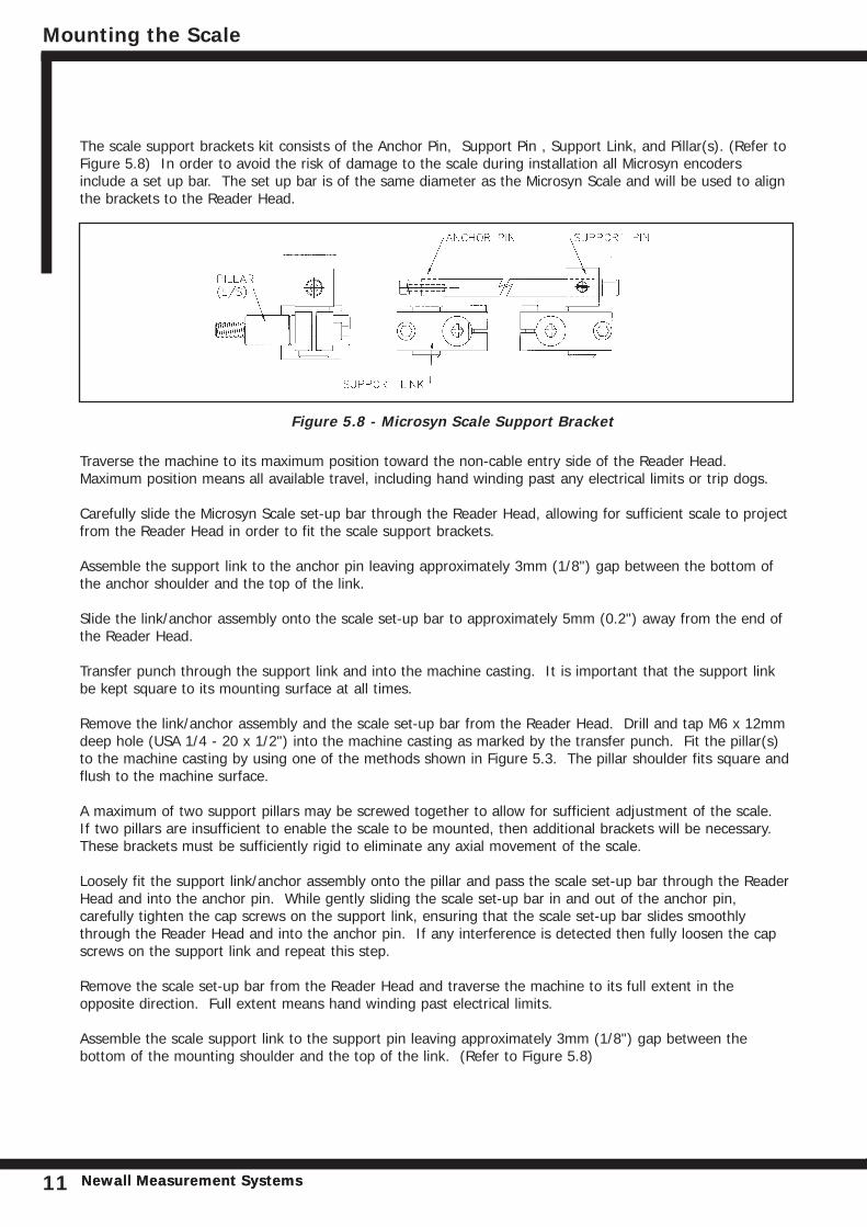
The scale support brackets kit consists of the Anchor Pin, Support Pin , Support Link, and Pillar(s). (Refer toFigure 5.8) In order to avoid the risk of damage to the scale during installation all Microsyn encodersinclude a set up bar. The set up bar is of the same diameter as the Microsyn Scale and will be used to alignthe brackets to the Reader Head.
Traverse the machine to its maximum position toward the non-cable entry side of the Reader Head.Maximum position means all available travel, including hand winding past any electrical limits or trip dogs.
Carefully slide the Microsyn Scale set-up bar through the Reader Head, allowing for sufficient scale to projectfrom the Reader Head in order to fit the scale support brackets.
Assemble the support link to the anchor pin leaving approximately 3mm (1/8") gap between the bottom ofthe anchor shoulder and the top of the link.
Slide the link/anchor assembly onto the scale set-up bar to approximately 5mm (0.2") away from the end ofthe Reader Head.
Transfer punch through the support link and into the machine casting. It is important that the support linkbe kept square to its mounting surface at all times.
Remove the link/anchor assembly and the scale set-up bar from the Reader Head. Drill and tap M6 x 12mmdeep hole (USA 1/4 - 20 x 1/2") into the machine casting as marked by the transfer punch. Fit the pillar(s)to the machine casting by using one of the methods shown in Figure 5.3. The pillar shoulder fits square andflush to the machine surface.
A maximum of two support pillars may be screwed together to allow for sufficient adjustment of the scale. If two pillars are insufficient to enable the scale to be mounted, then additional brackets will be necessary.These brackets must be sufficiently rigid to eliminate any axial movement of the scale.
Loosely fit the support link/anchor assembly onto the pillar and pass the scale set-up bar through the ReaderHead and into the anchor pin. While gently sliding the scale set-up bar in and out of the anchor pin,carefully tighten the cap screws on the support link, ensuring that the scale set-up bar slides smoothlythrough the Reader Head and into the anchor pin. If any interference is detected then fully loosen the capscrews on the support link and repeat this step.
Remove the scale set-up bar from the Reader Head and traverse the machine to its full extent in theopposite direction. Full extent means hand winding past electrical limits.
Assemble the scale support link to the support pin leaving approximately 3mm (1/8") gap between thebottom of the mounting shoulder and the top of the link. (Refer to Figure 5.8)
Figure 5.8 - Microsyn Scale Support Bracket
Mounting the Scale
Newall Measurement SystemsNewall Measurement Systems11
Mounting the Scale
Newall Measurement Systems 12
Slide the link/pin assembly onto the scale set-up bar making certain that there is sufficient clearancebetween the Reader Head and the support link to prevent damage to the Reader Head cable. Do not securethe support pin to the scale at this time.
Transfer punch through the support link and into the machine casting. It is important that the support linkbe kept square to its mounting surface at all times.
Remove the link/pin assembly and the scale from the Reader Head. Drill and tap M6 x 12mm deep (USA 1/4- 20 x 1/2 deep) into the machine casting as marked by the transfer punch. Fit the pillar(s) to the machinecasting by using one of the methods shown in Figure 5.3. The pillar shoulder fit square and flush to themachine surface.
Loosely fit the support link/pin assembly onto the pillar and pass the scale set-up bar through the ReaderHead and into the support pin. While gently sliding the set-up bar forward and back 25 - 50mm (1" - 2")through the support mounting, carefully tighten the screws on the support link, ensuring that the scale set-up bar slides smoothly through the Reader Head and into the support pin. If any interference is detectedthen fully loosen the screws on the support link and repeat this step.
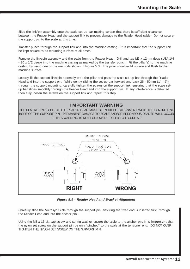
IMPORTANT WARNING THE CENTRE LINE BORE OF THE READER HEAD MUST BE IN DIRECT ALIGNMENT WITH THE CENTRE LINEBORE OF THE SUPPORT PIN. PERMANENT DAMAGE TO SCALE AND/OR ERRONEOUS READER WILL OCCUR
IF THIS WARNING IS NOT FOLLOWED. REFER TO FIGURE 5.9
Carefully slide the Microsyn Scale through the support pin, ensuring the fixed end is inserted first, throughthe Reader Head and into the anchor pin.
Using the M3 x 16 skt cap screw and spring washer, secure the scale to the anchor pin. It is important thatthe nylon set screw on the support pin be only “pinched” to the scale at the tensioner end. DO NOT OVERTIGHTEN THE NYLON SET SCREW ON THE SUPPORT PIN.
Figure 5.9 - Reader Head and Bracket Alignment
Mounting the Scale / Fitting the Scale Guard
Newall Measurement SystemsNewall Measurement Systems13
5.2.1 Single End Mounting
For installations requiring a lower profile assembly, there is an alternative method for fixing the scale at oneend only by way of the single end mounting block assembly (Refer to Figure 5.10). The Microsyn single endmounting kit is sold separately, as for UK part number 600-65340, US part number LBK02 (for Spherosyn &Microsyn) and LBK03 (for Microsyn only).
Note: The maximum total length of scale not exceed 450mm (18") when using the single endmounting block.
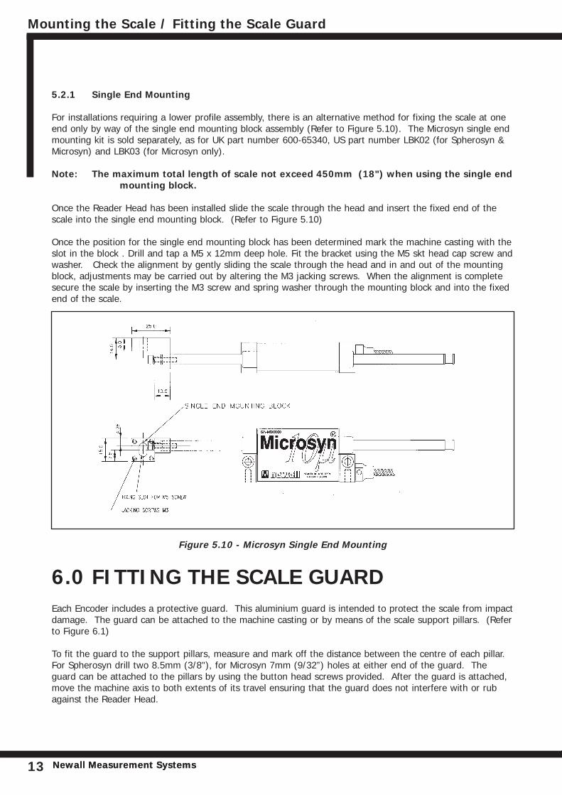
Once the Reader Head has been installed slide the scale through the head and insert the fixed end of thescale into the single end mounting block. (Refer to Figure 5.10)
Once the position for the single end mounting block has been determined mark the machine casting with theslot in the block . Drill and tap a M5 x 12mm deep hole. Fit the bracket using the M5 skt head cap screw andwasher. Check the alignment by gently sliding the scale through the head and in and out of the mountingblock, adjustments may be carried out by altering the M3 jacking screws. When the alignment is completesecure the scale by inserting the M3 screw and spring washer through the mounting block and into the fixedend of the scale.
Figure 5.10 - Microsyn Single End Mounting
6.0 FITTING THE SCALE GUARDEach Encoder includes a protective guard. This aluminium guard is intended to protect the scale from impactdamage. The guard can be attached to the machine casting or by means of the scale support pillars. (Referto Figure 6.1)
To fit the guard to the support pillars, measure and mark off the distance between the centre of each pillar.For Spherosyn drill two 8.5mm (3/8"), for Microsyn 7mm (9/32”) holes at either end of the guard. Theguard can be attached to the pillars by using the button head screws provided. After the guard is attached,move the machine axis to both extents of its travel ensuring that the guard does not interfere with or rubagainst the Reader Head.
Fitting the Scale Guard / Cable Routing / Final Check
Newall Measurement Systems 14
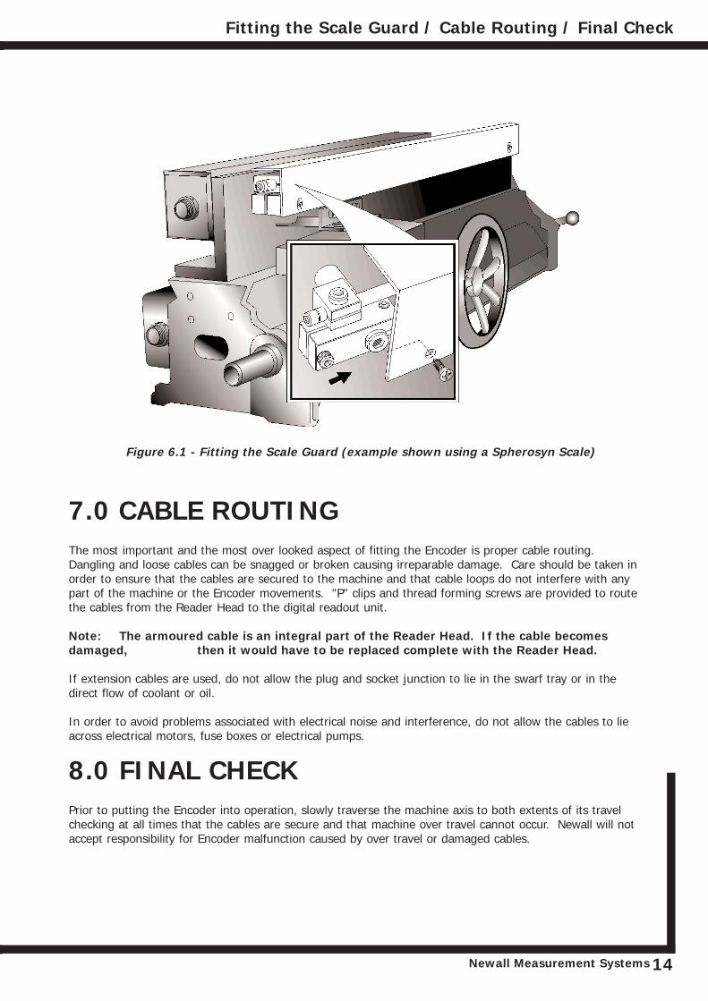
Figure 6.1 - Fitting the Scale Guard (example shown using a Spherosyn Scale)
7.0 CABLE ROUTINGThe most important and the most over looked aspect of fitting the Encoder is proper cable routing.Dangling and loose cables can be snagged or broken causing irreparable damage. Care should be taken inorder to ensure that the cables are secured to the machine and that cable loops do not interfere with anypart of the machine or the Encoder movements. "P" clips and thread forming screws are provided to routethe cables from the Reader Head to the digital readout unit.
Note: The armoured cable is an integral part of the Reader Head. If the cable becomes damaged, then it would have to be replaced complete with the Reader Head.
If extension cables are used, do not allow the plug and socket junction to lie in the swarf tray or in thedirect flow of coolant or oil.
In order to avoid problems associated with electrical noise and interference, do not allow the cables to lieacross electrical motors, fuse boxes or electrical pumps.
8.0 FINAL CHECKPrior to putting the Encoder into operation, slowly traverse the machine axis to both extents of its travelchecking at all times that the cables are secure and that machine over travel cannot occur. Newall will notaccept responsibility for Encoder malfunction caused by over travel or damaged cables.
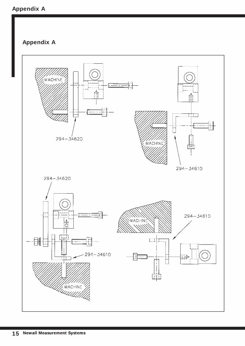
Appendix A
Newall Measurement SystemsNewall Measurement Systems15
Appendix A
Appendix B
Newall Measurement Systems 16
Appendix B - SPHEROSYN
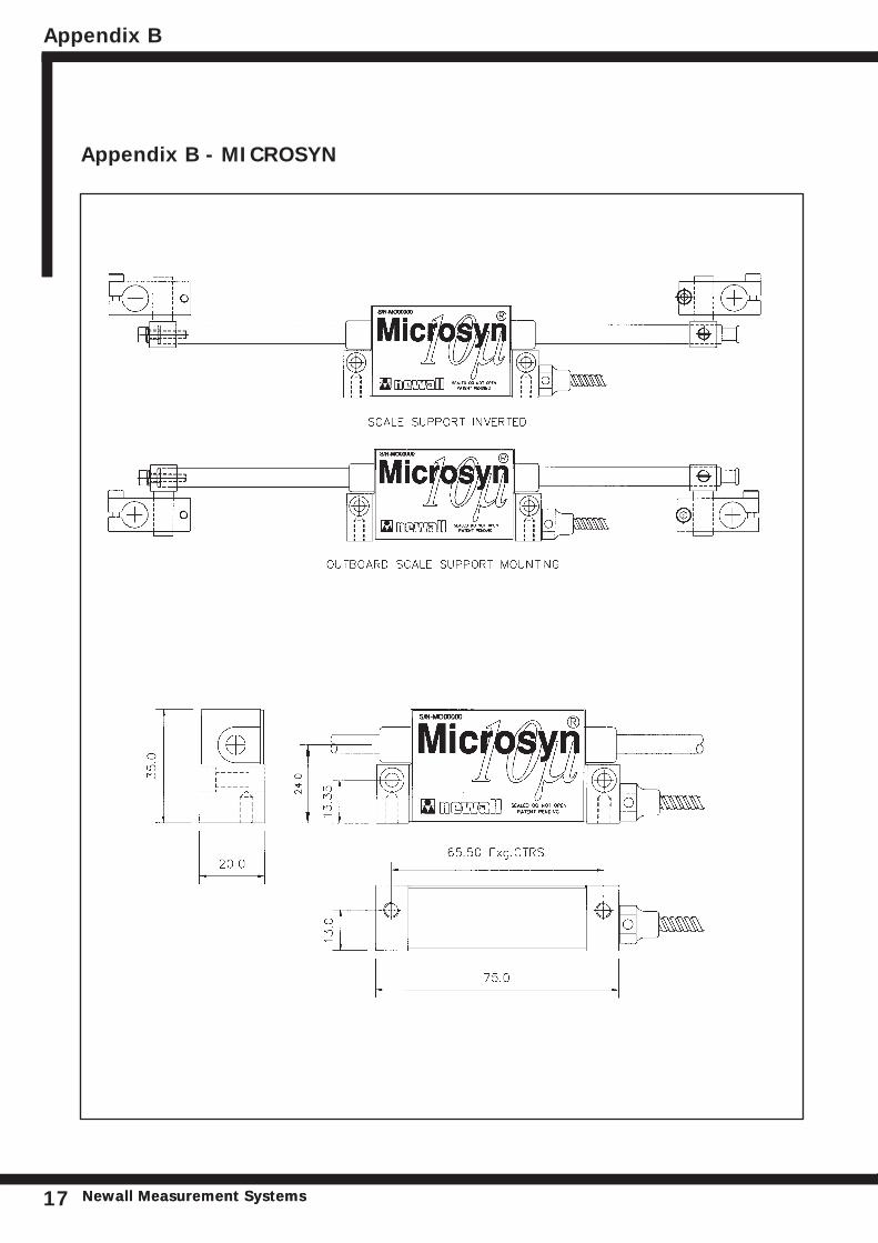
Appendix B - MICROSYN
Appendix B
Newall Measurement SystemsNewall Measurement Systems17

NEWALL MEASUREMENT SYSTEMS LTD
023-12620-UK . June 2004
HEAD OFFICENewall Measurement Systems Ltd.
Technology Gateway, Cornwall RoadSouth Wigston
Leicester LE18 4XHUnited Kingdom
Telephone: +44 (0)116 264 2730Facsimile: +44 (0)116 264 2731
Email: [email protected]: www.newall.co.uk
Newall Electronics, Inc.1778 Dividend DriveColumbus, OH 43228
Telephone: +1 614 771 0213Toll Free: 800.229.4376
Facsimile: +1 614 771 0219Email: [email protected]: www.newall.com
Newall France SARL63 Rue Victor HugoF-59200, Tourcoing
FRANCETelephone: +33 (0) 3 20 01 03 13Facsimile: +33 (0) 3 20 26 13 41
Email: [email protected]
Newall DeutschlandPostfach 20
72117 AmmerbuchGERMANY
Telefon: +49 (0) 7073 302908Fax: +49 (0) 7073 302963
Email: manfred.friebe.newall.co.uk