Embed Size (px)
Citation preview

1
Libero™ Integrated Design Environment
Actel CorporationMountain View, CA – USA
© 2005 Actel Corp. 2Libero™ IDE July, 2005
Outline
� Session 1: Introduction to Actel productsLibero IDE overview and design flowDesign entry
� Session 2: Functional simulationSynthesis
� Session 3: Place & Route
� Session 4: Post-Layout simulationProgramming

2
Introduction to Actel Products
© 2005 Actel Corp. 4Libero™ IDE July, 2005
Actel Commercial Product Spectrum
Markets
Density
CPLD
Equivalent
Economy
FPGA
Full
Featured
FPGA
eX250 MHz
eX250 MHz
Axcelerator>500MHz
Axcelerator>500MHz
ProASICPLUS
150MHz
ProASICPLUS
150MHz
3,000 10,000 100,000 1M 2M
ProASIC100 MHZ
ProASIC100 MHZ
SX-A250 MHz
SX-A250 MHz

3
© 2005 Actel Corp. 5Libero™ IDE July, 2005
FPGA Technologies Compared
SRAM
6T
Flash
1T
Antifuse
Reprogrammable
Best of Both Worlds
Reprogrammable
& Nonvolatile
Nonvolatile
© 2005 Actel Corp. 6Libero™ IDE July, 2005
Flash Product Offering
� Benefits of flash FPGA technology
� Lowest power in its class
� In-system programmable
� Non-volatile
� Single-chip
� Lowest system cost
Product K Gates Max I/O Leading features
ProASIC 475 440 ISP, 2P-RAM/FIFO, FlashLock, Mixed 2.5V/3.3 I/O
ProASICPLUS 1000 712 ISP, 2P-RAM/FIFO, PLLs, LVPECL, FlashLock
Product K Gates Max I/O Leading features
ProASIC 475 440 ISP, 2P-RAM/FIFO, FlashLock, Mixed 2.5V/3.3 I/O
ProASICPLUS 1000 712 ISP, 2P-RAM/FIFO, PLLs, LVPECL, FlashLock

4
© 2005 Actel Corp. 7Libero™ IDE July, 2005
Antifuse Product Offering
� Benefits of antifuse FPGA technology
� High performance
� Low power
� Single-chip
� High utilization/100% pin locking
Product K Gates Max I/O Leading features
SX-A 108 360 350MHz, 64/66 PCI, 2.5/3.3/5V Hot Swap I/O
eX 12 130 Single-chip FPGA offered at CPLD densities
MX 54 202 Best 5 volt solution, Embedded block RAM
RTSX-S 108 205 SEU immune with built-in TMR
Axcelerator 2000 684 500MHz core/FIFO, 1GHz PLL, LVDS I/O
� Secure FuseLock Technology
� Live at power-up
� Cost effective
� Firm error resistant
Libero IDE Overview and Design Flow

5
© 2005 Actel Corp. 9Libero™ IDE July, 2005
Libero IDE Overview
� Complete Toolset for Actel FPGA Development
� Project Manager
� ViewDraw Schematic Capture
� Synplify Synthesis
� Testbench Generation
� Mentor ModelSim Simulation
� PALACE Physical Synthesis (Libero Platinum)
� Actel Designer Design Implementation
� Compile, Place & Route
� Timing and Physical Constraints
� Timing Analysis
� Power Analysis
� Back Annotation
� Programming File Generation
� FlashPro Programming Software
� Silicon Explorer Debug Software
© 2005 Actel Corp. 10Libero™ IDE July, 2005
Libero Tool Suite
•Integrated Design
Environment
Design
Implementation
• Synthesis
Synplify
ViewDraw AE
•Schematic Capture
Actel
• ACTgen Macro builder
Design
Verification
• Stimulus
SynaptiCAD
ModelSim
•Simulation
• Silicon Explorer Debugger
Actel
Physical
Implementation
Actel Designer
•Programming
FlashPro
PALACE
•Physical Synthesis
•Place & Route

6
© 2005 Actel Corp. 11Libero™ IDE July, 2005
Libero Project Manager Features
� Centrally Manages and Integrates Files and Tools
� Coordinates Project Information between Tools
� e.g., Family Is Selected Once and Communicated to All Tools
� Provides Seamless Piping of Internal Design Files among Tools
� From within Libero’s Project Manager, User Can Invoke Tools for:
� Design Entry
� Stimulus Generation
� Simulation
� Synthesis
� Design Implementation and Static Timing Analysis
© 2005 Actel Corp. 12Libero™ IDE July, 2005
�Design Explorer Window
� Design Hierarchy Tab Displays Hierarchical Representation of Source Files in Project
� Libero Continuously Analyzes and Updates Hierarchy
� File Manager Tab Displays All Files in Project Grouped by Type
�Language-Sensitive HDL Editor
� Verilog 95 or VHDL 93
�Tools Can Be Launched from Design Flow Window or Process Window
�Log Windows Provide Status and Error Messages
Libero IDE Project Manager
Log Window Error Manager
Status Bar
DesignExplorerWindow
HDL pane

7
© 2005 Actel Corp. 13Libero™ IDE July, 2005
Libero IDE Design Flow Window
� Flow Window Displayed in HDL Pane
� Tabs Switch between Flow Window and HDL Window
© 2005 Actel Corp. 14Libero™ IDE July, 2005
Libero IDE Design Flow Window
� Design Flow Window Displays:
� Tools
� Files
� Transitions
� Current State
� Tool Tips
� Interactive Blocks
� Activates Tools
� View Files
� Display changes dynamically based on target family
Step-by-Step design flow decreases design development timeCurrent state of design

8
© 2005 Actel Corp. 15Libero™ IDE July, 2005
File Status of Displayed Items
� Group of Files Can Be …
� … Missing
� If ANY Are Missing, Block Is Shadowed Out
� … Available and Current
� Green Check Mark Is Shown
� … Available, but Not Current
� If at Least One is Not Current, Warning Icon Is Displayed
Synthesis Complete
Source Modified –EDIF Netlist not current
Synthesis Incomplete
© 2005 Actel Corp. 16Libero™ IDE July, 2005
Tool States
� Disabled => Button Is Shadowed
� White => Available, but Not Yet Used
� Green => Completed Successfully
� Red => Error in Running Tool
Synthesis Succeeded
Synthesis Failed

9
© 2005 Actel Corp. 17Libero™ IDE July, 2005
Libero IDE View Options
� Displayed Windows Turned On or Off Using Libero “View” Menu
© 2005 Actel Corp. 18Libero™ IDE July, 2005
Libero Log Window Error Manager
� Error Manager Consists of 4 Tabs in Log Window:
� All: Displays All Messages
� Errors: Displays Error Messages
� Warnings: Displays Warning Messages
� Info: Displays Information Messages
� Default Colors:
� Red => Errors
� Blue => Hyperlinks
� Light Blue => Warnings
Libero error manager tabs
Icon appears next to each message
Right
Mouse
Click!
Click in window to clear or copy text

10
© 2005 Actel Corp. 19Libero™ IDE July, 2005
Libero Software Updates
� Manually Check for Software Updates from Help Menu
� Configure Libero to Automatically Check for Software Updates from Preferences Tab (File > Preferences)
© 2005 Actel Corp. 20Libero™ IDE July, 2005
Libero IDE New Project Wizard
� Menu-Driven Wizard
� File > New Project
� Status Guide Shows Current State
� All Fields Must Be Filled in to Continue
� HDL Type Must Be Consistent with License
� Next Button Goes to Next Wizard Screen
� Finish Button Finishes/Closes Wizard after Making Changes. Saves All Selections.
Use Browse button to change project location

11
© 2005 Actel Corp. 21Libero™ IDE July, 2005
Libero IDE New Project Wizard: Select Device
� Select Family
� After Family Is Selected, Devices from that Family Are Displayed
� After Device Is Selected, Available Packages for that Device Are Displayed
© 2005 Actel Corp. 22Libero™ IDE July, 2005
Libero IDE New Project Wizard: Select Tools
� Synthesis
� Vendor (e.g. Synplify)� Version
� Physical Synthesis
� PALACE� Version
� Testbench Generation
� WaveFormer Lite� Select Version
� Simulation
� ModelSim� Select Version
� Support for Mentor Graphic’s LeonardoSpectrum and Precision
� Standard Tools Direct from Mentor� No Actel OEM Versions
� Licensing and Technical Support Directly from Mentor

12
© 2005 Actel Corp. 23Libero™ IDE July, 2005
Libero IDE New Project Wizard: Add Files
� Add Existing Design Files to Project
� Schematics, Symbols, HDL (VHDL or Verilog), Stimulus (VHDL or Verilog), ACTgen Macros or EDIF Netlists
Select file type
Browse to file location
© 2005 Actel Corp. 24Libero™ IDE July, 2005
Libero IDE New Project Wizard: Finish
� Project Information Listed in Dialog Box
� Click “Finish” to Complete Project Creation or “Back” to Make Corrections or Additions
Project summary shown in window

13
© 2005 Actel Corp. 25Libero™ IDE July, 2005
Libero project file
Default folder forLibero projects
Organization of Libero Project Files
© 2005 Actel Corp. 26Libero™ IDE July, 2005
Libero IDE Project Startup
� Default Operation
� Upon Launch of Libero, Most Recent Project Is Opened
� If No Project in Most Recently Used List, Libero Launches the New Project Wizard
� Default Controlled in Startup Properties
� Choose “Preferences” under “File”Menu
� Choose “Startup” Tab
� Check or Uncheck “Open the most recently used project at startup”

14
© 2005 Actel Corp. 27Libero™ IDE July, 2005
Libero Project Manager: Design Implementations
� Create Project Variations
� Save Different Project Views for Comparison
� Requires .adb file, Back-annotated File, Programming/Debugging File, or Post-layout Simulation Folder
© 2005 Actel Corp. 28Libero™ IDE July, 2005
Libero Project Manager: Design Implementations
� Add, Rename or remove design implementations

15
© 2005 Actel Corp. 29Libero™ IDE July, 2005
Libero Project Manager: Design Implementations
� Implementations
� Making Changes in Current View Can Change State of Project
� Pre-Synthesis
� Post-Synthesis
� Post-Physical Synthesis
� Affects All Other Views
� Changing Implementation Files for Current View Does Not Affect Other Views
© 2005 Actel Corp. 30Libero™ IDE July, 2005
Importing Files
� File -> Import Files
� Existing Design Files Can Be Imported into Libero Project
� Schematics, Symbols, HDL (VHDL or Verilog), Stimulus (VHDL or Verilog), ACTgen Macros, EDIF Netlists, SDC Files, Constraint Files, Tool Profiles� Constraint Files NOT Automatically Sent to External Tools
Schematics (*.[1-9]*)
Symbols (*[1-9]*)
Vhdl Sources (*.vhd, *.vhdl)
Vhdl Package Files (*.vhd, *.vhdl)
ACTgen Macros (*.gen)
Stimulus Files (*.vhd, *.vhdl)
Edif Netlists (*.edn)
SDC file (*.sdc)
Gatefield Constraint files (*.gcf)
Tool Profiles (*.ini)
Select file type frompull-down menu

16
© 2005 Actel Corp. 31Libero™ IDE July, 2005
Import Files: File Manager Tab
� Files Can Also Be Imported from File Manager Tab
� Click on File Type and Select Import
Right
Mouse
Click!
© 2005 Actel Corp. 32Libero™ IDE July, 2005
Deleting Files from Libero Project
� Files Can Be Deleted from Project and from HDD
� Files Deleted from HDD Cannot Be Recovered!
Right
Mouse
Click!

17
© 2005 Actel Corp. 33Libero™ IDE July, 2005
Design Hierarchy Tab: Block Properties
� Block Properties Dialog Box Displays File Path, Date Created and Last Modified Date
Right
Mouse
Click!
© 2005 Actel Corp. 34Libero™ IDE July, 2005
Libero Project Manager Include Modules for Simulation
� Libero Only Passes Top-level Source-related Modules to Simulation
� If Other Source Modules Are Required for Simulation, Check Box on File Properties
Check to include file in simulation

18
© 2005 Actel Corp. 35Libero™ IDE July, 2005
Unknown Hierarchy
� Libero Displays Files in “Default Configuration” Tree
� Missing Files Indicated with “?”
� When Libero Cannot Determine Hierarchy, Files Are Shown with “X”under Unknown Hierarchy on Design Hierarchy Tab
� Files also Shown with “X” on File Manager Tab
� Examine these Files to Correct Problem or Remove File from Project
© 2005 Actel Corp. 36Libero™ IDE July, 2005
Package Files Compile Order
� Package Files Displayed on Libero IDE File Manager Tab
� VHDL Packages
� Verilog Include Files
� Use Package Files Order Window to Indicate if Packages Are for Simulation, Synthesis or Both and to Set Compile Order
� Use Up or Down Arrows to Change Compile Order
� Check Boxes to Compile Packages for Simulation, Synthesis, or Both
� Select Options => Package Files Organization, or Right Click in Design Hierarchy Window

19
© 2005 Actel Corp. 37Libero™ IDE July, 2005
Libero Project ManagerFind Module
� To find Module in a Hierarchy, click Find Module Icon on Tool bar, or Click Edit/Find Module
Libero selects and displays the found module
© 2005 Actel Corp. 38Libero™ IDE July, 2005
Find in Files
� Edit => Find in Files, or Toolbar Icons
� Search for Files, Words, etc
� Specify by File Types
� Specify where to Search
� Match Whole Word
� Match Case
� Regular Expression
� Results Shown in “Find in Files” Tab in Log Window

20
© 2005 Actel Corp. 39Libero™ IDE July, 2005
Find in FilesCross Probing
� Selecting File Name Presented in Find in Files Log Window …
� … Opens Selected File in Libero Text Editor
� … Highlights Match
© 2005 Actel Corp. 40Libero™ IDE July, 2005
Libero IDE Project Settings
� Users can change device and specify simulation and programming options
� Options > Project Settings
� Device - change FPGA die or package
� Simulation - specify simulation options
� “Compile VHLD Package Files”option is on by default
� Programming – specify location of programming file and software

21
© 2005 Actel Corp. 41Libero™ IDE July, 2005
OEM Tools SupportTool Profiles
� Create or Edit Tool Profile for Project
� Options > Profiles
� Select Third-Party Tools & Versions
� Synthesis
Vendor (e.g. Synplify)
Version
� Physical Synthesis
PALACE
Version
� Simulation
ModelSim
Select Version
� Testbench Generation
WaveFormer Lite
Select Version
� Name Profile and Save
� Edit or Add Profiles As Needed
© 2005 Actel Corp. 42Libero™ IDE July, 2005
Add / Edit Tool Profiles
� Add/Edit Profile Requires
� … Name of Profile
� … Choosing Tool
� From Drop-down Menu
� Choose Version
� … Choosing Tool Location
� Browse for Location
� Specify Location

22
© 2005 Actel Corp. 43Libero™ IDE July, 2005
Profile Conflict
� Occurs when Current Profile Settings Are Different from those of Previous Project that is Opened
� May Have Newer Version Selected when Opening Project Created with an Older Version
© 2005 Actel Corp. 44Libero™ IDE July, 2005
Libero IDEOther Features
� Save Project to Different Name
� “Save-As” Enables Saving Project with Different Name and/or in Different Location
� Text Editor Selection
� Use Libero IDE Text Editor or External Text Editor
� File > Preferences Text Editor Tab
� Drag-Drop
� Dragging and Dropping Libero .prj File in Libero Window Opens Project File
Enter location of external text editor if selected

23
© 2005 Actel Corp. 45Libero™ IDE July, 2005
� HTML-based Help System
� Help Available for Error Messages, Specific Screens and Menus
� Expanded Content
� Hyperlinks to Application Notes and Actel Web Pages
� Help Menu Provides Direct Access to All Libero PDF Reference Manuals
Libero IDE Online Help
Design Entry

24
© 2005 Actel Corp. 47Libero™ IDE July, 2005
Design Entry
� Libero Supported Design Flows
� Structural Schematic Flow
� Mixed-Mode Flow
� HDL Flow
� ACTgen Macro Builder
� ViewDraw Overview
� Schematic Design Entry Tool
Libero Design Flows

25
© 2005 Actel Corp. 49Libero™ IDE July, 2005
Libero Design Flows
� Structural Schematic Flow
� Contains only Actel ViewDraw Library Components or Mix of Actel ViewDraw Library Components and Structural HDL
� Top Level Must Be Schematic!
� Synthesis Optional before Layout
� Mixed-Mode Flow
� Schematic and RTL Blocks
� May also Contain Structural HDL Blocks
� Top Level Must Be Schematic!
� Synthesis Required before Layout
� HDL Flow
� VHDL or Verilog (not both)
� May Contain Structural Blocks
ACTgen Macro Builder

26
© 2005 Actel Corp. 51Libero™ IDE July, 2005
ACTgen Macro Builder
� Create Macro Functions from User’s Parameters
� Optimized for Actel Architecture
� High Speed
� Small Area
� Rule-based Generation Guarantees Functional Accuracy
� Outputs:
� VHDL - Behavioral and Structural
� Verilog -Behavioral and Structural
© 2005 Actel Corp. 52Libero™ IDE July, 2005
Using ACTgen within Libero
� ACTgen Macros Can Be Used in …
� … Structural Schematic flow
� … Mixed-mode Flow
� … HDL Flow
� Steps:
� Launch ACTgen from Libero IDE Project Manager
� Create HDL Structural Implementation
� VHDL or Verilog
� HDL Flow
� Instantiate Macro in Top-level RTL
� Structural Schematic and Mixed-mode Flows
� Create ViewDraw Symbol from Libero
� instantiate Symbol in Schematic

27
© 2005 Actel Corp. 53Libero™ IDE July, 2005
ACTgen icon
Launching ACTgen from Libero
© 2005 Actel Corp. 54Libero™ IDE July, 2005
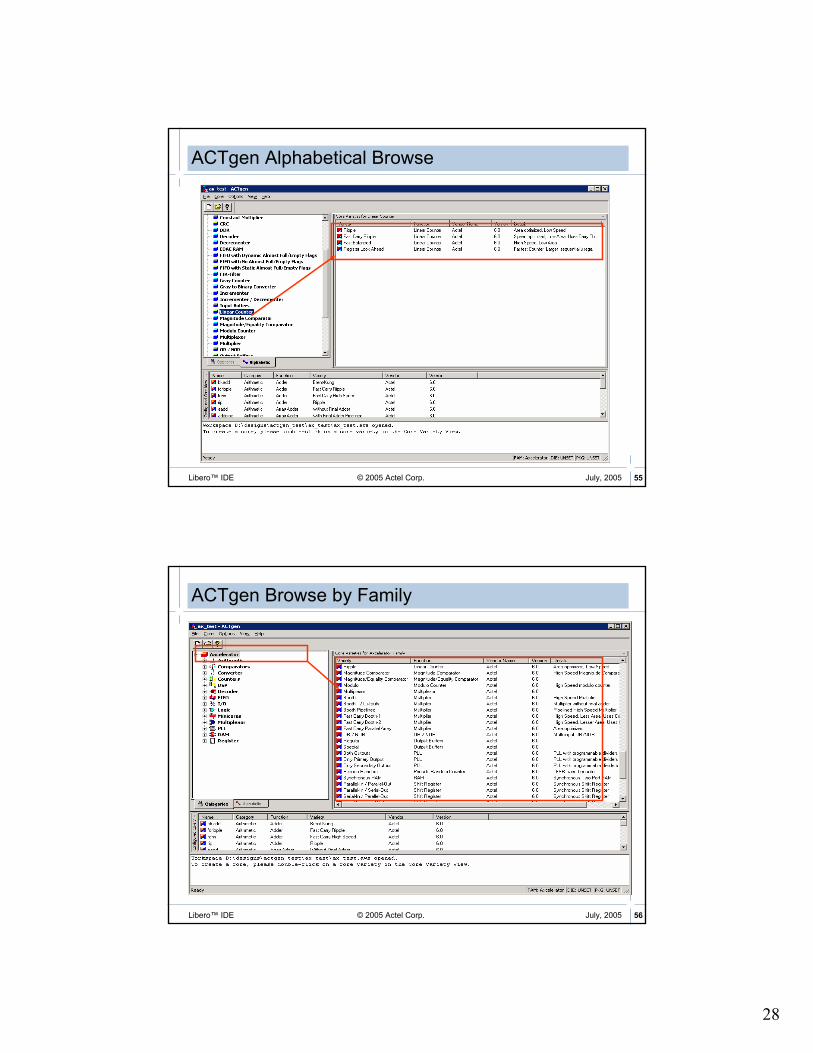
ACTgen User Interface
Core
detailsVersion #
Shows Categories
Based on Selected
FamilyView by category
or alphabeticallyVersion of selected or
configured core
View selected and
configured cores for
project
28
© 2005 Actel Corp. 55Libero™ IDE July, 2005
ACTgen Alphabetical Browse
© 2005 Actel Corp. 56Libero™ IDE July, 2005
ACTgen Browse by Family

29
© 2005 Actel Corp. 57Libero™ IDE July, 2005
2. Select type and variation
ACTgenCounter Example
1. ChooseFunction
© 2005 Actel Corp. 58Libero™ IDE July, 2005
4. Complete therest of thedescription
ACTgenCounter Example
3. Enter width
5. Click Generate
Optional Fan-In Control

30
© 2005 Actel Corp. 59Libero™ IDE July, 2005
ACTgen Buffering Control
� Users Can Control Buffering in ACTgen Macros
� Control Net Loading or Eliminate Buffering
© 2005 Actel Corp. 60Libero™ IDE July, 2005
Component Generation
Files appear on Libero File Manager tab
Output format
Generate behavioral VHDL or Verilog
Macro name
31
Structural Schematic Designs
© 2005 Actel Corp. 62Libero™ IDE July, 2005
Structural Schematic Design Flow
Programming
Place & Route
Post-P&R Simulation
Pre-Layout
Simulation
Design Capture
Generate
Structural Netlist

32
© 2005 Actel Corp. 63Libero™ IDE July, 2005
Design Capture
Programming
Place & Route
Post-P&R Simulation
Pre-Layout
Simulation
Design Capture
Generate
Structural Netlist
ViewDraw Overview
Schematic Design Entry Tool
33
© 2005 Actel Corp. 65Libero™ IDE July, 2005
ViewDrawFeatures
� Powerful Editing Capabilities
� Simple, Push-Button GUI Enables Rapid Design Input
� Infinite Undo/Redo
� Dynamic Pan and Autoscroll
� Automatic Connection of Abutting Pins
� Rubber Banding of Connected Nets with Dynamic Redraw
� Flexible and Customizable
� Designers can Add, Delete, or Reorder Items in Menu System
� Commands Can Also Be Entered via Function Keys or CLI
� Selectable Display Styles for Lines, Fill Patterns, Bus Widths
© 2005 Actel Corp. 66Libero™ IDE July, 2005
ViewDrawAdditional Features
� ViewDraw AE can read
� EPD 2.0 and 3.0
� Generated schematics
� Schematic files
� Outputs in ViewDraw format
� ViewDraw can now co-exist/co-install with ePD
� Customers can switch back and forth between ViewDraw and ePD tools easily

34
© 2005 Actel Corp. 67Libero™ IDE July, 2005
� Launch ViewDraw from Libero.
� Create Schematic
� Save and Check
Invoking ViewDraw
Right
Mouse
Click!
© 2005 Actel Corp. 68Libero™ IDE July, 2005
ViewDraw
ZoomFunctions
Push symbol
or schematic
Net and BusConnection
DrawingTools
Save+Check
InsertComponent
Command Window

35
© 2005 Actel Corp. 69Libero™ IDE July, 2005
Inserting ViewDraw Components
� Add -> Component
Select Directory• Project directory•Actel cells•ViewDraw builtin
Component appears here•Drag and drop into schematic
Enter component name
© 2005 Actel Corp. 70Libero™ IDE July, 2005
� Built-in Library Contains Several Sheet Border Templates
� Templates Can Be Modified
Adding Schematic Border
Select built-in library
Enter sheet name (asheet, bsheet, etc.)
Drag and dropinto schematic

36
© 2005 Actel Corp. 71Libero™ IDE July, 2005
ViewDraw Border in Schematic
© 2005 Actel Corp. 72Libero™ IDE July, 2005
Customizing a Schematic Border
� Border Template Can Be Customized
� Open Border (File > Open)
� Select Symbol from “Type” Menu
Select built-in library
Select Symbol

37
© 2005 Actel Corp. 73Libero™ IDE July, 2005
Select project library
Select Symbol
Enter new sheet name
Customizing a Schematic Border (cont.)
� Save File to New Name
� (File > Save Copy As <name>)
� Border Saved in Project Library
� Visible on Libero File Manager Tab
© 2005 Actel Corp. 74Libero™ IDE July, 2005
Customizing a Schematic Border (cont.)
� Open Saved Border and Edit (File > Open)
� Add Lines, Arcs, Text, etc. as Necessary
Modified border visible on File Manager tab

38
© 2005 Actel Corp. 75Libero™ IDE July, 2005
Select cell library
Enter cell name
Drag and dropinto schematic
Adding Schematic Components
� Add > Component from ViewDraw Menu
� Add ACTgen Macros, Custom Macros or Actel Basic Cells
� Select VCC or GND from ‘actelcells’
© 2005 Actel Corp. 76Libero™ IDE July, 2005
Drawing Wires and BussesAdding a Net
� To Add Net:
� Choose Add > Net (or Add > Bus)
� Alternate: Click Wire ( ) or Bus ( ) Icon on Toolbar
� Specify Net Origination Point and Depress Left Mouse Button
� Drag Mouse to Form Net (or Bus), specifying Points along Net by Clicking Right Mouse Button
� Click Right Mouse Button to Insert Vertex in Net
� Release Left Mouse Button to Specify Ending Point for Net

39
© 2005 Actel Corp. 77Libero™ IDE July, 2005
Adding I/O Cells
� Add I/O Cells to Top-level Design Schematic
� Schematic-only Designs or Structural Schematic Designs
� Macros Contained in “actelcells” Component Library
� I/O Cells Must Have Dangling Hierarchical Connector Attached to Pad Side
� Label Dangling Connector
� I/O Macros Can Be Buried in Hierarchy
Add and label
this net
Add and label
this net
Add and label
this net
© 2005 Actel Corp. 78Libero™ IDE July, 2005
� Use Hierarchical Connectors from ViewDraw Built-in Library for All Designs
� Add just like Any Other Component
� Same Connector for Wire or Bus
� Called ‘in’, ‘out’, or ‘bi’ in Built-in Library
� Label Net or Bus Next to Connector
Hierarchical Connectors
add label to net add label to bus add label to net

40
© 2005 Actel Corp. 79Libero™ IDE July, 2005
ViewDraw Attributes
� A Limited Number of Attributes Can Be Entered into Schematic and Passed to Designer
� $Array Attribute
� Creates Arrays of Cells in Schematic
� Useful for I/O Buffers
� Double-click Cell, Enter on Attribute Tab
© 2005 Actel Corp. 80Libero™ IDE July, 2005
� At Design Entry Completion , Save and Check Design
� Click Save Check Icon
� Use Tools > Schematic Checker
Design Rule Checking
Viewdraw Status Bar:

41
© 2005 Actel Corp. 81Libero™ IDE July, 2005
Design Entry Completion
� Files in Implementation Are Displayed on Libero Design Hierarchy and File Manager Tabs
Schematic
© 2005 Actel Corp. 82Libero™ IDE July, 2005
ViewDraw File Structure on HDD
� Schematic Files Saved in “sch” Folder
� Symbol Files Saved in “sym” Folder
� Wire Files Saved in “wir” Folder
� Files Visible on Libero File Manager Tab

42
© 2005 Actel Corp. 83Libero™ IDE July, 2005
Opening Existing Schematics
Right
Mouse
Click!
© 2005 Actel Corp. 84Libero™ IDE July, 2005
Completed Schematic
Input buffers Output bufferActel library components
Hierarchical
connectors
Hierarchical
connector
43
© 2005 Actel Corp. 85Libero™ IDE July, 2005
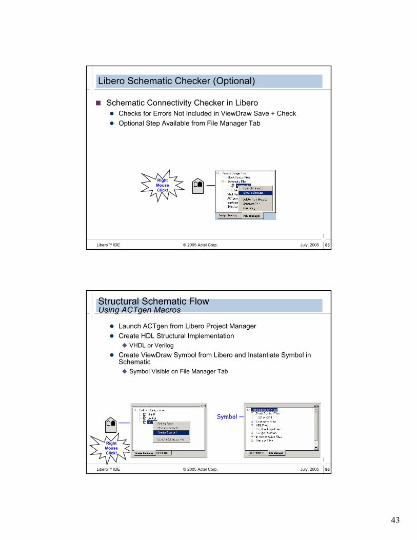
Libero Schematic Checker (Optional)
� Schematic Connectivity Checker in Libero
� Checks for Errors Not Included in ViewDraw Save + Check
� Optional Step Available from File Manager Tab
Right
Mouse
Click!
© 2005 Actel Corp. 86Libero™ IDE July, 2005
Structural Schematic FlowUsing ACTgen Macros
� Launch ACTgen from Libero Project Manager
� Create HDL Structural Implementation
� VHDL or Verilog
� Create ViewDraw Symbol from Libero and Instantiate Symbol in Schematic
� Symbol Visible on File Manager Tab
Right
Mouse
Click!
Symbol

44
Mixed-Mode Designs
© 2005 Actel Corp. 88Libero™ IDE July, 2005
Mixed-Mode Design Flow
Place & Route
Synthesis
Programming
Simulation Post-Synthesis Simulation
Post-P&R Simulation
Design Capture

45
© 2005 Actel Corp. 89Libero™ IDE July, 2005
Design Capture
Place & Route
Synthesis
Programming
Simulation Post-Synthesis Simulation
Post-P&R Simulation
Design Capture
© 2005 Actel Corp. 90Libero™ IDE July, 2005
Mixed Mode Design Entry
� Mixed Mode => RTL Blocks within Schematic
� HDL Blocks Can Be Structural or Behavioral RTL
� RTL Blocks Can Be VHDL or Verilog (But Not Both)
� Top Level Must Be Schematic
� Procedure
� Create HDL Blocks
� RTL Blocks - Use HDL Editor or Import Existing Design Files
� Structural Blocks - Use HDL Editor or ACTgen
� Create ViewDraw Symbols for HDL Blocks
� Done Automatically from Libero Design Flow Manager
� Instantiate Blocks in Schematics and Make Interconnects
� Use Hierarchical Connectors from ViewDraw “built-in” Library for HDL Ports in Schematic
46
© 2005 Actel Corp. 91Libero™ IDE July, 2005
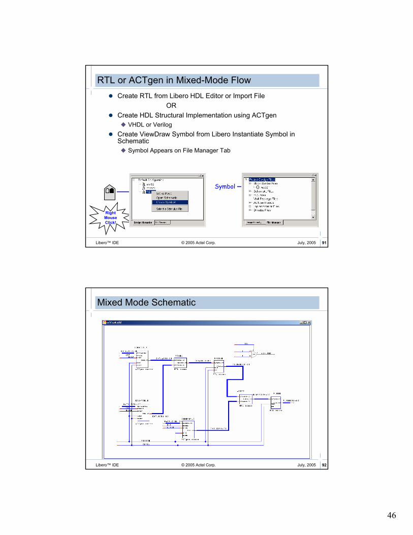
RTL or ACTgen in Mixed-Mode Flow
� Create RTL from Libero HDL Editor or Import File
OR
� Create HDL Structural Implementation using ACTgen
� VHDL or Verilog
� Create ViewDraw Symbol from Libero Instantiate Symbol in Schematic
� Symbol Appears on File Manager Tab
Right
Mouse
Click!
Symbol
© 2005 Actel Corp. 92Libero™ IDE July, 2005
Mixed Mode Schematic

47
© 2005 Actel Corp. 93Libero™ IDE July, 2005
Synthesize
� Optional for Pure Schematic or Structural Schematic Flows
� All HDL Blocks Are Structural VHDL or Verilog (e.g., ACTgen Blocks)
� Required for Mixed-mode Designs
� Designs Containing RTL Blocks
� Libero Launches Synplicity to Insert Pads and Optimize Design
� Hierarchical Connectors Must Be Used
� Structural Schematics with All Pads Instantiated Can Go Directly to Designer Tool
Synthesize
HDL Designs

48
© 2005 Actel Corp. 95Libero™ IDE July, 2005
HDL Design Flow
Place & Route
Synthesis
Programming
Simulation Post-Synthesis Simulation
Post-P&R Simulation
Design Capture
© 2005 Actel Corp. 96Libero™ IDE July, 2005
Design Capture
Design Capture
Simulation Synthesis
Programming
Post-Synthesis Simulation
Post-P&R Simulation
Place & Route

49
© 2005 Actel Corp. 97Libero™ IDE July, 2005
Creating New HDL Macros
© 2005 Actel Corp. 98Libero™ IDE July, 2005
HDL Editor

50
© 2005 Actel Corp. 99Libero™ IDE July, 2005
HDL EditorBlock Comments
� Comment and Uncomment Command Allows Users to Comment or Uncomment Sections of VHDL or Verilog Code
© 2005 Actel Corp. 100Libero™ IDE July, 2005
HDL EditorDetect Changes
� If File Is Open in Libero HDL Editor and Modified by another Text Editor, Warning Is Issued
Warning message in Libero log window

51
© 2005 Actel Corp. 101Libero™ IDE July, 2005
Libero HDL Syntax Checker
� HDL Syntax Checker Available from File Manager Tab
� Checks for Errors in HDL Blocks
� Errors Indicated in Libero Log Window
� Optional Step
Right
Mouse
Click!
© 2005 Actel Corp. 102Libero™ IDE July, 2005
Project Manager with Saved Files...
VHDL file

52
© 2005 Actel Corp. 103Libero™ IDE July, 2005
Functional Simulation
Post-Synthesis Simulation
Post-P&R Simulation
Design Capture
Synthesis
Place & Route
Programming
Simulation
© 2005 Actel Corp. 104Libero™ IDE July, 2005
Simulation Flow
� For Each Block You Want to Simulate . . .
Export Testbench
Invoke simulator
Compile and Run
the simulation
Generate stimulus View Waveforms
Associate Stimulus

53
© 2005 Actel Corp. 105Libero™ IDE July, 2005
Invoking WaveFormer Lite
or
Double
Click!
Right
Mouse
Click!
© 2005 Actel Corp. 106Libero™ IDE July, 2005
WaveFormer Lite Features
� Allows Convenient Test Stimulus Specification via GUI
� User Specifies Stimulus by Drawing Waveforms
� Supports Copy / Paste / Append Operations
� Significantly Reduces TestBench Creation Time
� Automatically Converts Graphical Stimulus Files into HDL TestBenches
� Can Generate:
� VHDL Testbench (*.vhd)
� Verilog Testbench (*.v)
� Users Can Annotate Waveform For Design Documentation

54
© 2005 Actel Corp. 107Libero™ IDE July, 2005
Signal level controls Zoom controls
Bus value controls
Drawing the Stimulus
� WaveFormer Lite Diagram Window
inputs
Cursorlocation
© 2005 Actel Corp. 108Libero™ IDE July, 2005
Creating Clocks
Double
Click!
Clock frequency
Clock name
Clock duty cycle
Start highor low

55
© 2005 Actel Corp. 109Libero™ IDE July, 2005
Creating Clocks
© 2005 Actel Corp. 110Libero™ IDE July, 2005
Drawing Signals
Align courser and click!Use zoom controls to make viewing easier
State button toggles automatically
Select “low” state button

56
© 2005 Actel Corp. 111Libero™ IDE July, 2005
Drawing SignalsEdge Placement
Double click at end of signalEnter time for edge placement
© 2005 Actel Corp. 112Libero™ IDE July, 2005
Editing Signals

57
© 2005 Actel Corp. 113Libero™ IDE July, 2005
Drawing Busses
Double
Click!
Double click “VAL” state button
© 2005 Actel Corp. 114Libero™ IDE July, 2005
Editing SignalsAppending and Inserting
Copy of waveformis inserted!

58
© 2005 Actel Corp. 115Libero™ IDE July, 2005
Copying to a Different Signal
Copy of waveformis inserted!
� Signal Can Be Copied
© 2005 Actel Corp. 116Libero™ IDE July, 2005
Reactive Test Bench:Stimulus and Expected Response
� Draw stimulus waveforms on the input ports of the model under test.
� Draw expected response waveforms on the output ports of the model under test

59
© 2005 Actel Corp. 117Libero™ IDE July, 2005
Reactive Test Bench:Samples
� Samples Verify MUT Output
� Sample constructs can monitor and perform actions based on the data sampled
� Sample can work at a single point or over a windowed area
� Sample can perform relative to the beginning of the transaction or relative to another event in the diagram.
© 2005 Actel Corp. 118Libero™ IDE July, 2005
Reactive Test Bench:Control & Looping
� Markers used for Control & Looping Sections of Transactions
� Specify the end of the transaction
� Create loops using for, while, and repeat loop markers
� Insert HDL code

60
© 2005 Actel Corp. 119Libero™ IDE July, 2005
Reactive Test Bench:Variables
� Variables Parameterize State Values
� Variables can drive values on stimulus waveforms
� Variables can store values on expected waveforms
� Waveform states can be expressed as conditional expressions using variables
© 2005 Actel Corp. 120Libero™ IDE July, 2005
Reactive Test Bench:Delays
� Delays Parameterize Time Values
� Delays represent the time between two edges in the diagram
� Specify min and max values
� Delay values can be time or cycle-based
� Conditionally control when edges occur
61
© 2005 Actel Corp. 121Libero™ IDE July, 2005
Reactive Test Bench:Help Resources
� Online Manual: Under the Help menu choose Reactive Test Bench Generation to open the help
� PDF Manual: Under the SynaptiCAD install directory there is a subdirectory called Help with Reactive_test bench_Generation_Option.pdf
� SynaptiCAD’s website: www.syncad.com
© 2005 Actel Corp. 122Libero™ IDE July, 2005
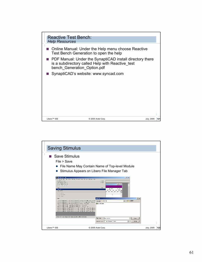
Saving Stimulus
� Save Stimulus
File > Save
� File Name May Contain Name of Top-level Module
� Stimulus Appears on Libero File Manager Tab
62
© 2005 Actel Corp. 123Libero™ IDE July, 2005
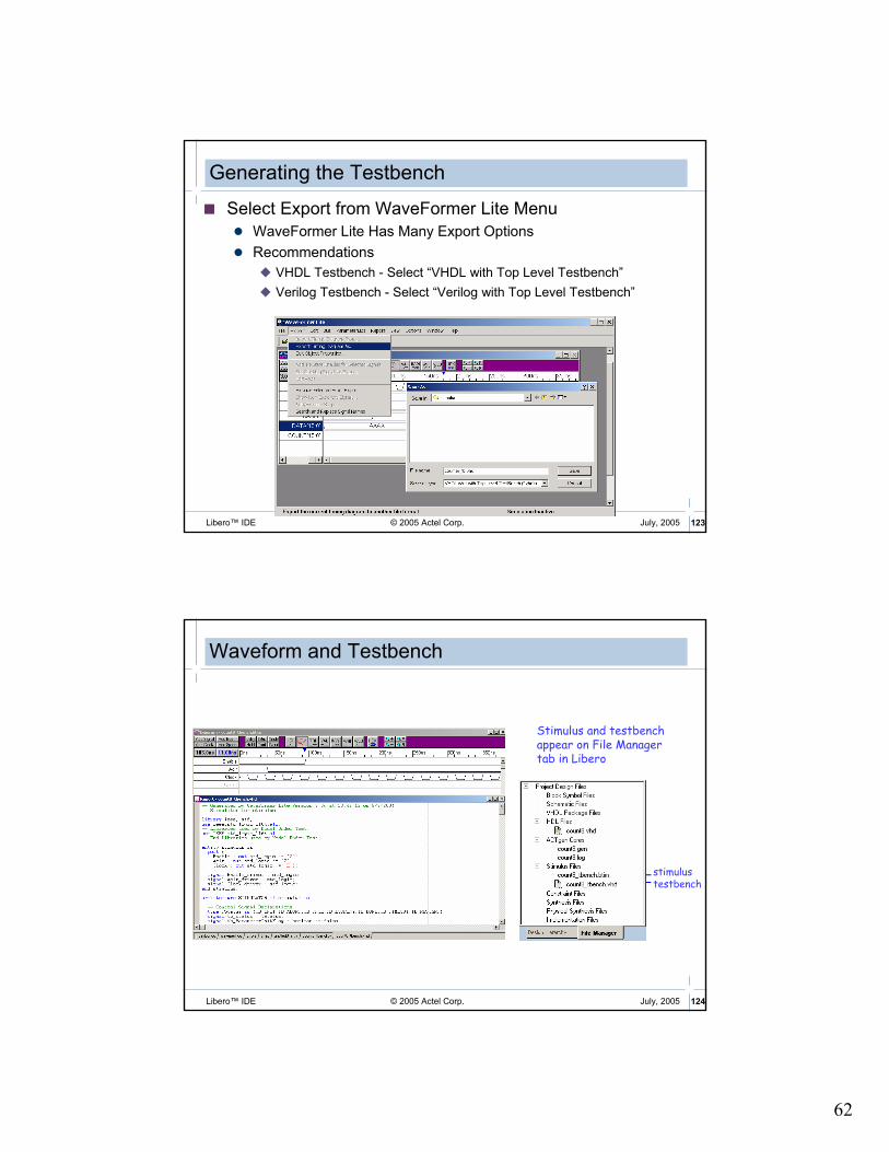
Generating the Testbench
� Select Export from WaveFormer Lite Menu
� WaveFormer Lite Has Many Export Options
� Recommendations
� VHDL Testbench - Select “VHDL with Top Level Testbench”
� Verilog Testbench - Select “Verilog with Top Level Testbench”
© 2005 Actel Corp. 124Libero™ IDE July, 2005
Waveform and Testbench
stimulustestbench
Stimulus and testbench appear on File Manager tab in Libero

63
© 2005 Actel Corp. 125Libero™ IDE July, 2005
ModelSim AE
© 2005 Actel Corp. 126Libero™ IDE July, 2005
ModelSim AE
� Same Functionality as ModelSim PE� Windows 98, Win NT, Win 2000 or Win XP
� Node-Locked
� VHDL or Verilog
� Reduced Performance
� No Co-simulation (VHDL and Verilog) Capability
� Limited to Simulation of Actel’s Gate-level Libraries
� Supported through Actel

64
© 2005 Actel Corp. 127Libero™ IDE July, 2005
ModelSim User Interface
TCL/TK User Interface
TCL Scripting
Source Level Debug
Debug Windows
Waveform Display
Data linked to cursor
© 2005 Actel Corp. 128Libero™ IDE July, 2005
ModelSim Windows
� There Are Nine Windows
� Main, Structure, Source, Signals, Process, Variables, Dataflow,Wave, & List Windows
� Additional Window Features
� Drag & Drop
� HDL Items Can Be Dragged from Dataflow, List, Signals, Source, Structure, Variables, and Wave Windows …
� … And Dropped into either List or Wave Window
� Automatic Window Updating

65
© 2005 Actel Corp. 129Libero™ IDE July, 2005
ModelSim Main Window
Menu Bar Tool Bar (Break, Run, Cont, Step, and Step Over)
Status Bar (current time, delta time step, environment)
TCL InterpreterModelSim> prompt before design is loaded.VSIM> prompt is displayed after design is loaded
Design Hierarchy
© 2005 Actel Corp. 130Libero™ IDE July, 2005
Structure Window
� Hierarchical View of Design Structure
� VHDL (Squares) – Package, Component Instantiation, Generate and Block Statements
� Verilog (Circles) – Module Instantiation, Named fork, Named begin, task, and function
� Instantiation Label, entity/module, architecture
� Becomes Current Region for Source and Signals Window, Updates Process and Variables Window

66
© 2005 Actel Corp. 131Libero™ IDE July, 2005
Signals Window
� Follows Structure Window� Shows Names and Values of HDL Items in Current Region of
Structure Window
� Items Can Be Sorted in Ascending, Descending or Declaration Order
� Hierarchy (+) Expandable� VHDL Items - Signals
� Verilog Items - Nets, Register Variables
� Named Events
� “Drag & Drop”� Wave & List windows
� Force Apply Stimulus
� Filter Signal Types (input,output etc)
� Find HDL Items
© 2005 Actel Corp. 132Libero™ IDE July, 2005
Source Window
� Selected from Structure Window
� Color-coded Comments, Keywords, Strings, Numbers, Executable Lines, Identifiers, System Tasks, Text
� Full Edit Capability
� Save, Compile and Restart
� Drag and Drop
� Describe
� Examine

67
© 2005 Actel Corp. 133Libero™ IDE July, 2005
Wave Window
Multiple PanesDrag & Drop
Multiple Cursors
Zooming
Cursor
MeasurementsSimulation Control Item formatting
Virtuals
© 2005 Actel Corp. 134Libero™ IDE July, 2005
Creating Busses in Wave Window
� Scalar Signals Can Be Combined into Vectors
68
© 2005 Actel Corp. 135Libero™ IDE July, 2005
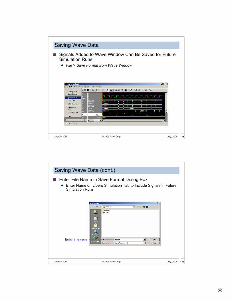
Saving Wave Data
� Signals Added to Wave Window Can Be Saved for Future Simulation Runs
� File > Save Format from Wave Window
© 2005 Actel Corp. 136Libero™ IDE July, 2005
Saving Wave Data (cont.)
� Enter File Name in Save Format Dialog Box
� Enter Name on Libero Simulation Tab to Include Signals in FutureSimulation Runs
Enter file name

69
© 2005 Actel Corp. 137Libero™ IDE July, 2005
Wave Log Files (Datasets)
� Wave window waveforms can be saved as a Wave Log File (.wlf) for importing into other simulations.
� File > Save Dataset in Wave window
© 2005 Actel Corp. 138Libero™ IDE July, 2005
Wave Log Files (cont.)
� Enter file name in Save Dataset dialog box
Enter name

70
© 2005 Actel Corp. 139Libero™ IDE July, 2005
Opening Datasets
� Any number of Datasets can be opened for viewing or comparing to the current simulation
� File > Open > Dataset (Main Window)
� File > Open Dataset (Wave Window)
© 2005 Actel Corp. 140Libero™ IDE July, 2005
Opening Datasets (cont.)
Click to browse for dataset
Select file and click open

71
© 2005 Actel Corp. 141Libero™ IDE July, 2005
Opening Datasets (cont.)
� Open dataset is displayed on a new tab in the ModelSim Main Window workspace.
Tab for dataset “gold”
© 2005 Actel Corp. 142Libero™ IDE July, 2005
Adding Datasets to Wave Window
� Dataset signals can be added to the Wave window
� Select appropriate tab in workspace then use Structure and Signals windows
� Visually compare simulation results

72
© 2005 Actel Corp. 143Libero™ IDE July, 2005
Signals from dataset “gold”
Adding Datasets to Wave Window (cont.)
© 2005 Actel Corp. 144Libero™ IDE July, 2005
Managing Datasets
� Multiple Datasets can be managed with the Dataset browser
� View > Datasets from Main Window
� Options:
� Open, Close, Make Active, Rename

73
© 2005 Actel Corp. 145Libero™ IDE July, 2005
Process Window
� View Active
� Displays All Processes Scheduled to Run during Current Simulation Cycle
� View In Region
� Displays any Processes that Exist in Region Selected in Structure Window
� Process State
� Ready, Wait, Done
� Window Update
� Show Region in Structure Window
� Points to Source Lines
� Shows Variables in Process
� Displays Process in Dataflow
© 2005 Actel Corp. 146Libero™ IDE July, 2005
Variables Window
� Lists Names of HDL Items in Current Process� VHDL - Constants, Generics and Variables
� Verilog - Register Variables
� Tree Hierarchy - (+) Expandable, (-) Expanded
� Sort� Ascending, Descending
� Declaration Order
� Change Value of Selected HDL Item
� Find� Forward or Reverse Search
� Drag & Drop� Wave or List Windows or Log File

74
© 2005 Actel Corp. 147Libero™ IDE July, 2005
DataFlow Window
Explore physical connectivity of design
� Displays processes, signals, nets and registers
� Links to Main, Process, Signals, Wave and Source windows
� Find feature allows searching for signal, net or register names
© 2005 Actel Corp. 148Libero™ IDE July, 2005
Dataflow WindowModelSim AE Simulator
� The ModelSim AE simulator has a limited Dataflow functionality
� Only one process and it’s attached signals or one signal and it’s attached processes are displayed
Zoomcontrol
Display net drivers or readers

75
© 2005 Actel Corp. 149Libero™ IDE July, 2005
List Window
� Simulation Results in Tabular Format
� VHDL - Signals and Process Variables
� Verilog - Nets and Registers
� “Drag & Drop”
� Find Function
� Trigger / Strobe Properties
� Write List
� Tabular
� Event
� TSSI
� Markers - Add, Delete or Goto
© 2005 Actel Corp. 150Libero™ IDE July, 2005
Saving Tabular Output
Drag & Drop!

76
© 2005 Actel Corp. 151Libero™ IDE July, 2005
Advancing Simulation Time
� Three Methods
� At VSIM prompt:
� VSIM 12> run 100 ms
� In Main Window Tool Bar:
� In Wave Window Tool Bar:
Run Length Continue Run Break Step Over
Run Run -all
Continue Run Break
Restart Run Run -all Step
© 2005 Actel Corp. 152Libero™ IDE July, 2005
Re-running Simulation
� Restart to Zero
� Force Restart at VSIM Prompt
� VSIM 12> restart –f
� In Main Window Run > Restart or Restart Button
� Displays Restart Dialog
� Keep Current
� Listed Signals
� Waved Signals
� Breakpoints
� Logged Signals
� Virtual Signals

77
© 2005 Actel Corp. 153Libero™ IDE July, 2005
ModelSim Macro Files
� ModelSim Commands Can Be Saved in Macro File
� The ‘do’ Command Executes Commands
� Macro File Can Have any Name and Extension
Syntax:
do<filename> [<parameter_value>]
Example:
do run.do
� This Command Executes File run.do
vlib presynth
vmap presynth ./presynth
vcom -93 -work presynth D:/Actelprj/count32/hdl/count32.vhd
vcom -93 -work presynth D:/Actelprj/count32/stimulus/count32.vhd
vsim presynth.testbench
add wave /testbench/*
run 1000ns
© 2005 Actel Corp. 154Libero™ IDE July, 2005
Libero Simulation Options
� Simulation Options Can Be Set from Simulation Tab under Options
� Results Saved in run.do File
Include Do file allows Libero to include user-defined script. User can enter name of script file
Specify simulation run time
Select min, typ, max simulation conditions for post-layout simulation
Default resolution based on family choice
1ps for 500K, APA, 54SXA, AX
1ns for all other families
Use Automatic Do File allows Libero to automatically set up the simulation for the user

78
© 2005 Actel Corp. 155Libero™ IDE July, 2005
Invoking ModelSimPre- or Post-Synthesis
� Click “Simulation” Design Flow Window or …
Right
Mouse
Click!
Double
Click!
© 2005 Actel Corp. 156Libero™ IDE July, 2005
Associating Stimulus
Right
Mouse
Click!

79
© 2005 Actel Corp. 157Libero™ IDE July, 2005
Hierarchical Testbench Support
� Libero Allows Users to Specify List of Stimulus Files for Simulation
� No Stimulus File Selected by Default
� Libero Remembers Stimulus Association for Any Block
© 2005 Actel Corp. 158Libero™ IDE July, 2005
Pre-Synthesis Simulation
� ModelSim Automatically Compiles Design and Runs Simulation for 1 µµµµS
� (External) Signals from Testbench Automatically Added to Wave Window
� Additional (Internal) Signals Can Be Added by User

80
© 2005 Actel Corp. 159Libero™ IDE July, 2005
Libero Simulation files on HDD
© 2005 Actel Corp. 160Libero™ IDE July, 2005
Simulating DesignsSummary
� Capture Design
� Generate RTL Netlist (VHDL or Verilog)
OR
� Create Schematic
� May Include RTL blocks
� Structural VHDL or Verilog Netlist Automatically Created before Simulation
� Create Testbench
� Use WaveFormer Lite, or Text Editor
� Associate Stimulus
� Run Pre-Synthesis Simulation

81
© 2005 Actel Corp. 161Libero™ IDE July, 2005
Synthesis
Simulation Post-Synthesis Simulation
Post-P&R Simulation
Design Capture
Place & Route
Programming
Synthesis
© 2005 Actel Corp. 162Libero™ IDE July, 2005
Invoking Synplicity
� Click “Synthesis” in Design Flow Window or ..
or
Right
Mouse
Click!
Double
Click!

82
© 2005 Actel Corp. 163Libero™ IDE July, 2005
Synplify Interface
Global synthesisconstraints
Change target and result file
Add constraint files or VHDL packages
Libero automatically lists files lowest levels first, top last
© 2005 Actel Corp. 164Libero™ IDE July, 2005
Result File
� Synplicity Produces an EDIF Netlist
� <design>.edn
� Libero Automatically Produces Structural VHDL or Verilog Netlist
� <design>.vhd or <design>.v
� Results Appear on File Manager Tab under Synthesis Files

83
© 2005 Actel Corp. 165Libero™ IDE July, 2005
Setting the Target Options
By default, Synplify will insert Actel I/O macros on all the HDL I/O ports.When synthesizing lower-level blocks, this must be disabled.
High fanout = slow, small designsLow fanout = fast, large designsUse defaults for first pass
© 2005 Actel Corp. 166Libero™ IDE July, 2005
Global Constraints
� Frequency
� Symbolic FSM Compiler
� Configure HDL Compiler
� Resource Sharing

84
© 2005 Actel Corp. 167Libero™ IDE July, 2005
Frequency
Global clock frequency -0MHz means optimize for area
© 2005 Actel Corp. 168Libero™ IDE July, 2005
Symbolic FSM Compiler
When checked, it selects proper encoding for all state machines.
Encoding method can be set on individual state machines with syn_encoding directive in the HDL code

85
© 2005 Actel Corp. 169Libero™ IDE July, 2005
State Machine Encoding (VHDL)
Options > Configure VHDL Compiler
Sets the default encoding style for enumerated types
Override encoding style on an individual basis using syn_encoding directive in constraint editor or the HDL source code
# of states default encoding
1 - 4 sequential
5 - 24 one-hot
> 24 gray
© 2005 Actel Corp. 170Libero™ IDE July, 2005
B
A
D
C
Y
+
+
S
Without resource sharing With resource sharing
S
+
C
A
D
B
Y
Resource Sharing
� When enabled, Synplify performs automatic sharing of operator resources, including adders, subtractors, incrementers, and decrementers.
if (s = ‘0’) then
Y <= A + B;
else
Y <= C + D;
end if;
if (s = ‘0’) then
Y <= A + B;
else
Y <= C + D;
end if;

86
© 2005 Actel Corp. 171Libero™ IDE July, 2005
Performing Synthesis
Compile only or check syntax
© 2005 Actel Corp. 172Libero™ IDE July, 2005
View Log
� Synplify Log contains Plenty of Valuable Information:!
� Warnings and Errors
� Double-click and Jump to Code!
� Fanout Limit
� Extraction Information (Found Counter, FSM, Adder, etc.)
� Net Loading
� Logic Buffering and Replication Information
� Resource Usage
� Critical Path Timing Analysis

87
© 2005 Actel Corp. 173Libero™ IDE July, 2005
Reading the Log File: Errors
DoubleClick!
© 2005 Actel Corp. 174Libero™ IDE July, 2005
Constraint Editor
� Synplify facilitates constraint entry with a spreadsheet-like constraint editor.
� File->New
� Select Constraint File (Spreadsheet)
Select Files of type Constraint Files
� Press OK
� Extremely easy to use

88
© 2005 Actel Corp. 175Libero™ IDE July, 2005
Constraint Editor (Cont.)
� Constraint Editor supports a Drag and Drop interface.
� There are sheets for entering:
� Clock Frequency or Period
� Clock to Clock timing
� Input/Output Constraints
� Registers Constraints
� Multi-Cycle Paths
� False Paths
� Attributes
Synplicity Directives and Attributes
89
© 2005 Actel Corp. 177Libero™ IDE July, 2005
Synplicity Directives and Attributes
� Let You Direct Analysis, Optimization, and Mapping of Design during Synthesis
� Attributes Control Mapping Optimizations
� Attributes Can Be Entered in either .sdc Constraint File or HDL Source Code
� Synplify Supports Limited Number of Attributes that Can Be Entered in Attribute Pane
� Most Attributes Are Entered in your VHDL or Verilog Code
� Directives Control Compiler Optimizations
� Directives Must Be Entered in HDL Source Code
© 2005 Actel Corp. 178Libero™ IDE July, 2005
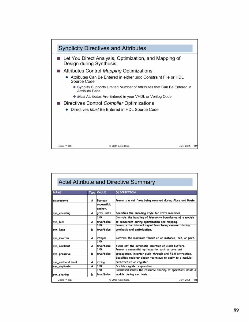
Actel Attribute and Directive Summary
NAME Type VALUE DESCRIPTION
alspreserve A Boolean Prevents a net from being removed during Place and Route
syn_encoding A
sequential,
onehot,
gray, safe Specifies the encoding style for state machines.
syn_hier A
1/0
true/false
Controls the handling of hierarchy boundaries of a module
or component during optimization and mapping.
syn_keep D
1/0
true/false
Prevents the internal signal from being removed during
synthesis and optimization.
syn_maxfan A integer Controls the maximum fanout of an instance, net, or port.
syn_noclkbuf A
1/0
true/false Turns off the automatic insertion of clock buffers.
syn_preserve D
1/0
true/false
Prevents sequential optimization such as constant
propagation, inverter push-through and FSM extraction.
syn_radhard level A string
Specifies register design technique to apply to a module,
architecture or register
syn_replicate A 1/0 Disable register replication
syn_sharing D
1/0
true/false
Enables/disables the resource sharing of operators inside a
module during synthesis.

90
© 2005 Actel Corp. 179Libero™ IDE July, 2005
alspreserveActel-Specific Attribute
� Keeps Net from Being Collapsed in Designer (Back-end) Tools� Must also Add syn_keep to Ensure Synplicity Retains Net
� Synplicity Adds alspreserve Attribute to EDIF Netlist
© 2005 Actel Corp. 180Libero™ IDE July, 2005
alspreserveSyntax
� Verilog Syntaxobject /* synthesis alspreserve = 1 */ ;
� Example:
� VHDL Syntaxattribute alspreserve of object : signal is true ;
� Example:
module foo ( in, out);
input [6:0] in; output out; wire out;
wire or_out1 /* synthesis syn_keep=1 alspreserve=1 */;
wire and_out1; wire and_out2;
wire and_out3 /* synthesis syn_keep=1 alspreserve=1 */;
architecture comb of foo is
signal and_out1, and_out2, and_out3, or_out1 : std_logic;
attribute syn_keep of and_out3 : signal is true;
attribute syn_keep of or_out1 : signal is true;
attribute alspreserve: boolean;
attribute alspreserve of and_out3 :signal is true;
attribute alspreserve of or_out1 : signal is true;

91
© 2005 Actel Corp. 181Libero™ IDE July, 2005
syn_radhardlevelExample (cont.)
SCOPE attribute tab:
Source files:
Add to infer C-module flip-flops
use C-module flip-flop for qA
© 2005 Actel Corp. 182Libero™ IDE July, 2005
syn_encodingAttribute
� Sets Encoding Style for State Machines
� Overrides Default Style
� Default Style - Compiler Selects Encoding Style Based on Number of States as Follows:
� 1 - 4 States: Sequential
� 5 - 24 States: One-hot
� > 24 States: Gray
� syn_encoding Can Have the Following Values:
� onehot
� gray
� sequential
� safe

92
© 2005 Actel Corp. 183Libero™ IDE July, 2005
syn_maxfanAttribute
� Controls Maximum Fanout of Instance, Net, or Port
� Limit Specified by this Attribute May Be Treated as Hard or Soft Depending on Where It Was Specified
� Soft Limit May Not Be Honored if it Degrades Performance
� You Can Apply syn_maxfan Attribute to Module, Register, Instance, Port, or Net
� For ProASIC and APA Designs Only – You Can also Apply to Module or Entity
© 2005 Actel Corp. 184Libero™ IDE July, 2005
syn_maxfanUsage
� SCOPE Constraint Editor Usage
� SDC File Syntaxdefine_attribute { object } syn_maxfan { integer
}
� Example – Limit Fanout for Signal clk to 200:
. . .define_attribute {clk} syn_maxfan {200}
. . .

93
© 2005 Actel Corp. 185Libero™ IDE July, 2005
� Verilog Syntaxobject /* synthesis syn_maxfan = "value" */ ;
� Example:
� VHDL Syntax
attribute syn_maxfan of object : object_type is "value"
;
� Example:
module test (registered_data_out, clock, data_in);
output [31:0] registered_data_out; input clock;
input [31:0] data_in /* synthesis syn_maxfan=1000 */;
reg [31:0] registered_data_out /* synthesis syn_maxfan=1000 */;
// Other code
entity test is
port(clock : in bit;
data_in : in bit_vector(31 downto 0);
registered_data_out: out bit_vector(31 downto 0))
attribute syn_maxfan : integer;
attribute syn_maxfan of data_in : signal is 1000;
-- Other code
syn_maxfanSyntax
© 2005 Actel Corp. 186Libero™ IDE July, 2005
syn_replicateAttribute
� Prevents Replication of Register� assign syn_replicate = 0 Turns Off Register Replication
� Cannot Force Tool to Replicate
� Works along with max_fanout Value
� Only Supported on Individual Register
� When Will Synplify Replicate or Buffer?
� Generally Flip-flops Are Replicated to Achieve Fan-out Control
� For Combinatorial Cells, Buffers Are Added

94
© 2005 Actel Corp. 187Libero™ IDE July, 2005
syn_replicateUsage
� SCOPE Constraint Editor Usage
� SDC File Syntaxdefine_global_attribute syn_replicate = { 1 | 0 }
Example - Disables All Replication in Design:
1 enables replication0 disables replication
. . .define_global_attribute syn_replicate {0}
. . .
© 2005 Actel Corp. 188Libero™ IDE July, 2005
� Verilog Syntaxobject /* synthesis syn_replicate = 1 | 0 */;
� Example:
module norep (Reset, Clk, Drive, OK, ADPad, IPad, ADOut);
. . .reg [31:0] IPad;
reg DriveA /* synthesis syn_replicate = 0 */;
assign ADPad = DriveA ? ADOut : 32'bz;
always @(posedge Clk or negedge Reset)
if (!Reset) begin
DriveA <= 0;
IPad <= 0; end
else begin
DriveA <= Drive & OK;
IPad <= ADPad; end
endmodule
1 enables replication0 disables replication
syn_replicateUsage (cont.)

95
© 2005 Actel Corp. 189Libero™ IDE July, 2005
� VHDL Syntaxattribute syn_replicate of object : object_type is
true | false ;
� Example:
entity norep is port (
Reset : in std_logic;
Clk : in std_logic;
Drive : in std_logic;
OK : in std_logic;
ADPad : inout std_logic_vector (31 downto 0);
IPad : out std_logic_vector (31 downto 0);
ADOut : in std_logic_vector (31 downto 0));
end norep;
architecture archnorep of norep is
signal DriveA : std_logic;
attribute syn_replicate : boolean;
attribute syn_replicate of DriveA : signal is false;
begin
-- Other code
syn_replicateUsage (cont.)
© 2005 Actel Corp. 190Libero™ IDE July, 2005
syn_sharingDirective
� Enables/Disables Resource Sharing of Operators inside Module during Synthesis
� By Default, Directive Is Enabled (Value 1 for Verilog, true for VHDL).
� If Resource Sharing Check Box in Project View is Disabled, You Can Still Enable Resource Sharing Using syn_sharingDirective

96
© 2005 Actel Corp. 191Libero™ IDE July, 2005
� Verilog Syntaxobject /* synthesis syn_sharing = 1 | 0 */ ;
� Example:
� VHDL Syntaxattribute syn_sharing of object : object_type is " true | false";
object can be architecture name
� Example:
module my_design(out,in,clk_in) /* synthesis syn_sharing=0 */;
// Other code
entity alu is
port ( a, b : in std_logic_vector (7 downto 0);
. . . );
end alu;
architecture behave of alu is
-- Turn on resource sharing for the architecture.
attribute syn_sharing of behave : architecture is "true";
begin
-- Other code
syn_sharingUsage
© 2005 Actel Corp. 192Libero™ IDE July, 2005
RetimingSynplify Pro
� Retiming Is Feature in Synplify Pro ver 7.5.1
� Helps Improve Performance of Sequential Circuits
� Moves Registers across Combinatorial Gates
� Also Called Register Balancing
� Global Option – Can Be Turned On/Off in GUI
� Cannot Have this Option on per-Block Basis because it Optimizes Whole Design
� Advantages
� Improves Design Performance
� No Need to Modify RTL Code
� # of Register Cycles Remains the Same
� Impact
� May Result in Higher Utilization
� May Increase Difficulty in Routing
� Some Designs May Degrade in Performance!
Synplify 7.5.1 Pro GUI

97
© 2005 Actel Corp. 193Libero™ IDE July, 2005
Retiming (cont.)
� Retiming Moves Registers across Design to Achieve the Best Possible fmax
� Before Retiming
� After Retiming
Performance: 67MHz
Limited by 15ns
Performance: 83MHz
Limited by 12ns
Reg Reg15ns 5nsReg
Reg Reg12ns 8nsReg
© 2005 Actel Corp. 194Libero™ IDE July, 2005
Synplify and Synplify PRO for Actel
� Synplify for Actel Is Equivalent to Synplicity's Synplify Product.
� Limited to Actel Products Only
� Does Not include RAM Inferencing
� Included in All Libero Products
� Synplify Pro AE has additional features beyond Synplify AE and requires a separate license from Actel
� Limited to Actel products only
98
© 2005 Actel Corp. 195Libero™ IDE July, 2005
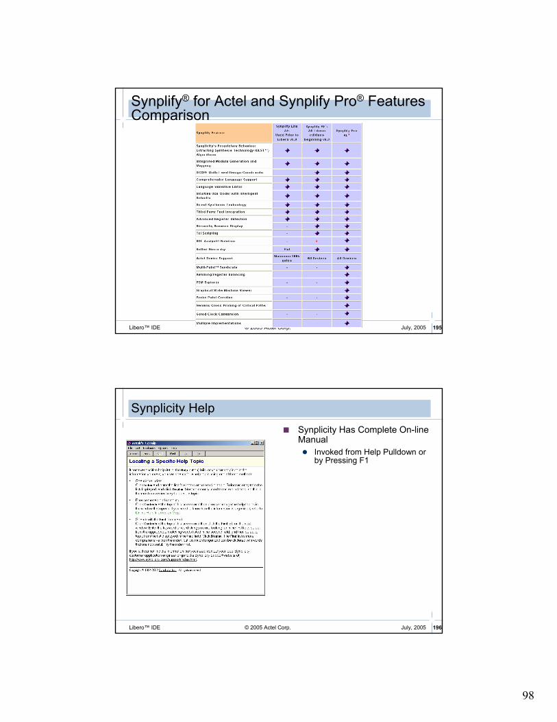
Synplify® for Actel and Synplify Pro® Features Comparison
© 2005 Actel Corp. 196Libero™ IDE July, 2005
Synplicity Help
� Synplicity Has Complete On-line Manual
� Invoked from Help Pulldown or by Pressing F1

99
© 2005 Actel Corp. 197Libero™ IDE July, 2005
Post-Synthesis Simulation
Simulation
Post-P&R Simulation
Design Capture
Place & Route
Programming
Post-Synthesis SimulationSynthesis
© 2005 Actel Corp. 198Libero™ IDE July, 2005
Post-Synthesis Simulation
� Steps:
� Synthesize Design with Synplicity
� Generate EDIF Netlist from Synplicity
� Libero Automatically Creates Structural VHDL or Verilog Netlist
� Run Post-synthesis Simulation on Structural Netlist

100
© 2005 Actel Corp. 199Libero™ IDE July, 2005
Post-Synthesis Simulation
� Click on “Simulation” in Design Flow window or…
or
Right
Mouse
Click!
Double
Click!
© 2005 Actel Corp. 200Libero™ IDE July, 2005
Post-Synthesis Simulation
� ModelSim automatically compiles structural netlist exported from Designer
� Runs simulation for 1 uS
� Structural library mapping handled by Libero
� Pre-compiled libraries do not require compiling prior to simulation
101
© 2005 Actel Corp. 201Libero™ IDE July, 2005
Place and Route
Post-Synthesis Simulation
Post-P&R Simulation
Design Capture
Synthesis
Programming
Place & Route
Simulation
© 2005 Actel Corp. 202Libero™ IDE July, 2005
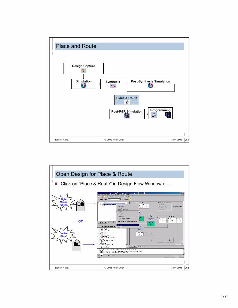
Open Design for Place & Route
� Click on “Place & Route” in Design Flow Window or…
or
Right
Mouse
Click!
Double
Click!

102
© 2005 Actel Corp. 203Libero™ IDE July, 2005
Designer Interface
� Designer Provides Graphical Flow Manager to Lead Designer through Design Flow
� Completed Tasks Highlighted
� Design Flow Steps Listed at Top
� User Tools Grouped Below
Designer Error Manager Tabs (same as Libero)
© 2005 Actel Corp. 204Libero™ IDE July, 2005
Designer TCL Script Support
Industry-standard Language
� Tool Command Language
� Launch Multiple Tools from Single Script
� Launch Multiple Design Runs
Simulator
Synthesis
DesignerTCLscript

103
© 2005 Actel Corp. 205Libero™ IDE July, 2005
Running Scripts within Designer
� In File Menu, Click Execute Script File
� Displays Execute Script Dialog Box
Enter name of script file
Enter arguments to be passedto script file
Click Run to execute script
Tcl Scripts can be Executed from the Command Line:Example:
d:\Libero\Designer\bin\designer script:my_script
© 2005 Actel Corp. 206Libero™ IDE July, 2005
Recording Scripts
� Designer Can Export Tcl Script File that Contains Commands Executed in Current Session
� Exported Tcl Script can be used to …
� … re-Execute Same Commands Interactively or in Batch
� … Become More Familiar with Tcl Syntax

104
© 2005 Actel Corp. 207Libero™ IDE July, 2005
Importing Source Files
File Type Extension
EDIF *.ed*
Verilog *.vVHDL *.vhd
Actel ADL Netlist *.adlCriticality *.crt
ProASIC Constraint File *.gcfPhysical Design Constraint File *.pdc
Multiple files can be imported at the same time
Netlist import is done automatically by Libero
Import File types:
© 2005 Actel Corp. 208Libero™ IDE July, 2005
Importing Auxiliary Files
File Type Extension
Criticality *.crt
PIN *.pinSDC *.sdc
Physical Design Constraint *.pdc
Value Change Dump *.vcd
Switching Activity Intermediate File/Format *.saif
Design Constraint File *.dcf
Optional step to import pin files, timing constraints, etc.
Import Auxiliary files after compile completes
Import File types:

105
© 2005 Actel Corp. 209Libero™ IDE July, 2005
Entering Constraints in Designer
� Option 1 - Import Files in Designer
� Source or Auxiliary Files
� Option 2 - Import Files in TCL Script
� Option 3 - Set All Constraints Directly in Designer
� Physical - PinEdit
� Timing - Timer
© 2005 Actel Corp. 210Libero™ IDE July, 2005
Constraint File Types
� Physical
� Pin Locations
� SX-A, SX-S - .pin File
� APA - .gcf File
� Axcelerator - .pdc File
� All I/O Attributes
� Axcelerator - .pdc File
� Timing
� All Constraints
� APA - .sdc File
� Antifuse – .sdc File

106
© 2005 Actel Corp. 211Libero™ IDE July, 2005
Designer File Auditing
� Designer Audits Source Files to Ensure Imported Files Are Current
� All Imported Source Files Are Date-and Time-stamped
� Designer Notifies You if File Is Changed
� Audit Settings Can Be Changed (File > Audit Settings)
� Enable / Disable Auditing
� Move File to New Location
� Associate File with Current Date and Time
© 2005 Actel Corp. 212Libero™ IDE July, 2005
Importing Files into DesignerSummary
� Import the Following Source Files
� EDIF, VHDL, Verilog Netlists
� PDC, SDC, and GCF Files
� Source Files Are Audited per User Settings
� Import the Following Auxiliary Files
� DCF, SDC, PDC, VCD, and SAIF Files

107
© 2005 Actel Corp. 213Libero™ IDE July, 2005
DesignerCompile
Reads Netlist
Compiles Design into Actel Database (ADB) File
Runs Combiner
Performs Design Rule Checking
Checks for Netlist Errors (Bad Connections and Fanout Problems)
Removes Unused Logic (gobble)
Verifies that Design fits into Selected Device
© 2005 Actel Corp. 214Libero™ IDE July, 2005
Compile Wizard
Select:
�Die
�Package
�Speed Grade
�Die Voltage
Select Restrict Pin Usage
�Reserve JTAG Pins
�Reserve ActionProbe Pins
Select Ambient Temperature
�Commercial (0 - 70ºC)
�Industrial (-45 - 85ºC)
�Military (-55 - 125ºC)
�Custom
Select Voltage Range
108
© 2005 Actel Corp. 215Libero™ IDE July, 2005
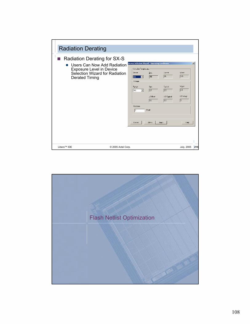
Radiation Derating
� Radiation Derating for SX-S
� Users Can Now Add RadiationExposure Level in DeviceSelection Wizard for RadiationDerated Timing
Flash Netlist Optimization

109
© 2005 Actel Corp. 217Libero™ IDE July, 2005
Netlist Optimization ConstraintsFlash Designs
� Attempts to Remove All Cells from Netlist that Have No Effect on Circuit’s Functional Behavior
� Reduces Overall Size of Design
� Produces Faster Place and Route Times
� Takes Advantage of Inverted Inputs of Logic Tiles
� By Default All Optimizations Are Performed on Netlist
� Original Netlist Preserved� Removed Cells Back-annotated with 0ns Delay in Timer
© 2005 Actel Corp. 218Libero™ IDE July, 2005
dont_optimizeFlash Designs
� Turns Off All Netlist Optimizations
� When Followed by One or More Netlist Optimization Options, this Statement Turns off Named Option(s).
� Syntaxdont_optimize {inverter buffer clocktree resettree const
dangling};
� Example:dont_optimize buffer inverter;
Disables buffer and inverter optimization

110
© 2005 Actel Corp. 219Libero™ IDE July, 2005
optimizeFlash Designs
� Turns On All Netlist Optimizations
� When Followed by One or More Netlist Optimization Options, this Statement Turns On Named Optimization Option(s)
� Syntaxoptimize {inverter buffer clocktree resettree const dangling};
� Example:optimize buffer inverter; Enables buffer and inverter
optimization
© 2005 Actel Corp. 220Libero™ IDE July, 2005
Netlist Optimization ConstraintsOptions
� buffer - Removes All Buffers Provided Maximum Fanout Not Exceeded
� inverter - Removes All Inverters Provided Maximum Fanout Not Exceeded
� clocktree - Removes All Inverters and Buffers in Nets Connected to Clock Inputs on All Flip-Flop Cell Types
� resettree - Removes All Inverters and Buffers in Nets Connected to Reset Inputs on All Flip-Flop Cell Types
� const - Replaces All Logical Elements with One or More Constant Inputs (Connected to Logical “1” or “0”) by Simplified Logic Function
� If Replacement Logic Function Is Inverter or Buffer, that Element Is Removed
� dangling - Recursively Removes All Cells Driving Unconnected Nets

111
© 2005 Actel Corp. 221Libero™ IDE July, 2005
set_max_fanout
� May Retain Buffers and Inverters in Netlist
� Removes All Buffers and Inverters whose Elimination Does Not Exceed Specified Fanout
� Use this Constraint if Design Has High-Fanout Net in Critical Paths
� Syntax� set_max_fanout <value>;
� Global Command
� set_max_fanout <value> Net_name;
� Single Net or Set of Nets (*)
� set_max_fanout <value> Block_name;
� All Nets of Block Block_name
© 2005 Actel Corp. 222Libero™ IDE July, 2005
dont_touch
� Selectively Disables Optimization of Named Hierarchical Instances
� Wildcard (*) Isolates All Sub-Blocks Under Named Block
� Syntaxdont_touch hier_net_name [, hier_net_name];
� Exampleoptimize buffer inverter;
dont_touch /U1/myblock/*;
Enables Only Buffer and Inverter Optimization Types. Optimizes All Instances except those Contained in Block /U1/myblock.

112
© 2005 Actel Corp. 223Libero™ IDE July, 2005
Import LogFlash Designs
� Import Log Written after Compile Step in Designer� Created under <name>.dtf directory
� What it Reveals� Promoted Globals
� Distribution of Fanout
� Device Utilization (RAMs, PLLs, IOs, Global Routes, Logic)
� Internal and External Nets (Min, Average and Max fanout)
� High Fanout Net Candidates to be Mapped to Spines
� Internal Clocks
© 2005 Actel Corp. 224Libero™ IDE July, 2005
. . .
Compile Output:
NOTE [removed_pwr_gnd_cells]:
Removed 2 power/ground cells from the design.
Optimizing Netlist.
Promoting nets to globals.
Following nets are possible candidates for Globals/Spines :
Fanout Type Driver Name
48 CLK_NET CLK_pad/MUXTILE CLK_c
48 SET/RESET_NET RESET_pad/MUXTILE RESET_c
Following nets are assigned to global resources:
Fanout Name
48 CLK_c
48 RESET_c
. . .
Designer Import LogFlash Designs
Nets assigned to global resources
Removed cells

113
© 2005 Actel Corp. 225Libero™ IDE July, 2005
Designer Import Log (cont.)
. . .
I/O Cells: Core cells:
| Instances | Gates | Tiles
Input. IOs: 2 ----------|-----------|--------|-------
Bidir IOs: 0 Logic | 81 | 185 | 81
Output IOs: 16 Storage | 48 | 384 | 48
Global IOs: 2 RAM/FIFO | 0 | 0 | 0
Internal Global: 0 | | |
----------------------- ----------|-----------|--------|-------
Total IOs: 20 Total | 129 | 569 | 129
Nets | Count | Average Fanout | Max. Fanout
---------------|--------|----------------|------------
Global | 2 | 48.0 | 48
External | 18 | 2.9 | 20
Internal | 113 | 1.9 | 16
---------------|--------|----------------|------------
Total | 133 | 2.7 | 48
. . .
Actual number of tiles used
Net statistics
© 2005 Actel Corp. 226Libero™ IDE July, 2005
Identifying Removed CellsFlash Designs
While Compile or Layout Is Running, Temporary File Named deleted_blocksIs Created under <name>.dtf Directory
� Lists All Deleted Cells
� This File Automatically Removed after Layout Is Finished
Save File before Layout Completes or Run Place Option without Route

114
© 2005 Actel Corp. 227Libero™ IDE July, 2005
Netlist Optimization ExampleFlash Designs
-- example to test APA optimization
library ieee;
use ieee.std_logic_1164.all;
entity test is
port (A, B, presetn, resetn, clk: in std_logic;
out1, out2, Q1, Q2: out std_logic);
end test;
architecture RTL of test is
begin
process (clk, resetn)
begin
if (resetn = '0') then Q1 <= '0';
elsif (clk 'event and clk = '0') then Q1 <= A;
end if;
end process;
process (clk, resetn, presetn)
begin
if (resetn = '0') then Q2 <= '0';
elsif (presetn = '0') then Q2 <= '1';
elsif (clk 'event and clk = '0') then Q2 <= B;
end if;
end process;
out1 <= A and not B;
out2 <= not A xor not B;
end RTL;
Deleted blocks
© 2005 Actel Corp. 228Libero™ IDE July, 2005
Successful Compile
� Compile Button Turns Green if Compile Completes Successfully
� Errors Indicated in Designer Log Window

115
MultiView Navigator
© 2005 Actel Corp. 230Libero™ IDE July, 2005
MultiView Navigator
� MultiView Navigator Includes the Following Tools:
� PinEditor, I/O Attribute Editor, NetlistViewer, and ChipPlanner
� Allows Cross-probing Among Different Designer Tools

116
© 2005 Actel Corp. 231Libero™ IDE July, 2005
MultiView Navigator
DesignWindow
World ViewWindow
LogWindow
WorkingArea
Toolbar IconsZoom Controls
© 2005 Actel Corp. 232Libero™ IDE July, 2005
MultiView NavigatorWindows
� Design Window
� View Design as Logical Blocks, Physical Elements, Ports, Nets, and Regions
� World View Window
� Shows Position of Current Viewing Window Relative to Chip
� Working Area Shows Current Active Tools
� Tile or Cascade Active Tools
� Log Window Keeps Running Log of Activity
� Output – Shows All Messages
� Errors – Shows Error Messages
� Warnings – Shows Warning Messages
� Info – Shows Informational Messages
� Find Window – Keeps Result of Find Function for Later Usage

117
© 2005 Actel Corp. 233Libero™ IDE July, 2005
MultiView Navigator FeaturesMessage Bar
� Hierarchical Error / Info Message Display
� Summary Line Shown in New Message Bar
� Expands on Demand to Show More Details
� Copy / Clear Messages
� Most Messages Transitory (Removes Clutter)
� Reduced Number of Tabs (Removes Clutter)
� Ongoing Effort to Improve Message Content
© 2005 Actel Corp. 234Libero™ IDE July, 2005
MultiView Navigator Toolbar
� File ->
� Commit – Writes any Changes Made in Editors to Design
� Prelayout Check – Verifies Placement Changes in Editors Are Legal
� Edit ->
� Undo/Redo – Allows User to Undo a Mistake or Redo an Accidental Undo
� Find – Enables Find Interface
� Zoom Controls
� Zoom Region, Zoom In, Zoom Out, Zoom to Fit
� Assignment Options
� Place, Unplace, Lock (Fix), Unlock (Unfix)
� Tools Menu
� ChipPlanner, PinEditor, NetlistViewer, I/O Attribute Editor

118
© 2005 Actel Corp. 235Libero™ IDE July, 2005
MultiView NavigatorPrelayout Checker
� Infeasible Constraints Identified pre-Layout
� Automatically Runs when You Commit from MVN
� Users Can Run Using MVN Command Tools->DRC
� Enhanced Checks
� Overlapping Region Checks
� Resource Overbooking
� I/O Technology Checks
© 2005 Actel Corp. 236Libero™ IDE July, 2005
MultiView NavigatorFind / Search
� Search for Instances, Nets or Ports
� Wildcard (*) Matching
� Advanced Options - Choice of Log Window Pane for Search Results
� Cross-probing from Find Tab to the other Four Windows

119
PinEditor
© 2005 Actel Corp. 238Libero™ IDE July, 2005
Pin Assignment Options
� I/O Locations Can Be Assigned as Follows:
� Automatically by Designer Software during Layout
� By Importing:
� . Gatefield Constraint File (.gcf) (ProASIC and ProASICPLUS)
� Manually using PinEdit Tool in Designer
� Pin Assignments May Be Exported for Later Use

120
© 2005 Actel Corp. 239Libero™ IDE July, 2005
MultiView NavigatorPinEditor
� Graphical Pin Location Editor
� Drag and Drop Placement of Pins
� Fix Pin Locations for Subsequent Place and Route Runs
� Flip Display
� Enables Assignments as if Looking from Top or Bottom of Chip
� Pinout Can Be Printed for Documentation
© 2005 Actel Corp. 240Libero™ IDE July, 2005
I/O FeaturesAxcelerator
� I/O Bank Configuration
� Select Bank
� Select I/O Standards
� Incompatible OptionsDisappear when Selecting I/O Standards
� Select Low-power Mode
� Select Input Delay
121
© 2005 Actel Corp. 241Libero™ IDE July, 2005
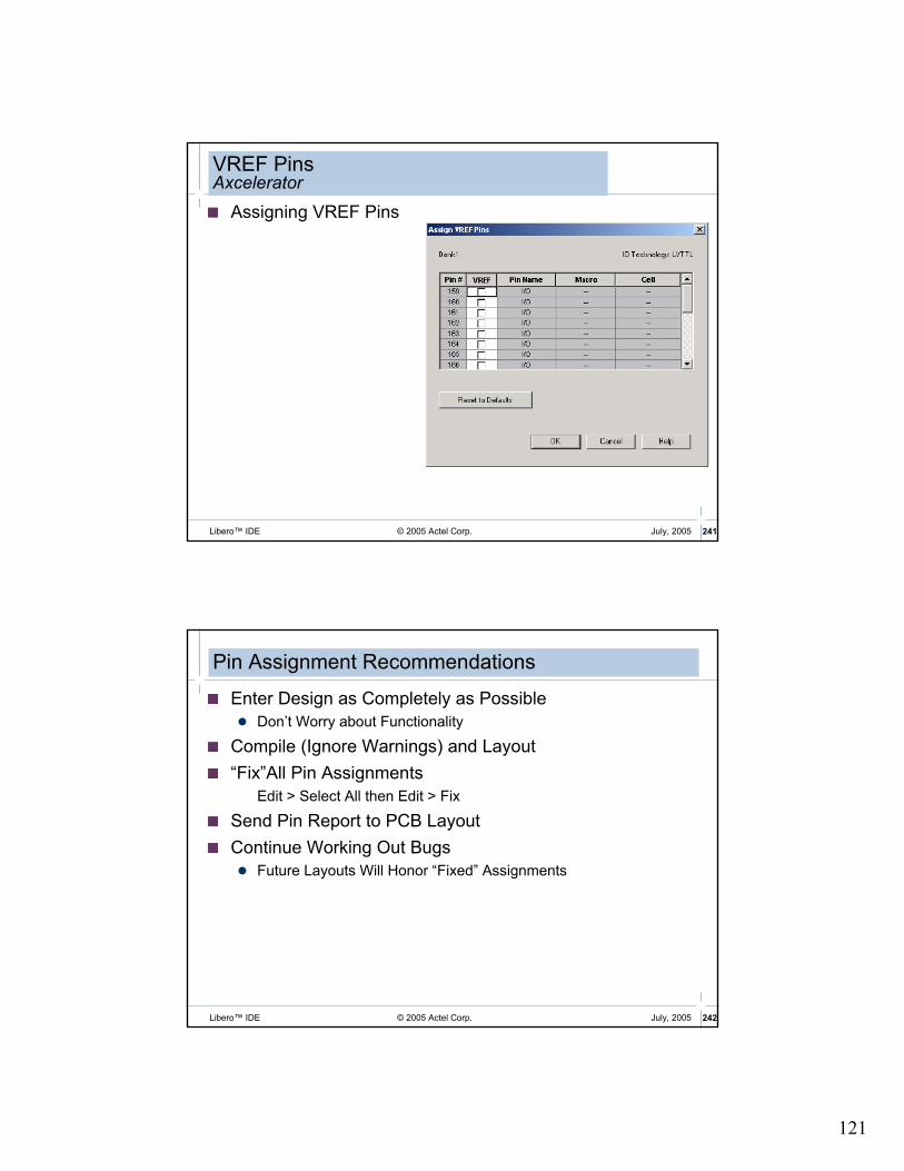
VREF PinsAxcelerator
� Assigning VREF Pins
© 2005 Actel Corp. 242Libero™ IDE July, 2005
Pin Assignment Recommendations
� Enter Design as Completely as Possible
� Don’t Worry about Functionality
� Compile (Ignore Warnings) and Layout
� “Fix”All Pin Assignments
Edit > Select All then Edit > Fix
� Send Pin Report to PCB Layout
� Continue Working Out Bugs
� Future Layouts Will Honor “Fixed” Assignments

122
© 2005 Actel Corp. 243Libero™ IDE July, 2005
Exporting Pin Report
� Pin Report Can be Exported from Designer
© 2005 Actel Corp. 244Libero™ IDE July, 2005
Exporting Pin Constraint File
� Pin Constraint File Can be Exported from Designer
File Type
File Extension Family
PIN file *.pin
ACT1, ACT2, ACT3, MX, XL, DX, SX, SX-A, eX
Gatefield Constraint file *.gcf
ProASIC,
ProASIC PLUS
Physical Design Constraint *.pdc Axcelerator

123
I/O Attribute Editor
© 2005 Actel Corp. 246Libero™ IDE July, 2005
MultiView Navigator I/O Attribute Editor
�Input/Output Attribute Editor
� Select (Varies by Family):
� I/O Standard
� I/O Threshold
� Slew Rate
� I/O Power-up State
� Enter Load Capacitance
� Does Not Change SDF File Generation
�Spreadsheet-like Sort, Copy, Paste

124
© 2005 Actel Corp. 247Libero™ IDE July, 2005
MultiView Navigator I/O Attribute Editor (cont.)
With multiple rows selected, changing the value of a drop-down item with CTRL key pressed will change the value for all rows
Hold down CTRL key to select multiple rows
Double click on column to sort display by that column
Netlist Viewer

125
© 2005 Actel Corp. 249Libero™ IDE July, 2005
MultiView NavigatorNetlist Viewer
� Displays Netlist in Hierarchical Manner, Providing Logical View of Design
� Netlist Viewer Can Explore each Level of Hierarchy and Trace Signals
Open Netlist Viewer
© 2005 Actel Corp. 250Libero™ IDE July, 2005
MultiView NavigatorNetlist Viewer (cont.)
Search Window –shows results of searches
Schematic View Window –displays a graphical representation of the netlist
126
© 2005 Actel Corp. 251Libero™ IDE July, 2005
MultiView NavigatorNetlist Viewer (cont.)
� Viewing Options
� Push, Pop, Jump to Top
� Go to First Page, Go to Last Page, Go to Next Page, Go to Last Page
� Right-click on Net to Follow Net to Other Pages or Net Driver
� Highlight, Highlight Append, un-Highlight, un-Highlight All
� Allows Page Splitting
� Allows User to Decide if All Elements on that Level Are Shown as Single Page
© 2005 Actel Corp. 252Libero™ IDE July, 2005
MultiView NavigatorNetlist Viewer
� View pre- and post-Optimized Netlists
� Pre-optimized Netlist Is Original Hierarchical Netlist
� Post-optimized Netlist is Flattened
� Reflects what other Tools Use (ChipEdit, PinEdit)

127
ChipPlanner
© 2005 Actel Corp. 254Libero™ IDE July, 2005
ChipPlanner
� Editing and Floorplanning
� ChipPlanner Capabilities:
� Editing
� Place, Unplace, or Move Logic and I/O
� View Macro Placements Made during Layout
� View Net Connections with Ratsnest or Route View
� View Architectural Boundaries
� View and Edit Silicon Features, such as I/O Banks
� View Placement and Routing of Paths when Used with Timer
� Floorplanning
� Create and Assign Logic or Nets to Regions
� Cross-probe with Silicon Explorer to Select Probes

128
© 2005 Actel Corp. 255Libero™ IDE July, 2005
ChipPlanner Terminology
� Region� Defined sub-Portion of Die
� Shapes - Rectangular or Rectilinear (Union of Rectangles)
� Types:� Empty - No Logic Can Be Put into this Region
� Inclusive - Assigned Logic Must Be Put into this Region
Other Unassigned Logic Can Be Added to this Region by Layout
� Exclusive - Only Assigned Logic Can Be Put into this Region
Not Supported for APA or A500K
� Assign
� Place Logic into Particular Region or Location
� Lock
� Finalizes Allocation of Logic in Particular Location
© 2005 Actel Corp. 256Libero™ IDE July, 2005
ChipPlannerEditing and Floorplanning
� Drag Logic or I/O to Desired Location
� ChipPlanner Floorplanning Functions
� Create Logic Region
� Create Empty Region
� Select Region
� Move Region
� Delete Region
� Resize Region
� Assign/Unassign Logic to Region
� Regions Can Span Logic, Memory Cells and I/O
Create empty region
Create inclusive region
Create exclusive region
Delete region
Assign / Unassign
Create local clock region
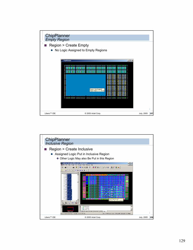
129
© 2005 Actel Corp. 257Libero™ IDE July, 2005
ChipPlannerEmpty Region
� Region > Create Empty
� No Logic Assigned to Empty Regions
© 2005 Actel Corp. 258Libero™ IDE July, 2005
ChipPlannerInclusive Region
� Region > Create Inclusive
� Assigned Logic Put in Inclusive Region
� Other Logic May also Be Put in this Region

130
© 2005 Actel Corp. 259Libero™ IDE July, 2005
ChipPlannerExclusive Region (Axcelerator)
� Region > Create Exclusive
� Only assigned logic placed in exclusive region
© 2005 Actel Corp. 260Libero™ IDE July, 2005
ChipPlannerLocal Clock Region (Flash)
� Region > Create Local Clock
� Assign net to a spine region graphically
� All logic connected with the net will be assigned to the spine region

131
© 2005 Actel Corp. 261Libero™ IDE July, 2005
ChipPLannerRegion Color Control
� Individual Region Color Control
� Regions Have Different Default Colors Based on Types
� Can Change Each Region’s Default Color
� Region Colors Saved in .adb File
� Region Colors Reset to Defaults upon Recompile
© 2005 Actel Corp. 262Libero™ IDE July, 2005
ChipPlannerRegion Properties
� Region > Properties
� Indicates:
� Region Type
� Region Width, Height and Origin
� Region Usage
� Shows Region Default Color
� Default Color Can be Changed
� Also Provides Access to Assignment Window
Region size and utilization
Change region color

132
© 2005 Actel Corp. 263Libero™ IDE July, 2005
MultiView NavigatorRegion Color Control Example
© 2005 Actel Corp. 264Libero™ IDE July, 2005
ChipPlannerLogic Assignment
� Two Logic Assignment Methods
� Assignment Window (Region > Assign/Unassign Logic…)
� Provides Search and Selection Capability
� Also Available from Region Properties Dialog Box
� Drag and Drop Logic into Region
� Checkmark Indicates Assigned Logic
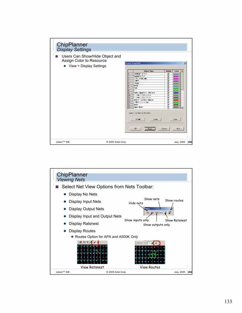
133
© 2005 Actel Corp. 265Libero™ IDE July, 2005
ChipPlannerDisplay Settings
� Users Can Show/Hide Object and Assign Color to Resource
� View > Display Settings
© 2005 Actel Corp. 266Libero™ IDE July, 2005
ChipPlannerViewing Nets
� Select Net View Options from Nets Toolbar:
� Display No Nets
� Display Input Nets
� Display Output Nets
� Display Input and Output Nets
� Display Ratsnest
� Display Routes
� Routes Option for APA and A500K Only
Hide nets
Show inputs only
Show outputs only
Show Ratsnest
Show routesShow nets
View Ratsnest View Routes
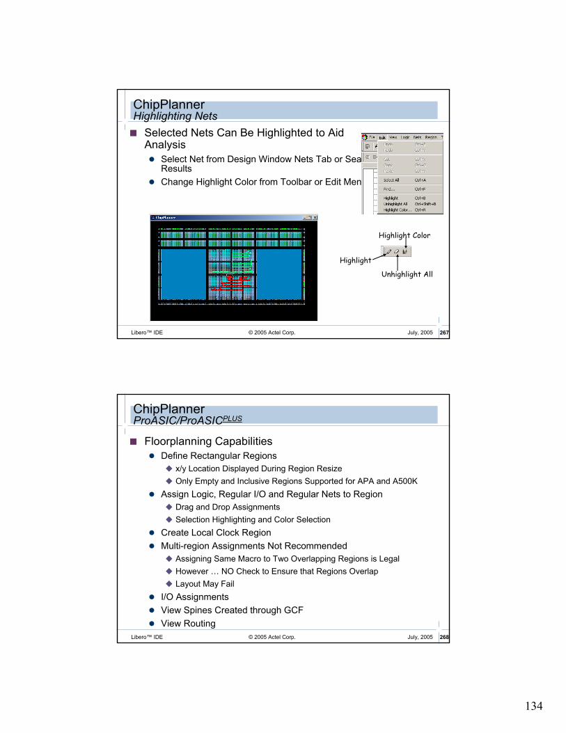
134
© 2005 Actel Corp. 267Libero™ IDE July, 2005
ChipPlannerHighlighting Nets
� Selected Nets Can Be Highlighted to Aid Analysis
� Select Net from Design Window Nets Tab or Search Results
� Change Highlight Color from Toolbar or Edit Menu
Highlight
Unhighlight All
Highlight Color
© 2005 Actel Corp. 268Libero™ IDE July, 2005
ChipPlannerProASIC/ProASICPLUS
� Floorplanning Capabilities
� Define Rectangular Regions
� x/y Location Displayed During Region Resize
� Only Empty and Inclusive Regions Supported for APA and A500K
� Assign Logic, Regular I/O and Regular Nets to Region
� Drag and Drop Assignments
� Selection Highlighting and Color Selection
� Create Local Clock Region
� Multi-region Assignments Not Recommended
� Assigning Same Macro to Two Overlapping Regions is Legal
� However … NO Check to Ensure that Regions Overlap
� Layout May Fail
� I/O Assignments
� View Spines Created through GCF
� View Routing

135
© 2005 Actel Corp. 269Libero™ IDE July, 2005
Silicon SupportProASIC/ProASICPLUS
� Multi-type Region Support
� Region Support for RAM
� LocalClock Regions Can Include RAM and I/O
� Controlled by Compile Option (Designer -> Options -> Compile)
� Need to Recompile after Modifying Option
� Default is ON for New Designs from Designer 6.0 on
Top1 Top2 Top3 …
1) Core + memory
core
i/o i/o i/o
i/o
i/o
i/o
2) Core + memory + I/O
spine
RAM block
© 2005 Actel Corp. 270Libero™ IDE July, 2005
ChipPlannerAxcelerator
� Floorplanning Capabilities
� Define Rectangular Regions
� Empty, Exclusive and Inclusive Region Support for Axcelerator
� Modify Region types (Inclusive / Exclusive)
� Assign Logic and Nets to Region
� I/O Assignments
� PLL and RAM Assignments
� Drag and Drop Assignments
� Multi-region AssignmentsNOT Recommended
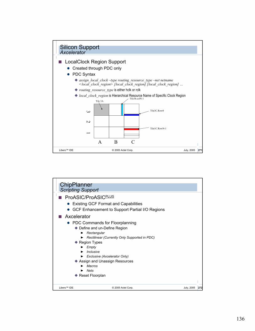
136
© 2005 Actel Corp. 271Libero™ IDE July, 2005
Silicon SupportAxcelerator
� LocalClock Region Support
� Created through PDC only
� PDC Syntax
� assign_local_clock –type routing_resource_type –net netname <local_clock_region> [local_clock_region] [local_clock_region] …
� routing_resource_type is either hclk or rclk
� local_clock_region is Hierarchical Resource Name of Specific Clock Region
Tile3C.Row0
Tile 3A
Tile1C.RowN-1
A B C
3 2
1
Tile3b.colN-1
© 2005 Actel Corp. 272Libero™ IDE July, 2005
ChipPlannerScripting Support
� ProASIC/ProASICPLUS
� Existing GCF Format and Capabilities
� GCF Enhancement to Support Partial I/O Regions
� Axcelerator� PDC Commands for Floorplanning
� Define and un-Define Region
Rectangular
Rectilinear (Currently Only Supported in PDC)
� Region Types
Empty
Inclusive
Exclusive (Axcelerator Only)
� Assign and Unassign Resources
Macros
Nets
� Reset Floorplan

137
© 2005 Actel Corp. 273Libero™ IDE July, 2005
MultiView NavigatorLogicalCone
� Helps View Critical Portions of Netlist
� Identify Critical Paths using Timer
� Add this Logic to LogicalCone
� Incrementally Add / Remove Logic from Cone
� CrossProbe from / to LogicalCone
� All NetlistView Features available in LogicalCone
� New LogicalCone Tab in Hierarchy Window
� New LogicalCone Menu Accessible from NetlistViewer
� Can Simultaneously Create Multiple Cones
� Set of Macros Can Be Highlighted, then Added to Cone
� LogicalCone Data No Longer Valid after Recompile
� Applies to All Families Supported by MVN
© 2005 Actel Corp. 274Libero™ IDE July, 2005
LogicalConeUser Interface

138
ChipEditor
© 2005 Actel Corp. 276Libero™ IDE July, 2005
ChipEditorOlder Antifuse Families
ChipEditor icon

139
© 2005 Actel Corp. 277Libero™ IDE July, 2005
ChipEditorOlder Antifuse Families
� Graphical Placement Editor
� Place Logic Modules and I/O
� ChipEdit Shows Routing Congestion with “Rats Nest” Views
� Gives More Control to Power User
© 2005 Actel Corp. 278Libero™ IDE July, 2005
ChipEditorViewing Routing
� Rats Nest View Shows Connectivity� Example – CLKBUF Connected to Several Registers

140
© 2005 Actel Corp. 279Libero™ IDE July, 2005
ChipEditorViewing Routing (cont.)
� Minimum Spanning Tree Mode
� Shows Connectivity between Selected Macros
Timing Constraints and Analysis

141
© 2005 Actel Corp. 281Libero™ IDE July, 2005
Designer Timing Analysis Tools
� Timer
� Static Timing Analysis Tool
� Generates User-specified Measurements
� Click Timer Icon from Designer GUI
� Timing Report
� Generates Standard Set of Measurements
� Report Can Be Printed or Saved to File
© 2005 Actel Corp. 282Libero™ IDE July, 2005
Timer
� Select Timer in Graphical Flow Manager
� Functions:
� Define Clock Constraints and Exceptions
� Define Path Constraints
� Define Global Stop Sets
� Define Global Pass Sets
� Information Used to
� Generate Timing Reports
� Assist in Timing Verification in Timer
� Constrain Timing-driven Layout Engine

142
© 2005 Actel Corp. 283Libero™ IDE July, 2005
TimerSummary Tab
� Displays Maximum Frequency for Clock(s) in Design
� Clock Selected from Pull-down Window
� Enter Clock Frequency Requirement
� Constraints Entered on Clock Tab Used for Register-to-Register Constraints
Select Clock
© 2005 Actel Corp. 284Libero™ IDE July, 2005
TimerClock Tab
� Specify Global Clock Constraints
� Select Clock from Pull-down Menu
� Enter Period and Duty Cycle
� Enter Clock Exceptions to Make Exceptions to Global Clock Constraints
� Useful for Multicycle Path Definition
Specify clock exceptions
Select Clock
Expand buttonopens expanded clock path window

143
© 2005 Actel Corp. 285Libero™ IDE July, 2005
TimerPaths Tab
� Define Path Constraints for Signal Groups
� Default or User-defined
� Four Default Groups:
� Inputs to Registers
� Registers to Registers
� Registers to Outputs
� Inputs to Outputs
� Clock Selected from Pull-down Menu
� Additional Paths Can Be Defined
� Edit -> Add Set of Paths
Constraints for default groups entered on Summary tab
© 2005 Actel Corp. 286Libero™ IDE July, 2005
TimerBreaks Tab
� Provides Mechanism for Forcing Paths to Be Don't Cares

144
© 2005 Actel Corp. 287Libero™ IDE July, 2005
Timer Preferences
�Select File -> Preferences
�Longest/Shortest Path(s)
� Maximum Number of Paths to Display
�Expanded Path(s) in List
� Maximum Number of Expanded Paths to Display
�Show
� Longest – Maximum Delays� Used for Setup Calculation
� Shortest – Minimum delay� Used for Hold-time Calculation
Sort by
� Actual Delay
� Slack
© 2005 Actel Corp. 288Libero™ IDE July, 2005
Timer Preferences (cont.)
� Path Selection
� Critical Paths Only
� Shows Maximum Delay to any End Terminal Only
� Paths Between Any Pair
� Shows All Paths Conforming to Defined Filters
� Break Path at Register
� Clk/G Pins Option - Include / Exclude Clk / G pins in/from Path Starting/Ending Points
� Clr/Pre Pins Option – Include / Exclude Clr / Pre Pins in/from Path Starting/Ending Points
� Data Pins of Latches – Include / Exclude Latch Data Pins in/from Path Starting or Ending Points
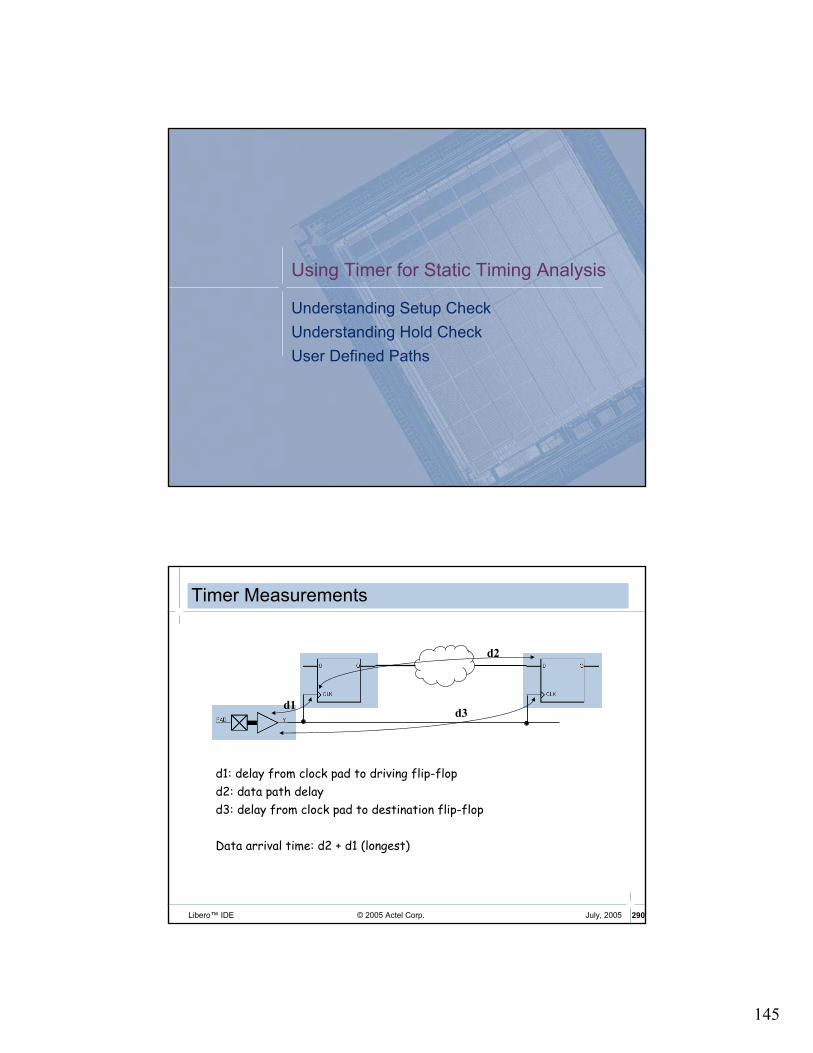
145
Using Timer for Static Timing Analysis
Understanding Setup Check
Understanding Hold Check
User Defined Paths
© 2005 Actel Corp. 290Libero™ IDE July, 2005
Timer Measurements
d1d3
d2
d1: delay from clock pad to driving flip-flop
d2: data path delay
d3: delay from clock pad to destination flip-flop
Data arrival time: d2 + d1 (longest)

146
© 2005 Actel Corp. 291Libero™ IDE July, 2005
Maximum Clock FrequencySame Edge of Clock
Min clk period = d2(longest) + setup – d3(shortest)
+ d1 (longest)
d1 and d3 are displayed in timer info window
d2 is displayed in timer path tab and info window
Expand button opens expanded clock path window to display path used to calculate the maximum clock frequencyConstraints can be entered summary tabViolations indicated with “X”
Clock edge indication
© 2005 Actel Corp. 292Libero™ IDE July, 2005
Maximum Clock Frequency CalculationSame Edge of Clock
� Info Window Displays Clock Network Delays
15.57
+ 0.77
-0.85
+ 0.87
= 16.36
Min Period
Longest Datapath delay

147
© 2005 Actel Corp. 293Libero™ IDE July, 2005
Maximum Clock FrequencyOpposite Edges of Clock
d1d3
d2
Min clk period* / 2 = d2(longest) + setup – d3(shortest) + d1 (longest)
d1 and d3 are displayed in timer info windowd2 is displayed in timer path tab and info window
*uses duty cycle entered on Clock tab
© 2005 Actel Corp. 294Libero™ IDE July, 2005
Maximum Clock Frequency CalculationOpposite Edges of Clock
� Timer Calculates Maximum Frequency when Opposite Edges Are Used Based on Duty Cycle
3.53
+ 0.77
-1.91
+ 1.93
= 4.32
x 2
= 8.64
Min Period

148
© 2005 Actel Corp. 295Libero™ IDE July, 2005
Setup Check
� Data Must Be Stable and Valid for Specified Amount of Time before ‘Capture’ Clock Edge
� Key Point: FF1.Q Changes with FF1.clk. Setup Is Checked on Captured Data (NOT Launched Data)
FF1:CLK
FF3:CLK
Setup Time of FF3
© 2005 Actel Corp. 296Libero™ IDE July, 2005
TimerSetup Check
� Longest Delays Used for Setup Check
� Select Longest in Timer Preferences Dialog Box
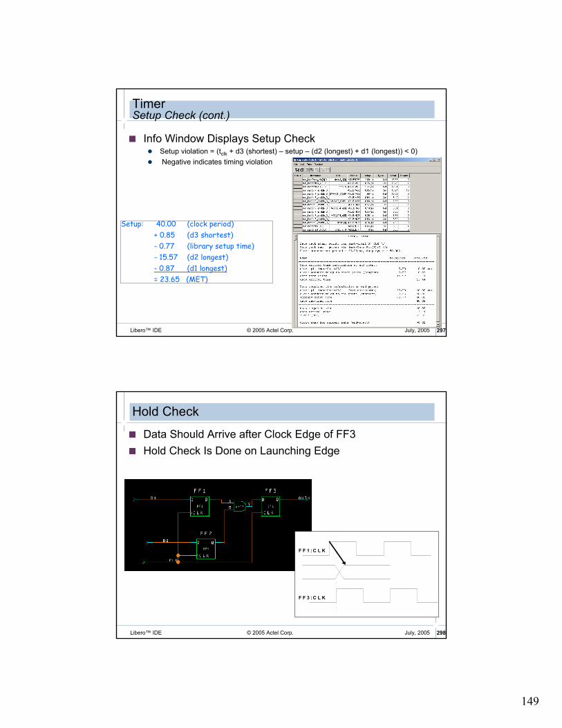
149
© 2005 Actel Corp. 297Libero™ IDE July, 2005
TimerSetup Check (cont.)
� Info Window Displays Setup Check� Setup violation = (tclk + d3 (shortest) – setup – (d2 (longest) + d1 (longest)) < 0)
� Negative indicates timing violation
Setup: 40.00 (clock period)
+ 0.85 (d3 shortest)
- 0.77 (library setup time)
- 15.57 (d2 longest)
- 0.87 (d1 longest)
= 23.65 (MET)
© 2005 Actel Corp. 298Libero™ IDE July, 2005
Hold Check
� Data Should Arrive after Clock Edge of FF3
� Hold Check Is Done on Launching Edge
F F 1 : C L K
F F 3 : C L K

150
© 2005 Actel Corp. 299Libero™ IDE July, 2005
TimerHold Check
� Shortest Delays Used for Hold Check
� Select Shortest in Timer Preferences Dialog Box
� Need to Recalculate Timer Delays
© 2005 Actel Corp. 300Libero™ IDE July, 2005
TimerHold Check (cont.)
� Info Window Displays Hold Check� Hold time violation = (d2 (shortest) + d1 (shortest) – d3 (longest) < 0)
� Negative indicates timing violation
Hold: 11.93 (d2 shortest)
+ 0.87 (d1 shortest)
- 0.85 (d3 longest)
= 11.95 (Met)
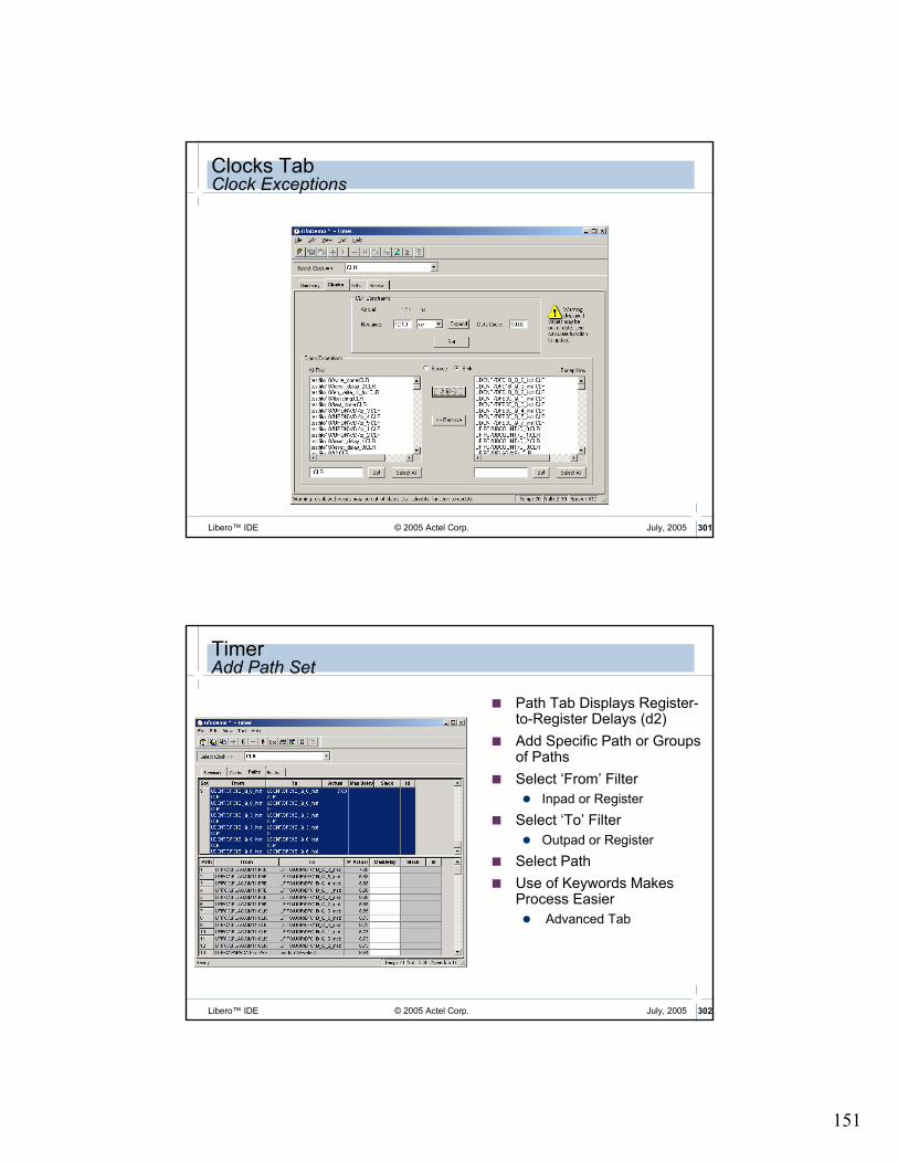
151
© 2005 Actel Corp. 301Libero™ IDE July, 2005
Clocks TabClock Exceptions
© 2005 Actel Corp. 302Libero™ IDE July, 2005
TimerAdd Path Set
� Path Tab Displays Register-to-Register Delays (d2)
� Add Specific Path or Groups of Paths
� Select ‘From’ Filter
� Inpad or Register
� Select ‘To’ Filter
� Outpad or Register
� Select Path
� Use of Keywords Makes Process Easier
� Advanced Tab

152
© 2005 Actel Corp. 303Libero™ IDE July, 2005
� Enter constraints for User-defined Groups on Paths Tab
� Select Clock from Drop-down Menu
� Use Commit Command in File Menu to Save Constraints
TimerConstraining User Paths
Constraint for userdefined group
Constraint id
User Path
© 2005 Actel Corp. 304Libero™ IDE July, 2005
Timing Analysis
� Timer Performs Static Timing Analysis Using either Pre-Layout (Estimated) or Post_Layout (Actual) Timing Data
� Shows Performance Relative to Constraints Entered
� Default Groups Show:
� Inputs to Register
� Register to Register,
� Register to Output
� Inputs to Outputs
Pre-Layout delay
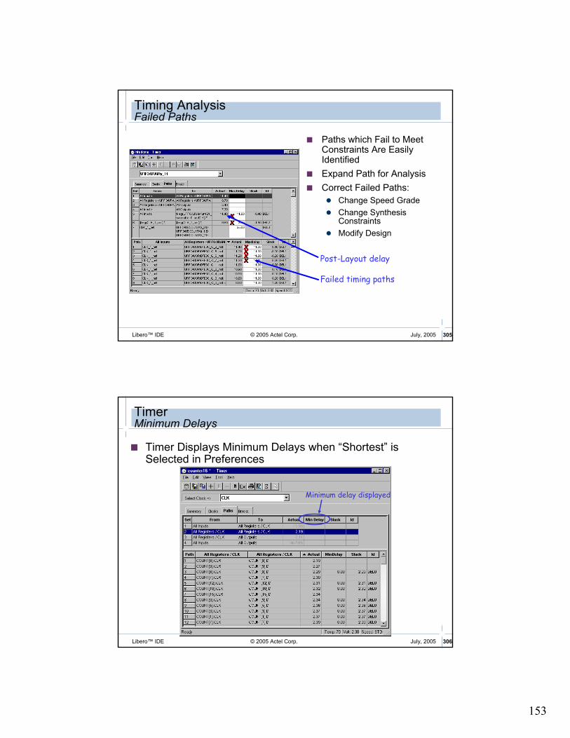
153
© 2005 Actel Corp. 305Libero™ IDE July, 2005
Timing AnalysisFailed Paths
� Paths which Fail to Meet Constraints Are Easily Identified
� Expand Path for Analysis
� Correct Failed Paths:
� Change Speed Grade
� Change Synthesis Constraints
� Modify Design
Failed timing paths
Post-Layout delay
© 2005 Actel Corp. 306Libero™ IDE July, 2005
TimerMinimum Delays
� Timer Displays Minimum Delays when “Shortest” is Selected in Preferences
Minimum delay displayed

154
© 2005 Actel Corp. 307Libero™ IDE July, 2005
TimerMinimum Delays (cont.)
� Minimum Delays Displayed on Timer Summary Tab
Window re-named to reflect minimum delays
Required min delays shadowedno user input accepted
© 2005 Actel Corp. 308Libero™ IDE July, 2005
TimerOutdated Data
� Outdated Data Grayed Out in GUI
� Users Must Update manually
� Use Recalculate Buttons or Tools > Calculate Delays
Data is grayed out after changing from “longest” to “shortest”
Re-calculate buttons
Warning indicates data is out of date
Min delays after re-calculating

155
© 2005 Actel Corp. 309Libero™ IDE July, 2005
TimerBreaks Tab – Global Stop Sets
� Any path Passing through Defined Stop Is Don't Care Regardless of Any Other Defined Delay
� Useful for Removing False Paths
© 2005 Actel Corp. 310Libero™ IDE July, 2005
Stop Set Example
Timer with no Stop set: Timer with $1I10:E in Stop set:
Don’t care path

156
© 2005 Actel Corp. 311Libero™ IDE July, 2005
TimerBreaks Tab – Global Pass Sets
� By Default, Timer Breaks All Signal Paths at Inputs of Flip-flops and Latches
� Global Pass Set Editor Provides Mechanism for Modifying Breaks to Be Pass-through Paths on All Input Pins of Flip-flops and Latches Except Data Input to Flip-flops
� Useful for Eliminating False Paths from Configuration and Control Registers
© 2005 Actel Corp. 312Libero™ IDE July, 2005
Pass Set Example
Timer with no Pass set: Timer with U1:CLR in Pass set:
Desired path

157
© 2005 Actel Corp. 313Libero™ IDE July, 2005
Identifying Combined Cells in Timer Antifuse Designs
� Timer Back-annotates 0ns Delay to Combined cells� Original Cells Remain in Netlist
0ns delay for U6 indicates it was combined with U5
© 2005 Actel Corp. 314Libero™ IDE July, 2005
Identifying Removed Cells in Timer Flash Designs
0ns delay for B_c_I indicates it was removed during netlist optimization

158
Timer SDC Constraints
© 2005 Actel Corp. 316Libero™ IDE July, 2005
Supported SDC Constraints
� Designer Currently Supports the Following Synopsys Design Constraints (SDC) for ProASICPLUS Devices:
� create_clock
� set_multicycle_path
� set_false_path
� set_max_delay
� More SDC Constraints Coming in Future Releases
� With Full SDC Support, GCF Constraints Will Be Dropped
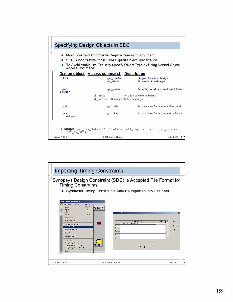
159
© 2005 Actel Corp. 317Libero™ IDE July, 2005
Specifying Design Objects in SDC
� Most Constraint Commands Require Command Argument
� SDC Supports both Implicit and Explicit Object Specification
� To Avoid Ambiguity, Explicitly Specify Object Type by Using Nested Object Access Command
Design object Access command Descriptionclock get_clocks Single clock in a design
all_clocks All clocks in a design
port get_ports An entry point to or exit point from a design
all_inputs All entry points to a design.
all_outputs All exit points from a design.
cell get_cells An instance of a design or library cell
pin get_pins An instance of a design port or library cell pin
Example: set_max_delay 15.00 -from [all_inputs] -to [get_clocks {MY_CK_SEL}]
© 2005 Actel Corp. 318Libero™ IDE July, 2005
Importing Timing Constraints
Synopsys Design Constraint (SDC) Is Accepted File Format for Timing Constraints
� Synthesis Timing Constraints May Be Imported into Designer

160
© 2005 Actel Corp. 319Libero™ IDE July, 2005
Exporting Timing Constraints
� Timing Constraints Entered in Timer Can Be Exported
� File Can Be Edited and Imported into Designer if Desired
© 2005 Actel Corp. 320Libero™ IDE July, 2005
Designer 6.1 TimerImproved Constraints Handling
� PALACE .sdc File Now Imported as Source
� Audited as Source File
� Can Still Be Imported as Auxiliary File post-Compile
compile
SynthesisSynthesis
PALACEPALACE
Generate design
constraints
Generate design
constraints
Menu select
GCF
netlist
SDC
Designer 6.1Timer
Layout
Import aux SDC constraints file
Import aux SDC constraints file
audited
unaudited
*True Synopsys Design Constraints

161
© 2005 Actel Corp. 321Libero™ IDE July, 2005
Designer 6.1 TimerMulti-cycle Path Constraints
� SDC Support for Multi-cycle Paths - All NGT Families
� APA (PA3)
� AX, AX-S
� SX-A, eX, SX-S
CKsource
CKsink
New setup relationshipDefault setup relationship
set_multicycle_path -setup 2 -from FF1 -to FF2
F
F
2
F
F
2
MyDesign
Clock
Generator
F
F
1
F
F
1CK
© 2005 Actel Corp. 322Libero™ IDE July, 2005
Designer 6.1 TimerOther Enhancements
� Fmax in Summary Tab Now Takes Duty Cycle into Account
� Sort by Slack on User-defined Sets
� Sort by Highest Negative Slack
� Now Supports Sort-by-slack and Sort-by-delay

162
Timer Reports
© 2005 Actel Corp. 324Libero™ IDE July, 2005
Timing Report
Tool -> Report Paths from Timer Main Menu
� Generates Standard Set of Measurements
� External Setup and Hold Times Can Be Included
� Report Can Be Printed or Saved to File
� Report Can also Be Generated from Designer Main Menu

163
© 2005 Actel Corp. 325Libero™ IDE July, 2005
Timing Violation Report
� Lists Timing Violations in Design
� Tool > Report Violations
© 2005 Actel Corp. 326Libero™ IDE July, 2005
Cross-ProbingTimer and MVN Tools
� Designers Can Cross-probe between Timer and MVN Tools

164
© 2005 Actel Corp. 327Libero™ IDE July, 2005
Cross ProbingTimer and ChipEditor
� Timer Expanded Path Can Cross-probe with ChipEdit and Netlist Viewer
© 2005 Actel Corp. 328Libero™ IDE July, 2005
Constraint Recommendations
� Set Realistic Constraints
� Set Sufficient Constraints
� Don’t Over constrain
� Improperly-Constrained Design Can Lead to Long Run Times, Multiple Iterations and/or Sub-optimal Results
� max_delay Is Not Equivalent to Clock Constraint or Clock Period
� Use Exceptions
� Use Global Stop Set

165
© 2005 Actel Corp. 329Libero™ IDE July, 2005
Layout
� Assign Physical Locations to Unassigned I/Os
� Place Logic Modules
� Assign Routing Tracks to Nets
� Calculate Detailed Delays for All Paths
© 2005 Actel Corp. 330Libero™ IDE July, 2005
Layout ModesSX Architecture
�Layout Mode
� Timing-Driven: Constraints Defined in Timer
� De-selecting Timing-Driven Layout Selects Standard Layout
�Incremental Placement
� Lock Existing Placement: Treats All Unchanged Macros as Fixed Placements
� De-selecting Allows Placer to Relocate Unchanged Macros if Necessary
�Multiple Passes
� P&R Runs Multiple Times
� User Specifies Number of Times and which Results to Save (Best or All)
�Advanced Options Allow Additional Control of Timing-driven Placement Engine
� SX, SXA and eX Families

166
© 2005 Actel Corp. 331Libero™ IDE July, 2005
Advanced Layout OptionsSX Architecture
� Extended Run
� Directs Layout to Use Larger Number of Iterations during Optimization to Improve Layout Quality
� Causes Layout to Run up to 5 Times Longer
� Effort Level
� Specifies Duration of Timing-driven Phase of Optimization during Layout as Percentage of Default Duration
� Default Value is 100
� Selectable Range from 25 to 500
� Reducing Effort Level also Reduces Run Time of Timing-driven Place and Route (TDPR).
� With Effort Level of 25, TDPR Is Almost Four Times Faster than Default of 100
However, with Fewer Iterations Performance May Suffer
� Routability May or May Not Be Affected
© 2005 Actel Corp. 332Libero™ IDE July, 2005
Advanced Layout Options (cont.)SX Architecture
� Timing Weight
� Setting this Option Changes Weight of Timing Objective Function
� Recommended Range: 10 - 150 (Default is 100)
� Bias TDPR in Favor of either Routability or Performance
� Weight Is Specified as Percentage of Default Weight
� Value of 100 Has No Effect
� Value Less than 100 – More Emphasis on Routability and Less on Performance
Appropriate for Design that Fails to Route with TDPR
� Value Higher than 100 – More Emphasis on Performance
BUT … Very High Value of Timing Weight Might Degrade Performance!

167
© 2005 Actel Corp. 333Libero™ IDE July, 2005
Layout OptionsAxcelerator
�Layout Mode
� Timing-Driven: Constraints Defined in Timer� De-selecting Causes Standard Layout to Be
Used
�Place and Route Tools
� Can Be Turned On or Off
�Incremental Placement and Routing
� Lock Existing Placement: Treats All Unchanged Macros as Fixed Placements
�Placement Effort Level
� Provides Degree of Control over Timing-Driven Placement Engine
� Range is from “Low” to “High”
�Multiple Passes
� P&R Runs Multiple Times� User Specifies Number of Times and which
Results to Save (Best or All)
© 2005 Actel Corp. 334Libero™ IDE July, 2005
Layout OptionsFlash Architecture
�Layout Mode
� Timing-Driven: Constraints Defined in Timer
� De-selecting Causes Standard Layout to be Used
�Place and Route Tools
� Can Be Turned On or Off
�Incremental Placement and Routing
� Lock Existing Placement: Treats All Unchanged Macros as Fixed Placements
�Multiple Passes
� P&R Runs Multiple Times
� User Specifies Nmber of Times and which Results to Save (Best or All)

168
© 2005 Actel Corp. 335Libero™ IDE July, 2005
Which Layout Mode to Use?
Are estimates
well within
design specs
?
Analyze the pre-layout estimates
No constraints needed
(Use Standard Mode Layout)
Apply constraints within Timer
(Use Timing-Driven Layout)
Are estimates
within 15% of
design specs
?
Yes
Yes
No
© 2005 Actel Corp. 336Libero™ IDE July, 2005
Completed Layout
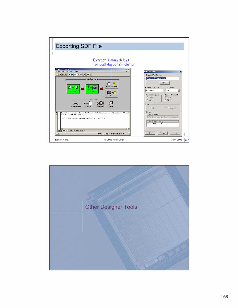
169
© 2005 Actel Corp. 337Libero™ IDE July, 2005
Exporting SDF File
Extract Timing delaysfor post-layout simulation
Other Designer Tools

170
© 2005 Actel Corp. 339Libero™ IDE July, 2005
SmartPower
SmartPower Supports Axcelerator, ProASIC, and ProASICPLUS
Families
� SmartPower Icon Not Visible for other Families
SmartPower Report Contains Clock Domains, Set of Pins, and Annotated Pins
� Detailed Information Available in Designer Documentation
� SmartPower.pdf
SmartPower icon
© 2005 Actel Corp. 340Libero™ IDE July, 2005
SmartPowerSummary Tab
� Total Static and Dynamic Power of Design
� Calculates Junction Temperature for Given Cooling Scenario
Design LevelPower Summary
Calculated Junction Temp.Cooling Type
Ambient Temp.

171
© 2005 Actel Corp. 341Libero™ IDE July, 2005
SmartPowerDomains Tab
� Shows Clock Domains with their Corresponding Frequencies
Filter Boxes
Create New Domain
Delete selected domain
Pin management window -add pin to the current domain.
Domain management window –add domains or select an existing domain
© 2005 Actel Corp. 342Libero™ IDE July, 2005
SmartPowerDynamic Tab
� Provides Detailed Hierarchical Reports of Dynamic Power Consumption
ReportedValues
ReportWindow
Hierarchy Instances Window

172
© 2005 Actel Corp. 343Libero™ IDE July, 2005
SmartPowerActivity Tab
� Allows Entry of Switching Activity Information on Interconnects of Design
Annotated Pins
Selected Clock Domain
Non-Annotated Pins
Specified Frequency
Pin Type
Global Frequency
© 2005 Actel Corp. 344Libero™ IDE July, 2005
SmartPowerPower Report
� Text Format
� Select Hierarchical, Flat or Breakdown as Report Style
� Select Static and/or Dynamic Power for Reporting
� Options Menu Invokes Preferences Menu

173
© 2005 Actel Corp. 345Libero™ IDE July, 2005
Post-Layout Simulation
Post-Synthesis Simulation
Design Capture
Synthesis
Programming
Simulation
Place & Route
Post-P&R Simulation
© 2005 Actel Corp. 346Libero™ IDE July, 2005
Post-Layout Simulation
� Steps
� Route design
� Export .sdf file (Back-annotate)
� Run Post-layout Simulation
� SDF File Contains Delays for Min, Typ and Max
(DELAYFILE
(SDFVERSION "2.1")
(DESIGN "counter")
(VOLTAGE 2.70:2.50:2.30)
(PROCESS "WORST")
(TEMPERATURE 0:25:70)
(TIMESCALE 100ps)
(CELL
(CELLTYPE "OUTBUF")
(INSTANCE COUNT_pad_12)
(DELAY
(ABSOLUTE
(PORT D (1.65:2.55:3.52) (2.21:3.40:4.62))
(IOPATH D PAD (19.19:28.90:39.88) (17.49:26.35:38.85))
)
)
)
rising min:typ:max
falling min:typ:max

174
© 2005 Actel Corp. 347Libero™ IDE July, 2005
Post-Layout Simulation
� Click on “Simulation” in Design Flow Window or…
Right
Mouse
Click!
Double
Click!
© 2005 Actel Corp. 348Libero™ IDE July, 2005
Post-Layout Simulation
� Structural Netlist and .sdf File Used for Simulation
� Simulator runs for 1 uS as Default
� Max Operating Conditions Default

175
© 2005 Actel Corp. 349Libero™ IDE July, 2005
Post-Layout SimulationSelecting Operating Conditions
� Post-layout Operating Conditions Can Be Specified within Libero
� Tools > Options from Libero Main Window
� Select Simulation Tab in Options Window
� Choose Min/Typ/Max
© 2005 Actel Corp. 350Libero™ IDE July, 2005
Programming & Debugging
Post-Synthesis Simulation
Design Capture
SynthesisSimulation
Place & Route
ProgrammingPost-P&R Simulation

176
© 2005 Actel Corp. 351Libero™ IDE July, 2005
Generating Programming FileFlash
Generate programming file (bitstream or STAPL)
Select output file type
File Format Contains ProgrammerBitstream Raw Data Sculptor, Sculptor II
STAPL
Raw Data plus programming infomration
Sculptor, Sculptor II, FlashPro, FlashPro Lite, In system programming
© 2005 Actel Corp. 352Libero™ IDE July, 2005
Sculptor II Overview
� PC-based Parallel-port, Single Device Programmer
� Designed to Allow Concurrent Programming of Multiple Units from Same PC
� Replaces Silicon Sculptor I as Actel's Programmer of Choice
� Silicon Sculptor II Benefits:
� Programs All Actel Packages
� Antifuse and Flash Programming Support
� Universal Actel Socket Adapters
� Works with Silicon Sculptor I Adapter Modules
� Uses Same Software as Silicon Sculptor I
� Provides Extensive Self-test Capability
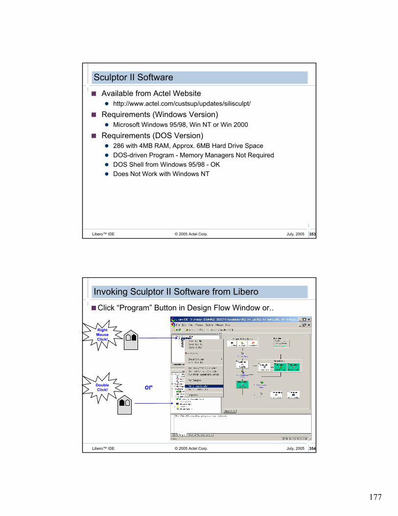
177
© 2005 Actel Corp. 353Libero™ IDE July, 2005
� Available from Actel Website
� http://www.actel.com/custsup/updates/silisculpt/
� Requirements (Windows Version)
� Microsoft Windows 95/98, Win NT or Win 2000
� Requirements (DOS Version)
� 286 with 4MB RAM, Approx. 6MB Hard Drive Space
� DOS-driven Program - Memory Managers Not Required
� DOS Shell from Windows 95/98 - OK
� Does Not Work with Windows NT
Sculptor II Software
© 2005 Actel Corp. 354Libero™ IDE July, 2005
Invoking Sculptor II Software from Libero
�Click “Program” Button in Design Flow Window or..
or
Right
Mouse
Click!
Double
Click!

178
© 2005 Actel Corp. 355Libero™ IDE July, 2005
1. Select > Device2. Buffer > Load
Checksum Command (under the pull down menu) compares checksum on the chip to FUSCHECKSUM in the .afm file.
Programs the design fuses.
Programs the security fuse.
Status Area
Check to see if the chip is blank.
Silicon Sculptor II Windows Interface
© 2005 Actel Corp. 356Libero™ IDE July, 2005
Silicon Sculptor II DOS Interface
1. Select > Device
2. Buffer > LoadCompares checksum on the chip to
FUSCHECKSUM in the .afm file.
Checks to see if the chip is blank.
Programs the design fuses.
Programs the security fuse.
Status Area

179
© 2005 Actel Corp. 357Libero™ IDE July, 2005
Flash Programming
� Flash FPGA Devices Can Be Programmed Multiple Ways
� Off-board Programming with Silicon Sculptor II
� In-System Programming (ISP) using JTAG Interface with Silicon Sculptor II, Flash Pro or Flash Pro Lite Portable Programmer
� Programming via Microprocessor Interface (ProASICPLUS)
© 2005 Actel Corp. 358Libero™ IDE July, 2005
FlashPro Programmer
� Supports All Flash FPGAs
� Small Form Factor - 24 in3
� Low Cost
� Hardware Features
� Small 26-pin Header
� 20” Ribbon Cable
� ECP Parallel Port
� Software Features
� Win 95/98/NT/00 O/S
� STAPL Support
� Daisy Chain Capability
� Log File Generation
� Self-test Option

180
© 2005 Actel Corp. 359Libero™ IDE July, 2005
FlashPro Lite Programmer
� Supports ProASICPLUS Devices
� Low Cost
� Ultra-small Form Factor
� Hardware Features
� Draws Power from Target Board
� Connects to Parallel Port
� Supports In-system Programming
� Software Features
� Supports Windows 98, NT, 2000, and XP Operating Systems
� STAPL Support
� Free Software Updates
© 2005 Actel Corp. 360Libero™ IDE July, 2005
� New Header
� Samtec 26-pin Header
� Support by Flash Pro and Silicon Sculptor
� Part Number: FTSH-113-01-L-D-K
� Pinout (on Customer PCB Board, Top View)
1 2
3 4
5 6
7 8
9 10
11 12
13 14
15 16
17 18
19 20
21 22
23 24
25 26
VDDP
VDDP
VPP
VPN
GND
TCK
TDI
TDO
TMS
RCK
TRSTB
VDDL/VDD
VDDLVDD
2.5/3.3V
2.5V/3.3V
2.5V/3.3V
GND
GND
GND
NC
NC
GND
GND
TRSTB
2.5V
2.5V
ISP for ProASICPLUS Programming Header

181
© 2005 Actel Corp. 361Libero™ IDE July, 2005
FlashPro User Interface
© 2005 Actel Corp. 362Libero™ IDE July, 2005
Programming with FlashPro
� Launch FlashPro from Libero
� Connect to Programmer
� Analyze Chain
� Select Device and Operation
� Execute Operation
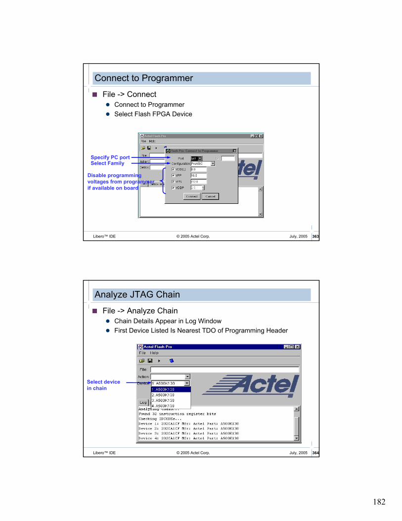
182
© 2005 Actel Corp. 363Libero™ IDE July, 2005
Connect to Programmer
� File -> Connect
� Connect to Programmer
� Select Flash FPGA Device
Specify PC portSelect Family
Disable programming
voltages from programmer
if available on board
© 2005 Actel Corp. 364Libero™ IDE July, 2005
Analyze JTAG Chain
� File -> Analyze Chain
� Chain Details Appear in Log Window
� First Device Listed Is Nearest TDO of Programming Header
Select device
in chain

183
© 2005 Actel Corp. 365Libero™ IDE July, 2005
Load STAPL File
� Load STAPL File for Programming
� STAPL File Exported from Designer
Open file
© 2005 Actel Corp. 366Libero™ IDE July, 2005
Selecting an Operation
� Select Action to Perform
Option ActionProgram Programs device
Erase Erases device
VerifyVerify device (same as VERIFY_EOL)
Verify BOLVerify all flash cells within BOL spec
Verify EOLVerify all flash cells within EOL spec
READ_IDCODE Reads device ID
READ Reads back device
DEVICE_INFOReturns device type and s/n
CHECK Checks device id

184
© 2005 Actel Corp. 367Libero™ IDE July, 2005
Execute Operation
Execute button
Programming sequence
Optional steps in bold font
Progress displayed
in log window
© 2005 Actel Corp. 368Libero™ IDE July, 2005
Invoking FlashPro Software from Libero
� Click “Program” Button in Design Flow Window or..
or
Right
Mouse
Click!
Double
Click!

185
© 2005 Actel Corp. 369Libero™ IDE July, 2005
Programmer Summary
ProgrammerSupported Families Manufacturer Connection
Sculptor II ALL BP Microsystems PC Parallel
Flash Pro
ProASIC and
ProASICPLUS
FS2 PC Parallel
Flash Pro Lite ProASICPLUS
FS2 PC Parallel

186
© 2005 Actel Corp. 371Libero™ IDE July, 2005
Silicon Explorer
� Debug Designs in Real Time!
� Select Internal FPGA Nodes on the Fly for Viewing while Device Runs at FULL Speed!
� Reduce Debug Time and Decrease your Time to Market!
Design
Prototype
Select Nodes
ObserveResults
Debug
© 2005 Actel Corp. 372Libero™ IDE July, 2005
Preparing for Debug
� If Possible, Avoid Using Probe Pins for Regular User I/O
� Make Probe Pins Accessible
� Jumper Leads, Dedicated Connector
Reserve Probe pins during compilation

187
© 2005 Actel Corp. 373Libero™ IDE July, 2005
Preparing for Debug (cont.)
� Silicon Explorer Used for Debugging
� Can Probe any Two INTERNAL Nodes in Real Time
� Four Internal Nodes for Axcelerator
� Also Functions as 18-channel Logic Analyzer
� Needs Only .prb File to Allow Debugging.
� Security Fuse Should NOT Be Programmed on Device
Generate Probe file
© 2005 Actel Corp. 374Libero™ IDE July, 2005
Action Probe Circuitry
� Dynamic Internal Node Access
� No Changes to Timing Relationships
� No Changes to Fan-out or Node Loading
� Patented Architectural Feature
� Antifuse Devices Only
� Unique to Actel
� No Silicon Overhead
� Uses Zero Logic Resources
� Always there if Needed
Control
Registers
Reg
iste
rs

188
© 2005 Actel Corp. 375Libero™ IDE July, 2005
Silicon Explorer SetupSX/SX-A/eX
SiliconExplorer
SerialConnection SX/SXA
TMSTDITCK D Q
PRB
PRA
TDO
18 Logic AnalyzerChannelsWindows PC
© 2005 Actel Corp. 376Libero™ IDE July, 2005
Silicon Explorer II
� Action Probe Control
� Serial Port Connection� No Plug-in Cards
� High-speed Signal Acquisition
� Sampling Rate� 100MHz Asynchronous
� 66 MHz Synchronous
� Analyze PC-hosted Software
� Optional External Power Supply (Recommended for SX-A)
� Multilevel Triggering

189
© 2005 Actel Corp. 377Libero™ IDE July, 2005
Silicon Explorer Software
� Flexible Signal Assignment
� Signal Grouping, Bussing
� Decimal, Hex, Binary, Analog Radix Selection for Bussed Signals
� Edge and Level Trigger Selection
� 64K Samples per Channel
� Easy-to-learn, Easy-to-use Interface
Full-featured 18 channel Logic Analyzer
© 2005 Actel Corp. 378Libero™ IDE July, 2005
Designer Cross-Probing
� Designer Allows you to Verify and Optimize your Design
� Silicon Explorer II Helps you Perform In-system Debugging
� Cross-Probing Links All Design Views

190
© 2005 Actel Corp. 379Libero™ IDE July, 2005
Invoking Silicon Explorer
� Launch Silicon Explorer from Toolbar or Process Window
Select
from
menu
Double
Click!
or
© 2005 Actel Corp. 380Libero™ IDE July, 2005
Summary
�Libero FPGA Design Suite Includes:� Design Entry
� ViewDraw, HDL Editor, ACTgen
� Synthesis� Synplicity
� Physical Synthesis� Magma PALACE
� Verification� ModelSim, WaveFormer Lite
� Designer (P&R, Timing Analysis and Constraints)
�Actel Continues to Improve Libero IDE� Increased Quality of Results
� Ease of Use
� Additional Features