Embed Size (px)
Citation preview

LECTURE 9 Pipeline Hazards

PIPELINED DATAPATH AND CONTROL
In the previous lecture, we finalized the pipelined datapath for instruction sequences which do not include hazards of any kind.
Remember that we have two kinds of hazards to worry about:
• Data hazards: an instruction is unable to execute in the planned cycle because it is dependent on some data that has not yet been committed.
sub $s0, $s1, $s2 # $s0 written in cycle 5add $s3, $s0, $s4 # $s0 read in cycle 3
• Control hazards: we do not know which instruction needs to be executed next.
beq $t0, $t1, L1 # target in cycle 3 add $t0, $t0, 1 # loaded in cycle 2
L1: sub $t0, $t0, 1

DATA HAZARDS
Let us now turn our attention to data hazards. As we’ve already seen, we have two solutions for data hazards:
• Forwarding (or bypassing): the needed data is forwarded as soon as possible to the instruction which depends on it.
• Stalling: the dependent instruction is “pushed back” for one or more clock cycles. Alternatively, you can think of stalling as the execution of a noop for one or more cycles.

DATA HAZARDS
Let’s take a look at the following instruction sequence.
We have a number of dependencies here. The last four instructions, which read register $2, are all dependent on the first instruction, which writes a value to register $2. Let’s naively pipeline these instructions and see what happens.
sub $2, $1, $3
and $12, $2, $5
or $13, $6, $2
add $14, $2, $2
sw $15, 100($2)

DATA HAZARDS
The blue lines indicate the data dependencies.
We can notice immediately that we have a problem.
The last four instructions require the register value to be -20 (the value during the WB stage of the first instruction).However, the middle three instructions will read the value to be 10 if we do not intervene.

DATA HAZARDS
We can resolve the last potentialhazard in our design of the register file unit.
Instruction 1 is writing the valueof $2 to the register file in the same cycle that instruction 4 is reading the value of $2.
We assume that the writeoperation takes place in the firsthalf of the clock cycle, while the read operation takes place in the second half. Therefore, the updated $2 value is available.

DATA HAZARDS
So the only data hazards occurfor instructions 2 and 3.
In this style of representation, we can easily identify true datahazards as they are the only oneswhose dependency lines go back in time.
Note that instruction 2 reads $2in cycle 3 and instruction 3 reads$2 in cycle 4.

DATA HAZARDS
Luckily instruction 1 calculates thenew values in cycle 3.
If we simply forward the data assoon as it is calculated, then wewill have it in time for the subsequent instructions to execute.

DATA HAZARDS
Let’s now take a look at how forwarding actually works.
First, we’ll introduce some new notation. To specify the name of a particular field in a particular pipeline register, we will use the following:
PipelineRegister.FieldName
So, for example, the number of the register corresponding to Read Data 2 from the register file in the ID/EX register is identifiable as ID/EX.RegisterRt.

DATA HAZARDS
We’re only going to worry about the challenge of forwarding data to be used in the EX stage.
The only writeable values that may be used in the EX stage arethe contents of the $rs and $rtregisters.
It’s ok if we read the wrong valuesfrom the register file, but we needto make sure the right values are used as input to the ALU!
DATA HAZARDS
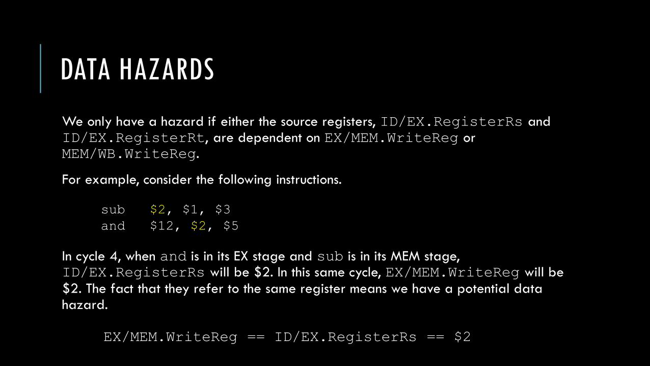
We only have a hazard if either the source registers, ID/EX.RegisterRs and ID/EX.RegisterRt, are dependent on EX/MEM.WriteReg or MEM/WB.WriteReg.
For example, consider the following instructions.
In cycle 4, when and is in its EX stage and sub is in its MEM stage, ID/EX.RegisterRs will be $2. In this same cycle, EX/MEM.WriteReg will be
$2. The fact that they refer to the same register means we have a potential data hazard.
EX/MEM.WriteReg == ID/EX.RegisterRs == $2
sub $2, $1, $3
and $12, $2, $5
DATA HAZARDS
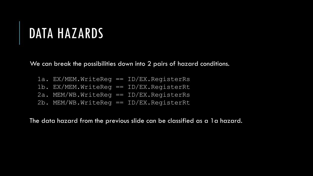
We can break the possibilities down into 2 pairs of hazard conditions.
The data hazard from the previous slide can be classified as a 1a hazard.
1a. EX/MEM.WriteReg == ID/EX.RegisterRs
1b. EX/MEM.WriteReg == ID/EX.RegisterRt
2a. MEM/WB.WriteReg == ID/EX.RegisterRs
2b. MEM/WB.WriteReg == ID/EX.RegisterRt

DATA HAZARDS
Classify the hazards in this sequence of instructions.
sub $2, $1, $3
and $12, $5, $2
or $13, $2, $6
add $14, $2, $2
sw $15, 100($2)
1a. EX/MEM.WriteReg == ID/EX.RegisterRs
1b. EX/MEM.WriteReg == ID/EX.RegisterRt
2a. MEM/WB.WriteReg == ID/EX.RegisterRs
2b. MEM/WB.WriteReg == ID/EX.RegisterRt

DATA HAZARDS
Classify the hazards in this sequence of instructions.
sub $2, $1, $3
and $12, $5, $2 # 1b
or $13, $2, $6 # 2a
add $14, $2, $2 # No hazard
sw $15, 100($2) # No hazard
1a. EX/MEM.WriteReg == ID/EX.RegisterRs
1b. EX/MEM.WriteReg == ID/EX.RegisterRt
2a. MEM/WB.WriteReg == ID/EX.RegisterRs
2b. MEM/WB.WriteReg == ID/EX.RegisterRt

DATA HAZARDS
The naïve solution would be to suggest that if any of the following hazards are detected, we should perform forwarding.
However, not all instructions perform register writes. So, we add the following requirement to our policy: the RegWrite signal must be asserted in the WB control field during the EX stage for type 1 hazards and the MEM stage for type 2 hazards.
1a. EX/MEM.WriteReg == ID/EX.RegisterRs
1b. EX/MEM.WriteReg == ID/EX.RegisterRt
2a. MEM/WB.WriteReg == ID/EX.RegisterRs
2b. MEM/WB.WriteReg == ID/EX.RegisterRt

DATA HAZARDS
Also, we do not allow results to be written to the $0 register so, in the event that an instruction uses $0 as its destination (which is legal), we should not forward the result (because it won’t even be written back to the register file anyway).
This gives us two additional conditions:
• EX/MEM.WriteReg != 0
• MEM/WB.WriteReg != 0

DATA HAZARDS
To summarize, we have an EX hazard if either of the following are true:
1a. EX/MEM.RegWrite && EX/MEM.WriteReg != 0 &&
EX/MEM.WriteReg == ID/EX.RegisterRs
1b. EX/MEM.RegWrite && EX/MEM.WriteReg != 0 &&
EX/MEM.WriteReg == ID/EX.RegisterRt

DATA HAZARDS
To summarize, we have an MEM hazard if either of the following are true:
2a. MEM/WB.RegWrite && MEM/WB.WriteReg != 0 &&
MEM/WB.WriteReg == ID/EX.RegisterRs
2b. MEM/WB.RegWrite && MEM/WB.WriteReg != 0 &&
MEM/WB.WriteReg == ID/EX.RegisterRt

DATA HAZARDS
So far, we have only defined the conditions for detecting data hazards. We have not yet implemented forwarding so let’s do that now.
Note the change in our dependency diagram. Now, we can see that the inputs to the ALU are dependent on pipeline registers rather than the results of the WB stage.

DATA HAZARDS
Forwarding works by allowing us to grab the inputs of the ALU not only from the ID/EX pipeline register, but from any other pipeline register.

DATA HAZARDS
Here is a close-up of our naïve pipelined datapathwhich has no support for forwarding.

DATA HAZARDS
And now with forwarding!
Instead of directly pipingthe ID/EX pipeline registervalues into the ALU, we now have multiplexors that allow us to choose where the input should come from. EX/MEM.WriteReg
MEM/WB.WriteReg

DATA HAZARDS
Note that we now forwardnot only the data of the the Read Data 1 and ReadData 2 fields from the previous cycle but alsothe numbers of those registers.
EX/MEM.WriteReg
MEM/WB.WriteReg

DATA HAZARDS
Given this pipeline, we can now formulate a policy for the forwarding unit.
In the following slides, we will define the control signals produced by the forwarding unit given the conditions we worked out earlier.

DATA HAZARDS
We can resolve EX hazards in the following way:
1a. if(EX/MEM.RegWrite && EX/MEM.WriteReg != 0 &&
EX/MEM.WriteReg == ID/EX.RegisterRs) ForwardA = 10
1b. if(EX/MEM.RegWrite && EX/MEM.WriteReg != 0 &&
EX/MEM.WriteReg == ID/EX.RegisterRt) ForwardB = 10

DATA HAZARDS
We can resolve MEM hazards in the following way:
2a. if(MEM/WB.RegWrite && MEM/WB.WriteReg != 0 &&
MEM/WB.WriteReg == ID/EX.RegisterRs) ForwardA = 01
2b. if(MEM/WB.RegWrite && MEM/WB.WriteReg != 0 &&
MEM/WB.WriteReg == ID/EX.RegisterRt) ForwardB = 01

DATA HAZARDS
We have one last issue to resolve. Consider the following sequence of instructions. Assume we have resolved the first data hazard using forwarding.
The second data hazard is both a 1a and 2a data hazard. The EX/MEM.WriteReg and MEM/WB.WriteReg registers will be the same as the ID/EX.RegisterRS register in cycle 4. Also, all instructions are writing to the register file and none have a $0 destination. How should this be resolved?
add $1, $1, $2
add $1, $1, $3
add $1, $1, $4

DATA HAZARDS
We have one last issue to resolve. Consider the following sequence of instructions. Assume we have resolved the first data hazard using forwarding.
The second data hazard is both a 1a and 2a data hazard.
We want to forward the value from the second instruction, not the first! This is the only way to simulate synchronous execution. Generally, we should never resolve as if it’s a type 2 hazard if there is also a type 1 hazard for that source register.
add $1, $1, $2
add $1, $1, $3
add $1, $1, $4

DATA HAZARDS
We can resolve MEM hazards in the following updated way:
2a. if(MEM/WB.RegWrite && MEM/WB.WriteReg != 0 &&
MEM/WB.WriteReg == ID/EX.RegisterRs
&& !(EX/MEM.RegWrite && EX/MEM.WriteReg != 0 &&
EX/MEM.WriteReg == ID/EX.RegisterRs)) ForwardA = 01
2b. if(MEM/WB.RegWrite && MEM/WB.WriteReg != 0 &&
MEM/WB.WriteReg == ID/EX.RegisterRt
&& !(EX/MEM.RegWrite && EX/MEM.WriteReg != 0 &&
EX/MEM.WriteReg == ID/EX.RegisterRt)) ForwardB = 01
DATA HAZARDS
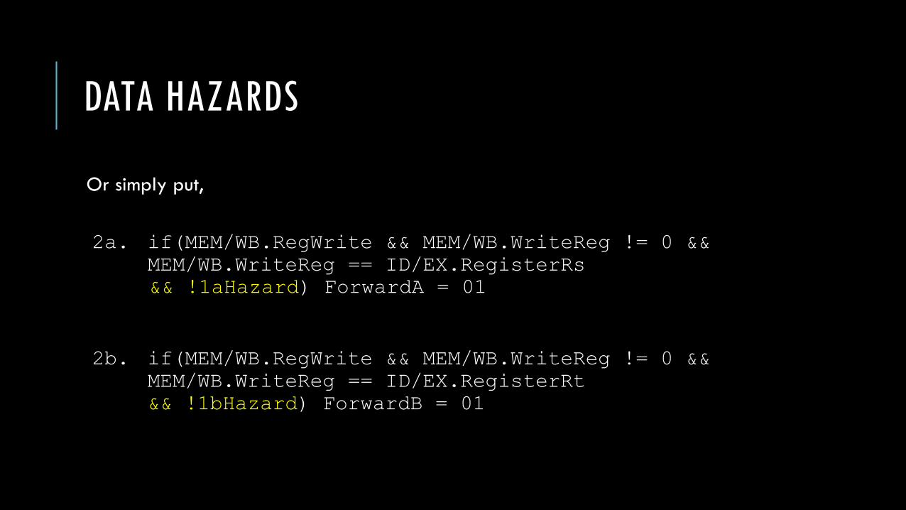
Or simply put,
2a. if(MEM/WB.RegWrite && MEM/WB.WriteReg != 0 &&
MEM/WB.WriteReg == ID/EX.RegisterRs
&& !1aHazard) ForwardA = 01
2b. if(MEM/WB.RegWrite && MEM/WB.WriteReg != 0 &&
MEM/WB.WriteReg == ID/EX.RegisterRt
&& !1bHazard) ForwardB = 01

DATAPATH/CONTROL WITH FORWARDING
EX/MEM.WriteReg
MEM/WB.WriteReg

FORWARDING UNIT CONTROL VALUES
Mux Control Source Explanation
ForwardA = 00 ID/EX First ALU input comes from register file.
ForwardA = 10 EX/MEM First ALU input is forwarded from the prior ALU result.
ForwardA = 01 MEM/WB First ALU input is forwarded from the data memory or a
prior ALU result.
ForwardB = 00 ID/EX Second ALU input comes from register file.
ForwardB = 10 EX/MEM Second ALU input is forwarded from the prior ALU
result.
ForwardB = 01 MEM/WB Second ALU input is forwarded from the data memory
or a prior ALU result.

DATAPATH/CONTROL WITH FORWARDING
As a correction to slide 30, note that we do need an additional multiplexor in front of the second ALUoperand in order to decidebetween the rt register contents and the sign-extimmediate value.
This may be omitted for now while we discuss data hazards.

DATA HAZARDS AND STALLING
Consider the following sequence of instructions.
Even with forwarding, our dependency from a load word instruction goes backward in time.
lw $2, 20($1)
and $4, $2, $5
or $8, $2, $6
add $9, $4, $2
slt $1, $6, $7

DATA HAZARDS AND STALLING
In the event that we have a load word instruction immediately followed by an instruction that reads its result, we must perform a stall.
We can do this by adding a hazard detection unit in the ID stage with the following condition:
if (ID/EX.MemRead &&
((ID/EX.RegisterRt == IF/ID.RegisterRs) ||
(ID/EX.RegisterRt == IF/ID.RegisterRt))) Stall the Pipeline
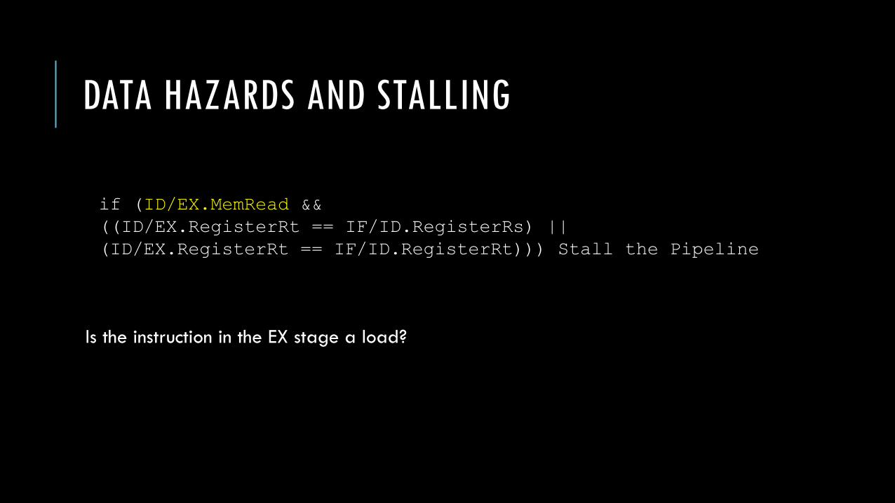
DATA HAZARDS AND STALLING
Is the instruction in the EX stage a load?
if (ID/EX.MemRead &&
((ID/EX.RegisterRt == IF/ID.RegisterRs) ||
(ID/EX.RegisterRt == IF/ID.RegisterRt))) Stall the Pipeline

DATA HAZARDS AND STALLING
Is the destination register of the load in the EX stage identical to either source register of the instruction in the ID stage?
if (ID/EX.MemRead &&
((ID/EX.RegisterRt == IF/ID.RegisterRs) ||
(ID/EX.RegisterRt == IF/ID.RegisterRt))) Stall the Pipeline

DATA HAZARDS AND STALLS
We implement stalls by basically inserting an instruction which does nothing. When, in the ID stage, we identify a need to perform a stall, we have the control unit output all nine control lines as 0’s.
These 0’s are forwarded through the datapath during subsequent clock cycles with the desired effect – they do nothing.
We also need the PC and IF/ID registers to remain unchanged so that we can ensure that the instruction scheduled for the current cycle will actually execute in the next cycle.

DATA HAZARDS AND STALLS

PIPELINED DATAPATH AND CONTROL
Note: sign-ext immediate
and branch logic are omitted
for simplification.

CONTROL HAZARDS
Now, we’ll turn our attention to control hazards. Let’s consider the following sequence of instructions:
When we execute these instructions on our pipelined datapath, we’ll see that the branch target is not written back to the PC until the 4th cycle.
beq $1, $3, 28
and $12, $2, $5
or $13, $6, $2
add $14, $2, $2
slt $15, $6, $7
…
lw $4, 50($7) # branch target
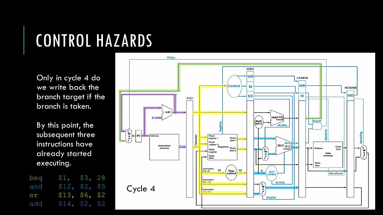
CONTROL HAZARDS
Only in cycle 4 dowe write back the branch target if thebranch is taken.
By this point, the subsequent three instructions have already started executing.
Cycle 4
beq $1, $3, 28
and $12, $2, $5
or $13, $6, $2
add $14, $2, $2

CONTROL HAZARDS
The simplest approach is to
always assume the branch isn’t taken.
Then the correct instructions will
already be executing anyway.
However, if we’re proven wrong in the
4th stage of the branch instruction, then
the other three instructions need to be
flushed from the datapath.
This is done by setting their control lines
to 0 when the reach the EX stage.
The next significant instruction will be
the branch target .

CONTROL HAZARDS
Another solution is to attempt to reduce the potential delay of a branch instruction.
Right now, because we only know the decision in the 4th stage, we have to gamble on three instructions which might have to be flushed if the branch is taken.
If we can move the decision to an earlier stage, then we can decrease the number of instructions we potentially need to flush.
To make the decision as early as possible, we need to move two actions:
• Calculation of the branch target address.
• Calculation of the branch decision.

CONTROL HAZARDS
Currently, we have these two actions taking place in the EX stage.
We can clearly move the branch target calculation up to the ID stage as all the required data is available at that time.
Cycle 4

CONTROL HAZARDS
The branch decision, however, relies on the Read Data 1 and Read Data 2 values read from the register file in the previous cycle.
Moving this step into the ID stage means that we also need to make sure the forwarded values of the operands are available. Cycle 4

CONTROL HAZARDS
Furthermore, because our branching instruction needs its forwarded values from previous instructions in the ID stage (as opposed to the EX stage), we may need to stall one or two cycles to wait for the forwarded data.
Cycle 4

CONTROL HAZARDS
Even with these difficulties, moving the branch prediction into the ID stage may be desirable because it reduces the penalty of a branch to one instruction instead of three instructions.
Consider the following instructions:
36 sub $10, $4, $8
40 beq $1, $3, 7
44 and $12, $2, $5
48 or $13, $2, $6
52 add $14, $4, $2
56 slt $15, $6, $7
…
72 lw $4, 50($7)
Imagine the numbers on the left represent the
addresses of the instructions.
What does beq do?
If the contents of $1 is equal to the contents of $3,
then we next execute the instruction given by:
(PC+4)+(7*4) = (40+4)+(28) = 44+28 = 72
So, if the branch is taken, we should execute the lw
instruction next.

36 sub $10, $4, $8
40 beq $1, $3, 7
44 and $12, $2, $5
48 or $13, $2, $6
52 add $14, $4, $2
56 slt $15, $6, $7
…
72 lw $4, 50($7)
Imagine we’re in cycle 3. In this
cycle, beq is in its ID stage.
We calculate the branch target
as well as the branch decision.
At the end of this cycle, if the
branch is taken, the address
72 is written to the PC to be
fetched in the next cycle.

36 sub $10, $4, $8
40 beq $1, $3, 7
44 and $12, $2, $5
48 or $13, $2, $6
52 add $14, $4, $2
56 slt $15, $6, $7
…
72 lw $4, 50($7)
Note that the details of
forwarding and hazard
detection have been largely
omitted here.
The idea is that we’ve added
two units – a dedicated adder
and dedicated equality tester –
to the ID stage to perform
branching earlier.

36 sub $10, $4, $8
40 beq $1, $3, 7
44 and $12, $2, $5
48 or $13, $2, $6
52 add $14, $4, $2
56 slt $15, $6, $7
…
72 lw $4, 50($7)
Now, the branch target will
start executing in cycle 4, but
we have already started
executing the and instruction.
We need to remove this from
the datapath. We’ll do this
by adding a new control to the
IF/ID register which is
responsible for zeroing out
its contents – creating a stall.

36 sub $10, $4, $8
40 beq $1, $3, 7
44 and $12, $2, $5
48 or $13, $2, $6
52 add $14, $4, $2
56 slt $15, $6, $7
…
72 lw $4, 50($7)
Here, we can see the state of
the datapath during cycle 4.

CONTROL HAZARDS
So, we’ve looked at two possible solutions:
• Assuming branch not taken.
• Easy to implement.
• High cost – three stalls if wrong.
• Performing branching in the ID stage.
• Harder to implement – must add forwarding and hazard control earlier.
• Lower cost – one stall if branch is taken.
We have another solution we can try: branch prediction.

CONTROL HAZARDS
In branch prediction, we attempt to predict the branching decisions and act accordingly.
When we assumed the branch wasn’t taken, we were making a simple static prediction. Luckily, the performance cost on a 5-stage pipeline is low but on a deeperpipeline with many more stages, that could be a huge performance cost!
In dynamic branch prediction, we look up the address of the instruction to see if the branch was taken last time. If so, we will predict that the branch will be taken again and optimistically fetch the instructions from the branch target rather than the subsequent instructions.

CONTROL HAZARDS
Here’s how the 1-bit branch prediction buffer works:
• Each element in the buffer contains a single bit indicating whether the branch prediction was taken last time.
• We make our prediction based on the bit found in the buffer.
• If the prediction turns out to be incorrect, then we flip the bit in the buffer and correct the pipeline.

CONTROL HAZARDS
A branch prediction buffer is a small memory indexed by the lower portion of the address of the branch instruction. The memory simply contains one bit indicating whether the branch was taken last time or not.
This isn’t a perfect scheme by any means. It’s just a simple mechanism that might give us a hint as to what the right decision might be. Note:
• The buffer is shared between branches with the same lower addresses. A buffer value may reflect another branch instruction.
• The branch instruction may simply make a different decision than it did before.

CONTROL HAZARDS
Consider a loop that branches nine times in a row, then is not taken once. What is the prediction accuracy for this branch, assuming the prediction bit for this branch remains in the prediction buffer?
int i = 0;
do{
/* loop body */
i = i + 1
}while(i < 10);
add $t0, $0, $0
L1: /* loop body*/
addi $t0, $t0, 1
slti $t1, $t0, 10
bne $t1, $0, L1
The prediction behavior will mispredict on both the first and last loop iterations. The last loop iteration
prediction happens because we’ve already taken the branch nine-times so far. The first loop iteration
happens because the bit was flipped on the last iteration of the previous execution. So, the prediction
accuracy is 80%.
CONTROL HAZARDS
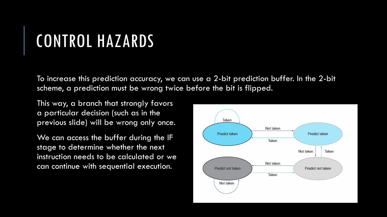
To increase this prediction accuracy, we can use a 2-bit prediction buffer. In the 2-bit scheme, a prediction must be wrong twice before the bit is flipped.
This way, a branch that strongly favorsa particular decision (such as in the previous slide) will be wrong only once.
We can access the buffer during the IF stage to determine whether the next instruction needs to be calculated or wecan continue with sequential execution.
CONTROL HAZARDS
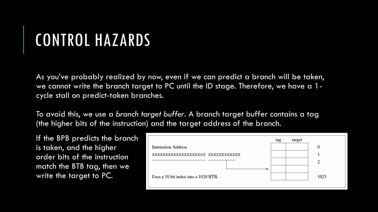
As you’ve probably realized by now, even if we can predict a branch will be taken, we cannot write the branch target to PC until the ID stage. Therefore, we have a 1-cycle stall on predict-taken branches.
To avoid this, we use a branch target buffer. A branch target buffer contains a tag (the higher bits of the instruction) and the target address of the branch.
If the BPB predicts the branchis taken, and the higherorder bits of the instruction match the BTB tag, then we write the target to PC.

FINAL DATAPATH AND CONTROL
Some details are omitted.
Notably the ALUSrc multiplexor
and multiplexor control lines are
omitted for simplicity.