Embed Size (px)
Citation preview
Spring 2005331 W11.1
14:332:331Computer Architecture and Assembly Language
Spring 2005
Week 11Introduction to Pipelined Datapath
[Adapted from Dave Patterson’s UCB CS152 slides and
Mary Jane Irwin’s PSU CSE331 slides]
Spring 2005331 W11.2
Head’s Up Reminders
Pipelined datapath and control HW#6 will be handed out soon
Spring 2005331 W11.3
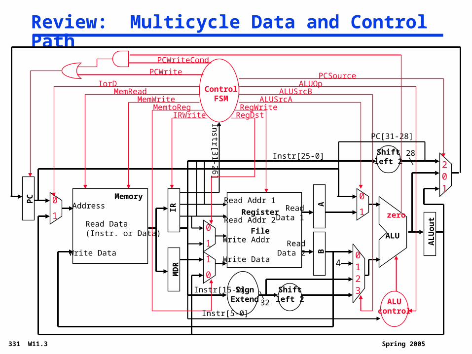
Review: Multicycle Data and Control Path
Address
Read Data(Instr. or Data)
Memory
PC
Write Data
Read Addr 1
Read Addr 2
Write Addr
Register
File
Read Data 1
Read Data 2
ALU
Write Data
IRM
DR
AB
AL
Uo
ut
SignExtend
Shiftleft 2 ALU
control
Shiftleft 2
ALUOpControl
FSM
IRWriteMemtoReg
MemWriteMemRead
IorD
PCWrite
PCWriteCond
RegDstRegWrite
ALUSrcAALUSrcB
zero
PCSource
1
1
1
1
1
10
0
0
0
0
0
2
2
3
4
Instr[5-0]
Instr[25-0]
PC[31-28]
Instr[15-0]
Instr[3
1-2
6]
32
28
Spring 2005331 W11.4
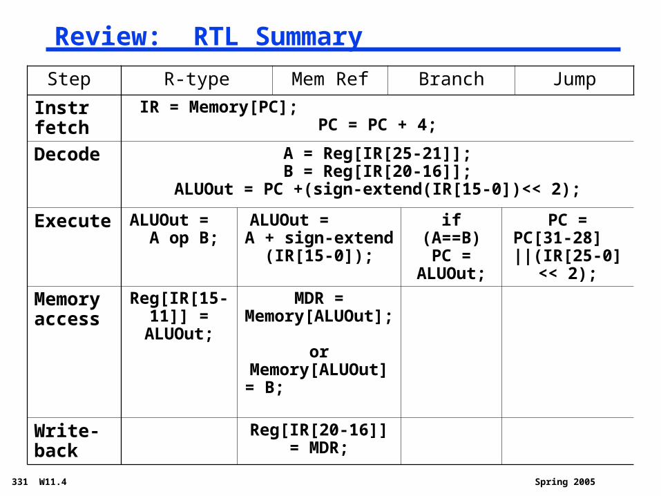
Review: RTL Summary
Step R-type Mem Ref Branch Jump
Instr fetch
IR = Memory[PC]; PC = PC + 4;
Decode A = Reg[IR[25-21]];B = Reg[IR[20-16]];
ALUOut = PC +(sign-extend(IR[15-0])<< 2);
Execute ALUOut = A op B;
ALUOut = A + sign-extend
(IR[15-0]);
if (A==B) PC =
ALUOut;
PC = PC[31-28] ||(IR[25-0]
<< 2);
Memory access
Reg[IR[15-11]] = ALUOut;
MDR = Memory[ALUOut];
orMemory[ALUOut] = B;
Write-back
Reg[IR[20-16]] = MDR;
Spring 2005331 W11.5
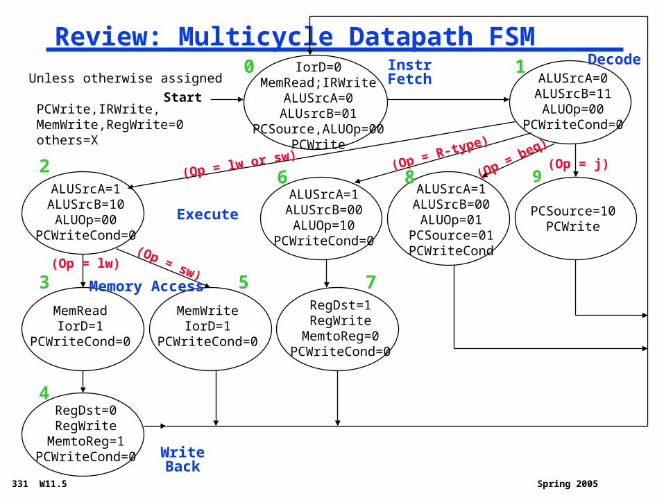
Review: Multicycle Datapath FSM
Start
Instr Fetch Decode
Write Back
Memory Access
Execute
(Op = R-
type)
(Op =
beq)
(Op = lw or
sw) (Op = j)
(Op = lw)(Op = sw)
0 1
2
3
4
5
6
7
8 9
Unless otherwise assigned
PCWrite,IRWrite, MemWrite,RegWrite=0 others=X
IorD=0MemRead;IRWrite
ALUSrcA=0ALUsrcB=01
PCSource,ALUOp=00PCWrite
ALUSrcA=0ALUSrcB=11ALUOp=00
PCWriteCond=0
ALUSrcA=1ALUSrcB=10ALUOp=00
PCWriteCond=0
ALUSrcA=1ALUSrcB=00ALUOp=10
PCWriteCond=0
ALUSrcA=1ALUSrcB=00ALUOp=01
PCSource=01PCWriteCond
PCSource=10PCWrite
MemReadIorD=1
PCWriteCond=0
MemWriteIorD=1
PCWriteCond=0
RegDst=1RegWriteMemtoReg=0
PCWriteCond=0
RegDst=0RegWriteMemtoReg=1
PCWriteCond=0
Spring 2005331 W11.6
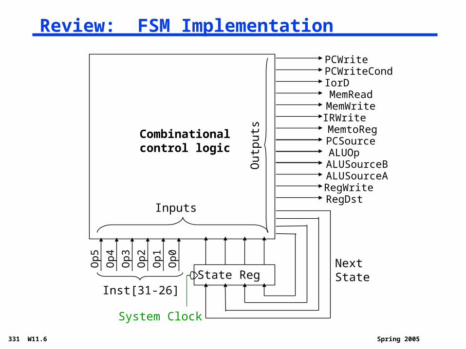
Review: FSM Implementation
Combinationalcontrol logic
State RegInst[31-26]
NextState
Inputs
Out
puts
Op0
Op1
Op2
Op3
Op4
Op5
PCWritePCWriteCondIorDMemReadMemWriteIRWriteMemtoRegPCSourceALUOpALUSourceBALUSourceARegWriteRegDst
System Clock
Spring 2005331 W11.7
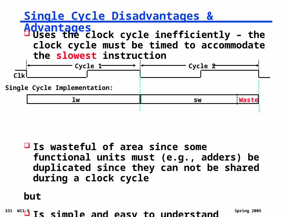
Single Cycle Disadvantages & Advantages
Uses the clock cycle inefficiently – the clock cycle must be timed to accommodate the slowest instruction
Is wasteful of area since some functional units must (e.g., adders) be duplicated since they can not be shared during a clock cycle
but
Is simple and easy to understand
Clk
Single Cycle Implementation:
lw sw Waste
Cycle 1 Cycle 2
Spring 2005331 W11.8
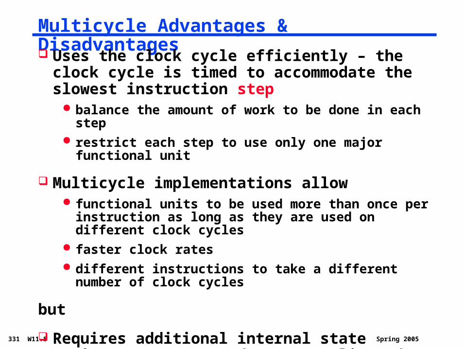
Multicycle Advantages & Disadvantages
Uses the clock cycle efficiently – the clock cycle is timed to accommodate the slowest instruction step
balance the amount of work to be done in each step restrict each step to use only one major functional unit
Multicycle implementations allow functional units to be used more than once per
instruction as long as they are used on different clock cycles
faster clock rates different instructions to take a different number of clock
cycles
but
Requires additional internal state registers, muxes, and more complicated (FSM) control
Spring 2005331 W11.9
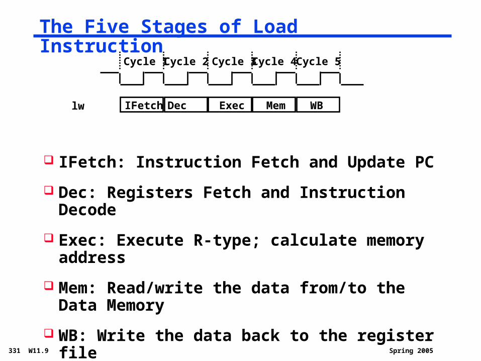
The Five Stages of Load Instruction
IFetch: Instruction Fetch and Update PC
Dec: Registers Fetch and Instruction Decode
Exec: Execute R-type; calculate memory address
Mem: Read/write the data from/to the Data Memory
WB: Write the data back to the register file
Cycle 1 Cycle 2 Cycle 3 Cycle 4 Cycle 5
IFetch Dec Exec Mem WBlw
Spring 2005331 W11.10
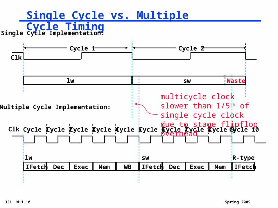
Single Cycle vs. Multiple Cycle Timing
Clk Cycle 1
Multiple Cycle Implementation:
IFetch Dec Exec Mem WB
Cycle 2 Cycle 3 Cycle 4 Cycle 5 Cycle 6 Cycle 7 Cycle 8 Cycle 9Cycle 10
IFetch Dec Exec Mem
lw sw
Clk
Single Cycle Implementation:
lw sw Waste
IFetch
R-type
Cycle 1 Cycle 2
multicycle clock slower than 1/5th of single cycle clock due to stage flipflop overhead
Spring 2005331 W11.11
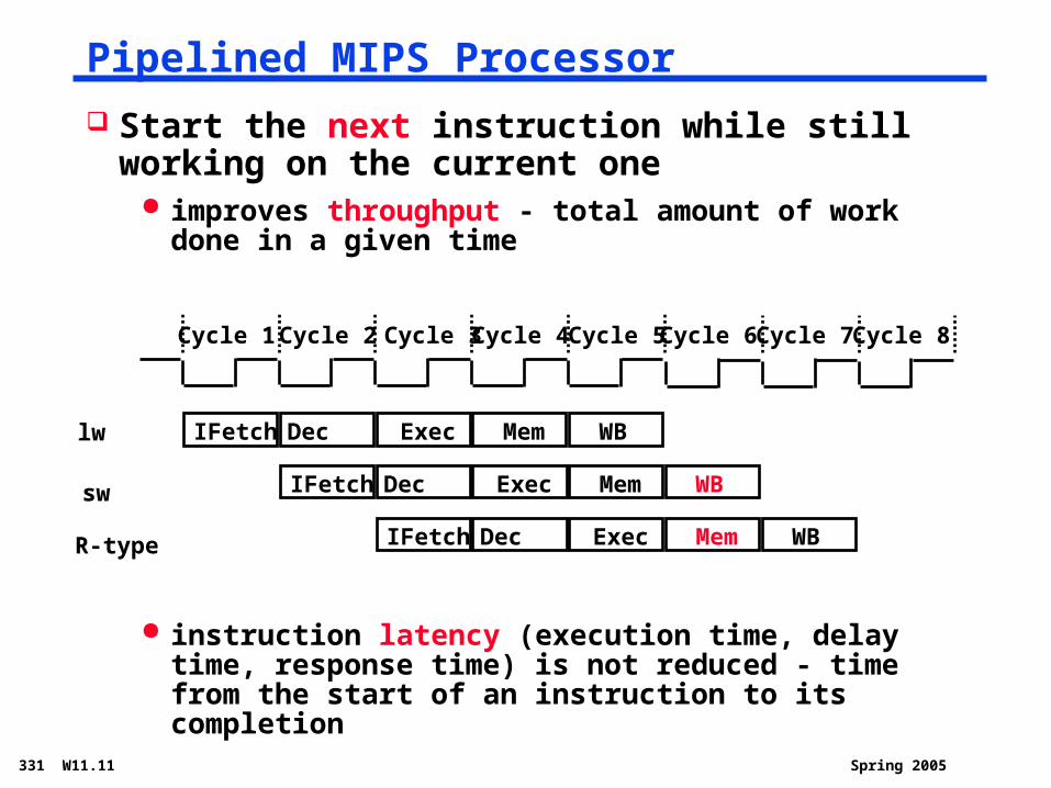
Pipelined MIPS Processor
Start the next instruction while still working on the current one
improves throughput - total amount of work done in a given time
instruction latency (execution time, delay time, response time) is not reduced - time from the start of an instruction to its completion
Cycle 1 Cycle 2 Cycle 3 Cycle 4 Cycle 5
IFetch Dec Exec Mem WBlw
Cycle 7Cycle 6 Cycle 8
sw IFetch Dec Exec Mem WB
R-type IFetch Dec Exec Mem WB
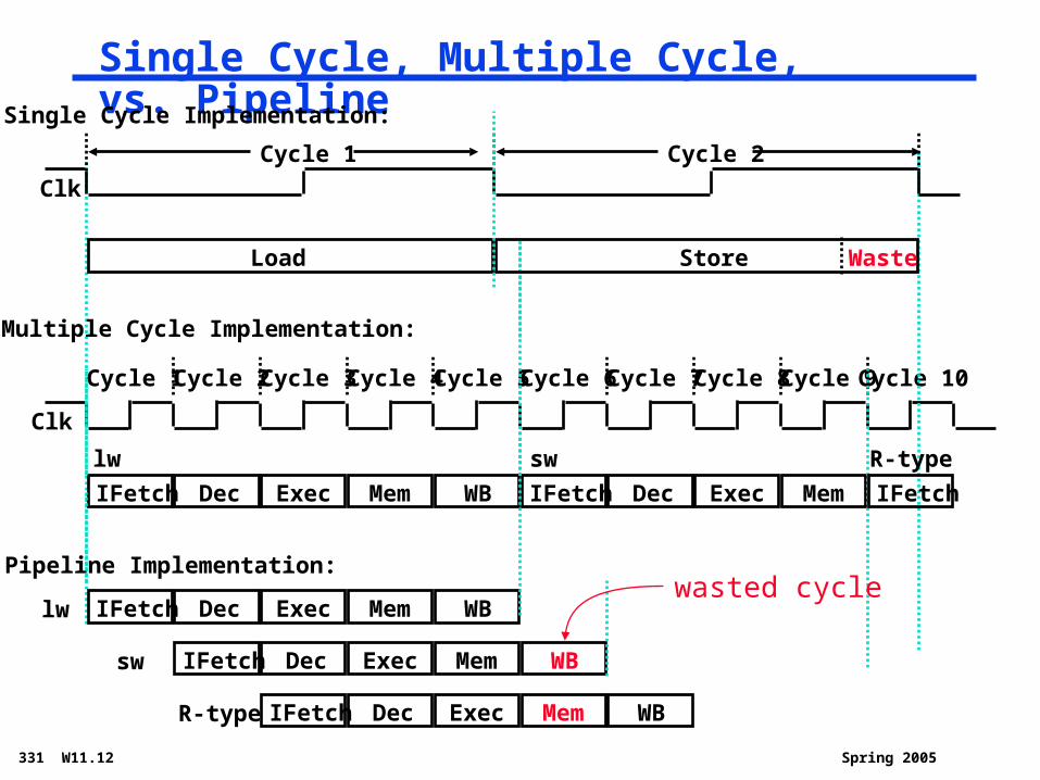
Spring 2005331 W11.12
Single Cycle, Multiple Cycle, vs. Pipeline
Clk
Cycle 1
Multiple Cycle Implementation:
IFetch Dec Exec Mem WB
Cycle 2 Cycle 3 Cycle 4 Cycle 5 Cycle 6 Cycle 7 Cycle 8 Cycle 9Cycle 10
lw IFetch Dec Exec Mem WB
IFetch Dec Exec Mem
lw sw
Pipeline Implementation:
IFetch Dec Exec Mem WBsw
Clk
Single Cycle Implementation:
Load Store Waste
IFetch
R-type
IFetch Dec Exec Mem WBR-type
Cycle 1 Cycle 2
wasted cycle
Spring 2005331 W11.13
Pipelining the MIPS ISA
What makes it easy all instructions are the same length (32 bits) few instruction formats (three) with symmetry across
formats memory operations can occur only in loads and stores operands must be aligned in memory so a single data
transfer requires only one memory access
What makes it hard structural hazards: what if we had only one memory control hazards: what about branches data hazards: what if an instruction’s input operands
depend on the output of a previous instruction
Spring 2005331 W11.14
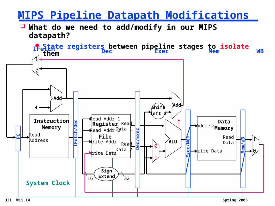
MIPS Pipeline Datapath Modifications
ReadAddress
InstructionMemory
Add
PC
4
0
1
Write Data
Read Addr 1
Read Addr 2
Write Addr
Register
File
Read Data 1
Read Data 2
16 32
ALU
1
0
Shiftleft 2
Add
DataMemoryAddress
Write Data
ReadData
1
0
What do we need to add/modify in our MIPS datapath? State registers between pipeline stages to isolate them
IFe
tch
/De
c
De
c/E
xe
c
Ex
ec
/Me
m
Me
m/W
B
IFetch Dec Exec Mem WB
System Clock
SignExtend
Spring 2005331 W11.15
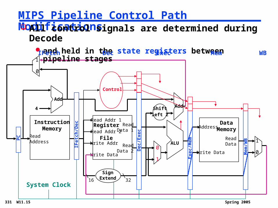
MIPS Pipeline Control Path Modifications
ReadAddress
InstructionMemory
Add
PC
4
0
1
Write Data
Read Addr 1
Read Addr 2
Write Addr
Register
File
Read Data 1
Read Data 2
16 32
ALU
1
0
Shiftleft 2
Add
DataMemoryAddress
Write Data
ReadData
1
0
All control signals are determined during Decode and held in the state registers between pipeline stages
IFe
tch
/De
c
De
c/E
xe
c
Ex
ec
/Me
m
Me
m/W
B
IFetch Dec Exec Mem WB
System Clock
Control
SignExtend
Spring 2005331 W11.16
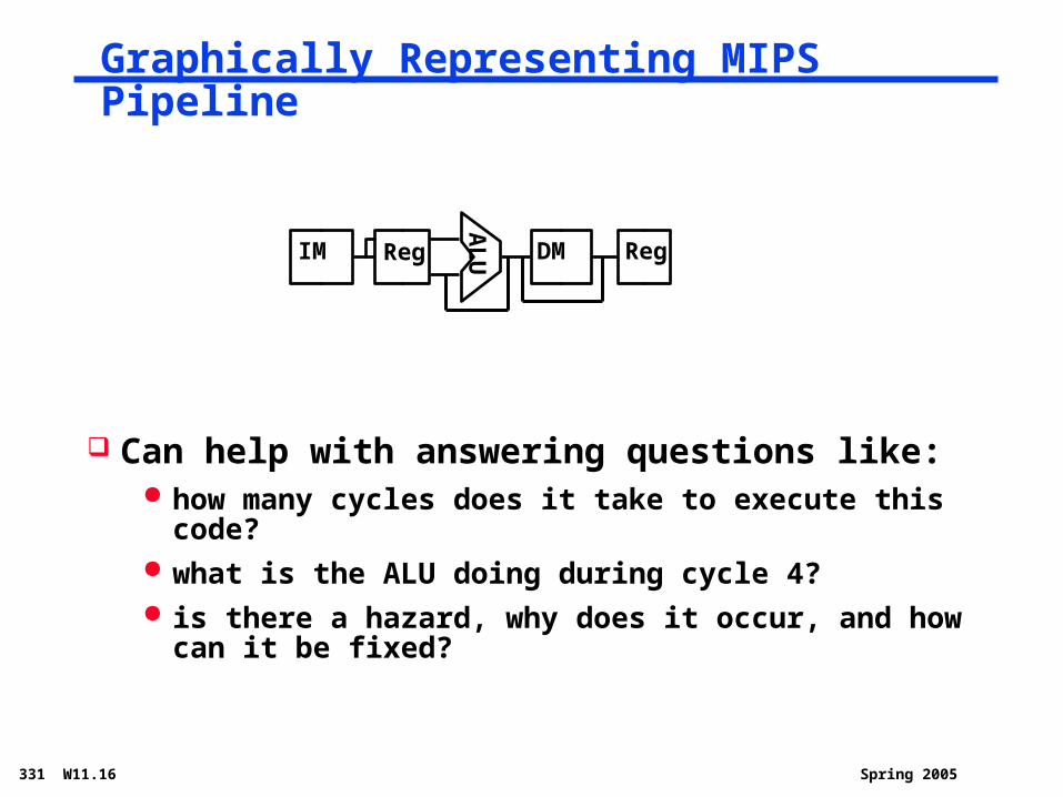
Graphically Representing MIPS Pipeline
Can help with answering questions like: how many cycles does it take to execute this code? what is the ALU doing during cycle 4? is there a hazard, why does it occur, and how can it be
fixed?A
LUIM Reg DM Reg
Spring 2005331 W11.17
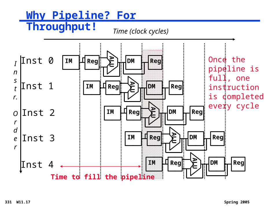
Why Pipeline? For Throughput!
Instr.
Order
Time (clock cycles)
Inst 0
Inst 1
Inst 2
Inst 4
Inst 3
AL
UIM Reg DM Reg
AL
UIM Reg DM Reg
AL
UIM Reg DM RegA
LUIM Reg DM Reg
AL
UIM Reg DM Reg
Once the pipeline is full, one instruction is completed every cycle
Time to fill the pipeline
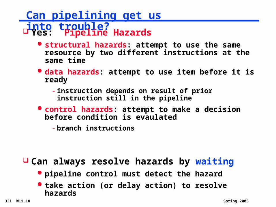
Spring 2005331 W11.18
Can pipelining get us into trouble? Yes: Pipeline Hazards
structural hazards: attempt to use the same resource by two different instructions at the same time
data hazards: attempt to use item before it is ready
- instruction depends on result of prior instruction still in the pipeline
control hazards: attempt to make a decision before condition is evaulated
- branch instructions
Can always resolve hazards by waiting pipeline control must detect the hazard take action (or delay action) to resolve hazards
Spring 2005331 W11.19
Instr.
Order
Time (clock cycles)
lw
Inst 1
Inst 2
Inst 4
Inst 3
AL
UMem Reg Mem Reg
AL
UMem Reg Mem Reg
AL
UMem Reg Mem RegA
LUMem Reg Mem Reg
AL
UMem Reg Mem Reg
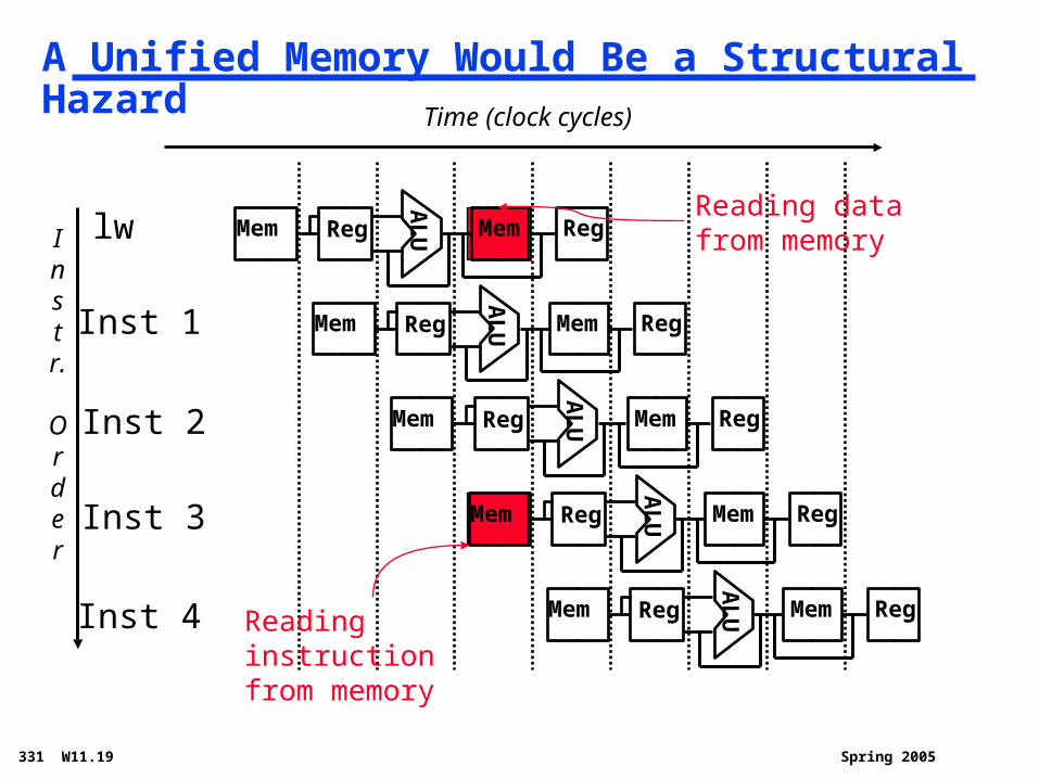
A Unified Memory Would Be a Structural Hazard
Reading data from memory
Reading instruction from memory
Spring 2005331 W11.20
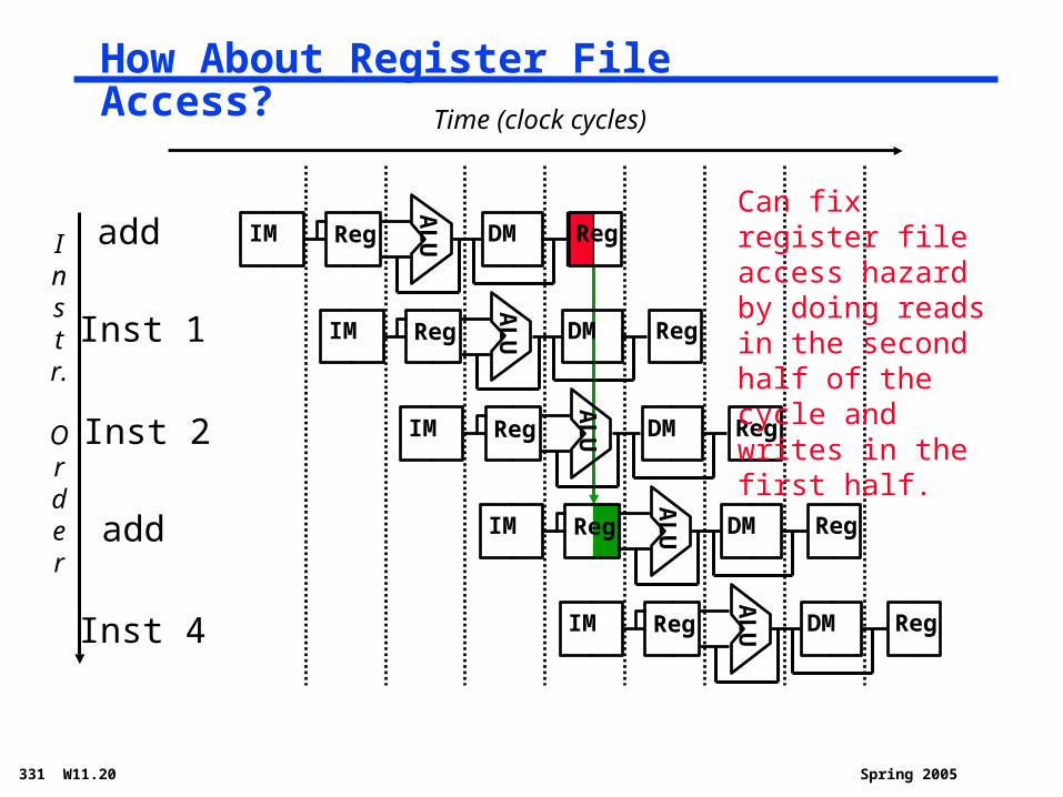
How About Register File Access?
Instr.
Order
Time (clock cycles)
add
Inst 1
Inst 2
Inst 4
add
AL
UIM Reg DM Reg
AL
UIM Reg DM Reg
AL
UIM Reg DM RegA
LUIM Reg DM Reg
AL
UIM Reg DM Reg
Can fix register file access hazard by doing reads in the second half of the cycle and writes in the first half.
Spring 2005331 W11.21
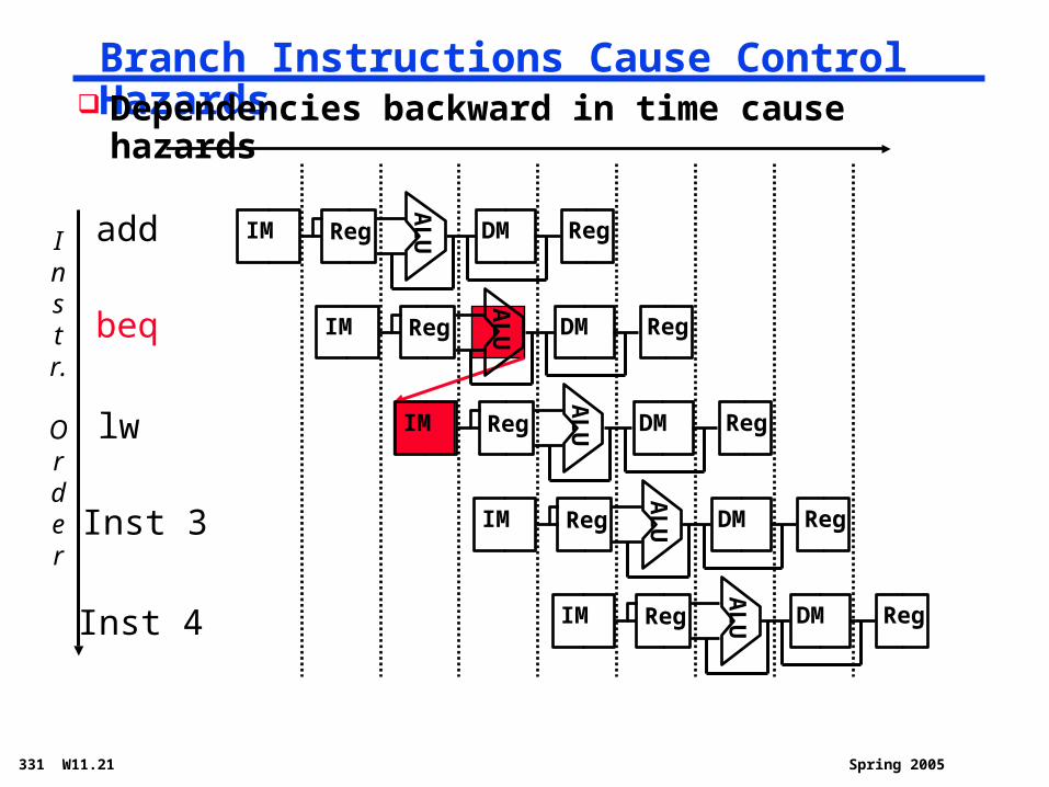
Branch Instructions Cause Control Hazards
Instr.
Order
add
beq
lw
Inst 4
Inst 3
AL
UIM Reg DM Reg
AL
UIM Reg DM Reg
AL
UIM Reg DM RegA
LUIM Reg DM Reg
AL
UIM Reg DM Reg
Dependencies backward in time cause hazards
Spring 2005331 W11.22
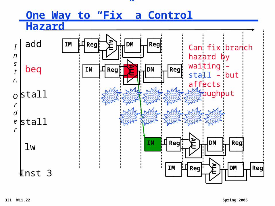
One Way to “Fix” a Control Hazard
Instr.
Order
add
beq
AL
UIM Reg DM Reg
AL
UIM Reg DM Reg
Inst 3
lw
AL
UIM Reg DM Reg
AL
UIM Reg DM Reg
Can fix branch hazard by waiting – stall – but affects throughput
stall
stall
Spring 2005331 W11.23
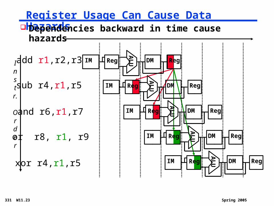
Register Usage Can Cause Data Hazards
Instr.
Order
add r1,r2,r3
sub r4,r1,r5
and r6,r1,r7
xor r4,r1,r5
or r8, r1, r9A
LUIM Reg DM Reg
AL
UIM Reg DM Reg
AL
UIM Reg DM Reg
AL
UIM Reg DM Reg
AL
UIM Reg DM Reg
Dependencies backward in time cause hazards
Spring 2005331 W11.24
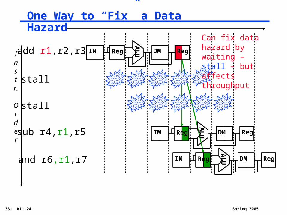
One Way to “Fix” a Data Hazard
Instr.
Order
add r1,r2,r3
AL
UIM Reg DM Reg
sub r4,r1,r5
and r6,r1,r7
AL
UIM Reg DM Reg
AL
UIM Reg DM Reg
stall
stall
Can fix data hazard by waiting – stall – but affects throughput

Spring 2005331 W11.25
Loads Can Cause Data Hazards
Instr.
Order
lw r1,100(r2)
sub r4,r1,r5
and r6,r1,r7
xor r4,r1,r5
or r8, r1, r9A
LUIM Reg DM Reg
AL
UIM Reg DM Reg
AL
UIM Reg DM Reg
AL
UIM Reg DM Reg
AL
UIM Reg DM Reg
Dependencies backward in time cause hazards
Spring 2005331 W11.26
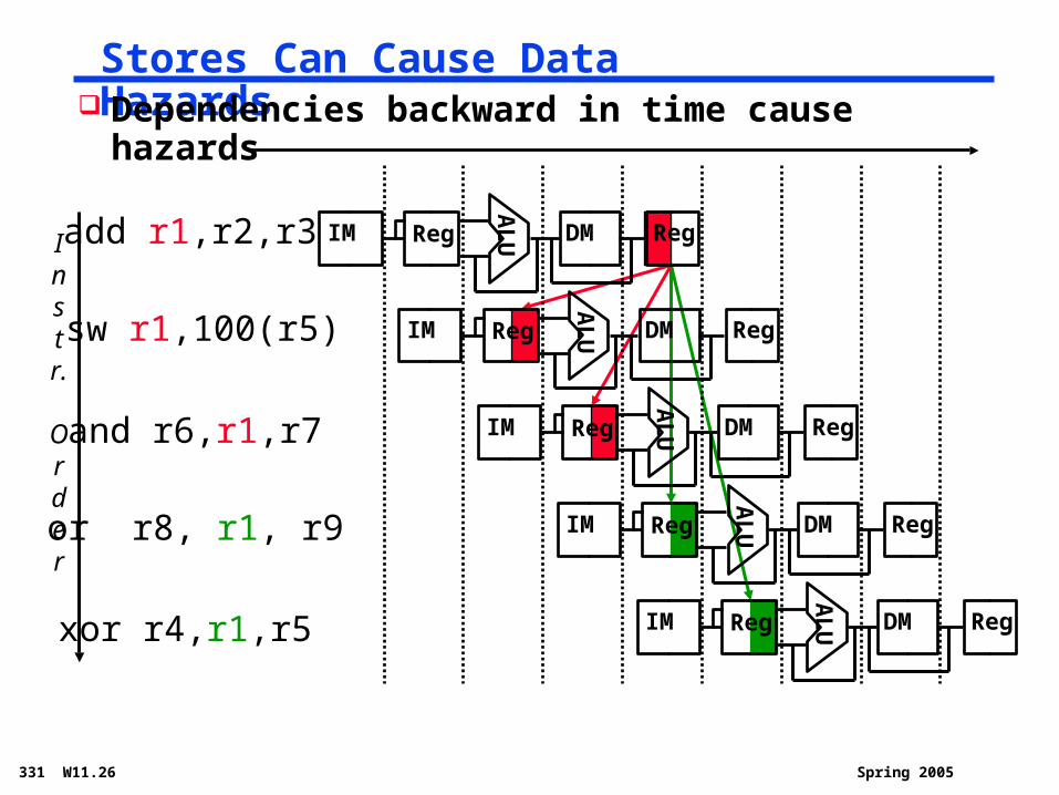
Stores Can Cause Data Hazards
Instr.
Order
add r1,r2,r3
sw r1,100(r5)
and r6,r1,r7
xor r4,r1,r5
or r8, r1, r9A
LUIM Reg DM Reg
AL
UIM Reg DM Reg
AL
UIM Reg DM Reg
AL
UIM Reg DM Reg
AL
UIM Reg DM Reg
Dependencies backward in time cause hazards
Spring 2005331 W11.27
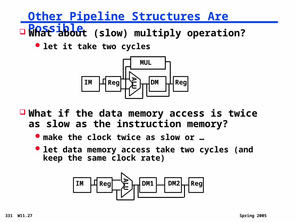
Other Pipeline Structures Are Possible What about (slow) multiply operation?
let it take two cycles
What if the data memory access is twice as slow as the instruction memory?
make the clock twice as slow or … let data memory access take two cycles (and keep the
same clock rate)A
LUIM Reg DM Reg
MUL
AL
UIM Reg DM1 RegDM2
Spring 2005331 W11.28
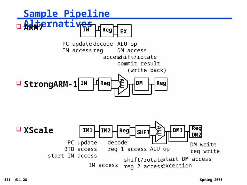
Sample Pipeline Alternatives ARM7
StrongARM-1
XScale
AL
UIM1 IM2 DM1 RegDM2
IM Reg EX
PC updateIM access
decodereg access
ALU opDM accessshift/rotatecommit result (write back)
AL
UIM Reg DM Reg
Reg SHFT
PC updateBTB access
start IM access
IM access
decodereg 1 access
shift/rotatereg 2 access
ALU op
start DM accessexception
DM writereg write
Spring 2005331 W11.29
Summary
All modern day processors use pipelining
Pipelining doesn’t help latency of single task, it helps throughput of entire workload
Multiple tasks operating simultaneously using different resources
Potential speedup = Number of pipe stages
Pipeline rate limited by slowest pipeline stage Unbalanced lengths of pipe stages reduces speedup Time to “fill” pipeline and time to “drain” it reduces
speedup
Must detect and resolve hazards Stalling negatively affects throughput

![CS35101 Computer Architecture Spring 2006 Week 8 P Durand (durand) [Adapted from MJI (mji)] [Adapted from Dave Patterson’s](https://img.pdfslide.us/doc/110x75/56649eab5503460f94bb0645/cs35101-computer-architecture-spring-2006-week-8-p-durand-wwwcskentedudurand.jpg)