Embed Size (px)
Citation preview
Lecture – 4Classical Control Overview – II
Dr. Radhakant PadhiAsst. Professor
Dept. of Aerospace EngineeringIndian Institute of Science - Bangalore
Stability Analysis through Transfer Function
Dr. Radhakant PadhiAsst. Professor
Dept. of Aerospace EngineeringIndian Institute of Science - Bangalore
ADVANCED CONTROL SYSTEM DESIGN Dr. Radhakant Padhi, AE Dept., IISc-Bangalore
3
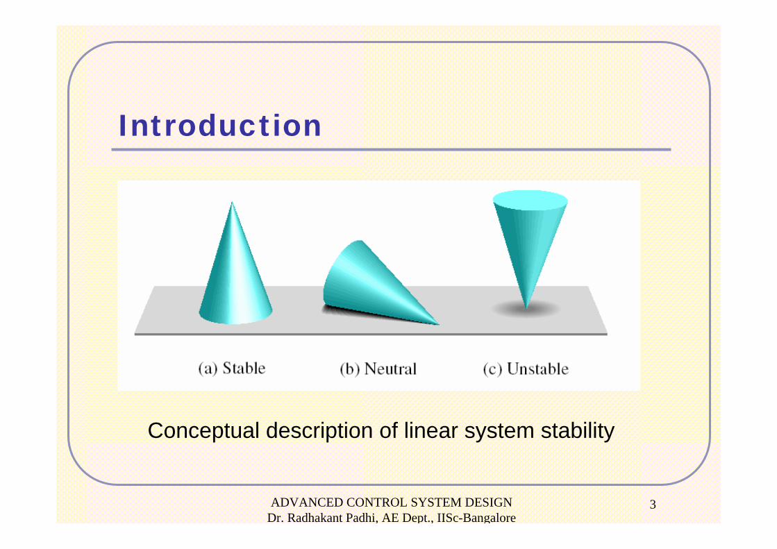
Introduction
Conceptual description of linear system stability
ADVANCED CONTROL SYSTEM DESIGN Dr. Radhakant Padhi, AE Dept., IISc-Bangalore
4
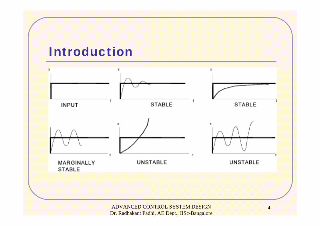
Introduction
ADVANCED CONTROL SYSTEM DESIGN Dr. Radhakant Padhi, AE Dept., IISc-Bangalore
5
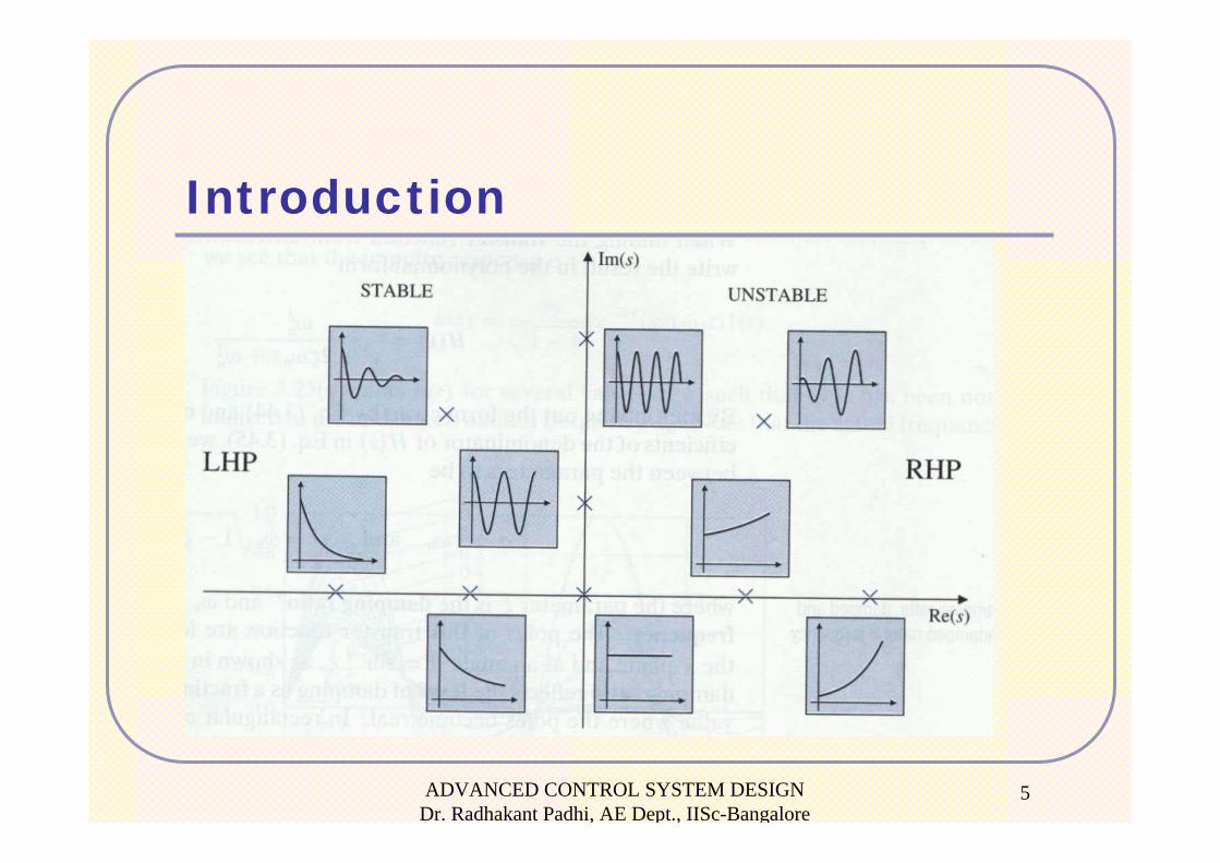
Introduction
ADVANCED CONTROL SYSTEM DESIGN Dr. Radhakant Padhi, AE Dept., IISc-Bangalore
6
Introduction
( ) ( )
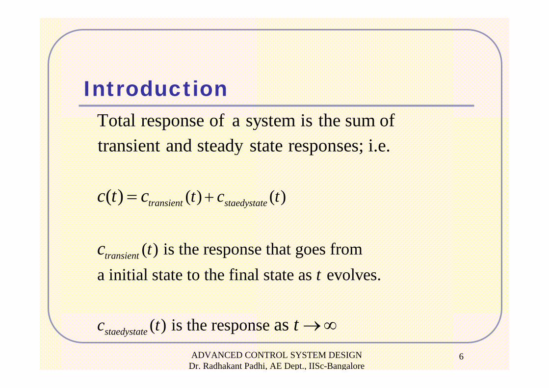
( ) is the response that goes from a initial state to the final state as evolves.
Total response of a system is the sum oftransient and steady state responses; i.e.
( ) transient staedystate
transient
t c t
tt
c t c
c
+=
( ) is the response as staedystatec t t →∞
ADVANCED CONTROL SYSTEM DESIGN Dr. Radhakant Padhi, AE Dept., IISc-Bangalore
7
Stability Definition
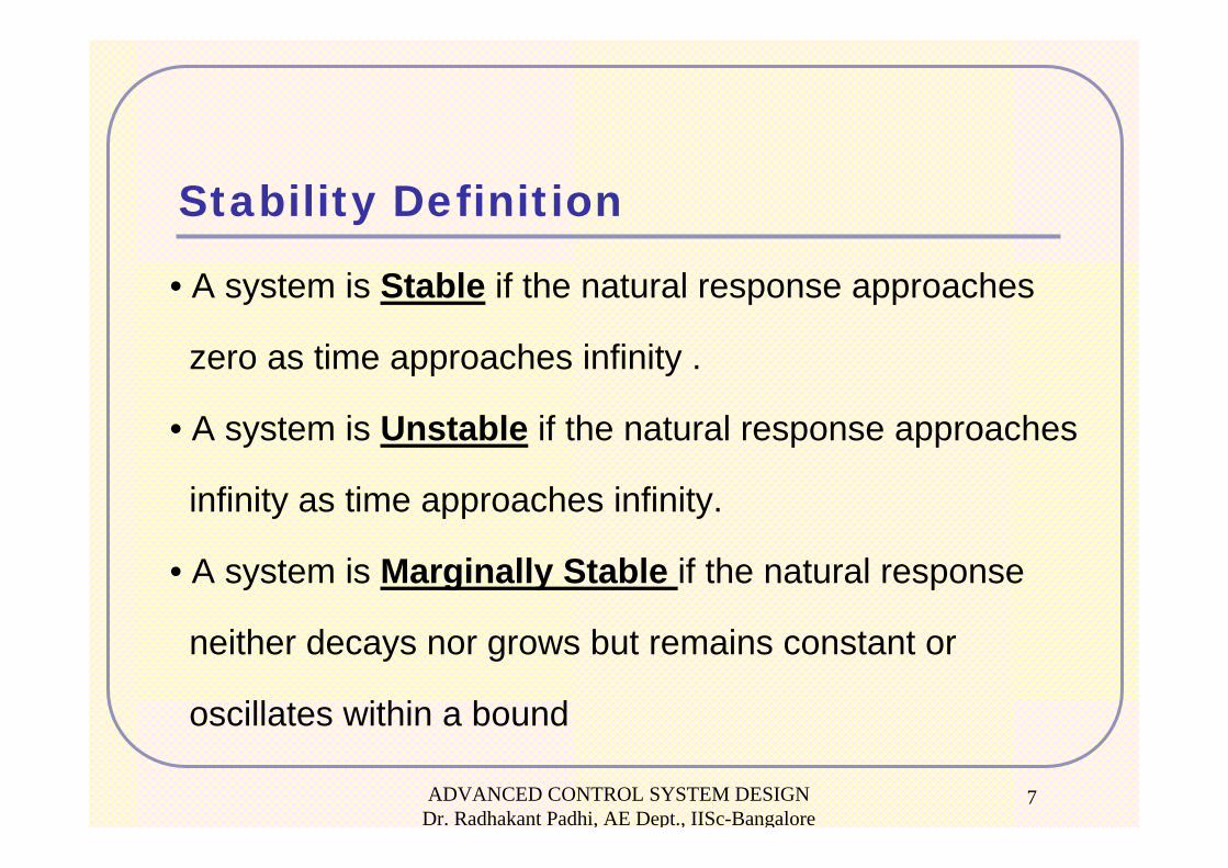
• A system is Stable if the natural response approaches
zero as time approaches infinity .
• A system is Unstable if the natural response approaches
infinity as time approaches infinity.
• A system is Marginally Stable if the natural response
neither decays nor grows but remains constant or
oscillates within a bound
ADVANCED CONTROL SYSTEM DESIGN Dr. Radhakant Padhi, AE Dept., IISc-Bangalore
8
Definition (BIBO Stability)
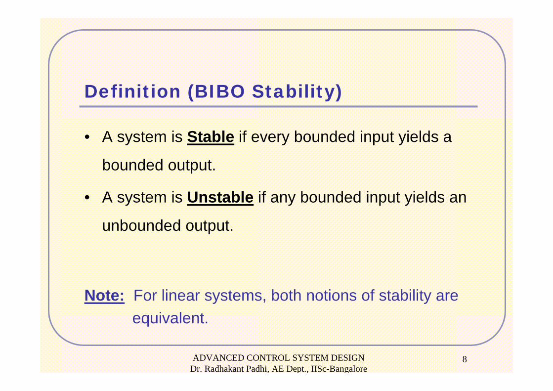
• A system is Stable if every bounded input yields a
bounded output.
• A system is Unstable if any bounded input yields an
unbounded output.
Note: For linear systems, both notions of stability are equivalent.
ADVANCED CONTROL SYSTEM DESIGN Dr. Radhakant Padhi, AE Dept., IISc-Bangalore
9
Stability Analysis from Closed Loop Transfer function
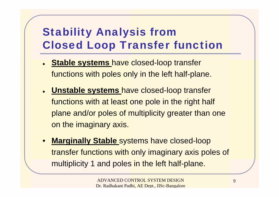
Stable systems have closed-loop transfer functions with poles only in the left half-plane.
Unstable systems have closed-loop transfer functions with at least one pole in the right half plane and/or poles of multiplicity greater than one on the imaginary axis.
• Marginally Stable systems have closed-loop transfer functions with only imaginary axis poles of multiplicity 1 and poles in the left half-plane.
ADVANCED CONTROL SYSTEM DESIGN Dr. Radhakant Padhi, AE Dept., IISc-Bangalore
10
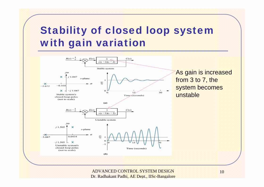
Stability of closed loop system with gain variation
As gain is increased from 3 to 7, the system becomes unstable
Routh–Hurwitz Approach for Stability Analysis
Dr. Radhakant PadhiAsst. Professor
Dept. of Aerospace EngineeringIndian Institute of Science - Bangalore
ADVANCED CONTROL SYSTEM DESIGN Dr. Radhakant Padhi, AE Dept., IISc-Bangalore
12
Sufficient Conditions for Instability and Marginal Stability:
• A system is Unstable if all signs of the coefficients of the denominator of the closed loop transfer function are not same.
• If powers of s are missing from the denominator of the closed loop transfer function, then the system is either Unstable or at best Marginally Stable
Question: What if all coefficients are positive and no power of s is missing?
Answer: Routh-Hurwitz criterion.
ADVANCED CONTROL SYSTEM DESIGN Dr. Radhakant Padhi, AE Dept., IISc-Bangalore
13
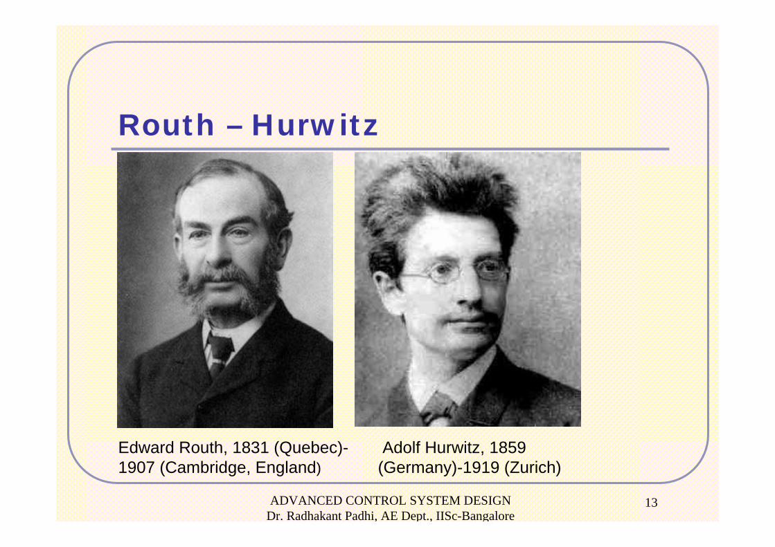
Routh – Hurwitz
Edward Routh, 1831 (Quebec)-1907 (Cambridge, England)
Adolf Hurwitz, 1859(Germany)-1919 (Zurich)
ADVANCED CONTROL SYSTEM DESIGN Dr. Radhakant Padhi, AE Dept., IISc-Bangalore
14
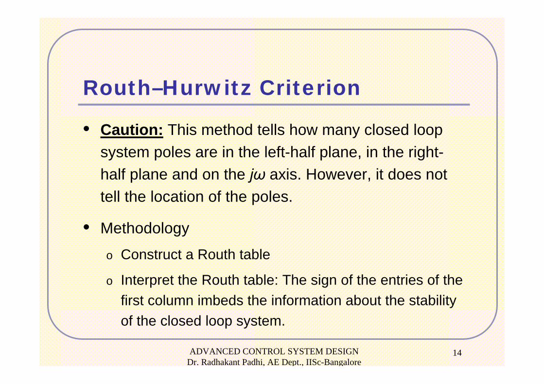
Routh–Hurwitz Criterion
• Caution: This method tells how many closed loop system poles are in the left-half plane, in the right-half plane and on the jω axis. However, it does not tell the location of the poles.
• Methodology
o Construct a Routh table
o Interpret the Routh table: The sign of the entries of the first column imbeds the information about the stability of the closed loop system.
ADVANCED CONTROL SYSTEM DESIGN Dr. Radhakant Padhi, AE Dept., IISc-Bangalore
15
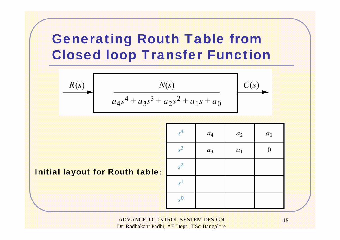
Generating Routh Table from Closed loop Transfer Function
Initial layout for Routh table:
ADVANCED CONTROL SYSTEM DESIGN Dr. Radhakant Padhi, AE Dept., IISc-Bangalore
16
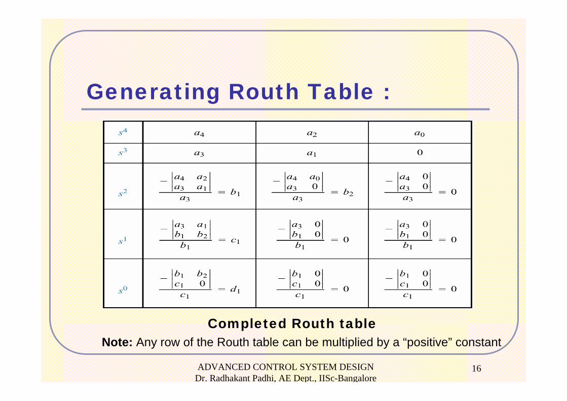
Generating Routh Table :
Completed Routh tableNote: Any row of the Routh table can be multiplied by a “positive” constant
ADVANCED CONTROL SYSTEM DESIGN Dr. Radhakant Padhi, AE Dept., IISc-Bangalore
17
Interpreting the Routh Table
• The no. of roots of the polynomial that are in
the right half-plane is equal to the number of
sign changes in the first column.
• A system is Stable if there are no sign
changes in the first column of the Routh
table.
ADVANCED CONTROL SYSTEM DESIGN Dr. Radhakant Padhi, AE Dept., IISc-Bangalore
18
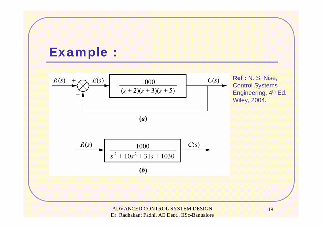
Example :
Ref : N. S. Nise,Control Systems Engineering, 4th Ed. Wiley, 2004.
ADVANCED CONTROL SYSTEM DESIGN Dr. Radhakant Padhi, AE Dept., IISc-Bangalore
19
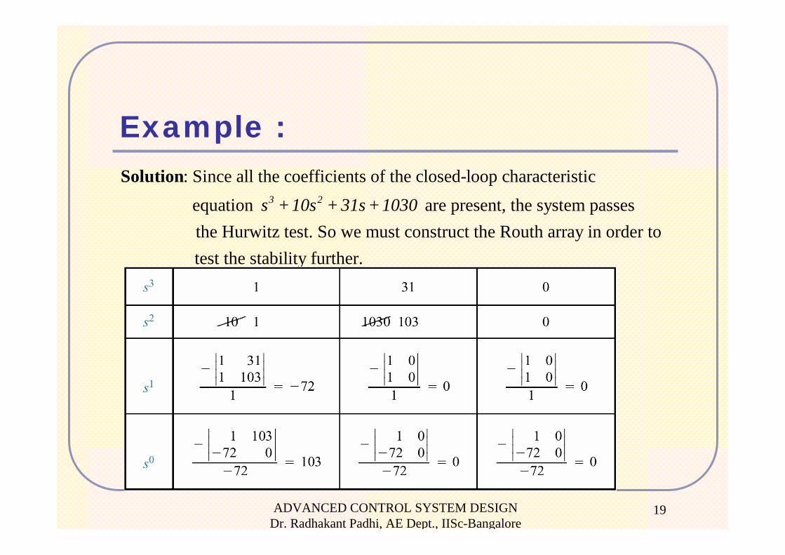
Example :: Since all the coefficients of the closed-loop characteristic equation are present, the system passes the Hurwitz test. So we must construct the Routh array in order to
3 2s + 10s + 31s + 1030Solution
test the stability further.
ADVANCED CONTROL SYSTEM DESIGN Dr. Radhakant Padhi, AE Dept., IISc-Bangalore
20
Example :
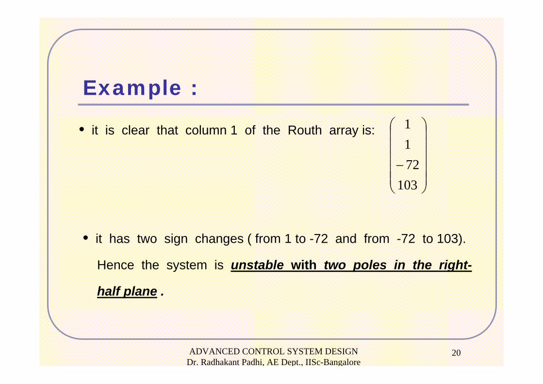
• it is clear that column 1 of the Routh array is:
⎟⎟⎟⎟⎟
⎠
⎞
⎜⎜⎜⎜⎜
⎝
⎛
−103
7211
• it has two sign changes ( from 1 to -72 and from -72 to 103).
Hence the system is unstable with two poles in the right-
half plane .
ADVANCED CONTROL SYSTEM DESIGN Dr. Radhakant Padhi, AE Dept., IISc-Bangalore
21
Routh-Hurwitz Criterion:Special Cases
The basic Routh table check fails in the following two cases:
• Zero only in the first column of a row
• Entire row consisting of zeros
These cases need further analysis
ADVANCED CONTROL SYSTEM DESIGN Dr. Radhakant Padhi, AE Dept., IISc-Bangalore
22
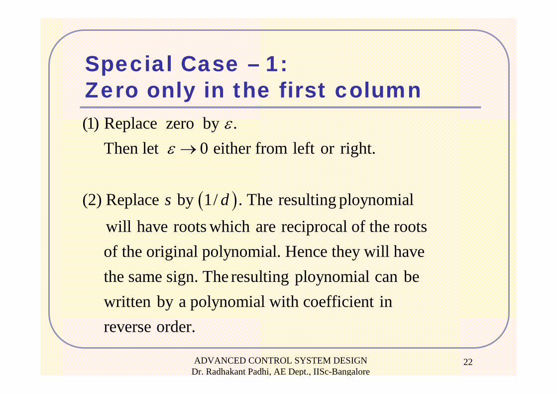
Special Case – 1:Zero only in the first column
( )
(1) Replace zero by . Then let 0 either from left or right.
(2) Replace by 1/ . The resulting ploynomial will have roots which are reciprocal of the roots of the original polynomial. Hence they will hav
s d
εε →
e the same sign. The resulting ploynomial can be written by a polynomial with coefficient in reverse order.
ADVANCED CONTROL SYSTEM DESIGN Dr. Radhakant Padhi, AE Dept., IISc-Bangalore
23
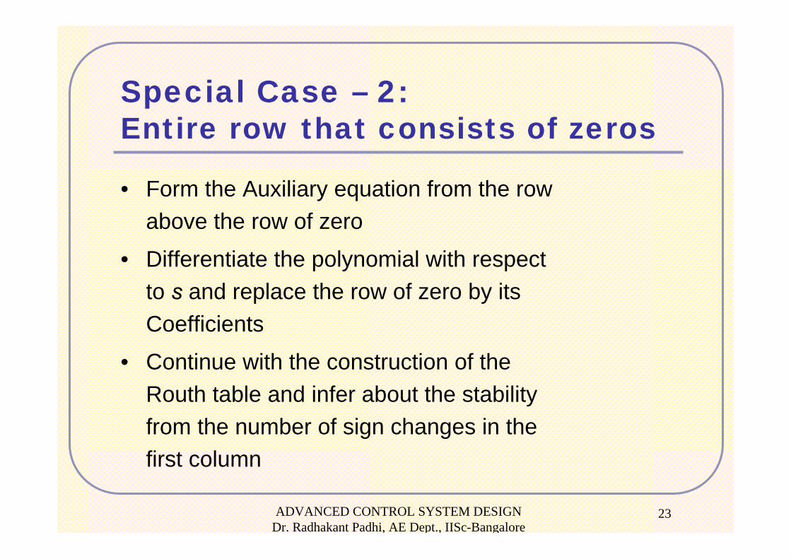
Special Case – 2:Entire row that consists of zeros
• Form the Auxiliary equation from the row above the row of zero
• Differentiate the polynomial with respect to s and replace the row of zero by its Coefficients
• Continue with the construction of the Routh table and infer about the stability from the number of sign changes in the first column
ADVANCED CONTROL SYSTEM DESIGN Dr. Radhakant Padhi, AE Dept., IISc-Bangalore
24
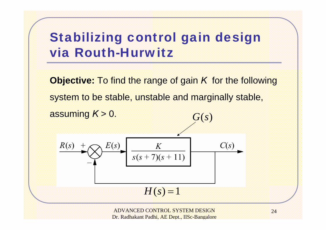
Stabilizing control gain design via Routh-Hurwitz
Objective: To find the range of gain K for the following
system to be stable, unstable and marginally stable,
assuming K > 0. ( )G s
( ) 1H s =
ADVANCED CONTROL SYSTEM DESIGN Dr. Radhakant Padhi, AE Dept., IISc-Bangalore
25
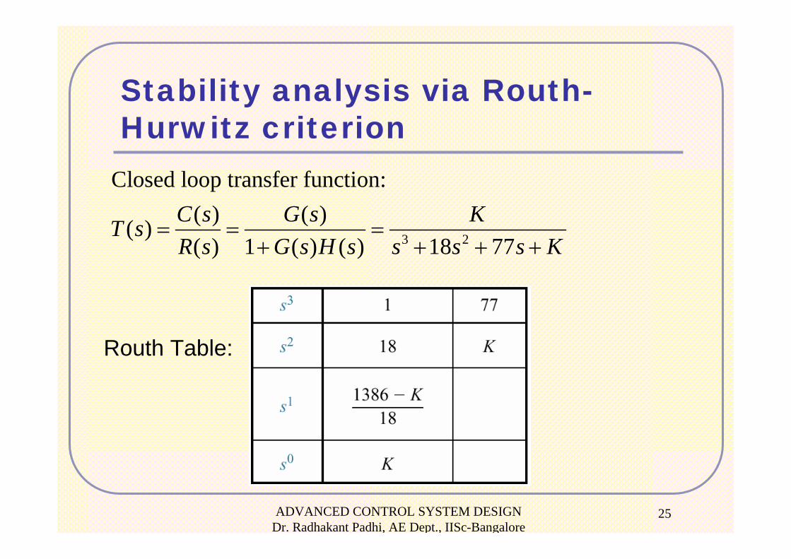
Stability analysis via Routh-Hurwitz criterion
3 2
Closed loop transfer function: ( ) ( )( )( ) 1 ( ) ( ) 18 77
C s G s KT sR s G s H s s s s K
= = =+ + + +
Routh Table:
ADVANCED CONTROL SYSTEM DESIGN Dr. Radhakant Padhi, AE Dept., IISc-Bangalore
26
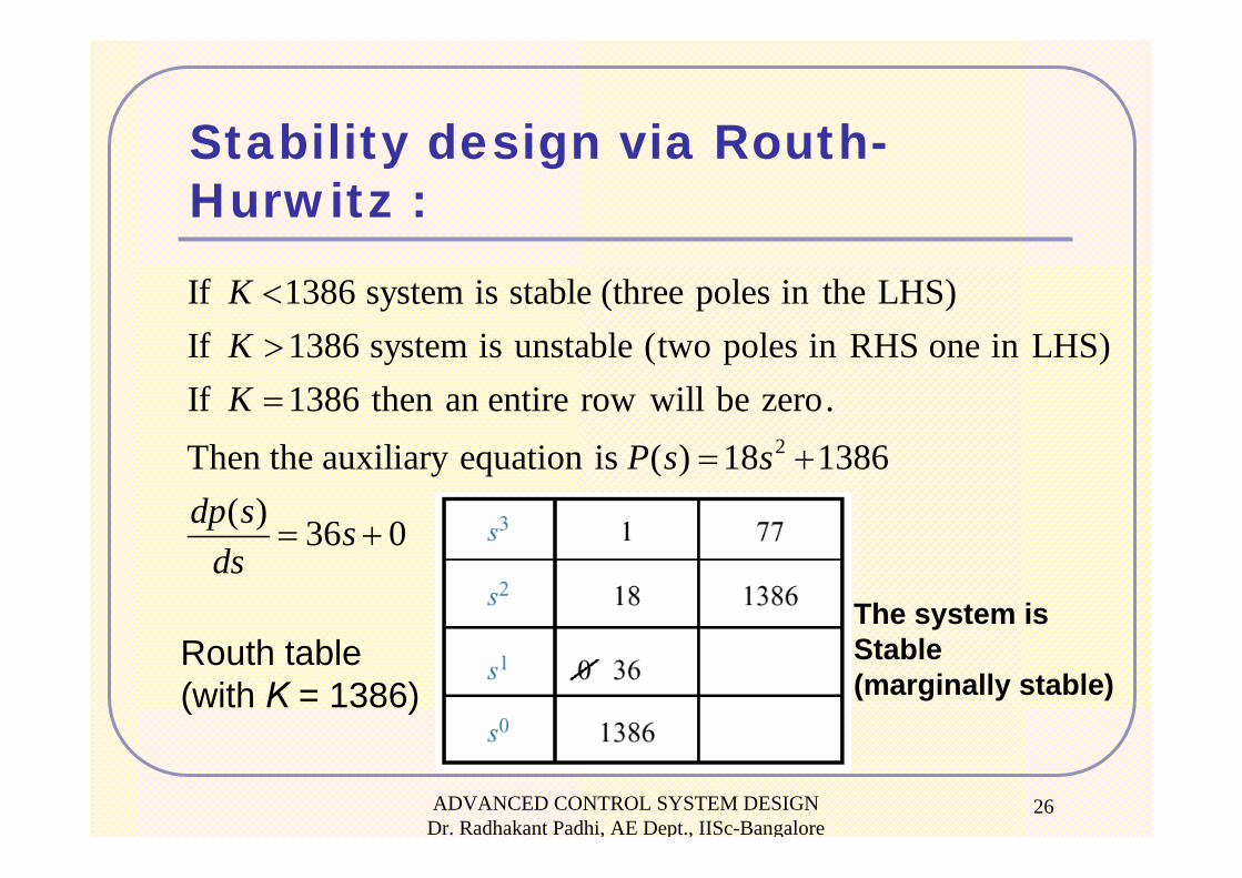
Stability design via Routh-Hurwitz :
2
If 1386 system is stable (three poles in the LHS)If 1386 system is unstable (two poles in RHS one in LHS)If 1386 then an entire row will be zero. Then the auxiliary equation is ( ) 18 1386
( ) 36 0
KKK
P s sdp s s
ds
<>=
= +
= +
Routh table (with K = 1386)
The system is Stable (marginally stable)
Steady State Error Analysis
Dr. Radhakant PadhiAsst. Professor
Dept. of Aerospace EngineeringIndian Institute of Science - Bangalore
ADVANCED CONTROL SYSTEM DESIGN Dr. Radhakant Padhi, AE Dept., IISc-Bangalore
28
Definition and Test Inputs
Steady-state error is the difference between the input and the output for a prescribed test input as
Usual test inputs used for steady-state error analysis and design are Step, Ramp and Parabola inputs (justification comes from the Taylor series analysis).
t → ∞
ADVANCED CONTROL SYSTEM DESIGN Dr. Radhakant Padhi, AE Dept., IISc-Bangalore
29
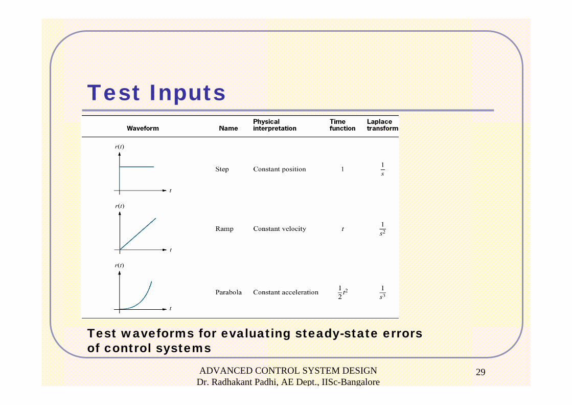
Test Inputs
Test waveforms for evaluating steady-state errors of control systems
ADVANCED CONTROL SYSTEM DESIGN Dr. Radhakant Padhi, AE Dept., IISc-Bangalore
30
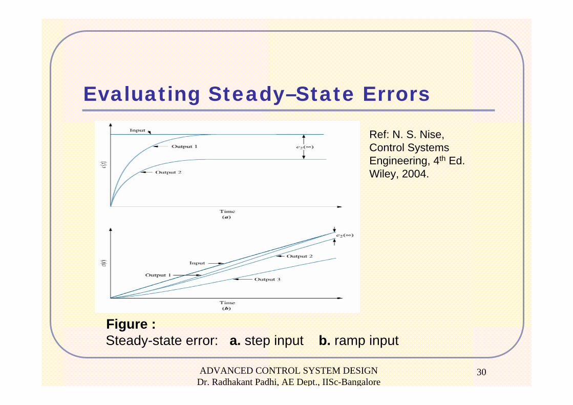
Evaluating Steady–State Errors
Figure : Steady-state error: a. step input b. ramp input
Ref: N. S. Nise,Control Systems Engineering, 4th Ed. Wiley, 2004.
ADVANCED CONTROL SYSTEM DESIGN Dr. Radhakant Padhi, AE Dept., IISc-Bangalore
31
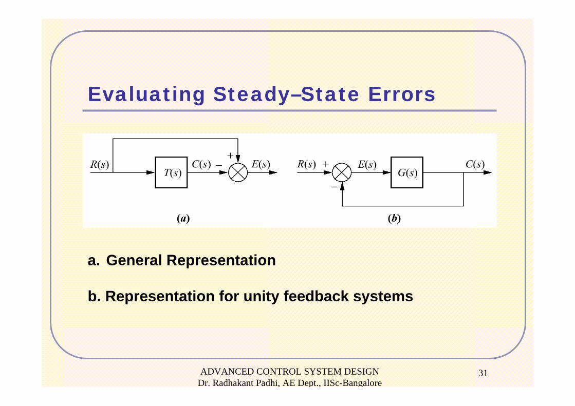
Evaluating Steady–State Errors
a. General Representation
b. Representation for unity feedback systems
ADVANCED CONTROL SYSTEM DESIGN Dr. Radhakant Padhi, AE Dept., IISc-Bangalore
32
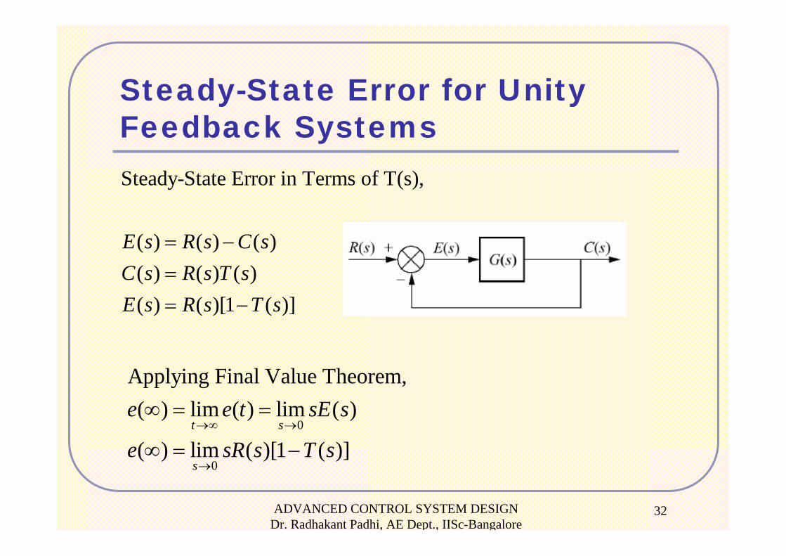
Steady-State Error for Unity Feedback SystemsSteady-State Error in Terms of T(s),
( ) ( ) ( )( ) ( ) ( )( ) ( )[1 ( )]
E s R s C sC s R s T sE s R s T s
= −== −
0
0
Applying Final Value Theorem,( ) lim ( ) lim ( )
( ) lim ( )[1 ( )]t s
s
e e t sE s
e sR s T s→∞ →
→
∞ = =
∞ = −
ADVANCED CONTROL SYSTEM DESIGN Dr. Radhakant Padhi, AE Dept., IISc-Bangalore
33
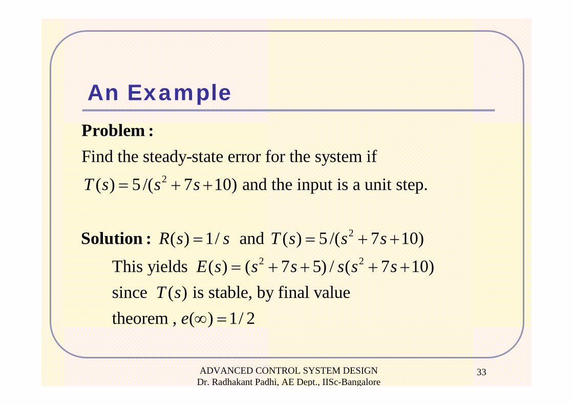
An Example
2
2
2 2
Find the steady-state error for the system if( ) 5 /( 7 10) and the input is a unit step.
( ) 1/ and ( ) 5 /( 7 10) This yields ( ) ( 7 5) / ( 7 10) since
T s s s
R s s T s s sE s s s s s s
= + +
= = + +
= + + + +
Problem :
Solution :
( ) is stable, by final value theorem , ( ) 1/ 2
T se ∞ =
ADVANCED CONTROL SYSTEM DESIGN Dr. Radhakant Padhi, AE Dept., IISc-Bangalore
34
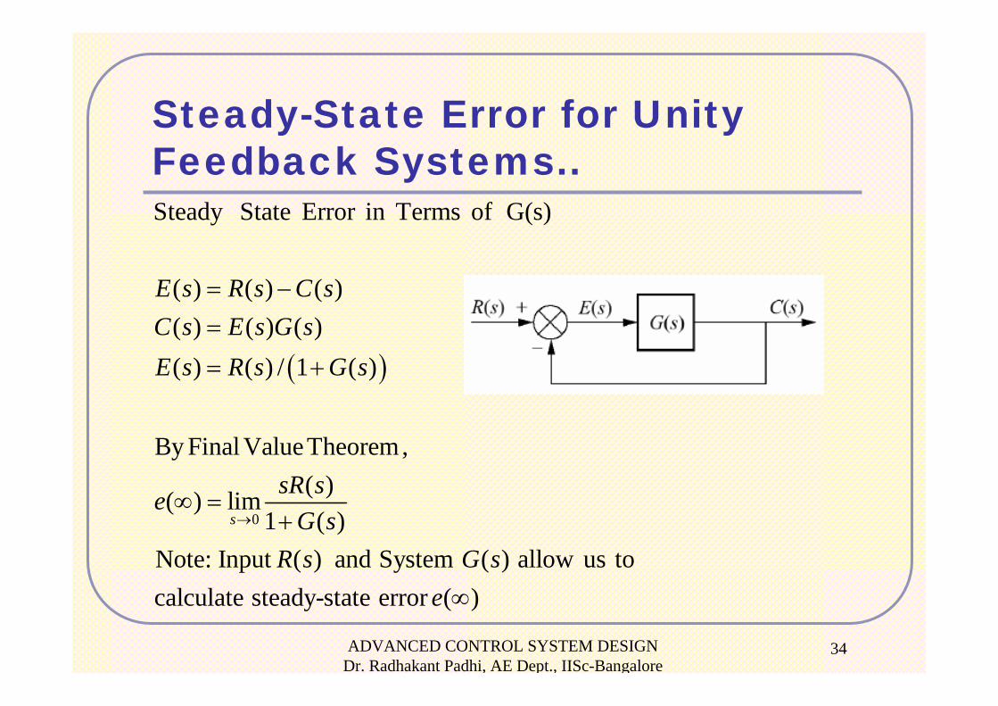
Steady-State Error for Unity Feedback Systems..
( )
0
Steady State Error in Terms of G(s)
( ) ( ) ( )( ) ( ) ( )( ) ( ) / 1 ( )
By Final ValueTheorem,( )( ) lim
1 ( )Note: Input ( ) and System ( ) allow us tocalculate steady-state error ( )
s
E s R s C sC s E s G sE s R s G s
sR seG s
R s G se
→
= −=
= +
∞ =+
∞
ADVANCED CONTROL SYSTEM DESIGN Dr. Radhakant Padhi, AE Dept., IISc-Bangalore
35
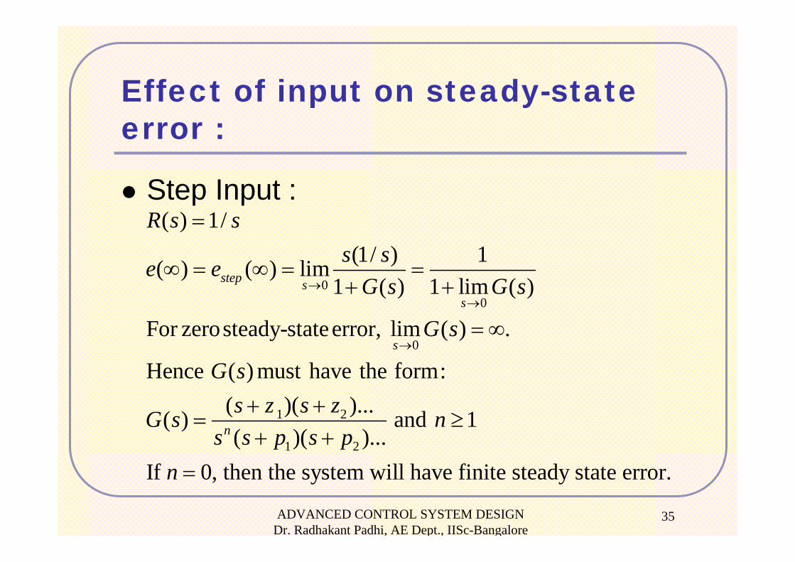
Effect of input on steady-state error :
Step Input :
00
0
1 2
1 2
( ) 1/(1/ ) 1( ) ( ) lim
1 ( ) 1 lim ( )
For zerosteady-stateerror, lim ( ) .
Hence ( ) must have the form:( )( )...( ) and 1( )( )...
If 0, then the system will have fini
step ss
s
n
R s ss se e
G s G s
G s
G ss z s zG s n
s s p s pn
→→
→
=
∞ = ∞ = =+ +
= ∞
+ += ≥
+ += te steady state error.
ADVANCED CONTROL SYSTEM DESIGN Dr. Radhakant Padhi, AE Dept., IISc-Bangalore
36
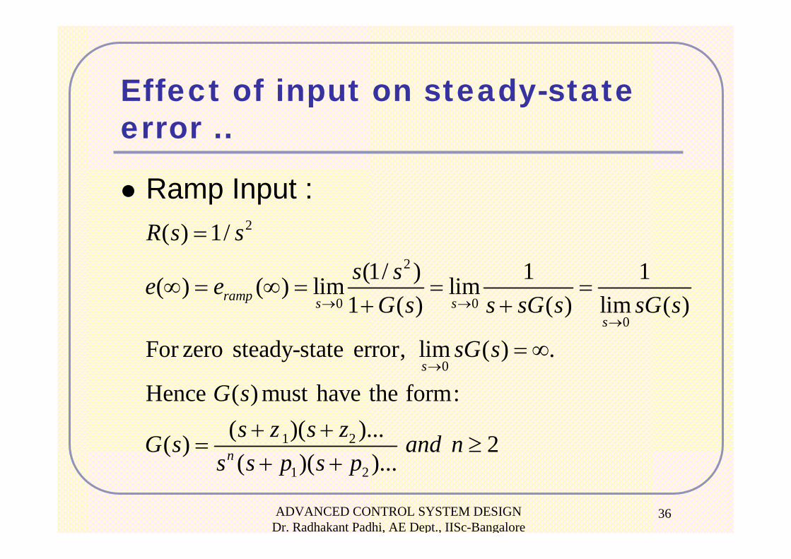
Effect of input on steady-state error ..
Ramp Input :2
2
0 00
0
1 2
1 2
( ) 1/(1/ ) 1 1( ) ( ) lim lim
1 ( ) ( ) lim ( )
For zero steady-state error, lim ( ) .
Hence ( ) must have the form:( )( )...( ) 2( )( )...
ramp s ss
s
n
R s ss se e
G s s sG s sG s
sG s
G ss z s zG s and n
s s p s p
→ →→
→
=
∞ = ∞ = = =+ +
= ∞
+ += ≥
+ +
ADVANCED CONTROL SYSTEM DESIGN Dr. Radhakant Padhi, AE Dept., IISc-Bangalore
37
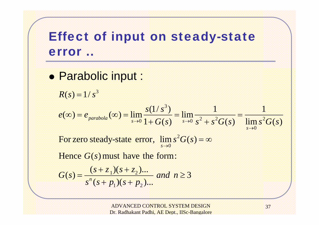
Effect of input on steady-state error ..
Parabolic input :3
3
2 2 20 00
2
0
1 2
1 2
( ) 1/(1/ ) 1 1( ) ( ) lim lim
1 ( ) ( ) lim ( )
For zero steady-state error, lim ( )
Hence ( ) must have the form:( )( )...( ) 3( )( )...
parabola s ss
s
n
R s ss se e
G s s s G s s G s
s G s
G ss z s zG s and n
s s p s p
→ →→
→
=
∞ = ∞ = = =+ +
= ∞
+ += ≥
+ +
ADVANCED CONTROL SYSTEM DESIGN Dr. Radhakant Padhi, AE Dept., IISc-Bangalore
38
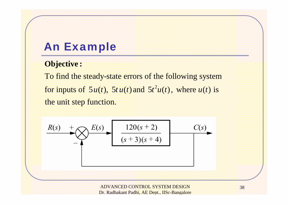
An Example
2
To find the steady-state errors of the following systemfor inputs of 5 ( ), 5 ( ) and 5 ( ) , where ( ) is the unit step function.
u t t u t t u t u t
Objective :
ADVANCED CONTROL SYSTEM DESIGN Dr. Radhakant Padhi, AE Dept., IISc-Bangalore
39
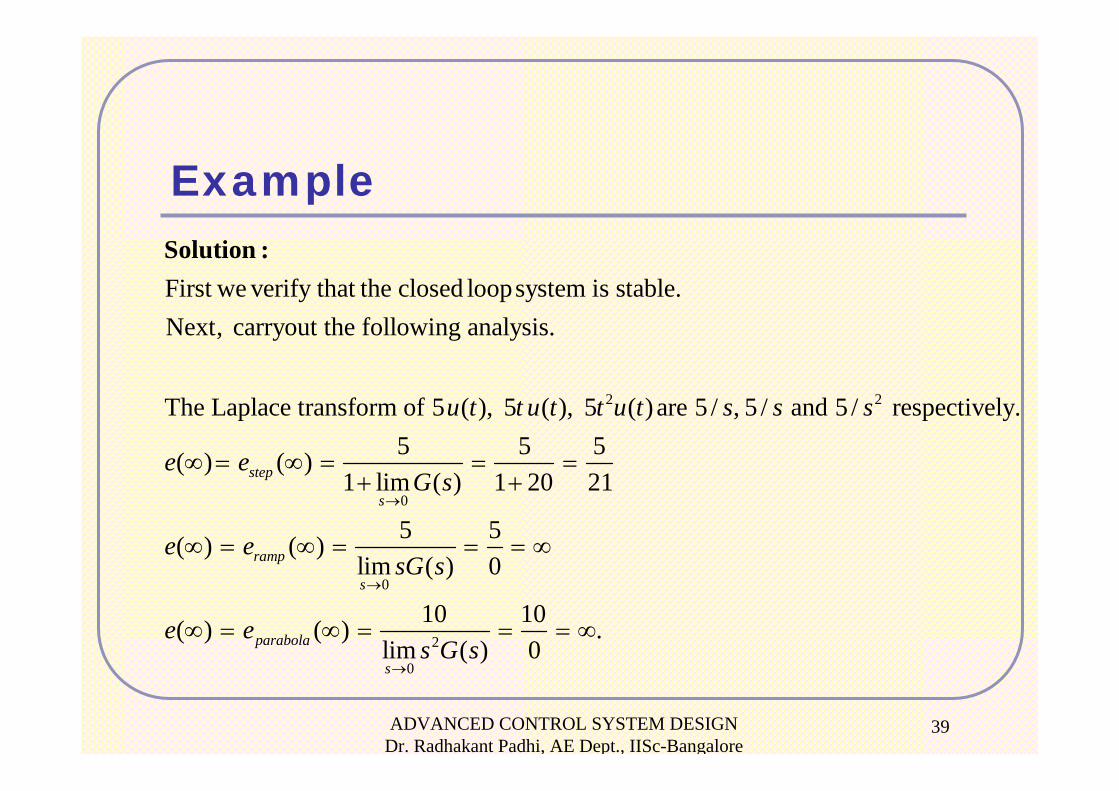
Example
2 2
0
First we verify that the closed loopsystem is stable.Next, carryout the following analysis.
The Laplace transform of 5 ( ), 5 ( ), 5 ( ) are 5 / , 5 / and 5 / respectively.5( ) ( )
1 limstep
s
u t t u t t u t s s s
e e→
∞ = ∞ =+
Solution :
0
2
0
5 5( ) 1 20 21
5 5( ) ( )lim ( ) 0
10 10( ) ( ) .lim ( ) 0
ramp
s
parabola
s
G s
e esG s
e es G s
→
→
= =+
∞ = ∞ = = = ∞
∞ = ∞ = = = ∞
ADVANCED CONTROL SYSTEM DESIGN Dr. Radhakant Padhi, AE Dept., IISc-Bangalore
40
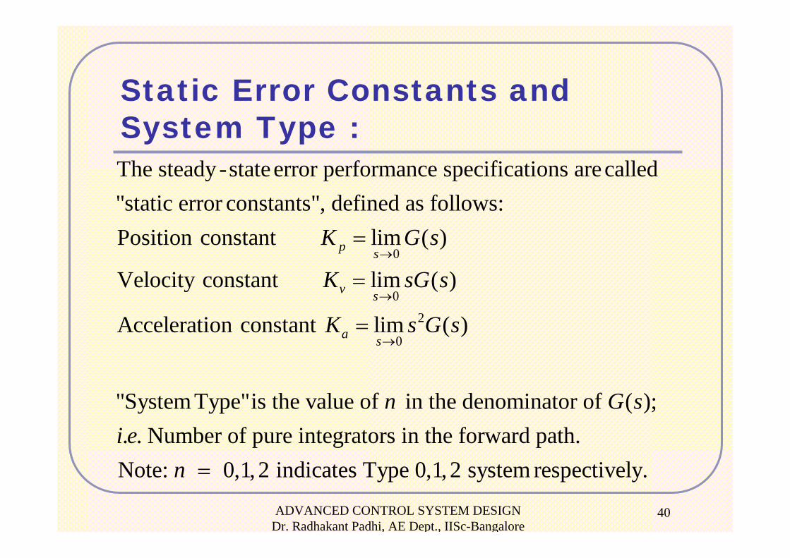
Static Error Constants and System Type :
0
0
The steady -stateerror performance specifications arecalled"static error constants", defined as follows:Position constant lim ( )
Velocity constant lim ( )
Acceleration constant li
p s
v s
a
K G s
K sG s
K
→
→
=
=
= 2
0m ( )
"System Type"is the value of in the denominator of ( );. . Number of pure integrators in the forward path.Note: 0,1, 2 indicates Type 0,1,2 system respectively.
ss G s
n G si e
n
→
=
ADVANCED CONTROL SYSTEM DESIGN Dr. Radhakant Padhi, AE Dept., IISc-Bangalore
41
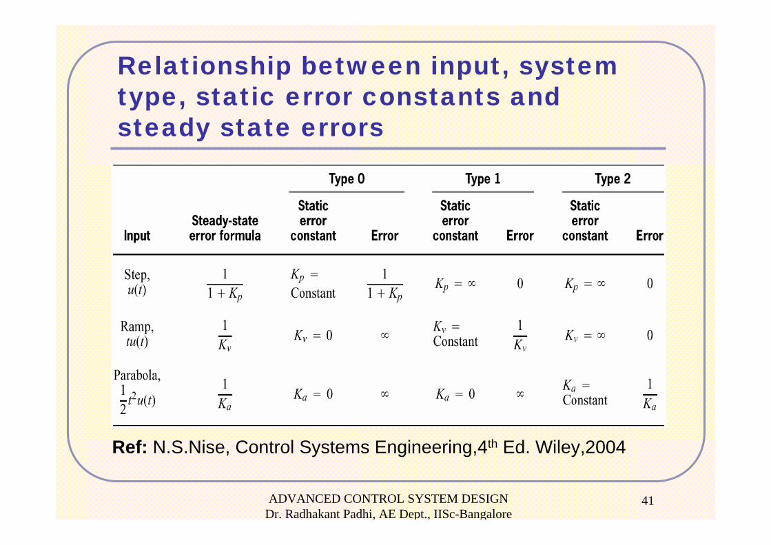
Relationship between input, system type, static error constants and steady state errors
Ref: N.S.Nise, Control Systems Engineering,4th Ed. Wiley,2004
ADVANCED CONTROL SYSTEM DESIGN Dr. Radhakant Padhi, AE Dept., IISc-Bangalore
42
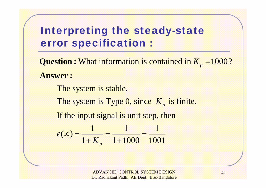
Interpreting the steady-state error specification :
What information is contained in 1000?
The system is stable. The system is Type 0, since is finite.
If the input signal is unit step, then
(
p
p
K
K
e
=Question :
Answer :
1 1 1)1 1 1000 1001pK
∞ = = =+ +
ADVANCED CONTROL SYSTEM DESIGN Dr. Radhakant Padhi, AE Dept., IISc-Bangalore
43
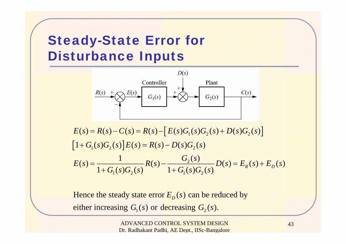
Steady-State Error for Disturbance Inputs
[ ][ ]
1 2 2
1 2 2
2
1 2 1 2
( ) ( ) ( ) ( ) ( ) ( ) ( ) ( ) ( )
1 ( ) ( ) ( ) ( ) ( ) ( )( )1( ) ( ) ( ) ( ) ( )
1 ( ) ( ) 1 ( ) ( )
Hence the steady state error ( ) can be reduced by either increasin
R D
D
E s R s C s R s E s G s G s D s G s
G s G s E s R s D s G sG sE s R s D s E s E s
G s G s G s G s
E s
= − = − +
+ = −
= − = ++ +
1 2g ( ) or decreasing ( ).G s G s
ADVANCED CONTROL SYSTEM DESIGN Dr. Radhakant Padhi, AE Dept., IISc-Bangalore
44
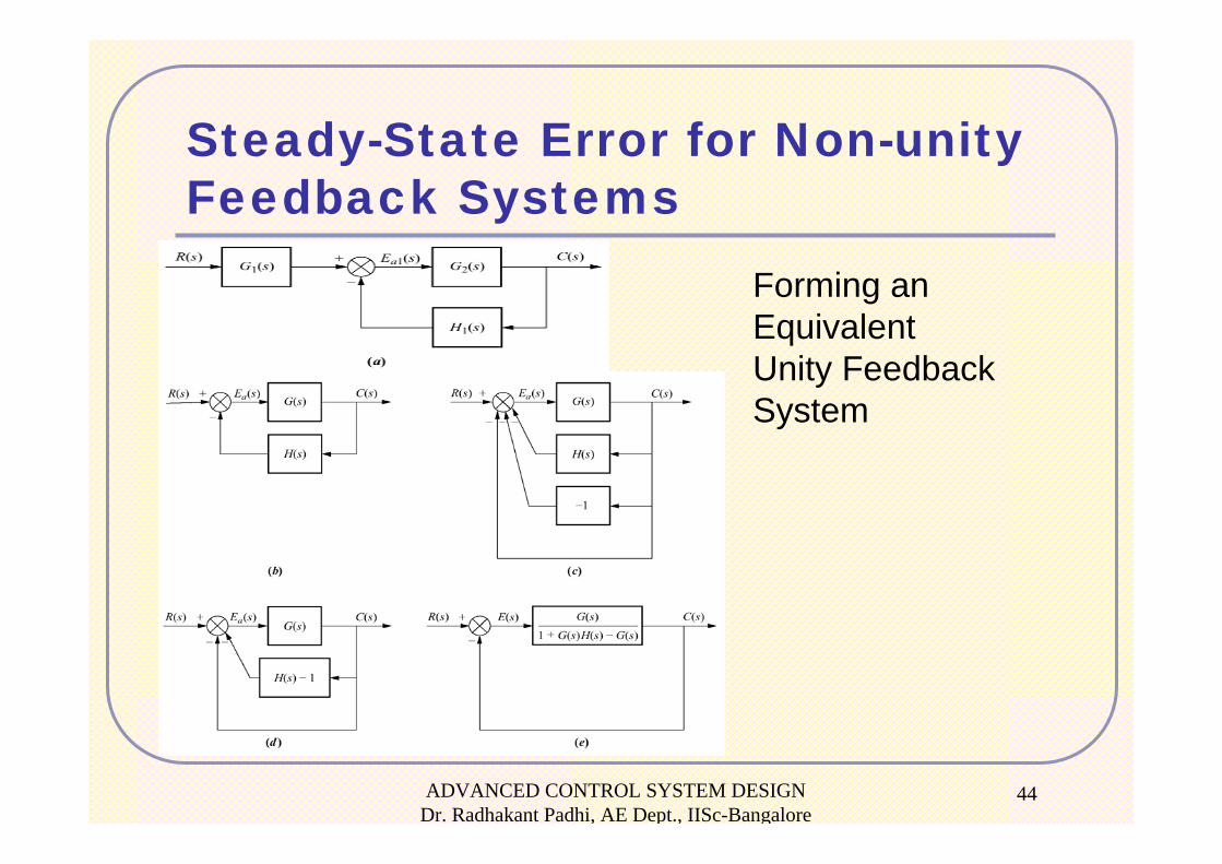
Steady-State Error for Non-unityFeedback Systems
Forming anEquivalent Unity FeedbackSystem
ADVANCED CONTROL SYSTEM DESIGN Dr. Radhakant Padhi, AE Dept., IISc-Bangalore
45
Sensitivity
The degree to which changes in system parameters
affect system transfer functions, and hence
performance, is called sensitivity.
The greater the sensitivity, the less desirable the
effect of a parameter change.
ADVANCED CONTROL SYSTEM DESIGN Dr. Radhakant Padhi, AE Dept., IISc-Bangalore
46
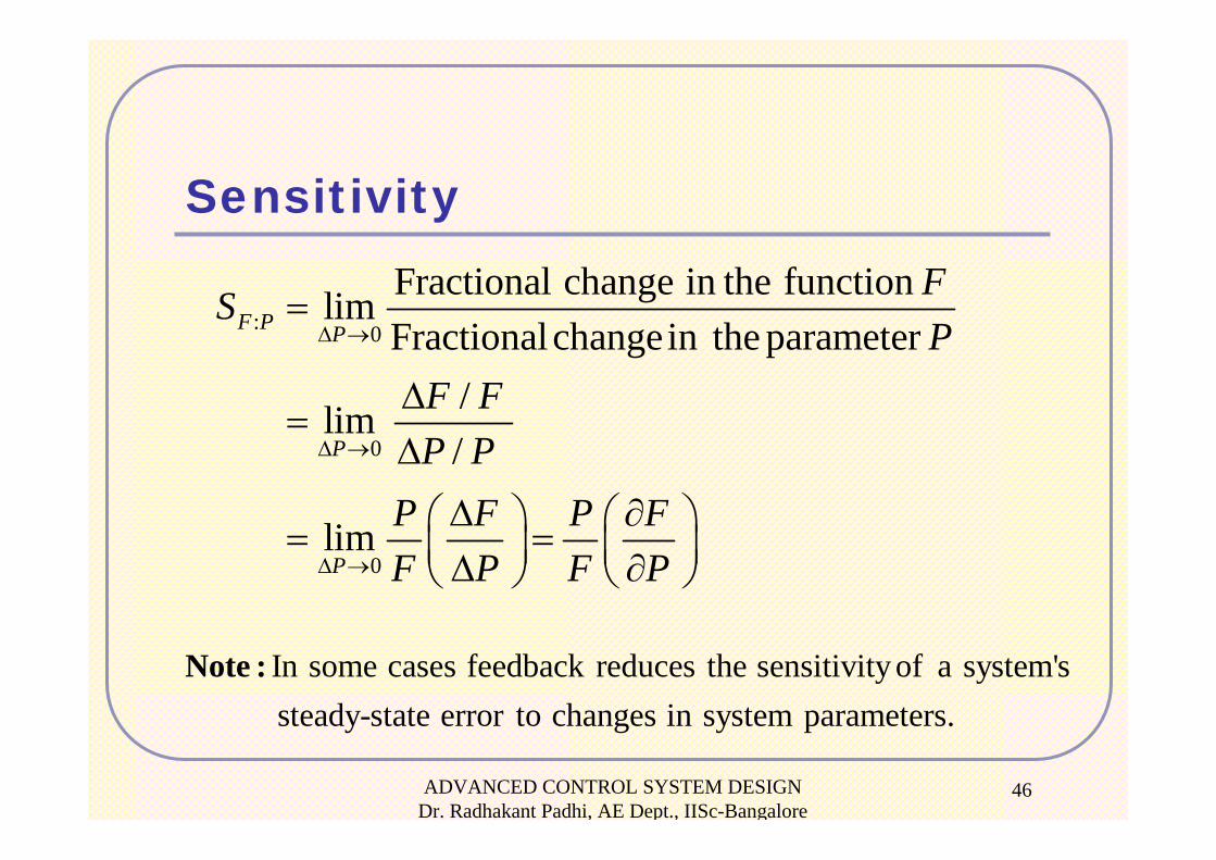
Sensitivity
: 0
0
0
Fractional change in the functionlimFractionalchangein the parameter
/lim/
lim
F P P
P
P
FSP
F FP P
P F P FF P F P
Δ →
Δ →
Δ →
=
Δ=
Δ
Δ ∂⎛ ⎞ ⎛ ⎞= =⎜ ⎟ ⎜ ⎟Δ ∂⎝ ⎠ ⎝ ⎠
In some cases feedback reduces the sensitivity of a system's steady-state error to changes in system parameters.
Note :
ADVANCED CONTROL SYSTEM DESIGN Dr. Radhakant Padhi, AE Dept., IISc-Bangalore
47
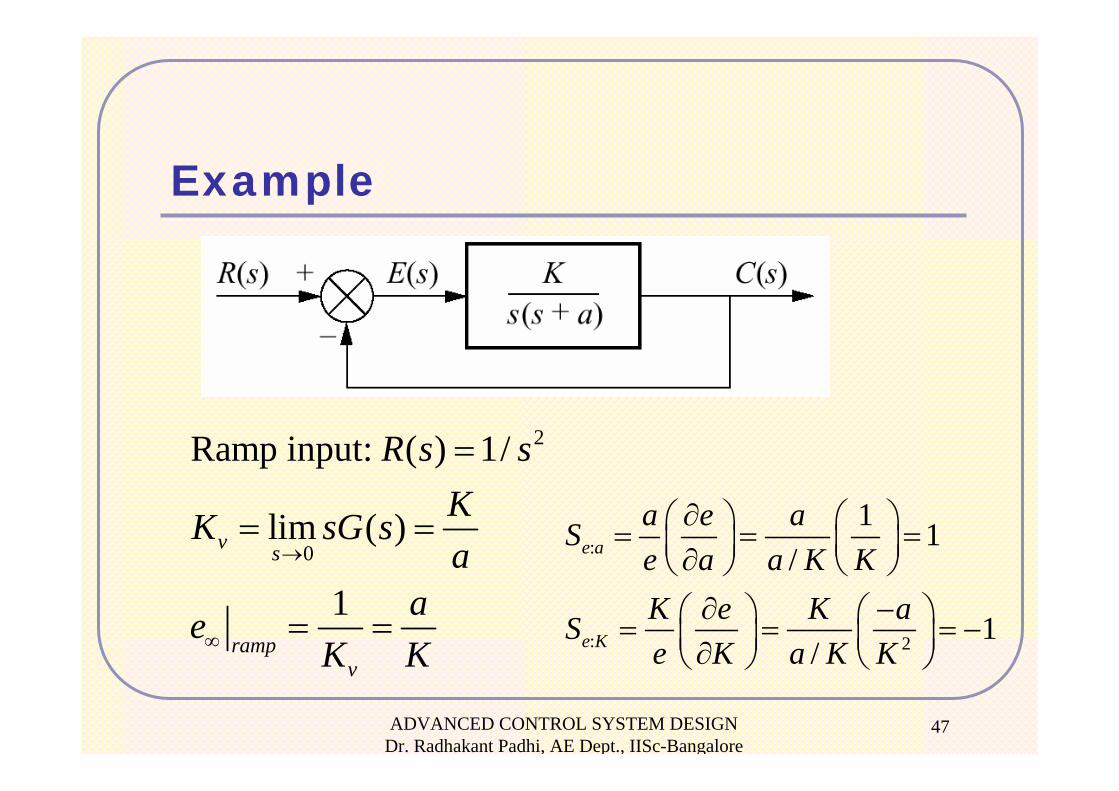
Example
2
0
Ramp input: ( ) 1/
lim ( )
1
v s
rampv
R s sKK sG sa
aeK K
→
∞
=
= =
= =
:
: 2
1 1/
1/
e a
e K
a e aSe a a K KK e K aSe K a K K
∂⎛ ⎞ ⎛ ⎞= = =⎜ ⎟ ⎜ ⎟∂⎝ ⎠ ⎝ ⎠∂ −⎛ ⎞ ⎛ ⎞= = = −⎜ ⎟ ⎜ ⎟∂⎝ ⎠ ⎝ ⎠
ADVANCED CONTROL SYSTEM DESIGN Dr. Radhakant Padhi, AE Dept., IISc-Bangalore
48
ADVANCED CONTROL SYSTEM DESIGN Dr. Radhakant Padhi, AE Dept., IISc-Bangalore
49