Embed Size (px)
Citation preview
Lecture 15: Specific Flow Phenomena Extracts from : “The Essential CANDU, A Textbook on the CANDU Nuclear Power
Plant Technology”, Editor-in-Chief Wm. J. Garland, Chapters 6 & 7, University Network of Excellence in Nuclear Engineering (UNENE), ISBN 0-9730040. Textbook retrieved from: www.nuceng.ca/candu.
Vinh Q. Tang, Ph.D., P.Eng
Adjunct Professor
MAAE 4906F Reactor Thermal Hydraulic Fundamentals
1
Carleton UniversityDepartment of Mechanical and Aerospace Engineering
[email protected]: ME2186
Winter 2018
Course Contents
• Part 1: Thermal Hydraulic Design (Chapter 6 of textbook)
• Part 2: Thermal Hydraulic Analysis
• Part 3: Safety Regulations
2Winter 2018
Part 1: Thermal Hydraulic Design (Chapter 6 of textbook)
Contents• Reactor Overview (Lecture 1)
• Thermal Hydraulic Design Requirements (Lecture 2)
• Thermal Hydraulic Design Limits and Margins (Lecture 3)
• Thermal Hydraulic Design Fundamentals (Lectures 4-6)
• Heat Transfer and Fluid Flow Design (Lectures 7 to 15)
3Winter 2018
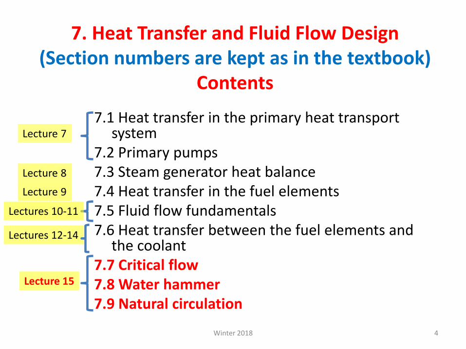
7. Heat Transfer and Fluid Flow Design(Section numbers are kept as in the textbook)
Contents
7.1 Heat transfer in the primary heat transport system
7.2 Primary pumps 7.3 Steam generator heat balance7.4 Heat transfer in the fuel elements7.5 Fluid flow fundamentals7.6 Heat transfer between the fuel elements and
the coolant7.7 Critical flow7.8 Water hammer7.9 Natural circulation
4
Lecture 7
Lecture 8
Lecture 9
Lectures 10-11
Lectures 12-14
Lecture 15
Winter 2018
Lecture 157.7 Critical flow
7.8 Water hammer
7.9 Natural circulation
5Winter 2018
7.7 Critical flow
Consider a situation in which fluid discharges from a container at high pressure to a container at lower pressure (or lower “back-pressure”)
The flow would increase as the back-pressure is reduced
Winter 2018 6
Winter 2018 7
When the back-pressure is sufficiently reduced …
… to cause the flow velocity to be equal to the speed of sound,…
… the mass flow at the exit would attain a maximum value
Winter 2018 8
i.e., The flow velocity has reached the speed of sound (note that mass flow rate can be
changed if the magnitude of the high pressure (or density) is changed)
The flow remains at the maximum value, which is referred to as “critical” or
“chocked” flow.
Further reduction in the back-pressure results in no further increase in mass flow
rate.
Winter 2018 9
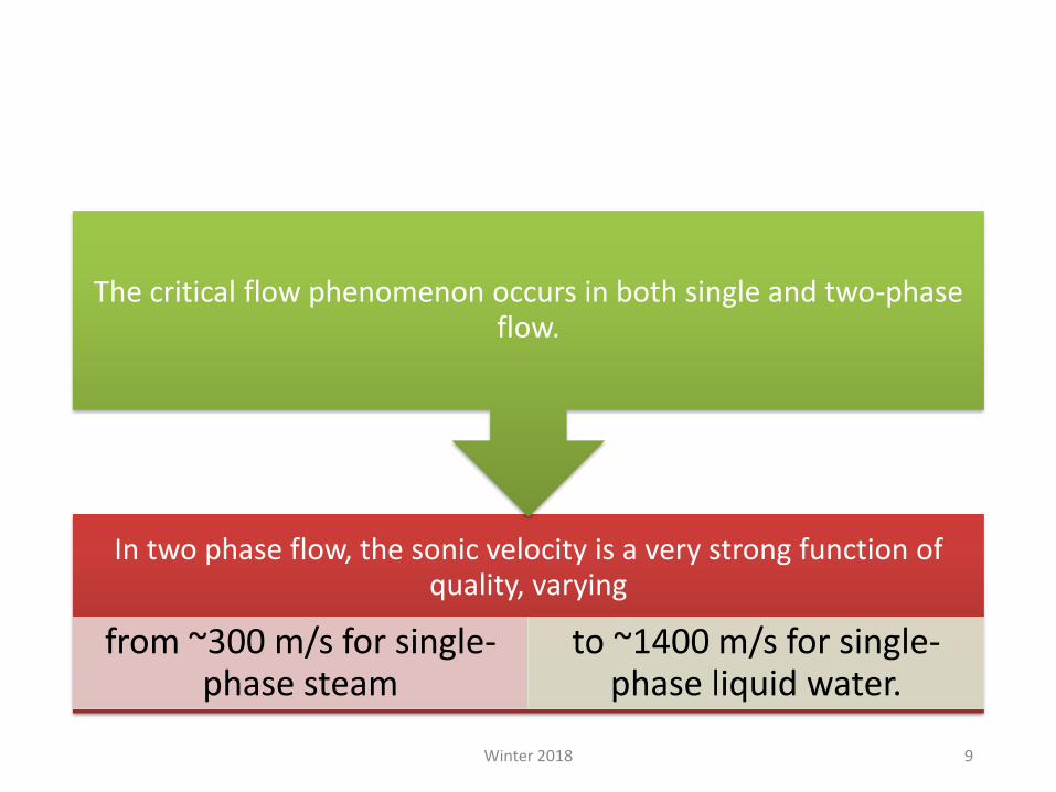
In two phase flow, the sonic velocity is a very strong function of quality, varying
from ~300 m/s for single-phase steam
to ~1400 m/s for single-phase liquid water.
The critical flow phenomenon occurs in both single and two-phase flow.

• For nuclear reactors, under postulated accident conditions such as large pipe break, two phase critical flows could occur and have been considered in safety analysis
• An evaluation of the flow rate in critical two-phase systems is therefore important for designing emergency cooling systems and for determining the extent and causes of damage in accidents.
Winter 2018 10
7.8 Water hammer
• Water hammer can result in equipment damage and can affect the performance or functionality of certain equipment
• It’s an important phenomenon, but in the context of this course, only basic information about water hammer is provided.
Winter 2018 11
7.8.1 Types of water hammer
• Two broad groups of water hammer events:
– water hammer events in single-phase liquid or gas, and
– two-phase water hammer events
• Most water hammer events in nuclear power plants fall into the first group and are caused by rapid acceleration or deceleration of single-phase liquid flowing in a piping system.
Winter 2018 12
Single-phase water hammer
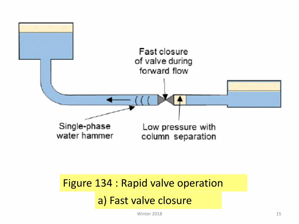
• Rapid acceleration of single-phase liquid flowing in a piping system can be created by rapid valve closure, …
• … which results in pressure waves that propagate in the piping system at sonic velocity.
Winter 2018 13
• Figure 134 (next) shows two examples of single-phase water hammer;
– Case A shows rapid valve closure causing water hammer.
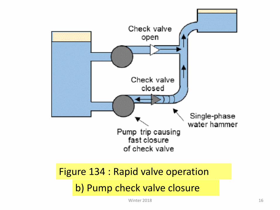
– Case B shows check-valve action downstream of a pump triggering water hammer
Winter 2018 14
15
Figure 134 : Rapid valve operation
a) Fast valve closure Winter 2018
16
b) Pump check valve closure
Figure 134 : Rapid valve operation
Winter 2018
Two-phase water hammer
• Two-phase water hammer events can be of several types.
• These events are more complex to analyze, have a strong impact on pump operation, and can cause significant damage to pipe components and pipe supports.
Winter 2018 17
Six scenarios lead to water hammer
Six transient scenarios lead to water hammer events with various probabilities and strengths, with most of them related to steam condensation-induced water hammer.
Winter 2018 18
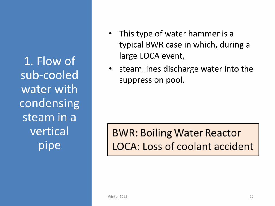
1. Flow of sub-cooled water with condensing steam in a
vertical pipe
• This type of water hammer is a typical BWR case in which, during a large LOCA event,
• steam lines discharge water into the suppression pool.
Winter 2018 19
As seen in Figure 135 (next slide)
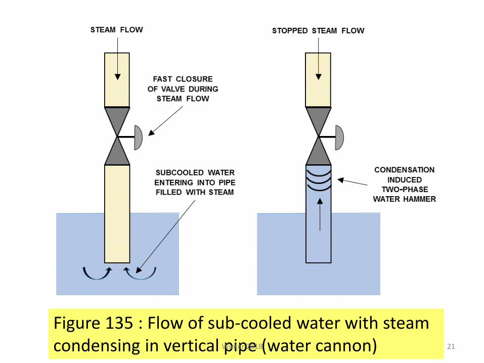
• If the valve is quickly closed or reduced significantly,
• a steam pocket remaining in the steam line can condense rapidly,
• which pulls water from the suppression pool towards the valve,
• thus creating water hammer
Winter 2018 20
21
Figure 135 : Flow of sub-cooled water with steam condensing in vertical pipe (water cannon) Winter 2018
2. Counter-current flow of
steam and water in a horizontal
pipe
• This situation occurs in PWR feedwater lines and in CANDU feeders.
• In horizontal stratified flow, a large interface area
exists between sub-cooled water and steam.
• Therefore, the steam flow is subjected to fast condensation, which induces an increase in steam flow from the upper pipe.
Winter 2018 22
As seen in Figure 136 (next slide)
• Under certain conditions, the counter-current flow can transition to slug flow and create a steam pocket.
• When the steam pocket collapses as a result of condensation, severe water hammer can occur.
Winter 2018 23
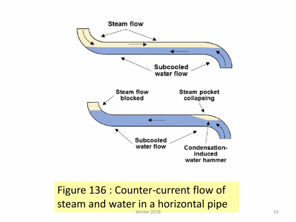
24
Figure 136 : Counter-current flow of steam and water in a horizontal pipe
Winter 2018
3. Pressurized
water entering a
vertical pipe filled
with steam
This type of water hammer can occur in any of the PWR and BWR reactors with refilling of a steam-filled pipe either from the bottom or from the top.
Winter 2018 25
• If pressurized sub-cooled water enters a pipe filled with steam in a piston flow regime, …
• … it can cause steam trapping.
• The filling rate for this situation is determined by the inertia of the liquid and the pressure induced by the pump or other refilling device.
Winter 2018 26
As seen in Figure 137 (next slide)
• Water hammer occurs in this situation if the refilling rate is higher than the bubble rise velocity for the top refilling case.
• This type of water hammer can also occur in CANDU reactors
Winter 2018 27
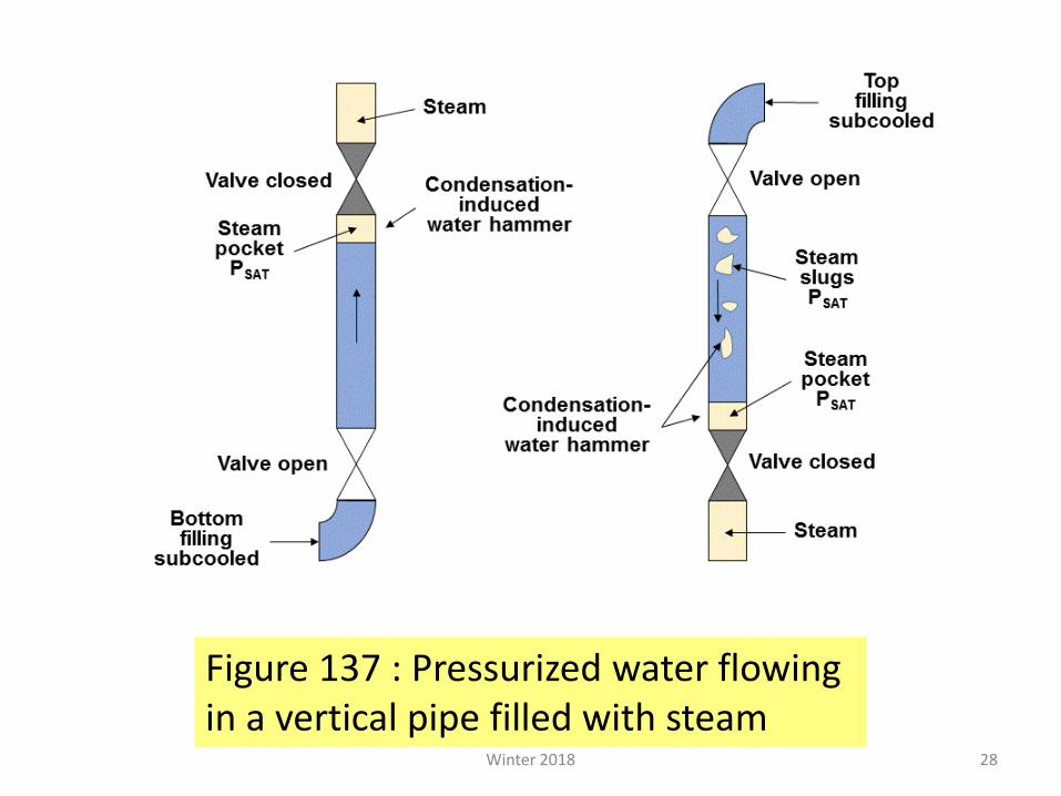
28
Figure 137 : Pressurized water flowing in a vertical pipe filled with steam
Winter 2018
4. Hot water
entering a low-
pressure line
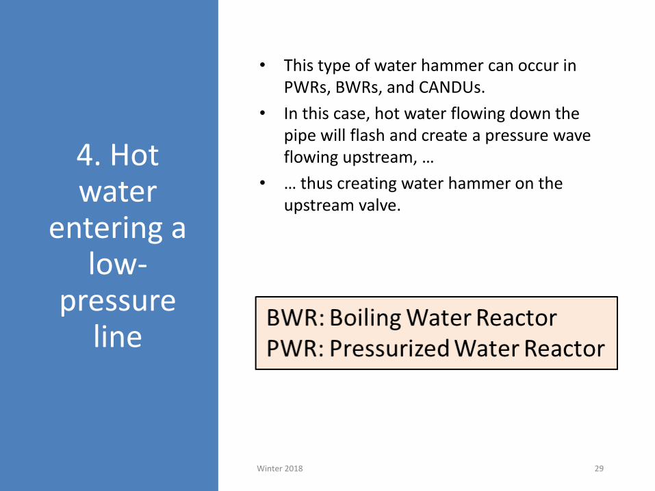
• This type of water hammer can occur in PWRs, BWRs, and CANDUs.
• In this case, hot water flowing down the pipe will flash and create a pressure wave flowing upstream, …
• … thus creating water hammer on the upstream valve.
Winter 2018 29
As seen in Figure 138 (next slide)
• The cold part of the sub-cooled water that was initially outside and below the pressure vessel can create water hammer on the downstream valve as it enters the steam-filled part of the pipe
Winter 2018 30
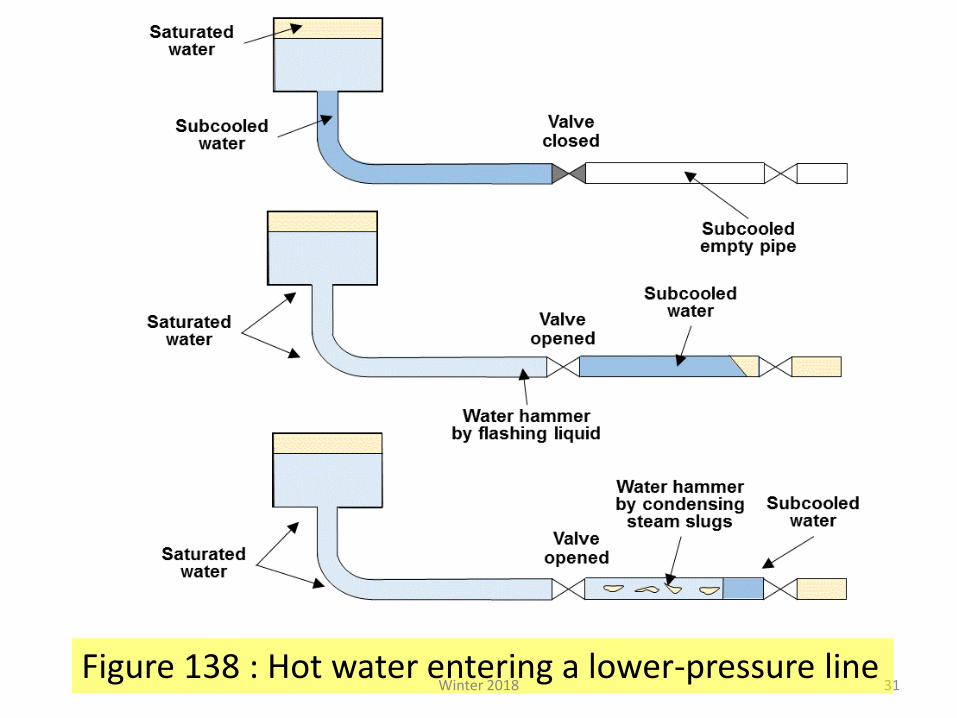
31Figure 138 : Hot water entering a lower-pressure line
Winter 2018
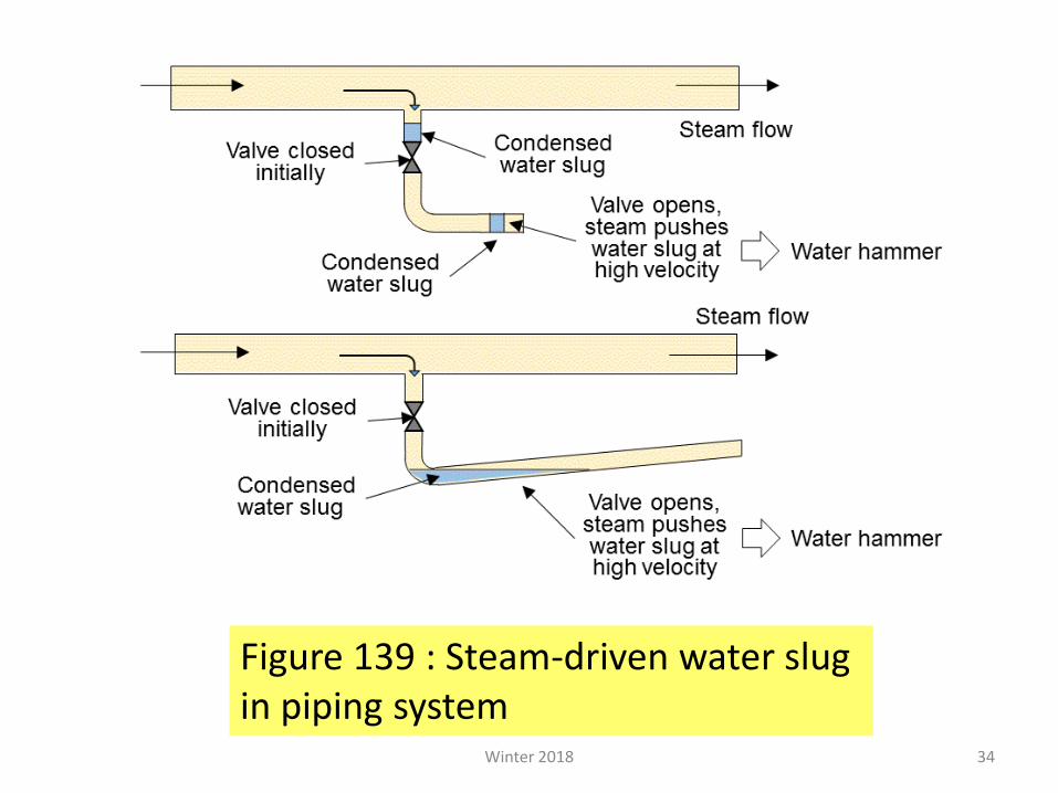
5. Water slug
driven by steam
• This type of water hammer can occur in a piping system that collects condensate upstream of a closed valve …
• … or can collect condensate in certain portions of the piping systems that are normally filled with steam.
Winter 2018 32
As seen in Figure 139 (next slide)
• Water hammer can occur when the valve opens and this steam drives the water slug at high speed.
• The slug can be accelerated significantly and can create a water hammer effect in a restricted part or at the closed end of the pipe
Winter 2018 33
34
Figure 139 : Steam-driven water slug in piping system
Winter 2018
6. Water filling a voided pipe line
35
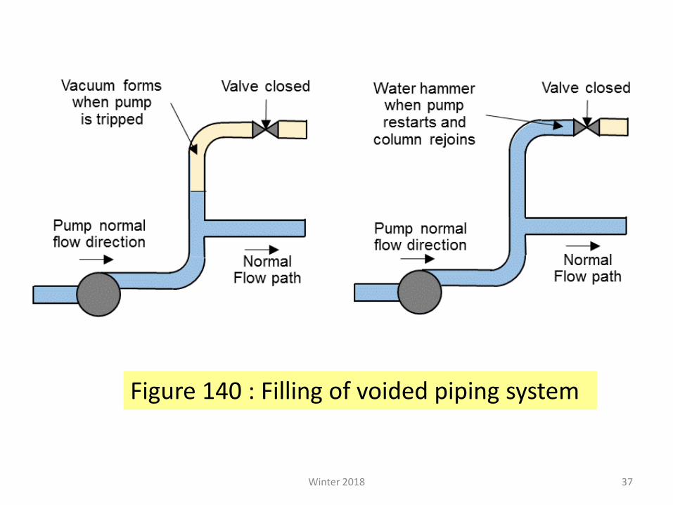
• In this situation (Figure 140), as a pump trips, …
• … water from the vertical section recedes downwards …
• … and creates an empty vacuum-filled space above.
Winter 2018
• When the pump restarts, …
• … it will push water to refill the pipe (and perhaps condense some residual steam),…
• … thus creating a significant water hammer
Winter 2018 36
37
Figure 140 : Filling of voided piping system
Winter 2018
7.9 Natural
circulation
New generations of nuclear reactor designs under development rely on passive systems, including use of natural circulation.
Winter 2018 38
All Generation IV reactors are required to make use of natural circulation as a heat transfer mechanism for removing heat from the reactor core, for some designs even under normal operating conditions.
Currently operating reactors are also required to use natural circulation to remove decay heat in accident situations when forced circulation in the core is lost
7.9.1 Natural circulation phenomenon
Winter 2018 41
Natural circulation will occur in a reactor primary
loop in the absence of pumped flow if …
… buoyant forces caused by differences in loop fluid densities are sufficient to
overcome the flow resistance of loop
components
Winter 2018 42
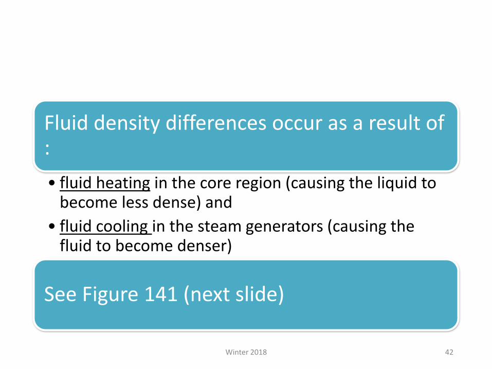
Fluid density differences occur as a result of :
• fluid heating in the core region (causing the liquid to become less dense) and
• fluid cooling in the steam generators (causing the fluid to become denser)
See Figure 141 (next slide)
43
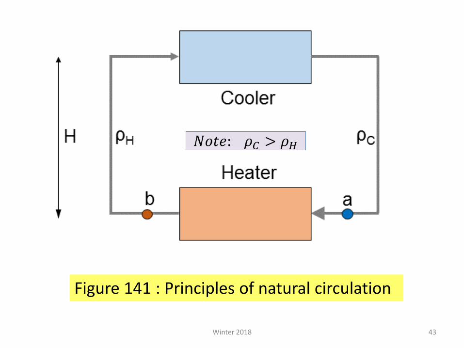
Figure 141 : Principles of natural circulation
Winter 2018
𝑁𝑜𝑡𝑒: 𝜌𝐶 > 𝜌𝐻
Natural circulation flow in a sub-cooled primary heat transport loop (such as in PWRs) is driven by :
• temperature-induced density gradients,
• enhanced by a thermal centre elevation difference between the hot (core) and cold (steam generator) regions in the primary loop.
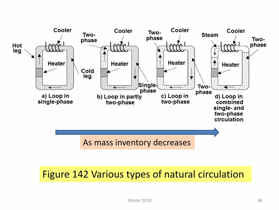
As seen in Figure 142
(next slide)
Such density gradient produces a buoyancy force that drives the natural circulation flow.
46
Figure 142 Various types of natural circulation
Winter 2018
As mass inventory decreases
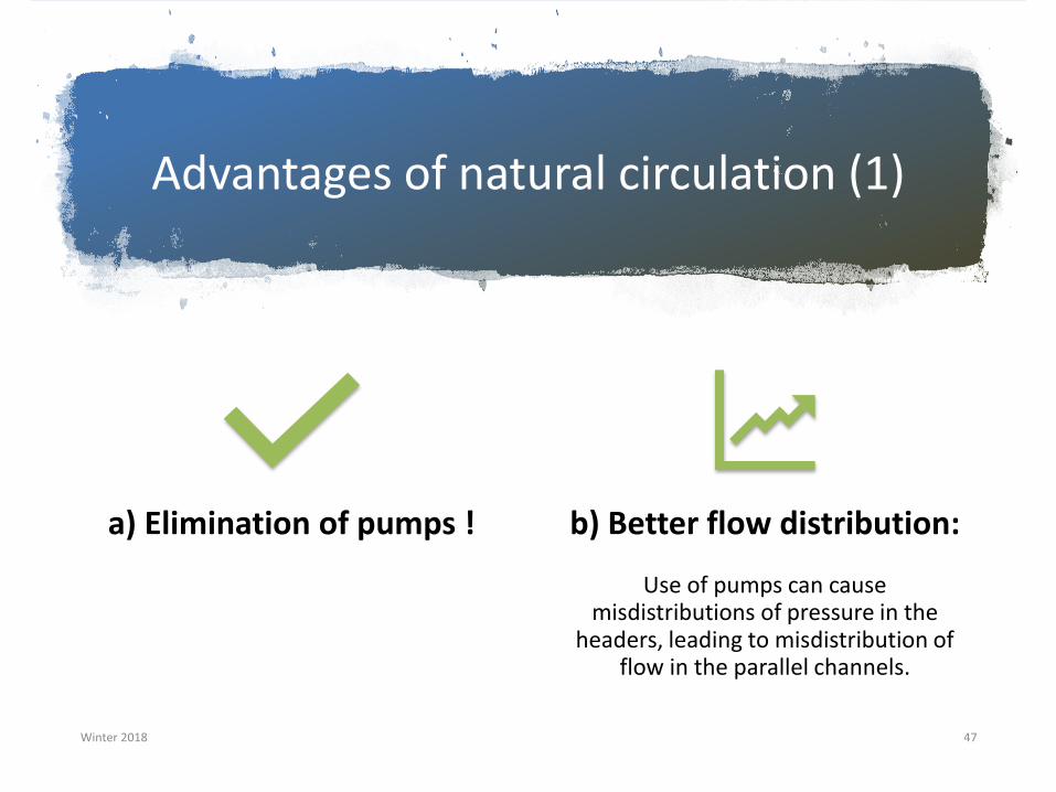
Advantages of natural circulation (1)
Winter 2018 47
a) Elimination of pumps ! b) Better flow distribution:
Use of pumps can cause misdistributions of pressure in the
headers, leading to misdistribution of flow in the parallel channels.
Moreover, using pumps requires orificing to provide flow in the fuel channels corresponding to each channel’s power.
Natural circulation provides a natural channel flow distribution.
Advantages of natural circulation (2)
c) Flow characteristics.
In a natural circulation system, flow increases with power, …
… whereas in a forced-circulation two-phase system, flow decreases with increasing power.
Winter 2018 49
Advantages of natural circulation (3)
d) Safety aspects.
Because natural circulation is based on a natural physical law, it is not expected to fail,
unlike fluid-moving machines such as pumps.
Winter 2018 50
Advantages of natural circulation (4)
e) Simplicity.
Because of the need to minimize pressure losses to enhance flow rates, …
… designers of natural circulation systems tend to eliminate all unnecessary pipe bends, elbows, etc.
The result is a system with a simple piping layout that can be fabricated in the factory.
Winter 2018 51
Challenges of natural circulation (1)
a) Low driving force:
This challenge has a specific impact on channel-type reactors such as CANDU.
As explained in this section, at low driving force in a CANDU, certain channels in the core may not sustain forward flow,
i.e., channel flow direction cannot be accurately estimated.
Winter 2018 52
Challenges of natural circulation (2)
b) Low system pressure losses.
With low driving force, the only way to obtain reasonably large flow rates is to design for low pressure losses, e.g.,:
❑ Use of large-diameter components and pipes
❑ Simplified system
❑ Elimination of components
Winter 2018 53
Challenges of natural circulation (3)
c) Low mass flux: The allowable maximum channel power is lower, leading to larger core volume.
Winter 2018 54
Challenges of natural circulation (4)
d) Instability effects:
Although instability is common to both forced and natural circulation systems, the latter are inherently less stable (see next slide)
Winter 2018 55
Instability effects (continued)
“Inherently less stable” due to the nonlinear nature of the natural circulation phenomenon, where any change in the driving force affects the flow, …
… which in turn affects the driving force, possibly leading to oscillatory behaviour.
Challenges of natural circulation (5)
• Low pressure and low-flow regime,
• where validated thermal-hydraulic relationships are not readily available.
Winter 2018 57
Challenges of natural circulation (6)
f) Specification of a start-up and operating procedure.
It is well known that most boiling systems exhibit instabilities at low pressures and low qualities.
Natural circulation reactors must be started up from a stagnant low-pressure, low-temperature
Start-up and operating procedure should avoid passing through an unstable zone
Winter 2018 58
Challenges of natural circulation (7)
g) Low CHF.
The basis for thermal margin is the CHF, which depends on geometric and operating parameters.
Since flow in natural circulation reactors is less, …
… designers of these reactors tend to use the maximum allowable exit quality to minimize their size.
Winter 2018 59
That means that the CHF value of the reactor tends to be significantly lower than in the forced circulation case.
This calls for several measures to increase CHF.
7.9.2 CANDU natural
circulation
Winter 2018 61
CANDU core cooling in the absence of forced flow (CCAFF), i.e., natural circulation, …
… has been extensively studied over the past 50 years.
CCAFF : Core cooling in the absence of forced flowThe CANDU CCAFF terminology defines the following natural circulation modes:
a) single-phase thermo-siphoning;
b) two-phase thermo-siphoning,
c) intermittent buoyancy-induced flow (IBIF), and continuous steam venting.
Winter 2018 62
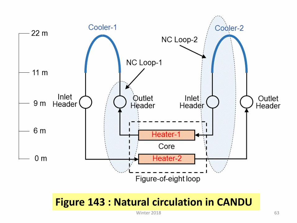
63
Figure 143 : Natural circulation in CANDU Winter 2018
Single-phase thermo-siphoning
Winter 2018 64
In this CCAFF mode, continuous heat input to
the coolant raises the temperature in the fuel
channel (as shown in Figure 143).
This induces a buoyancy force whereby the hot
liquid rises to the steam generator and deposits its
heat.
• From the steam generator, a lower-temperature (denser) liquid continues to flow down back to the core.
• In this case, the buoyancy forces are sufficient to overcome the static pressure caused by the elevation of the boilers with respect to the fuel channels.
• This is a continuous process and is capable of removing a substantial amount of decay heat indefinitely as long as …
• … the loop does not drain beyond about 70%, and …
• … as long as the heat is removed from the steam generators.
Two-phase thermo-
siphoning
• This is a similar phenomenon to liquid thermo-siphoning, but with continuous boiling of the liquid, …
• … and thus steam content in the flow provides an additional buoyancy force for heat transfer to the steam generators
– (resulting from the liquid-vapour density difference).
Winter 2018 67
It has been experimentally demonstrated that flow is still continuous in a given direction, with a large quantity of vapour at the channel outlet.
Winter 2018 69
For this thermo-siphoning mode, it is important to maintain a certain flow rate rather than a certain flow direction.
The flow rate in this type of natural circulation depends on the amount of void in the system and the channel power.
Intermittent buoyancy-induced flow (IBIF)
If the flow rate is reduced to a very small value, or if the fluid stagnates in the channel, the IBIF phenomenon occurs.
Winter 2018 70
Numerous analytical and experimental studies of IBIF have been conducted in recent decades to address the Canadian Nuclear Safety Commission-issued Generic Action Item GAI 90G02 on CCAFF.
The closure of this GAI provided answers to many issues related to fuel and fuel channel behaviour in a CANDU channel when the flow stops, such as:
– Role of static pressure (i.e., channel elevation);
– Location in the channel where boiling occurs;
– Vapour accumulation and outflow from the channel;
– Heat transfer from uncovered fuel elements;
– Impact of void rate generation;
– Fuel sheath temperature for uncovered fuel elements.
Winter 2018 72
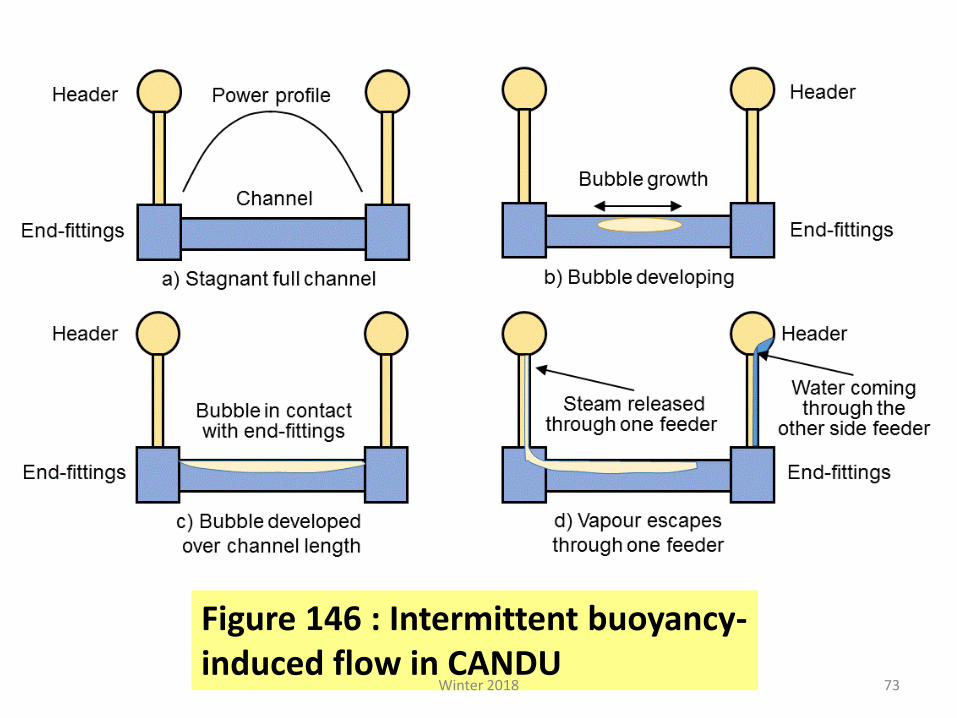
73
Figure 146 : Intermittent buoyancy-induced flow in CANDU
Winter 2018
Problems (Lecture 15)
15.1 Explain the reasons and consequences of water hammer in thermal-hydraulic equipment. Provide examples of possible water hammer situations in the CANDU heat transport systems, and indicate the strategies for mitigating the effects.
15.2 List the types of water hammer in CANDU heat transport system, and for each type list and explain the strategy for avoiding or mitigating it.
74Winter 2018
Problems (Lecture 15)(continued)
15.3 Explain the importance of natural circulation in the CANDU primary heat transport system, and the design decisions that help to enhance it.
15.4 Explain the key aspects of the Intermittent Buoyancy Induced Flow (IBIF) in CANDU channels, list and explain the key IBIFparameters.
75Winter 2018