Embed Size (px)
Citation preview
lable at ScienceDirect
Energy 172 (2019) 881e891
Contents lists avai
Energy
journal homepage: www.elsevier .com/locate/energy
Analysis of thermal and flow phenomena in natural circulation boilerevaporator
Sławomir Gradziel*
a r t i c l e i n f o
Article history:Received 25 September 2018Received in revised form24 January 2019Accepted 1 February 2019Available online 2 February 2019
Keywords:Power boilersMathematical modelEnergy balanceWaterwall tubesBoiler evaporator of a natural circulation
* Corresponding author. The Cracow University of Tmal Power Engineering, Al. Jana Pawła II 37, 31-864,
E-mail address: [email protected].
https://doi.org/10.1016/j.energy.2019.02.0030360-5442/© 2019 Elsevier Ltd. All rights reserved.
a b s t r a c t
An original in-house mathematical model enabling the analysis of thermal and flow phenomenaoccurring in the evaporator of a natural circulation boiler is proposed herein. It is a distributed parametermodel based on an original approach to the problem of solving the equations describing the principles ofmass, momentum, and energy conservation. The equations are solved using the method of lines. Spacederivatives are written on the left side of the equations and time derivatives are approximated usingdifference quotients. This system of ordinary differential equations is solved using the RungeeKuttamethod. Such an approach is characterised by high stability and accurate calculations. The developedmodel is applied to obtain the fluid mass flow, pressure, and enthalpy (temperature) values in the boilerevaporator. It can be applied in single- and two-phase flows. This paper presents the original results ofthe testing of the flow phenomena occurring in the boiler evaporator in steady and transient states.Steady-state tests were performed for different boiler loads. The operating multiplicity of the fluid cir-culation in the boiler evaporator was determined. A flow meter was installed on a downcomer, whichenabled a comparison between the measured values of the water mass flow and those calculated usingthe developed model. The presented model can also be applied for the analysis of the boiler evaporatoroperation at an abrupt increase or decrease in pressure in emergency situations. Such occurrences maycause water stagnation in the evaporator tubes; therefore, the tubes may crack.
© 2019 Elsevier Ltd. All rights reserved.
1. Introduction
Issues related to modelling transient thermal and flow phe-nomena occurring in a natural circulation boiler evaporator areattributed to their complex and strongly nonlinear characteristicsin many studies. The complexity results from many factors, such asthe high values of temperature and pressure, large surface areas ofheating surfaces, the fact that themodelling process has to considercomplex heat transfer processes occurring in the furnace chamber,local fouling of the waterwalls, configuration of burners, nonuni-form supply of air and fuel to the burner system, and two-phaseflow of the medium in the pipes. The nonlinearity is primarilycaused by the dependence of the thermal and physical properties ofwater, steam, and flue gases on pressure and temperature or ontemperature only.
The natural circulation of water in the boiler is possible due tothe difference between the density of the wateresteam mixture in
echnology, Institute of Ther-Krak�ow, Poland.
the risers and that of the water in the downcomers. This process isreferred to as circulation. In large boilers, waterwall tubes (risers)located in heating zones, together with downcomers in nonheatingareas with headers, comprise the circulation system or contour.Depending on the location, the circulation contours operate indifferent thermal load zones. Depending on the boiler design, theirnumber varies from a few to approximately a dozen. The validity ofthe evaporator operation depends on the device design, quality ofassembly, and the conditions in which the device operates.
The validity of water circulation in power boiler evaporators isthe subject of numerous studies aiming to ensure the reliability anddurability of the boiler components. In other words, their objectiveis to ensure a continuous and one-way water circulation in theevaporator tubes, ensuring that the evaporator is cooledappropriately.
A simplified lumped mass model of the boiler evaporator wasdefined previously [1,2]. However, the primary task of these studiesis to determine the optimal change in the temperature and pressureof the medium in the boiler evaporator that will shorten the boilerstart-up from the cold state.
It is noteworthy that water heaters (economisers), boiler evap-orators, and steam superheaters/reheaters with a complex
S. Gradziel / Energy 172 (2019) 881e891882
structure are still modelled using simple lumped parameter models[3,4] that are intended primarily to satisfy the needs of the boilerautomatic systems of regulation. This is due to the intricacies ofmathematically distributed parameter models. The advantage ofmodels with lumped thermal parameters is their short computa-tion time; meanwhile, the drawback is that excessive simplifica-tions are made.
Many studies are related to modelling steam superheaters andfeed water heaters. Some of them deserve special attention. Forexample, a distributed parameter model of a steam superheaterand the feed water heater was proposed in Refs. [5,6]. The model inRef. [5] was built using mass, momentum, and energy balanceequations. Because the thermal and physical properties of steam,water, and flue gas depend on temperature and pressure, or tem-perature only, the equations are nonlinear. In Ref. [6], the dynamicsof superheaters or economisers is modelled using simplifiedmodels based on the energy balance equation, omitting the equa-tions of the balance of mass and momentum. It is noteworthy thatthe applied mathematical models were verified experimentally bycomparing the results of measurements performed on a real facilityto those obtained from numerical computations. The models pro-posed in the studies mentioned above are one dimensional (1D).
Many studies concern the simulations of thermal and flowphenomena occurring in the supercritical boiler furnace chamberwaterwalls [7,8]. A distributed parameter mathematical model thatenables such simulations is proposed in Ref. [7]. It is a 1D modelbased on solving the equations describing the principles of mass,momentum, and energy conservation. They are solved usingappropriate difference schemes. The model is verified computa-tionally by comparing its results with those obtained from theanalytical solution for the transient state. Moreover, a comparisonwas also performed with the results obtained after solving thebalance equations using the CrankeNicolsonmethod. In both cases,excellent agreement was obtained between the results. The pro-posed model may also be used as an element of the power unitsimulator. A conjugate heat transfermodel was proposed in Ref. [8].A 1D model solution is proposed on the side of the working me-dium. In the waterwall finned tube, 20 control volumes are sepa-rated in each analysed cross section and equations of the three-dimensional (3D) transient-state heat transfer are written andsolved for them. The results of the developed 1D/3D model areverified by the simulation calculations of the furnace chamberwaterwalls installed in a supercritical boiler currently operating ina power station in Poland. Only the single-phase flow is consideredin the studies mentioned above, and the results obtained from thesimulation are not compared to the measurements.
2. Literature survey
The recent literature survey indicates that models of entireboilers or whole sub- and supercritical power plants are available.One example is [9], where Liu et al. developed a model of a 1000-MWonce-through boiler using neural networks. The model resultsare compared to those obtained from measurements performed ina real facility. The comparison concerns the output electric power,live steam pressure, and fluid temperature at the separator outlet. Itwas proven that previously used linear models can well predict theselectedworking points. However, that effectiveness becameworseif the models were used for a real installation in various operatingconditions. The obtained results indicate the considerable limita-tions of linear models in terms of their ability to represent thehighly nonlinear characteristics of the power plant dynamics.
A nonlinear approach to the problem of determining the me-dium enthalpy (temperature) between the water heater inlet andthe once-through boiler evaporator outlet is presented in Ref. [10].
The control of steam parameters, such as pressure and temperature,is necessary in power plants to ensure their full reliability. Steamparameters downstream the evaporator and upstream the waterheater should be controlled to obtain the required levels of load-dependent nominal values and to ensure that the boiler operatessmoothly. This is achieved by controlling the feed water supply tothe evaporator inlet and adjusting the mass flow according to thechanges in loads. A lumped parameter model of the evaporator isused in Ref. [10]. The model considers the energy balance equationonly.
The publications mentioned above concern simulations of theoperation of once-through boilers performed using models basedon considerable simplifications. One such simplification is by notconsidering the thermal load nonuniformity along the chamberheight or using a lumped parameter model of the evaporator.
Many studies are devoted to the analysis of the waterwall tubeoperation. Dhanuskodi et al. [11] applied a model using artificialneural networks to determine the temperature of the waterwalltube walls. The model considers the steady-state distributions ofpressure and temperature. The nonuniform distribution of loads isalso considered. Zheng et al. [12] developed a heat-transfer modelin spiral waterwall tubes. It is a distributed parameter model basedon the fluid's three-dimensional temperature field, calculatedtemperature of the wall, mass flow rate (mass flux) distribution,and thermal load of the walls. The same model is proposed inRef. [13]. Pan et al. [14] developed a model based on mass, mo-mentum, and energy conservation equations. The equations weresolved iteratively using the quasi-Newtonmethod, which producedthermoehydraulic characteristics of the boiler heating surfaces.
Many studies are related to designing general models of entirepower plants using commercial computer programs. Amodel of thedynamics of large power units was developed in Ref. [15]. TheAPROS software, developed by the VTT Technical Research Centre ofFinland in collaboration with the Fortum company, is used for thispurpose [16]. APROS includes two thermal hydraulic modules, i.e.the homogeneous and heterogeneous flow model. The homoge-neous model is applied for single-phase flows. For two-phase flows(evaporator, condensers), the APROS heterogeneous slip model isused. The high accuracy of the mathematical model applied in theAPROS software was confirmed in Refs. [17,18]. The developedmodel was verified against the power plant operating data.
An integrated model of a boiler in the steady state was devel-oped in Ref. [19]. It is composed of a few submodels, and a modifiedNewtoneRaphson method was used to obtain the numerical so-lutions of the equations in each submodel. Each heat transfer sur-face was regarded as a lumped-mass one. The input data for eachcomponent of the model, such as temperature, pressure, and massflow of the medium, were obtained from real installations. Theresults obtained from the model in steady-state conditions werecompared to the real data of a power plant.
Two-phase flows in power boilers have been emphasisedsignificantly in literature, for example in boiler evaporators. Boilerevaporators designed for subcritical parameters are characterisedby two-phase flows in the entire range of the power unit loads. Inthis respect, their operation is different compared to supercriticalboilers.
An open natural circulation cycle was proposed in Ref. [20] todesign a passive containment cooling system. A numerical codewas developed to simulate the process. It is used to analyse the flowcharacteristic in a small-scale model. The authors proposed asimplified scaling method that was verified through a comparativeanalysis. The scaling process was divided into heat-transfer scalingin the heat exchanger and pressure-loss scaling in risers anddowncomers. The open natural circulation cycle was tested on alaboratory stand. The circulation cycle additionally included a heat
S. Gradziel / Energy 172 (2019) 881e891 883
exchanger. The natural circulation cycle was modelled usingsimplified mass, momentum, and energy balance equations. Ahomogeneous model was assumed to calculate the pressure lossesin the two-phase flow.
A nonlinear dynamic model of a natural circulation evaporatorincluding a single boiler drum was presented in Ref. [21]. It is adistributed parameter model based exclusively on the fundamentalphysical laws of mass, momentum, and energy conservation. Thepresented approach tomodelling the boiler operationwas based onan analysis of the physical phenomena occurring in the boilerdrum, as well as in risers andwaterwall tubes. It also considered theboiler's unique design features. The model effectiveness was veri-fied by comparing its results with those obtained from a distributedcontrol system. As a simplification, a lumped parameter model wasused for outlet tubes and downcomers. An analysis was conductedto verify the model performance in irregularity conditions in theboiler operation. Special emphasis was placed on the impact of theirregularities on changes in the water level in the boiler drum. Thesimulation results were compared with the experimental results.Additionally, the simulation results were presented for other keyvariables of the boiler system that are typically difficult to measure.
A mathematical model based on mass and energy balanceequations for the water heater, boiler drum, and superheater waspresented in Ref. [22]. The results obtained from the model werecompared to those measured in a power plant. The temperatureand pressure values at the water heater and boiler drum outletwere analysed. The mean-square error (MSE) was calculated for thecomparisons. Analysis was not performed in the studies of evapo-rator circulation cycle or two-phase flows. The focus was on theparameters of steam at the boiler drum outlet.
It is noteworthy to focus on [23] that presents a mixed model ofa power plant operating in combinationwith a heat recovery steamgenerator. A simplified model of the boiler drum was used and thewater natural circulation in the system was analysed using theSPORTS code developed by Chatoorgoon [24]. A simplified algo-rithm was applied in the code to analyse a two-phase flow. Theresults of the proposed model of the boiler dynamics werecompared to the results obtained using two other models, i.e. themodel developed by Astrom and Bell [25] and that proposed byBhambare, Mitra, and Gaitonde [26]. The former is a lumpedparameter model. The latter is based on the basic equations of massand energy conservation, and on empirical correlations for two-phase flows. Neither of the publications considers or verifies theboiler operation to a greater extent, e.g. during the boiler start-up.The model proposed in Ref. [23] uses distributed parameters, andthe analysis concerns are one downcomer and one riser. The mass,momentum, and energy conservation equations are written suchthat time derivatives are used on their left side, whereas spacederivatives are used on the right. The authors suggest that such anonlinear system of equations should be solved using the availablenumerical codes. Themodel validation covers awide range of boileroperation, i.e. start-ups from cold and the hot states. The results arecompared to those obtained using the models described inRefs. [25,26].
3. Novelty of the present study
The performed literature survey indicates that no mathematicalmodels can describe the complex transient-state thermal and flowprocesses occurring in power boiler evaporators with adequateaccuracy.
Most studies do not pertain to distributed parameter models ethe analysis is typically performed using lumped parameter modelsthat are based on different forms of simplifications. Thus far, nonehave attempted to perform the experimental verification of the
mathematical heat-transfer models concerning the evaporatortubes of natural circulation boilers. A detailed analysis of theevaporator (downcomers and risers) operation is still lacking.Therefore, this paper presents a new mathematical modeldescribing the thermal and flow phenomena occurring in the boilerevaporator and the model is verified experimentally.
The proposed distributed parameter model is based on solvingbalance equations describing the principles of mass, momentum,and energy conservation, and enables an analysis of steady andtransient conditions processes. A system of appropriate ordinarydifferential equations is written with space derivatives on the leftside of the equation. The time derivatives on the right-hand side arereplaced with backward difference quotients. The system is solvedusing the RungeeKutta method. Such an approach is characterisedby high computational stability and accuracy. Owing to uniquemeasurements, the developed model of the boiler evaporator en-ables the determination of the pressure distribution, the mass flowrate and the dryness factor of steam, as well as thewater circulationmultiplicity in the evaporator.
A flow meter was installed in the downcomer to enable thetesting of natural circulation in the boiler evaporator. A series ofmeasurements were performed in a natural circulation boiler withan output of 210� 103 kg/h to verify the proposed method ofmodelling transient-state processes occurring in the boiler evapo-rator. Considering the current requirements related to the steampower boiler operation flexibility, the start-up and shutdown pro-cesses and rapid changes in loads, e.g. by opening the turbinevalves, should be performedwhilemaintaining the necessary levelsof natural circulation. Hence, the measuring points existing in thefacility were used. In some cases, some new ones were installed.The measurements were performed during the boiler acceptancetests after a general overhaul. The results obtained during the boilerstart-up, shutdown, and steady-state operation were compared tothe numerical calculation results.
A novel contribution of the current study is the developedmathematical model, which is characterised by its high stabilityand accuracy in performing calculations during rapid changes inthe boiler load. The results of the presented measurements are alsounique.
4. Mathematical model
This section presents the method of determining the distribu-tion of the fluid mass flow (mass flux), pressure (pressure drop),and enthalpy (temperature) along the furnace chamber waterwalltube. The relevant mass, momentum, and energy conservationequations are solved. The equations are derived in Ref. [27], and theexpressions presented below are their final forms:
� Mass conservation equation:
vr
vt¼ �1
Av _mvz
; (1)
� Momentum balance equation:
v _mvt
¼ �1A
v
vz
_m2
r
!� A
�vpvz
þ vpfvz
þ rg sin4�; (2)
� Energy balance equation:
S. Gradziel / Energy 172 (2019) 881e891884
vhvt
¼�1� 1
r
vpvh
��1� _mAr
�1r
vpvz
� vhvz
þ 1r
vpfvz
�þ _qU
Ar� 1Ar
vpvr
v _mvz
�(3)
After some simplifications and transformations, the balanceequations (1)e(3) can be written in a form where the space de-rivatives and time derivatives are obtained on the left and rightsides of the equations, respectively [27]:
v _mvz
¼ �Avr
vt; (4)
v
vz
_m2
A2rþ p
!¼ �1
Av _mvt
� vpfvz
� rg sin4; (5)
vhvz
¼ rA_m
�� vh
vtþ _qU
Ar
�(6)
The time derivatives on the right-hand side are replaced withbackward difference quotients. This system of ordinary differentialequations is solved using the RungeeKutta method.
After the changes above are introduced, the energy balanceequation is of the following form:
dhtjdz
¼rt�Dtj A
_mt�Dtj
�htj � ht�Dt
j
Dtþ _qUArt�Dt
j
!(7)
The fluid density is obtained as a function of enthalpy andpressure:
rtj ¼ f�hj; pt�Dt
j
�(8)
Solving the mass and momentum conservation equations, thefollowing are obtained, respectively:
d _mtj
dz¼ �A
rtj � rt�Dtj
Dt; (9)
ddz
0@�_m2�tj
A2rtjþ ptj
1A ¼ �1
A
_mtj � _mt�Dt
j
Dt� dpf
dz� rtj g sin4 (10)
The changes in the fluid temperature are obtained as a functionof enthalpy and pressure:
ttj ¼ f�htj ; ptj
�(11)
The subscript ‘j’ in equations 7e11 denotes the subsequentnumber of analysed cross sections and varies from j¼ 2 … M. Allthermophysical properties of the fluid are calculated online. Thesegment of the fluid flow path from the boiler drum to the down-comers and back to the drum through risers is divided into nodes.The first and last point of the circulation cycle, i.e. 1 and M, are thedowncomer and the riser nodes characterised by the same pres-sure, which is equal to the pressure value in the boiler drum. Theequality of pressure in two extreme nodes is obtained iterativelyusing the RegulaeFalsi method.
Moreover, the presented method requires that the Courantcondition should be satisfied [28]:
Dt � Dzw
(12)
The following data were assumed for the computations:
Dz¼ 0.5m and Dt¼ 0.02 s.This is a stability condition imposed on the time step to ensure
the transposition of the numerical solution with a velocity Dz/Dthigher than the physical velocity w.
The flow occurring in a natural circulation boiler evaporator is asingle- and a two-phase flow. The friction-related pressuredecrease in formula (10) is defined based on the DarcyeWeisbachequation, which is valid for the fluid from the evaporator inlet tothe point where the water reaches the saturation temperature:
dpfdz
¼ fdin
_mj _mj2rA2 (13)
where:
din e inner diameter of a duct with a circular cross section orequivalent diameter,f e friction factor.
The friction factor is extremely difficult to determine in amixture of water and steam. A number of mathematical modelshave been proposed to find the component being the effect offriction. The flow of the mixture can be considered as homoge-neous, or a slip flow model can be applied. Different models ofdetermination of pressure losses in two-phase flows are presentedin Ref. [29], and the obtained results are compared to each other.
The use of the homogenous model involves assuming that theproperties of the fluid are averaged for the entire mixture. Anotherassumption is that the velocity values of the gaseous and the liquidphase are the same, which implies that there is no slip between thephases. For the homogeneous model, the decrease in pressure dueto friction is defined by the following equation:
dpfdz
¼ fTPdin
G2
2rTP; (14)
where:
fTPe two-phase friction factor,Ge mass flux, kg/(m2s),rTP e two-phase density, kg/m3.
Classical relations, such as the Blasius formula, are used todetermine the friction factor. In this case, the Reynolds numberobtained for the averaged properties of the mixture is applied[30,31]:
ReTP ¼ G$dinhTP
; (15)
where
1hTP
¼ xhG
þ 1� xhL
; (16)
where:
hTP, hG, hL e dynamic viscosity of the homogenous mixture, thegaseous phase and the liquid phase, respectively,x e dryness factor.
The two-phase mixture density is obtained using the followingformula:
S. Gradziel / Energy 172 (2019) 881e891 885
rTP ¼ rL$rGxrL þ ð1� xÞrG
(17)
where:
rG, rLe density of the gaseous and the liquid phase, respectively.
Using slip models involves calculating the two-phase flowmultiplier that enables the friction-related pressure decrease to beobtained. The concepts included in this group are theLockharteMartinelli model, Friedel model, Chisholm model, andMartinellieNelson graphical method [31].
� The LockharteMartinelli model
To apply the LockharteMartinelli model the two-phase multi-pliers should be found. It makes it possible to determine thepressure gradient caused by frictional losses arising in the flow ofthe mixture [31]:
dpTPdz
¼ f2LdpLdz
(18)
The following formula is used to define the two-phase multi-plier used in equation (18):
f2L ¼ 1þ C
Xþ 1X2 (19)
The Martinelli parameter X appears in equation (19). It isdefined as
X ¼�1� xx
�0:9�rGrL
�0:5�hLhG
�0:1
(20)
The determination of the LockharteMartinelli multiplier isrelated to establishing the flow character of individual phases. Theparameter C is selected depending on whether the flow of thephases is laminar or turbulent (cf. Table 1).
The Friedel model was built using 25,000 measuring points. Themodel is applied for two-phase flows in vertical and horizontaltubes. The following formula is used to determine the two-phasemultiplier [31]:
f2LO ¼ E þ 3:24FH
Fr0:045We0:035(21)
Two-phase multiplier f2Lo is related to the flow of a mixture with
properties related to the properties of the liquid phase. CoefficientsE, F andH, as well as the Froude number (Fr) and theWeber number(We) in formula (21) are described in Ref. [31].
The Friedel model is recommended if the ratio between theliquid and gaseous phase dynamic viscosity is (hL/hG)� 1000. If thecondition is satisfied, equation (21) may be used in the entire rangeof the steam dryness factor values.
� The Chisholm Model
Table 1Values of parameter C.� The Friedel model
Liquid Gas C
turbulent turbulent 20viscous turbulent 12turbulent viscous 10viscous viscous 5
The Chisholmmodel is empirical. It can be used for a wide rangeof values of the dryness factor and steam pressure. The followingrelation is used to define the two-phase multiplier [31]:
f2LO ¼ 1þ
�Y2 � 1
�hBx0:5ð2�nÞð1� xÞ0:5ð2�nÞ þ x2�n
i; (22)
where:
Y2e the ratio betweenpressure gradients of the gaseous and theliquid phase in single-phase flowsB e mass flow rate (mass flux)-dependent coefficientn e exponent defining the coefficient of the flow resistance. Forthe Blasius formula, n¼ 0.25.
The methods of finding parameters Y2 and B are presented inRef. [31].
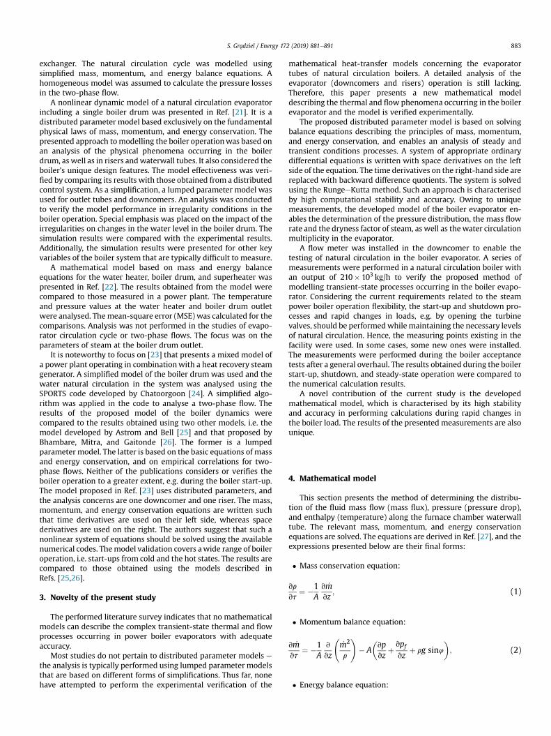
� The MartinellieNelson graphical method
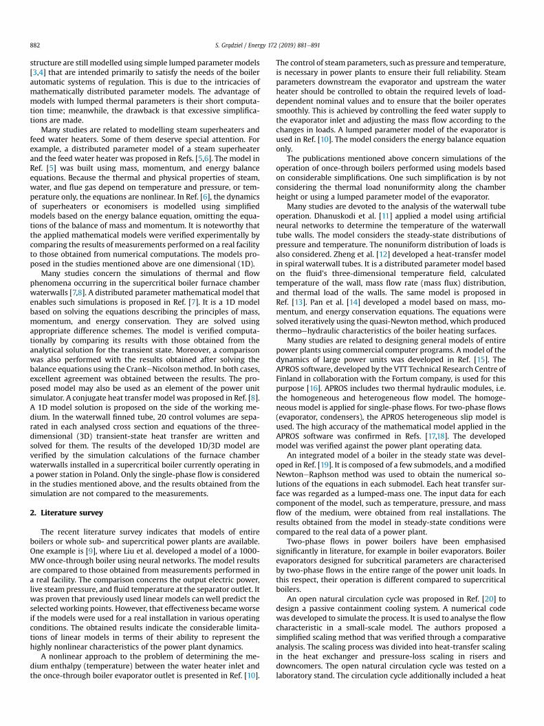
TheMartinellieNelsonmethodwas developed based on flows ofthe mixture of steam and water through horizontal pipes at pres-sure values ranging from 0.689 to 20.7MPa. The two-phasemultiplier needed to determine the losses arising due to frictionis read from a chart developed using different steam pressures anddifferent values of the dryness factor (x) (cf. Fig. 1). If pressure getshigher than the water critical point, the multiplier is f2
Loz1 [32].The two-phase multiplier read from the chart makes it possible to
Fig. 1. MartinellieNelson correlation [33].
S. Gradziel / Energy 172 (2019) 881e891886
determine the frictional decrease in pressure using the followingrelation:
dpfdz
¼ f2LOdpf ;LOdz
; (23)
where.
dpf ;LO
dz e friction-related losses in the flow of a two-phase mixturecharacterised by properties related to the liquid phase proper-ties, Pa/m.
5. Experimental verification
This section presents the experimental verification of thedeveloped model. First, the values of frictional losses arising in a210� 103 kg/h boiler waterwall tube and calculated using the ho-mogenous and the phase slip models presented herein arecompared. The experimental verification consists of comparing thecalculated and measured values of the water mass flow in thedowncomers and in obtaining the dryness factor and circulationmultiplicity. The numerical computations were performed usingin-house programs written in the Fortran language [34].
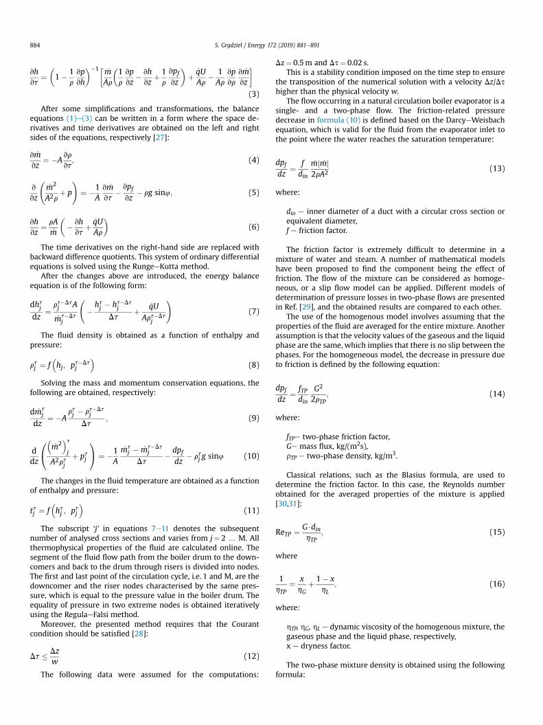
The water mass flow rate in the downcomer was measured in aboiler with the output of 210� 103 kg/h. It is a single-drum naturalcirculation boiler (cf. Fig. 2). The boiler generates high-pressure
Fig. 2. Diagram of the analysed natural circulation boiler with the output of210� 103 kg/h; KPP-1 e first stage of the steam superheater; KPP-2 e second stage ofthe steam superheater; KPP-3 e third stage of the steam superheater; ECO-1 e firststage of the economizer; ECO-2 e second stage of the economizer.
superheated steam fed into the power plant's primary duct. Theboiler rated output totals 210� 103 kg/h at the steam outlet pres-sure of 9.8MPa and temperature of 540 �C. The platen superheaterand the following stages of the steam superheaters are located inthe combustion gas bridge: 1st stage (KPP-1), 2nd stage (KPP-2)and 3rd stage (KPP-3). The two stages of the economizer (ECO-1and ECO-2), and a tubular-type air heater are placed in theconvective section. For verification, the boiler evaporator operationwas analysed during start-up, in the steady-state mode, and alsoduring the boiler acceptance tests. The acceptance tests were madeprior to the boiler re-commissioning after a general overhaul.
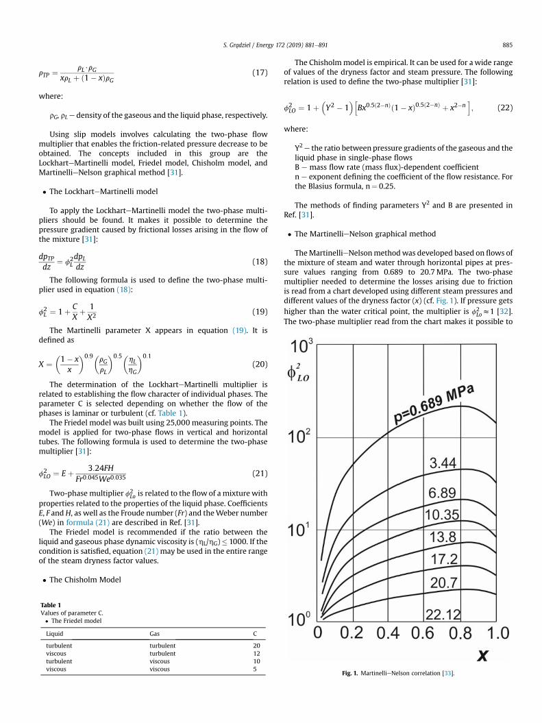
The steamewater system of the boiler evaporator comprises adrum, downcomers, risers, pipelines with fittings, and measuringinstruments. The boiler water flows from the drum into 10∅273� 25 downcomers through 54∅108� 10 tubes and continuesthrough four ∅130� 10 tubes to reach the waterwall tubes. Havingpassed through the waterwall tubes, the steamewater mixtureflows into the drum through ∅76� 10 tubes.
Fig. 3 presents a diagram of the analysed boiler circulationcontour with a marked point of the water mass flow measurementin the downcomer. The meter was installed at a height of approx-imately 10m. The method of meter fixing in the tube was describedin Ref. [35]. The boiler water was transferred from the drumthrough five ∅108� 10 tubes to a ∅273� 25 downcomer; subse-quently, from flowing through three ∅130� 10 tubes, it reachesinto the header followed by 30 ∅60� 5 waterwall tubes. Twelve∅76� 10 tubes carried the steamewater mixture into the drum.
The distribution of the thermal load along the waterwall tubes
Fig. 3. Diagram of the boiler evaporator with a marked point of the water mass flowmeasurement.
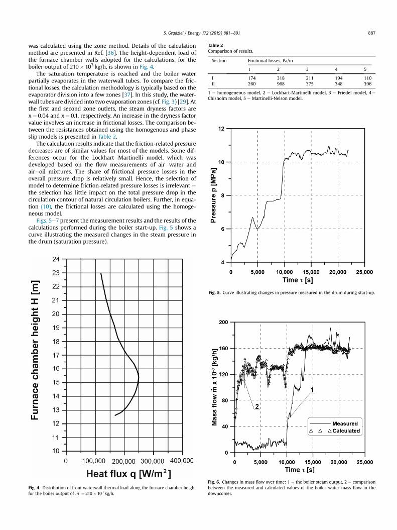
Table 2Comparison of results.
Section Frictional losses, Pa/m
1 2 3 4 5
I 174 318 211 194 110II 260 968 375 348 396
1 e homogeneous model, 2 e Lockhart-Martinelli model, 3 e Friedel model, 4e
Chisholm model, 5 e Martinelli-Nelson model.
S. Gradziel / Energy 172 (2019) 881e891 887
was calculated using the zone method. Details of the calculationmethod are presented in Ref. [36]. The height-dependent load ofthe furnace chamber walls adopted for the calculations, for theboiler output of 210� 103 kg/h, is shown in Fig. 4.
The saturation temperature is reached and the boiler waterpartially evaporates in the waterwall tubes. To compare the fric-tional losses, the calculation methodology is typically based on theevaporator division into a few zones [37]. In this study, the water-wall tubes are divided into two evaporation zones (cf. Fig. 3) [29]. Atthe first and second zone outlets, the steam dryness factors arex¼ 0.04 and x¼ 0.1, respectively. An increase in the dryness factorvalue involves an increase in frictional losses. The comparison be-tween the resistances obtained using the homogenous and phaseslip models is presented in Table 2.
The calculation results indicate that the friction-related pressuredecreases are of similar values for most of the models. Some dif-ferences occur for the LockharteMartinelli model, which wasdeveloped based on the flow measurements of airewater andaireoil mixtures. The share of frictional pressure losses in theoverall pressure drop is relatively small. Hence, the selection ofmodel to determine friction-related pressure losses is irrelevant ethe selection has little impact on the total pressure drop in thecirculation contour of natural circulation boilers. Further, in equa-tion (10), the frictional losses are calculated using the homoge-neous model.
Figs. 5e7 present the measurement results and the results of thecalculations performed during the boiler start-up. Fig. 5 shows acurve illustrating the measured changes in the steam pressure inthe drum (saturation pressure).
Fig. 4. Distribution of front waterwall thermal load along the furnace chamber heightfor the boiler output of _m ¼ 210� 103 kg/h.
Fig. 5. Curve illustrating changes in pressure measured in the drum during start-up.
Fig. 6. Changes in mass flow over time: 1 e the boiler steam output, 2 e comparisonbetween the measured and calculated values of the boiler water mass flow in thedowncomer.
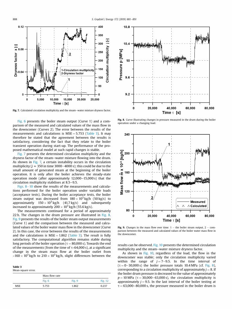
Fig. 7. Calculated circulation multiplicity and the steamewater mixture dryness factor.
Fig. 8. Curve illustrating changes in pressure measured in the drum during the boileroperation under a changing load.
Fig. 9. Changes in the mass flow over time: 1 e the boiler steam output, 2 e com-parison between the measured and calculated values of the boiler water mass flow inthe downcomer.
S. Gradziel / Energy 172 (2019) 881e891888
Fig. 6 presents the boiler steam output (Curve 1) and a com-parison of the measured and calculated values of the mass flow inthe downcomer (Curves 2). The error between the results of themeasurements and calculations is MSE¼ 5.753 (Table 3). It maytherefore be stated that the agreement between the results issatisfactory, considering the fact that they relate to the boilertransient operation during start-up. The performance of the pro-posed mathematical model at such rapid changes is stable.
Fig. 7 presents the determined circulation multiplicity and thedryness factor of the steamewater mixture flowing into the drum.As shown in Fig. 7, a certain instability occurs in the circulationmultiplicity (jz 350 in time 3000e4000 s); this could be due to thesmall amount of generated steam at the beginning of the boileroperation. It is only after the boiler achieves the steady-stateoperation mode (after approximately 12,000e15,000 s) that thecirculation multiplicity stabilises at 8.5e9.5.
Figs. 8e10 show the results of the measurements and calcula-tions performed for the boiler operation under variable loads(acceptance tests). During the boiler acceptance tests, the boilersteam output was decreased from 180� 103 kg/h (50 kg/s) toapproximately 150� 103 kg/h (41.7 kg/s) and subsequentlyincreased to approximately 200� 103 kg/h (55.6 kg/s).
The measurements continued for a period of approximately22 h. The changes in the drum pressure are illustrated in Fig. 8.Fig. 9 presents the results of the boiler steam output measurements(Curve 1) and the comparison between the measured and calcu-lated values of the boiler water mass flow in the downcomer (Curve2). In this case, the error between the results of the measurementsand the calculations is MSE¼ 1.862 (Table 3). The result is fullysatisfactory. The computational algorithm remains stable duringlong periods of the boiler operation (t¼ 80,000 s). Towards the endof the measurements (from the time of t~64,000 s), at a significantchange in the steam mass flow at the boiler outlet from~160� 103 kg/h to 210� 103 kg/h, slight differences between the
Table 3Mean-square error.
Mass flow rate
Fig. 6 Fig. 9 Fig. 12
MSE 5.753 1.862 0.237
results can be observed. Fig. 10 presents the determined circulationmultiplicity and the steamewater mixture dryness factor.
As shown in Fig. 10, regardless of the load, the flow in thedowncomer was stable; only the circulation multiplicity variedwithin the range of j¼ 7e9.5. In the time interval of(t¼ 0e30,000 s) the boiler pressure totals 10.4MPa (cf. Fig. 8),corresponding to a circulation multiplicity of approximately j¼ 8. Ifthe boiler drum pressure is decreased to the value of approximatelyp¼ 10MPa (t¼ 30,000e63,000 s), the circulation multiplicity isapproximately j¼ 9.5. In the last interval of the boiler testing att¼ 63,000e80,000 s, the pressure measured in the boiler drum is
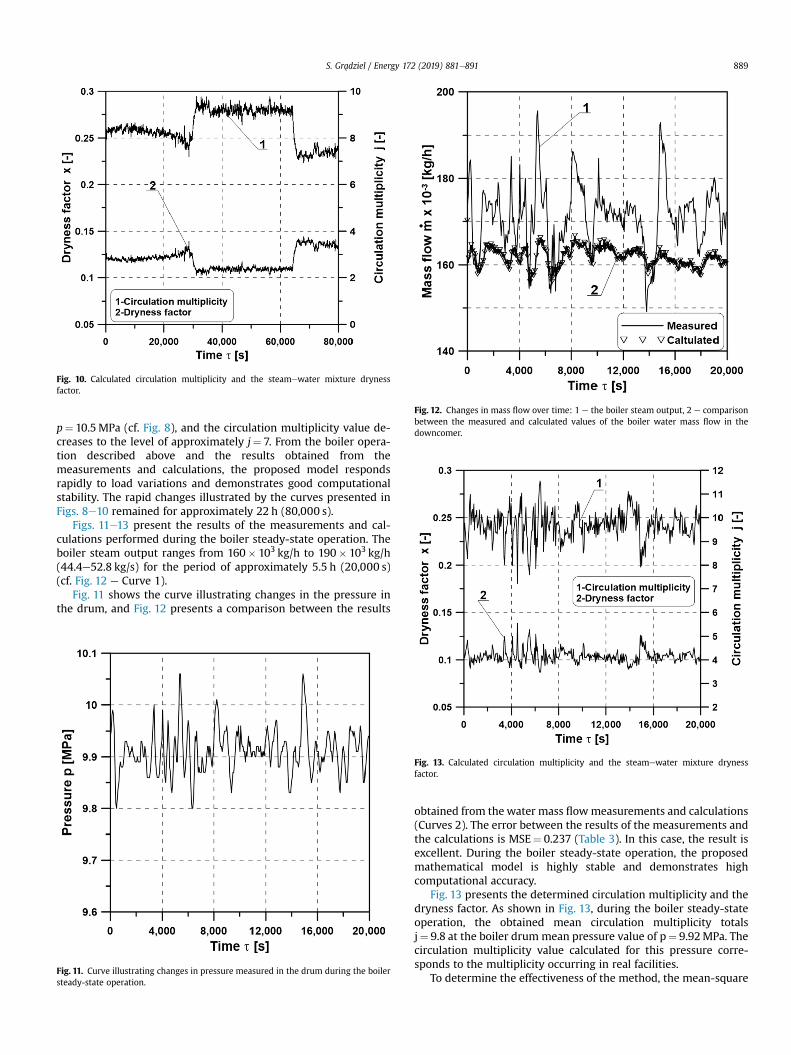
Fig. 10. Calculated circulation multiplicity and the steamewater mixture drynessfactor.
Fig. 12. Changes in mass flow over time: 1 e the boiler steam output, 2 e comparisonbetween the measured and calculated values of the boiler water mass flow in thedowncomer.
S. Gradziel / Energy 172 (2019) 881e891 889
p¼ 10.5MPa (cf. Fig. 8), and the circulation multiplicity value de-creases to the level of approximately j¼ 7. From the boiler opera-tion described above and the results obtained from themeasurements and calculations, the proposed model respondsrapidly to load variations and demonstrates good computationalstability. The rapid changes illustrated by the curves presented inFigs. 8e10 remained for approximately 22 h (80,000 s).
Figs. 11e13 present the results of the measurements and cal-culations performed during the boiler steady-state operation. Theboiler steam output ranges from 160� 103 kg/h to 190� 103 kg/h(44.4e52.8 kg/s) for the period of approximately 5.5 h (20,000 s)(cf. Fig. 12 e Curve 1).
Fig. 11 shows the curve illustrating changes in the pressure inthe drum, and Fig. 12 presents a comparison between the results
Fig. 11. Curve illustrating changes in pressure measured in the drum during the boilersteady-state operation.
Fig. 13. Calculated circulation multiplicity and the steamewater mixture drynessfactor.
obtained from the water mass flowmeasurements and calculations(Curves 2). The error between the results of the measurements andthe calculations is MSE¼ 0.237 (Table 3). In this case, the result isexcellent. During the boiler steady-state operation, the proposedmathematical model is highly stable and demonstrates highcomputational accuracy.
Fig. 13 presents the determined circulation multiplicity and thedryness factor. As shown in Fig. 13, during the boiler steady-stateoperation, the obtained mean circulation multiplicity totalsj¼ 9.8 at the boiler drum mean pressure value of p¼ 9.92MPa. Thecirculation multiplicity value calculated for this pressure corre-sponds to the multiplicity occurring in real facilities.
To determine the effectiveness of the method, the mean-square
S. Gradziel / Energy 172 (2019) 881e891890
error is calculated. The MSEs for the performed calculations andmeasurements were determined using the following relation:
MSE ¼ffiffiffiffiffiffiffiffiffiffiffiffiffiffiffiffiffiffiffiffiffiffiffiffiffiffiffiffiffiffiffiffiffiffi1n
Xni¼1
ðyi � ydtÞ2vuut (24)
where.
n e number of measurements; yi e measured value; ydt e ex-pected (calculated) value.The results were obtained from the calculations in Table 3.
The proposed model can be a useful tool for online monitoringthe thermal and flow processes occurring in the boiler pressureelements. It enables circulation control in the evaporator to preventwater stagnation in the boiler risers during fast changes in loads.Apart from monitoring flows through tubes, it is also possible tocontrol the thermal processes occurring in the furnace chamber.Such a system, using the presented model and water flow mea-surements in the boiler downcomers, is installed in a power plantin Poland. The start-up process is performed and controlled suchthat the appropriate levels of circulation in the evaporator areensured, thus enabling the levels to exceed the thermal stressesarising in the boiler thick-walled elements. The developed modelcan also be implemented in other steam-generating units in therange of sub- and supercritical pressure values.
6. Conclusions
The strict control of boiler evaporator operation is becomingincreasingly important. Therefore, there has been strong motiva-tion and growing interest towards the development of a mathe-matical model that can simulate the boiler evaporator performancenot only at the boiler constant load, but also in a wide range ofdynamic changes including start-ups and varying loads.
A mathematical model enabling the simulations of thermal andflow phenomena occurring in the evaporator of a natural circula-tion boiler was presented herein. It is a distributed parametermodel based on solving the equations describing the principles ofmass, momentum, and energy conservation. As proposed herein,the balance equations were solved using the RungeeKutta method.
The analysis of the calculations of friction-related losses per-formed in this study using different models enabled the differencesbetween the obtained results to be observed. The differences werethe effect of the different approaches to the two-phase flowmultiplier determination. In the analysed conditions of the two-phase flow in the natural circulation boiler evaporator, consid-ering the evaporator pressure, the circulation multiplicity was high(jz 10); consequently, the dryness factor of the steamewatermixture at the drum inlet was small. This implied that in thistype of flow, the friction-related pressure decreasewas significantlysmaller than the sum of the two other quantities comprising thetotal pressure decrease, i.e. the sum of the hydrostatic pressuredrop and the decrease resulting from the change in the twoephasemixture momentum. In this situation, the accuracy of the methodof the friction-related constituent determination is negligible. Inthis study, frictional pressure losses in the two-phase flow weredetermined using a homogenous model.
The developed method was verified experimentally. The naturalcirculation in the evaporator of a boiler with the steam output of210� 103 kg/h was tested. The tests were performed during theboiler start-up and shutdown, and during the boiler steady-stateoperation. The calculation results were compared to the measure-ment results, and a fully satisfactory agreement was obtained.
The developed mathematical model can be used to simulatethermal and flow phenomena occurring in both evaporators ofnatural circulation boilers and supercritical once-through boilers.
References
[1] Taler J, Weglowski B, Taler D, Sobota T, Dzierwa P, Trojan M, Madejski P,Pilarczyk M. Determination of start-up curves for a boiler with natural cir-culation based on the analysis of stress distribution in critical pressure com-ponents. Energy 2015;92:153e9.
[2] Taler J, Dzierwa P, Taler D, Harhut P. Optimization of the boiler start-up takinginto account thermal stresses. Energy 2015;92:160e70.
[3] Chaibakhsh A, Ghaffari A, Moosavian SAA. A simulated model for a once-through boiler by parameter adjustment based on genetic algorithms. Simu-lat Model Pract Theor 2007;15:1029e51.
[4] Li H, Huang X, Zhang L. A lumped parameter dynamic model of the helicalcoiled once-through steam generator with movable boundaries. Nucl Eng Des2008;238:1657e63.
[5] Zima W. Simulation of dynamics of a boiler steam superheater with anattemperator. Proc IME J Power Energy 2006;220:793÷801.
[6] Zima W. Mathematical modelling of transient processes in convective heatedsurfaces of boilers, Forschung im Ingenieurwesen, vol. 71. Springer Verlag;2007. p. 113e23.
[7] Zima W, Nowak-Ocło�n M, Ocło�n P. Simulation of fluid heating in combustionchamber waterwalls of boilers for supercritical steam parameters. Energy2015;92:117e27.
[8] Zima W, Nowak-Ocło�n M. Novel online simulation-ready models of conjugateheat transfer in combustion chamber waterwall tubes of supercritical powerboilers. Energy 2018;148:809e23.
[9] Liu XJ, Kong XB, Hou GL, Wang JH. Modeling of a 1000 MW power plant ultrasuper-critical boiler system using fuzzy-neural network methods. EnergyConvers Manag 2013;65:518e27.
[10] Backi ChJ. Nonlinear modeling and control for an evaporator unit. Contr EngPract 2018;78:24e34.
[11] Dhanuskodi R, Kaliappan R, Suresh S, Anantharaman N, Arunagiri A,Krishnaiah J. Artificial Neural Networks model for predicting wall tempera-ture of supercritical boilers. Appl Therm Eng 2015;90:749e53.
[12] Zheng S, Luo Z, Zhou H. Distributed parameter modeling and thermal analysisof a spiral water wall in a supercritical boiler. Therm Sci 2013;17:1337e42.
[13] Shu Z, Zixue L, Yanxiang D, Huaichun Z. Development of a distributed-parameter model for the evaporation system in a supercritical W-shapedboiler. Appl Therm Eng 2014;62:123e32.
[14] Pan J, Wu G, Yang D. Thermal-hydraulic calculation and analysis on water wallsystem of 600 MW supercritical CFB boiler. Appl Therm Eng 2015;82:225e36.
[15] Starkloff R, Alobaid F, Karner K, Epple B, Schmitz M, Boehm F. Developmentand validation of a dynamic simulation model for a large coal-fired powerplant. Appl Therm Eng 2015;91:496e506.
[16] VTT. APROS simulation software. Available from: http://www.apros.fi.[17] Alobaid F, Starkloff R, Pfeiffer S, Karner K, Epple B, Hyun-Gee Kim.
A comparative study of different dynamic process simulation codes forcombined cycle power plants e part A: part loads and off-design operation.Fuel 2015;153:692e706.
[18] Alobaid F, Starkloff R, Pfeiffer S, Karner K, Epple B, Hyun-Gee Kim.A comparative study of different dynamic process simulation codes forcombined cycle power plants e part B: start-up procedure. Fuel 2015;153:707e16.
[19] Hajebzadeh H, Ansari Abdulhamid NM, Niazi S. Mathematical modeling andvalidation of a 320MW tangentially fired boiler: a case study. Appl Therm Eng2019;146:232e42.
[20] Guoa X, Sun Z, Wang J, Yu S. Scaling analyses for the open flashing-drivennatural circulation system. Nucl Eng Des 2017;324:111e21.
[21] Sedi�c A, Katuli�c S, Pavkovi�c D. Dynamic model of a natural water circulationboiler suitable for on-line monitoring of fossil/alternative fuel plants. EnergyConvers Manag 2014;87:1248e60.
[22] Sreepradha Chandrasekharan, Chandra Panda Rames, SwaminathanBhuvaneswari Natrajan. Mathematical model for integrated coal fired thermalboiler using physical laws. Energy 2017;118:985e98.
[23] Sunil PU, Barve Jayesh, Nataraj PSV. Mathematical modeling, simulation andvalidation of a boiler drum: some investigations. Energy 2017;126:312e25.
[24] Chatoorgoon V. SPORTS - a simple non-linear thermalhydraulic stability code.Nucl Eng Des 1986;93(1):51e67.
[25] Astrom KJ, Bell RD. Drum-boiler dynamics. Automatica 2000;36:363e78.[26] Bhambare KS, Mitra SK, Gaitonde UN. Modeling of a coal-fired natural cir-
culation boiler. J Energy Resour Technol 2007;129(2):159e67.[27] Gradziel S, Majewski K. Simulation of heat transfer in combustion chamber
waterwall tubes of supercritical steam boilers. Chem Process Eng 2016;37(No.2):199e213.
[28] Gerald CF, Wheatley PO. Applied numerical analysis. California PolytechnicState University, Addison-Wesley Publishing Company; 1994.
[29] Gradziel S, Majewski K. Calculations of the pressure drop in the natural cir-culation boiler evaporator. In: MATEC web of conferences, vol. 240; 2018.https://doi.org/10.1051/matecconf/201824005009. 05009.
[30] Hetsroni G. Red., handbook of multiphase system. McGraw-Hill Book
S. Gradziel / Energy 172 (2019) 881e891 891
Company; 1982.[31] Hewitt G, Shires G, Bott T. Process heat transfer. CRC Press, Begell House;
1994.[32] Martinelli RC, Nelson DB. Prediction of pressure drop during forced circulation
boiling of water. Trans Am Soc Mech Eng 1948;70(6):695e702.[33] Dziubi�nski M, Prywer J. Two-phase fluid mechanics (in Polish). Warszawa:
WNT; 2009.[34] Fortran PowerStation 4.0. Microsoft developer studio. Palo Alto, CA: Microsoft
Corporation; 1995.[35] Zima W, Gradziel S. Simulation of transient processes in heating surfaces of
power boilers. LAP LAMBERT Academic Publishing; 2013.[36] Gradziel S. Heat load determination of boiler furnace chamber. Arch Combust
2015;35(No 2):75e88.[37] Kuznetsov NW, Nitor WW, Dubovski IE, Karasina ES. Thermal calculations of
steam boilers. Standard method (in Russian). Moscow, Russia: Energy; 1973.
Nomenclature
A: surface area, m2
d: diameter, mFr: Freund number, dimensionlessf: friction factor, dimensionlessg: gravitational acceleration, m/s2
G: mass flux, kg/(m2s)H: furnace chamber height, mh: enthalpy, J/kgj: circulation multiplicity factor, dimensionlessMSE: mean-square error, dimensionless_m: mass flow, kg/sp: pressure, Pa
q: heat flux, W/m2
Re: Reynolds number, dimensionlesst: temperature, �CU: perimeter, mw: velocity, m/sWe: Weber number, dimensionlessX: Martinelli parameter, dimensionlessx: dryness factor, dimensionlessz: axial coordinate, m
Greek letters
Dt: time step, sDz: control volume length, mh: dynamic viscosity, Pa,s4: tube inclination angle, degf: two-phase multiplierr: density, kg/m3
t: time, s
Subscript
f : frictionG: gaseousin: innerj: control volume numberL: liquidTP: two-phase