Embed Size (px)
Citation preview
C-DOT GPON
LCT USER MANUAL
CENTRE FOR DEVELOPMENT
OF TELEMATICS
System Practices
Section No. 770-027-0976
Issue 03, November 2014
C-DOT GPON
LCT USER MANUAL
© 2014, C-DOT Printed in India

C-DOT GPON
LCT USER MANUAL
ISSUE 03
NOVEMBER 2014
KARTIKA 2071
SERIES 000 : OVERVIEW
CSP SECTION NO. 770-027-0976
THIS C–DOT SYSTEM PRACTICE REFERS TO THE C–DOT GIGABIT PASSIVE
OPTICAL NETWORK (ABBREVIATED AS C-DOT GPON) IN THE REST OF THIS
PUBLICATION).
THE INFORMATION IN THIS SYSTEM PRACTICE IS FOR INFORMATION
PURPOSES AND IS SUBJECT TO CHANGE WITHOUT NOTICE.
A COMMENT FORM HAS BEEN INCLUDED AT THE END OF THIS
PUBLICATION FOR READER'S COMMENTS. IF THE FORM HAS BEEN USED,
COMMENTS MAY BE ADDRESSED TO THE DIRECTOR (C & S ), CENTRE FOR
DEVELOPMENT OF TELEMATICS, MANDI ROAD, MEHRAULI, NEW DELHI -
110 030
COPYRIGHT
2014 Centre for Development of Telematics (C-DOT). All rights reserved. No part of this document may be reproduced in any form without the prior written permission of the copyright owner.

Table of Contents
Preface ........................................................................................................................................................................................ 4
Chapter 1. Introduction to Local Craft Terminal ................................................................................................................. 5
1.1. Purpose ....................................................................................................................................................... 5
1.2. Style Conventions ........................................................................................................................................ 5
1.3. Function of Command Buttons ................................................................................................................ 5
1.4. Presentation of Settable and Non-settable Attributes ............................................................................ 7
Chapter 2. Preparing to Use GPON Software ....................................................................................................................... 8
2.1. Installing the Software on a PC or Laptop Computer ........................................................................... 8
2.2. Starting up GPON LCT Software ............................................................................................................ 8
2.3. Exception ................................................................................................................................................... 12
Chapter 3. Communicating with a GPON Network Element ........................................................................................ 14
3.1. Introduction ............................................................................................................................................... 14
3.2. Establishing Communication with a Network Element ...................................................................... 14
Chapter 4. Commissioning a GPON LCT Network Element ......................................................................................... 15
4.1. Introduction ............................................................................................................................................... 15
4.2. Condition of the Craft Terminal before it can be used ........................................................................ 15
4.3. Identification of the NE on the Network .............................................................................................. 15
4.4. Installation of the NE ............................................................................................................................... 16
4.5. Security Management ................................................................................................................................ 17
4.6. software Download ................................................................................................................................... 23
4.7. Configuration Management ..................................................................................................................... 33
4.8. Connection Management ......................................................................................................................... 60
4.9. Performance Management ....................................................................................................................... 75
4.10. Log Management ....................................................................................................................................... 92
4.11. Fault Management ..................................................................................................................................... 98
4.12. Help ................................................................................................................................................... 104
H:\HOME\GPON\UTL\User\GPON-LCT-user-manual-I03.doc November 7, 2014

Preface
This is a general introduction of GPON Software. It explains the various functions supported by the software. It explains the style conventions, summarizes the function of command buttons and check boxes, and explains how settable and non-settable attributes are presented. It also includes a list of abbreviations and document references.
LCT USER MANUAL 5
Chapter 1.
Introduction to Local Craft Terminal
This document gives a general overview for the Local Craft Terminal (hereafter referred as LCT) of GPON system. It gives the flow of the process initiated from the clicking of the icon to start the application to the features as provided by the whole system.
LCT is for directly accessing administration, configuration, maintenance, performance, faults, and system status data for one NE at a time.
1.1. PURPOSE
The purpose is to show how to use the GPON LCT software application during the commissioning, alarm configuration, testing and maintenance of GPON network elements as well as how to trouble-shoot alarms from GPON equipment.
1.1.1. Assumptions made about the User’s Knowledge:
GPON LCT software is a independent program. Users of this software are assumed to have a basic knowledge of OS, for example, how to navigate, how to close/move , etc.
1.2. STYLE CONVENTIONS
Arial font and bold typeface are used for names of, for instance, windows, operation, fields, and push buttons when these names appear on the screen (example: The GPON LCT window).
Arial font and bold and italic typeface are used to give user some additional necessary information about the software.
SM Chip Resistor (PB Free) Courier New Font gives the examples related to the various functions performed by the GPON LCT Software.
Arrows are used for indicating the menu structure in instructions on how to select a certain menu item
For Example: To select Security option under the menu item Security, Select � Security.
1.3. FUNCTION OF COMMAND BUTTONS
The command buttons are those that are found along the bottom of a window. These buttons and their functions are described below:
Cancel is used to discard any changes made in the window, and closes the window.
Chapter 1.
6 C-DOT GPON
Help is used to launch the on-line help for the window question.
Print is used to print the attributes in the window.
Close is used to close the current window.
Start is used to start any Monitoring or Reporting on system side.
Add is used to add selection into the shown table.
Delete is used to send Delete request or to delete any row of shown table.
Get is used to send Get request.
Set : Is used to send Set request .
Refresh is used to refresh the data in the current window.
Ok is used to send selected configuration request ( get or set )
Modify is used to modify the value/attribute of current window.
INTRODUCTION TO LOCAL CRAFT TERMINAL
LCT USER MANUAL 7
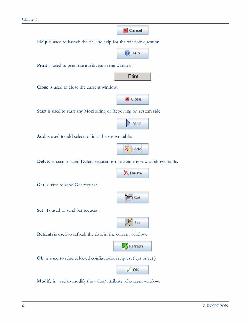
Register is used to register the New ONT to the System.
Commit is used to commit the software image to the system.
1.3.1. User Input options
Combo Box : Is used to Select any item given in list.
Check Box : Is used to Select or Deselect the item.
Radio Buttons : Is used to select any one item of given list.
Text Box : Is used to write any text.
1.4. PRESENTATION OF SETTABLE AND NON-SETTABLE ATTRIBUTES
1.4.1. Settable Attributes
The value of a settable attribute is always shown on a white background. When a window is first opened, the value presented on a white background is the current value of the attribute (read directly from the NE). This attribute is settable, that is, the user can change it. Highlighting the current attribute value and then entering the new value directly in the field usually does this.
1.4.2. Non-settable Attributes
The value of a non-settable attribute is always shown on a grayed-out background. When a window is first opened, the value presented on the grayed-out background is the current value of the attribute (read directly from the NE). The user cannot change this attribute.
Note: Only Super User can change the values of settable attributes.
8 C-DOT GPON
Chapter 2.
Preparing to Use GPON Software
2.1. INSTALLING THE SOFTWARE ON A PC OR LAPTOP COMPUTER
The procedures that are associated with getting ready to use the LCT software to communicate with the NE of interest are:
Step Action
1 Log on to Windows
2 Insert disk1 of GPON LCT Software in CD Drive
3 Double-click on the My Computer icon.
4 Double-click on CD Drive
5 Double-click Setup.
The user will be guided through the setup procedure and prompted to supply information if the default settings are not suitable.
2.2. STARTING UP GPON LCT SOFTWARE
After GPON LCT has been installed (see Section 1.1 Installing the Software on a PC or a Laptop Computer), it can be started up as follows:
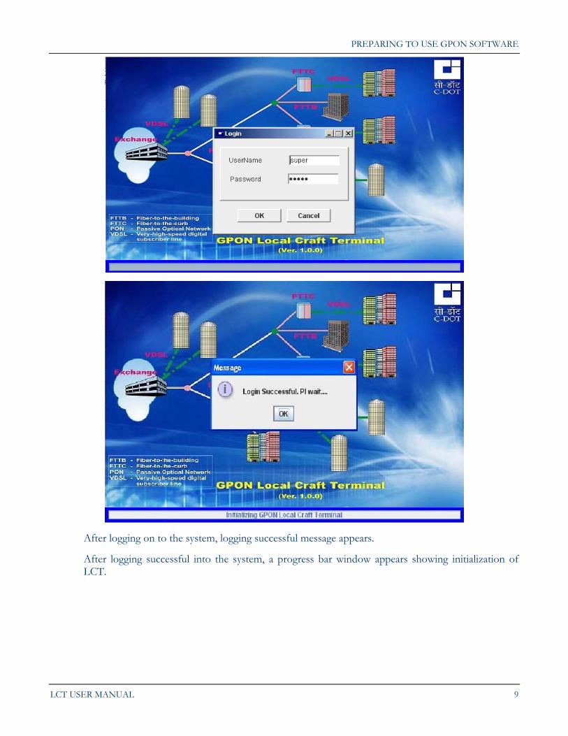
Step1> double-click the icon of the GPON System. As soon as the icon is clicked a splash screen with login screen appears. A user has the facility of logging on to NE.
PREPARING TO USE GPON SOFTWARE
LCT USER MANUAL 9
After logging on to the system, logging successful message appears.
After logging successful into the system, a progress bar window appears showing initialization of LCT.
Chapter 2.
10 C-DOT GPON
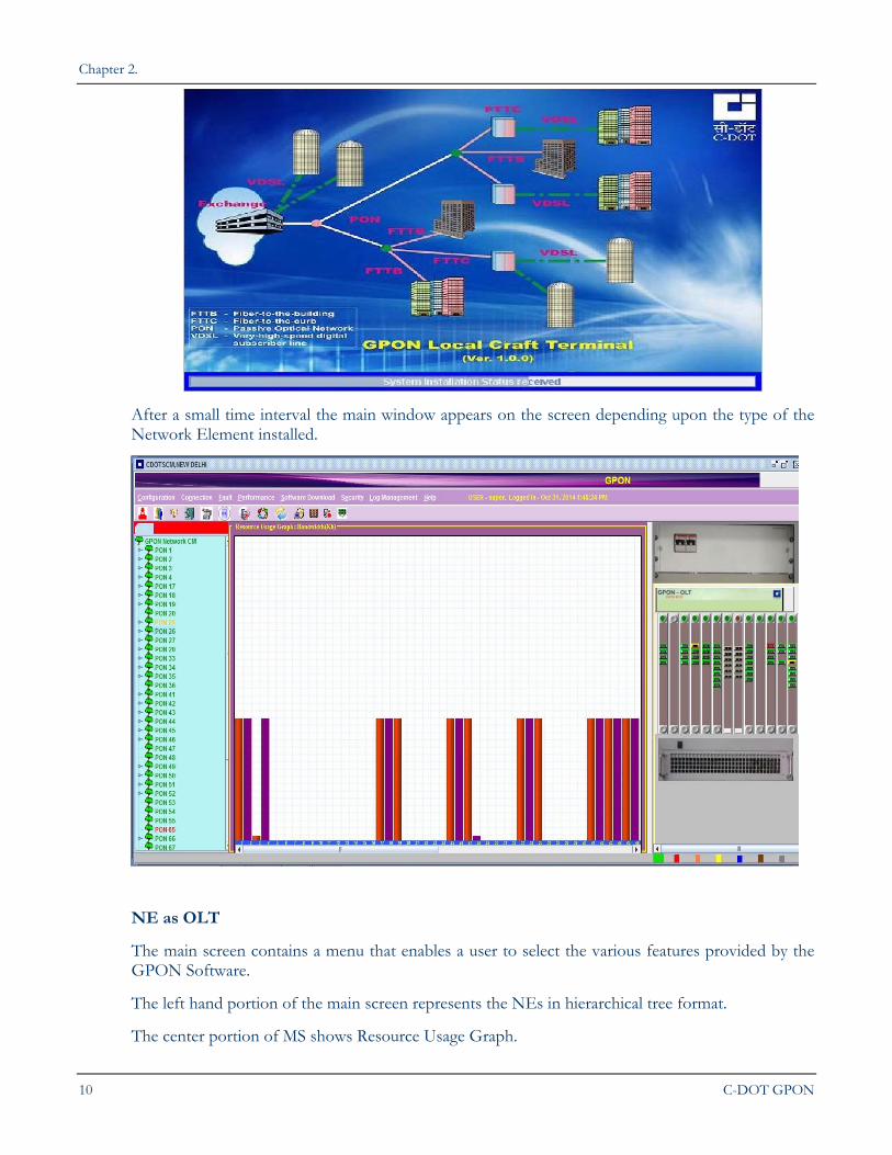
After a small time interval the main window appears on the screen depending upon the type of the Network Element installed.
NE as OLT
The main screen contains a menu that enables a user to select the various features provided by the GPON Software.
The left hand portion of the main screen represents the NEs in hierarchical tree format.
The center portion of MS shows Resource Usage Graph.
PREPARING TO USE GPON SOFTWARE
LCT USER MANUAL 11
The right hand portion of the main screen contains the pictorial representation of the front view of the Network Element.
The color of the cards gives the status of those cards in the NE.
The various card colors can be categorized as:
Green Color: The card is a healthy card. This means that no alarms are present in the card.
Red Color: The card contains at least one Critical alarm.
Orange Color: The card contains at least one Major alarm.
Yellow: Card is in Link Down, state or at least one minor alarm is present in the card.
Gray: Card is absent in the slot.
Blue: Device is in missing state.
Brown: The card is in jacked in/initializing/passive state.
The toolbar provides the user with the option of choosing certain operations without selecting the menu.
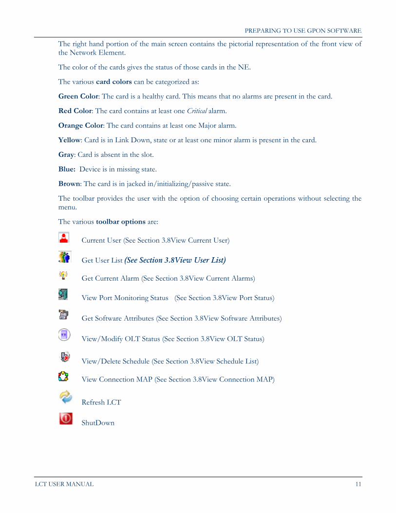
The various toolbar options are:
Current User (See Section 3.8View Current User)
Get User List (See Section 3.8View User List)
Get Current Alarm (See Section 3.8View Current Alarms)
View Port Monitoring Status (See Section 3.8View Port Status)
Get Software Attributes (See Section 3.8View Software Attributes)
View/Modify OLT Status (See Section 3.8View OLT Status)
View/Delete Schedule (See Section 3.8View Schedule List)
View Connection MAP (See Section 3.8View Connection MAP)
Refresh LCT
ShutDown
Chapter 2.
12 C-DOT GPON
Note: Before logout and exit, user must ensure that all the earlier requests have been completed.
A detailed description of the functions supported by these toolbar options is described under the sections given in the brackets.
To view which version of the software is currently running select Help > About GPON LCT
The user can now access the various attributes supported by the GPON Software.
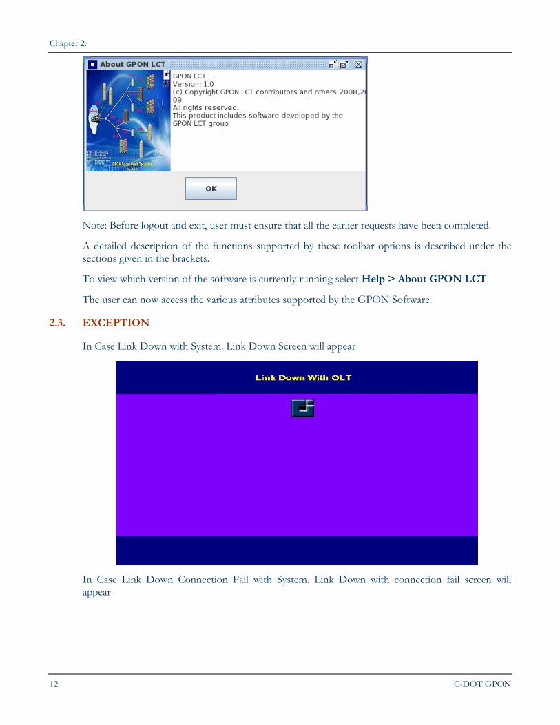
2.3. EXCEPTION
In Case Link Down with System. Link Down Screen will appear
In Case Link Down Connection Fail with System. Link Down with connection fail screen will appear
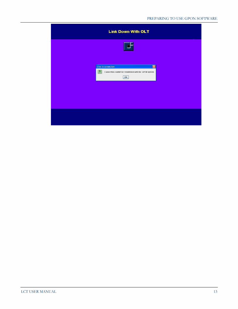
PREPARING TO USE GPON SOFTWARE
LCT USER MANUAL 13
14 C-DOT GPON
Chapter 3.
Communicating with a GPON Network Element
3.1. INTRODUCTION
The following procedures are associated with establishing communication with a Network Element (hereafter referred to as NE):
3.2. ESTABLISHING COMMUNICATION WITH A NETWORK ELEMENT
What is a “local” NE?
A GPON network element that is directly connected via a RJ-452 cable to a PC or laptop computer running GPON Software is called NE in GPON Software.
To physically connect a PC or laptop to network element, the user should the following steps:
Step 1> Connect one end of the RJ-45 cable to a Ethernet port of the computer.
Step 2> Connect the other end of the RJ-45 cable of the LCT outlet socket on the SCM Card of the ATCA sub rack of GPON.
If GPON software is installed on the computer, the user is now in a position to establish direct communication with the GPON in question.
LCT USER MANUAL 15
Chapter 4.
Commissioning a GPON LCT Network Element
4.1. INTRODUCTION
Before the user can use GPON Network Elements in a telecommunications network, certain configuration procedures are necessary. These procedures are sometimes referred to as pre-configuration procedures .The following topics are covered:
Condition of the Craft Terminal before it can be used.
Identification of the NE on the network
Setting the NE’s Clock
User Management
Transporting Data Files
Configuring the Physical Equipment(NE)
Status Check
Filter Setting of Alarms
Performance Monitoring within a C-GPON NE
Forceful Switching of Laser
Setting of Maintenance Parameters
4.2. CONDITION OF THE CRAFT TERMINAL BEFORE IT CAN BE USED
Once the software has been installed and is running on a computer, and the computer has been physically linked to a NE, the user can establish communication with it. In all the pre-configuration procedures we presume that we have established communication with the NE to which the LCT is connected.
4.3. IDENTIFICATION OF THE NE ON THE NETWORK
This section deals with the identification of a NE in a telecommunications network as a unique piece of equipment.
Chapter 4.
16 C-DOT GPON
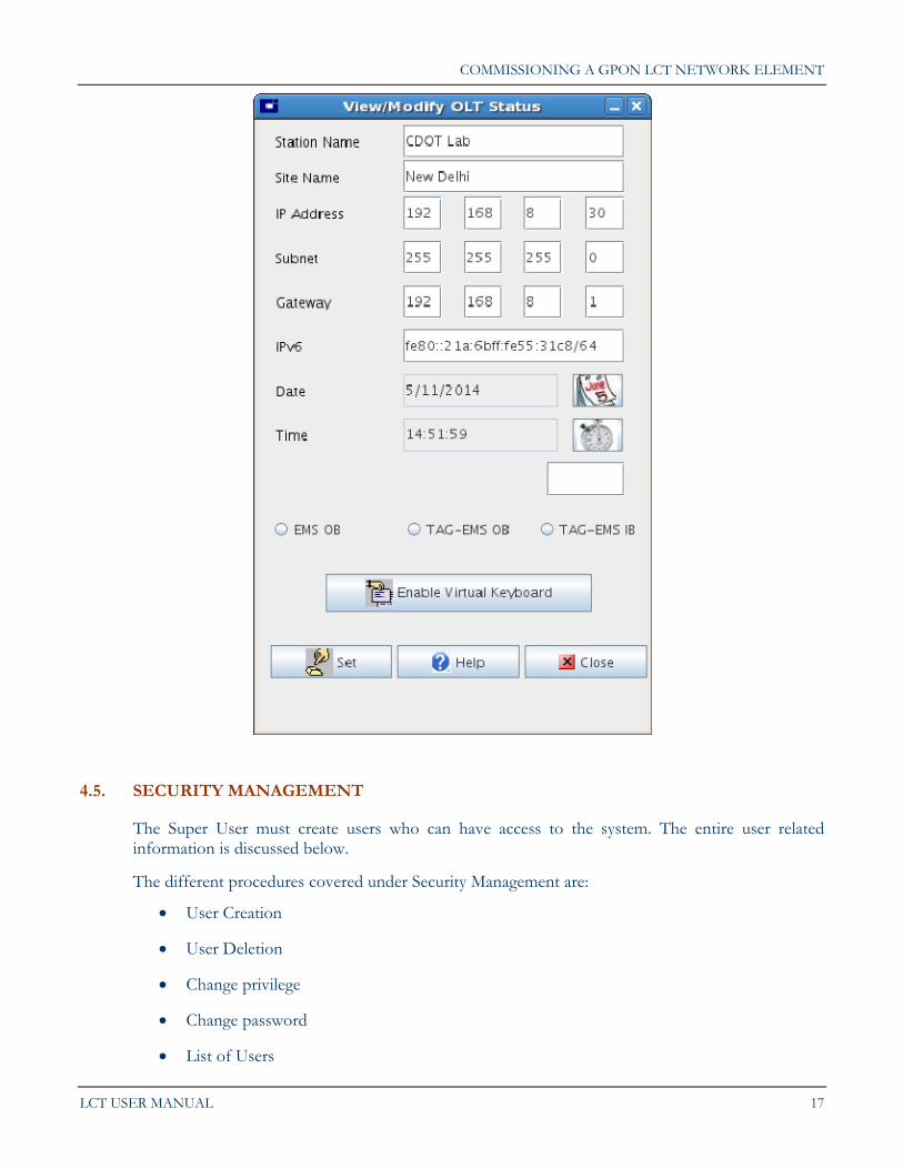
4.4. INSTALLATION OF THE NE
When the NE is not installed, then a window pops up displaying a message that NE is not Installed, when the user logs in to the system.
The following installation parameters should be assigned to a NE at the time of installation:
A Station name and Site name (this enables the user to give the NE a name that is easy to locate geographically)
An IP address (this is the NE’s IP address )
A Subnet Mask
A Gateway
Date and Time
IPV6 Address if needed
COMMISSIONING A GPON LCT NETWORK ELEMENT
LCT USER MANUAL 17
4.5. SECURITY MANAGEMENT
The Super User must create users who can have access to the system. The entire user related information is discussed below.
The different procedures covered under Security Management are:
User Creation
User Deletion
Change privilege
Change password
List of Users
Chapter 4.
18 C-DOT GPON
Current logged User
View security Log
Log Out
4.5.1. User Creation
Only Super User can create a User.
To create a user, the following steps should be followed:
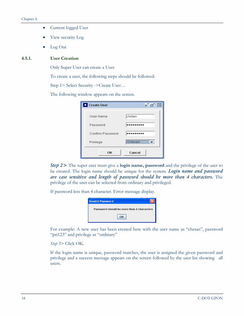
Step 1> Select Security ->Create User…
The following window appears on the screen.
Step 2> The super user must give a login name, password and the privilege of the user to be created. The login name should be unique for the system. Login name and password are case sensitive and length of password should be more than 4 characters. The privilege of the user can be selected from ordinary and privileged.
If password less than 4 character. Error message display.
For example: A new user has been created here with the user name as “chetan”, password “pri123” and privilege as “ordinary”
Step 3> Click OK.
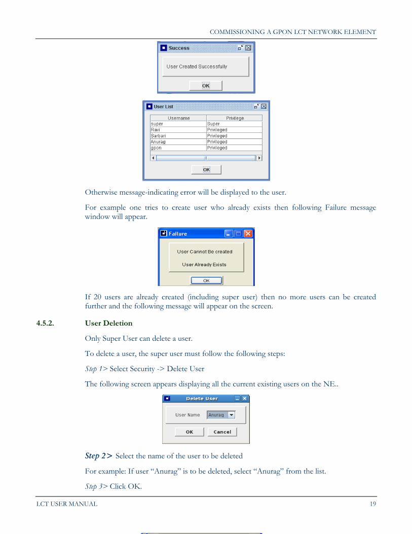
If the login name is unique, password matches, the user is assigned the given password and privilege and a success message appears on the screen followed by the user list showing all users.
COMMISSIONING A GPON LCT NETWORK ELEMENT
LCT USER MANUAL 19
Otherwise message-indicating error will be displayed to the user.
For example one tries to create user who already exists then following Failure message window will appear.
If 20 users are already created (including super user) then no more users can be created further and the following message will appear on the screen.
4.5.2. User Deletion
Only Super User can delete a user.
To delete a user, the super user must follow the following steps:
Step 1> Select Security -> Delete User
The following screen appears displaying all the current existing users on the NE..
Step 2> Select the name of the user to be deleted
For example: If user “Anurag” is to be deleted, select “Anurag” from the list.
Step 3> Click OK.
Chapter 4.
20 C-DOT GPON
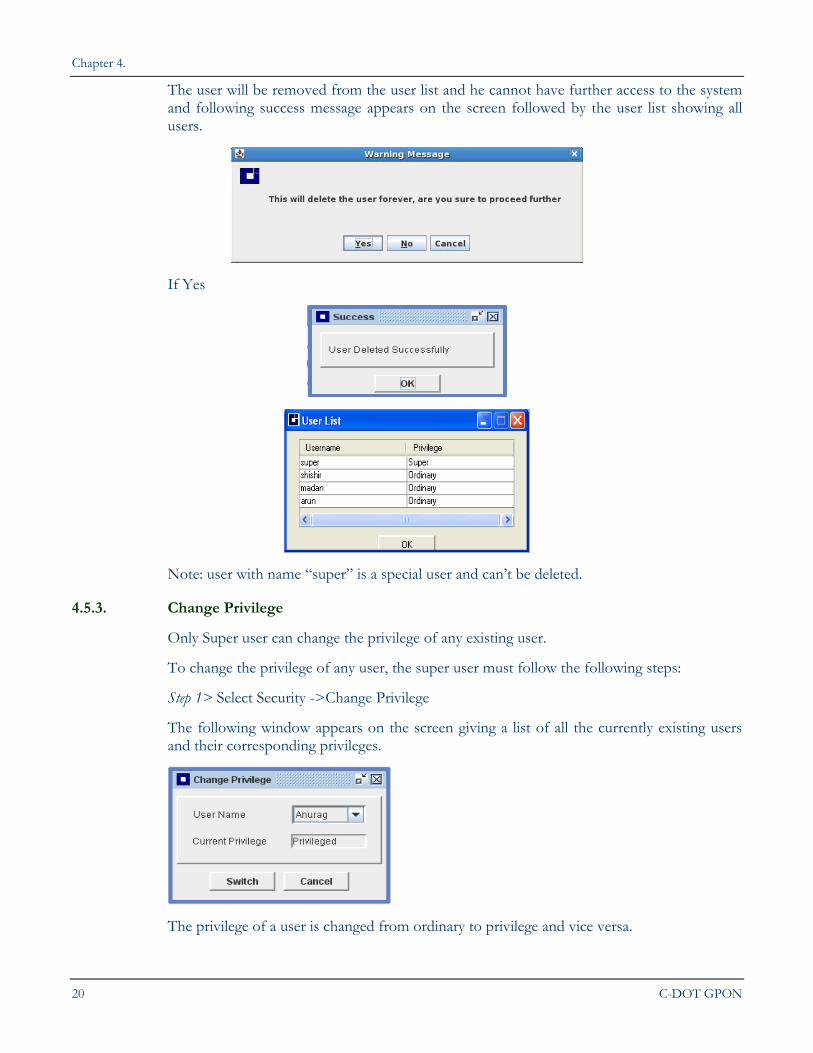
The user will be removed from the user list and he cannot have further access to the system and following success message appears on the screen followed by the user list showing all users.
If Yes
Note: user with name “super” is a special user and can’t be deleted.
4.5.3. Change Privilege
Only Super user can change the privilege of any existing user.
To change the privilege of any user, the super user must follow the following steps:
Step 1> Select Security ->Change Privilege
The following window appears on the screen giving a list of all the currently existing users and their corresponding privileges.
The privilege of a user is changed from ordinary to privilege and vice versa.
COMMISSIONING A GPON LCT NETWORK ELEMENT
LCT USER MANUAL 21
Step 2> Select the name of the user whose privilege is to be changed and click Switch. Following success message appears on the screen followed by the user list showing all users.
For example: The user “Anurag” with privilege as “ordinary” has been selected in this case. Thus his privilege will be changed to “privileged”.
4.5.4. Change Password
GPON LCT Software provides the facility to change the password of any user.
Note: Super user can change the password of any existing user while ordinary and privileged users can change their own passwords only.
The following steps should be followed to change the password of a user
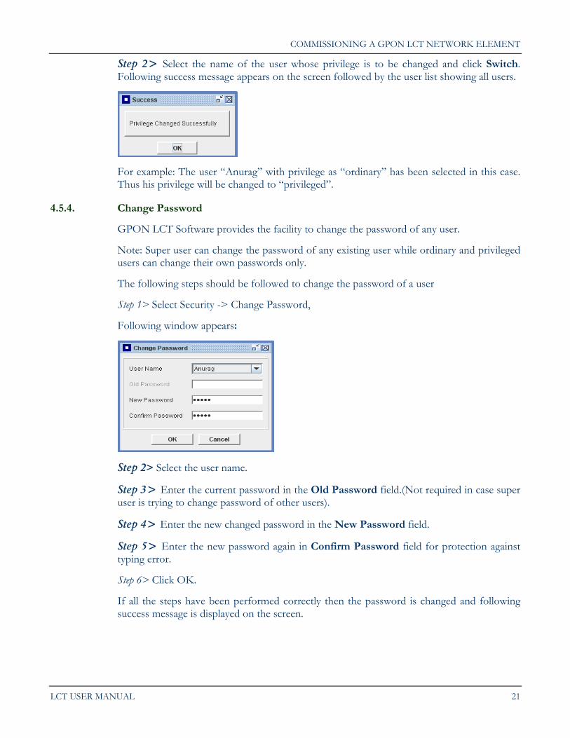
Step 1> Select Security -> Change Password,
Following window appears:
Step 2> Select the user name.
Step 3> Enter the current password in the Old Password field.(Not required in case super user is trying to change password of other users).
Step 4> Enter the new changed password in the New Password field.
Step 5> Enter the new password again in Confirm Password field for protection against typing error.
Step 6> Click OK.
If all the steps have been performed correctly then the password is changed and following success message is displayed on the screen.
Chapter 4.
22 C-DOT GPON
4.5.5. List of Users
GPON LCT Software provides the facility to view all the registered users on the system. Only these users can have an access to the system.
To view the list of registered users, the following steps should be followed:
Step 1> Select Security > List of User
The following screen appears which gives a list of all the users on the system.
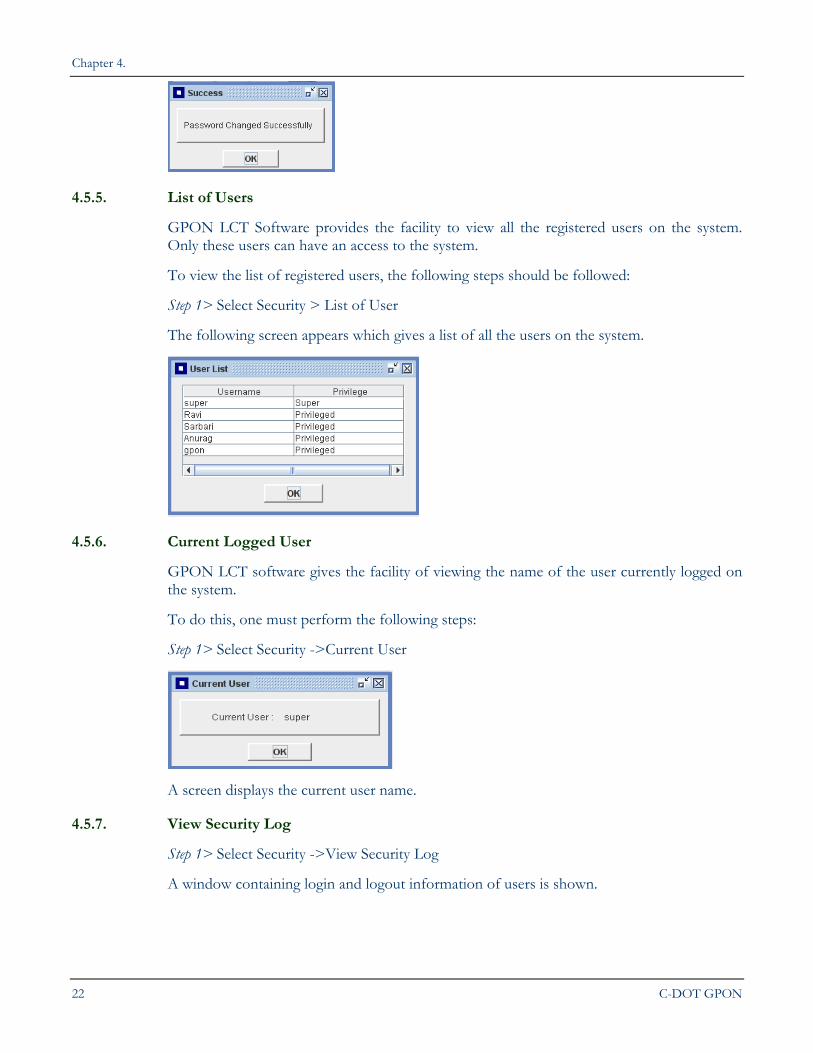
4.5.6. Current Logged User
GPON LCT software gives the facility of viewing the name of the user currently logged on the system.
To do this, one must perform the following steps:
Step 1> Select Security ->Current User
A screen displays the current user name.
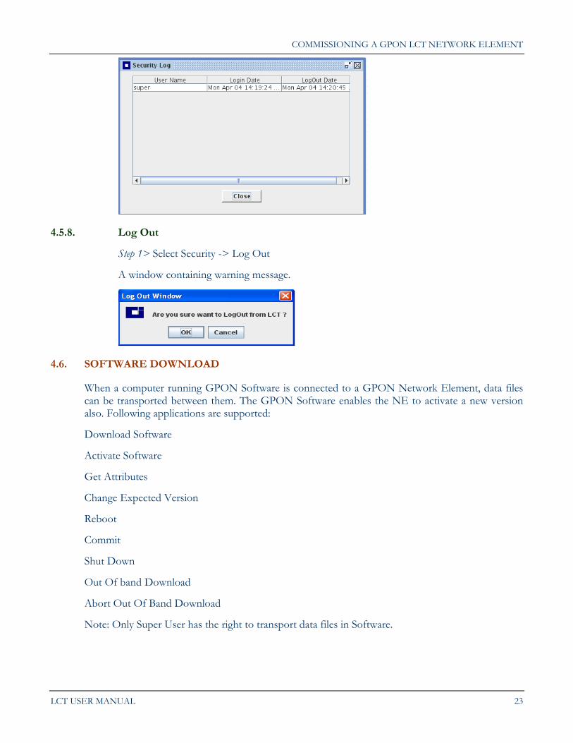
4.5.7. View Security Log
Step 1> Select Security ->View Security Log
A window containing login and logout information of users is shown.
COMMISSIONING A GPON LCT NETWORK ELEMENT
LCT USER MANUAL 23
4.5.8. Log Out
Step 1> Select Security -> Log Out
A window containing warning message.
4.6. SOFTWARE DOWNLOAD
When a computer running GPON Software is connected to a GPON Network Element, data files can be transported between them. The GPON Software enables the NE to activate a new version also. Following applications are supported:
Download Software
Activate Software
Get Attributes
Change Expected Version
Reboot
Commit
Shut Down
Out Of band Download
Abort Out Of Band Download
Note: Only Super User has the right to transport data files in Software.
Chapter 4.
24 C-DOT GPON
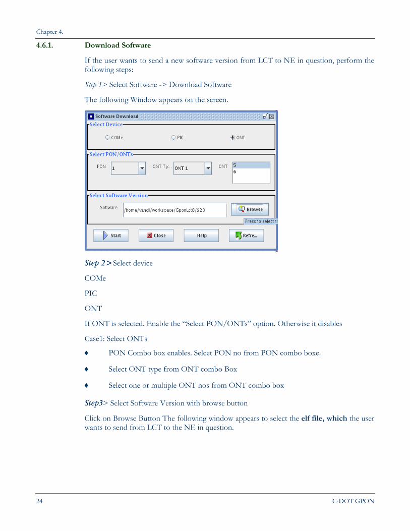
4.6.1. Download Software
If the user wants to send a new software version from LCT to NE in question, perform the following steps:
Step 1> Select Software -> Download Software
The following Window appears on the screen.
Step 2>Select device
COMe
PIC
ONT
If ONT is selected. Enable the “Select PON/ONTs” option. Otherwise it disables
Case1: Select ONTs
PON Combo box enables. Selcet PON no from PON combo boxe.
Select ONT type from ONT combo Box
Select one or multiple ONT nos from ONT combo box
Step3> Select Software Version with browse button
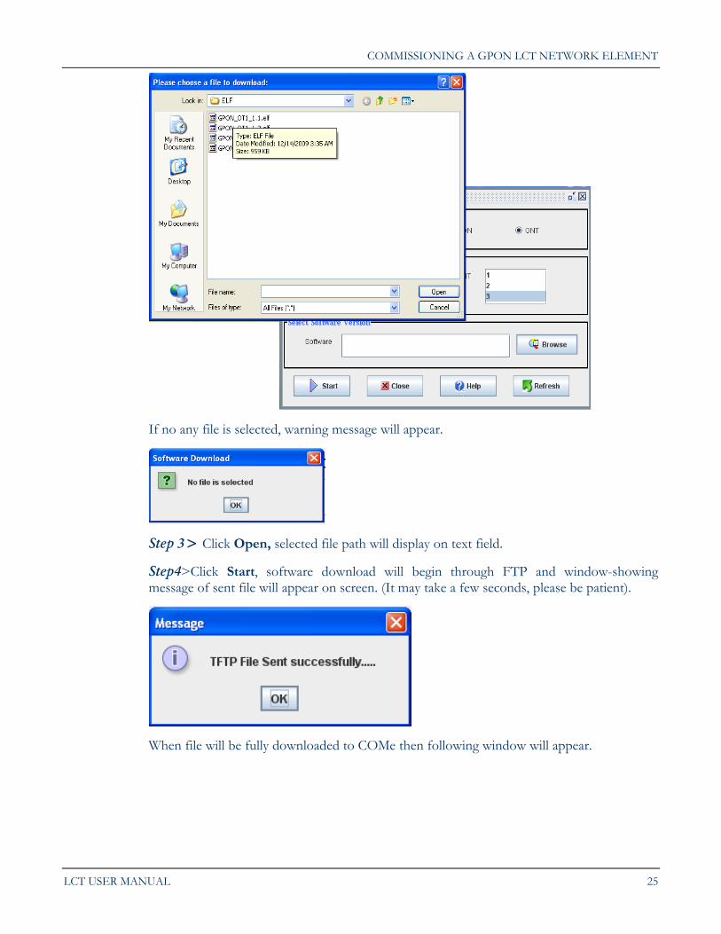
Click on Browse Button The following window appears to select the elf file, which the user wants to send from LCT to the NE in question.
COMMISSIONING A GPON LCT NETWORK ELEMENT
LCT USER MANUAL 25
If no any file is selected, warning message will appear.
Step 3> Click Open, selected file path will display on text field.
Step4>Click Start, software download will begin through FTP and window-showing message of sent file will appear on screen. (It may take a few seconds, please be patient).
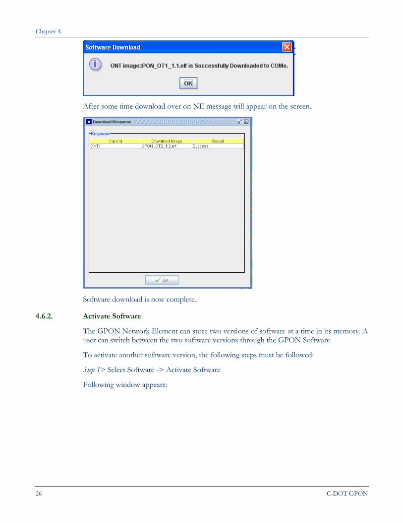
When file will be fully downloaded to COMe then following window will appear.
Chapter 4.
26 C-DOT GPON
After some time download over on NE message will appear on the screen.
Software download is now complete.
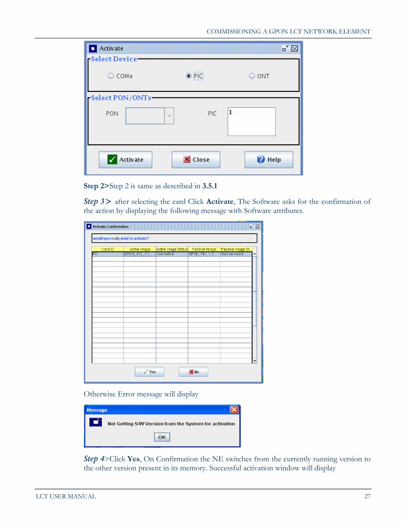
4.6.2. Activate Software
The GPON Network Element can store two versions of software at a time in its memory. A user can switch between the two software versions through the GPON Software.
To activate another software version, the following steps must be followed:
Step 1> Select Software -> Activate Software
Following window appears:
COMMISSIONING A GPON LCT NETWORK ELEMENT
LCT USER MANUAL 27
Step 2>Step 2 is same as described in 3.5.1
Step 3> after selecting the card Click Activate, The Software asks for the confirmation of the action by displaying the following message with Software attributes.
Otherwise Error message will display
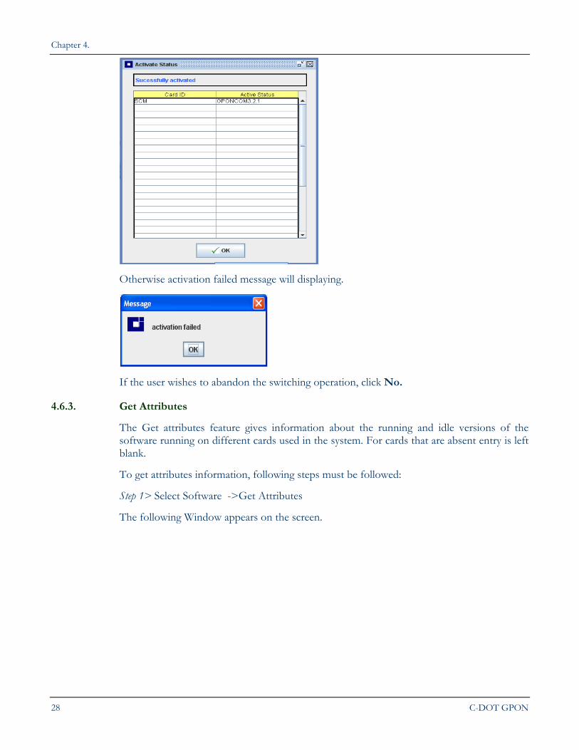
Step 4>Click Yes, On Confirmation the NE switches from the currently running version to the other version present in its memory. Successful activation window will display
Chapter 4.
28 C-DOT GPON
Otherwise activation failed message will displaying.
If the user wishes to abandon the switching operation, click No.
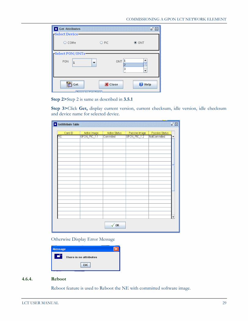
4.6.3. Get Attributes
The Get attributes feature gives information about the running and idle versions of the software running on different cards used in the system. For cards that are absent entry is left blank.
To get attributes information, following steps must be followed:
Step 1> Select Software ->Get Attributes
The following Window appears on the screen.
COMMISSIONING A GPON LCT NETWORK ELEMENT
LCT USER MANUAL 29
Step 2>Step 2 is same as described in 3.5.1
Step 3>Click Get, display current version, current checksum, idle version, idle checksum and device name for selected device.
Otherwise Display Error Message
4.6.4. Reboot
Reboot feature is used to Reboot the NE with committed software image.
Chapter 4.
30 C-DOT GPON
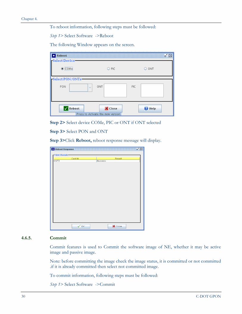
To reboot information, following steps must be followed:
Step 1> Select Software ->Reboot
The following Window appears on the screen.
Step 2> Select device COMe, PIC or ONT if ONT selected
Step 3> Select PON and ONT
Step 3>Click Reboot, reboot response message will display.
4.6.5. Commit
Commit features is used to Commit the software image of NE, whether it may be active image and passive image.
Note: before committing the image check the image status, it is committed or not committed .if it is already committed then select not committed image.
To commit information, following steps must be followed:
Step 1> Select Software ->Commit
COMMISSIONING A GPON LCT NETWORK ELEMENT
LCT USER MANUAL 31
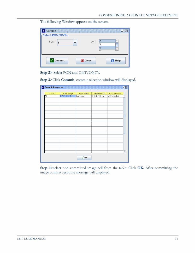
The following Window appears on the screen.
Step 2> Select PON and ONT/ONT's.
Step 3>Click Commit, commit selection window will displayed.
Step 4>select non committed image cell from the table. Click OK. After committing the image commit response message will displayed.
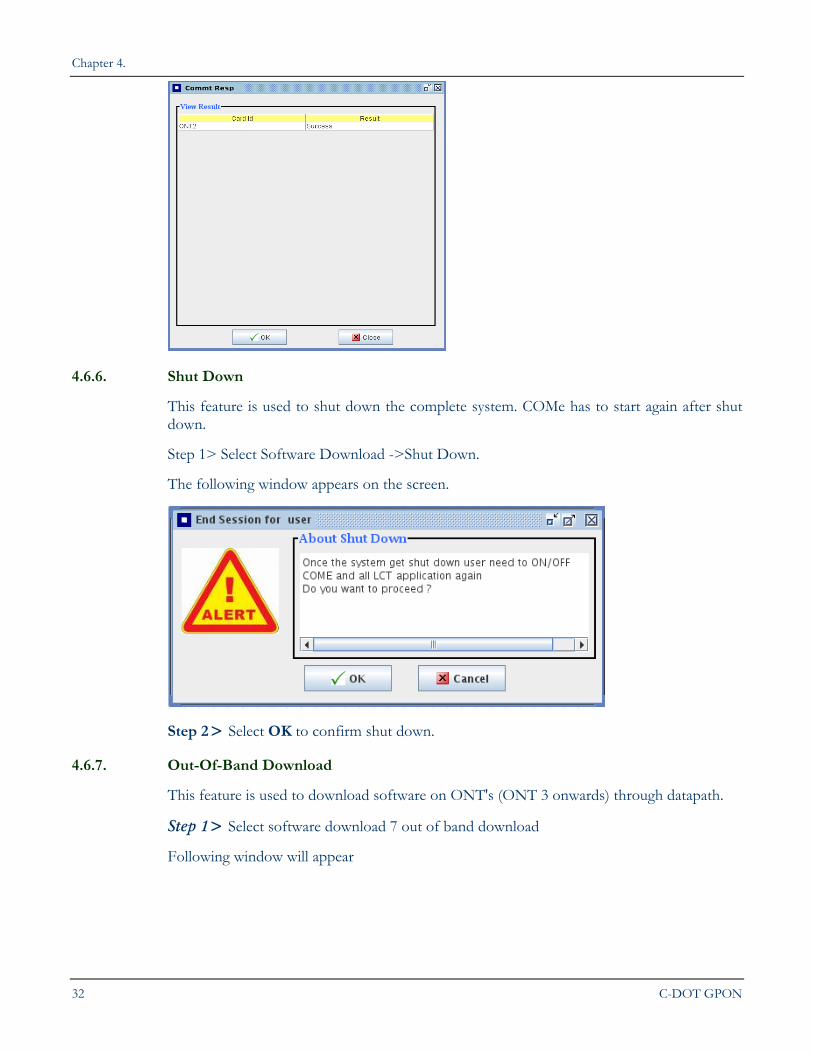
Chapter 4.
32 C-DOT GPON
4.6.6. Shut Down
This feature is used to shut down the complete system. COMe has to start again after shut down.
Step 1> Select Software Download ->Shut Down.
The following window appears on the screen.
Step 2> Select OK to confirm shut down.
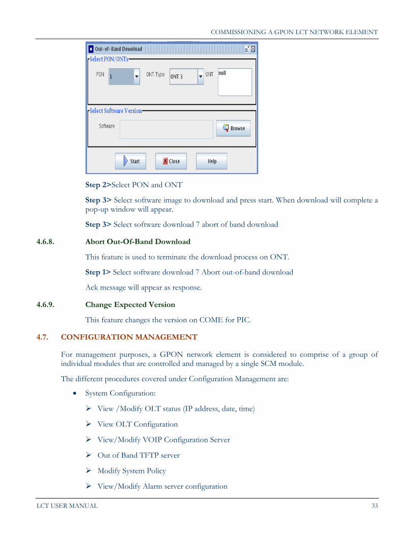
4.6.7. Out-Of-Band Download
This feature is used to download software on ONT's (ONT 3 onwards) through datapath.
Step 1> Select software download 7 out of band download
Following window will appear
COMMISSIONING A GPON LCT NETWORK ELEMENT
LCT USER MANUAL 33
Step 2>Select PON and ONT
Step 3> Select software image to download and press start. When download will complete a pop-up window will appear.
Step 3> Select software download 7 abort of band download
4.6.8. Abort Out-Of-Band Download
This feature is used to terminate the download process on ONT.
Step 1> Select software download 7 Abort out-of-band download
Ack message will appear as response.
4.6.9. Change Expected Version
This feature changes the version on COME for PIC.
4.7. CONFIGURATION MANAGEMENT
For management purposes, a GPON network element is considered to comprise of a group of individual modules that are controlled and managed by a single SCM module.
The different procedures covered under Configuration Management are:
System Configuration:
View /Modify OLT status (IP address, date, time)
View OLT Configuration
View/Modify VOIP Configuration Server
Out of Band TFTP server
Modify System Policy
View/Modify Alarm server configuration
Chapter 4.
34 C-DOT GPON
View/Modify Log Server Configuration
LoopBack Management
ONT Configuration:
Register ONT
View ONT Status
ONT Power Pack Details
Change ONT State
View ONT Configuration
Modify ONT Admin State
View Modify Optical Threshold
View Modify UNI/ANI
DHCP Enable Disable
View ONT VOIP IP Info.
AES Enable/Disable
Mac address Limiting
ONT Flow Control
View ONT Distance
PON Configuration:
View PON Configuration
PON Name
PON Physical Reach
Activate/Deactivate
PIC Configuration:
View PIC Configuration
View PIC Type
Protection /APS
FEC Enable Disable
SCM SwitchOver
View SNI Port Map
COMMISSIONING A GPON LCT NETWORK ELEMENT
LCT USER MANUAL 35
Get Set SNI Protection
View SNI SFP info of ONT14
SNI Sfp Info
Get SNI Sfp Info
Get/Set SNI Sfp Type
Get/Set SNI Transmitter state
Get/Set SNI ALS
4.7.1. System Configuration
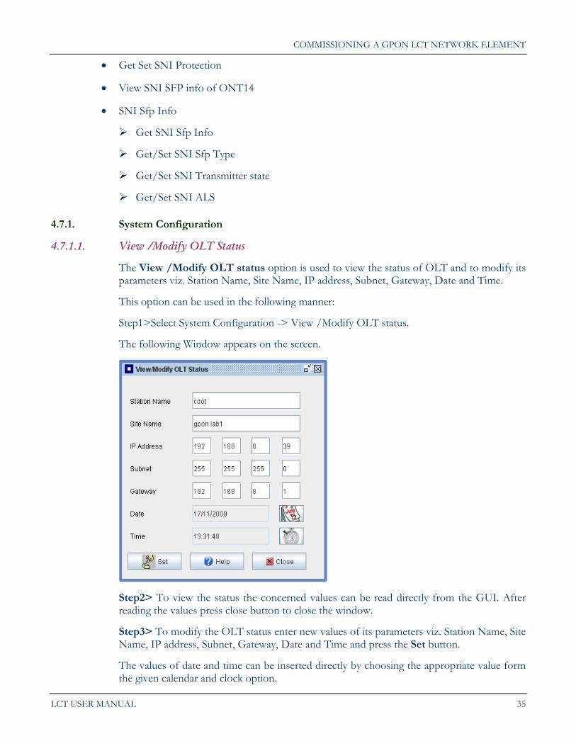
4.7.1.1. View /Modify OLT Status
The View /Modify OLT status option is used to view the status of OLT and to modify its parameters viz. Station Name, Site Name, IP address, Subnet, Gateway, Date and Time.
This option can be used in the following manner:
Step1>Select System Configuration -> View /Modify OLT status.
The following Window appears on the screen.
Step2> To view the status the concerned values can be read directly from the GUI. After reading the values press close button to close the window.
Step3> To modify the OLT status enter new values of its parameters viz. Station Name, Site Name, IP address, Subnet, Gateway, Date and Time and press the Set button.
The values of date and time can be inserted directly by choosing the appropriate value form the given calendar and clock option.
Chapter 4.
36 C-DOT GPON
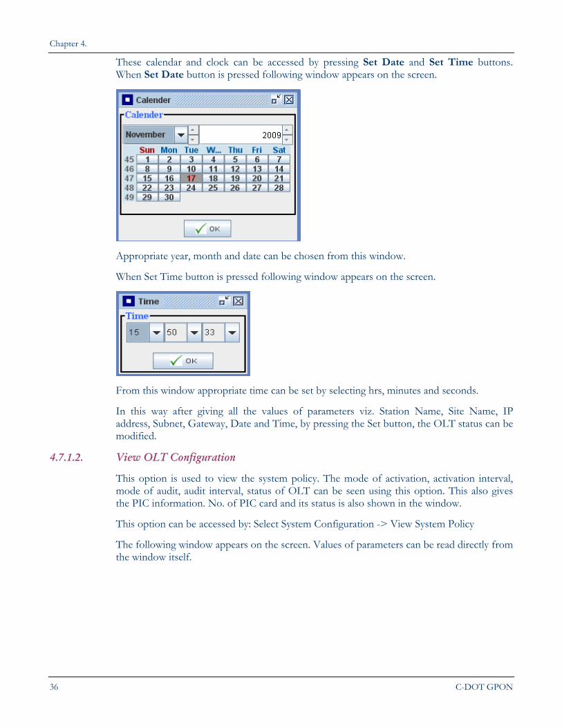
These calendar and clock can be accessed by pressing Set Date and Set Time buttons. When Set Date button is pressed following window appears on the screen.
Appropriate year, month and date can be chosen from this window.
When Set Time button is pressed following window appears on the screen.
From this window appropriate time can be set by selecting hrs, minutes and seconds.
In this way after giving all the values of parameters viz. Station Name, Site Name, IP address, Subnet, Gateway, Date and Time, by pressing the Set button, the OLT status can be modified.
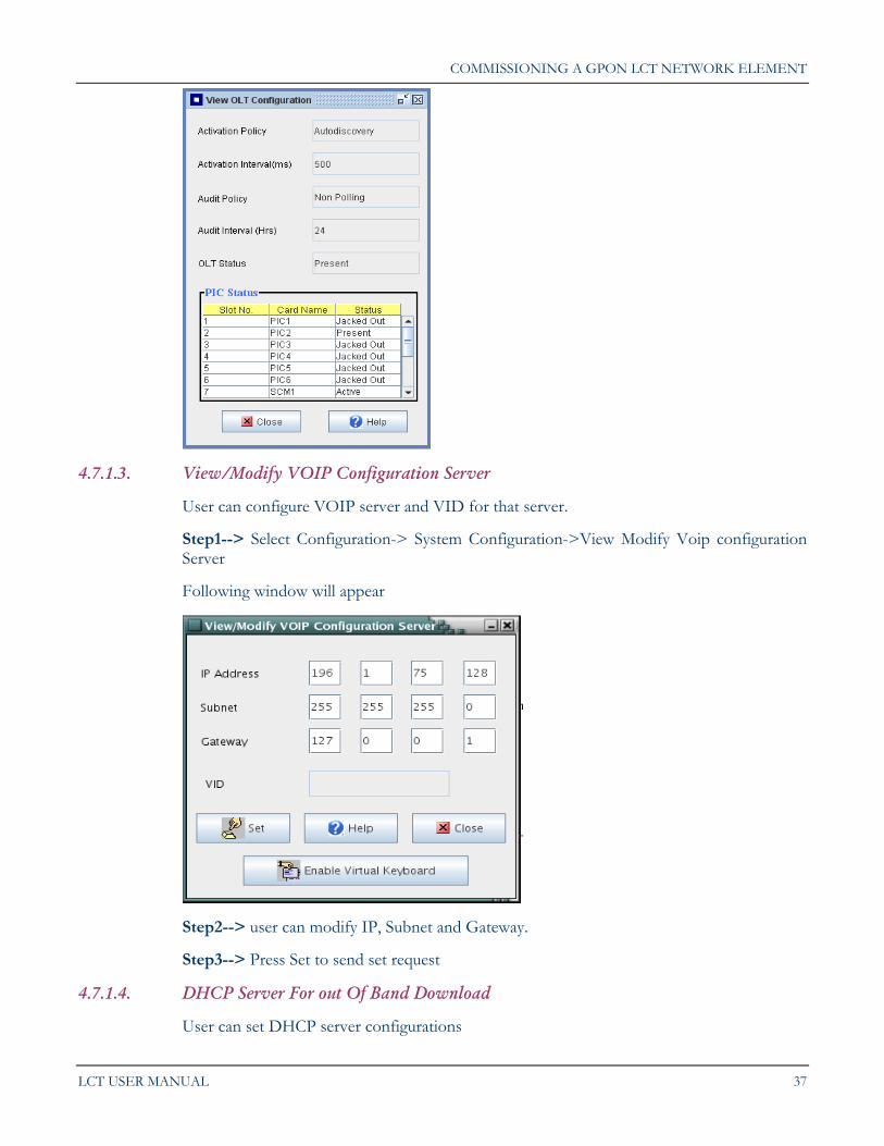
4.7.1.2. View OLT Configuration
This option is used to view the system policy. The mode of activation, activation interval, mode of audit, audit interval, status of OLT can be seen using this option. This also gives the PIC information. No. of PIC card and its status is also shown in the window.
This option can be accessed by: Select System Configuration -> View System Policy
The following window appears on the screen. Values of parameters can be read directly from the window itself.
COMMISSIONING A GPON LCT NETWORK ELEMENT
LCT USER MANUAL 37
4.7.1.3. View/Modify VOIP Configuration Server
User can configure VOIP server and VID for that server.
Step1--> Select Configuration-> System Configuration->View Modify Voip configuration Server
Following window will appear
Step2--> user can modify IP, Subnet and Gateway.
Step3--> Press Set to send set request
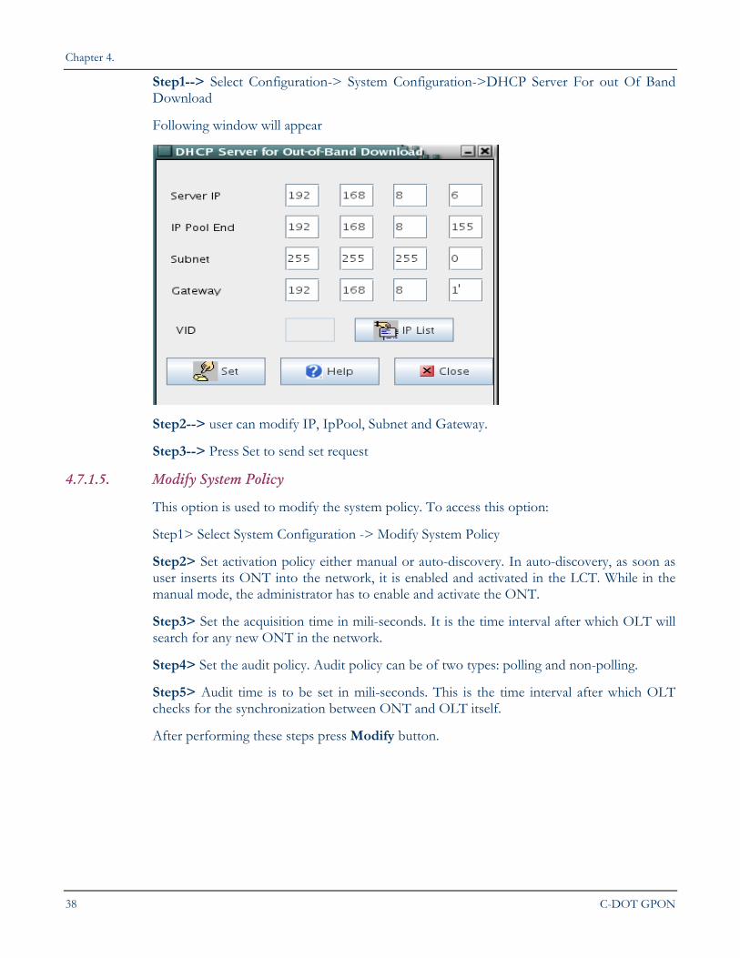
4.7.1.4. DHCP Server For out Of Band Download
User can set DHCP server configurations
Chapter 4.
38 C-DOT GPON
Step1--> Select Configuration-> System Configuration->DHCP Server For out Of Band Download
Following window will appear
Step2--> user can modify IP, IpPool, Subnet and Gateway.
Step3--> Press Set to send set request
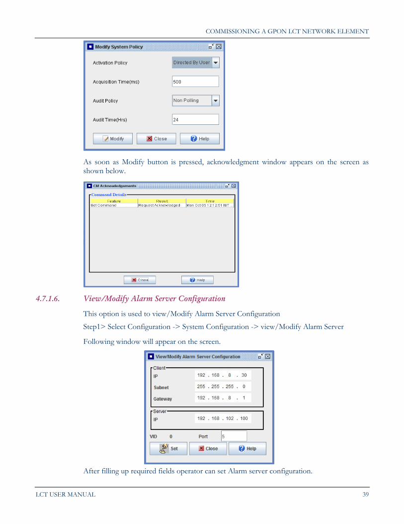
4.7.1.5. Modify System Policy
This option is used to modify the system policy. To access this option:
Step1> Select System Configuration -> Modify System Policy
Step2> Set activation policy either manual or auto-discovery. In auto-discovery, as soon as user inserts its ONT into the network, it is enabled and activated in the LCT. While in the manual mode, the administrator has to enable and activate the ONT.
Step3> Set the acquisition time in mili-seconds. It is the time interval after which OLT will search for any new ONT in the network.
Step4> Set the audit policy. Audit policy can be of two types: polling and non-polling.
Step5> Audit time is to be set in mili-seconds. This is the time interval after which OLT checks for the synchronization between ONT and OLT itself.
After performing these steps press Modify button.
COMMISSIONING A GPON LCT NETWORK ELEMENT
LCT USER MANUAL 39
As soon as Modify button is pressed, acknowledgment window appears on the screen as shown below.
4.7.1.6. View/Modify Alarm Server Configuration
This option is used to view/Modify Alarm Server Configuration
Step1> Select Configuration -> System Configuration -> view/Modify Alarm Server
Following window will appear on the screen.
After filling up required fields operator can set Alarm server configuration.
Chapter 4.
40 C-DOT GPON
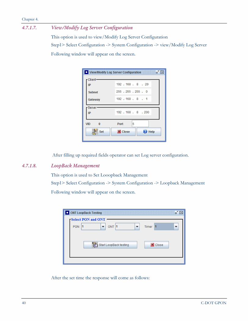
4.7.1.7. View/Modify Log Server Configuration
This option is used to view/Modify Log Server Configuration
Step1> Select Configuration -> System Configuration -> view/Modify Log Server
Following window will appear on the screen.
After filling up required fields operator can set Log server configuration.
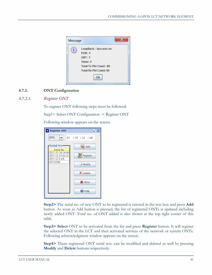
4.7.1.8. LoopBack Management
This option is used to Set Looopback Management
Step1> Select Configuration -> System Configuration -> Loopback Management
Following window will appear on the screen.
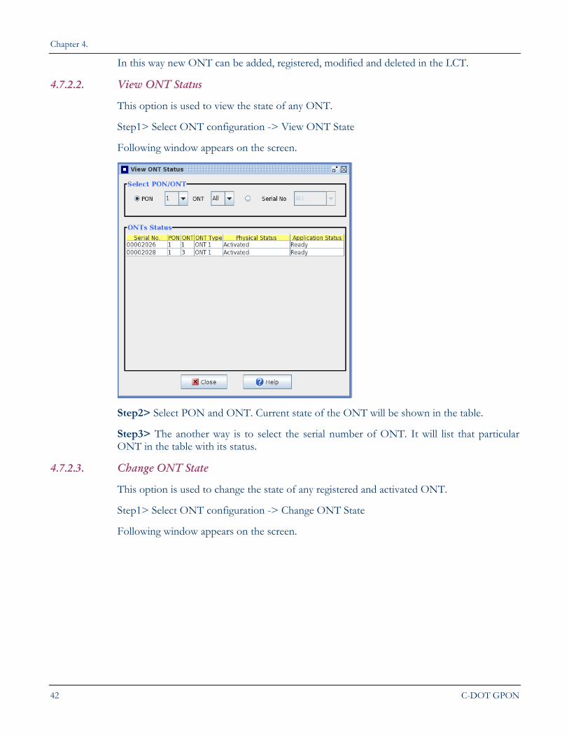
After the set time the response will come as follows:
COMMISSIONING A GPON LCT NETWORK ELEMENT
LCT USER MANUAL 41
4.7.2. ONT Configuration
4.7.2.1. Register ONT
To register ONT following steps must be followed:
Step1> Select ONT Configuration -> Register ONT
Following window appears on the screen.
Step2> The serial no. of new ONT to be registered is entered in the text box and press Add button. As soon as Add button is pressed, the list of registered ONTs is updated including newly added ONT. Total no. of ONT added is also shown at the top right corner of this table.
Step3> Select ONT to be activated from the list and press Register button. It will register the selected ONT in the LCT and then activated services of the network or system ONTs. Following acknowledgment window appears on the screen.
Step4> These registered ONT serial nos. can be modified and deleted as well by pressing Modify and Delete buttons respectively.
Chapter 4.
42 C-DOT GPON
In this way new ONT can be added, registered, modified and deleted in the LCT.
4.7.2.2. View ONT Status
This option is used to view the state of any ONT.
Step1> Select ONT configuration -> View ONT State
Following window appears on the screen.
Step2> Select PON and ONT. Current state of the ONT will be shown in the table.
Step3> The another way is to select the serial number of ONT. It will list that particular ONT in the table with its status.
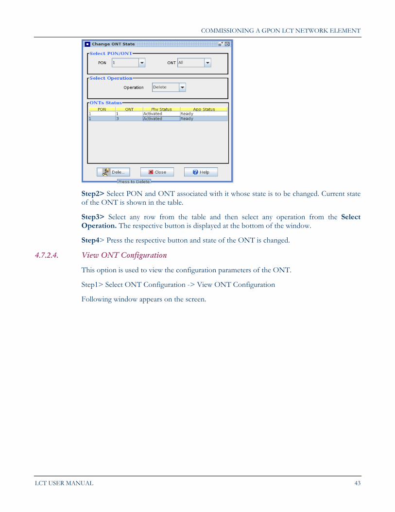
4.7.2.3. Change ONT State
This option is used to change the state of any registered and activated ONT.
Step1> Select ONT configuration -> Change ONT State
Following window appears on the screen.
COMMISSIONING A GPON LCT NETWORK ELEMENT
LCT USER MANUAL 43
Step2> Select PON and ONT associated with it whose state is to be changed. Current state of the ONT is shown in the table.
Step3> Select any row from the table and then select any operation from the Select Operation. The respective button is displayed at the bottom of the window.
Step4> Press the respective button and state of the ONT is changed.
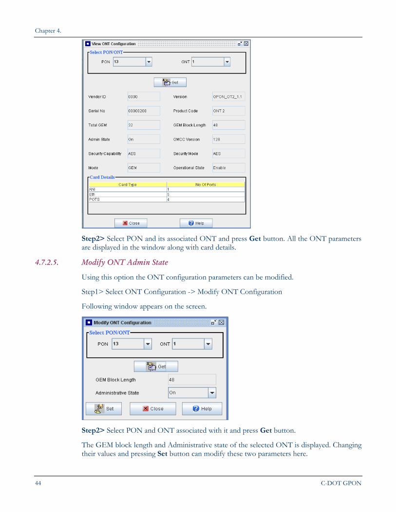
4.7.2.4. View ONT Configuration
This option is used to view the configuration parameters of the ONT.
Step1> Select ONT Configuration -> View ONT Configuration
Following window appears on the screen.
Chapter 4.
44 C-DOT GPON
Step2> Select PON and its associated ONT and press Get button. All the ONT parameters are displayed in the window along with card details.
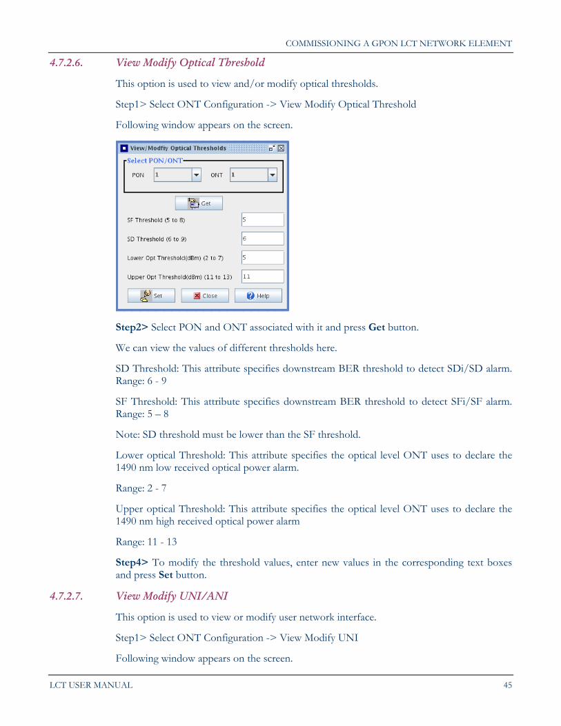
4.7.2.5. Modify ONT Admin State
Using this option the ONT configuration parameters can be modified.
Step1> Select ONT Configuration -> Modify ONT Configuration
Following window appears on the screen.
Step2> Select PON and ONT associated with it and press Get button.
The GEM block length and Administrative state of the selected ONT is displayed. Changing their values and pressing Set button can modify these two parameters here.
COMMISSIONING A GPON LCT NETWORK ELEMENT
LCT USER MANUAL 45
4.7.2.6. View Modify Optical Threshold
This option is used to view and/or modify optical thresholds.
Step1> Select ONT Configuration -> View Modify Optical Threshold
Following window appears on the screen.
Step2> Select PON and ONT associated with it and press Get button.
We can view the values of different thresholds here.
SD Threshold: This attribute specifies downstream BER threshold to detect SDi/SD alarm. Range: 6 - 9
SF Threshold: This attribute specifies downstream BER threshold to detect SFi/SF alarm. Range: 5 – 8
Note: SD threshold must be lower than the SF threshold.
Lower optical Threshold: This attribute specifies the optical level ONT uses to declare the 1490 nm low received optical power alarm.
Range: 2 - 7
Upper optical Threshold: This attribute specifies the optical level ONT uses to declare the 1490 nm high received optical power alarm
Range: 11 - 13
Step4> To modify the threshold values, enter new values in the corresponding text boxes and press Set button.
4.7.2.7. View Modify UNI/ANI
This option is used to view or modify user network interface.
Step1> Select ONT Configuration -> View Modify UNI
Following window appears on the screen.

Chapter 4.
46 C-DOT GPON
Step2> To view UNI select PON and ONT associated with it and press Get button. It shows the ONT status in the table in the same window.
Step3> To modify the card status, click on the modify Card radio button. Following window will appear on the screen.
Selecting proper card and action (on/off) and pressing Set button will change the state of the Card.
Step4> To modify the port status, click on the modify Card radio button. Following window will appear on the screen.
COMMISSIONING A GPON LCT NETWORK ELEMENT
LCT USER MANUAL 47
Select proper card whose status is to be modified, its all the ports are displayed in a table in the same window. The administrative state of each card is also displayed against each card. This state can be selected (on/off). On pressing Set button the state of the card is changed. The bandwidth can also be selected for each of the port individually as per requirement.
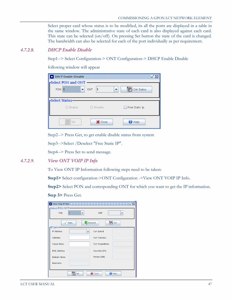
4.7.2.8. DHCP Enable Disable
Step1--> Select Configuration-> ONT Configuration-> DHCP Enable Disable
following window will appear
Step2--> Press Get, to get enable disable status from system
Step3-->Select /Deselect "Free Static IP".
Step4--> Press Set to send message.
4.7.2.9. View ONT VOIP IP Info
To View ONT IP Information following steps need to be taken:
Step1> Select configuration->ONT Configuration ->View ONT VOIP IP Info.
Step2> Select PON and corresponding ONT for which you want to get the IP information.
Step 3> Press Get.
Chapter 4.
48 C-DOT GPON
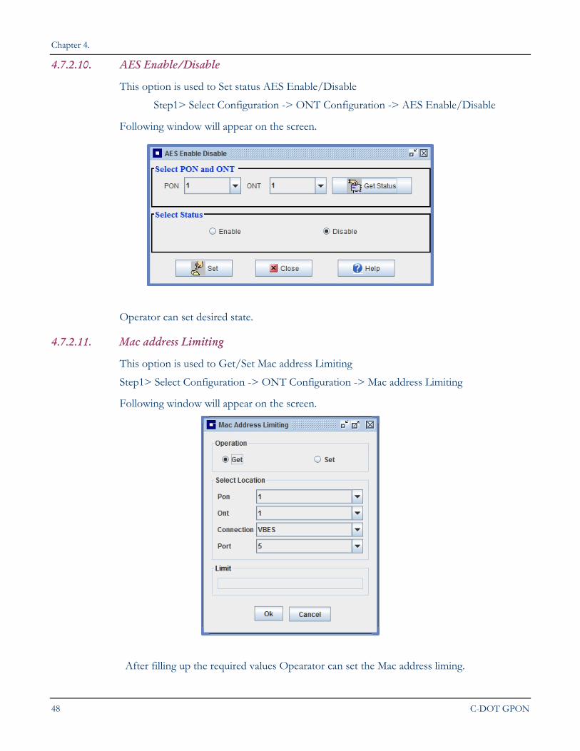
4.7.2.10. AES Enable/Disable
This option is used to Set status AES Enable/Disable
Step1> Select Configuration -> ONT Configuration -> AES Enable/Disable
Following window will appear on the screen.
Operator can set desired state.
4.7.2.11. Mac address Limiting
This option is used to Get/Set Mac address Limiting
Step1> Select Configuration -> ONT Configuration -> Mac address Limiting
Following window will appear on the screen.
After filling up the required values Opearator can set the Mac address liming.
COMMISSIONING A GPON LCT NETWORK ELEMENT
LCT USER MANUAL 49
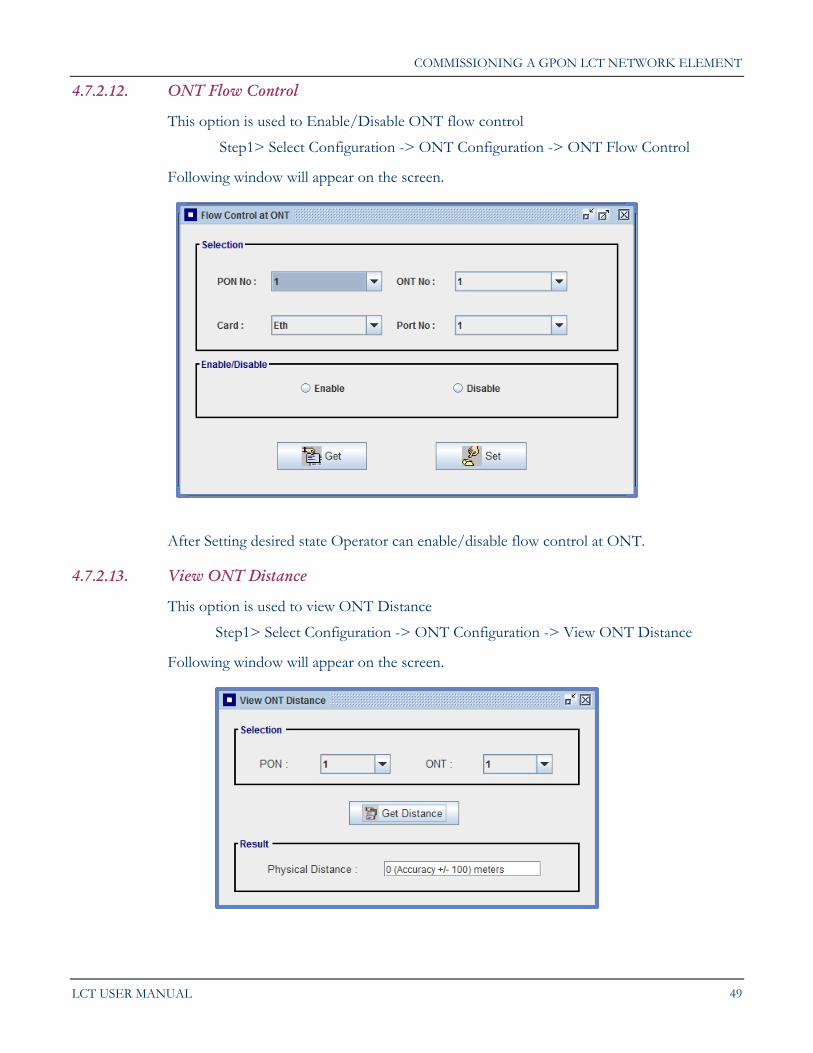
4.7.2.12. ONT Flow Control
This option is used to Enable/Disable ONT flow control
Step1> Select Configuration -> ONT Configuration -> ONT Flow Control
Following window will appear on the screen.
After Setting desired state Operator can enable/disable flow control at ONT.
4.7.2.13. View ONT Distance
This option is used to view ONT Distance
Step1> Select Configuration -> ONT Configuration -> View ONT Distance
Following window will appear on the screen.
Chapter 4.
50 C-DOT GPON
4.7.3. PON Configuration
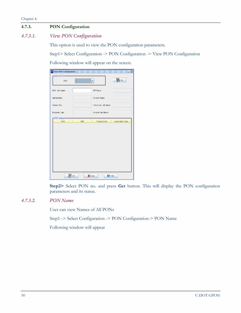
4.7.3.1. View PON Configuration
This option is used to view the PON configuration parameters.
Step1> Select Configuration -> PON Configuration -> View PON Configuration
Following window will appear on the screen.
Step2> Select PON no. and press Get button. This will display the PON configuration parameters and its status.
4.7.3.2. PON Name
User can view Names of All PONs
Step1--> Select Configuration -> PON Configuration-> PON Name
Following window will appear
COMMISSIONING A GPON LCT NETWORK ELEMENT
LCT USER MANUAL 51
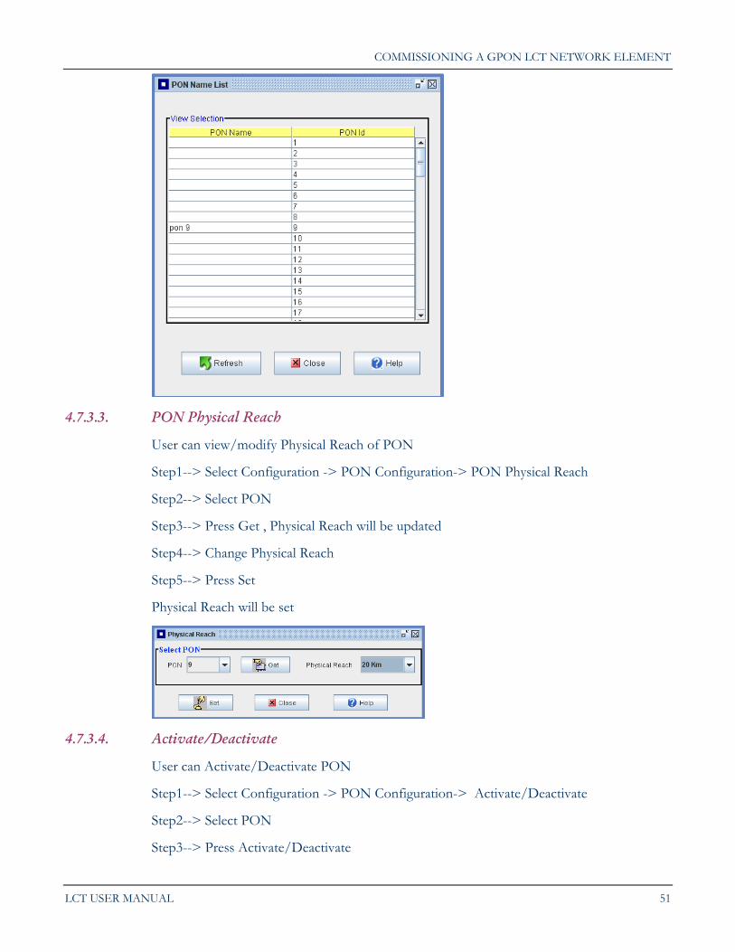
4.7.3.3. PON Physical Reach
User can view/modify Physical Reach of PON
Step1--> Select Configuration -> PON Configuration-> PON Physical Reach
Step2--> Select PON
Step3--> Press Get , Physical Reach will be updated
Step4--> Change Physical Reach
Step5--> Press Set
Physical Reach will be set
4.7.3.4. Activate/Deactivate
User can Activate/Deactivate PON
Step1--> Select Configuration -> PON Configuration-> Activate/Deactivate
Step2--> Select PON
Step3--> Press Activate/Deactivate
Chapter 4.
52 C-DOT GPON
4.7.4. PIC Configuration
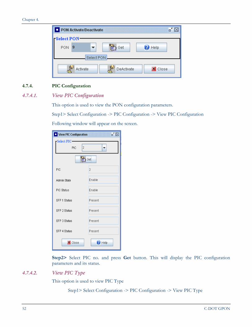
4.7.4.1. View PIC Configuration
This option is used to view the PON configuration parameters.
Step1> Select Configuration -> PIC Configuration -> View PIC Configuration
Following window will appear on the screen.
Step2> Select PIC no. and press Get button. This will display the PIC configuration parameters and its status.
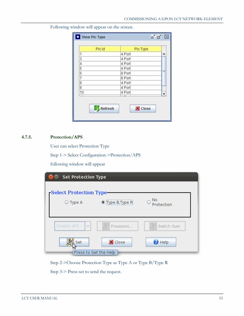
4.7.4.2. View PIC Type
This option is used to view PIC Type
Step1> Select Configuration -> PIC Configuration -> View PIC Type
COMMISSIONING A GPON LCT NETWORK ELEMENT
LCT USER MANUAL 53
Following window will appear on the screen.
4.7.5. Protection/APS
User can select Protection Type
Step 1-> Select Configuration->Protection/APS
following window will appear
Step 2->Choose Protection Type as Type A or Type B/Type R
Step 3-> Press set to send the request.
Chapter 4.
54 C-DOT GPON
User has to select "No Protection" to change the protection type from A to B /R or vice versa.
Provisioning options are available with protection type B/type R.
Switchover options are only available with protection type B.
APS enable and disable options are only available with protection type A.
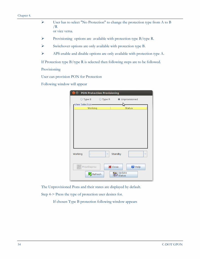
If Protection type B/type R is selected then following steps are to be followed.
Provisioning
User can provision PON for Protection
Following window will appear
The Unprovisioned Pons and their states are displayed by default.
Step 4-> Press the type of protection user desires for.
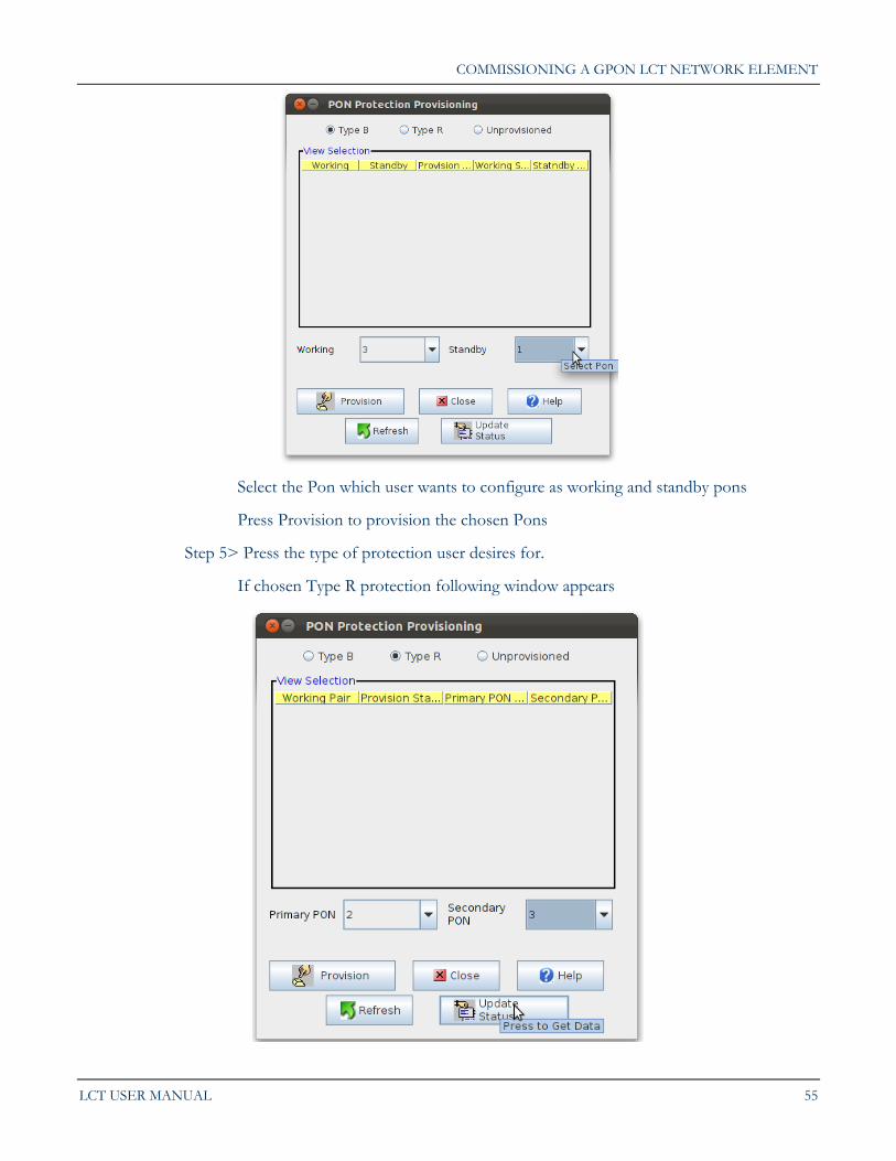
If chosen Type B protection following window appears
COMMISSIONING A GPON LCT NETWORK ELEMENT
LCT USER MANUAL 55
Select the Pon which user wants to configure as working and standby pons
Press Provision to provision the chosen Pons
Step 5> Press the type of protection user desires for.
If chosen Type R protection following window appears
Chapter 4.
56 C-DOT GPON
Select the Pon which user wants to configure as Primary and Secondary pons
Press Provision to provision the chosen Pons
Step 6-> Press Update Status to update the status of pons after provisioning/deprovisioning
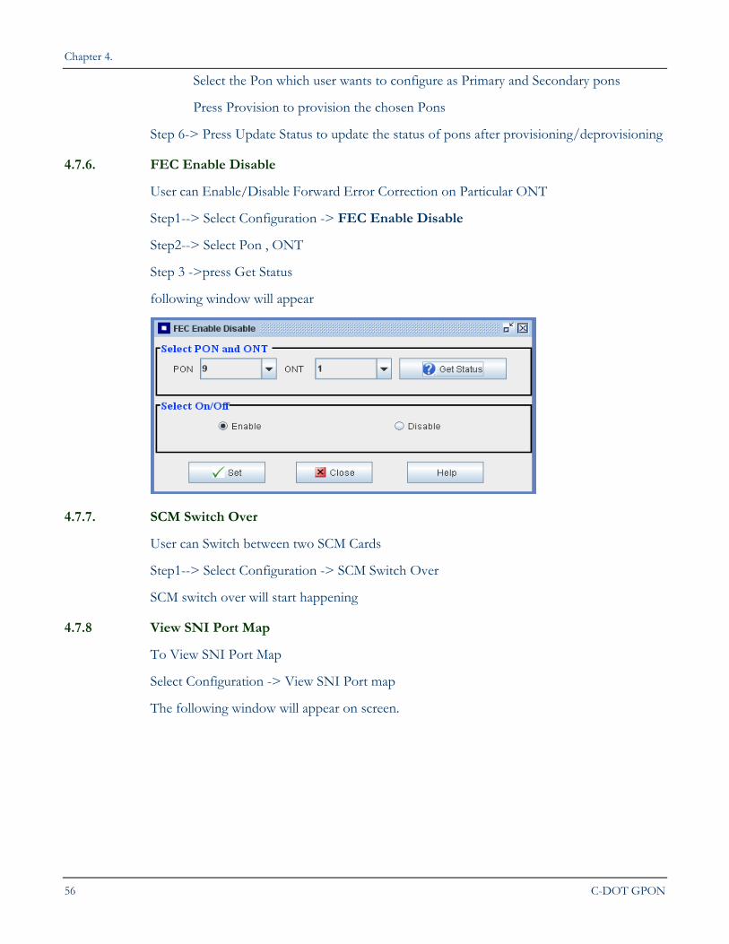
4.7.6. FEC Enable Disable
User can Enable/Disable Forward Error Correction on Particular ONT
Step1--> Select Configuration -> FEC Enable Disable
Step2--> Select Pon , ONT
Step 3 ->press Get Status
following window will appear
4.7.7. SCM Switch Over
User can Switch between two SCM Cards
Step1--> Select Configuration -> SCM Switch Over
SCM switch over will start happening
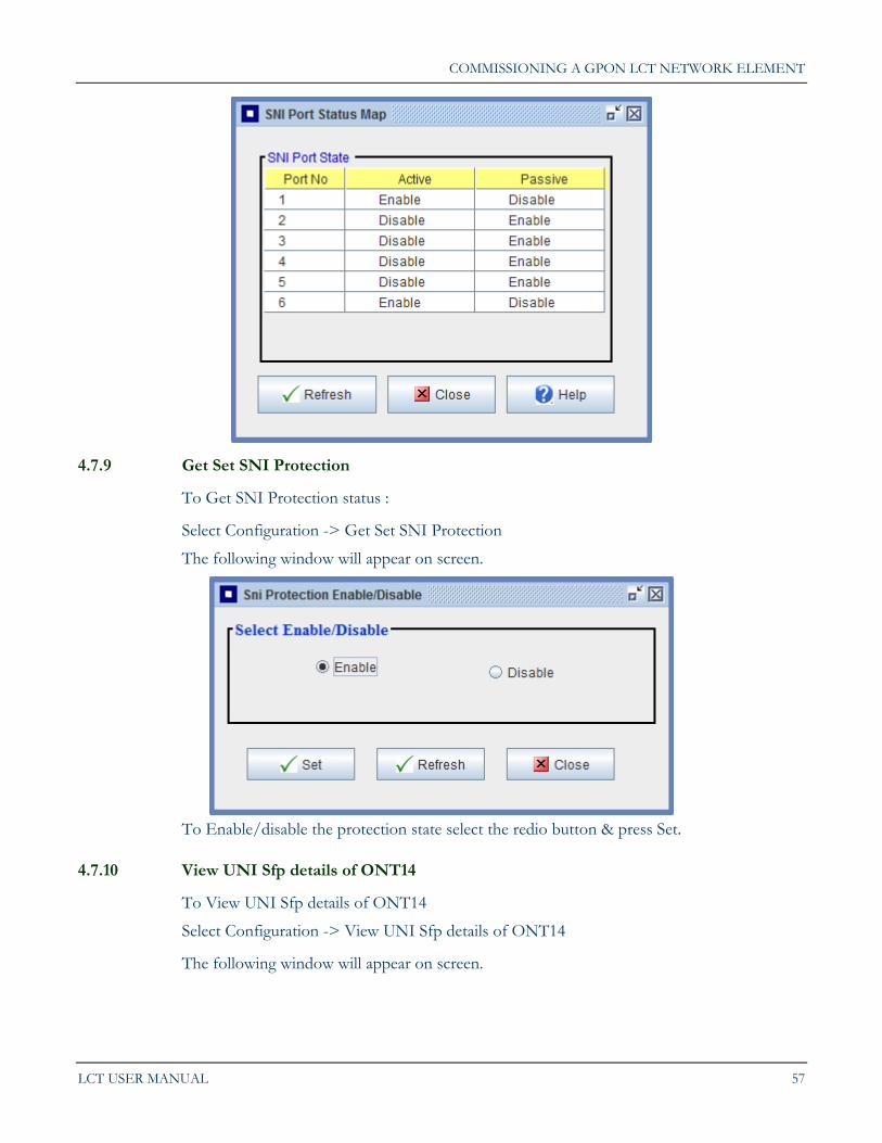
4.7.8 View SNI Port Map
To View SNI Port Map
Select Configuration -> View SNI Port map
The following window will appear on screen.
COMMISSIONING A GPON LCT NETWORK ELEMENT
LCT USER MANUAL 57
4.7.9 Get Set SNI Protection
To Get SNI Protection status :
Select Configuration -> Get Set SNI Protection
The following window will appear on screen.
To Enable/disable the protection state select the redio button & press Set.
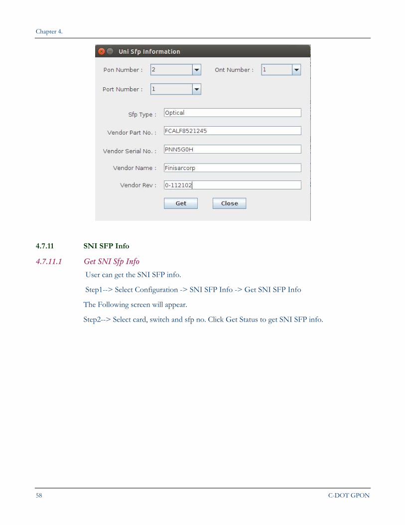
4.7.10 View UNI Sfp details of ONT14
To View UNI Sfp details of ONT14
Select Configuration -> View UNI Sfp details of ONT14
The following window will appear on screen.
Chapter 4.
58 C-DOT GPON
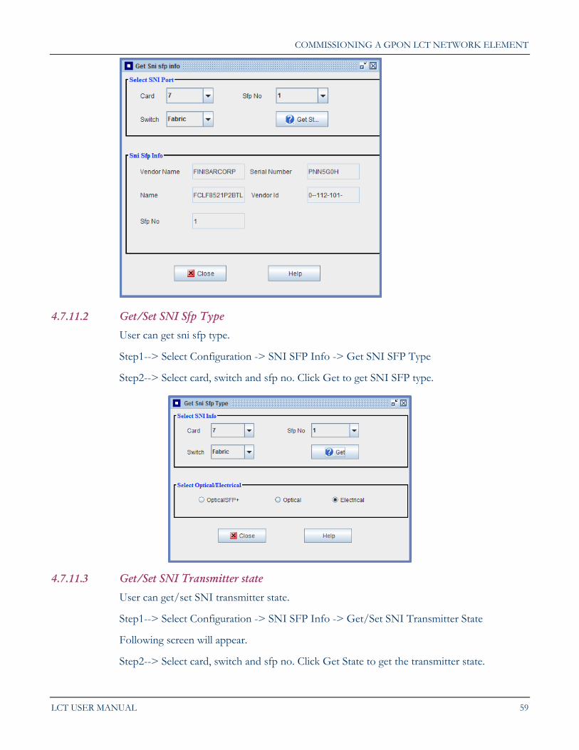
4.7.11 SNI SFP Info
4.7.11.1 Get SNI Sfp Info
User can get the SNI SFP info.
Step1--> Select Configuration -> SNI SFP Info -> Get SNI SFP Info
The Following screen will appear.
Step2--> Select card, switch and sfp no. Click Get Status to get SNI SFP info.
COMMISSIONING A GPON LCT NETWORK ELEMENT
LCT USER MANUAL 59
4.7.11.2 Get/Set SNI Sfp Type
User can get sni sfp type.
Step1--> Select Configuration -> SNI SFP Info -> Get SNI SFP Type
Step2--> Select card, switch and sfp no. Click Get to get SNI SFP type.
4.7.11.3 Get/Set SNI Transmitter state
User can get/set SNI transmitter state.
Step1--> Select Configuration -> SNI SFP Info -> Get/Set SNI Transmitter State
Following screen will appear.
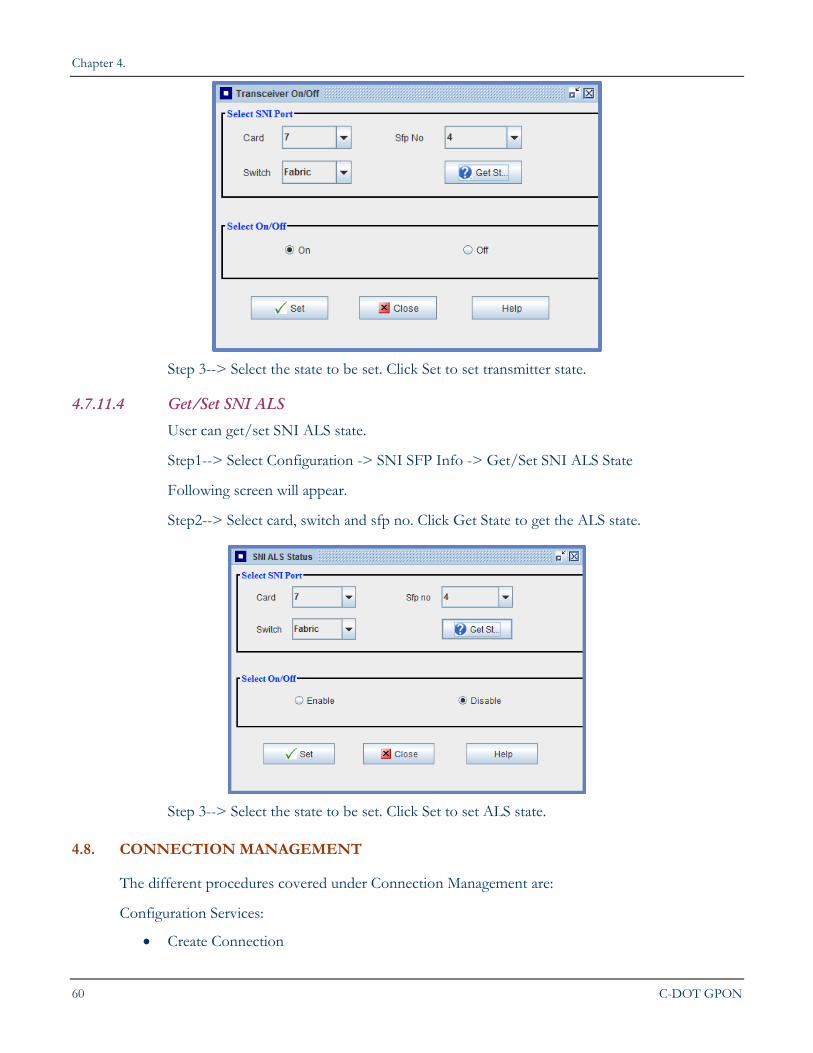
Step2--> Select card, switch and sfp no. Click Get State to get the transmitter state.
Chapter 4.
60 C-DOT GPON
Step 3--> Select the state to be set. Click Set to set transmitter state.
4.7.11.4 Get/Set SNI ALS
User can get/set SNI ALS state.
Step1--> Select Configuration -> SNI SFP Info -> Get/Set SNI ALS State
Following screen will appear.
Step2--> Select card, switch and sfp no. Click Get State to get the ALS state.
Step 3--> Select the state to be set. Click Set to set ALS state.
4.8. CONNECTION MANAGEMENT
The different procedures covered under Connection Management are:
Configuration Services:
Create Connection
COMMISSIONING A GPON LCT NETWORK ELEMENT
LCT USER MANUAL 61
View/Delete/Modify Connection
Create Profile
View/Delete/Modify Profile
VID Configuration
VOIP
Set User Profile
View Phone Number
CES
View/Modify CES Services
Get Available Bandwidth
Ether Type Configuration
OLT Net Info
COMe Connection
o Show all VLAN
o View Fabric Switch
o Modify Fabric switch
o View/Modify Mac Learning Time
o View/Modify MAC Address Learning Function
o Add Filter
o View/Delete Filter
o Configure Class of Service
Get Set Dos
IGMP Proxy Status
DHCP Status
4.8.1. Configuration Services
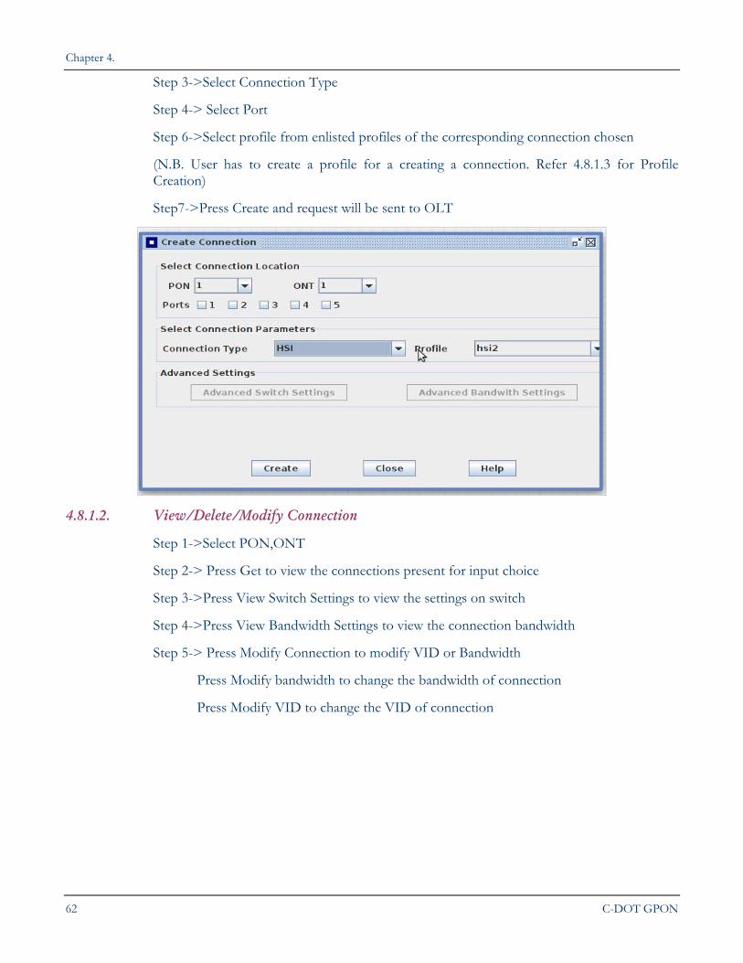
4.8.1.1. Create Connection
Step 1->Select Connection->Configure Services->Create Connection
Step 2-> Select PON, ONT
Chapter 4.
62 C-DOT GPON
Step 3->Select Connection Type
Step 4-> Select Port
Step 6->Select profile from enlisted profiles of the corresponding connection chosen
(N.B. User has to create a profile for a creating a connection. Refer 4.8.1.3 for Profile Creation)
Step7->Press Create and request will be sent to OLT
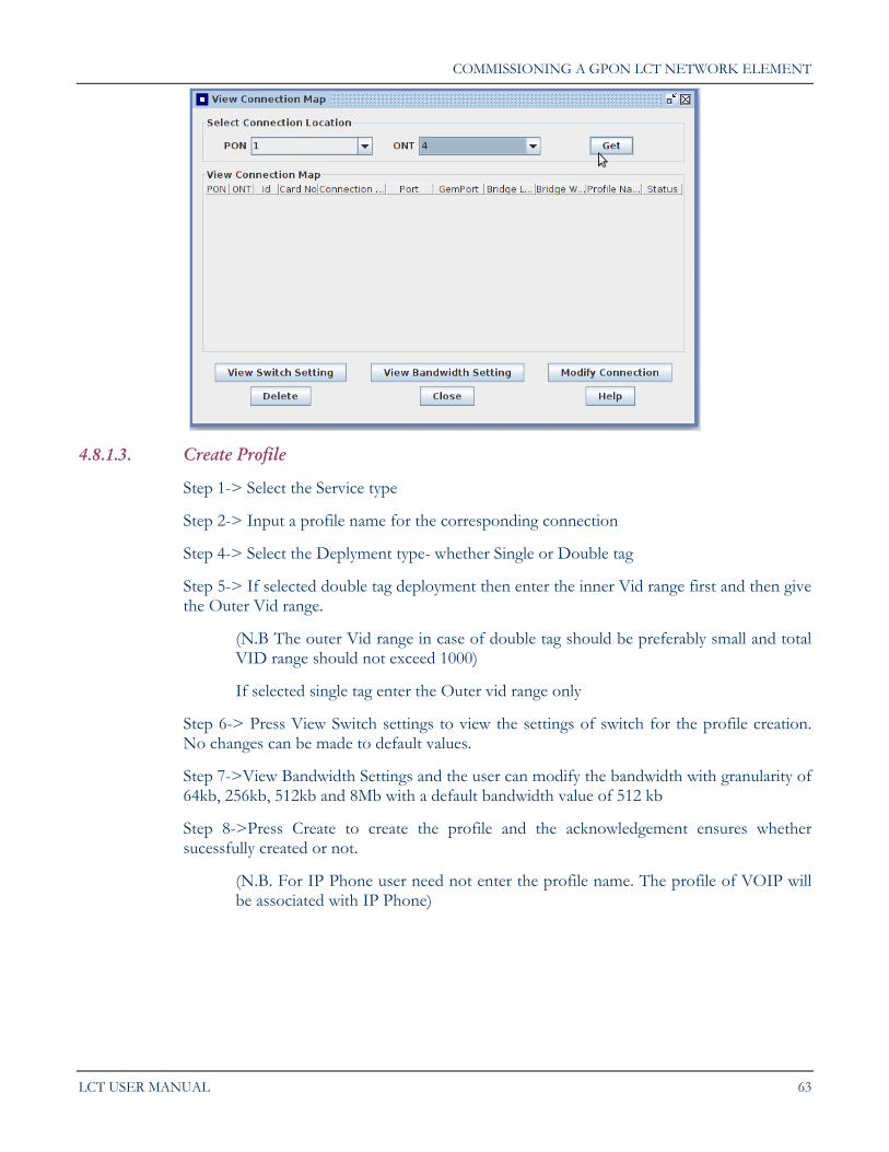
4.8.1.2. View/Delete/Modify Connection
Step 1->Select PON,ONT
Step 2-> Press Get to view the connections present for input choice
Step 3->Press View Switch Settings to view the settings on switch
Step 4->Press View Bandwidth Settings to view the connection bandwidth
Step 5-> Press Modify Connection to modify VID or Bandwidth
Press Modify bandwidth to change the bandwidth of connection
Press Modify VID to change the VID of connection
COMMISSIONING A GPON LCT NETWORK ELEMENT
LCT USER MANUAL 63
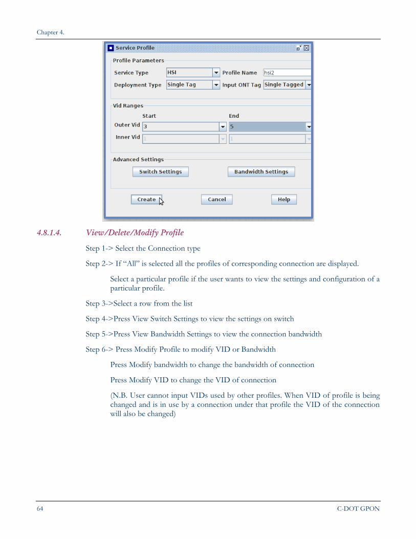
4.8.1.3. Create Profile
Step 1-> Select the Service type
Step 2-> Input a profile name for the corresponding connection
Step 4-> Select the Deplyment type- whether Single or Double tag
Step 5-> If selected double tag deployment then enter the inner Vid range first and then give the Outer Vid range.
(N.B The outer Vid range in case of double tag should be preferably small and total VID range should not exceed 1000)
If selected single tag enter the Outer vid range only
Step 6-> Press View Switch settings to view the settings of switch for the profile creation. No changes can be made to default values.
Step 7->View Bandwidth Settings and the user can modify the bandwidth with granularity of 64kb, 256kb, 512kb and 8Mb with a default bandwidth value of 512 kb
Step 8->Press Create to create the profile and the acknowledgement ensures whether sucessfully created or not.
(N.B. For IP Phone user need not enter the profile name. The profile of VOIP will be associated with IP Phone)
Chapter 4.
64 C-DOT GPON
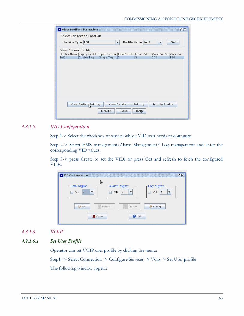
4.8.1.4. View/Delete/Modify Profile
Step 1-> Select the Connection type
Step 2-> If “All” is selected all the profiles of corresponding connection are displayed.
Select a particular profile if the user wants to view the settings and configuration of a particular profile.
Step 3->Select a row from the list
Step 4->Press View Switch Settings to view the settings on switch
Step 5->Press View Bandwidth Settings to view the connection bandwidth
Step 6-> Press Modify Profile to modify VID or Bandwidth
Press Modify bandwidth to change the bandwidth of connection
Press Modify VID to change the VID of connection
(N.B. User cannot input VIDs used by other profiles. When VID of profile is being changed and is in use by a connection under that profile the VID of the connection will also be changed)
COMMISSIONING A GPON LCT NETWORK ELEMENT
LCT USER MANUAL 65
4.8.1.5. VID Configuration
Step 1-> Select the checkbox of service whose VID user needs to configure.
Step 2-> Select EMS management/Alarm Management/ Log management and enter the corresponding VID values.
Step 3-> press Create to set the VIDs or press Get and refresh to fetch the configured VIDs.
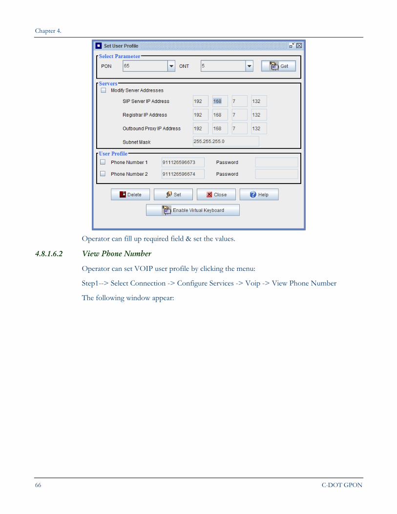
4.8.1.6. VOIP
4.8.1.6.1 Set User Profile
Operator can set VOIP user profile by clicking the menu:
Step1--> Select Connection -> Configure Services -> Voip -> Set User profile
The following window appear:
Chapter 4.
66 C-DOT GPON
Operator can fill up required field & set the values.
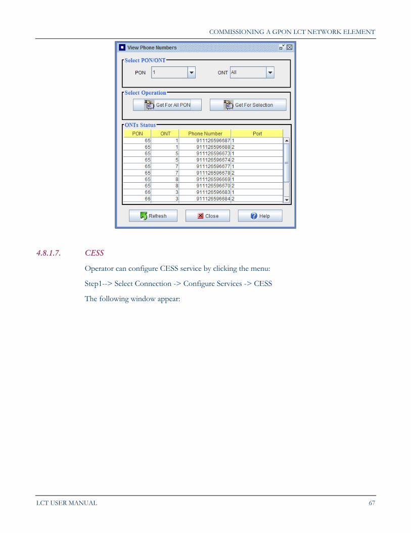
4.8.1.6.2 View Phone Number
Operator can set VOIP user profile by clicking the menu:
Step1--> Select Connection -> Configure Services -> Voip -> View Phone Number
The following window appear:
COMMISSIONING A GPON LCT NETWORK ELEMENT
LCT USER MANUAL 67
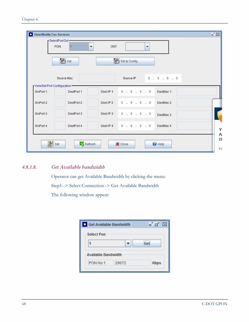
4.8.1.7. CESS
Operator can configure CESS service by clicking the menu:
Step1--> Select Connection -> Configure Services -> CESS
The following window appear:
Chapter 4.
68 C-DOT GPON
4.8.1.8. Get Available bandwidth
Operator can get Available Bandwidth by clicking the menu:
Step1--> Select Connection -> Get Available Bandwidth
The following window appear:
COMMISSIONING A GPON LCT NETWORK ELEMENT
LCT USER MANUAL 69
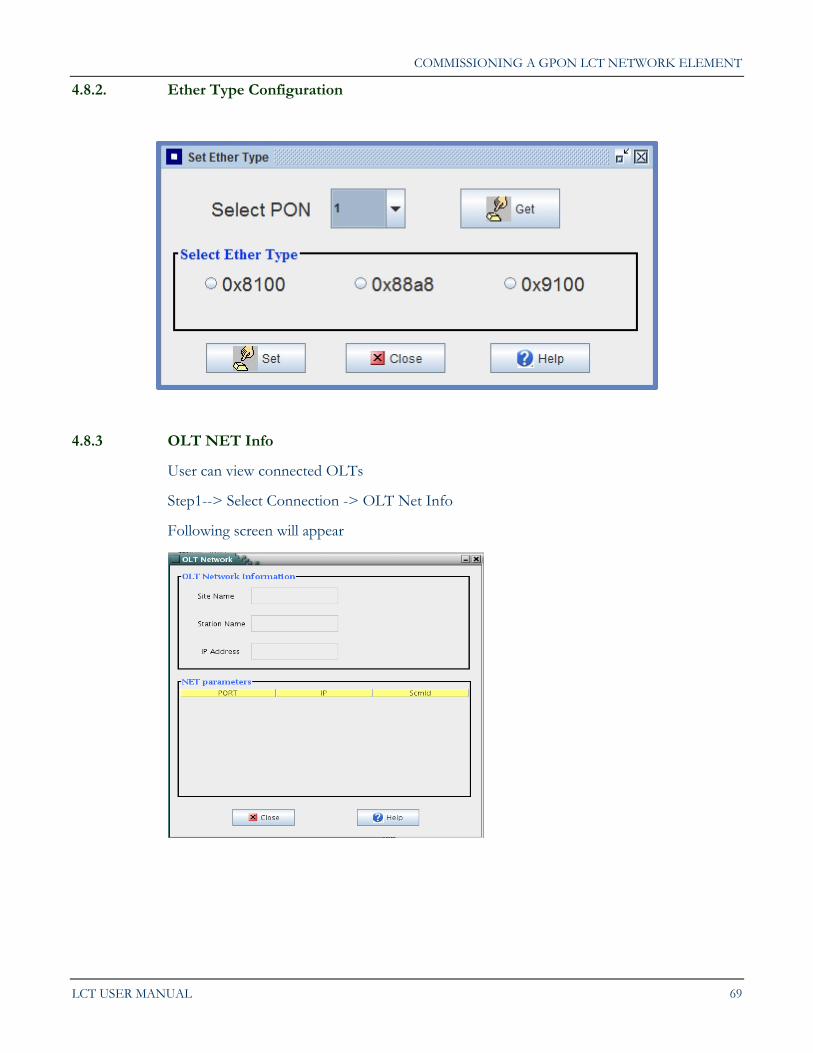
4.8.2. Ether Type Configuration
4.8.3 OLT NET Info
User can view connected OLTs
Step1--> Select Connection -> OLT Net Info
Following screen will appear
Chapter 4.
70 C-DOT GPON
4.8.4 COMe Connection
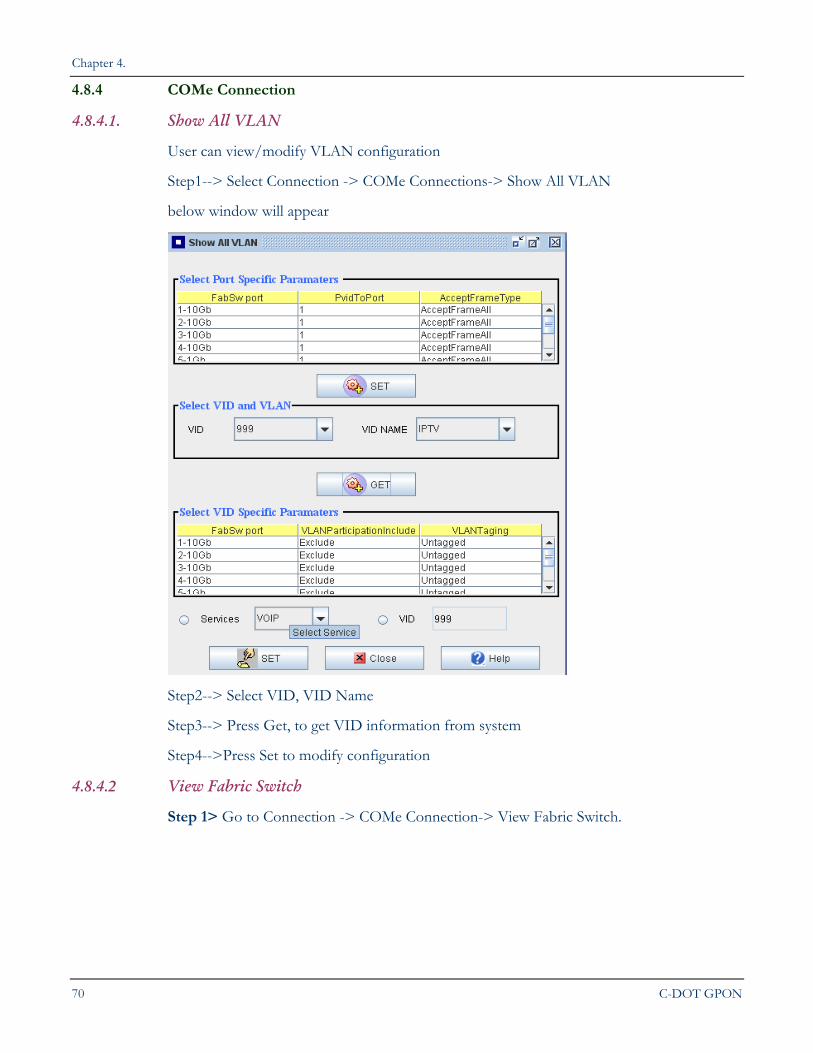
4.8.4.1. Show All VLAN
User can view/modify VLAN configuration
Step1--> Select Connection -> COMe Connections-> Show All VLAN
below window will appear
Step2--> Select VID, VID Name
Step3--> Press Get, to get VID information from system
Step4-->Press Set to modify configuration
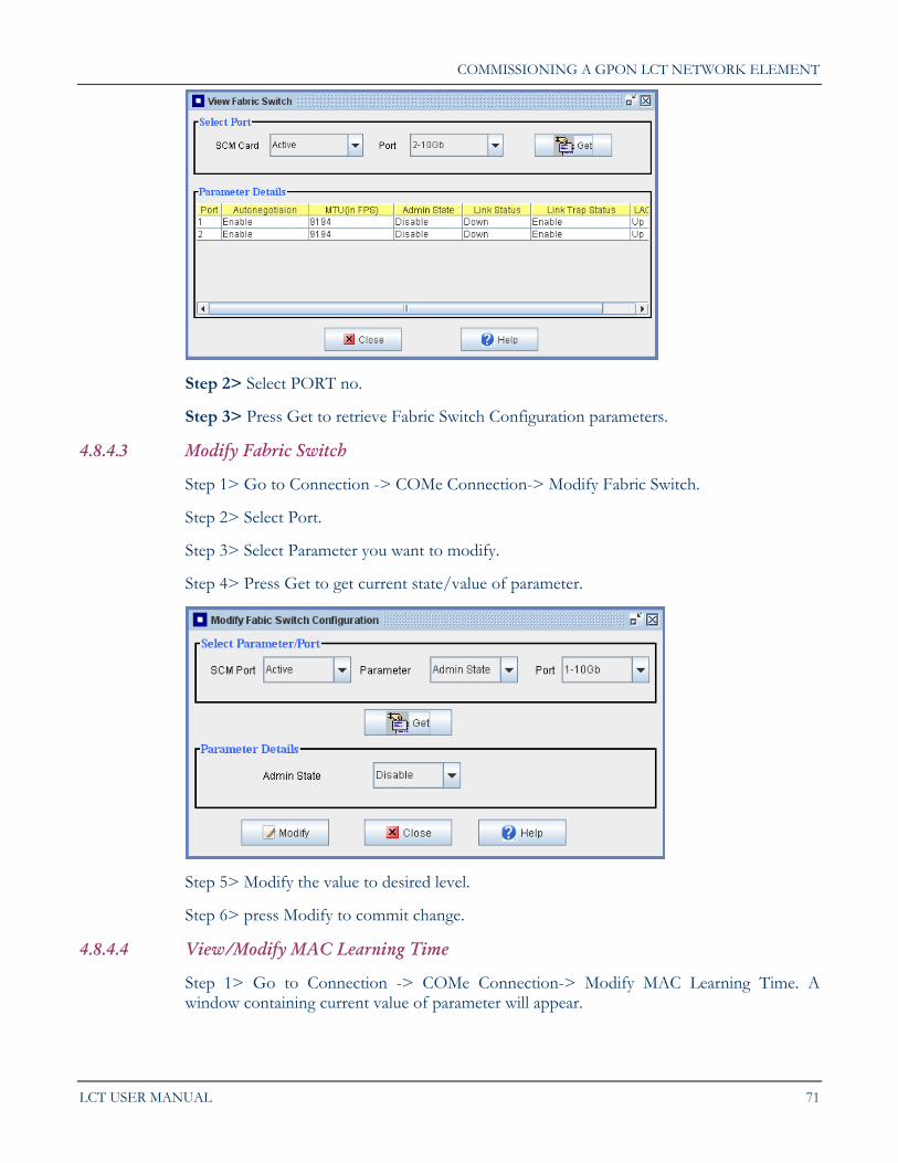
4.8.4.2 View Fabric Switch
Step 1> Go to Connection -> COMe Connection-> View Fabric Switch.
COMMISSIONING A GPON LCT NETWORK ELEMENT
LCT USER MANUAL 71
Step 2> Select PORT no.
Step 3> Press Get to retrieve Fabric Switch Configuration parameters.
4.8.4.3 Modify Fabric Switch
Step 1> Go to Connection -> COMe Connection-> Modify Fabric Switch.
Step 2> Select Port.
Step 3> Select Parameter you want to modify.
Step 4> Press Get to get current state/value of parameter.
Step 5> Modify the value to desired level.
Step 6> press Modify to commit change.
4.8.4.4 View/Modify MAC Learning Time
Step 1> Go to Connection -> COMe Connection-> Modify MAC Learning Time. A window containing current value of parameter will appear.
Chapter 4.
72 C-DOT GPON
Step 2> Modify the value to your desired level.
Step 3> Press Modify.
4.8.4.5 View Modify MAC Address Learning Function
Step 1> Go to Connection -> COMe Connection-> Modify MAC Address Learning Function.
Step2 > Select Port.
Step 3> Press Get to get current state of function.
Step 4> Change the value and press Modify.
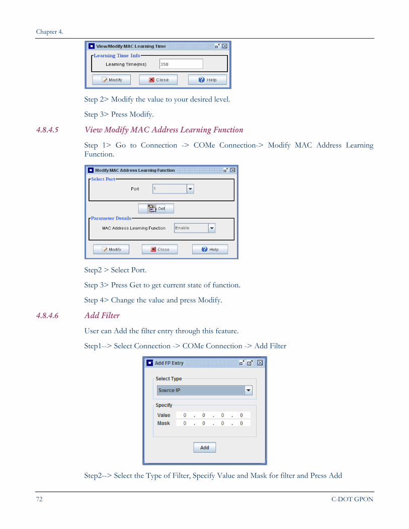
4.8.4.6 Add Filter
User can Add the filter entry through this feature.
Step1--> Select Connection -> COMe Connection -> Add Filter
Step2--> Select the Type of Filter, Specify Value and Mask for filter and Press Add
COMMISSIONING A GPON LCT NETWORK ELEMENT
LCT USER MANUAL 73
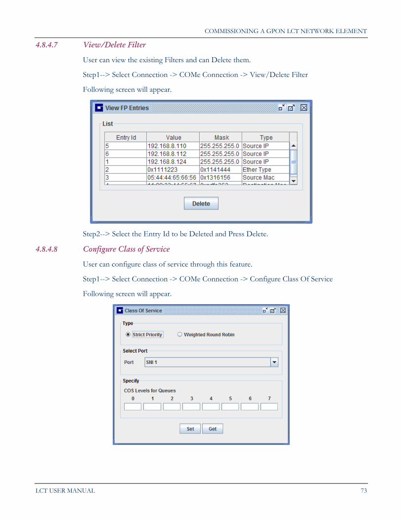
4.8.4.7 View/Delete Filter
User can view the existing Filters and can Delete them.
Step1--> Select Connection -> COMe Connection -> View/Delete Filter
Following screen will appear.
Step2--> Select the Entry Id to be Deleted and Press Delete.
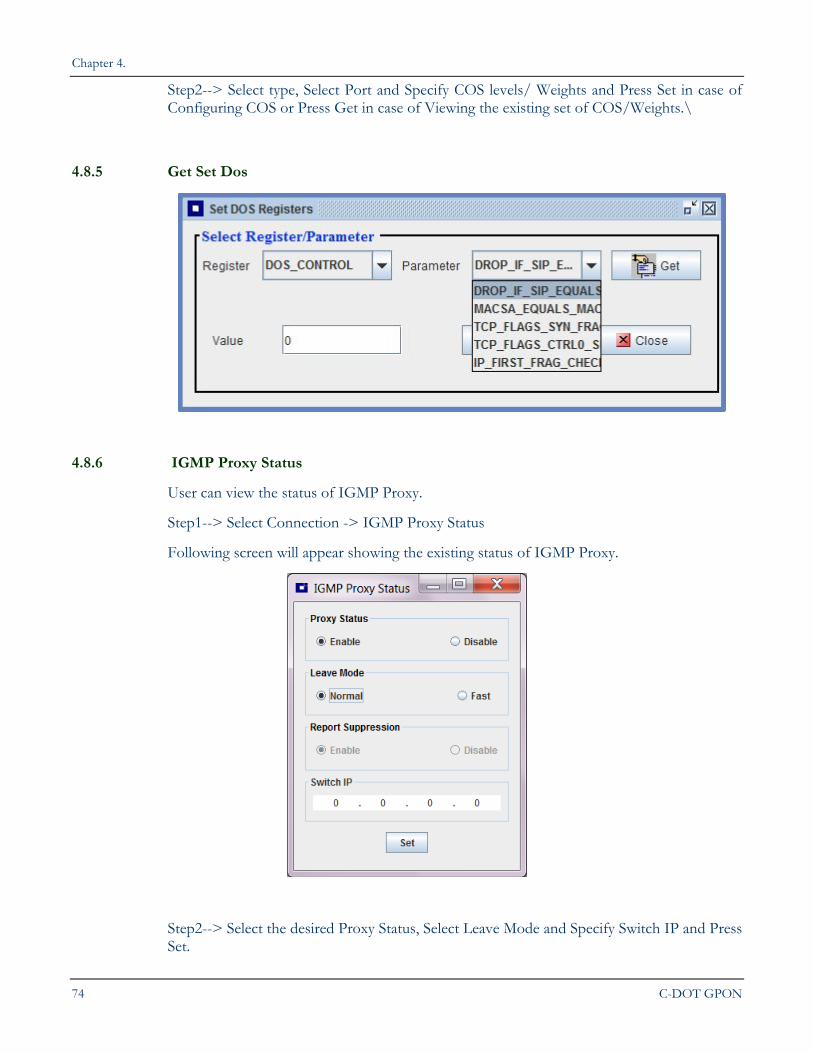
4.8.4.8 Configure Class of Service
User can configure class of service through this feature.
Step1--> Select Connection -> COMe Connection -> Configure Class Of Service
Following screen will appear.
Chapter 4.
74 C-DOT GPON
Step2--> Select type, Select Port and Specify COS levels/ Weights and Press Set in case of Configuring COS or Press Get in case of Viewing the existing set of COS/Weights.\
4.8.5 Get Set Dos
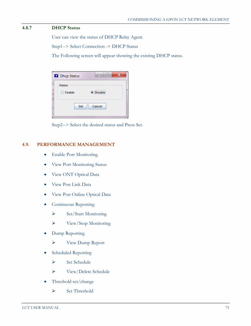
4.8.6 IGMP Proxy Status
User can view the status of IGMP Proxy.
Step1--> Select Connection -> IGMP Proxy Status
Following screen will appear showing the existing status of IGMP Proxy.
Step2--> Select the desired Proxy Status, Select Leave Mode and Specify Switch IP and Press Set.
COMMISSIONING A GPON LCT NETWORK ELEMENT
LCT USER MANUAL 75
4.8.7 DHCP Status
User can view the status of DHCP Relay Agent.
Step1--> Select Connection -> DHCP Status
The Following screen will appear showing the existing DHCP status.
Step2--> Select the desired status and Press Set.
4.9. PERFORMANCE MANAGEMENT
Enable Port Monitoring
View Port Monitoring Status
View ONT Optical Data
View Pon Link Data
View Pon Online Optical Data
Continuous Reporting
Set/Start Monitoring
View/Stop Monitoring
Dump Reporting
View Dump Report
Scheduled Reporting
Set Schedule
View/Delete Schedule
Threshold set/change
Set Threshold
Chapter 4.
76 C-DOT GPON
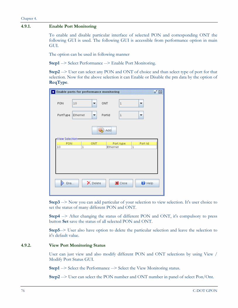
4.9.1. Enable Port Monitoring
To enable and disable particular interface of selected PON and corresponding ONT the following GUI is used. The following GUI is accessible from performance option in main GUI.
The option can be used in following manner
Step1 --> Select Performance --> Enable Port Monitoring.
Step2 --> User can select any PON and ONT of choice and than select type of port for that selection. Now for the above selection it can Enable or Disable the pm data by the option of ReqType.
Step3 --> Now you can add particular of your selection to view selection. It's user choice to set the status of many different PON and ONT.
Step4 --> After changing the status of different PON and ONT, it's compulsory to press button Set save the status of all selected PON and ONT.
Step5--> User also have option to delete the particular selection and leave the selection to it's default value.
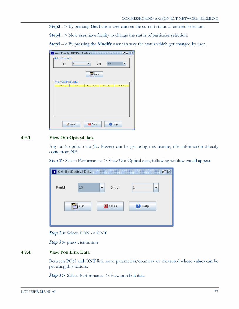
4.9.2. View Port Monitoring Status
User can just view and also modify different PON and ONT selections by using View / Modify Port Status GUI.
Step1 --> Select the Performance --> Select the View Monitoring status.
Step2 --> User can select the PON number and ONT number in panel of select Pon/Ont.
COMMISSIONING A GPON LCT NETWORK ELEMENT
LCT USER MANUAL 77
Step3 --> By pressing Get button user can see the current status of entered selection.
Step4 --> Now user have facility to change the status of particular selection.
Step5 --> By pressing the Modify user can save the status which got changed by user.
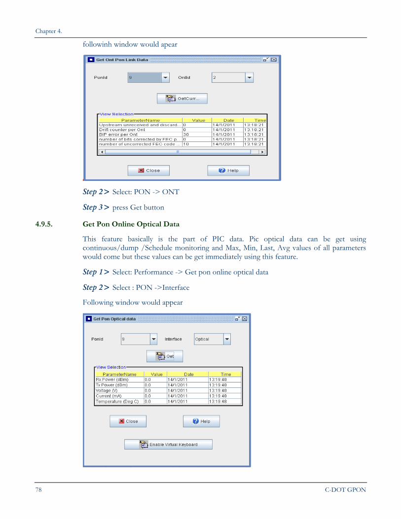
4.9.3. View Ont Optical data
Any ont's optical data (Rx Power) can be get using this feature, this information directly come from NE.
Step 1> Select: Performance -> View Ont Optical data, following window would appear
Step 2> Select: PON -> ONT
Step 3> press Get button
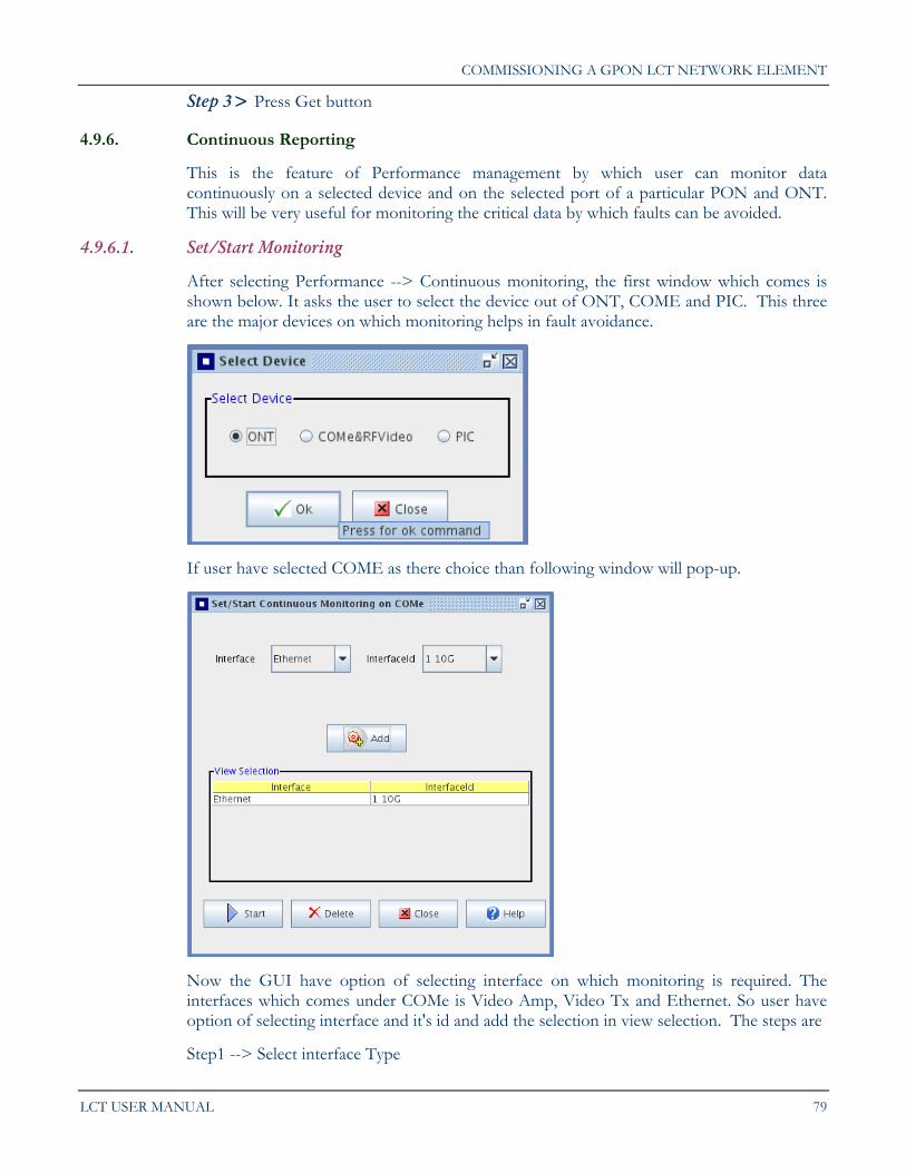
4.9.4. View Pon Link Data
Between PON and ONT link some parameters/counters are measured whose values can be get using this feature.
Step 1> Select: Performance -> View pon link data
Chapter 4.
78 C-DOT GPON
followinh window would apear
Step 2> Select: PON -> ONT
Step 3> press Get button
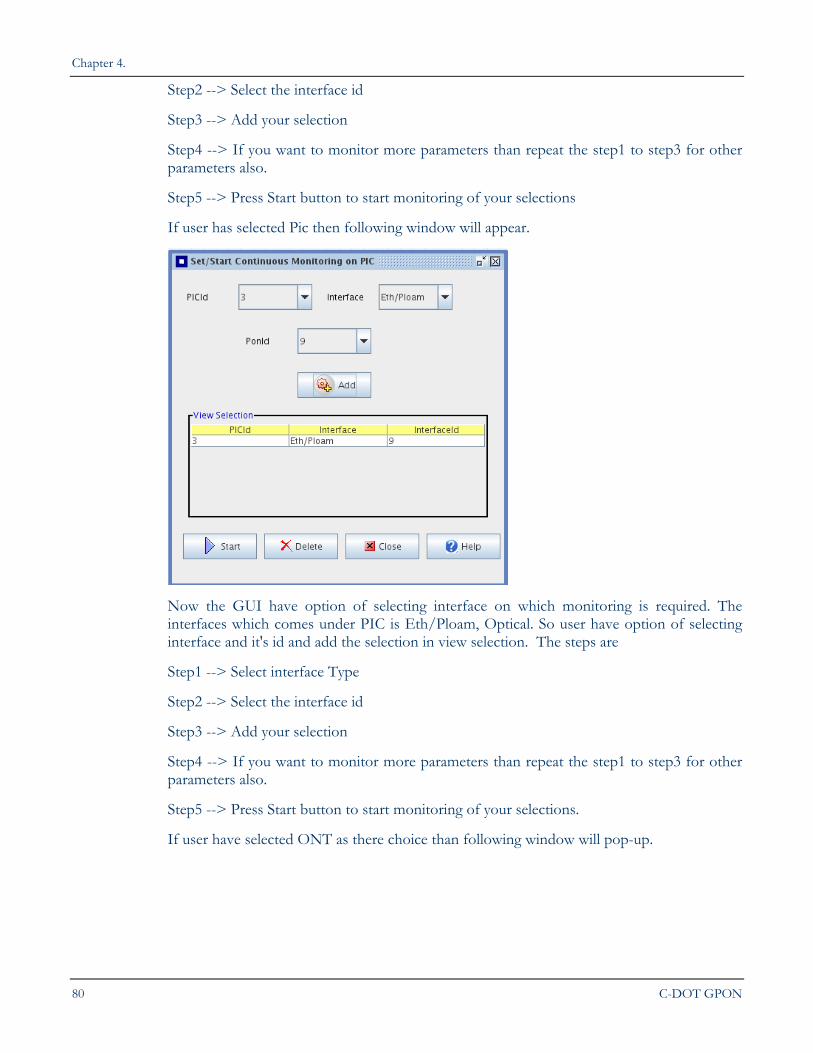
4.9.5. Get Pon Online Optical Data
This feature basically is the part of PIC data. Pic optical data can be get using continuous/dump /Schedule monitoring and Max, Min, Last, Avg values of all parameters would come but these values can be get immediately using this feature.
Step 1> Select: Performance -> Get pon online optical data
Step 2> Select : PON ->Interface
Following window would appear
COMMISSIONING A GPON LCT NETWORK ELEMENT
LCT USER MANUAL 79
Step 3> Press Get button
4.9.6. Continuous Reporting
This is the feature of Performance management by which user can monitor data continuously on a selected device and on the selected port of a particular PON and ONT. This will be very useful for monitoring the critical data by which faults can be avoided.
4.9.6.1. Set/Start Monitoring
After selecting Performance --> Continuous monitoring, the first window which comes is shown below. It asks the user to select the device out of ONT, COME and PIC. This three are the major devices on which monitoring helps in fault avoidance.
If user have selected COME as there choice than following window will pop-up.
Now the GUI have option of selecting interface on which monitoring is required. The interfaces which comes under COMe is Video Amp, Video Tx and Ethernet. So user have option of selecting interface and it's id and add the selection in view selection. The steps are
Step1 --> Select interface Type
Chapter 4.
80 C-DOT GPON
Step2 --> Select the interface id
Step3 --> Add your selection
Step4 --> If you want to monitor more parameters than repeat the step1 to step3 for other parameters also.
Step5 --> Press Start button to start monitoring of your selections
If user has selected Pic then following window will appear.
Now the GUI have option of selecting interface on which monitoring is required. The interfaces which comes under PIC is Eth/Ploam, Optical. So user have option of selecting interface and it's id and add the selection in view selection. The steps are
Step1 --> Select interface Type
Step2 --> Select the interface id
Step3 --> Add your selection
Step4 --> If you want to monitor more parameters than repeat the step1 to step3 for other parameters also.
Step5 --> Press Start button to start monitoring of your selections.
If user have selected ONT as there choice than following window will pop-up.
COMMISSIONING A GPON LCT NETWORK ELEMENT
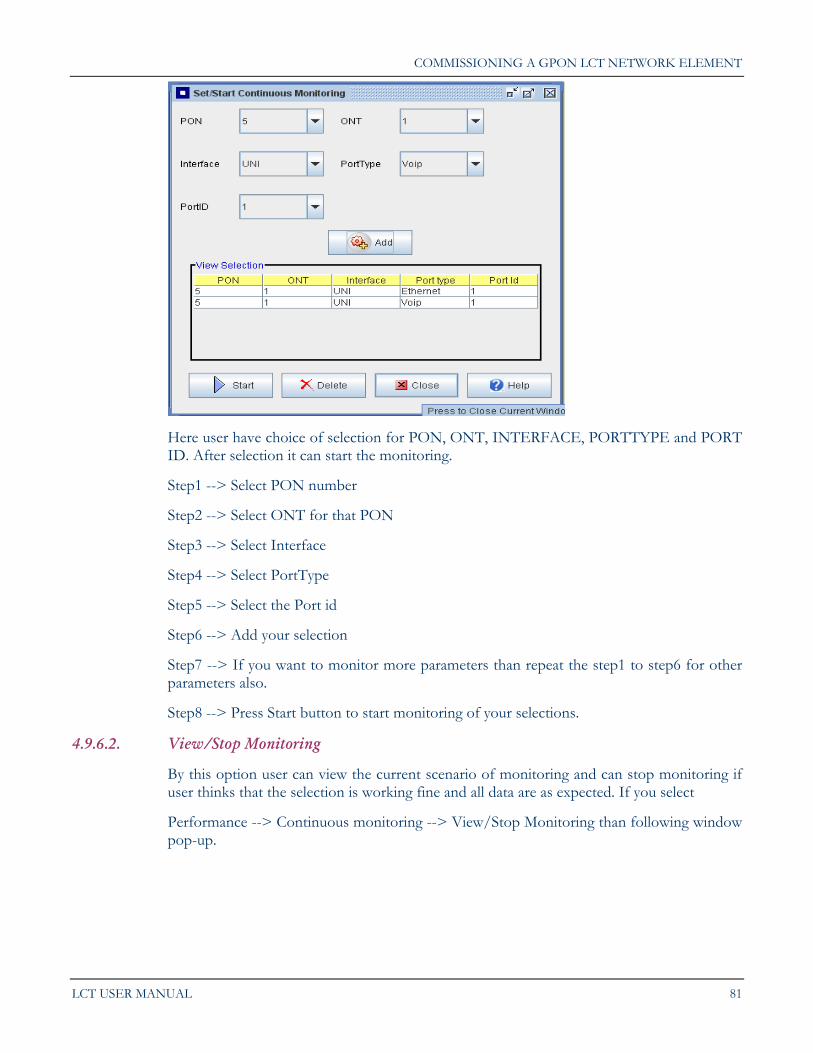
LCT USER MANUAL 81
Here user have choice of selection for PON, ONT, INTERFACE, PORTTYPE and PORT ID. After selection it can start the monitoring.
Step1 --> Select PON number
Step2 --> Select ONT for that PON
Step3 --> Select Interface
Step4 --> Select PortType
Step5 --> Select the Port id
Step6 --> Add your selection
Step7 --> If you want to monitor more parameters than repeat the step1 to step6 for other parameters also.
Step8 --> Press Start button to start monitoring of your selections.
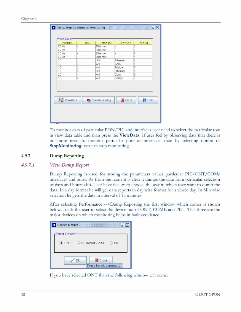
4.9.6.2. View/Stop Monitoring
By this option user can view the current scenario of monitoring and can stop monitoring if user thinks that the selection is working fine and all data are as expected. If you select
Performance --> Continuous monitoring --> View/Stop Monitoring than following window pop-up.
Chapter 4.
82 C-DOT GPON
To monitor data of particular PON/PIC and interfaces user need to select the particular row in view data table and than press the ViewData. If user feel by observing data that there is no more need to monitor particular port or interfaces than by selecting option of StopMonitoring user can stop monitoring.
4.9.7. Dump Reporting
4.9.7.1. View Dump Report
Dump Reporting is used for storing the parameters values particular PIC/ONT/COMe interfaces and ports. As from the name it is clear it dumps the data for a particular selection of days and hours also. User have facility to choose the way in which user want to dump the data. In a day format he will get data reports in day wise format for a whole day. In Min wise selection he gets the data in interval of 15 minutes.
After selecting Performance -->Dump Reporting the first window which comes is shown below. It ask the user to select the device out of ONT, COME and PIC. This three are the major devices on which monitoring helps in fault avoidance.
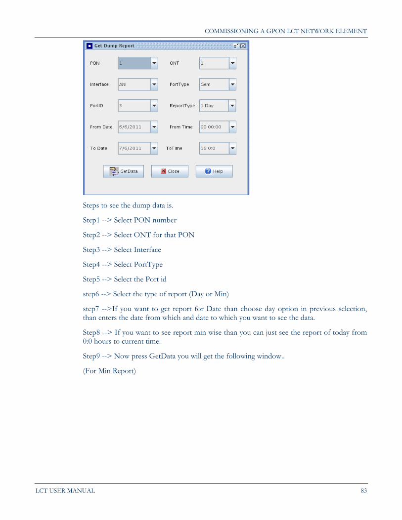
If you have selected ONT than the following window will come.
COMMISSIONING A GPON LCT NETWORK ELEMENT
LCT USER MANUAL 83
Steps to see the dump data is.
Step1 --> Select PON number
Step2 --> Select ONT for that PON
Step3 --> Select Interface
Step4 --> Select PortType
Step5 --> Select the Port id
step6 --> Select the type of report (Day or Min)
step7 -->If you want to get report for Date than choose day option in previous selection, than enters the date from which and date to which you want to see the data.
Step8 --> If you want to see report min wise than you can just see the report of today from 0:0 hours to current time.
Step9 --> Now press GetData you will get the following window..
(For Min Report)
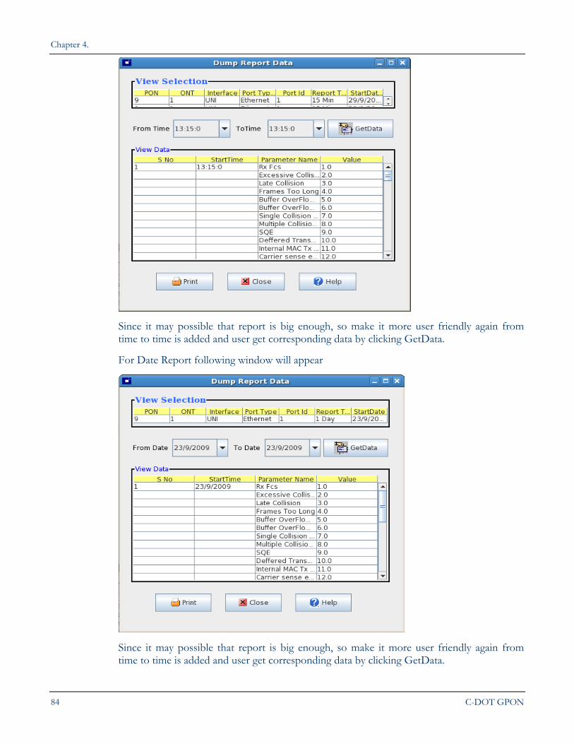
Chapter 4.
84 C-DOT GPON
Since it may possible that report is big enough, so make it more user friendly again from time to time is added and user get corresponding data by clicking GetData.
For Date Report following window will appear
Since it may possible that report is big enough, so make it more user friendly again from time to time is added and user get corresponding data by clicking GetData.
COMMISSIONING A GPON LCT NETWORK ELEMENT
LCT USER MANUAL 85
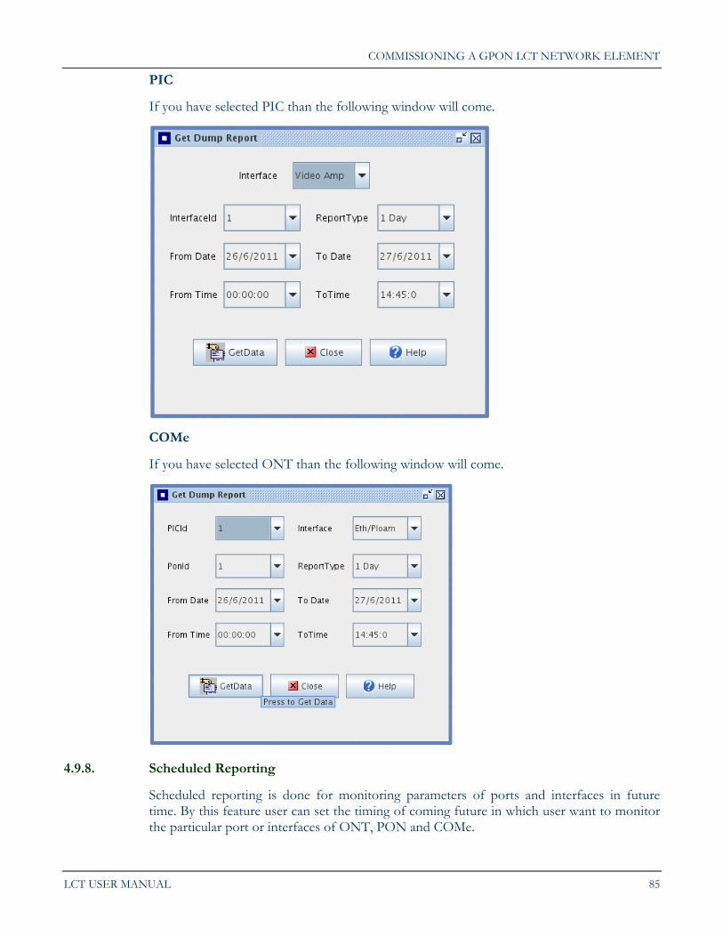
PIC
If you have selected PIC than the following window will come.
COMe
If you have selected ONT than the following window will come.
4.9.8. Scheduled Reporting
Scheduled reporting is done for monitoring parameters of ports and interfaces in future time. By this feature user can set the timing of coming future in which user want to monitor the particular port or interfaces of ONT, PON and COMe.
Chapter 4.
86 C-DOT GPON
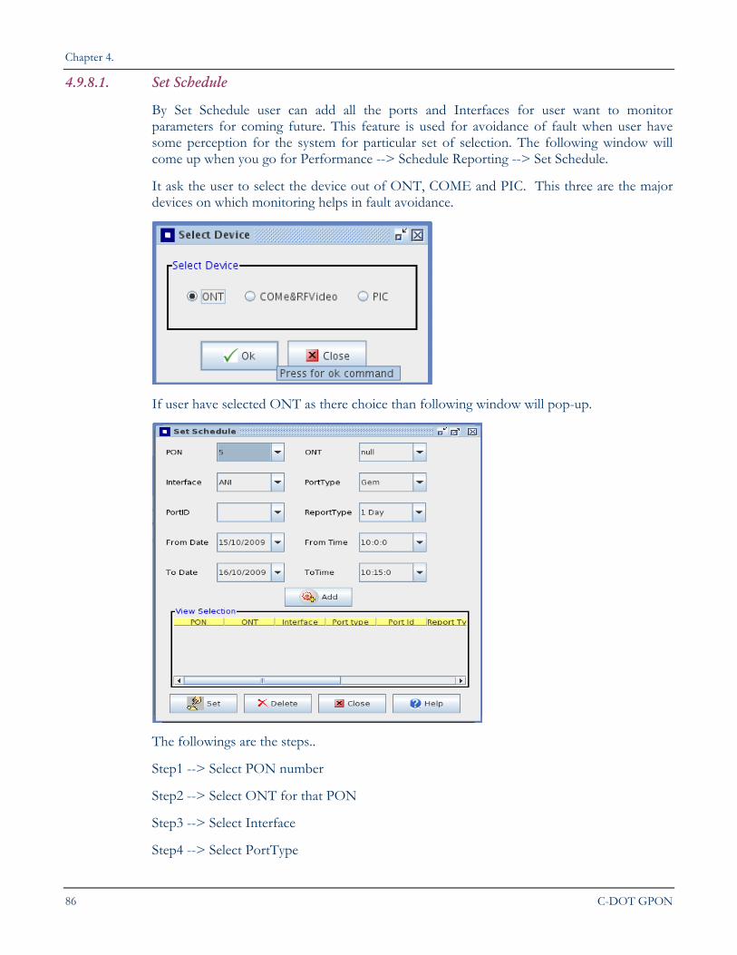
4.9.8.1. Set Schedule
By Set Schedule user can add all the ports and Interfaces for user want to monitor parameters for coming future. This feature is used for avoidance of fault when user have some perception for the system for particular set of selection. The following window will come up when you go for Performance --> Schedule Reporting --> Set Schedule.
It ask the user to select the device out of ONT, COME and PIC. This three are the major devices on which monitoring helps in fault avoidance.
If user have selected ONT as there choice than following window will pop-up.
The followings are the steps..
Step1 --> Select PON number
Step2 --> Select ONT for that PON
Step3 --> Select Interface
Step4 --> Select PortType
COMMISSIONING A GPON LCT NETWORK ELEMENT
LCT USER MANUAL 87
Step5 --> Select the Port id
Step6 --> Select the type of report (Day or Min) Step7 -->If you want to get report for Date than choose day option in previous selection, than enters the date from which and date to which you want to see the data.
NOTE: Here from date is starts from today date and to date starts from date after today so all date in todate is future dates only.
Step8 --> If you want to see report min wise than you can just see the report of today from current time to all future time of today.
Step9 --> User also have facility to add many parameters which he user want to monitoring by simply pressing ADD button. The panel below shows the all current selection for monitoring.
Step10 --> Now press Set to enable the monitoring of parameters in future time.
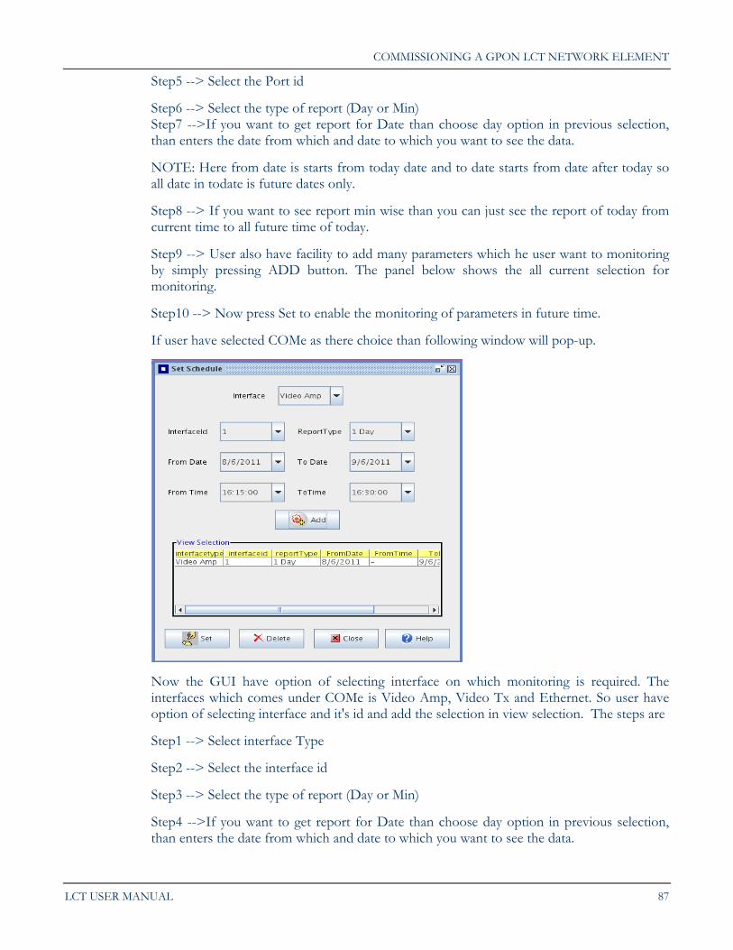
If user have selected COMe as there choice than following window will pop-up.
Now the GUI have option of selecting interface on which monitoring is required. The interfaces which comes under COMe is Video Amp, Video Tx and Ethernet. So user have option of selecting interface and it's id and add the selection in view selection. The steps are
Step1 --> Select interface Type
Step2 --> Select the interface id
Step3 --> Select the type of report (Day or Min)
Step4 -->If you want to get report for Date than choose day option in previous selection, than enters the date from which and date to which you want to see the data.
Chapter 4.
88 C-DOT GPON
NOTE: Here from date is starts from today date and to date starts from date after today so all date in todate is future dates only.
Step5 --> If you want to see report min wise than you can just see the report of today from current time to all future time of today.
Step6 --> User also have facility to add many parameters which he user want to monitoring by simply pressing ADD button. The panel below shows the all current selection for monitoring.
Step7 --> Now press Set to enable the monitoring of parameters in future time.
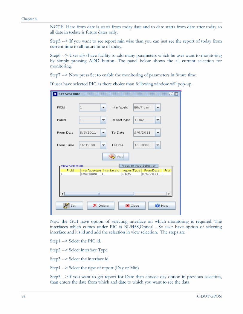
If user have selected PIC as there choice than following window will pop-up.
Now the GUI have option of selecting interface on which monitoring is required. The interfaces which comes under PIC is BL3458,Optical . So user have option of selecting interface and it's id and add the selection in view selection. The steps are
Step1 --> Select the PIC id.
Step2 --> Select interface Type
Step3 --> Select the interface id
Step4 --> Select the type of report (Day or Min)
Step5 -->If you want to get report for Date than choose day option in previous selection, than enters the date from which and date to which you want to see the data.
COMMISSIONING A GPON LCT NETWORK ELEMENT
LCT USER MANUAL 89
NOTE: Here from date is starts from today date and to date starts from date after today so all date in todate is future dates only.
Step6 --> If you want to see report min wise than you can just see the report of today from current time to all future time of today.
Step7 --> User also have facility to add many parameters which he user want to monitoring by simply pressing ADD button. The panel below shows the all current selection for monitoring.
Step8 --> Now press Set to enable the monitoring of parameters in future time.
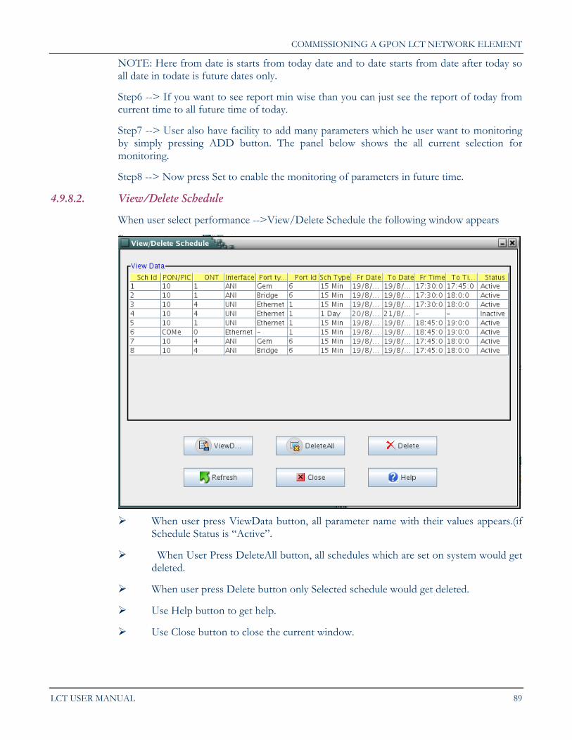
4.9.8.2. View/Delete Schedule
When user select performance -->View/Delete Schedule the following window appears
When user press ViewData button, all parameter name with their values appears.(if
Schedule Status is “Active”.
When User Press DeleteAll button, all schedules which are set on system would get deleted.
When user press Delete button only Selected schedule would get deleted.
Use Help button to get help.
Use Close button to close the current window.
Chapter 4.
90 C-DOT GPON
4.9.9. Threshold set/change
This option is given to user to monitor the threshold value of the different parameter and also user can change the threshold values of different parameters. The threshold values are given to system so that if certain parameter crosses the values than it will generate the alarm and notify the administrator about this so that fault can be avoided.
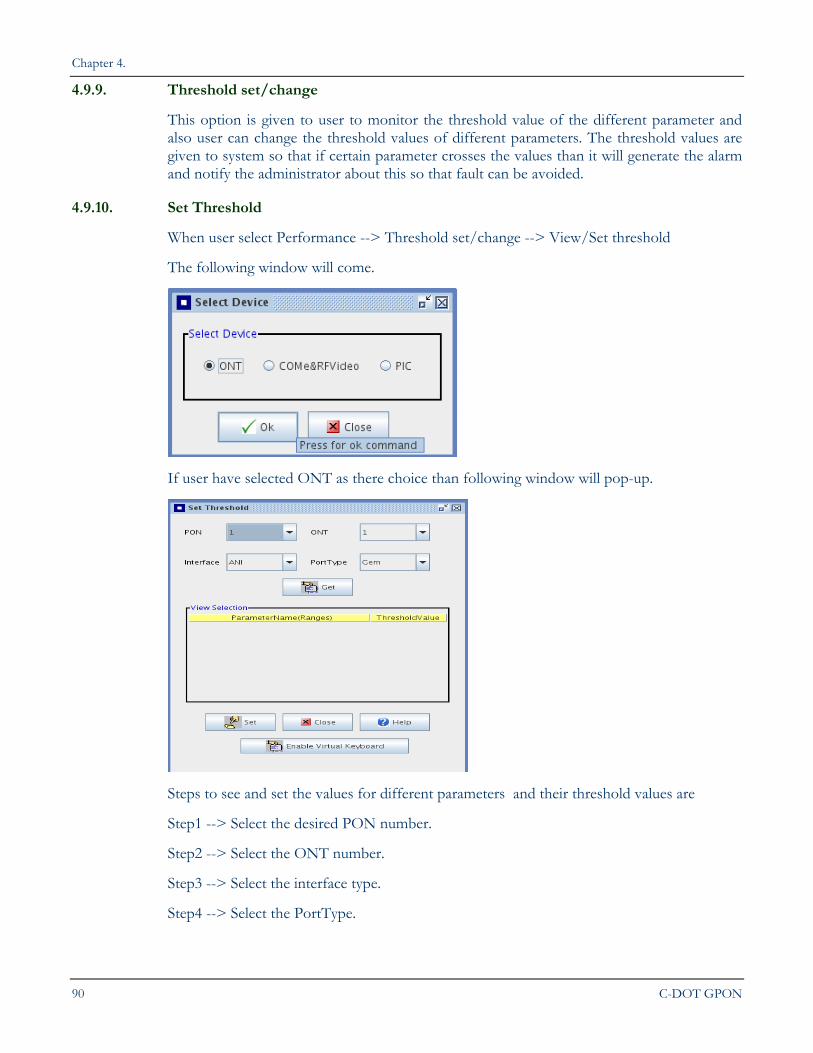
4.9.10. Set Threshold
When user select Performance --> Threshold set/change --> View/Set threshold
The following window will come.
If user have selected ONT as there choice than following window will pop-up.
Steps to see and set the values for different parameters and their threshold values are
Step1 --> Select the desired PON number.
Step2 --> Select the ONT number.
Step3 --> Select the interface type.
Step4 --> Select the PortType.
COMMISSIONING A GPON LCT NETWORK ELEMENT
LCT USER MANUAL 91
Step5 --> Press Get button to see all the parameters related to your selections. Now user can see the thresholds parameters and if user want to change the values than user can change it.
Step6 --> If user has change the thresholds values than it compulsory to press the Set button so that modification takes effects.
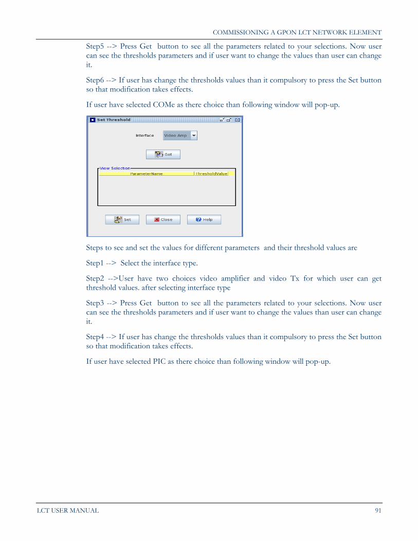
If user have selected COMe as there choice than following window will pop-up.
Steps to see and set the values for different parameters and their threshold values are
Step1 --> Select the interface type.
Step2 -->User have two choices video amplifier and video Tx for which user can get threshold values. after selecting interface type
Step3 --> Press Get button to see all the parameters related to your selections. Now user can see the thresholds parameters and if user want to change the values than user can change it.
Step4 --> If user has change the thresholds values than it compulsory to press the Set button so that modification takes effects.
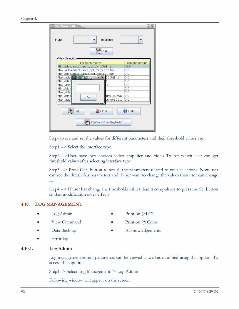
If user have selected PIC as there choice than following window will pop-up.
Chapter 4.
92 C-DOT GPON
Steps to see and set the values for different parameters and their threshold values are
Step1 --> Select the interface type.
Step2 -->User have two choices video amplifier and video Tx for which user can get threshold values after selecting interface type
Step3 --> Press Get button to see all the parameters related to your selections. Now user can see the thresholds parameters and if user want to change the values than user can change it.
Step4 --> If user has change the thresholds values than it compulsory to press the Set button so that modification takes effects.
4.10. LOG MANAGEMENT
Log Admin Print on @LCT
View Command Print on @ Come
Data Back up Acknowledgements
Error log
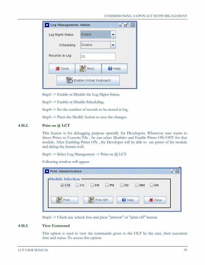
4.10.1. Log Admin
Log management admin parameters can be viewed as well as modified using this option. To access this option:
Step1--> Select Log Management -> Log Admin
Following window will appear on the screen.
COMMISSIONING A GPON LCT NETWORK ELEMENT
LCT USER MANUAL 93
Step2--> Enable or Disable the Log Mgmt Status.
Step3--> Enable or Disable Scheduling.
Step4--> Set the number of records to be stored in log.
Step5--> Press the Modify button to save the changes.
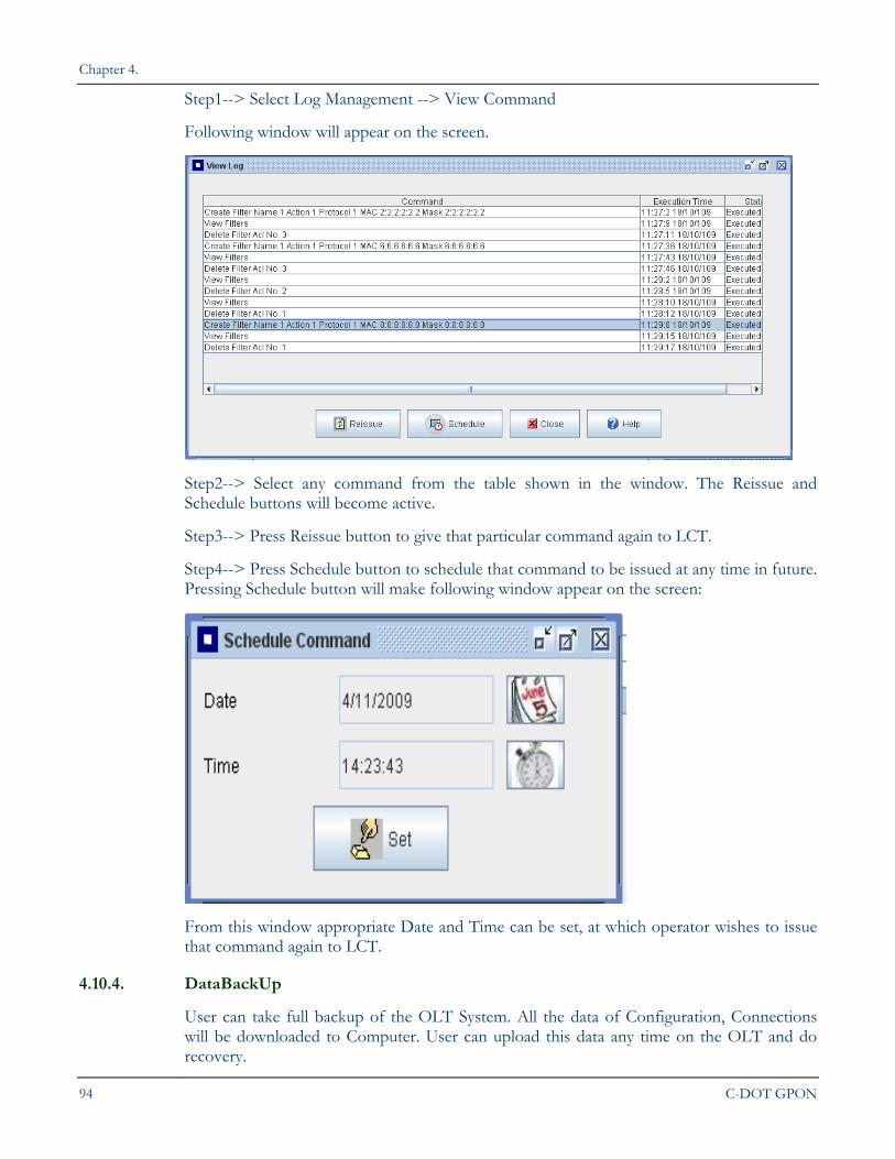
4.10.2. Print on @ LCT
This feature is for debugging purpose specially for Developers. Whenever user wants to direct Prints to Console/File , he can select Modules and Enable Prints ON/OFF for that module. After Enabling Prints ON , the Developer will be able to see prints of his module and debug the feature well.
Step1--> Select Log Management -> Print on @ LCT
Following window will appear
Step2--> Check any acheck box and press "printon" or "print off" button.
4.10.3. View Command
This option is used to view the commands given to the OLT by the user, their execution time and status. To access this option:
Chapter 4.
94 C-DOT GPON
Step1--> Select Log Management --> View Command
Following window will appear on the screen.
Step2--> Select any command from the table shown in the window. The Reissue and Schedule buttons will become active.
Step3--> Press Reissue button to give that particular command again to LCT.
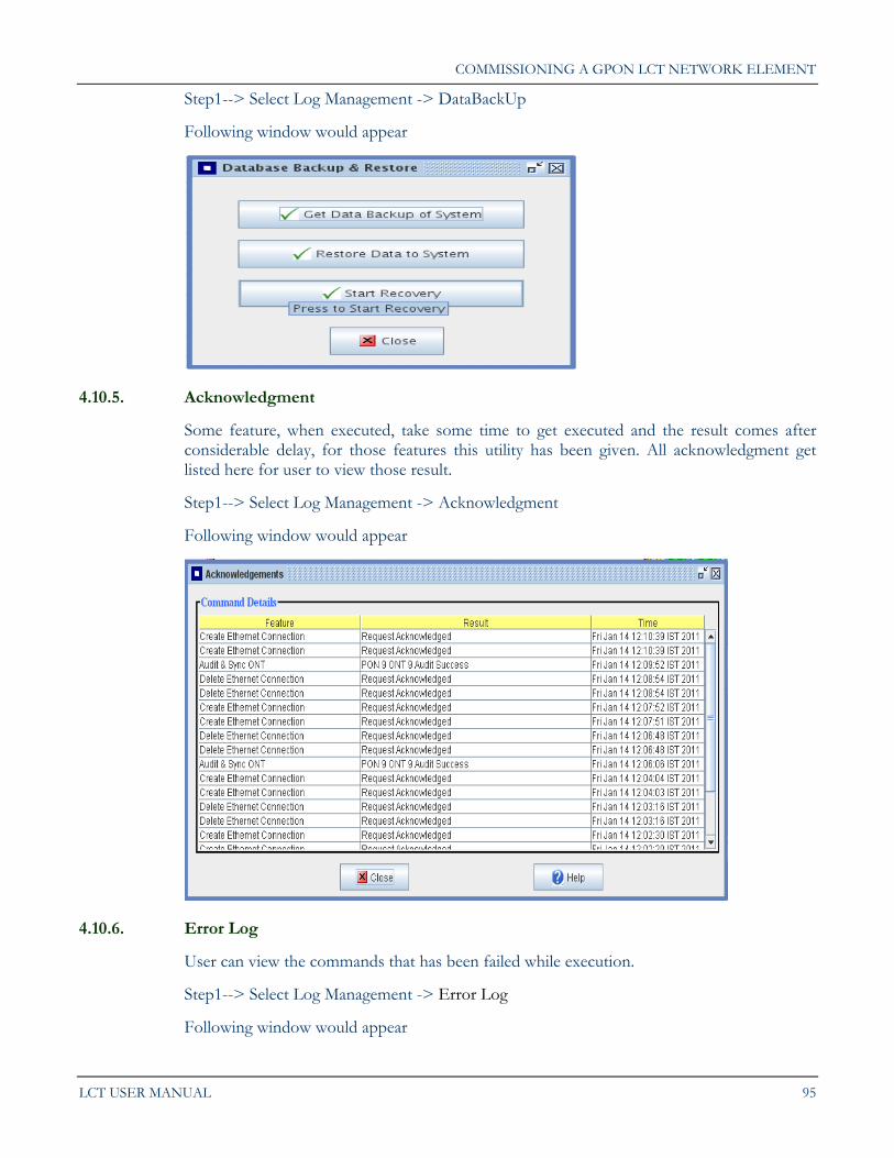
Step4--> Press Schedule button to schedule that command to be issued at any time in future. Pressing Schedule button will make following window appear on the screen:
From this window appropriate Date and Time can be set, at which operator wishes to issue that command again to LCT.
4.10.4. DataBackUp
User can take full backup of the OLT System. All the data of Configuration, Connections will be downloaded to Computer. User can upload this data any time on the OLT and do recovery.
COMMISSIONING A GPON LCT NETWORK ELEMENT
LCT USER MANUAL 95
Step1--> Select Log Management -> DataBackUp
Following window would appear
4.10.5. Acknowledgment
Some feature, when executed, take some time to get executed and the result comes after considerable delay, for those features this utility has been given. All acknowledgment get listed here for user to view those result.
Step1--> Select Log Management -> Acknowledgment
Following window would appear
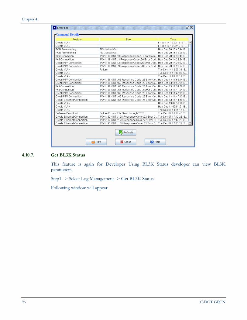
4.10.6. Error Log
User can view the commands that has been failed while execution.
Step1--> Select Log Management -> Error Log
Following window would appear
Chapter 4.
96 C-DOT GPON
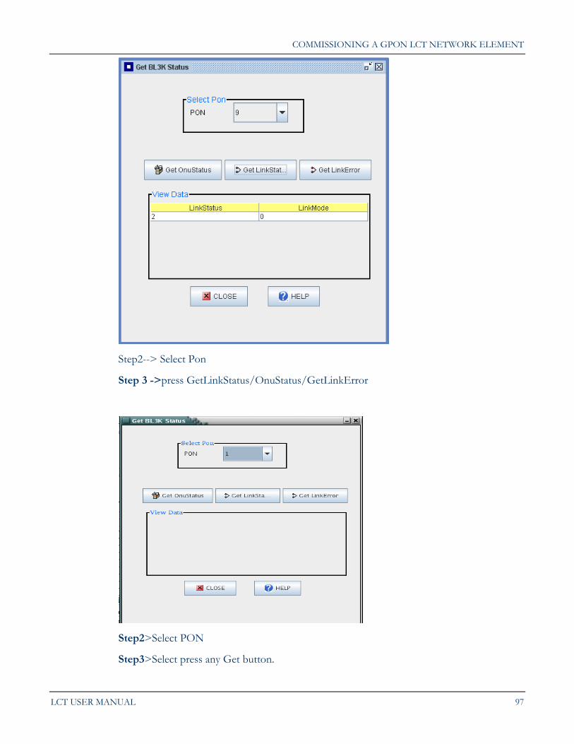
4.10.7. Get BL3K Status
This feature is again for Developer Using BL3K Status developer can view BL3K parameters.
Step1--> Select Log Management -> Get BL3K Status
Following window will appear
COMMISSIONING A GPON LCT NETWORK ELEMENT
LCT USER MANUAL 97
Step2--> Select Pon
Step 3 ->press GetLinkStatus/OnuStatus/GetLinkError
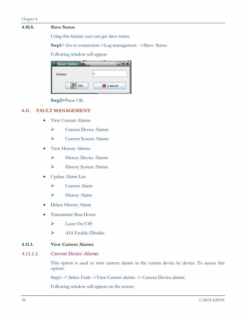
Step2>Select PON
Step3>Select press any Get button.
Chapter 4.
98 C-DOT GPON
4.10.8. Slave Status
Using this feature user can get slave status
Step1> Go to connection->Log management ->Slave Status
Following window will appear
Step2>Press OK
4.11. FAULT MANAGEMENT
View Current Alarms
Current Device Alarms
Current System Alarms
View History Alarms
History Device Alarms
History System Alarms
Update Alarm List
Current Alarm
History Alarm
Delete History Alarm
Transmitter Shut Down
Laser On/Off
ALS Enable/Disable
4.11.1. View Current Alarms
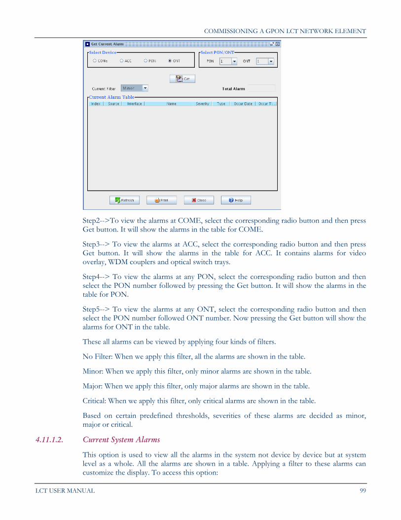
4.11.1.1. Current Device Alarms
This option is used to view current alarms in the system device by device. To access this option:
Step1--> Select Fault-->View Current alarms -> Current Device alarms.
Following window will appear on the screen.
COMMISSIONING A GPON LCT NETWORK ELEMENT
LCT USER MANUAL 99
Step2-->To view the alarms at COME, select the corresponding radio button and then press Get button. It will show the alarms in the table for COME.
Step3--> To view the alarms at ACC, select the corresponding radio button and then press Get button. It will show the alarms in the table for ACC. It contains alarms for video overlay, WDM couplers and optical switch trays.
Step4--> To view the alarms at any PON, select the corresponding radio button and then select the PON number followed by pressing the Get button. It will show the alarms in the table for PON.
Step5--> To view the alarms at any ONT, select the corresponding radio button and then select the PON number followed ONT number. Now pressing the Get button will show the alarms for ONT in the table.
These all alarms can be viewed by applying four kinds of filters.
No Filter: When we apply this filter, all the alarms are shown in the table.
Minor: When we apply this filter, only minor alarms are shown in the table.
Major: When we apply this filter, only major alarms are shown in the table.
Critical: When we apply this filter, only critical alarms are shown in the table.
Based on certain predefined thresholds, severities of these alarms are decided as minor, major or critical.
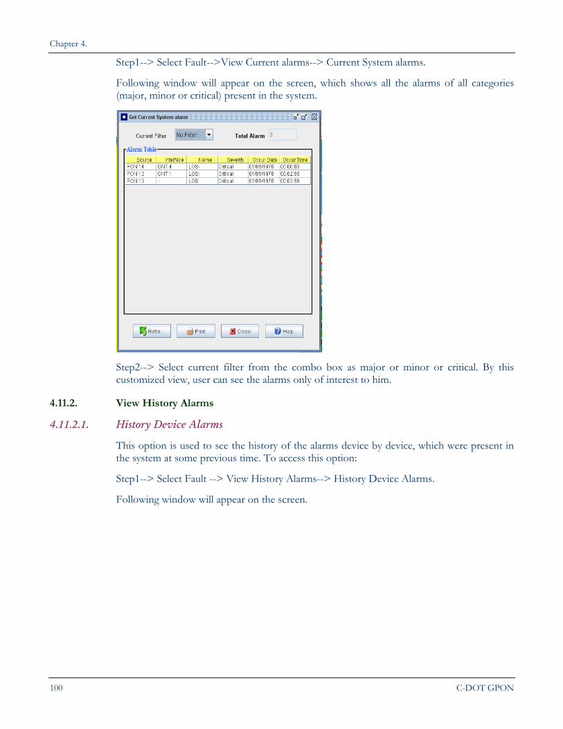
4.11.1.2. Current System Alarms
This option is used to view all the alarms in the system not device by device but at system level as a whole. All the alarms are shown in a table. Applying a filter to these alarms can customize the display. To access this option:
Chapter 4.
100 C-DOT GPON
Step1--> Select Fault-->View Current alarms--> Current System alarms.
Following window will appear on the screen, which shows all the alarms of all categories (major, minor or critical) present in the system.
Step2--> Select current filter from the combo box as major or minor or critical. By this customized view, user can see the alarms only of interest to him.
4.11.2. View History Alarms
4.11.2.1. History Device Alarms
This option is used to see the history of the alarms device by device, which were present in the system at some previous time. To access this option:
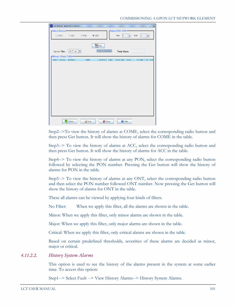
Step1--> Select Fault --> View History Alarms--> History Device Alarms.
Following window will appear on the screen.
COMMISSIONING A GPON LCT NETWORK ELEMENT
LCT USER MANUAL 101
Step2-->To view the history of alarms at COME, select the corresponding radio button and then press Get button. It will show the history of alarms for COME in the table.
Step3--> To view the history of alarms at ACC, select the corresponding radio button and then press Get button. It will show the history of alarms for ACC in the table.
Step4--> To view the history of alarms at any PON, select the corresponding radio button followed by selecting the PON number. Pressing the Get button will show the history of alarms for PON in the table.
Step5--> To view the history of alarms at any ONT, select the corresponding radio button and then select the PON number followed ONT number. Now pressing the Get button will show the history of alarms for ONT in the table.
These all alarms can be viewed by applying four kinds of filters.
No Filter: When we apply this filter, all the alarms are shown in the table.
Minor: When we apply this filter, only minor alarms are shown in the table.
Major: When we apply this filter, only major alarms are shown in the table.
Critical: When we apply this filter, only critical alarms are shown in the table.
Based on certain predefined thresholds, severities of these alarms are decided as minor, major or critical.
4.11.2.2. History System Alarms
This option is used to see the history of the alarms present in the system at some earlier time. To access this option:
Step1--> Select Fault --> View History Alarms--> History System Alarms.

Chapter 4.
102 C-DOT GPON
Following window will appear on the screen, which shows all the alarms of all categories (major, minor or critical in the system
Step2--> Select current filter from the combo box as major or minor or critical. By this customized view, user can see the alarms only of interest to him
4.11.3. Update Alarm List
4.11.3.1. Current Alarm
This option is used to update the alarms present in the system. To access this option:
Step1--> Select Fault --> Update Alarm List--> Current Alarms.
The alarms present in the system currently will be automatically updated.
4.11.3.2. History Alarm
This option is used to update the past alarms present in the system. To access this option:
Step1--> Select Fault --> Update Alarm List--> History Alarms.
The alarms present in the system currently will be automatically updated.
4.11.4. Delete History Alarm
Operator can delete the history alarm list of system using this command.
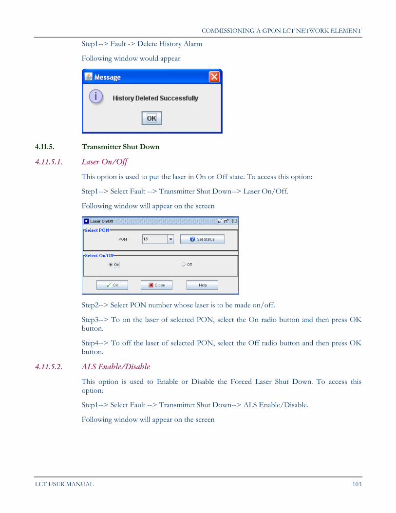
COMMISSIONING A GPON LCT NETWORK ELEMENT
LCT USER MANUAL 103
Step1--> Fault -> Delete History Alarm
Following window would appear
4.11.5. Transmitter Shut Down
4.11.5.1. Laser On/Off
This option is used to put the laser in On or Off state. To access this option:
Step1--> Select Fault --> Transmitter Shut Down--> Laser On/Off.
Following window will appear on the screen
Step2--> Select PON number whose laser is to be made on/off.
Step3--> To on the laser of selected PON, select the On radio button and then press OK button.
Step4--> To off the laser of selected PON, select the Off radio button and then press OK button.
4.11.5.2. ALS Enable/Disable
This option is used to Enable or Disable the Forced Laser Shut Down. To access this option:
Step1--> Select Fault --> Transmitter Shut Down--> ALS Enable/Disable.
Following window will appear on the screen
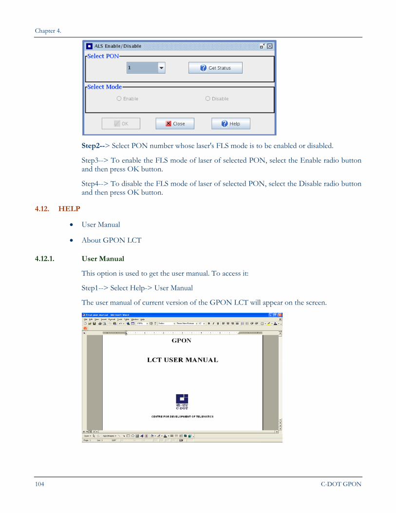
Chapter 4.
104 C-DOT GPON
Step2--> Select PON number whose laser's FLS mode is to be enabled or disabled.
Step3--> To enable the FLS mode of laser of selected PON, select the Enable radio button and then press OK button.
Step4--> To disable the FLS mode of laser of selected PON, select the Disable radio button and then press OK button.
4.12. HELP
User Manual
About GPON LCT
4.12.1. User Manual
This option is used to get the user manual. To access it:
Step1--> Select Help-> User Manual
The user manual of current version of the GPON LCT will appear on the screen.
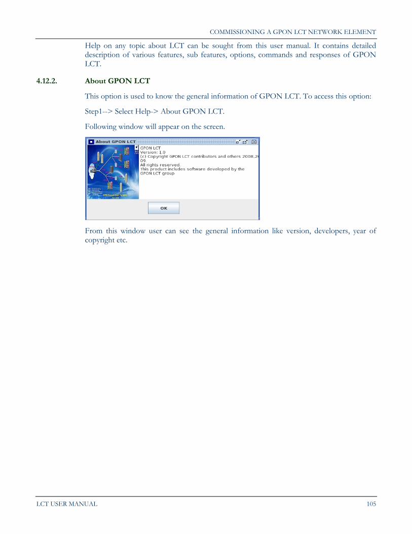
COMMISSIONING A GPON LCT NETWORK ELEMENT
LCT USER MANUAL 105
Help on any topic about LCT can be sought from this user manual. It contains detailed description of various features, sub features, options, commands and responses of GPON LCT.
4.12.2. About GPON LCT
This option is used to know the general information of GPON LCT. To access this option:
Step1--> Select Help-> About GPON LCT.
Following window will appear on the screen.
From this window user can see the general information like version, developers, year of copyright etc.