Embed Size (px)
Citation preview
UCRL-TR-225467
LCLS XTOD Tunnel VacuumTransport System (XVTS) FinalDesign Report
S. Shen
October 23, 2006
Disclaimer
This document was prepared as an account of work sponsored by an agency of the United States Government. Neither the United States Government nor the University of California nor any of their employees, makes any warranty, express or implied, or assumes any legal liability or responsibility for the accuracy, completeness, or usefulness of any information, apparatus, product, or process disclosed, or represents that its use would not infringe privately owned rights. Reference herein to any specific commercial product, process, or service by trade name, trademark, manufacturer, or otherwise, does not necessarily constitute or imply its endorsement, recommendation, or favoring by the United States Government or the University of California. The views and opinions of authors expressed herein do not necessarily state or reflect those of the United States Government or the University of California, and shall not be used for advertising or product endorsement purposes.
This work was performed under the auspices of the U.S. Department of Energy by University of California, Lawrence Livermore National Laboratory under Contract W-7405-Eng-48.
1
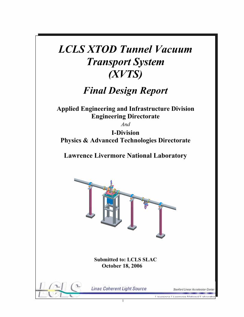
LCLS XTOD Tunnel VacuumTransport System
(XVTS) Final Design Report
Applied Engineering and Infrastructure DivisionEngineering Directorate
AndI-Division
Physics & Advanced Technologies Directorate
Lawrence Livermore National Laboratory
Submitted to: LCLS SLAC October 18, 2006
2
Disclaimer
This document was prepared as an account of work sponsored by an agency of the United States Government. Neither the United States Government nor the University of California nor any of their employees, makes any warranty, express or implied, or assumes any legal liability or responsibility for the accuracy, completeness, or usefulness of any information, apparatus, product, or process disclosed, or represents that its use would not infringe privately owned rights. Reference herein to any specific commercial product, process, or service by trade name, trademark, manufacturer, or otherwise, does not necessarily constitute or imply its endorsement, recommendation, or favoring by the United States Government or the University of California. The views and opinions of authors expressed herein do not necessarily state or reflect those of the United States Government or the University of California, and shall not be used for advertising or product endorsement purposes.
This work was performed under the auspices of the U.S. Department of Energy by University of California, Lawrence Livermore National Laboratory under Contract W-7405-Eng-48.Work supported in part by the DOE Contract DE-AC02-76SF00515. This work was performed in support of the LCLS project at SLAC.
3
TABLE OF CONTENTS1 INTRODUCTION........................................................................................................... 5
1.1 GENERAL DESCRIPTION ............................................................................................................................ 51.2 DELIVERABLES......................................................................................................................................... 71.3 GENERAL SYSTEM REQUIREMENTS ........................................................................................................... 91.4 CLOSURE OF PDR CONCERN ISSUES .......................................................................................................... 91.5 VACUUM SYSTEM DESIGN APPROACH AND DESIGN LAYOUT ....................................................................10
2 PERFORMANCE SPECIFICATIONS........................................................................ 122.1 SYSTEM REQUIREMENTS..........................................................................................................................122.2 BEAM CLEARANCE & BEAM TUBE SIZE - BEAM AND MIRROR POINTING SIMULATIONS..............................132.4 ENGINEERING SPECIFICATIONS.................................................................................................................21
3 VACUUM SYSTEM DESIGN AND ANALYSIS ........................................................ 223.1 GENERAL DESCRIPTION ...........................................................................................................................223.2 SYSTEM ANALYSIS ..................................................................................................................................24
3.2.1 Numerical Vacuum Model...........................................................................................................243.2.2 Outgassing Rate Assumptions......................................................................................................263.2.3 Pump Models..............................................................................................................................26
3.3 FAILURE ANALYSIS .................................................................................................................................323.4 SYSTEM ROBUSTNESS TO HIGHER OUTGASSING RATES ...............................................................................34
4 MECHANICAL DESIGN............................................................................................. 354.1 INTRODUCTION........................................................................................................................................354.2 GENERAL DESCRIPTION ...........................................................................................................................354.3 STRUCTURAL ANALYSIS SUMMARY .........................................................................................................384.4 SEISMIC ANALYSES – ANCHORING ...........................................................................................................434.5 INSTALLATION AND ALIGNMENT ..............................................................................................................44
5 INSTRUMENTATION AND CONTROL ................................................................... 455.1 INTRODUCTION........................................................................................................................................45
5.1.1 Naming Convention.....................................................................................................................455.2 VACUUM CONTROL SYSTEM ARCHITECTURE............................................................................................48
5.2.1 Mechanical Vacuum Devices.......................................................................................................485.2.2 Instrumentation...........................................................................................................................495.2.3 Controllers .................................................................................................................................495.2.4 Vacuum Racks/Cabling ...............................................................................................................49
5.3 PROGRAMMABLE LOGIC CONTROLLER (PLC)...........................................................................................505.3.1 Allen-Bradley PLC......................................................................................................................505.3.2 Uninterruptible Power Supply (UPS) for PLC .............................................................................51
5.4 EXPERIMENTAL PHYSICS INDUSTRIAL CONTROL SYSTEM (EPICS) INPUT OUTPUT CONTROLLER (IOC)......515.4.1 Ether-IP Driver...........................................................................................................................515.4.2 RS-232 Serial Connections..........................................................................................................51
5.5 OTHER EPICS HARDWARE AND SOFTWARE .............................................................................................515.6 FAILURE MODE ANALYSIS .......................................................................................................................53
6 ENVIRONMENTAL, SAFETY, AND HEALTH........................................................ 616.1 DESIGN DETAILS .....................................................................................................................................616.2 ES&H POLICY.........................................................................................................................................616.3 DESIGN DETAILS & POTENTIAL HAZARDS ................................................................................................63
7 PROCUREMENT / FABRICATION & INSTALLATION PLAN............................. 647.1 HARDWARE COSTS/PROCUREMENT PLAN/QA PLAN .................................................................................647.2 FABRICATION, INSTALLATION AND TESTING PLAN ....................................................................................64
4
7.3 FACILITY INTERFACE ...............................................................................................................................68
8 PROJECT SCHEDULE................................................................................................ 709 SUMMARY ................................................................................................................... 7110 REFERENCES.............................................................................................................. 7211 APPENDIX.................................................................................................................... 73
11.A XVTS PDR REVIEW COMMITTEE REPORT .............................................................................................7311.B. INSTALLATION AND ALIGNMENT PROCEDURES......................................................................................7811.C. CONTROLS DOCUMENTATION................................................................................................................8011.D. LLNL IWS 12920 ................................................................................................................................8111.E. XVTS MECHANICAL ENGINEERING DRAWINGS .....................................................................................9411.F XVTS ELECTRICAL ENGINEERING CONTROL DRAWINGS .........................................................................96
5
1 Introduction
The design of the X-Ray Vacuum Transport System (XVTS) for the Linac Coherent Light Source(LCLS) X-ray Transport, Optics and Diagnostics (XTOD) system has been analyzed and configured by the Lawrence Livermore National Laboratory’s New Technologies Engineering Division (NTED) as requested by the SLAC/LCLS program. A preliminary design review was held on 11/14/05 [1][2]. This FDR (Final Design Report) presents system configuration, detailed analyses and selection of the mechanical and electrical components for the XTOD tunnel section, as well as the response to all issues raised in the review committee report. Also included are the plans for procurement, mechanical integration, schedule and the cost estimates.
It should be noticed that, after the XVTS PDR, LCLS management has decided to lower the number of beamlines from three to one, and shorten the tunnel length from 212 m to 184 m. [3][4]
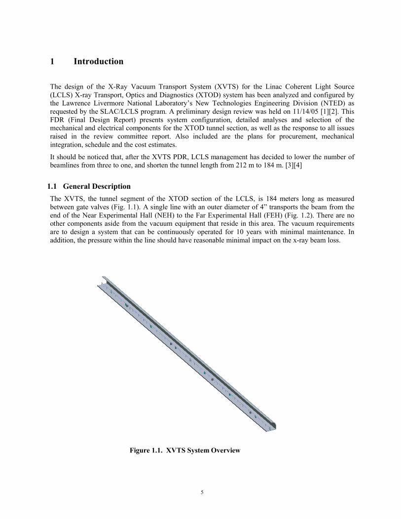
1.1 General DescriptionThe XVTS, the tunnel segment of the XTOD section of the LCLS, is 184 meters long as measured between gate valves (Fig. 1.1). A single line with an outer diameter of 4” transports the beam from the end of the Near Experimental Hall (NEH) to the Far Experimental Hall (FEH) (Fig. 1.2). There are no other components aside from the vacuum equipment that reside in this area. The vacuum requirements are to design a system that can be continuously operated for 10 years with minimal maintenance. In addition, the pressure within the line should have reasonable minimal impact on the x-ray beam loss.
Figure 1.1. XVTS System Overview

6
Figure 1.2. XVTS System View Close-up
The final design goals of the XVTS system call for the following system features:
• The tunnel vacuum system will have the capability of being isolated with neighboring systems by gate valves. While the vacuum pumps may be operated in a manual mode (via their own controller), for such things as leak checking and vacuum conditioning, one local controller will supervise and operate the vacuum systems on a modular basis.
• There will be one central gate valve to separate the 184-meter line into 2 sections to facilitate repairs if necessary.
• A turbo/roughing pump cart will condition each section and serve as transitional pumping to a suitable base pressure (10-6 Torr range) in order to allow for ion pump operation. Ion pumps will provide for the steady-state vacuum pumping.
• A low vacuum and a high vacuum gauge will be needed on each module for system operation, vacuum monitoring and safety interlocks. The line is equipped with an RGA head.
• Nitrogen purge lines with pressure regulators and relief valves or burst disc will allow the line to be safely back-filled with dry nitrogen gas during maintenance periods.
• The valves, pumps and gauges are controlled by ladder logic executed on a commercial Programmable Logic Controller (PLCs) such as those manufactured by Allen Bradley. A high-level Experimental Physics and Industrial Control System (EPICS) linked to the LCLS global control software provides overall control and monitoring.
7
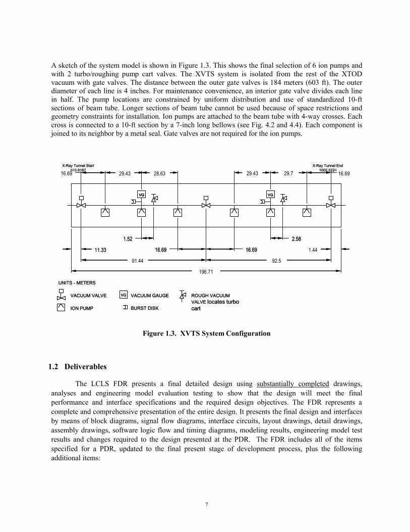
A sketch of the system model is shown in Figure 1.3. This shows the final selection of 6 ion pumps and with 2 turbo/roughing pump cart valves. The XVTS system is isolated from the rest of the XTOD vacuum with gate valves. The distance between the outer gate valves is 184 meters (603 ft). The outer diameter of each line is 4 inches. For maintenance convenience, an interior gate valve divides each line in half. The pump locations are constrained by uniform distribution and use of standardized 10-ft sections of beam tube. Longer sections of beam tube cannot be used because of space restrictions and geometry constraints for installation. Ion pumps are attached to the beam tube with 4-way crosses. Each cross is connected to a 10-ft section by a 7-inch long bellows (see Fig. 4.2 and 4.4). Each component is joined to its neighbor by a metal seal. Gate valves are not required for the ion pumps.
Figure 1.3. XVTS System Configuration
1.2 Deliverables
The LCLS FDR presents a final detailed design using substantially completed drawings, analyses and engineering model evaluation testing to show that the design will meet the final performance and interface specifications and the required design objectives. The FDR represents a complete and comprehensive presentation of the entire design. It presents the final design and interfaces by means of block diagrams, signal flow diagrams, interface circuits, layout drawings, detail drawings, assembly drawings, software logic flow and timing diagrams, modeling results, engineering model test results and changes required to the design presented at the PDR. The FDR includes all of the items specified for a PDR, updated to the final present stage of development process, plus the following additional items:
16.6916.69 29.43
91.44
11.33
92.5
196.71
VACUUM VALVE
ION PUMP
28.63
16.69 16.69
29.43 29.7
1.44
1.52 2.58
ROUGH VACUUM VALVE locates turbo cart
VG
VACUUM GAUGE
VG
VG
BURST DISK
UNITS - METERS
X-Ray Tunnel Start 805.8167
X-Ray Tunnel End 1002.5224
16.6916.69 29.43
91.44
11.33
92.5
196.71
VACUUM VALVE
ION PUMP
28.63
16.69 16.69
29.43 29.7
1.44
1.52 2.58
ROUGH VACUUM VALVE locates turbo cart
VGVG
VACUUM GAUGE
VGVG
VGVG
BURST DISK
UNITS - METERS
X-Ray Tunnel Start 805.8167
X-Ray Tunnel End 1002.5224

8
9
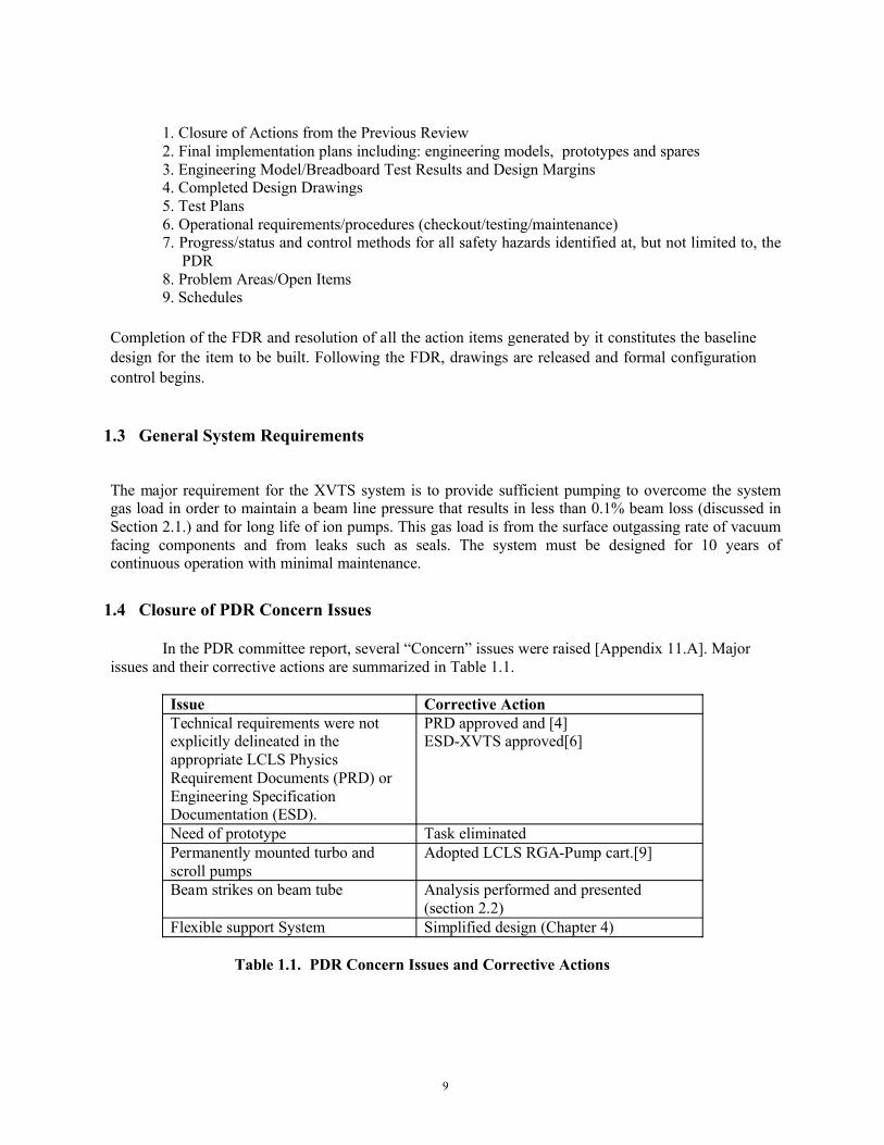
1. Closure of Actions from the Previous Review 2. Final implementation plans including: engineering models, prototypes and spares 3. Engineering Model/Breadboard Test Results and Design Margins 4. Completed Design Drawings 5. Test Plans 6. Operational requirements/procedures (checkout/testing/maintenance) 7. Progress/status and control methods for all safety hazards identified at, but not limited to, the
PDR 8. Problem Areas/Open Items 9. Schedules
Completion of the FDR and resolution of all the action items generated by it constitutes the baseline design for the item to be built. Following the FDR, drawings are released and formal configuration control begins.
1.3 General System Requirements
The major requirement for the XVTS system is to provide sufficient pumping to overcome the system gas load in order to maintain a beam line pressure that results in less than 0.1% beam loss (discussed in Section 2.1.) and for long life of ion pumps. This gas load is from the surface outgassing rate of vacuum facing components and from leaks such as seals. The system must be designed for 10 years of continuous operation with minimal maintenance.
1.4 Closure of PDR Concern Issues
In the PDR committee report, several “Concern” issues were raised [Appendix 11.A]. Major issues and their corrective actions are summarized in Table 1.1.
Issue Corrective ActionTechnical requirements were not explicitly delineated in the appropriate LCLS Physics Requirement Documents (PRD) or Engineering Specification Documentation (ESD).
PRD approved and [4]ESD-XVTS approved[6]
Need of prototype Task eliminatedPermanently mounted turbo and scroll pumps
Adopted LCLS RGA-Pump cart.[9]
Beam strikes on beam tube Analysis performed and presented (section 2.2)
Flexible support System Simplified design (Chapter 4) Table 1.1. PDR Concern Issues and Corrective Actions

10
1.5 Vacuum System Design Approach and Design Layout
In developing the design for the XVTS pumping system, a conscious effort was made to build in robustness that will guarantee adequate pumping over a 10 year period of continuous operation. This was accomplished by specifying reliable components in the system to safeguard against possible failures. In addition, we installed redundancy to counteract unforeseen operating conditions or vacuum failures in the system. The design presented in this report is based on the experience with accelerator projects such as APT/RFQ, APT/LEDA/DTL-CCL, SNS/DTL-CCL, DARHT II, and SLAC B-Factory. Relevant vacuum systems of major accelerator facilities are also referenced. The major features of the design are summarized in the Table 1.2.
Issue Design Approach Feature DescriptionsHigh-Vacuum Pumping
Ion Pump Based on wide operation experience in accelerator applications.Selected for its reliability and ease of operationTime between maintenance of > 8 yrs
Instrumentation-Mid-vacuum
Convection Enhanced Pirani
Based on favorable operation experience.
Instrumentation-High-vacuum
Stabil-Ion orCold-Cathode
Based on favorable operation experience.
Instrumentation-High-vacuum
RGA Based on favorable operation experience.
Control Allen-Bradley ControlLogix PLC
Consistent with those used elsewhere in the LCLS facility.
Table 1.2. Design Features of XVTS System
Current XVTS system consists of single line that is 4 inches in outer diameter and 184 meters long. The vacuum pumps are connected to the bottom side of the beam line. The vacuum pump spacing along each line is determined by detailed vacuum models (presented in Chapter 3 of this report). A cart with a turbo-roughing system is proposed for conditioning the line, while ion pumps are recommended for continuous operation. Isolation valves are positioned at the ends, as well as with one in the middle of the line (as seen in Fig. 1.3) bringing a total of 3 isolation valves.
Each section of each beamline is equipped with two cold cathode gauges and each beam line will have one RGA head and pressure relief device. These instruments provide a means to monitor system pressure and gas constituents during the conditioning and operational phases. This is important for correct vacuum pump sequencing (transition from turbo pump to ion pump), monitoring vacuum system performance, and diagnosing manufacturing defects and vacuum leaks. Each isolatable section will be equipped with a valve for connecting to a source of dry nitrogen gas, required for venting the module during a maintenance operation.
The type and size of the pumps are chosen to provide a) a beam line pressure below the specification, with redundancy in case of ion pump failure that does not require immediate shut down of the system; b) reliable pumping during system conditioning; and c) minimal cost for the lowest reasonable pressure.
11
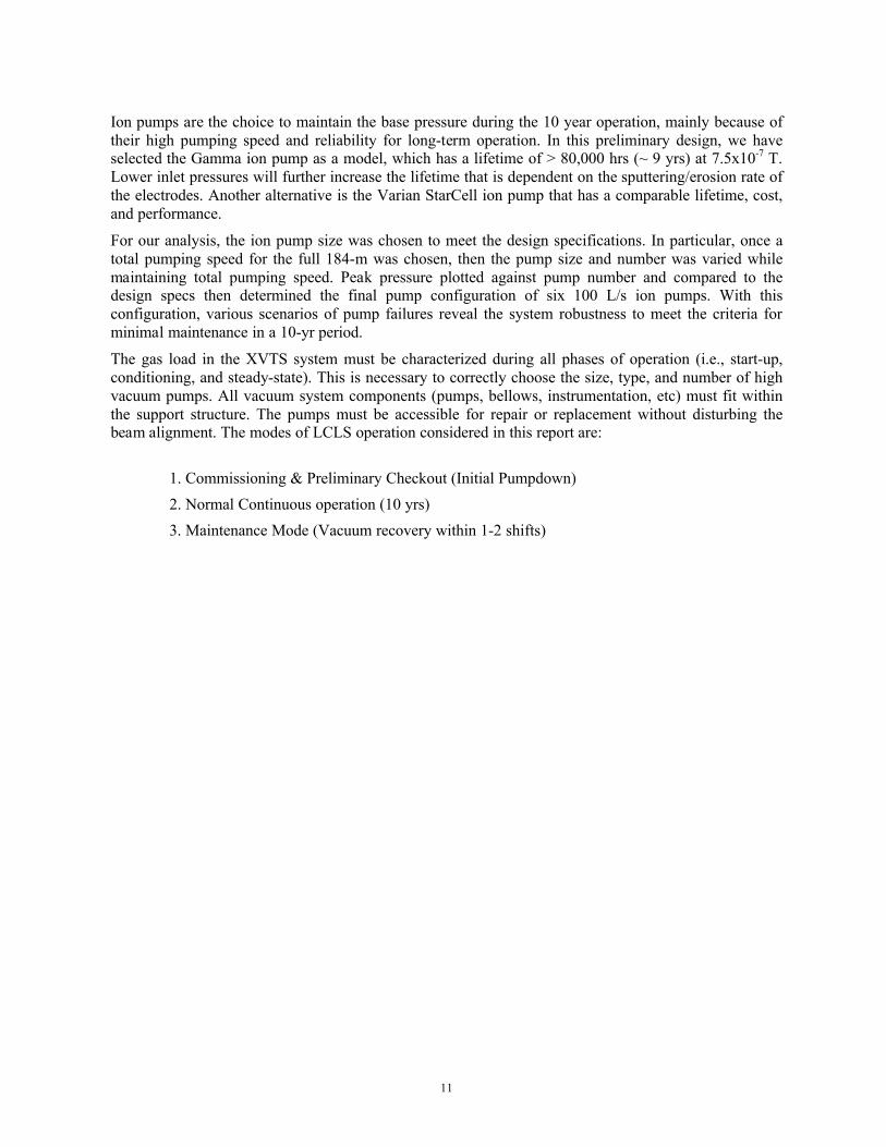
Ion pumps are the choice to maintain the base pressure during the 10 year operation, mainly because of their high pumping speed and reliability for long-term operation. In this preliminary design, we have selected the Gamma ion pump as a model, which has a lifetime of > 80,000 hrs (~ 9 yrs) at 7.5x10⁻⁷ T. Lower inlet pressures will further increase the lifetime that is dependent on the sputtering/erosion rate of the electrodes. Another alternative is the Varian StarCell ion pump that has a comparable lifetime, cost,and performance.
For our analysis, the ion pump size was chosen to meet the design specifications. In particular, once a total pumping speed for the full 184-m was chosen, then the pump size and number was varied while maintaining total pumping speed. Peak pressure plotted against pump number and compared to the design specs then determined the final pump configuration of six 100 L/s ion pumps. With this configuration, various scenarios of pump failures reveal the system robustness to meet the criteria forminimal maintenance in a 10-yr period.
The gas load in the XVTS system must be characterized during all phases of operation (i.e., start-up, conditioning, and steady-state). This is necessary to correctly choose the size, type, and number of high vacuum pumps. All vacuum system components (pumps, bellows, instrumentation, etc) must fit within the support structure. The pumps must be accessible for repair or replacement without disturbing the beam alignment. The modes of LCLS operation considered in this report are:
1. Commissioning & Preliminary Checkout (Initial Pumpdown)2. Normal Continuous operation (10 yrs)3. Maintenance Mode (Vacuum recovery within 1-2 shifts)

12
2 Performance Specifications
All documents relevant to the Physics Requirements for XVTS system are listed in the following table (Table 2.1).
Reference No.
Document No. Issued Date
Description
[5] LCLS PRD # 1.5-001 5/14/04 Requirements for the LCLS X-Ray Transport and Diagnostics
[6] LCLS ESD # 1.1-302 7/26/05 LCLS Mechanical Vacuum Specifications
[7] LCLS PRD # 1.5-002 2/15/06 Physics Requirements for the XTOD Mechanical-Vacuum Systems
[8] 11/16/05 LCLS Conventional Facility Title II – 60% Submitted Drawings
[9] SLAC-I-007-12004-001 R1
4/17/03 SLAC Vacuum Department Guidelines for Vacuum Systems
Table 2.1. Lists of Reference Documents
“Physics Requirements for the LCLS X-Ray Transport and Diagnostics” – Beam Transport Requirements states that:
“The vacuum flight path must be sized to exclude the possibility of being struck by the x-ray beam. The average pressure throughout the system should be less than 10-5 Torr. In addition, the pressure at the ion pumps must be low enough to ensure long pump life (> 10 years). Vacuum components that are highly susceptible to radiation damage, such as elastomer o-rings, are discouraged. In general, SLAC standard procedures for cleaning and handling of UHV components must be followed.”
2.1 System Requirements
The primary requirement for the XVTS vacuum system is to provide sufficient pumping to overcome the surface outgassing rate of vacuum facing components and seal leaks and maintain a line pressure within the designed value.
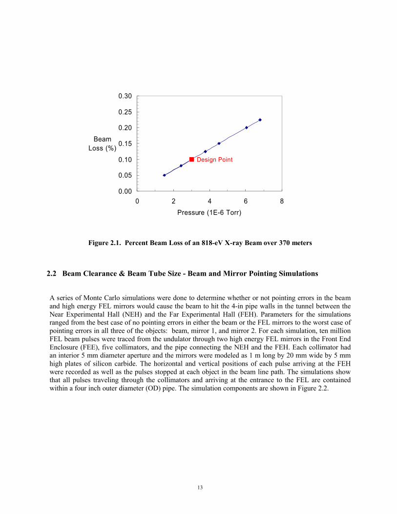
The vacuum requirements are determined by two conditions. First, background neutral pressure should be less than 10-5 Torr to minimize the beam loss. Also, pump port pressure should be low enough that pump lifetime can be at least 10 yrs. The second requirement is actually the most stringent. Figure 2.1 below shows how the beam degrades with pressure when the beam energy is 818 eV. Higher energies (which will be more typical) degrade even less with pressure. Thus, the design pressure is chosen to be 3 x 10⁻⁶ Torr so that the beam loss is below 0.1% during normal operation. If pumps fail, the pressure should be less than 6 x 10⁻⁶ T and operation can continue for up to a year until pumps can be repaired. Detailed failure scenarios are presented later in this report.
13
Design Point
0.00
0.05
0.10
0.15
0.20
0.25
0.30
0 2 4 6 8Pressure (1E-6 Torr)
BeamLoss (%)
Figure 2.1. Percent Beam Loss of an 818-eV X-ray Beam over 370 meters
2.2 Beam Clearance & Beam Tube Size - Beam and Mirror Pointing Simulations
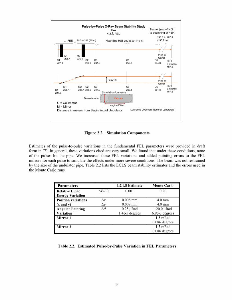
A series of Monte Carlo simulations were done to determine whether or not pointing errors in the beam and high energy FEL mirrors would cause the beam to hit the 4-in pipe walls in the tunnel between the Near Experimental Hall (NEH) and the Far Experimental Hall (FEH). Parameters for the simulations ranged from the best case of no pointing errors in either the beam or the FEL mirrors to the worst case of pointing errors in all three of the objects: beam, mirror 1, and mirror 2. For each simulation, ten million FEL beam pulses were traced from the undulator through two high energy FEL mirrors in the Front End Enclosure (FEE), five collimators, and the pipe connecting the NEH and the FEH. Each collimator had an interior 5 mm diameter aperture and the mirrors were modeled as 1 m long by 20 mm wide by 5 mm high plates of silicon carbide. The horizontal and vertical positions of each pulse arriving at the FEH were recorded as well as the pulses stopped at each object in the beam line path. The simulations show that all pulses traveling through the collimators and arriving at the entrance to the FEL are contained within a four inch outer diameter (OD) pipe. The simulation components are shown in Figure 2.2.
14
Figure 2.2. Simulation Components
Estimates of the pulse-to-pulse variations in the fundamental FEL parameters were provided in draft form in [7]. In general, these variations cited are very small. We found that under these conditions, none of the pulses hit the pipe. We increased these FEL variations and added pointing errors to the FEL mirrors for each pulse to simulate the effects under more severe conditions. The beam was not restrained by the size of the undulator pipe. Table 2.2 lists the LCLS beam stability estimates and the errors used in the Monte Carlo runs.
Parameters LCLS Estimate Monte CarloRelative Linac Energy Variation
ΔE/E0 0.001 0.20
Position variations(x and y)
ΔxΔy
0.008 mm0.008 mm
4.0 mm4.0 mm
Angular Pointing Variation
Δθ 0.25 μRad1.4e-5 degrees
120.0 μRad6.9e-3 degrees
Mirror 1 1.5 mRad0.086 degrees
Mirror 2 1.5 mRad0.086 degrees
Table 2.2. Estimated Pulse-by-Pulse Variation in FEL Parameters
C1227.8
M1228.4
M2236.4 C5
253.5C3241.0
C2238.0
C6264.8
C = CollimatorM = MirrorDistance in meters from Beginning of Undulator
Pulse-by-Pulse X-Ray Beam Stability StudyFor
1.5Å FEL
Lawrence Livermore National Laboratory
Pipe in tunnel
FEH Entrance487.5
C1227.8
M1228.4
M2236.4
C5253.5
C3241.0
C2238.0
C6264.8
Pipe in tunnel
0.024m
242 to 291 (49 m)Near End Hall207 to 242 (35 m)FEE…
FEH Entrance487.5
Tunnel (end of NEH to beginning of FEH)
290.8 to 487.5 (196.7 m)
Diameter=4 m
Length=500 m
Vacuum
Simulation Universe
15
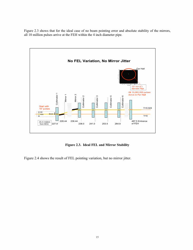
Figure 2.3 shows that for the ideal case of no beam pointing error and absolute stability of the mirrors, all 10 million pulses arrive at the FEH within the 4 inch diameter pipe.
Figure 2.3. Ideal FEL and Mirror Stability
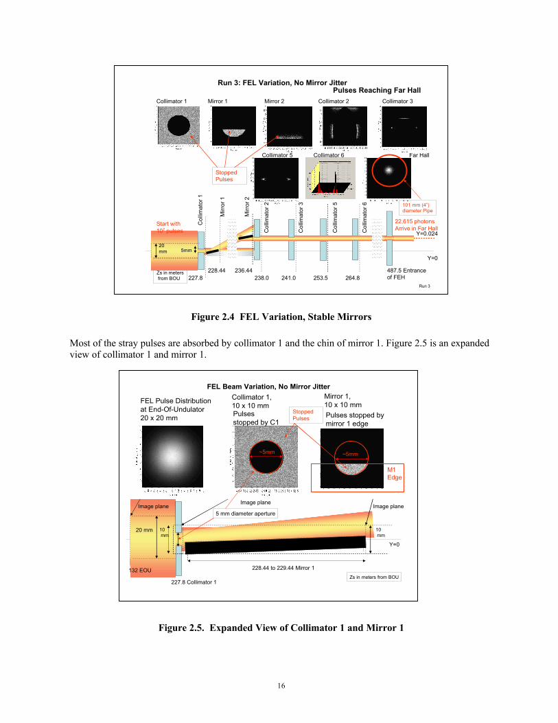
Figure 2.4 shows the result of FEL pointing variation, but no mirror jitter.
Zs in metersfrom BOU
No FEL Variation, No Mirror Jitter
Y=0
236.44238.0227.8
Mirr
or 2
Col
limat
or 2
241.0 253.5 264.8
Col
limat
or 3
Col
limat
or 5
Col
limat
or 6
Y=0.024
487.5 Entrance of FEH
228.44
20 mm 5mm
Mirr
or 1
Col
limat
or 1
Start with107 pulses
All 10,000,000 pulsesArrive in Far Hall
Far Hall
101 mm (4”) diameter Pipe
16
Figure 2.4 FEL Variation, Stable Mirrors
Most of the stray pulses are absorbed by collimator 1 and the chin of mirror 1. Figure 2.5 is an expanded view of collimator 1 and mirror 1.
Figure 2.5. Expanded View of Collimator 1 and Mirror 1
20 mm
5 mm diameter aperture
227.8 Collimator 1Zs in meters from BOU
228.44 to 229.44 Mirror 1
FEL Beam Variation, No Mirror Jitter
10mm
FEL Pulse Distribution at End-Of-Undulator20 x 20 mm
Collimator 1,10 x 10 mm
Image plane
Mirror 1,10 x 10 mm
Image plane
132 EOU
Image plane
10mm
Stopped Pulses Pulses stopped by
mirror 1 edgePulses stopped by C1
M1Edge
~5mm ~5mm
Y=0
Zs in metersfrom BOU
Run 3: FEL Variation, No Mirror Jitter
Collimator 1 Mirror 1
Y=0
Collimator 2
236.44
Mirror 2
238.0227.8
Mirr
or 2
Col
limat
or 2
241.0 253.5 264.8
Col
limat
or 3
Col
limat
or 5
Col
limat
or 6
Y=0.024
Collimator 3
22,615 photonsArrive in Far Hall
Collimator 5 Collimator 6
487.5 Entrance of FEH
228.44
20 mm 5mm
Mirr
or 1
Col
limat
or 1
Start with107 pulses
Stopped Pulses
Pulses Reaching Far Hall
Far Hall
101 mm (4”) diameter Pipe
Run 3

17
For the worst case of pointing errors for the beam and both mirrors, only 12 out of 10 million pulses arrive at the FEH, but even those 12 pulses are within the pipe and none hit the pipe wall. All five collimators are needed to absorb the sprayed pulses.
Figure 2.6. Worst Case: FEL Variation and Mirror Pointing Errors
Figure 2.7 shows the effect of mirror jitter on the position of the FEL in the FEH with ideal FEL pointing.
Zs in metersfrom BOU
Collimator 1 Mirror 1
Y=0
Collimator 2
236.44
Mirror 2
238.0227.8
Mirr
or 2
Col
limat
or 2
241.0 253.5 264.8
Col
limat
or 3
Col
limat
or 5
Col
limat
or 6
Y=0.024
Collimator 3
12 pulsesArrive in Far Hall
Collimator 5 Collimator 6
487.5 Entrance of FEH
228.44
20 mm 5mm
Mirr
or 1
Col
limat
or 1
Start with107 pulses
Stopped Pulses
Far Hall
101 mm (4”) diameter Pipe
FEL Beam Variation, M1 and M2 Jitter

18
Figure 2.7. Effect of Mirror Jitter on the FEL positionFigure 2.8 shows the results from combinations of FEL and mirror pointing errors.
Figure 2.8. Combinations of FEL Variation and Mirror Jitter
To summarize, all FEL pulses arriving at the FEH will be contained in the 4 inch OD pipe if the five collimators are in place to limit the beam angular divergence.
No FEL Variation, Mirror 1 and 2 Jitter
Pulses atEntrance to FEH
No FEL Variation, No Mirror Jitter
10,000,000 pulses 5,705 pulses
101 mm (4”) diameter Pipe
22,615 pulses 370 pulses 12 pulses
Pulses atEntrance to FEH
FEL Variation, M1 No JitterM2 No Jitter
FEL Variation, M1 JitterM2 No Jitter
FEL Variation, M1 JitterM2 Jitter
101 mm (4”) diameter Pipe
19
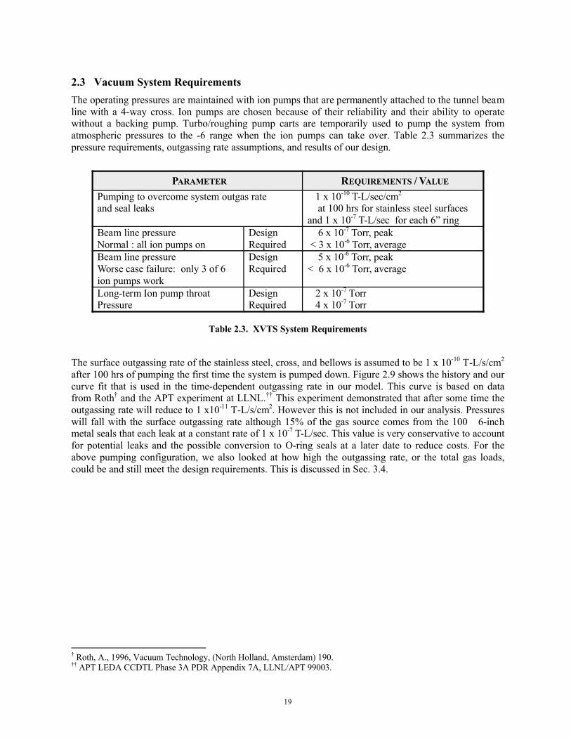
2.3 Vacuum System RequirementsThe operating pressures are maintained with ion pumps that are permanently attached to the tunnel beam line with a 4-way cross. Ion pumps are chosen because of their reliability and their ability to operate without a backing pump. Turbo/roughing pump carts are temporarily used to pump the system from atmospheric pressures to the -6 range when the ion pumps can take over. Table 2.3 summarizes the pressure requirements, outgassing rate assumptions, and results of our design.
PARAMETER REQUIREMENTS / VALUE
Pumping to overcome system outgas rateand seal leaks
1 x 10⁻¹⁰ T-L/sec/cm2
at 100 hrs for stainless steel surfacesand 1 x 10⁻⁷ T-L/sec for each 6” ring
Beam line pressure Normal : all ion pumps on
DesignRequired
6 x 10⁻⁷ Torr, peak< 3 x 10⁻⁶ Torr, average
Beam line pressure Worse case failure: only 3 of 6 ion pumps work
DesignRequired
5 x 10⁻⁶ Torr, peak< 6 x 10⁻⁶ Torr, average
Long-term Ion pump throat Pressure
DesignRequired
2 x 10⁻⁷ Torr4 x 10-7 Torr
Table 2.3. XVTS System Requirements
The surface outgassing rate of the stainless steel, cross, and bellows is assumed to be 1 x 10⁻¹⁰ T-L/s/cm2
after 100 hrs of pumping the first time the system is pumped down. Figure 2.9 shows the history and our curve fit that is used in the time-dependent outgassing rate in our model. This curve is based on data from Roth† and the APT experiment at LLNL.†† This experiment demonstrated that after some time the outgassing rate will reduce to 1 x10-11 T-L/s/cm2. However this is not included in our analysis. Pressures will fall with the surface outgassing rate although 15% of the gas source comes from the 100 6-inch metal seals that each leak at a constant rate of 1 x 10⁻⁷ T-L/sec. This value is very conservative to account for potential leaks and the possible conversion to O-ring seals at a later date to reduce costs. For the above pumping configuration, we also looked at how high the outgassing rate, or the total gas loads, could be and still meet the design requirements. This is discussed in Sec. 3.4.
† Roth, A., 1996, Vacuum Technology, (North Holland, Amsterdam) 190.†† APT LEDA CCDTL Phase 3A PDR Appendix 7A, LLNL/APT 99003.

20
Figure 2.9. Outgassing Rate History for Polished Stainless Steel
10-11
10-10
10-9
10-8
10-7
0.0001 0.001 0.01 0.1 1 10 100 1000
Outgas RateTorr-L/sec/cm2
time (hrs)
6.0 x 10⁻⁸ exp(-1.5 x10⁻³ t) +
2.4 x 10⁻⁸ exp(-2.6 x10⁻⁴ t) + x10-3 t) + x103.0 x 10-9 exp(-6.0 x10⁻⁵ t) +
2.0x 10 -10 exp(-2.0 x10⁻⁵ t) +
1 x 10⁻¹⁰ where t = sec
Roth data
APT data
Fit forced to final rate at 100 hours
21
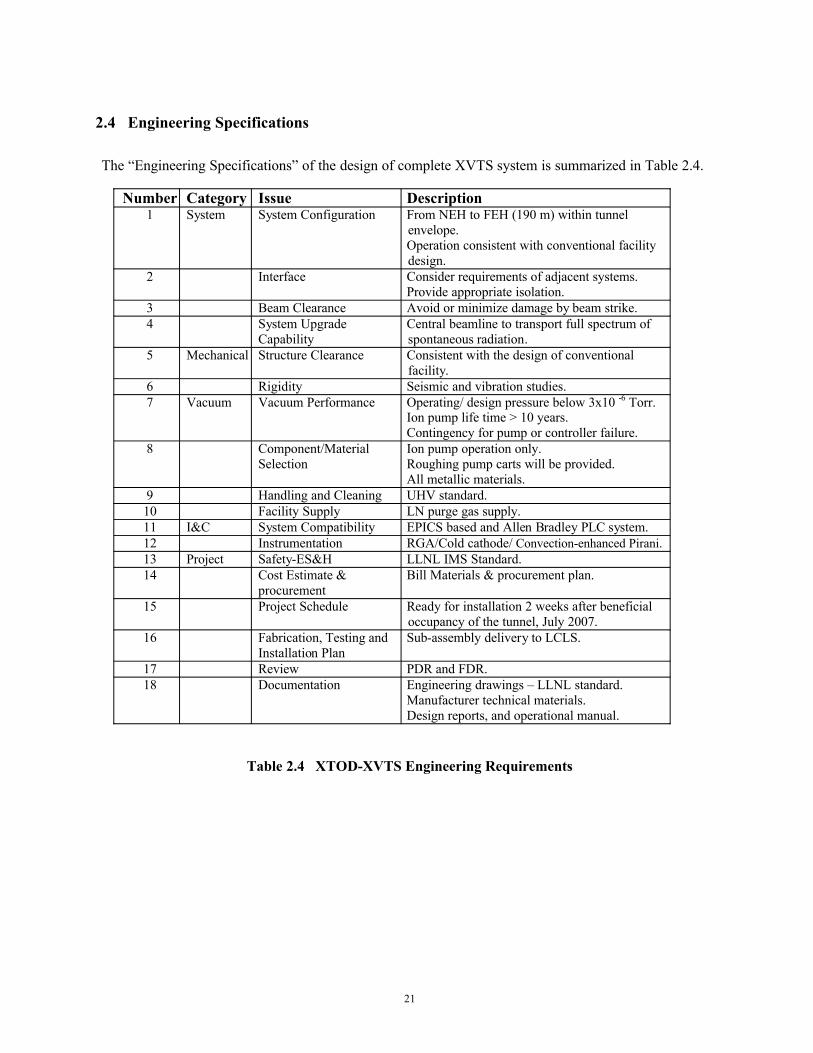
2.4 Engineering Specifications
The “Engineering Specifications” of the design of complete XVTS system is summarized in Table 2.4.
Number Category Issue Description1 System System Configuration From NEH to FEH (190 m) within tunnel
envelope.Operation consistent with conventional facility design.
2 Interface Consider requirements of adjacent systems.Provide appropriate isolation.
3 Beam Clearance Avoid or minimize damage by beam strike.4 System Upgrade
CapabilityCentral beamline to transport full spectrum of spontaneous radiation.
5 Mechanical Structure Clearance Consistent with the design of conventional facility.
6 Rigidity Seismic and vibration studies.7 Vacuum Vacuum Performance Operating/ design pressure below 3x10 -6 Torr.
Ion pump life time > 10 years.Contingency for pump or controller failure.
8 Component/Material Selection
Ion pump operation only.Roughing pump carts will be provided.All metallic materials.
9 Handling and Cleaning UHV standard.10 Facility Supply LN purge gas supply.11 I&C System Compatibility EPICS based and Allen Bradley PLC system.12 Instrumentation RGA/Cold cathode/ Convection-enhanced Pirani.13 Project Safety-ES&H LLNL IMS Standard.14 Cost Estimate &
procurementBill Materials & procurement plan.
15 Project Schedule Ready for installation 2 weeks after beneficial occupancy of the tunnel, July 2007.
16 Fabrication, Testing and Installation Plan
Sub-assembly delivery to LCLS.
17 Review PDR and FDR.18 Documentation Engineering drawings – LLNL standard.
Manufacturer technical materials.Design reports, and operational manual.
Table 2.4 XTOD-XVTS Engineering Requirements

22
3 Vacuum System Design and Analysis
3.1 General Description
A description of components to be evacuated along with our optimized pumping system is provided in Table 3.1. Figure 4.4 shows a 3D drawing of the XVTS pumping configuration for the ion pumps.
XVTS BEAM LINE
184 meters, 4” OD x 0.083” wall tube10 ft sections of stainless steel tube joined with 6” diameter metal seal flangesThree isolation valves: beginning, middle, and end
PUMPING SYSTEM SPECIFICATIONS
One or more turbo/roughing carts with 270 L/s turbo pump and 610 DS scroll pump [9]Six Gamma Titan 100 L/s diode ion pumpsOne bellows and 4-way cross for each ion pump6” diameter metal seal flanges (Conflat Type) between components
DETAILED SYSTEM PARAMETERS
Total stainless steel surface area = 579,718 cm2
Total volume = 1399 LTotal surface outgas rate= 5.85 x10⁻⁵ T-L/sec at 100 hrsTotal gasket leak rate = 1.00 x10⁻⁵ T-L/sec at 100 hrs based on a rate of 1 x 10⁻⁷ Torr-L/sec for 100 6-inch sealsTotal gas loads = 6.85 x10⁻⁵ T-L/sec at 100 hrs Peak pressure after conditioning with 6 ion pumps (normal mode) = 6.4 x 10⁻⁷ TorrPeak pressure after conditioning if 3 ion pumps fail = 5.1 x 10⁻⁶ Torr
Table 3.1. Optimized Vacuum System for 184-m Tunnel Beam Line
The selected scroll-turbo pump cart [10] is illustrated in Fig. 3.1 and 3.2.

23
Figure 3.1. LCLS pump Cart System
Figure 3.2. LCLS Pump Cart System View 2

24
3.2 System Analysis
3.2.1 Numerical Vacuum ModelOur numerical model of the vacuum system analyzes the gas load balance for the XTOD tunnel beam line. The length is assumed to be 184 meters as determined by the convenient location of gate valves. The beam tube is composed of 10-ft long sections. Restrictions in the tunnel determined this section length for assembly.
To solve the gas load matrix for each pumping system, the beam tube needs to be subdivided into discrete sections or sub-volumes. These sub-volumes are connected to each other through effective conductances. We have benchmarked our simple model with the theory of a single pump that evacuates a long beam tube. This theory predicts that
p(x) = q B (L/S + x/C – x2 / (2CL))
where q = outgas rate (T-L/sec/cm2), B = perimeter (cm),
L = length (cm) between the pump and tube end,
S = pump speed (L/sec), and
C = conductance for a long tube (L/sec) =
12.1 D3/L [15 L /D + 12(L /D)2]/[20+38 L /D +12(L /D)2].†
Sub-volume conductance is set equal to N (the total number of sub-volumes) times the conductance of the total tube length. (This assumption is more accurate than using the above conductance formula that uses the short sub-volume length.) We tested the algorithm on a simple case of a single pump on a tube. Computation time was weighed against accuracy. We concluded that runs should be conducted with an SVF (sub-volume factor, length/diameter) ≤ 10 which is a compromise between accuracy and computer run time.
Pressure history is studied by solving the coupled gas load equations between all the sub-volumes. A summary of the features in the code is presented in Table 3.2. Details of these features are discussed in the following subsections.
† Roth, A., 1996, Vacuum Technology, (North Holland, Amsterdam) Eq. 3.109.
25
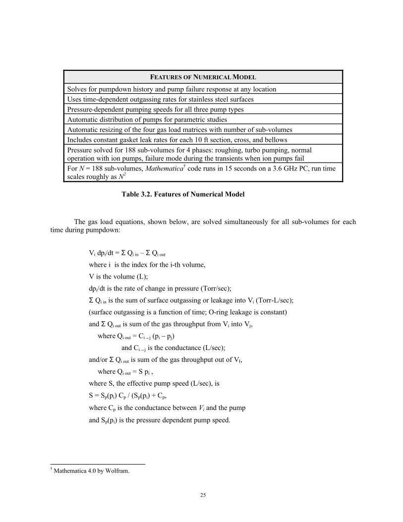
FEATURES OF NUMERICAL MODEL
Solves for pumpdown history and pump failure response at any locationUses time-dependent outgassing rates for stainless steel surfacesPressure-dependent pumping speeds for all three pump types Automatic distribution of pumps for parametric studiesAutomatic resizing of the four gas load matrices with number of sub-volumesIncludes constant gasket leak rates for each 10 ft section, cross, and bellowsPressure solved for 188 sub-volumes for 4 phases: roughing, turbo pumping, normal operation with ion pumps, failure mode during the transients when ion pumps fail For N = 188 sub-volumes, Mathematica† code runs in 15 seconds on a 3.6 GHz PC, run time scales roughly as N2
Table 3.2. Features of Numerical Model
The gas load equations, shown below, are solved simultaneously for all sub-volumes for each time during pumpdown:
Vi dpi/dt = Σ Qi in – Σ Qi out
where i is the index for the i-th volume,V is the volume (L);dpi/dt is the rate of change in pressure (Torr/sec);Σ Qi in is the sum of surface outgassing or leakage into Vi (Torr-L/sec);(surface outgassing is a function of time; O-ring leakage is constant)and Σ Qi out is sum of the gas throughput from Vi into Vj,
where Qi out = Ci→j (pi – pj)and Ci→j is the conductance (L/sec);
and/or Σ Qi out is sum of the gas throughput out of VI,where Qi out = S pi ,
where S, the effective pump speed (L/sec), is
S = Sp(pi) Cp / (Sp(pi) + Cp,
where Cp is the conductance between Vi and the pump
and Sp(pi) is the pressure dependent pump speed.
† Mathematica 4.0 by Wolfram.
26
3.2.2 Outgassing Rate AssumptionsAs discussed earlier, all vacuum-facing surfaces are composed of electro-polished stainless steel.
The numerical fit for the outgassing rate history is a combination of three parts and is shown in Fig. 2.9. The early outgassing rate (first hour) is taken from Roth.† The history from 2 to 80 hours is taken from measurements made from the LANL-APT experiment.†† For our model, the final outgassing rate is assumed to be 1 x 10⁻¹⁰ Torr-L/sec/cm2. For reasonable pump down times as a design goal, the final rate is assumed to occur at 100 hours. Note in Fig. 2.2, the APT data shows that an even lower outgassing rate will be achieved beyond 100 hours. This curve fit represents the outgassing rate history for the first time that the system is pumped down. After the first time and if the system is purged with dry nitrogen, then the outgassing rate will be closer to 10-10 Torr-L/sec/cm2 in the early time. This value or even less will be likely achieved in a few hours provided that good vacuum practices are followed.
3.2.3 Pump Models
For each pump, the dependence of pump speed on local pressure Sp (pi) was scanned from the manufacturer’s catalog and fit to a numerical formula. Figures 3.3, 3.4 and 3.5 show the pump characteristics for the roughing, turbo, and ion pumps, respectively.
The roughing pumps are mounted on the carts and pumped through the turbo pumps. The roughing phase is from 760 Torr to 0.01 Torr. Roughing pumps are represented with a Varian 610 DS (dry scroll) pump with a nominal pump speed of 10 L/sec. The model assumes that two carts are used simultaneously; with only one cart then the roughing time will be twice as long. The gas load balance is solved with an initial pressure at 760 Torr. The roughing time is chosen so that the final beam tube pressure is 0.01 Torr. Next the final pressures for the 188 sub-volumes are saved to provide the initial conditions for the turbo-pumping phase.
The conductance calculations use the formulas for molecular flow. Although the roughing phase is in viscous flow, the conductances would be larger making a slightly quicker pumpdown. However the pumpdown in the roughing phase is mostly dependent on removing the gas in the volumes. Changing the conductance to a very large value (beyond viscous) did little to change the pumpdown time so we just use the simpler molecular flow formulas.
† Roth, A., 1996, Vacuum Technology, (North Holland, Amsterdam) 190.†† APT LEDA CCDTL Phase 3A PDR Appendix 7A, LLNL/APT 99003.
27
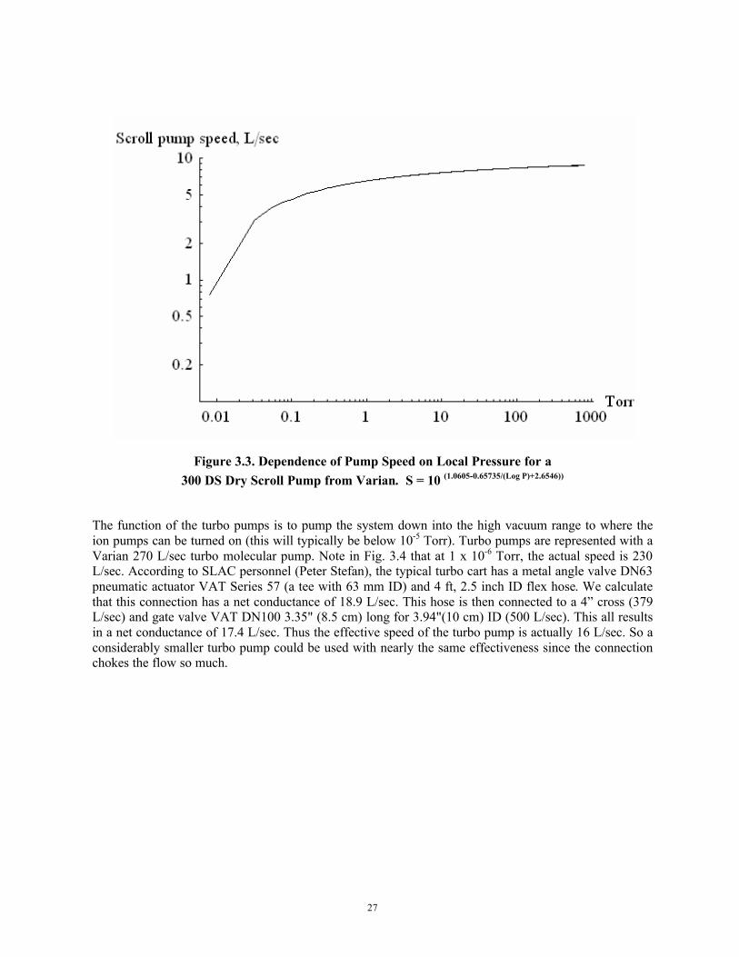
Figure 3.3. Dependence of Pump Speed on Local Pressure for a300 DS Dry Scroll Pump from Varian. S = 10 (1.0605-0.65735/(Log P)+2.6546))
The function of the turbo pumps is to pump the system down into the high vacuum range to where the ion pumps can be turned on (this will typically be below 10-5 Torr). Turbo pumps are represented with a Varian 270 L/sec turbo molecular pump. Note in Fig. 3.4 that at 1 x 10⁻⁶ Torr, the actual speed is 230L/sec. According to SLAC personnel (Peter Stefan), the typical turbo cart has a metal angle valve DN63 pneumatic actuator VAT Series 57 (a tee with 63 mm ID) and 4 ft, 2.5 inch ID flex hose. We calculate that this connection has a net conductance of 18.9 L/sec. This hose is then connected to a 4” cross (379 L/sec) and gate valve VAT DN100 3.35" (8.5 cm) long for 3.94"(10 cm) ID (500 L/sec). This all results in a net conductance of 17.4 L/sec. Thus the effective speed of the turbo pump is actually 16 L/sec. So a considerably smaller turbo pump could be used with nearly the same effectiveness since the connection chokes the flow so much.
28
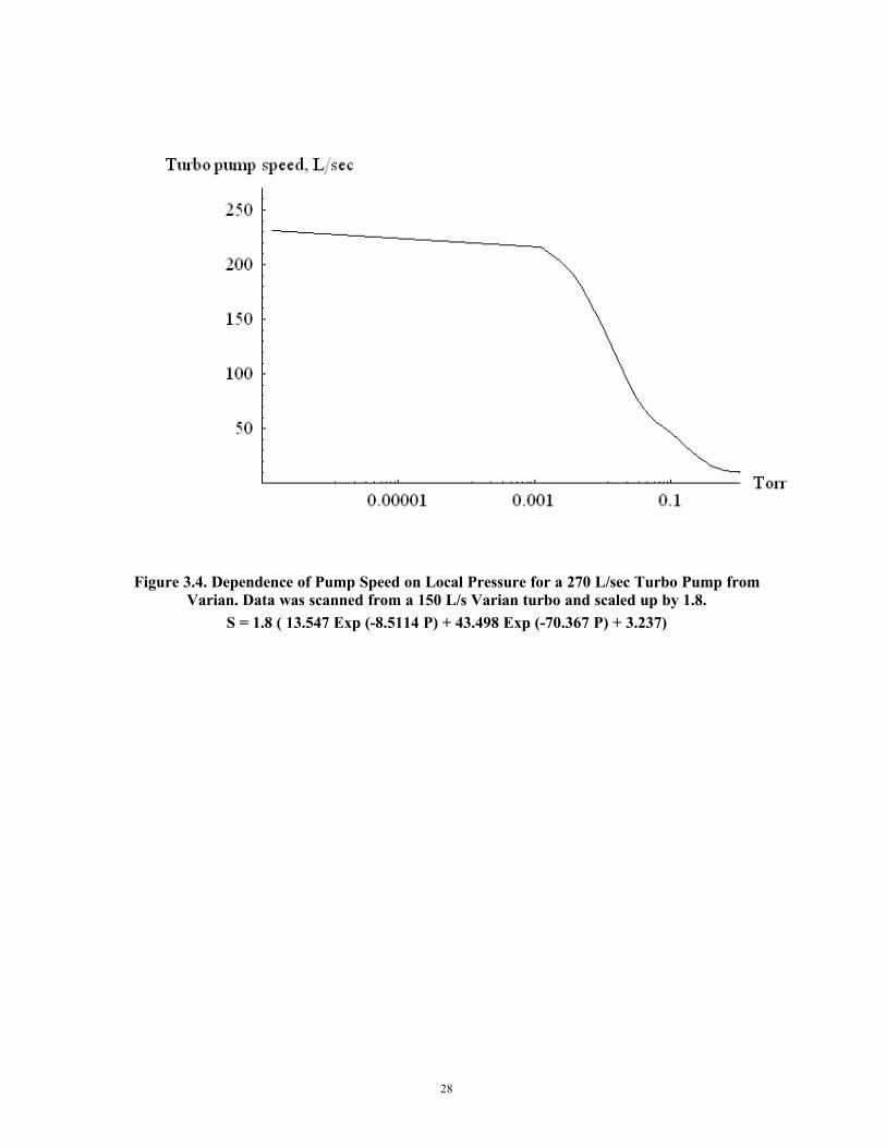
Figure 3.4. Dependence of Pump Speed on Local Pressure for a 270 L/sec Turbo Pump from Varian. Data was scanned from a 150 L/s Varian turbo and scaled up by 1.8.
S = 1.8 ( 13.547 Exp (-8.5114 P) + 43.498 Exp (-70.367 P) + 3.237)
29
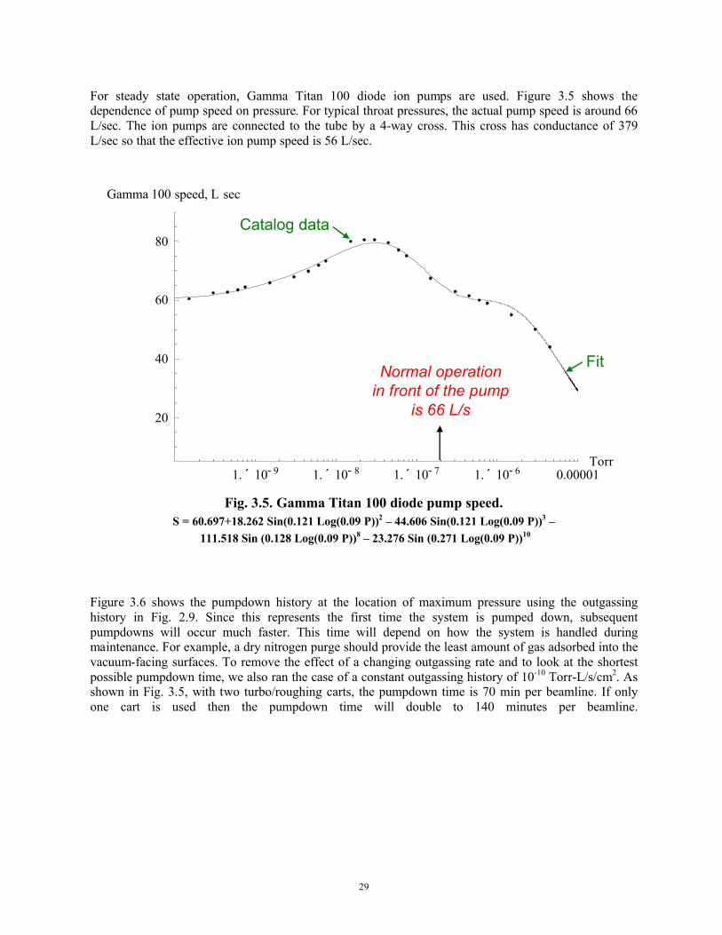
For steady state operation, Gamma Titan 100 diode ion pumps are used. Figure 3.5 shows the dependence of pump speed on pressure. For typical throat pressures, the actual pump speed is around 66L/sec. The ion pumps are connected to the tube by a 4-way cross. This cross has conductance of 379 L/sec so that the effective ion pump speed is 56 L/sec.
Figure 3.3. Dependence of Pump Speed on Local Pressure for aFig. 3.5. Gamma Titan 100 diode pump speed.
S = 60.697+18.262 Sin(0.121 Log(0.09 P))2 – 44.606 Sin(0.121 Log(0.09 P))3 –111.518 Sin (0.128 Log(0.09 P))8 – 23.276 Sin (0.271 Log(0.09 P))10
Figure 3.6 shows the pumpdown history at the location of maximum pressure using the outgassing history in Fig. 2.9. Since this represents the first time the system is pumped down, subsequent pumpdowns will occur much faster. This time will depend on how the system is handled during maintenance. For example, a dry nitrogen purge should provide the least amount of gas adsorbed into the vacuum-facing surfaces. To remove the effect of a changing outgassing rate and to look at the shortest possible pumpdown time, we also ran the case of a constant outgassing history of 10-10 Torr-L/s/cm2. As shown in Fig. 3.5, with two turbo/roughing carts, the pumpdown time is 70 min per beamline. If only one cart is used then the pumpdown time will double to 140 minutes per beamline.
1. ´ 10- 9 1. ´ 10- 8 1. ´ 10- 7 1. ´ 10- 6 0.00001Torr
20
40
60
80
Gamma 100 speed, L sec
Normal operationin front of the pump
is 66 L/s
Catalog data
Fit
1. ´ 10- 9 1. ´ 10- 8 1. ´ 10- 7 1. ´ 10- 6 0.00001Torr
20
40
60
80
Gamma 100 speed, L sec
Normal operationin front of the pump
is 66 L/s
Catalog data
Fit

30
Figure 3.6. Pumpdown History at Location of Maximum Pressureusing Outgassing Rate in Fig. 2.9.
Figure 3.7. Pumpdown History at location of Maximum Pressure for a ConstantOutgassing rate of 10-10 Torr-L/sec/cm2.
100 1000 10000 100000
1€€€€€€€€€€€€€€€€€€€€€€€€€€€€10000000
1. ´ 10- 6
0.0001
0.01
1
100
All pumps: Torr vs Seconds
100 hrs6040 min
Scroll
Turbo
Ion
Pressure,Torr
100
1
10-2
10-4
10-6
10-8
100 1000 10000 100000
1€€€€€€€€€€€€€€€€€€€€€€€€€€€€10000000
1. ´ 10- 6
0.0001
0.01
1
100
All pumps: Torr vs Seconds
100 hrs6040 min
Scroll
Turbo
Ion
Pressure,Torr
100
1
10-2
10-4
10-6
10-8
min7040
Scroll
Turbo
Ion
100 1000 10000seconds
Pressure,Torr
100
10-2
10-4
10-6
1
90min7040
Scroll
Turbo
Ion
100 1000 10000seconds
Pressure,Torr
100
10-2
10-4
10-6
1
90
31
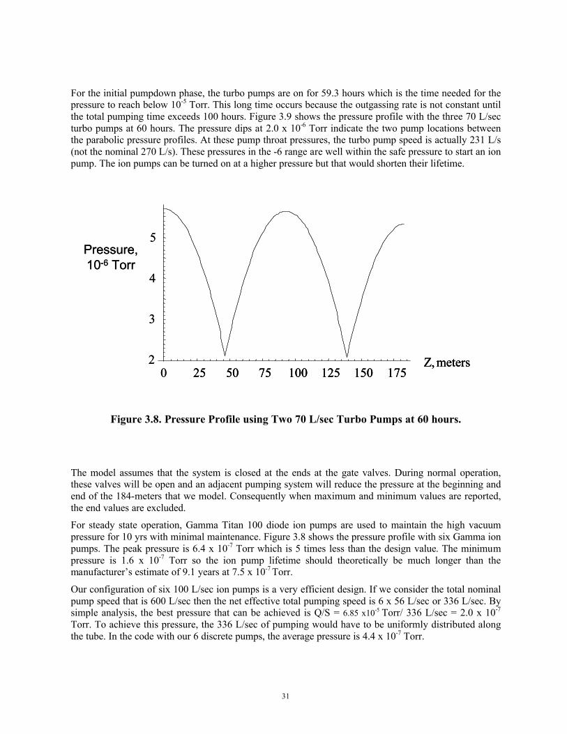
For the initial pumpdown phase, the turbo pumps are on for 59.3 hours which is the time needed for the pressure to reach below 10-5 Torr. This long time occurs because the outgassing rate is not constant until the total pumping time exceeds 100 hours. Figure 3.9 shows the pressure profile with the three 70 L/sec turbo pumps at 60 hours. The pressure dips at 2.0 x 10⁻⁶ Torr indicate the two pump locations between the parabolic pressure profiles. At these pump throat pressures, the turbo pump speed is actually 231 L/s (not the nominal 270 L/s). These pressures in the -6 range are well within the safe pressure to start an ion pump. The ion pumps can be turned on at a higher pressure but that would shorten their lifetime.
Figure 3.8. Pressure Profile using Two 70 L/sec Turbo Pumps at 60 hours.
The model assumes that the system is closed at the ends at the gate valves. During normal operation, these valves will be open and an adjacent pumping system will reduce the pressure at the beginning and end of the 184-meters that we model. Consequently when maximum and minimum values are reported, the end values are excluded.
For steady state operation, Gamma Titan 100 diode ion pumps are used to maintain the high vacuum pressure for 10 yrs with minimal maintenance. Figure 3.8 shows the pressure profile with six Gamma ion pumps. The peak pressure is 6.4 x 10⁻⁷ Torr which is 5 times less than the design value. The minimum pressure is 1.6 x 10⁻⁷ Torr so the ion pump lifetime should theoretically be much longer than the manufacturer’s estimate of 9.1 years at 7.5 x 10⁻⁷ Torr.
Our configuration of six 100 L/sec ion pumps is a very efficient design. If we consider the total nominal pump speed that is 600 L/sec then the net effective total pumping speed is 6 x 56 L/sec or 336 L/sec. By simple analysis, the best pressure that can be achieved is Q/S = 6.85 x10⁻⁵ Torr/ 336 L/sec = 2.0 x 10⁻⁷
Torr. To achieve this pressure, the 336 L/sec of pumping would have to be uniformly distributed along the tube. In the code with our 6 discrete pumps, the average pressure is 4.4 x 10⁻⁷ Torr.
25 50 75 100 125 150 175Z, meters
Pressure,10-6 Torr
2
3
4
5
0 25 50 75 100 125 150 175Z, meters
25 50 75 100 125 150 175Z, meters
Pressure,10-6 Torr
2
3
4
5
0

32
Figure 3.9. Pressure Profile using Six Gamma 100 Ion Pumps at 100 hours.
3.3 Failure Analysis
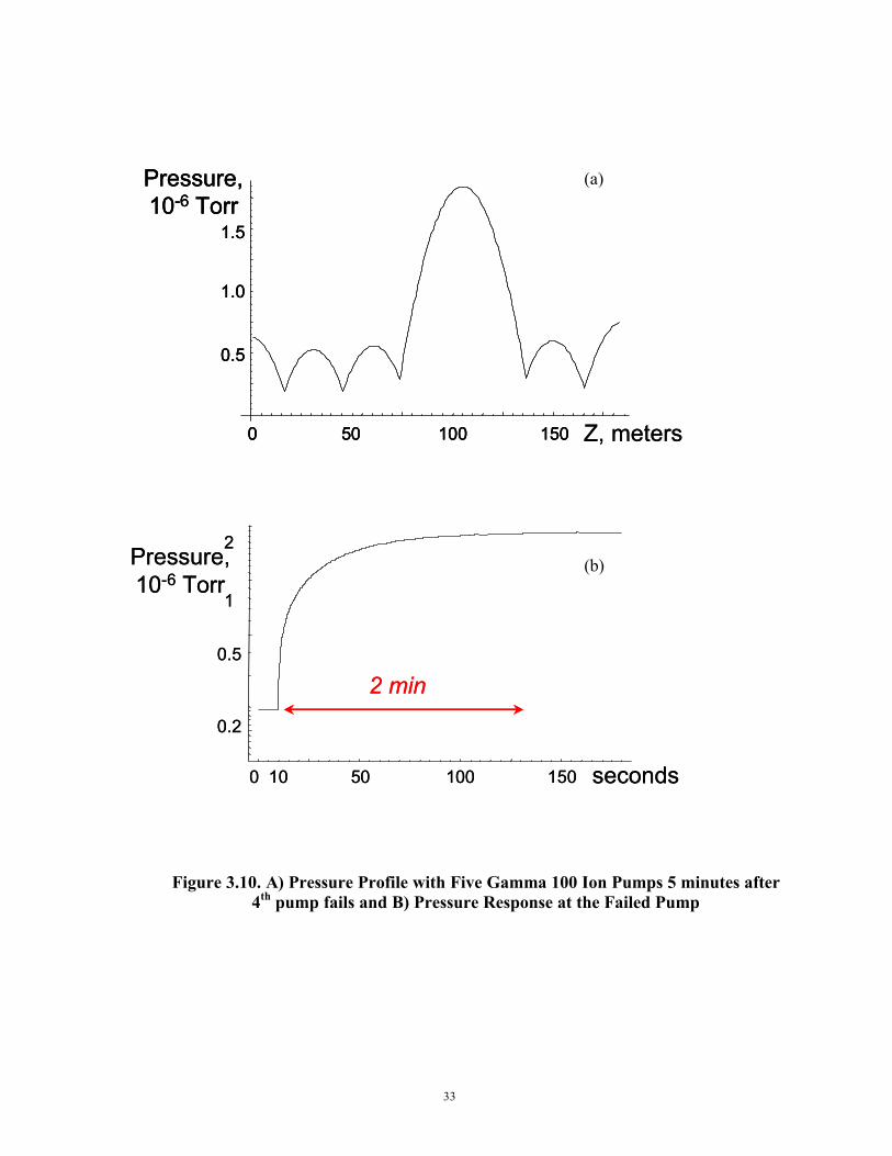
We also studied the system response when one or more ion pumps failed and the turbo pumps were used as a backup. Figures 3.10A and 3.10B shows the pressure profile when the 4th ion pump fails and the time response of the pressure in front of that failed pump. Pressure at the 4th pump increases from 2 x 10-
7 to 2 x 10⁻⁶ Torr within 2 minutes but is still within the maximum design value (abnormal operation) of 6 x 10⁻⁶ Torr. The pump throat pressures are still in the -7 range so that the ion pumps could be operated in this mode for several years and still is within the 10 yr life.
7
Pressure,10-7 Torr
25 50 75 100 125 150 175Z, meters
6
5
4
3
2
7
Pressure,10-7 Torr
25 50 75 100 125 150 175Z, meters
6
5
4
3
2
33
(a)
(b)
Figure 3.10. A) Pressure Profile with Five Gamma 100 Ion Pumps 5 minutes after 4th pump fails and B) Pressure Response at the Failed Pump
0.5
1
2
0.2
Pressure,10-6 Torr
seconds0 10 50 100 150
2 min0.5
1
2
0.2
Pressure,10-6 Torr
seconds0 10 50 100 150
2 min
Pressure,10-6 Torr
1.5
1.0
0.5
0 50 100 150 Z, meters
Pressure,10-6 Torr
1.5
1.0
0.5
0 50 100 150
Pressure,10-6 Torr
1.5
1.0
0.5
0 50 100 150 Z, meters

34
Cases of up to four failures of adjacent ion pumps was modeled and plotted in Fig. 3.11. In the worst case of four ion pumps failing, the pump throat pressure is 1 x 10⁻⁶ Torr which is safe for the pumps but would shorten pump life to a few years. As seen in Fig. 3.11, even three adjacent ion pumps can fail and still have the peak pressure less than the limit of 6 x 10⁻⁶ Torr. Note that only the pumps adjacent to the failed pumps experience only a slight increase in local pressure. The remaining pumps are not affected.
Figure 3.11. Pressure Profile after One, Two, Three, or Four Adjacent Pumps Fail
3.4 System robustness to higher outgassing rates
As discussed earlier, the typical outgassing rate of a clean system is at least 1 x 10⁻¹⁰ Torr-L/s/cm2. If additional leaks develop or the surface is not properly vented with dry nitrogen, then the total system gas load could be higher than the value included in our model. To quantify the system robustness, we also studied how large an outgassing rate that our design could tolerate. Since the seal leak load is small relative to the surface outgassing load, pressures scale with the surface outgassing rate for rates exceeding 1 x 10⁻¹⁰ Torr-L/s/cm2. For all 6 ion pumps working and if the seal leak rate is constant, then, according to our model, a surface outgassing rate of 5.1 x 10⁻¹⁰ Torr-L/s/cm2 would still meet the design value of 3 x 10⁻⁶ Torr. Even with one pump failed, according to our model, a surface outgassing rate of 3.5 x 10⁻¹⁰ Torr-L/s/cm2 would still meet the temporary design value of 6 x 10⁻⁶ Torr for a year until the pump is replaced. Consequently, we believe that our final design meets the specifications with a comfortable margin.
Pressure,10-6 Torr
2
3
4
5
6
7
25 50 75 100 125 150 175Z, meters
Max design during failure(< 1 yr operation)
1 fails
2 fail
3 fail
4 fail
Pressure,10-6 Torr
2
3
4
5
6
7
2
3
4
5
6
7
25 50 75 100 125 150 175Z, meters
Max design during failure(< 1 yr operation)
1 fails
2 fail
3 fail
4 fail
35
4 Mechanical Design
4.1 IntroductionThis section reviews the mechanical design of the x-ray tunnel vacuum system of the Linac
Coherent Light Source (LCLS) project. The x-ray tunnel extends over 200 meters from the Near Experimental Hall (NEH) to the Far Experimental Hall (FEH) at the Stanford Linear Accelerator Center (SLAC).
The structural design of the XVTS has been approved by the SLAC Earthquake Citizens Committee and documented in ERD05-000141-AA. Evaluation of the mechanical strength and deflection under seismic loading has been completed. The seismic loads are per the SLAC document, “Specification for Seismic Design of Buildings, Structures, Equipment, and Systems at the Stanford Linear Accelerator Center” dated December 4, 2000.
4.2 General Description
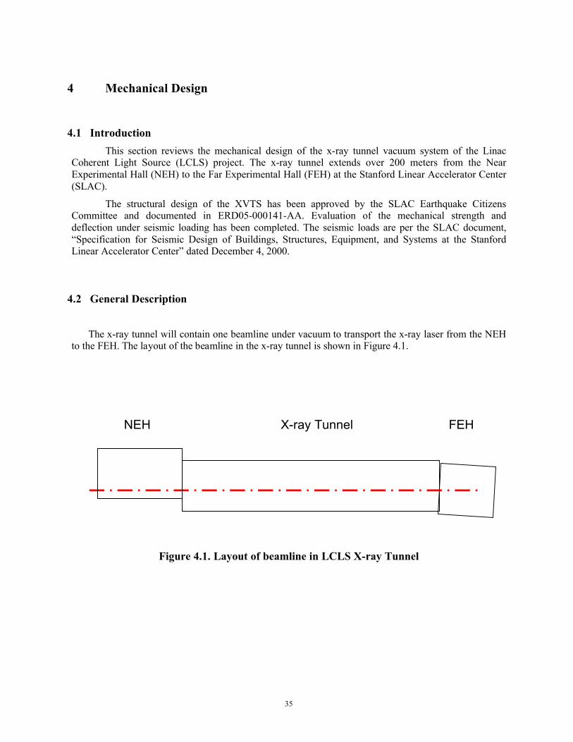
The x-ray tunnel will contain one beamline under vacuum to transport the x-ray laser from the NEH to the FEH. The layout of the beamline in the x-ray tunnel is shown in Figure 4.1.
Figure 4.1. Layout of beamline in LCLS X-ray Tunnel
NEH X-ray Tunnel FEH
36
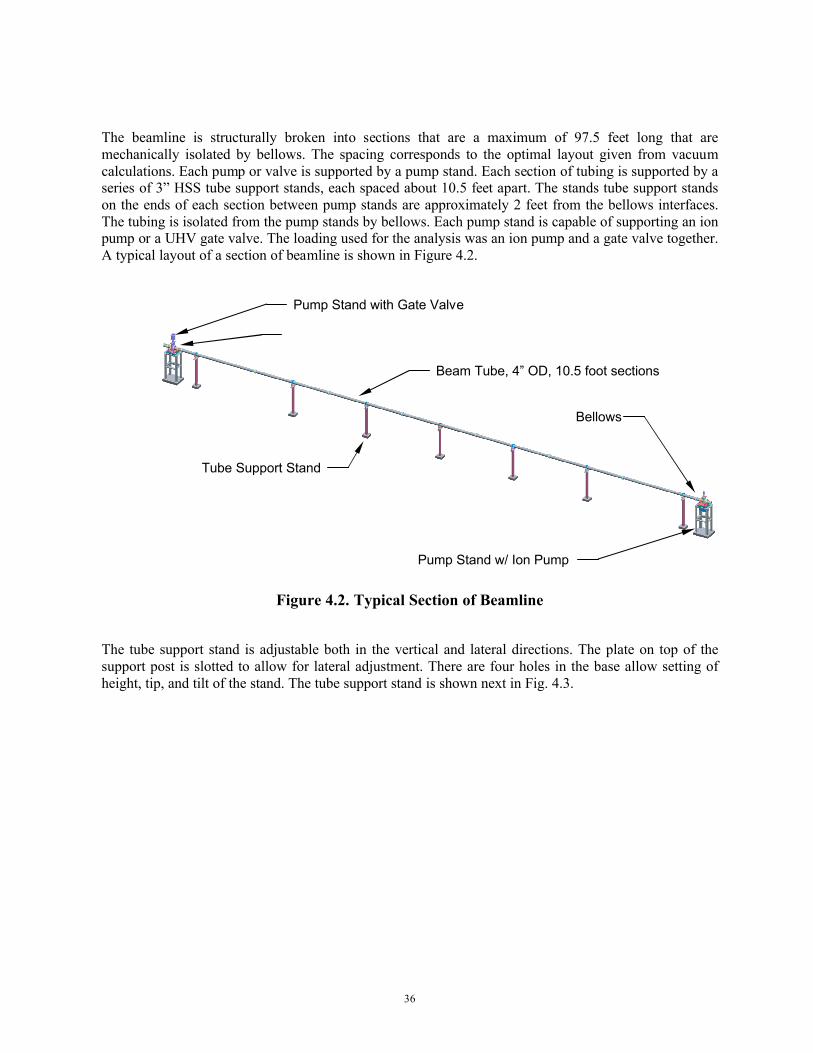
The beamline is structurally broken into sections that are a maximum of 97.5 feet long that are mechanically isolated by bellows. The spacing corresponds to the optimal layout given from vacuum calculations. Each pump or valve is supported by a pump stand. Each section of tubing is supported by a series of 3” HSS tube support stands, each spaced about 10.5 feet apart. The stands tube support stands on the ends of each section between pump stands are approximately 2 feet from the bellows interfaces. The tubing is isolated from the pump stands by bellows. Each pump stand is capable of supporting an ion pump or a UHV gate valve. The loading used for the analysis was an ion pump and a gate valve together. A typical layout of a section of beamline is shown in Figure 4.2.
Figure 4.2. Typical Section of Beamline
The tube support stand is adjustable both in the vertical and lateral directions. The plate on top of the support post is slotted to allow for lateral adjustment. There are four holes in the base allow setting of height, tip, and tilt of the stand. The tube support stand is shown next in Fig. 4.3.
Bellows
Pump Stand with Gate Valve
Beam Tube, 4” OD, 10.5 foot sections
Tube Support Stand
Pump Stand w/ Ion Pump
Bellows

37
Figure 4.3. Tube Support Stand
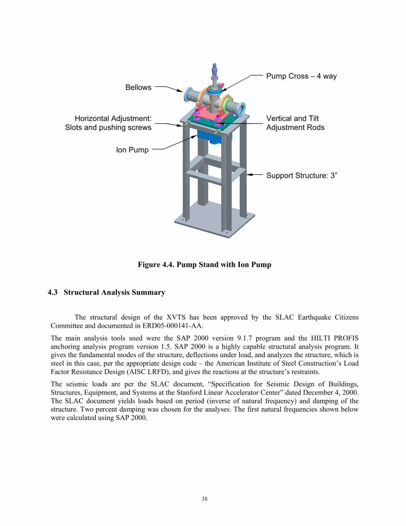
The pump stand design is shown on in Figure 4.4 with an ion pump. It also can support a gate valve. All pump stands will have the same components below the beam-line connection bracket. The valve stand has a different bracket to hold the valve.
The stands have adjustments in five degrees of freedom, with no horizontal adjustment in the beamline direction. None is required for the beamline direction as the bellows will allow for installation tolerances. The formed bellows range of motion is from 6.2 to 7.4 inches in length and allow for ¼” oflateral offset. The stands will have defined lift points for ease of installation.
Tube Support Clamp
Vertical Adjustment Rods
Horizontal Adjustment Slots
Tube Support Post – 3”
38
Figure 4.4. Pump Stand with Ion Pump
4.3 Structural Analysis Summary
The structural design of the XVTS has been approved by the SLAC Earthquake Citizens Committee and documented in ERD05-000141-AA.
The main analysis tools used were the SAP 2000 version 9.1.7 program and the HILTI PROFIS anchoring analysis program version 1.5. SAP 2000 is a highly capable structural analysis program. It gives the fundamental modes of the structure, deflections under load, and analyzes the structure, which is steel in this case, per the appropriate design code – the American Institute of Steel Construction’s Load Factor Resistance Design (AISC LRFD), and gives the reactions at the structure’s restraints.
The seismic loads are per the SLAC document, “Specification for Seismic Design of Buildings, Structures, Equipment, and Systems at the Stanford Linear Accelerator Center” dated December 4, 2000.The SLAC document yields loads based on period (inverse of natural frequency) and damping of the structure. Two percent damping was chosen for the analyses. The first natural frequencies shown below were calculated using SAP 2000.
Pump Cross – 4 wayBellows
Horizontal Adjustment: Slots and pushing screws
Vertical and Tilt Adjustment Rods
Ion Pump
Support Structure: 3”
39
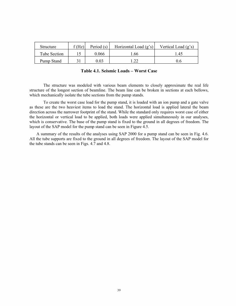
Structure f (Hz) Period (s) Horizontal Load (g’s) Vertical Load (g’s)Tube Section 15 0.066 1.66 1.45Pump Stand 31 0.03 1.22 0.6
Table 4.1. Seismic Loads – Worst Case
The structure was modeled with various beam elements to closely approximate the real life structure of the longest section of beamline. The beam line can be broken in sections at each bellows, which mechanically isolate the tube sections from the pump stands.
To create the worst case load for the pump stand, it is loaded with an ion pump and a gate valve as these are the two heaviest items to load the stand. The horizontal load is applied lateral the beam direction across the narrower footprint of the stand. While the standard only requires worst case of either the horizontal or vertical load to be applied, both loads were applied simultaneously in our analyses, which is conservative. The base of the pump stand is fixed to the ground in all degrees of freedom. The layout of the SAP model for the pump stand can be seen in Figure 4.5.
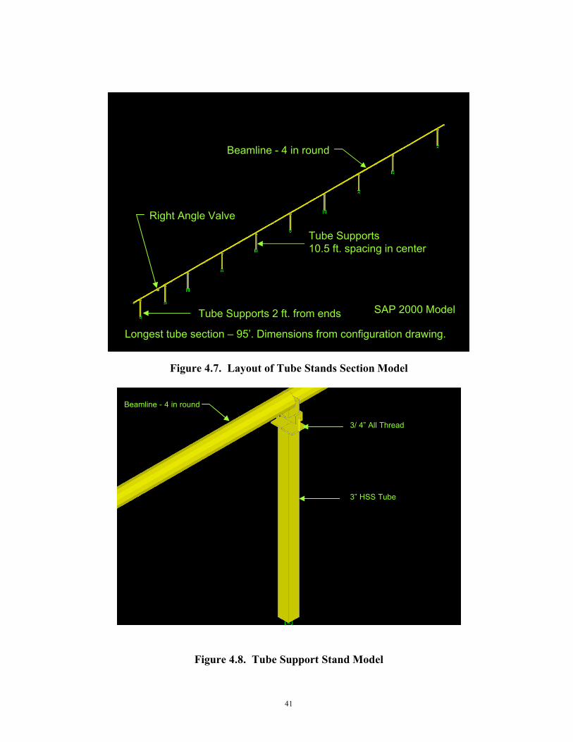
A summary of the results of the analyses using SAP 2000 for a pump stand can be seen in Fig. 4.6.All the tube supports are fixed to the ground in all degrees of freedom. The layout of the SAP model for the tube stands can be seen in Figs. 4.7 and 4.8.

40
Figure 4.5. Pump Stand in SAP 2000 model
Figure 4.6. Summary of Pump Stand results using SAP 2000 model
Pump Stand
Gate Valve Mass
Ion Pump
Pump Cross
Maximum deflections:0.000” Beamline0.010” Lateral0.000” VerticalFormed bellows allow 0.25” lateral offset
Maximum stress:18% of allowable stress in 3/4” threaded supportsPer AISC LRFD
First mode 31 Hz
Load applied in lateral and vertical directions
41
Figure 4.7. Layout of Tube Stands Section Model
Figure 4.8. Tube Support Stand Model
Beamline - 4 in round
3” HSS Tube
3/ 4” All Thread
Beamline - 4 in round
Tube Supports10.5 ft. spacing in center
SAP 2000 ModelTube Supports 2 ft. from ends
Right Angle Valve
Longest tube section – 95’. Dimensions from configuration drawing.
42
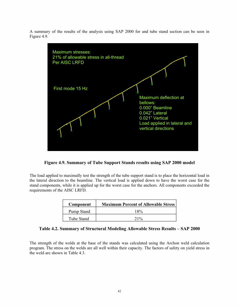
A summary of the results of the analysis using SAP 2000 for and tube stand section can be seen in Figure 4.9.
Figure 4.9. Summary of Tube Support Stands results using SAP 2000 model
The load applied to maximally test the strength of the tube support stand is to place the horizontal load in the lateral direction to the beamline. The vertical load is applied down to have the worst case for the stand components, while it is applied up for the worst case for the anchors. All components exceeded the requirements of the AISC LRFD.
Component Maximum Percent of Allowable StressPump Stand 18%Tube Stand 21%
Table 4.2. Summary of Structural Modeling Allowable Stress Results – SAP 2000
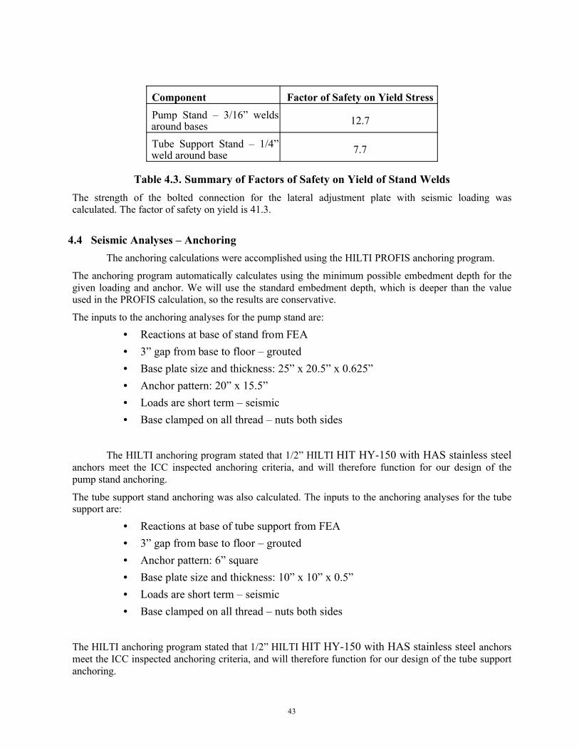
The strength of the welds at the base of the stands was calculated using the Archon weld calculation program. The stress on the welds are all well within their capacity. The factors of safety on yield stress in the weld are shown in Table 4.3.
Maximum deflection at bellows:0.000” Beamline0.042” Lateral0.021” VerticalLoad applied in lateral and vertical directions
Maximum stresses:21% of allowable stress in all-threadPer AISC LRFD
First mode 15 Hz
43
Component Factor of Safety on Yield StressPump Stand – 3/16” welds around bases 12.7
Tube Support Stand – 1/4” weld around base 7.7
Table 4.3. Summary of Factors of Safety on Yield of Stand WeldsThe strength of the bolted connection for the lateral adjustment plate with seismic loading was calculated. The factor of safety on yield is 41.3.
4.4 Seismic Analyses – AnchoringThe anchoring calculations were accomplished using the HILTI PROFIS anchoring program.
The anchoring program automatically calculates using the minimum possible embedment depth for the given loading and anchor. We will use the standard embedment depth, which is deeper than the value used in the PROFIS calculation, so the results are conservative.
The inputs to the anchoring analyses for the pump stand are:
• Reactions at base of stand from FEA• 3” gap from base to floor – grouted• Base plate size and thickness: 25” x 20.5” x 0.625”• Anchor pattern: 20” x 15.5”• Loads are short term – seismic• Base clamped on all thread – nuts both sides
The HILTI anchoring program stated that 1/2” HILTI HIT HY-150 with HAS stainless steel anchors meet the ICC inspected anchoring criteria, and will therefore function for our design of the pump stand anchoring.
The tube support stand anchoring was also calculated. The inputs to the anchoring analyses for the tubesupport are:
• Reactions at base of tube support from FEA• 3” gap from base to floor – grouted• Anchor pattern: 6” square• Base plate size and thickness: 10” x 10” x 0.5”• Loads are short term – seismic• Base clamped on all thread – nuts both sides
The HILTI anchoring program stated that 1/2” HILTI HIT HY-150 with HAS stainless steel anchors meet the ICC inspected anchoring criteria, and will therefore function for our design of the tube support anchoring.
44
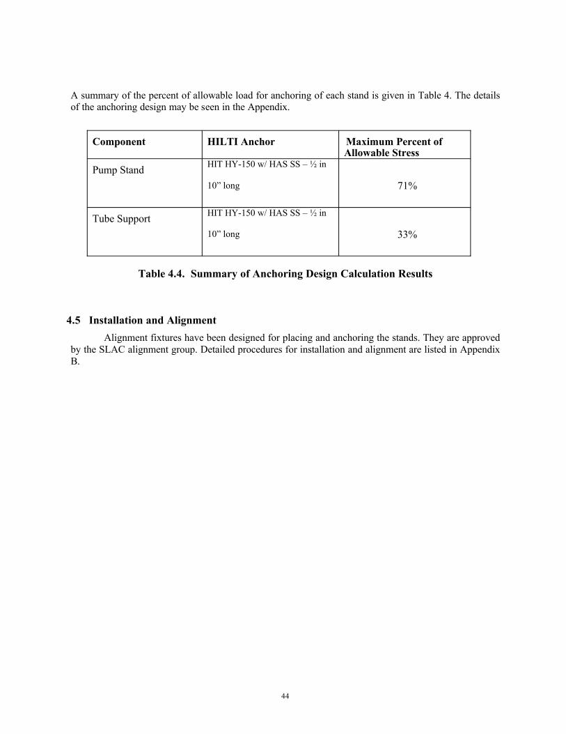
A summary of the percent of allowable load for anchoring of each stand is given in Table 4. The details of the anchoring design may be seen in the Appendix.
Component HILTI Anchor Maximum Percent of Allowable Stress
Pump Stand HIT HY-150 w/ HAS SS – ½ in
10” long 71%
Tube Support HIT HY-150 w/ HAS SS – ½ in
10” long 33%
Table 4.4. Summary of Anchoring Design Calculation Results
4.5 Installation and AlignmentAlignment fixtures have been designed for placing and anchoring the stands. They are approved
by the SLAC alignment group. Detailed procedures for installation and alignment are listed in Appendix B.
45
5 Instrumentation and Control
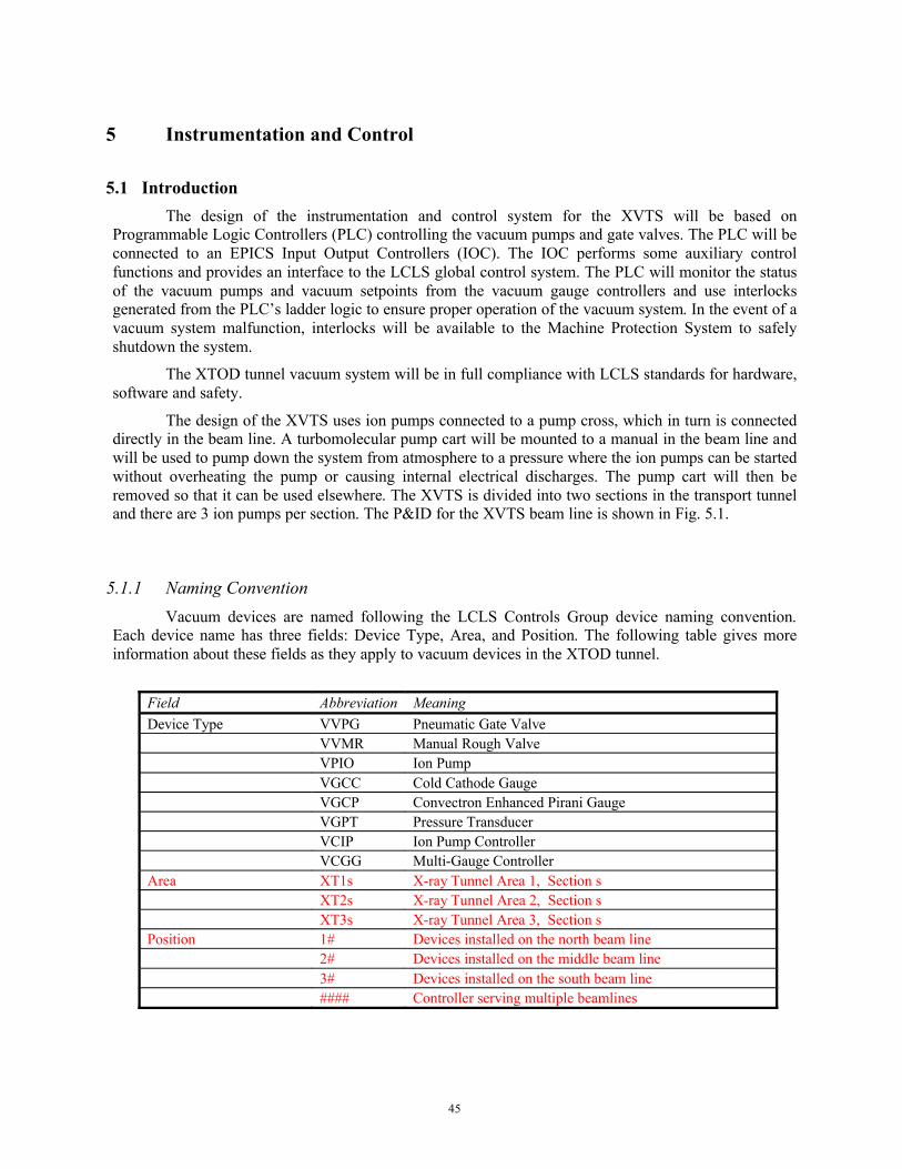
5.1 IntroductionThe design of the instrumentation and control system for the XVTS will be based on
Programmable Logic Controllers (PLC) controlling the vacuum pumps and gate valves. The PLC will be connected to an EPICS Input Output Controllers (IOC). The IOC performs some auxiliary control functions and provides an interface to the LCLS global control system. The PLC will monitor the status of the vacuum pumps and vacuum setpoints from the vacuum gauge controllers and use interlocks generated from the PLC’s ladder logic to ensure proper operation of the vacuum system. In the event of a vacuum system malfunction, interlocks will be available to the Machine Protection System to safely shutdown the system.
The XTOD tunnel vacuum system will be in full compliance with LCLS standards for hardware, software and safety.
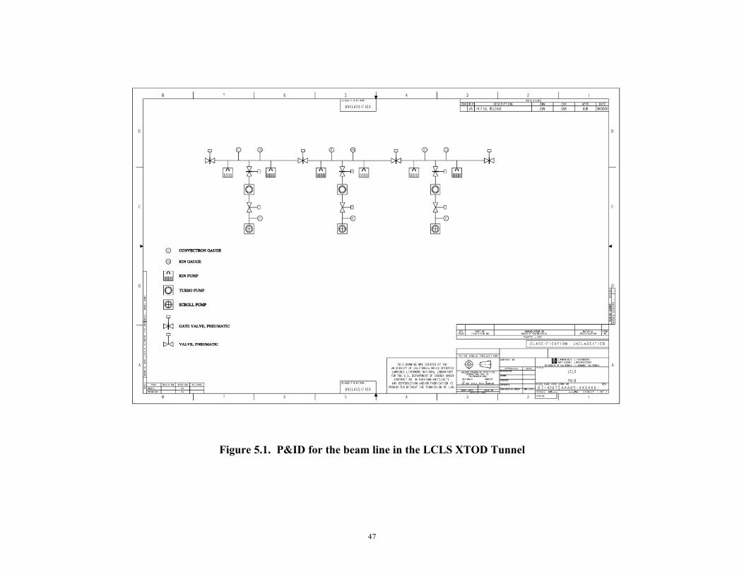
The design of the XVTS uses ion pumps connected to a pump cross, which in turn is connected directly in the beam line. A turbomolecular pump cart will be mounted to a manual in the beam line and will be used to pump down the system from atmosphere to a pressure where the ion pumps can be started without overheating the pump or causing internal electrical discharges. The pump cart will then be removed so that it can be used elsewhere. The XVTS is divided into two sections in the transport tunnel and there are 3 ion pumps per section. The P&ID for the XVTS beam line is shown in Fig. 5.1.
5.1.1 Naming ConventionVacuum devices are named following the LCLS Controls Group device naming convention.
Each device name has three fields: Device Type, Area, and Position. The following table gives more information about these fields as they apply to vacuum devices in the XTOD tunnel.
Field Abbreviation MeaningDevice Type VVPG Pneumatic Gate Valve
VVMR Manual Rough ValveVPIO Ion PumpVGCC Cold Cathode GaugeVGCP Convectron Enhanced Pirani GaugeVGPT Pressure TransducerVCIP Ion Pump ControllerVCGG Multi-Gauge Controller
Area XT1s X-ray Tunnel Area 1, Section sXT2s X-ray Tunnel Area 2, Section sXT3s X-ray Tunnel Area 3, Section s
Position 1# Devices installed on the north beam line2# Devices installed on the middle beam line3# Devices installed on the south beam line#### Controller serving multiple beamlines
46
Key:
Section s: 0=all; 1, 2, 3=Z distance
#: unit number for devices
####: area+section, area+section for two devices served by controller
47
Figure 5.1. P&ID for the beam line in the LCLS XTOD Tunnel
48
5.2 Vacuum Control System Architecture
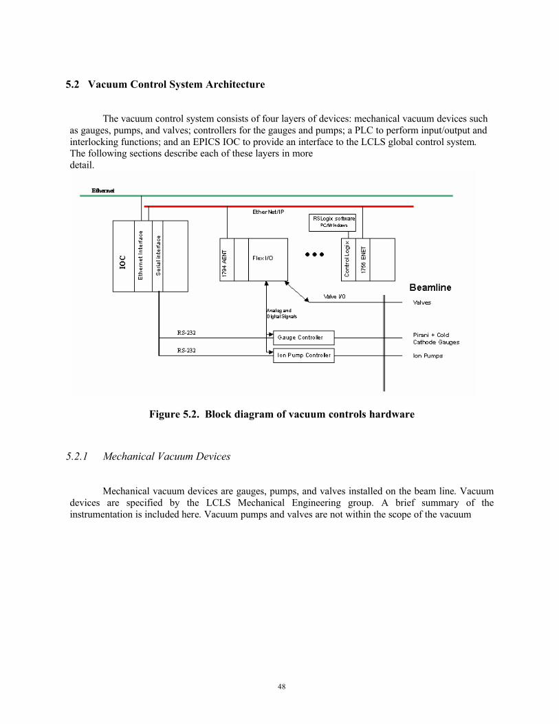
The vacuum control system consists of four layers of devices: mechanical vacuum devices such as gauges, pumps, and valves; controllers for the gauges and pumps; a PLC to perform input/output and interlocking functions; and an EPICS IOC to provide an interface to the LCLS global control system. The following sections describe each of these layers in more detail.
Figure 5.2. Block diagram of vacuum controls hardware
5.2.1 Mechanical Vacuum Devices
Mechanical vacuum devices are gauges, pumps, and valves installed on the beam line. Vacuum devices are specified by the LCLS Mechanical Engineering group. A brief summary of the instrumentation is included here. Vacuum pumps and valves are not within the scope of the vacuum
49
controls effort. See Vacuum Controls <-> Vacuum Mechanical (ICD 1.1-510) and LCLS Mechanical Vacuum Specifications (ESD 1.1-302) for more information on gauges, pumps and valves.
5.2.2 InstrumentationAlthough vacuum pressure can be derived from ion pump current, the control system needs to
measure the vacuum pressure with a high vacuum gauge before the ion pumps are started. An ion pump requires a moderately high vacuum condition to be established by the turbo cart before it can be started. The XVTS vacuum system is designed to start the ion pumps at a vacuum of 1x10⁻⁵ Torr. While ion pumps can be started at higher pressures, starting the ion pumps at 1x10⁻⁵ Torr will significantly extent their operating life.
Another reason for using a high vacuum gauge rather than relying solely on an ion pump’s current to determine the vacuum pressure is that any leakage current in the pump, cable or connector will cause the ion pump controller to give a false pressure reading.
To provide the most robust control system, an independent high vacuum gauge is required to determine if the turbo cart has pumped out the XVTS to a sufficient vacuum condition for the ion pumps to be started. An independent high vacuum gauge also might be able to help diagnose problems if the ion pump controller is giving false readings. The design calls for a high vacuum gauge to be mounted on each ion pump station, for a total of six high vacuum gauges on the XVTS.
The gauge that has been selected is a MKS Type 422 inverted magnetron cold cathode gauge. The Type 422 is identical to the standard Type 421 cold cathode gauge except that is uses LEMO type connectors which are bakeable to 250° C and are radiation resistant.
One convection enhanced pirani gauge will be mounted at each ion pump station of the XVTS. A convection enhanced pirani is used to measure pressure from atmosphere down to the milli-Torr range. The convection enhanced pirani gauge will be useful to monitor the vacuum system during pumpdown from atmosphere. The convection enhanced pirani gauge was selected because it is more accurate at the higher pressures than a thermocouple gauge or a basic pirani gauge since it has a temperature compensated heat sensor and can measure convection current. The gauge that has been selected is the MKS Type 317.
A quadrupole type residual gas analyzer (RGA) with an electron multiplier will be available to measure the partial pressure of gas species in the vacuum system. This is an important diagnostic tool for high vacuum systems and the design calls for one RGA in each of the turbo carts.
5.2.3 ControllersControllers are standalone devices that supply power to and provide status of vacuum gauges
and ion pumps. Controllers are installed in racks underneath the beamline near the devices they control, providing a means of local control.
The LCLS Controls Group selects the controllers for the vacuum system. The selection of gauge and pump controllers was a collaborative decision between controls personnel and mechanical engineering personnel at SLAC, Lawrence Livermore National Lab, and Argonne National Lab.
5.2.4 Vacuum Racks/CablingFive instrumentation and control equipment racks will be assembled to contain slow controls for
operation of the X-Ray tunnel beam line vacuum system. The racks are designed to fit under the beam line. The racks measure 28.50 wide x 49.19 high x 36.00 inches deep. They are single-bay and will
50
accommodate 24U of rack panel space. They are constructed of welded steel and will meet Bell-Core Zone 4 seismic requirements.
The racks typically contain Gamma ion pump power supplies MKS multi-gauge controllers, Allen-Bradley Control Logix industrial controls, and Cisco network servers and switches. The racks areconfigured to accommodate all vacuum and network hardware.
The ion pump and vacuum gauge controllers both contain high voltage at 7 kVdc and 4 kVdc respectively. The racks will have a lockable rear door to prevent unauthorized or accidental removal of HV cables from the rear panel connectors on the controllers. High voltage safety will require proper administrative control over rack access keys.
LOTO of racks will take place at a wall mounted disconnect switch adjacent to each rack. This allows a disconnect means “within sight” (50ft) of the rack.
The delivered racks will contain I/O hardware for the beam line and vacuum and gauge controllers for the 0° beam line, to be installed.
Racks and vacuum hardware will be delivered to LLNL’s Engineering Manufacturing Services Group for assembly and wiring. They will then be operated and evaluated utilizing the vacuum test stands in B141 by the LCLS control systems group. Racks will then be transported to the tunnel for installation by LCLS cable plant labor force. This same group will install tray, conduit, long-haul cable and service power to the racks. Network configuration will be installed and tested through collaboration between the LCLS control groups.
The list of electrical drawings for construction and installation of the SLAC LCLS X-Ray Tunnel Vacuum Controls System are listed in Appendix C.
5.3 Programmable Logic Controller (PLC)A Programmable Logic Controller (PLC) is a small and rugged computer with various input and
output cards available, widely used in factory automation. The vacuum PLC serves two purposes: it is the primary control system interface for status and control of vacuum controllers, and it performs vacuum interlock functions. It communicates with the controllers using 24V digital or 0-10V analog signals.
5.3.1 Allen-Bradley PLCThe vacuum PLC is a ControlLogix PLC made by Allen-Bradley. A master PLC crate holds a
CPU module, model 1756-L61. Ether/IP modules are used for communication between the master crate and I/O blocks. The Ether-IP module also connects the master PLC crate to the EPICS control system network. Various digital and analog input and output modules are installed in all the PLC I/O blocks built from Allen-Bradley 1794 (“Flex-I/O”); PLC crate and I/O block profiles and lists of PLC input and output signals are provided in final drawings [Appendix].
Note that the master PLC does not control only the XVTS I/O blocks; it also controls I/O blocks in the Front-End enclosure that have similar vacuum characteristics.
The PLC executes ladder logic code programmed with Allen-Bradley RSLogix software installed on a Windows PC. After the code has been downloaded to the PLC, the PLC is a standalone device that does not require a network connection to execute its code. The PLC used for the vacuum
51
system stores its logic code in non-volatile memory, meaning that it retains its programmed code after a power failure without need for a battery backup.
5.3.2 Uninterruptible Power Supply (UPS) for PLC In a system with many PLC crates controlled by a single processor in the master PLC crate, a
power failure of the master PLC crate could create an unsafe condition. If the master crate loses power and the slave crates do not lose power, all the output signals originating in the slave crates remain in the states they were in when the master crate lost power. For example, pumps controlled by the slave crates remain on if they had previously been turned on, valves remain open if they had previously been open, and interlock output signals sent to other subsystems remain in the states they were in before the power loss.
In order to mitigate this potentially unsafe condition, the master PLC crate is equipped with an uninterruptible power supply (UPS). In the event of an incoming power failure, the UPS provides temporary power to the master PLC crate and alerts the PLC of the power failure. The master PLC crate notifies the EPICS control system that power has been lost and initiates a safe shutdown procedure for the vacuum system master.
5.4 Experimental Physics Industrial Control System (EPICS) Input Output Controller (IOC)The EPICS Input Output Controller (IOC) is a VME single board computer communicating on
the global control system Ethernet network. The IOC communicates with vacuum devices in two ways: (1) The IOC can send commands to and receive status from the PLC over the Ethernet network using the EPICS ether-ip driver; and (2) The IOC communicates with some vacuum controllers via RS-232 serial links.
5.4.1 Ether-IP DriverThe EPICS ether-ip driver allows an EPICS IOC to read and write “tags” stored on a PLC. This
makes it possible to transfer all the vacuum information stored in the PLC to an EPICS database, where it can be viewed by vacuum system users and archived by the global control system. The driver also allows the EPICS IOC to write to tags on the PLC, providing a means for EPICS to control devices connected to the PLC. The ether-ip driver does not have the capability of changing the ladder logic programming of the PLC.
5.4.2 RS-232 Serial ConnectionsVacuum controllers with RS-232 serial interfaces are connected to a terminal server, which is
connected to the EPICS IOC on the Ethernet network. This allows the EPICS IOC to communicate directly with those controllers. This serial link is used for non-essential status and control of the vacuum controllers; the PLC is used for primary control and status of devices and for interlocks. The vacuum control system is designed to function properly even when the RS-232 serial links are not functional.
5.5 Other EPICS Hardware and SoftwareThe XVTS system will re-use LCLS-wide standard hardware and software throughout; only the
configuration of lists of Process Variable names; synoptic displays; and operational sequences (not otherwise provided within the PLC) will be specific to XVTS. Common items will be reviewed as part of Global Controls and thus are beyond the scope of this review. Typical common items include: VME

52
crate and single-board computers; IOC operating systems and EPICS IOC base software; network hardware; servers and client-side operating systems; synoptics display software; synoptics screens addressing maintenance requirements at the device or controller level; trending and analysis software; long-term data archiving and retrieval software. A typical EPICS Control System block diagram is illustrated in Fig. 5.3.
Figure 5.3. EPICS System Bloc Diagram for XVTS
The vacuum control system will use ladder logic in the PLCs. Ladder logic describes the sequence of switch closures, interlocks and process control setpoints that have to be executed in order to energize a valve or start a vacuum pump. The start up and operation of any vacuum system will in general have the same basic sequence of switch closures, interlocks and setpoints and therefore the ladder logic can become part of a toolkit of software that can be re-used.
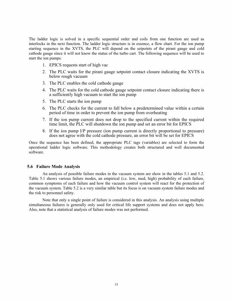
53
The ladder logic is solved in a specific sequential order and coils from one function are used as interlocks in the next function. The ladder logic structure is in essence, a flow chart. For the ion pump starting sequence in the XVTS, the PLC will depend on the setpoints of the pirani gauge and cold cathode gauge since it will not know the status of the turbo cart. The following sequence will be used to start the ion pumps:
1. EPICS requests start of high vac2. The PLC waits for the pirani gauge setpoint contact closure indicating the XVTS is
below rough vacuum3. The PLC enables the cold cathode gauge4. The PLC waits for the cold cathode gauge setpoint contact closure indicating there is
a sufficiently high vacuum to start the ion pump5. The PLC starts the ion pump6. The PLC checks for the current to fall below a predetermined value within a certain
period of time in order to prevent the ion pump from overheating7. If the ion pump current does not drop to the specified current within the required
time limit, the PLC will shutdown the ion pump and set an error bit for EPICS8. If the ion pump I/P pressure (ion pump current is directly proportional to pressure)
does not agree with the cold cathode pressure, an error bit will be set for EPICSOnce the sequence has been defined, the appropriate PLC tags (variables) are selected to form the operational ladder logic software. This methodology creates both structured and well documented software.
5.6 Failure Mode AnalysisAn analysis of possible failure modes in the vacuum system are show in the tables 5.1 and 5.2.
Table 5.1 shows various failure modes, an empirical (i.e. low, med, high) probability of each failure, common symptoms of each failure and how the vacuum control system will react for the protection of the vacuum system. Table 5.2 is a very similar table but its focus is on vacuum system failure modes and the risk to personnel safety.
Note that only a single point of failure is considered in this analysis. An analysis using multiple simultaneous failures is generally only used for critical life support systems and does not apply here. Also, note that a statistical analysis of failure modes was not performed.

54
Table 5.1. Failure Analysis and Control System Response for Machine Protection
System Failure or Condition Probability Symptom PLC Response/Interlock
Scroll and Turbo Pumps
Scroll pump head failure
Low/med - failures are usually due to lack of periodic maintenance (every 10,000 hours)
Low base pressureLow pump speed
Vacuum gauge monitoring foreline pressurePLC interlock will shutdown scroll pumpPLC interlock will shutdown turboPLC interlock will close turbo gate valvePLC sends scroll pump fault message to EPICS
Scroll pump motor failure
Low - motor bearing or winding failure uncommon
High motor current or windings open or short
Motor control circuit (or circuit breaker) will shutdown the scroll pump and send fault signal to PLCPLC interlock will shutdown turboPLC interlock will close turbo gate valvePLC sends scroll pump fault message to EPICS
Scroll pump gas load too high
Low/med - vacuum system leak or contamination High motor current
System will not pump down, PLC will timeout,stop pump, send timeout message to EPICSScroll pump will overheat, motor control circuit will shutdown the scroll pump and send fault signal to PLCPLC interlock will shutdown turboPLC interlock will close turbo gate valve to protectscroll pump
PLC sends scroll pump fault message to EPICS
Turbo pump bearing failure
Low - modern ceramic bearings are very reliable
High motor tempHigh motor current
Turbo controller will provide safe shutdown and send fault signal to PLCPLC interlock will close turbo gate valvePLC sends turbo fault message to EPICS
Turbo rotor crash
Low - Unless turbo ingests foreign object or is subject to multiple atmospheric vents while operating at full speed
Sudden drop in RPMs
Turbo controller will shutdown pump and sendfault signal to PLCPLC interlock will close turbo gate valvePLC sends turbo fault message to EPICS
Turbo gas load too high
Low/med - vacuum system leak or contamination
High motor currentHigh motor tempLow RPMs
Turbo controller will provide safe shutdown and send fault signal to PLCPLC interlock will close turbo gate valve to protect turbo PLC sends turbo fault message to EPICS
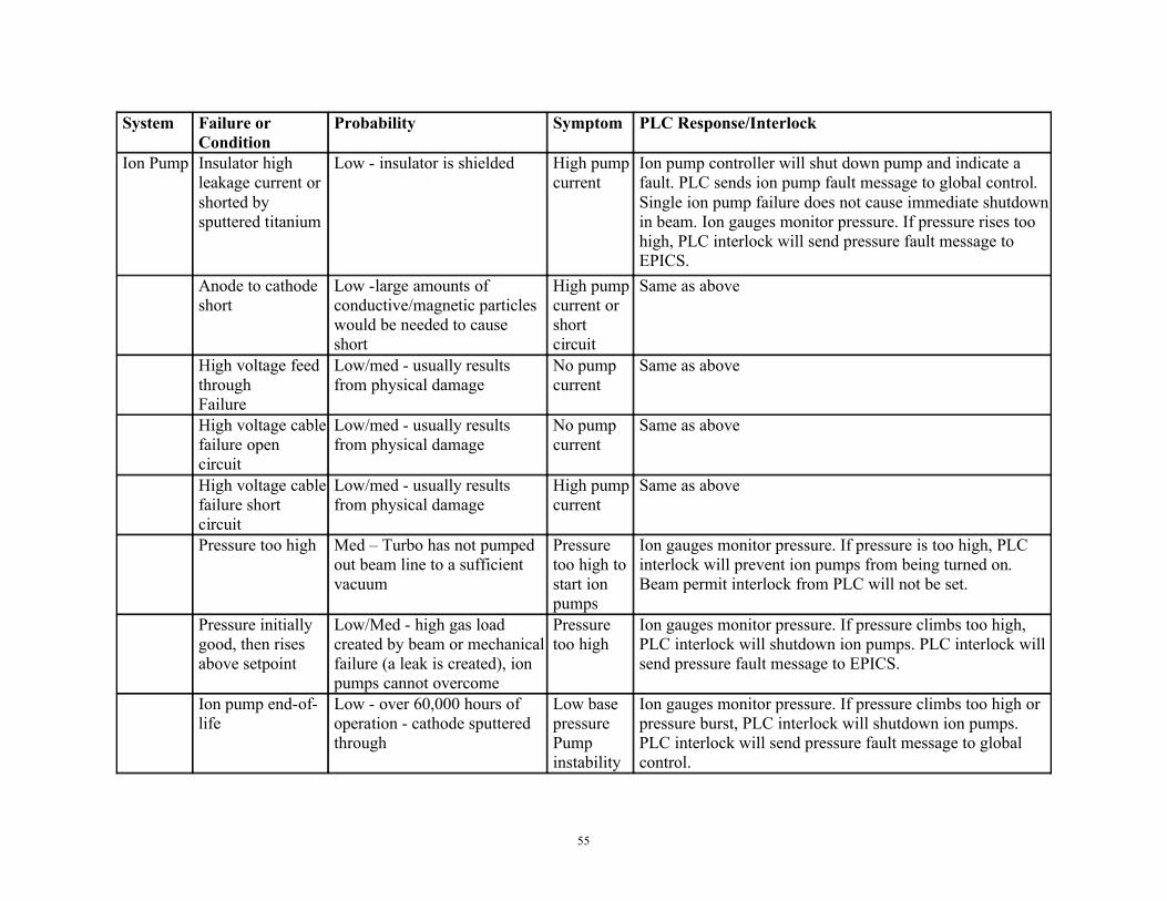
55
System Failure or Condition
Probability Symptom PLC Response/Interlock
Ion Pump Insulator high leakage current or shorted by sputtered titanium
Low - insulator is shielded High pump current
Ion pump controller will shut down pump and indicate a fault. PLC sends ion pump fault message to global control. Single ion pump failure does not cause immediate shutdown in beam. Ion gauges monitor pressure. If pressure rises too high, PLC interlock will send pressure fault message to EPICS.
Anode to cathode short
Low -large amounts of conductive/magnetic particles would be needed to cause short
High pump current or short circuit
Same as above
High voltage feed throughFailure
Low/med - usually results from physical damage
No pump current
Same as above
High voltage cable failure open circuit
Low/med - usually results from physical damage
No pump current
Same as above
High voltage cable failure short circuit
Low/med - usually results from physical damage
High pump current
Same as above
Pressure too high Med – Turbo has not pumped out beam line to a sufficient vacuum
Pressure too high to start ion pumps
Ion gauges monitor pressure. If pressure is too high, PLC interlock will prevent ion pumps from being turned on. Beam permit interlock from PLC will not be set.
Pressure initially good, then rises above setpoint
Low/Med - high gas load created by beam or mechanical failure (a leak is created), ion pumps cannot overcome
Pressure too high
Ion gauges monitor pressure. If pressure climbs too high, PLC interlock will shutdown ion pumps. PLC interlock will send pressure fault message to EPICS.
Ion pump end-of-life
Low - over 60,000 hours of operation - cathode sputtered through
Low base pressurePump instability
Ion gauges monitor pressure. If pressure climbs too high or pressure burst, PLC interlock will shutdown ion pumps. PLC interlock will send pressure fault message to global control.
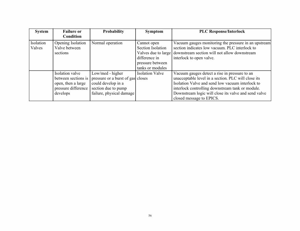
56
System Failure or Condition
Probability Symptom PLC Response/Interlock
Isolation Valves
Opening Isolation Valve between sections
Normal operation Cannot open Section Isolation Valves due to large difference in pressure between tanks or modules
Vacuum gauges monitoring the pressure in an upstream section indicates low vacuum. PLC interlock to downstream section will not allow downstream interlock to open valve.
Isolation valve between sections is open, then a large pressure difference develops
Low/med - higher pressure or a burst of gas could develop in a section due to pump failure, physical damage
Isolation Valve closes
Vacuum gauges detect a rise in pressure to an unacceptable level in a section. PLC will close its Isolation Valve and send low vacuum interlock to interlock controlling downstream tank or module. Downstream logic will close its valve and send valve closed message to EPICS.

57
Table 5.2. Failure Analysis and Control System Response for Personnel Protection
System Symptom Failure or Condition Risk to Personnel Response/ControlScroll Pump
High motor current
Very high gas loads for extended periods
Motor temp could become hot enough to melt conductor insulation and cause electrical fire
Properly sized and installed UL listed thermal overloads in accordance with the NEC will trip magnetic starter circuit off. PLC will indicate pump has stopped via auxiliary contact on magnetic starter.
High motor current
Locked rotor due to bearing failure or pump head failure
Motor temp could become hot enough to melt conductor insulation and cause electrical fire
Properly sized and installed UL listed thermal overloads in accordance with the NEC will trip magnetic starter circuit off. PLC will indicate pump has stopped via auxiliary contact on magnetic starter.
Motor short circuit
Short circuit due to wire or motor damage or improper wiring
Electric shock Proper grounding. Properly sized circuit breaker will trip. Installation and inspection by qualified personnel. Lock out Tag out procedure must be followed if diagnosing wiring problem.
Motor open circuit
Open circuit due to wire or motor damage or improper wiring
Electric shock Installation and inspection by qualified personnel. Lock out Tag out procedure must be followed if diagnosing wiring problem.
Oxygen deficient atmosphere
Pumping very large quantities of nitrogen or argon
Suffocation A concern for confined space such as LCLS tunnel environment. Pump exhaust should be properly vented. Oxygen monitoring is required.

58
System Symptom Failure or Condition Risk to Personnel Response/ControlTurbo Pump
High pump current
Very high gas loads Pump temp could become hot enough to melt conductor insulation and cause electrical fire
Pump controller will shut down pump and indicate a fault. Also, ion gauge setpoint would be used as an interlock in the PLC and disable pump operation if pressure is too high. PLC sends pump fault or overpressure message to global control.
High pump temperature
Very high gas load for extended periods or bearing failure
Pump temp could become hot enough to melt conductor insulation and cause electrical fire
Pump controller will shut down pump and indicate a fault. Also, ion gauge setpoint would be used as an interlock in the PLC and disable pump operation if pressure is too high. PLC sends pump fault or overpressure message to global control.
Pump short circuit
Short circuit due to cable or motor damage
Electric shock Pump controller will shut down voltage and indicate a fault. PLC sends pump fault message.
Pump open circuit
Open circuit due to wire or motor damage
Electric shock Pump controller will shut down voltage and indicate a fault. PLC sends pump fault message.
Pump controller fault
Internal circuit failure or damage
Electric shock Proper fusing and grounding. GFI if necessary.
Pump connector damage
Connector physically damaged
Electric shock Visually inspect connector for signs of damage before connecting cable. If damage is suspected, hi-pot by qualified personnel following procedures consistent with tunnel environment.

59
System Symptom Failure or Condition
Risk to Personnel Response/Control
Ion Pump High pump current High gas load Pump temp could become hot enough to cause burns or ignite flammable materials
Ion pump controller will shut down pump and indicate a fault. Also, ion gauge setpoint would be used as an interlock in the PLC and disable ion pump controller output. PLC sends ion pump fault or overpressure message to EPICS.
High pump current with controller in start mode
High gas load Pump temp could become hot enough to cause burns or ignite flammable materials
Ion pump controller will timeout if current stays high. Controller will attempt to re-start three times and then shut down pump and indicate a fault. If a turbo pump is permanently mounted in section, PLC interlocks will prevent ion pump enable at high pressure
High voltage present on cable after being removed from pump
High voltage connector
Electric shock Administrative controls – never assume cable is safe, always verify that no voltage is present. Lock out Tag out procedure for ion pump controller
High voltage cable damaged
High voltage cable failure open circuit
Electric shock Cable may be damaged, never assume cable is safe, always verify
High voltage cable damaged
High voltage cable failure short circuit
Electric shock Ion pump controller will shutdown voltage due to overcurrent, unless shorted to ungrounded surface. Proper cable tray, conduit and rack design will insure there are no ungrounded surfaces. If damage is suspected, hi-pot by qualified personnel following procedures consistent with tunnel environment.
High voltage connector damage
Connector physically damaged
Electric shock Visually inspect connector for signs of damage before connecting cable. If damage is suspected, hi-pot by qualified personnel following procedures consistent with tunnel environment.
Ion pump controller fault
Internal circuit failure
Electric shock Proper fusing and grounding.GFI if necessary.
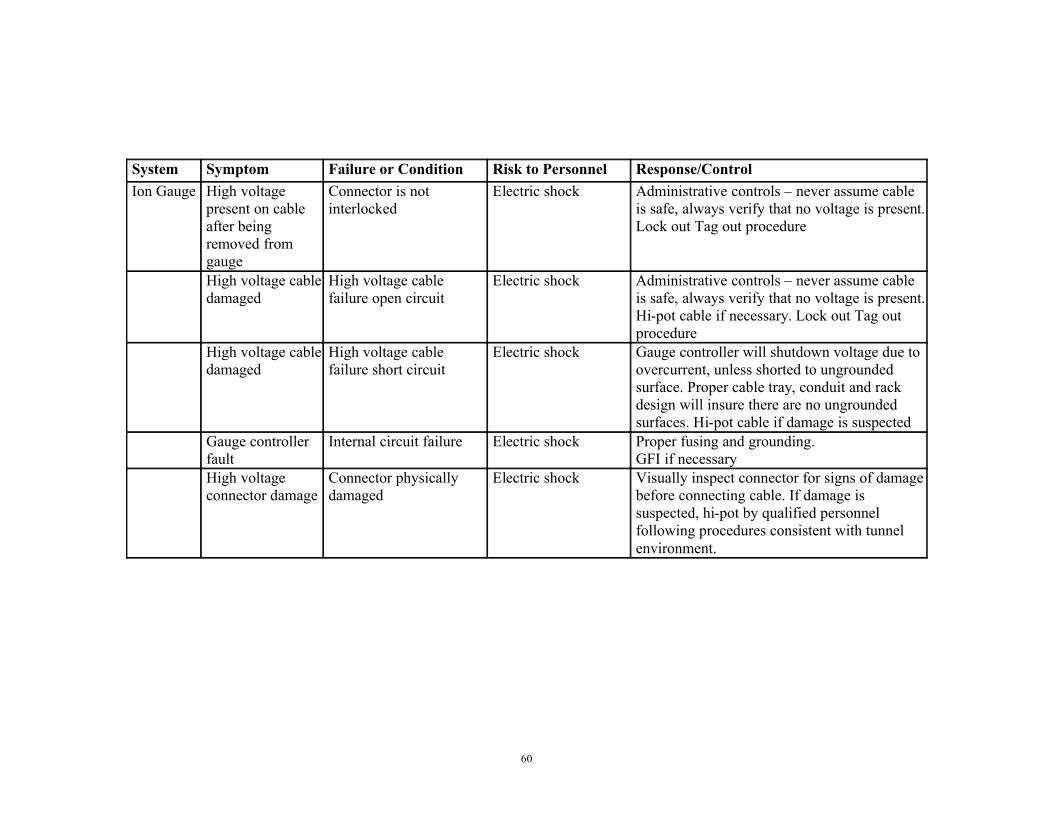
60
System Symptom Failure or Condition Risk to Personnel Response/ControlIon Gauge High voltage
present on cable after being removed from gauge
Connector is not interlocked
Electric shock Administrative controls – never assume cable is safe, always verify that no voltage is present. Lock out Tag out procedure
High voltage cable damaged
High voltage cable failure open circuit
Electric shock Administrative controls – never assume cable is safe, always verify that no voltage is present. Hi-pot cable if necessary. Lock out Tag out procedure
High voltage cable damaged
High voltage cable failure short circuit
Electric shock Gauge controller will shutdown voltage due to overcurrent, unless shorted to ungrounded surface. Proper cable tray, conduit and rack design will insure there are no ungrounded surfaces. Hi-pot cable if damage is suspected
Gauge controller fault
Internal circuit failure Electric shock Proper fusing and grounding.GFI if necessary
High voltage connector damage
Connector physically damaged
Electric shock Visually inspect connector for signs of damage before connecting cable. If damage is suspected, hi-pot by qualified personnel following procedures consistent with tunnel environment.
61
6 Environmental, Safety, and Health
6.1 Design DetailsThroughout the design process, XVTS components have been continually evaluated for safety in
relation to every phase of LCLS work, including design, transportation, installation, testing, operation, and maintenance. This evaluation process is ongoing. The following is a brief description of design safety considerations in LLNL Integration Worksheet #12920 LCLS X-Ray Tunnel Vacuum Transport System [Appendix D]:
1. Seismic stability of the vacuum system has been documented in a formal, peer-reviewed engineering document, and designed based on Specification for Seismic Design of Buildings, Structures, Equipment and Systems at the Stanford Linear Accelerator Center. SLAC-1-720-0A24E-002. The design has been approved by the SLAC Earthquake Citizens Committee.
2. Electrical system components will be NRTL listed or equivalent, as determined by the LLNL AHJ testing and certification program, and will meet the requirements of the SLAC EEIP program. Procedures will be written to establish safe methods for de-energizing, installing, testing, and maintaining (including effective lock-out tag-out capability) ion pumps and their power supplies and cabling.
3. Construction, Lifting and Industrial Hazards: As a part of the design process, LLNL will consider how components can be delivered and installed into LCLS.
4. The potential for creating oxygen deficient atmospheres will be considered.5. Fire Hazard: Equipment will be designed to limit the amount of combustibles in the
underground areas, and to avoid interference with the tunnel fire suppression system. Cables and other potentially combustible materials will meet LCLS fire prevention requirements.
6. As a backup to proper design and operating procedures, gas and vacuum system components will be protected from overpressure by relief valves.
7. The planned arrangement of equipment will take into consideration the need for emergency egress, and the need to access critical equipment or operating stations (crash buttons etc.).
8. The effects of radiation on personnel and equipment will be evaluated for normal, emergency, and maintenance operations.
9. LLNL will anticipate quantities of hazardous materials and pollutants that will be part of, or used by, LCLS components. This will allow implementation of industrial hygiene controls and proper documentation of environmental regulatory compliance.
6.2 ES&H PolicyAll work will be done in accordance with LLNL ES&H policies. These policies are addressed in
the LLNL “Health and Safety Manual” and the “Environmental Protection Handbook”. LLNL ES&H policies implement U.S. Department of Energy orders to comply with all local, state, and federal regulations. These policies are carried out in accordance with LLNL’s Integrated Safety Management program using and Integrated Worksheet. Furthermore, all work performed by LLNL employees at

62
SLAC will be in accordance with SLAC safety rules, and all LLNL safety documentation for LCLS will be written with the goal of meeting SLAC documentation requirements.
LLNL IWS #12920 “LCLS X-Ray Tunnel Vacuum Transport System” follows the five steps of the LLNL Integrated Safety Management Program:
1. Define the scope of work: LLNL LCLS management has written a detailed description of the design, fabrication, installation, operation, maintenance, and servicing of the X-Ray Vacuum Transport System (XVTS). The scope of work additionally identifies the individuals assigned to the activity, where each task will be performed, the source of funding, the authorization chain, and required reviewers.
2. Analyze the Hazards: The IWS Responsible Individual (RI), the workers listed on the IWS roster, and the LLNL ES&H Team reviews the proposed work to identify potential safety, regulatory, and environmental hazards. Each hazard is separately described in the IWS
3. Develop/Implement Controls: The RI, workers, and ES&H disciplines (industrial safety engineer, a fire protection engineer, health physicist, industrial hygienist) work together to determine and document how each of the hazards identified in step 2 can be mitigated. For the XVTS, this includes the standards that must be complied with to ensure adequate seismic design, electrical codes and LCLS wiring standards, procedures for installing and testing ion pumps, calculations to determine if inert gas use could cause an asphyxiation hazard, etc.
4. Perform the Work: Once each ES&H discipline, the ES&H team leader, the RI and the authorizing individual signify their approval (by changing their light on the IWS from red to green) that all hazards have been identified and addressed, work is allowed to proceed under the conditions of the IWS.
5. Feedback and improve: The process of designing, fabricating, transporting, installing, testing, operating, and maintaining LCLS vacuum system components will change significantly over the next four years. Initially the IWS will call for generalized controls such as procedures that will have to be written, or hazards that will have to be analyzed before certain actions can be performed. As new information becomes available, or when changes are made to the design or procedures, the IWS is updated by the RI, causing an automatic e-mail message to be sent to all LLNL LCLS workers and managers, describing the details of the change. It is expected that the IWS will change daily during some periods, and weekly in others. Major changes that affect safety will be reviewed by the ES&H Team and LLNL LCLS management (major changed to an IWS cause the reviewer’s electronic lights to change from green to yellow, signifying that they must re-review the hazards and controls). Minor changes such as clarification, changes to the personnel roster, and other details that do not have a significant safety impact can be performed by the RI made additional review. This allows the RI to continually adjust the IWS to incorporate the best available information.
63
6.3 Design Details & Potential Hazards
During certain maintenance operations, some or all of the sections of the XVTS vacuum system may be purged with a positive pressure of dry N2 gas to prevent contamination from the atmosphere from reaching the interior surfaces of the vacuum system. LLNL is responsible for the pressure safety of the XVTS system. Each section will have a valve to vent the system to atmosphere pressure. It is recommended that clean, dry nitrogen be used to vent the system and to continuously purge the system while it is open so that the interior surfaces of the vacuum remain as clean and moisture free as possible. A low pressure regulator is required to prevent over-pressurization of the system. Burst discs of the proper relief pressure will be installed on all sections in the event of over-pressurization. Since nitrogen displaces oxygen, the facility will have to determine if a confined space exists and provide the appropriate controls for such a hazard. Other than the pressure safety of the vacuum vessels, the operation of a vacuum system poses few hazards. The obvious hazards are generally associated with the operation of the vacuum pumps and electromechanical equipment such as valves.
The ion pumps selected for the XVTS vacuum system requires up to 7000 VDC. The ion pump controller that has been selected for the XVTS vacuum system is the Gamma Digital Multiple Pump Controller (MPC). The ion pump controller can provide up to 100 mA in a short circuit, but the ion pumps are generally operated in the micro-amp range. The high voltage connector on the back of the MPC is a Kings 10kV SHV.
The connector on the ion pump will either be a Varian StarCell type connector or a Gamma Safe Conn type connector. The type of connector is to be selected by the LCLS.
The ion pump controller will be mounted in an equipment rack that has a lockable rear panel to prevent unauthorized or accidental removal of the high voltage cable from the rear panel connector on the ion pump controller. High voltage safety will require proper administrative control of these keys.
The turbomolecular pump controller outputs a 56 VAC, 3 phase, 700 Hz signal to the pump. The turbomolecular pump controller can detect an open circuit and will not output a voltage under such a condition. There is also over current protection that will also shut down the output voltage if the operating current of the pump is abnormally high or in the event of a short circuit.
The scroll pump operates on 120 VAC, single phase, 60 Hz and will be controlled by a Nationally Recognized Testing Laboratory approved motor control circuit with thermal overload protection.
The vacuum valves will be electropneumatic and require compressed air up to 125 psi. The 125 psi compressed air system will comply with Chapter 32 of the LLNL “Health and Safety Manual”, “Pressure Safety”, which is in accordance with all applicable ASME and DOT codes and regulations. Failure in the compressed air lines are usually the result of a damaged hose or improperly installed pneumatic fitting. Hoses and fittings of the proper rating should be inspected after installation and also periodically afterwards. The solenoids on the electropneumatic valves will be 24 VDC, which is classified as low voltage.
The vacuum valves will be normally closed valves, so that in the event of a power failure, the valves will close and isolate the vacuum if the compressed air system has an adequate reservoir.
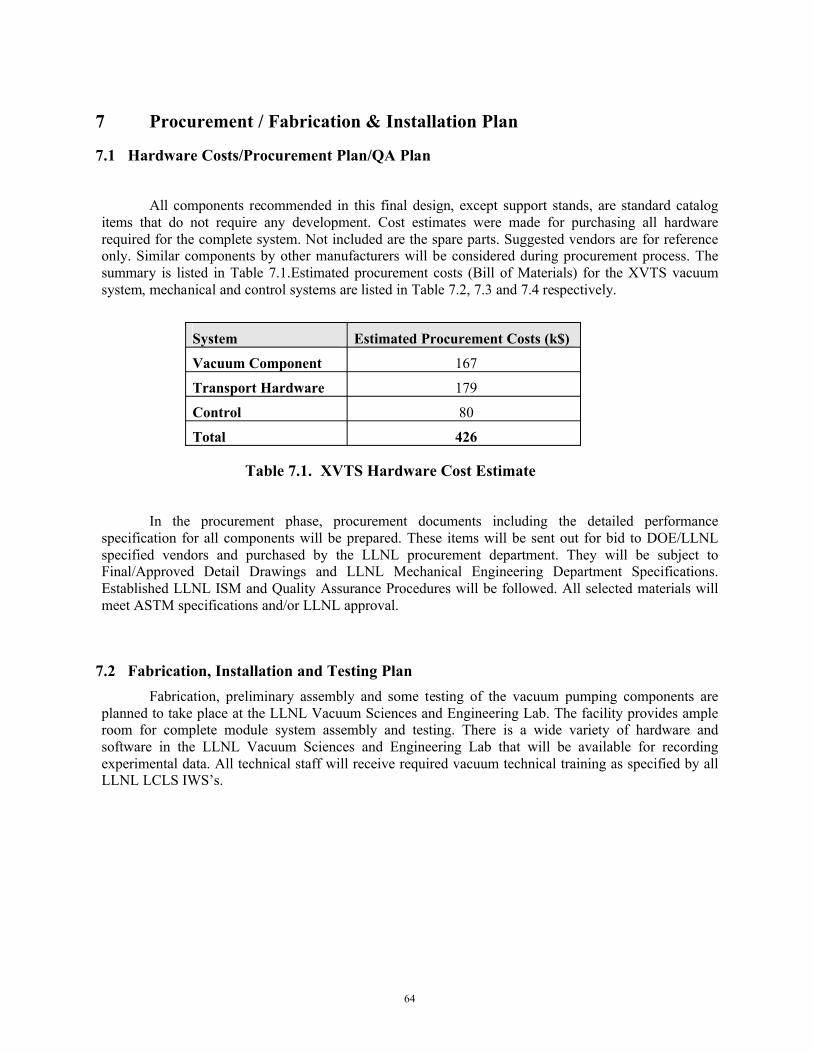
64
7 Procurement / Fabrication & Installation Plan
7.1 Hardware Costs/Procurement Plan/QA Plan
All components recommended in this final design, except support stands, are standard catalog items that do not require any development. Cost estimates were made for purchasing all hardware required for the complete system. Not included are the spare parts. Suggested vendors are for reference only. Similar components by other manufacturers will be considered during procurement process. The summary is listed in Table 7.1.Estimated procurement costs (Bill of Materials) for the XVTS vacuumsystem, mechanical and control systems are listed in Table 7.2, 7.3 and 7.4 respectively.
System Estimated Procurement Costs (k$)
Vacuum Component 167
Transport Hardware 179
Control 80
Total 426
Table 7.1. XVTS Hardware Cost Estimate
In the procurement phase, procurement documents including the detailed performance specification for all components will be prepared. These items will be sent out for bid to DOE/LLNL specified vendors and purchased by the LLNL procurement department. They will be subject to Final/Approved Detail Drawings and LLNL Mechanical Engineering Department Specifications. Established LLNL ISM and Quality Assurance Procedures will be followed. All selected materials will meet ASTM specifications and/or LLNL approval.
7.2 Fabrication, Installation and Testing PlanFabrication, preliminary assembly and some testing of the vacuum pumping components are
planned to take place at the LLNL Vacuum Sciences and Engineering Lab. The facility provides ample room for complete module system assembly and testing. There is a wide variety of hardware and software in the LLNL Vacuum Sciences and Engineering Lab that will be available for recording experimental data. All technical staff will receive required vacuum technical training as specified by all LLNL LCLS IWS’s.
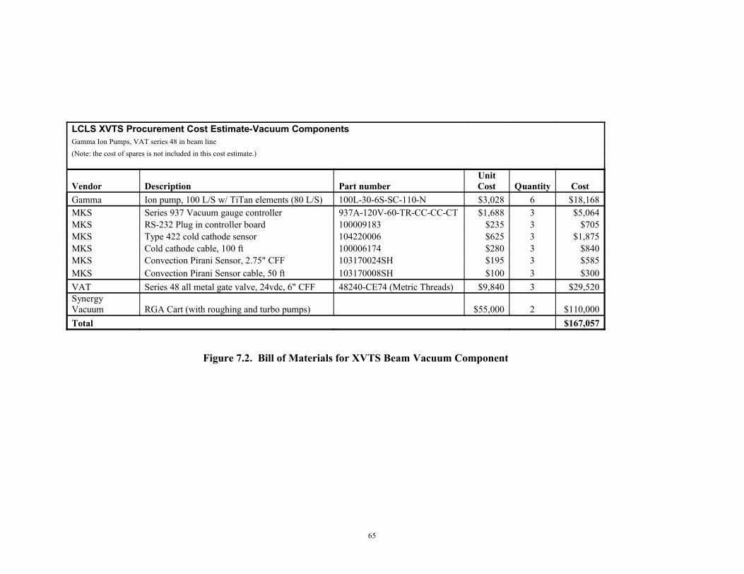
65
LCLS XVTS Procurement Cost Estimate-Vacuum ComponentsGamma Ion Pumps, VAT series 48 in beam line(Note: the cost of spares is not included in this cost estimate.)
Vendor Description Part numberUnit Cost Quantity Cost
Gamma Ion pump, 100 L/S w/ TiTan elements (80 L/S) 100L-30-6S-SC-110-N $3,028 6 $18,168MKS Series 937 Vacuum gauge controller 937A-120V-60-TR-CC-CC-CT $1,688 3 $5,064MKS RS-232 Plug in controller board 100009183 $235 3 $705MKS Type 422 cold cathode sensor 104220006 $625 3 $1,875MKS Cold cathode cable, 100 ft 100006174 $280 3 $840MKS Convection Pirani Sensor, 2.75" CFF 103170024SH $195 3 $585MKS Convection Pirani Sensor cable, 50 ft 103170008SH $100 3 $300VAT Series 48 all metal gate valve, 24vdc, 6" CFF 48240-CE74 (Metric Threads) $9,840 3 $29,520Synergy Vacuum RGA Cart (with roughing and turbo pumps) $55,000 2 $110,000Total $167,057
Figure 7.2. Bill of Materials for XVTS Beam Vacuum Component
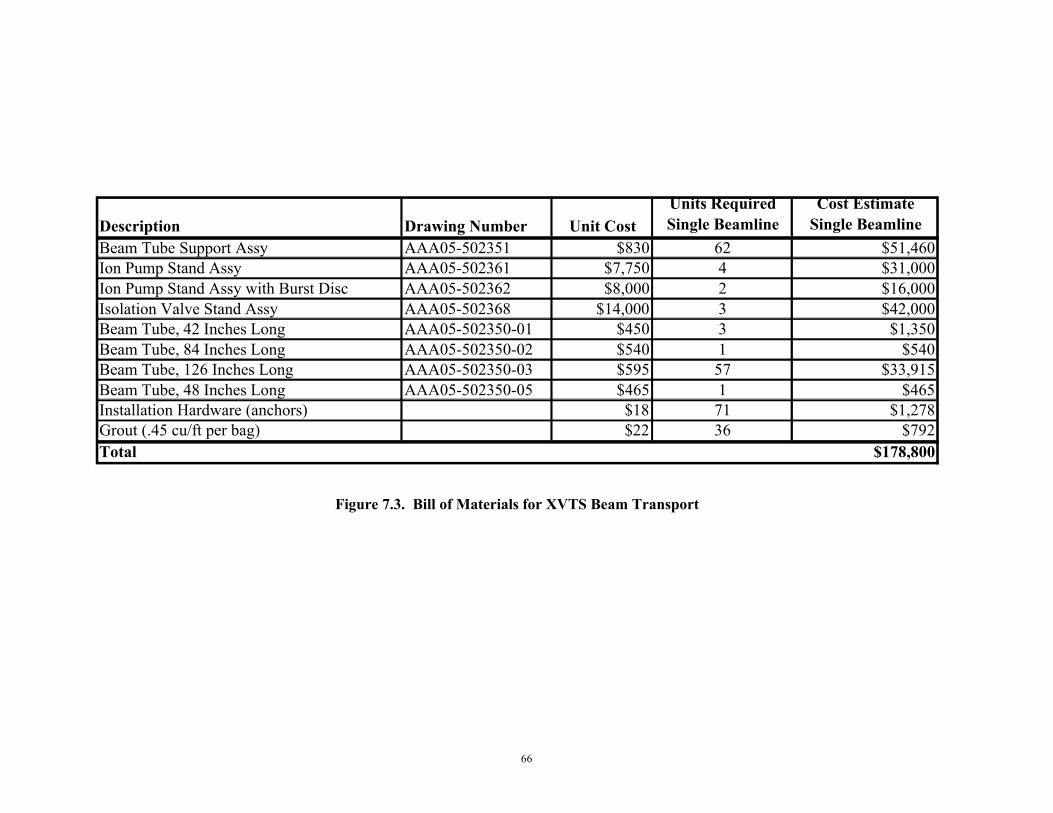
66
Description Drawing Number Unit CostUnits Required Single Beamline
Cost Estimate Single Beamline
Beam Tube Support Assy AAA05-502351 $830 62 $51,460Ion Pump Stand Assy AAA05-502361 $7,750 4 $31,000Ion Pump Stand Assy with Burst Disc AAA05-502362 $8,000 2 $16,000Isolation Valve Stand Assy AAA05-502368 $14,000 3 $42,000Beam Tube, 42 Inches Long AAA05-502350-01 $450 3 $1,350Beam Tube, 84 Inches Long AAA05-502350-02 $540 1 $540Beam Tube, 126 Inches Long AAA05-502350-03 $595 57 $33,915Beam Tube, 48 Inches Long AAA05-502350-05 $465 1 $465Installation Hardware (anchors) $18 71 $1,278Grout (.45 cu/ft per bag) $22 36 $792Total $178,800
Figure 7.3. Bill of Materials for XVTS Beam Transport
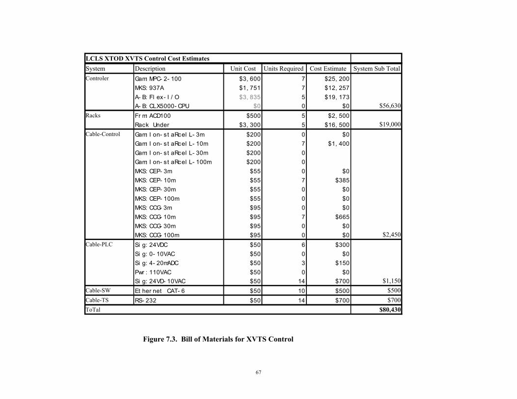
67
Figure 7.3. Bill of Materials for XVTS Control
LCLS XTOD XVTS Control Cost EstimatesSystem Description Unit Cost Units Required Cost Estimate System Sub TotalControler Gam: MPC- 2- 100 $3, 600 7 $25, 200
MKS: 937A $1, 751 7 $12, 257A- B: Fl ex- I / O $3, 835 5 $19, 173A- B: CLX5000- CPU $0 0 $0 $56,630
Racks Fr m: ACD100 $500 5 $2, 500Rack Under $3, 300 5 $16, 500 $19,000
Cable-Control Gam: I on- st aRcel L- 3m $200 0 $0Gam: I on- st aRcel L- 10m $200 7 $1, 400Gam: I on- st aRcel L- 30m $200 0Gam: I on- st aRcel L- 100m $200 0MKS: CEP- 3m $55 0 $0MKS: CEP- 10m $55 7 $385MKS: CEP- 30m $55 0 $0MKS: CEP- 100m $55 0 $0MKS: CCG- 3m $95 0 $0MKS: CCG- 10m $95 7 $665MKS: CCG- 30m $95 0 $0MKS: CCG- 100m $95 0 $0 $2,450
Cable-PLC Si g: 24VDC $50 6 $300Si g: 0- 10VAC $50 0 $0Si g: 4- 20mADC $50 3 $150Pwr : 110VAC $50 0 $0Si g: 24VD- 10VAC $50 14 $700 $1,150
Cable-SW Et her net CAT- 6 $50 10 $500 $500Cable-TS RS- 232 $50 14 $700 $700ToTal $80,430

68
Fabrication of all vacuum components must comply with the specifications listed below and their front pages are attached in Appendix A.
1. MEL95-001818-00, “Fabrication and Handling of Components for Ultra-High Vacuum Environment”, Mechanical Engineering Department, LLNL, University of California.
2. ENC-93-910-REV 01, “Cleaning Stainless Steel Alloy Components”, Mechanical Engineering Department, LLNL, University of California.
3. ENC-93-912-REV 01, “Cleaning Copper and Copper Alloy Components”, Mechanical Engineering Department, LLNL, University of California.
4. MEL95-001817-00, "Welding of Stainless Steel components of Ultra-High Vacuum Environment", Mechanical Engineering Department, LLNL, University of California.
Preserving the cleanliness of the components during installation is essential in order to meet the required pressures in a timely manner. It is recommended that the LCLS facility develop a written installation procedure for all vacuum systems for training technical staff.
7.3 Facility Interface
The interfaces between the LCLS XTOD and Conventional Facilities Systems have been defined in “ICD 1.1-508” and LCLS Room Data Sheet Section “5.7- X-ray Transport & Diagnostics Tunnel”. These interfaces occur all along the physical expanse of the Front End Enclosure, Near Experimental Hall, Tunnel, Far Experimental Hall, and surface Equipment Shelters. CF provides the beamline housing structures in which the XTOD components are mounted. CF also provides all cable trays, water headers, air headers, process and purge gas headers, exhaust system headers, convenience outlets, lighting, power distribution for electrical equipment racks and XTOD components, and HVAC as required for equipment in the FEE, Tunnel, and NEH. CF also upgrades utilities as required in existing housings and support buildings as required for the XTOD beamline and controls.
The XTOD System installs components and systems within the structures provided by Conventional Facilities. The interface varies with type of component. XTOD is responsible for installing the cable plant into cable trays installed by CF. CF installs anchors, per XTOD specifications, in order to mount beamline components and equipment. XTOD is responsible for installing racks in equipment shelters and FEE, Tunnel, NEH, and FEH locations provided by CF. CF provides network, power distribution and ground connections to the process racks. XTOD will specify the power requirement. CF provides compressed air, process and purge gas, and exhaust system headers with valves at locations specified by XTOD. XTOD provides specifications to CF on, internal enclosure dimensions, cable tray dimensions and routing and gas, power, temperature and humidity requirements. Shielding requirements will be provided by the SLAC Radiation Physics department based on electron beam requirements. XTOD also requires review of the implementation of LOTO and Fire Protection/Life Safety design in the power distribution.
Mechanical Requirements – Mechanical interfaces are at the housing floor for beamline devices, housing floor for process equipment rack mounting, housing walls for beam transport pipes, power connection at each process equipment rack for power distribution, cable tray for cable plant installation,
69
nipples at valves for water distribution and nipples at valves for air, process, and purge gas distribution, and trunk headers for exhaust systems.
Fluid Requirements – Compressed air and exhaust headers provided by CF with valve locations specified by XTOD. XTOD provides HVAC requirements. No process and purge gas are required
Vacuum Requirements – None
Thermal Requirements – The enclosure provided by CF will form a thermally controlled volume for the FEE and the NEH hutches. The tunnel has no requirement.
RF Requirements – None
Electrical Requirements – Cabling providing power to distribution panels and beamline in the FEE, NEH, Tunnel, and FEH will be installed by CF. CF to provide certified electrical ground connections throughout the FEE, NEH, Tunnel, and FEH. Cabling from process racks to beamline equipment will be installed by XTOD (or Controls Department). All cable trays are to be installed by CF. XTOD will provide cable tray dimensions and routing diagrams for tray to XTOD components and systems. Cabling requirements to conform to the LCLS specification, “1-101 LCLS Cable Specifications”.
Power Requirements – CF to provide power to distribution panels. CF will also provide convenience outlets and welding power outlets. XTOD provided power requirements. The following CF power design meets the required XTOD specification:
• Three 480v, 45kva stepdown isolation transformers supply 208vac, 3 phase, 125a power to branch panel boards servicing the racks.
• Three 480vac branch panel boards provide service to three 100a welder outlets along the tunnel north wall.
• 120vac and 3 phase 208vac receptacles are distributed along the north and south walls for utility service. MO boxes will be installed.
The LCLS grounding plan is sufficient for XTOD. XTOD will interface per LCLS grounding plan standards. No clean power is required.
Signal Requirements – XTOD will provide signals from requisite XTOD systems to the PPS to turn off housing lights and power to hazards. CF will provide networking for XTOD controls.
Radiation Requirements – CF to provide housing wall thickness and geometry to meet radiation shielding. Shielding requirements will be provided by the SLAC Radiation Physics department based on electron beam requirements. Radiation shielding to conform to the LCLS specification, “1.9-100 Shielding requirements for the LCLS Project”.
Environmental Requirements – CF to provide air-conditioning in FEE and NEH. The tunnel section will not be actively controlled and will be ventilated during personnel occupancy using upstream (FEE) and downstream (FEH) HVAC systems
Other Requirements – None.
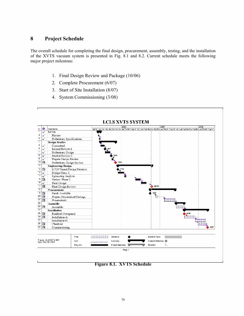
70
8 Project Schedule
The overall schedule for completing the final design, procurement, assembly, testing, and the installation of the XVTS vacuum system is presented in Fig. 8.1 and 8.2. Current schedule meets the following major project milestone:
1. Final Design Review and Package (10/06)2. Complete Procurement (6/07)3. Start of Site Installation (8/07)4. System Commissioning (3/08)
Figure 8.1. XVTS Schedule
71
9 Summary
The final design of XVTS system is completed. The major subjects presented in this report are:
1. Design of the complete system.2. System analysis results.3. ES&H issues and plan.4. Project cost estimates and schedule.
All deliverables planned in the final design phase for XVTS system is presented herein. It is shown that the designed system:
1. Is consistent with the Engineering Specifications of the XVTS system.2. Is a robust and redundant system capable of providing the required vacuum level
for XVTS operation with comfortable margin.3. Is compliant with ES&H requirements.4. Can be procured and fabricated with standard catalog items at reasonable costs, and meeting
the LCLS schedule.
72
10 References
1. “XVTX Preliminary Design Report”; UCRL-TR-217054 ; 11/9/052. “XVTS PDR Review Report” – Appendix A3. LCLS Baseline Change Request BCR-XT-8; January 20064. “LCLS XTOD Configuration DWG XRAY TNL”, AAA05-502343-AA 5/30/065. PRD- “Physics Requirements for the LCLS X-Ray Transport and Diagnostics”, LCLS Physics
Requirements Document # 1.5-001; 5/14/046. PRD Document, “Physics Requirements for the XTOD Mechanical-Vacuum Systems”, LCLS
Physics Requirements Document # 1.5-002; 2/15/067. ESD -“ LCLS Mechanical Vacuum Specifications”; LCLS ESD # 1.1-302; 7/26/058. ESD -“XTOD-XVTS”, LCLS Engineering Specifications Document # 1.5-100; 2/24/069. “Electron and X-Ray Beam Stability Estimates in the LCLS” LCLS Physics Requirements
Document # 1.1-012 ;Feb. 6, 200610. “SLAC Vacuum Department Guidelines for Vacuum Systems”; SLAC-I-007-12004-001 R1;4/17/0311. ESD -“LCLS Injector & Linac Vacuum Pump Cart Specification”, LCLS ESD # 1.2-204; 4/4/06
73
11 Appendix
11.A XVTS PDR Review Committee Report
To: John Arthur, LCLS Photon Beam System ManagerFrom: Leif Eriksson, Chair LCLS XTOD XVTS PDR review teamSubject: LCLS Vacuum SafetyDate: November 15, 2005________________________________________________________________________
John,
Thank you and your staff for providing concise presentations and information on the progress to date of the LCLS XTOD XVTS. Consistent with DOE terminology we have outlined our observations and remarks in the following manner.
Finding – Serious issues that must be corrected before the project moves forward.
Concerns – Issues that must be corrected or have a plan for correction. ** Normally where there is a corrective action plan, there needs to be a timeline given by the project for its execution. 90 days is a routine timeline, but it may be negotiable depending on project maturity.
Opportunities for Improvement – Issues that would be best management practice to have a plan for an alternative approach identified.
Observations – Statements of the conditions that existed during the review that could be improved upon or that appeared to be just satisfactory.
Noteworthy practices – issues or practices seen during the review sufficient for special recognition
I feel that the observations the review team made will add strength and value to your project and we remain committed to the successful completion of the LCLS XTOD XVTS project. If we can help further, please don’t hesitate to contact us.
Leif [email protected]
Summary:
A Preliminary Design Report was issued on November 9, 2005 by New Technologies Engineering Division, Lawrence Livermore National Laboratory for the LCLS XTOD Tunnel Vacuum System (XVTS) and presented in a subsequent Preliminary Design Review held at SLAC on November 09, 2005.
The scope of the XVTS is to design a vacuum system to enclose the x-ray beam line from the Near Hall to the Far Hall, a distance of ~718 feet. The vacuum system consists of 4” diameter SST pipes 10’ long, Conflat flanges, with vacuum pumps distributed along the length to maintain an average pressure of 10-6 Torr. The vacuum system does not contain optical elements or precision mechanisms, and as designed will function as a drift section for X-rays traversing the distance between experimental halls. The design as presented allowed for an almost totally automated pump-down scheme with interface to an Epics control system where operators would monitor and trouble shoot this vacuum system via computer as the ion pump and ion gauge controllers will be located inside the X-ray tunnel.
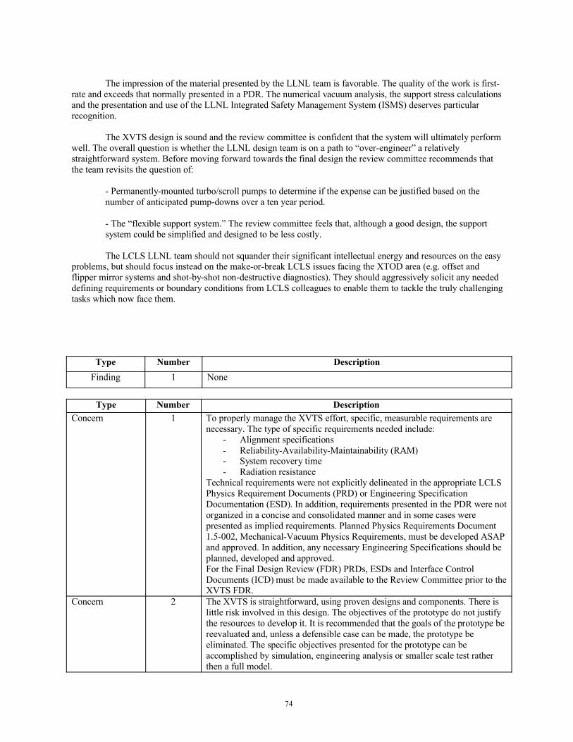
74
The impression of the material presented by the LLNL team is favorable. The quality of the work is first-rate and exceeds that normally presented in a PDR. The numerical vacuum analysis, the support stress calculations and the presentation and use of the LLNL Integrated Safety Management System (ISMS) deserves particular recognition.
The XVTS design is sound and the review committee is confident that the system will ultimately perform well. The overall question is whether the LLNL design team is on a path to “over-engineer” a relatively straightforward system. Before moving forward towards the final design the review committee recommends that the team revisits the question of:
- Permanently-mounted turbo/scroll pumps to determine if the expense can be justified based on the number of anticipated pump-downs over a ten year period.
- The “flexible support system.” The review committee feels that, although a good design, the support system could be simplified and designed to be less costly.
The LCLS LLNL team should not squander their significant intellectual energy and resources on the easy problems, but should focus instead on the make-or-break LCLS issues facing the XTOD area (e.g. offset and flipper mirror systems and shot-by-shot non-destructive diagnostics). They should aggressively solicit any needed defining requirements or boundary conditions from LCLS colleagues to enable them to tackle the truly challenging tasks which now face them.
Type Number DescriptionFinding 1 None
Type Number DescriptionConcern 1 To properly manage the XVTS effort, specific, measurable requirements are
necessary. The type of specific requirements needed include:- Alignment specifications- Reliability-Availability-Maintainability (RAM)- System recovery time- Radiation resistance
Technical requirements were not explicitly delineated in the appropriate LCLS Physics Requirement Documents (PRD) or Engineering Specification Documentation (ESD). In addition, requirements presented in the PDR were not organized in a concise and consolidated manner and in some cases were presented as implied requirements. Planned Physics Requirements Document 1.5-002, Mechanical-Vacuum Physics Requirements, must be developed ASAP and approved. In addition, any necessary Engineering Specifications should be planned, developed and approved.For the Final Design Review (FDR) PRDs, ESDs and Interface Control Documents (ICD) must be made available to the Review Committee prior to the XVTS FDR.
Concern 2 The XVTS is straightforward, using proven designs and components. There is little risk involved in this design. The objectives of the prototype do not justify the resources to develop it. It is recommended that the goals of the prototype be reevaluated and, unless a defensible case can be made, the prototype be eliminated. The specific objectives presented for the prototype can be accomplished by simulation, engineering analysis or smaller scale test rather then a full model.
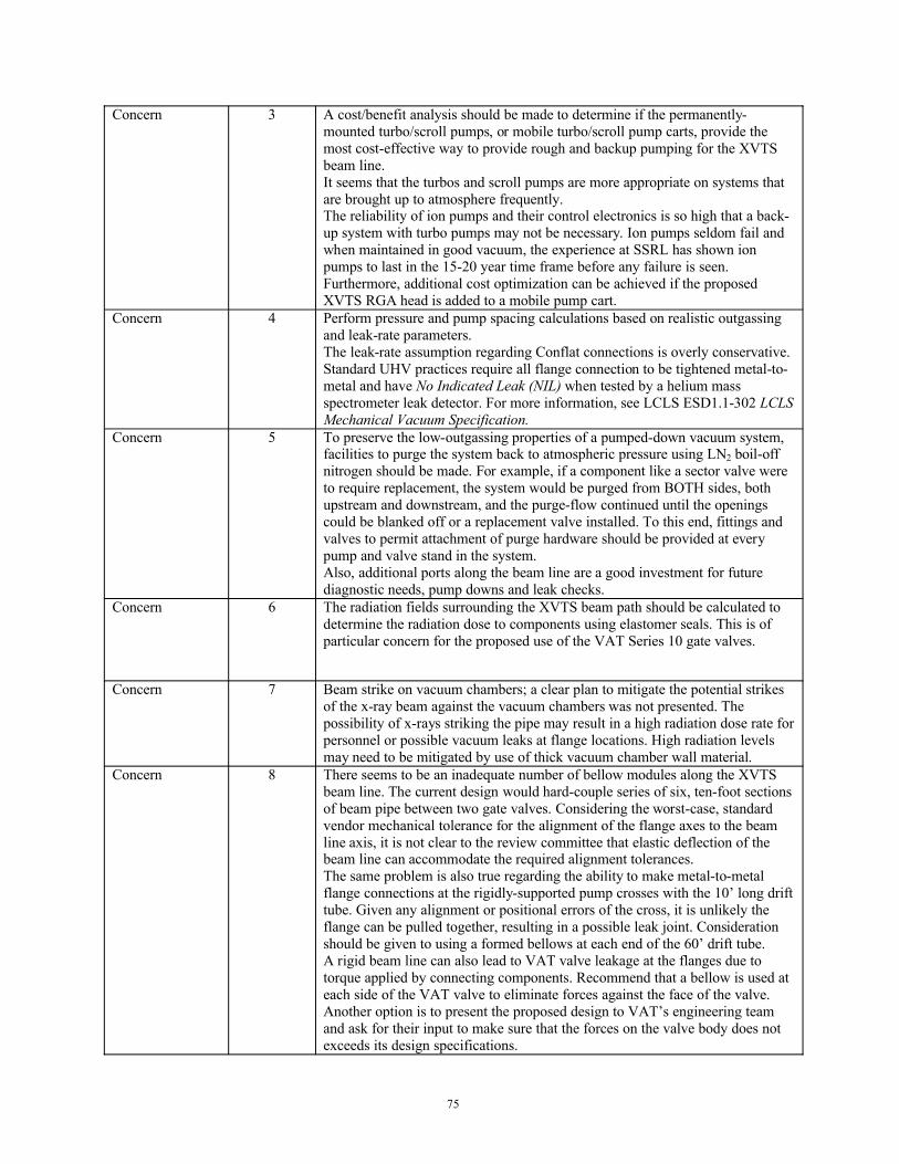
75
Concern 3 A cost/benefit analysis should be made to determine if the permanently-mounted turbo/scroll pumps, or mobile turbo/scroll pump carts, provide the most cost-effective way to provide rough and backup pumping for the XVTS beam line.It seems that the turbos and scroll pumps are more appropriate on systems that are brought up to atmosphere frequently.The reliability of ion pumps and their control electronics is so high that a back-up system with turbo pumps may not be necessary. Ion pumps seldom fail and when maintained in good vacuum, the experience at SSRL has shown ion pumps to last in the 15-20 year time frame before any failure is seen.Furthermore, additional cost optimization can be achieved if the proposed XVTS RGA head is added to a mobile pump cart.
Concern 4 Perform pressure and pump spacing calculations based on realistic outgassing and leak-rate parameters.The leak-rate assumption regarding Conflat connections is overly conservative. Standard UHV practices require all flange connection to be tightened metal-to-metal and have No Indicated Leak (NIL) when tested by a helium mass spectrometer leak detector. For more information, see LCLS ESD1.1-302 LCLS Mechanical Vacuum Specification.
Concern 5 To preserve the low-outgassing properties of a pumped-down vacuum system, facilities to purge the system back to atmospheric pressure using LN2 boil-off nitrogen should be made. For example, if a component like a sector valve were to require replacement, the system would be purged from BOTH sides, both upstream and downstream, and the purge-flow continued until the openings could be blanked off or a replacement valve installed. To this end, fittings and valves to permit attachment of purge hardware should be provided at everypump and valve stand in the system.Also, additional ports along the beam line are a good investment for future diagnostic needs, pump downs and leak checks.
Concern 6 The radiation fields surrounding the XVTS beam path should be calculated to determine the radiation dose to components using elastomer seals. This is of particular concern for the proposed use of the VAT Series 10 gate valves.
Concern 7 Beam strike on vacuum chambers; a clear plan to mitigate the potential strikes of the x-ray beam against the vacuum chambers was not presented. The possibility of x-rays striking the pipe may result in a high radiation dose rate for personnel or possible vacuum leaks at flange locations. High radiation levels may need to be mitigated by use of thick vacuum chamber wall material.
Concern 8 There seems to be an inadequate number of bellow modules along the XVTS beam line. The current design would hard-couple series of six, ten-foot sections of beam pipe between two gate valves. Considering the worst-case, standard vendor mechanical tolerance for the alignment of the flange axes to the beam line axis, it is not clear to the review committee that elastic deflection of the beam line can accommodate the required alignment tolerances.The same problem is also true regarding the ability to make metal-to-metal flange connections at the rigidly-supported pump crosses with the 10’ long drift tube. Given any alignment or positional errors of the cross, it is unlikely the flange can be pulled together, resulting in a possible leak joint. Consideration should be given to using a formed bellows at each end of the 60’ drift tube.A rigid beam line can also lead to VAT valve leakage at the flanges due to torque applied by connecting components. Recommend that a bellow is used at each side of the VAT valve to eliminate forces against the face of the valve. Another option is to present the proposed design to VAT’s engineering team and ask for their input to make sure that the forces on the valve body does not exceeds its design specifications.

76
Concern 9 With a beam line diverging to approximately half a tunnel width, no mention was made of cable routing, which presumably must drop from overhead, and be capable of HV and multi-conductor cable carrying. The installation was not a part of the CF's 20% review. Potential impacts to design and cost were not described.
Concern 10 Will a member of the LLNL team supply the details of power panel locations that are likely to be coincident with rack placements for CF, which is pending with a 12/1 due date?
Concern 11 Nothing was said about how or where the XVTS equipment will be made available for installation. Will the systems be pre-loaded at LLNL? Is the equipment shipped to the LCLS site for installation or simply shipped to SLAC receiving?
Type Number DescriptionOpportunity for Improvement
1 Some further consideration of the vacuum interface from the Transport system to components immediately upstream and downstream should be made. Particularly, if the XVTS operates at a significantly higher pressure thanadjacent vacuum systems.It may be advantageous to modify the XVTS vacuum specifications to a UHV system and thereby eliminating the need for costly differential pumping systems between the XVTS and adjacent vacuum systems.In that spirit, consideration should be given to increasing the size of the ion pumps, possibly up to 150 l/s, to allow for lower pressure capability; this may impact the stand design.The cost should be insignificant and the design flexibility will increase.
Opportunity for Improvement
2 Some future desire to make the XVTS an occupied area should be anticipatedand suitable preparations made now. These may involve over-designing the present mechanical structures to accommodate added Pb-sheet shielding, using a vacuum envelope with a thicker wall and/or assuring that double limit switches be present on future PPS devices.
Opportunity for Improvement
3 Resolve the space issue between the south wall of the XTOD tunnel and the south XVTS beam line. Currently the space is 12” as dictated by LCLS CF. The XVTS team mentioned that they prefer 18” to allow adequate space for installation and maintenance.
Opportunity for Improvement
4 The use of welded connections instead of CF flanges to reduce cost was raised at the PDR. The review committee recommends keeping the flange design which allows flexibility and ease of field installations.
Opportunity for Improvement
5 The question “Can an FEL beam strike on a closed or closing VAT Series 48 valve in this system damage the valve?” was asked during the PDR presentation but largely left unanswered. This question must be investigated and described in the XVTS Preliminary Design Report.
Opportunity for Improvement
6 An Engineering Specification Document, ESD, needs to be developed for the XVTS flexible support system. The aim for the ESD should be to reduce cost and to investigate if flexible supports are needed for the XVTS.Also, the flex supports having the adjustments at the floor level make them difficult to adjust. Consideration to move the adjustments to the top should be done if this design is used.
Opportunity for Improvement
7 Grouting stands to floor is a good and secure method, design should leave 3” gap for double nuts and aligning washers. Long Hilti anchors were used by SSRL (7/8” x 14” long) for SPEAR 3 and were readily available.
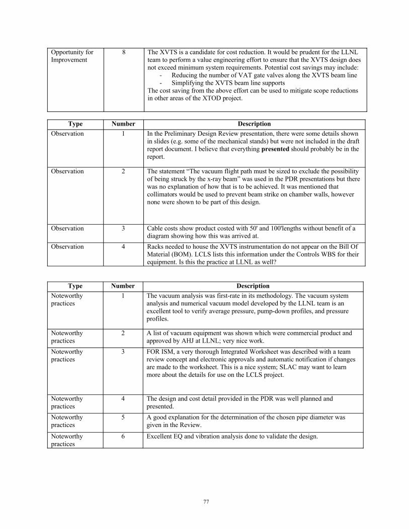
77
Opportunity for Improvement
8 The XVTS is a candidate for cost reduction. It would be prudent for the LLNLteam to perform a value engineering effort to ensure that the XVTS design does not exceed minimum system requirements. Potential cost savings may include:
- Reducing the number of VAT gate valves along the XVTS beam line- Simplifying the XVTS beam line supports
The cost saving from the above effort can be used to mitigate scope reductions in other areas of the XTOD project.
Type Number DescriptionObservation 1 In the Preliminary Design Review presentation, there were some details shown
in slides (e.g. some of the mechanical stands) but were not included in the draft report document. I believe that everything presented should probably be in the report.
Observation 2 The statement “The vacuum flight path must be sized to exclude the possibility of being struck by the x-ray beam” was used in the PDR presentations but there was no explanation of how that is to be achieved. It was mentioned that collimators would be used to prevent beam strike on chamber walls, however none were shown to be part of this design.
Observation 3 Cable costs show product costed with 50' and 100'lengths without benefit of a diagram showing how this was arrived at.
Observation 4 Racks needed to house the XVTS instrumentation do not appear on the Bill Of Material (BOM). LCLS lists this information under the Controls WBS for their equipment. Is this the practice at LLNL as well?
Type Number DescriptionNoteworthy practices
1 The vacuum analysis was first-rate in its methodology. The vacuum system analysis and numerical vacuum model developed by the LLNL team is an excellent tool to verify average pressure, pump-down profiles, and pressure profiles.
Noteworthy practices
2 A list of vacuum equipment was shown which were commercial product and approved by AHJ at LLNL; very nice work.
Noteworthy practices
3 FOR ISM, a very thorough Integrated Worksheet was described with a team review concept and electronic approvals and automatic notification if changes are made to the worksheet. This is a nice system; SLAC may want to learn more about the details for use on the LCLS project.
Noteworthy practices
4 The design and cost detail provided in the PDR was well planned and presented.
Noteworthy practices
5 A good explanation for the determination of the chosen pipe diameter was given in the Review.
Noteworthy practices
6 Excellent EQ and vibration analysis done to validate the design.
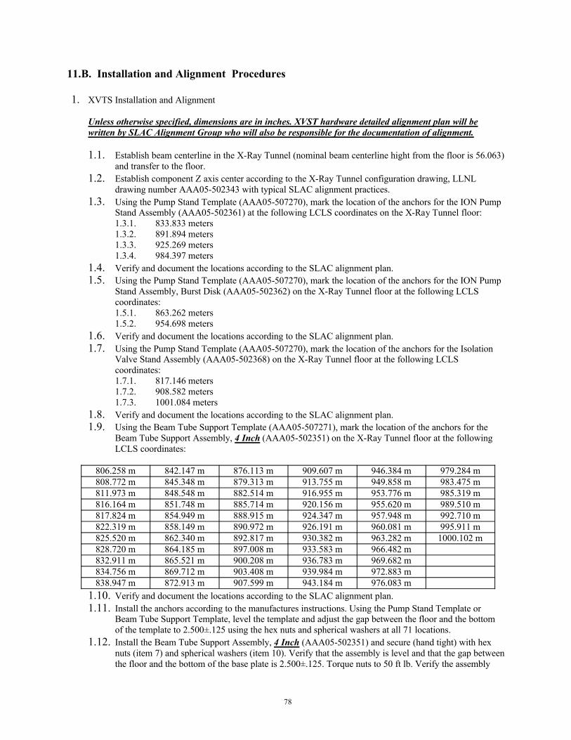
78
11.B. Installation and Alignment Procedures
1. XVTS Installation and Alignment
Unless otherwise specified, dimensions are in inches. XVST hardware detailed alignment plan will be written by SLAC Alignment Group who will also be responsible for the documentation of alignment.
1.1. Establish beam centerline in the X-Ray Tunnel (nominal beam centerline hight from the floor is 56.063) and transfer to the floor.
1.2. Establish component Z axis center according to the X-Ray Tunnel configuration drawing, LLNL drawing number AAA05-502343 with typical SLAC alignment practices.
1.3. Using the Pump Stand Template (AAA05-507270), mark the location of the anchors for the ION Pump Stand Assembly (AAA05-502361) at the following LCLS coordinates on the X-Ray Tunnel floor:1.3.1. 833.833 meters1.3.2. 891.894 meters1.3.3. 925.269 meters1.3.4. 984.397 meters
1.4. Verify and document the locations according to the SLAC alignment plan.1.5. Using the Pump Stand Template (AAA05-507270), mark the location of the anchors for the ION Pump
Stand Assembly, Burst Disk (AAA05-502362) on the X-Ray Tunnel floor at the following LCLS coordinates:1.5.1. 863.262 meters1.5.2. 954.698 meters
1.6. Verify and document the locations according to the SLAC alignment plan.1.7. Using the Pump Stand Template (AAA05-507270), mark the location of the anchors for the Isolation
Valve Stand Assembly (AAA05-502368) on the X-Ray Tunnel floor at the following LCLS coordinates:1.7.1. 817.146 meters1.7.2. 908.582 meters1.7.3. 1001.084 meters
1.8. Verify and document the locations according to the SLAC alignment plan.1.9. Using the Beam Tube Support Template (AAA05-507271), mark the location of the anchors for the
Beam Tube Support Assembly, 4 Inch (AAA05-502351) on the X-Ray Tunnel floor at the following LCLS coordinates:
806.258 m 842.147 m 876.113 m 909.607 m 946.384 m 979.284 m808.772 m 845.348 m 879.313 m 913.755 m 949.858 m 983.475 m811.973 m 848.548 m 882.514 m 916.955 m 953.776 m 985.319 m816.164 m 851.748 m 885.714 m 920.156 m 955.620 m 989.510 m817.824 m 854.949 m 888.915 m 924.347 m 957.948 m 992.710 m822.319 m 858.149 m 890.972 m 926.191 m 960.081 m 995.911 m825.520 m 862.340 m 892.817 m 930.382 m 963.282 m 1000.102 m828.720 m 864.185 m 897.008 m 933.583 m 966.482 m832.911 m 865.521 m 900.208 m 936.783 m 969.682 m834.756 m 869.712 m 903.408 m 939.984 m 972.883 m838.947 m 872.913 m 907.599 m 943.184 m 976.083 m
1.10. Verify and document the locations according to the SLAC alignment plan.1.11. Install the anchors according to the manufactures instructions. Using the Pump Stand Template or
Beam Tube Support Template, level the template and adjust the gap between the floor and the bottom of the template to 2.500±.125 using the hex nuts and spherical washers at all 71 locations.
1.12. Install the Beam Tube Support Assembly, 4 Inch (AAA05-502351) and secure (hand tight) with hex nuts (item 7) and spherical washers (item 10). Verify that the assembly is level and that the gap between the floor and the bottom of the base plate is 2.500±.125. Torque nuts to 50 ft lb. Verify the assembly
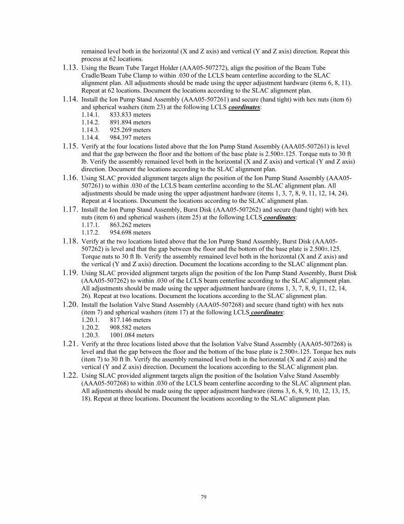
79
remained level both in the horizontal (X and Z axis) and vertical (Y and Z axis) direction. Repeat this process at 62 locations.
1.13. Using the Beam Tube Target Holder (AAA05-507272), align the position of the Beam Tube Cradle/Beam Tube Clamp to within .030 of the LCLS beam centerline according to the SLAC alignment plan. All adjustments should be made using the upper adjustment hardware (items 6, 8, 11). Repeat at 62 locations. Document the locations according to the SLAC alignment plan.
1.14. Install the Ion Pump Stand Assembly (AAA05-507261) and secure (hand tight) with hex nuts (item 6) and spherical washers (item 23) at the following LCLS coordinates:1.14.1. 833.833 meters1.14.2. 891.894 meters1.14.3. 925.269 meters1.14.4. 984.397 meters
1.15. Verify at the four locations listed above that the Ion Pump Stand Assembly (AAA05-507261) is level and that the gap between the floor and the bottom of the base plate is 2.500±.125. Torque nuts to 30 ft lb. Verify the assembly remained level both in the horizontal (X and Z axis) and vertical (Y and Z axis) direction. Document the locations according to the SLAC alignment plan.
1.16. Using SLAC provided alignment targets align the position of the Ion Pump Stand Assembly (AAA05-507261) to within .030 of the LCLS beam centerline according to the SLAC alignment plan. All adjustments should be made using the upper adjustment hardware (items 1, 3, 7, 8, 9, 11, 12, 14, 24). Repeat at 4 locations. Document the locations according to the SLAC alignment plan.
1.17. Install the Ion Pump Stand Assembly, Burst Disk (AAA05-507262) and secure (hand tight) with hex nuts (item 6) and spherical washers (item 25) at the following LCLS coordinates:1.17.1. 863.262 meters1.17.2. 954.698 meters
1.18. Verify at the two locations listed above that the Ion Pump Stand Assembly, Burst Disk (AAA05-507262) is level and that the gap between the floor and the bottom of the base plate is 2.500±.125. Torque nuts to 30 ft lb. Verify the assembly remained level both in the horizontal (X and Z axis) and the vertical (Y and Z axis) direction. Document the locations according to the SLAC alignment plan.
1.19. Using SLAC provided alignment targets align the position of the Ion Pump Stand Assembly, Burst Disk (AAA05-507262) to within .030 of the LCLS beam centerline according to the SLAC alignment plan. All adjustments should be made using the upper adjustment hardware (items 1, 3, 7, 8, 9, 11, 12, 14, 26). Repeat at two locations. Document the locations according to the SLAC alignment plan.
1.20. Install the Isolation Valve Stand Assembly (AAA05-507268) and secure (hand tight) with hex nuts (item 7) and spherical washers (item 17) at the following LCLS coordinates:1.20.1. 817.146 meters1.20.2. 908.582 meters1.20.3. 1001.084 meters
1.21. Verify at the three locations listed above that the Isolation Valve Stand Assembly (AAA05-507268) is level and that the gap between the floor and the bottom of the base plate is 2.500±.125. Torque hex nuts (item 7) to 30 ft lb. Verify the assembly remained level both in the horizontal (X and Z axis) and the vertical (Y and Z axis) direction. Document the locations according to the SLAC alignment plan.
1.22. Using SLAC provided alignment targets align the position of the Isolation Valve Stand Assembly (AAA05-507268) to within .030 of the LCLS beam centerline according to the SLAC alignment plan. All adjustments should be made using the upper adjustment hardware (items 3, 6, 8, 9, 10, 12, 13, 15, 18). Repeat at three locations. Document the locations according to the SLAC alignment plan.
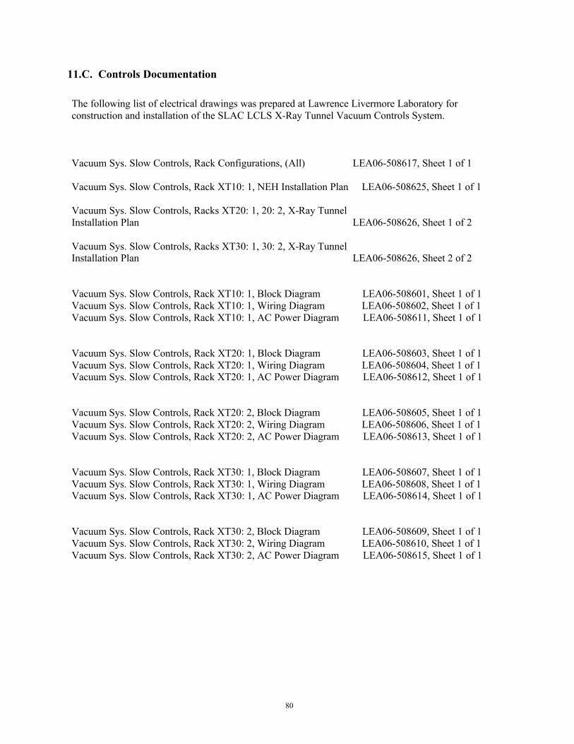
80
11.C. Controls Documentation
The following list of electrical drawings was prepared at Lawrence Livermore Laboratory for construction and installation of the SLAC LCLS X-Ray Tunnel Vacuum Controls System.
Vacuum Sys. Slow Controls, Rack Configurations, (All) LEA06-508617, Sheet 1 of 1
Vacuum Sys. Slow Controls, Rack XT10: 1, NEH Installation Plan LEA06-508625, Sheet 1 of 1
Vacuum Sys. Slow Controls, Racks XT20: 1, 20: 2, X-Ray Tunnel Installation Plan LEA06-508626, Sheet 1 of 2
Vacuum Sys. Slow Controls, Racks XT30: 1, 30: 2, X-Ray TunnelInstallation Plan LEA06-508626, Sheet 2 of 2
Vacuum Sys. Slow Controls, Rack XT10: 1, Block Diagram LEA06-508601, Sheet 1 of 1Vacuum Sys. Slow Controls, Rack XT10: 1, Wiring Diagram LEA06-508602, Sheet 1 of 1Vacuum Sys. Slow Controls, Rack XT10: 1, AC Power Diagram LEA06-508611, Sheet 1 of 1
Vacuum Sys. Slow Controls, Rack XT20: 1, Block Diagram LEA06-508603, Sheet 1 of 1Vacuum Sys. Slow Controls, Rack XT20: 1, Wiring Diagram LEA06-508604, Sheet 1 of 1Vacuum Sys. Slow Controls, Rack XT20: 1, AC Power Diagram LEA06-508612, Sheet 1 of 1
Vacuum Sys. Slow Controls, Rack XT20: 2, Block Diagram LEA06-508605, Sheet 1 of 1Vacuum Sys. Slow Controls, Rack XT20: 2, Wiring Diagram LEA06-508606, Sheet 1 of 1Vacuum Sys. Slow Controls, Rack XT20: 2, AC Power Diagram LEA06-508613, Sheet 1 of 1
Vacuum Sys. Slow Controls, Rack XT30: 1, Block Diagram LEA06-508607, Sheet 1 of 1Vacuum Sys. Slow Controls, Rack XT30: 1, Wiring Diagram LEA06-508608, Sheet 1 of 1Vacuum Sys. Slow Controls, Rack XT30: 1, AC Power Diagram LEA06-508614, Sheet 1 of 1
Vacuum Sys. Slow Controls, Rack XT30: 2, Block Diagram LEA06-508609, Sheet 1 of 1Vacuum Sys. Slow Controls, Rack XT30: 2, Wiring Diagram LEA06-508610, Sheet 1 of 1Vacuum Sys. Slow Controls, Rack XT30: 2, AC Power Diagram LEA06-508615, Sheet 1 of 1

81
11.D. LLNL IWS 12920
IWS #: WAL: IWS Status: Date Created:12920 [Not Restricted] B Proposed on 21-OCT-05 15-SEP-05
Title:
LCLS X-Ray Tunnel Vacuum Transport System
Scope of Work:
This IWS covers the design, fabrication, installation, operation, maintenance, and servicing of the X-Ray Vacuum Transport System (XVTS) which will be designed and partially fabricated at LLNL, then installed in the ~200 m tunnel connecting the Near and Far Experimental Halls of the LCLS facility at SLAC. The purpose of the XVTS is to provide 3 alternate vacuum pathways to transport the narrow (<5 mm FWHM) X-Ray (800 eV to 24000 eV) FEL radiation to any one of the 3 hutches in the Far Hall.
The XVTS consists of segments of vacuum pipe joined together to form a single beam line Approximately 20 ion-pumps, interspersed along the pipes maintain a steady state vacuum of roughly 3 x 10⁻⁶ Torr. The system includes various valves used during initial pump down and for isolation. The valves, pumps and gauges are controlled by ladder logic programmed into commercial PLC such as manufactured by Allen Bradley. A high-level EPICS control system linked to the LCLS global control software provides overall control and monitoring. The XVTS includes the pipes, pumps, stands, gauges, the associated electronics (power supplies, racks, pump controllers, PLC), and control software.
The initial pumpdown from air will be done with a pump-cart, consisting of a scroll backed turbo pump, manually attached to one or more ports designed into the XVTS for this purpose. The carts will run until the pressure is low enough to start the XVTS ion pumps, then the carts will be removed. Once pumped down to its base pressure, the XVTS will run autonomously 24 hours per day, seven days per week, during normal LCLS beam operation. The 200 m long tunnel housing the XVTS will be an unmanned area during beam operation; however it does serve as an alternative escape route from the Far Hall.
The XVTS will be designed at LLNL based on calculations performed by the LLNL LCLS group. LLNL will pre-assemble and test subassemblies such as pumping sections and develop and test the PLC and EPICS control software. When completed, assemblies and parts will be shipped from LLNL to SLAC. Some parts of the system such as the pipes and stand components may be shipped directly from the vendor to SLAC.
A mixture of SLAC and LLNL personnel will perform the installation of the hardware and software in the tunnel. The hardware will be transported to the appropriate locations in the tunnel, placed into position, and connected in place. The connections to be made in the tunnel include electrical, mechanical, vacuum, compressed air, and Ethernet.
After assembly, personnel in the tunnel will check out components and software then attach the scroll backed turbo pump carts to the system. The system will be purged, and then pumped down to base pressure with the pump carts. After the system reaches the appropriate vacuum level, ion pumps will switch in and the turbo/scroll system will be shutdown, valved off, and removed. After the initial pumpdown the system will be operated through software
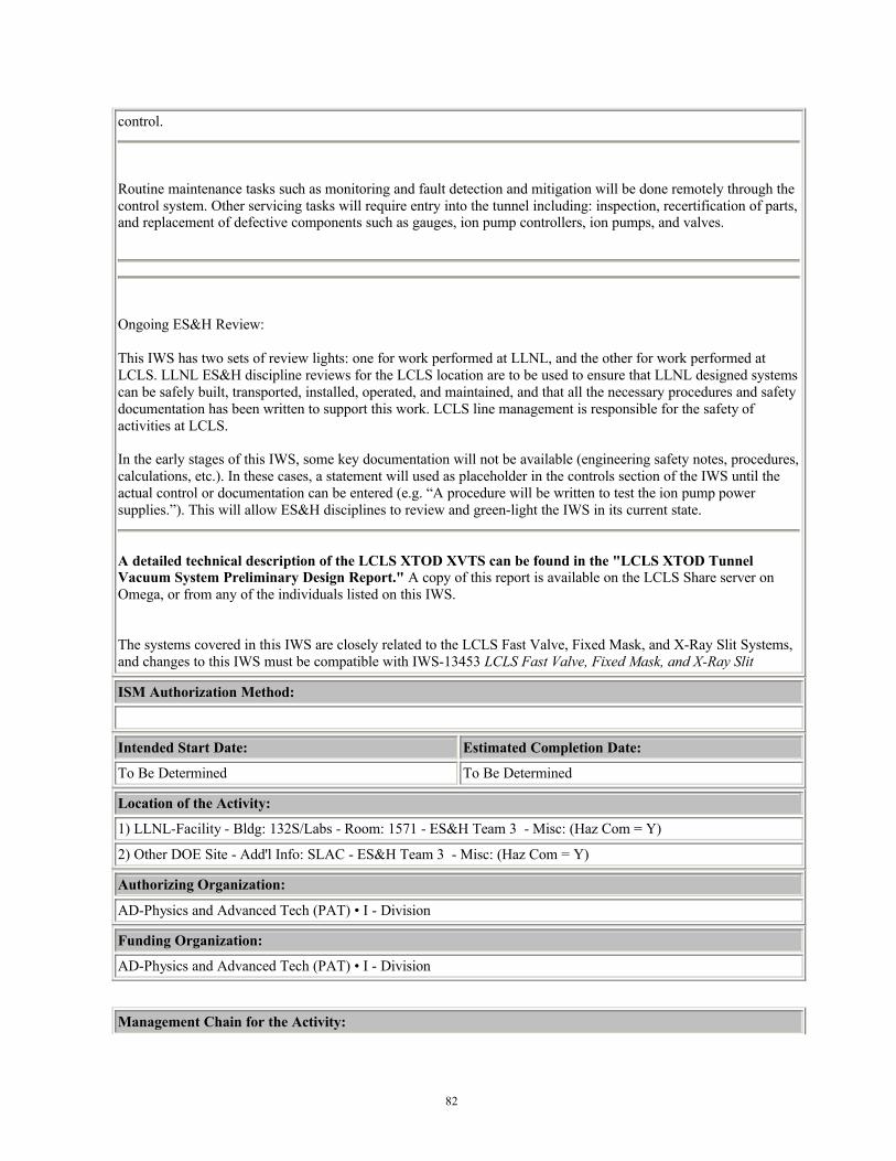
82
control.
Routine maintenance tasks such as monitoring and fault detection and mitigation will be done remotely through the control system. Other servicing tasks will require entry into the tunnel including: inspection, recertification of parts, and replacement of defective components such as gauges, ion pump controllers, ion pumps, and valves.
Ongoing ES&H Review:
This IWS has two sets of review lights: one for work performed at LLNL, and the other for work performed at LCLS. LLNL ES&H discipline reviews for the LCLS location are to be used to ensure that LLNL designed systems can be safely built, transported, installed, operated, and maintained, and that all the necessary procedures and safety documentation has been written to support this work. LCLS line management is responsible for the safety of activities at LCLS.
In the early stages of this IWS, some key documentation will not be available (engineering safety notes, procedures, calculations, etc.). In these cases, a statement will used as placeholder in the controls section of the IWS until the actual control or documentation can be entered (e.g. “A procedure will be written to test the ion pump power supplies.”). This will allow ES&H disciplines to review and green-light the IWS in its current state.
A detailed technical description of the LCLS XTOD XVTS can be found in the "LCLS XTOD Tunnel Vacuum System Preliminary Design Report." A copy of this report is available on the LCLS Share server on Omega, or from any of the individuals listed on this IWS.
The systems covered in this IWS are closely related to the LCLS Fast Valve, Fixed Mask, and X-Ray Slit Systems, and changes to this IWS must be compatible with IWS-13453 LCLS Fast Valve, Fixed Mask, and X-Ray Slit
ISM Authorization Method:
Intended Start Date: Estimated Completion Date:
To Be Determined To Be Determined
Location of the Activity:
1) LLNL-Facility - Bldg: 132S/Labs - Room: 1571 - ES&H Team 3 - Misc: (Haz Com = Y)
2) Other DOE Site - Add'l Info: SLAC - ES&H Team 3 - Misc: (Haz Com = Y)
Authorizing Organization:
AD-Physics and Advanced Tech (PAT) • I - Division
Funding Organization:
AD-Physics and Advanced Tech (PAT) • I - Division
Management Chain for the Activity:
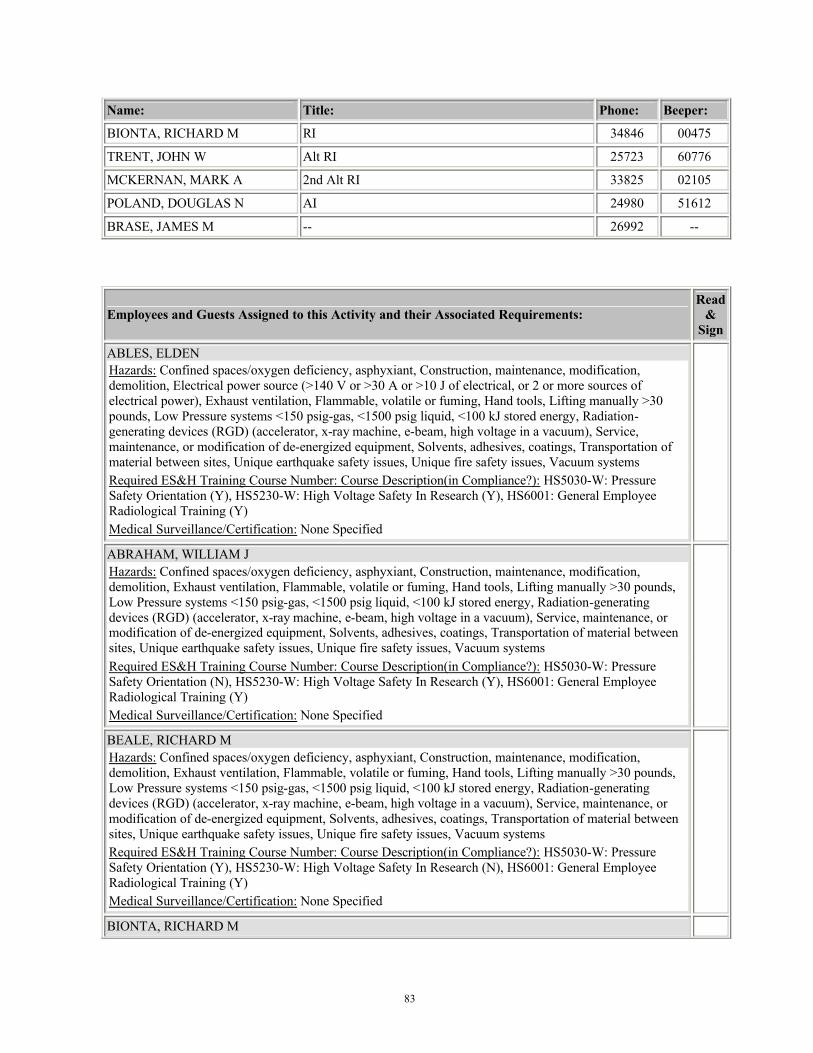
83
Name: Title: Phone: Beeper:
BIONTA, RICHARD M RI 34846 00475
TRENT, JOHN W Alt RI 25723 60776
MCKERNAN, MARK A 2nd Alt RI 33825 02105
POLAND, DOUGLAS N AI 24980 51612
BRASE, JAMES M -- 26992 --
Employees and Guests Assigned to this Activity and their Associated Requirements:Read
& Sign
ABLES, ELDEN Hazards: Confined spaces/oxygen deficiency, asphyxiant, Construction, maintenance, modification, demolition, Electrical power source (>140 V or >30 A or >10 J of electrical, or 2 or more sources of electrical power), Exhaust ventilation, Flammable, volatile or fuming, Hand tools, Lifting manually >30 pounds, Low Pressure systems <150 psig-gas, <1500 psig liquid, <100 kJ stored energy, Radiation-generating devices (RGD) (accelerator, x-ray machine, e-beam, high voltage in a vacuum), Service, maintenance, or modification of de-energized equipment, Solvents, adhesives, coatings, Transportation of material between sites, Unique earthquake safety issues, Unique fire safety issues, Vacuum systems Required ES&H Training Course Number: Course Description(in Compliance?): HS5030-W: Pressure Safety Orientation (Y), HS5230-W: High Voltage Safety In Research (Y), HS6001: General Employee Radiological Training (Y) Medical Surveillance/Certification: None Specified
ABRAHAM, WILLIAM J Hazards: Confined spaces/oxygen deficiency, asphyxiant, Construction, maintenance, modification, demolition, Exhaust ventilation, Flammable, volatile or fuming, Hand tools, Lifting manually >30 pounds, Low Pressure systems <150 psig-gas, <1500 psig liquid, <100 kJ stored energy, Radiation-generating devices (RGD) (accelerator, x-ray machine, e-beam, high voltage in a vacuum), Service, maintenance, or modification of de-energized equipment, Solvents, adhesives, coatings, Transportation of material between sites, Unique earthquake safety issues, Unique fire safety issues, Vacuum systems Required ES&H Training Course Number: Course Description(in Compliance?): HS5030-W: Pressure Safety Orientation (N), HS5230-W: High Voltage Safety In Research (Y), HS6001: General Employee Radiological Training (Y) Medical Surveillance/Certification: None Specified
BEALE, RICHARD M Hazards: Confined spaces/oxygen deficiency, asphyxiant, Construction, maintenance, modification, demolition, Exhaust ventilation, Flammable, volatile or fuming, Hand tools, Lifting manually >30 pounds, Low Pressure systems <150 psig-gas, <1500 psig liquid, <100 kJ stored energy, Radiation-generating devices (RGD) (accelerator, x-ray machine, e-beam, high voltage in a vacuum), Service, maintenance, or modification of de-energized equipment, Solvents, adhesives, coatings, Transportation of material between sites, Unique earthquake safety issues, Unique fire safety issues, Vacuum systems Required ES&H Training Course Number: Course Description(in Compliance?): HS5030-W: Pressure Safety Orientation (Y), HS5230-W: High Voltage Safety In Research (N), HS6001: General Employee Radiological Training (Y) Medical Surveillance/Certification: None Specified
BIONTA, RICHARD M
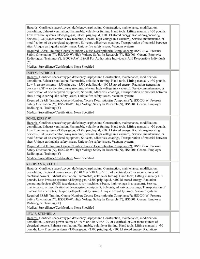
84
Hazards: Confined spaces/oxygen deficiency, asphyxiant, Construction, maintenance, modification, demolition, Exhaust ventilation, Flammable, volatile or fuming, Hand tools, Lifting manually >30 pounds, Low Pressure systems <150 psig-gas, <1500 psig liquid, <100 kJ stored energy, Radiation-generating devices (RGD) (accelerator, x-ray machine, e-beam, high voltage in a vacuum), Service, maintenance, or modification of de-energized equipment, Solvents, adhesives, coatings, Transportation of material between sites, Unique earthquake safety issues, Unique fire safety issues, Vacuum systems Required ES&H Training Course Number: Course Description(in Compliance?): HS5030-W: Pressure Safety Orientation (Y), HS5230-W: High Voltage Safety In Research (Y), HS6001: General Employee Radiological Training (Y), IS0008-AW: ES&H For Authorizing Individuals And Responsible Individuals (Y) Medical Surveillance/Certification: None Specified
DUFFY, PATRICK T Hazards: Confined spaces/oxygen deficiency, asphyxiant, Construction, maintenance, modification, demolition, Exhaust ventilation, Flammable, volatile or fuming, Hand tools, Lifting manually >30 pounds, Low Pressure systems <150 psig-gas, <1500 psig liquid, <100 kJ stored energy, Radiation-generating devices (RGD) (accelerator, x-ray machine, e-beam, high voltage in a vacuum), Service, maintenance, or modification of de-energized equipment, Solvents, adhesives, coatings, Transportation of material between sites, Unique earthquake safety issues, Unique fire safety issues, Vacuum systems Required ES&H Training Course Number: Course Description(in Compliance?): HS5030-W: Pressure Safety Orientation (Y), HS5230-W: High Voltage Safety In Research (N), HS6001: General Employee Radiological Training (Y) Medical Surveillance/Certification: None Specified
FONG, KIRBY W Hazards: Confined spaces/oxygen deficiency, asphyxiant, Construction, maintenance, modification, demolition, Exhaust ventilation, Flammable, volatile or fuming, Hand tools, Lifting manually >30 pounds, Low Pressure systems <150 psig-gas, <1500 psig liquid, <100 kJ stored energy, Radiation-generating devices (RGD) (accelerator, x-ray machine, e-beam, high voltage in a vacuum), Service, maintenance, or modification of de-energized equipment, Solvents, adhesives, coatings, Transportation of material between sites, Unique earthquake safety issues, Unique fire safety issues, Vacuum systems Required ES&H Training Course Number: Course Description(in Compliance?): HS5030-W: Pressure Safety Orientation (N), HS5230-W: High Voltage Safety In Research (N), HS6001: General Employee Radiological Training (Y) Medical Surveillance/Certification: None Specified
KISHIYAMA, KEITH I Hazards: Confined spaces/oxygen deficiency, asphyxiant, Construction, maintenance, modification, demolition, Electrical power source (>140 V or >30 A or >10 J of electrical, or 2 or more sources of electrical power), Exhaust ventilation, Flammable, volatile or fuming, Hand tools, Lifting manually >30 pounds, Low Pressure systems <150 psig-gas, <1500 psig liquid, <100 kJ stored energy, Radiation-generating devices (RGD) (accelerator, x-ray machine, e-beam, high voltage in a vacuum), Service, maintenance, or modification of de-energized equipment, Solvents, adhesives, coatings, Transportation of material between sites, Unique earthquake safety issues, Unique fire safety issues, Vacuum systems Required ES&H Training Course Number: Course Description(in Compliance?): HS5030-W: Pressure Safety Orientation (Y), HS5230-W: High Voltage Safety In Research (Y), HS6001: General Employee Radiological Training (Y) Medical Surveillance/Certification: None Specified
LEWIS, STEPHEN A Hazards: Confined spaces/oxygen deficiency, asphyxiant, Construction, maintenance, modification, demolition, Electrical power source (>140 V or >30 A or >10 J of electrical, or 2 or more sources of electrical power), Exhaust ventilation, Flammable, volatile or fuming, Hand tools, Lifting manually >30 pounds, Low Pressure systems <150 psig-gas, <1500 psig liquid, <100 kJ stored energy, Radiation-
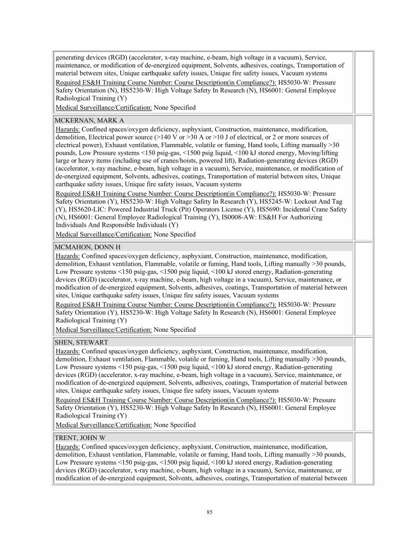
85
generating devices (RGD) (accelerator, x-ray machine, e-beam, high voltage in a vacuum), Service, maintenance, or modification of de-energized equipment, Solvents, adhesives, coatings, Transportation of material between sites, Unique earthquake safety issues, Unique fire safety issues, Vacuum systems Required ES&H Training Course Number: Course Description(in Compliance?): HS5030-W: Pressure Safety Orientation (N), HS5230-W: High Voltage Safety In Research (N), HS6001: General Employee Radiological Training (Y) Medical Surveillance/Certification: None Specified
MCKERNAN, MARK A Hazards: Confined spaces/oxygen deficiency, asphyxiant, Construction, maintenance, modification, demolition, Electrical power source (>140 V or >30 A or >10 J of electrical, or 2 or more sources of electrical power), Exhaust ventilation, Flammable, volatile or fuming, Hand tools, Lifting manually >30 pounds, Low Pressure systems <150 psig-gas, <1500 psig liquid, <100 kJ stored energy, Moving/lifting large or heavy items (including use of cranes/hoists, powered lift), Radiation-generating devices (RGD) (accelerator, x-ray machine, e-beam, high voltage in a vacuum), Service, maintenance, or modification of de-energized equipment, Solvents, adhesives, coatings, Transportation of material between sites, Unique earthquake safety issues, Unique fire safety issues, Vacuum systems Required ES&H Training Course Number: Course Description(in Compliance?): HS5030-W: Pressure Safety Orientation (Y), HS5230-W: High Voltage Safety In Research (Y), HS5245-W: Lockout And Tag (Y), HS5620-LIC: Powered Industrial Truck (Pit) Operators License (Y), HS5690: Incidental Crane Safety (N), HS6001: General Employee Radiological Training (Y), IS0008-AW: ES&H For Authorizing Individuals And Responsible Individuals (Y) Medical Surveillance/Certification: None Specified
MCMAHON, DONN H Hazards: Confined spaces/oxygen deficiency, asphyxiant, Construction, maintenance, modification, demolition, Exhaust ventilation, Flammable, volatile or fuming, Hand tools, Lifting manually >30 pounds, Low Pressure systems <150 psig-gas, <1500 psig liquid, <100 kJ stored energy, Radiation-generating devices (RGD) (accelerator, x-ray machine, e-beam, high voltage in a vacuum), Service, maintenance, or modification of de-energized equipment, Solvents, adhesives, coatings, Transportation of material between sites, Unique earthquake safety issues, Unique fire safety issues, Vacuum systems Required ES&H Training Course Number: Course Description(in Compliance?): HS5030-W: Pressure Safety Orientation (Y), HS5230-W: High Voltage Safety In Research (N), HS6001: General Employee Radiological Training (Y) Medical Surveillance/Certification: None Specified
SHEN, STEWART Hazards: Confined spaces/oxygen deficiency, asphyxiant, Construction, maintenance, modification, demolition, Exhaust ventilation, Flammable, volatile or fuming, Hand tools, Lifting manually >30 pounds, Low Pressure systems <150 psig-gas, <1500 psig liquid, <100 kJ stored energy, Radiation-generating devices (RGD) (accelerator, x-ray machine, e-beam, high voltage in a vacuum), Service, maintenance, or modification of de-energized equipment, Solvents, adhesives, coatings, Transportation of material between sites, Unique earthquake safety issues, Unique fire safety issues, Vacuum systems Required ES&H Training Course Number: Course Description(in Compliance?): HS5030-W: Pressure Safety Orientation (Y), HS5230-W: High Voltage Safety In Research (N), HS6001: General Employee Radiological Training (Y) Medical Surveillance/Certification: None Specified
TRENT, JOHN W Hazards: Confined spaces/oxygen deficiency, asphyxiant, Construction, maintenance, modification, demolition, Exhaust ventilation, Flammable, volatile or fuming, Hand tools, Lifting manually >30 pounds, Low Pressure systems <150 psig-gas, <1500 psig liquid, <100 kJ stored energy, Radiation-generating devices (RGD) (accelerator, x-ray machine, e-beam, high voltage in a vacuum), Service, maintenance, or modification of de-energized equipment, Solvents, adhesives, coatings, Transportation of material between

86
sites, Unique earthquake safety issues, Unique fire safety issues, Vacuum systems Required ES&H Training Course Number: Course Description(in Compliance?): HS5030-W: Pressure Safety Orientation (Y), HS5230-W: High Voltage Safety In Research (Y), HS6001: General Employee Radiological Training (Y), IS0008-AW: ES&H For Authorizing Individuals And Responsible Individuals (Y) Medical Surveillance/Certification: None Specified
Additional Training Information:
For all personnel working at SLAC that require unescorted access to industrial and radiologically controlled areas (e.g. Sector 20 Injector Vault, Radiological Controlled Areas):1. Employee Orientation to Environment, Safety and Health - SLAC course 2192. General Employee Radiological Training - SLAC Course 115 (LLNL employees get credit for the LLNL version of this class).3. General Electrical Safety - Course 2394. Safety Orientation for Construction (arranged through CF Project Manager)
For work at LLNL, workers who do not meet training requirements are restricted from performing tasks related to that training unless they are directly supervised by a fully qualified individual.
General Hazard Control Information:
All operations at SLAC, including LCLS, are governed by the SLAC Safety program. LLNL employees at SLAC will read and comply with all applicable SLAC safety procedures and complete required SLAC safety training. See the attached LCLS Project ES&H Plan for more details on LCLS safety at SLAC.Contacts:
SLAC LCLS Safety Manager: Mike Scharfenstein Phone: 650-926-3341 e-mail: [email protected]
LLNL LCLS Safety Liason: Richard Beale Phone: 925-422-3112 e-mail: [email protected] pager 67272
SLAC ISM Web Page: http://www-group.slac.stanford.edu/esh/isms/
LCLS Web Safety Page: https://www-ssrl.slac.stanford.edu/lcls/esh/
Hazard Descriptions and Controls:
Chemical (Hazardous Material): Flammable, volatile or fuming (Significant Environmental Aspect)
Description:
Solvents may be used to wipe-clean components at LLNL and/or SLAC. Wipe cleaning of vacuum system components is performed using absorbant paper and small amounts (up to one liter containers) of isopropyl alcohol.
Control:
Nitrile gloves and safety glasses will be worn when using the alcohol, and the area will be free of ignition sources. Except for one or two day-use bottles (of up to one liter), the alcohol will be stored in a flammable material storage locker. Secondary bottles will be labeled with the chemical's name and appropriate hazard warning(s) according to ES&H Manual Document 10.2, Section 4.2.2.
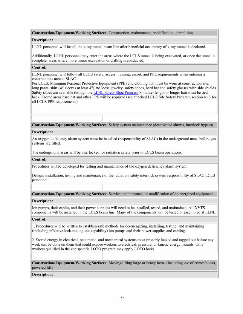
87
Construction/Equipment/Working Surfaces: Construction, maintenance, modification, demolition
Description:
LLNL personnel will install the x-ray tunnel beam line after beneficial occupancy of x-ray tunnel is declared.
Additionally, LLNL personnel may enter the areas where the LCLS tunnel is being excavated, or once the tunnel is complete, areas where more minor excavation or drilling is conducted.
Control:
LLNL personnel will follow all LCLS safety, access, training, escort, and PPE requirements when entering a constructions area at SLAC.Per LCLS: Minimum Personal Protective Equipment (PPE) and clothing that must be worn at construction site: long pants, shirt (w/ sleeves at least 4"), no loose jewelry, safety shoes, hard hat and safety glasses with side shields. Safety shoes are available through the LLNL Safety Shoe Program Shoulder length or longer hair must be tied back. I some areas hard hat and other PPE will be required (see attached LCLS Site Safety Program section 4.13 for all LCLS PPE requirements).
Construction/Equipment/Working Surfaces: Safety system maintenance (deactivated alarms, interlock bypass)
Description:
An oxygen deficiency alarm system must be installed (responsibility of SLAC) in the underground areas before gas systems are filled.
The underground areas will be interlocked for radiation safety prior to LCLS beam operations.
Control:
Procedures will be developed for testing and maintenance of the oxygen deficiency alarm system.
Design, installation, testing and maintenance of the radiation safety interlock system responsibility of SLAC LCLS personnel.
Construction/Equipment/Working Surfaces: Service, maintenance, or modification of de-energized equipment
Description:
Ion pumps, their cables, and their power supplies will need to be installed, tested, and maintained. All XVTS components will be installed in the LCLS beam line. Many of the components will be tested or assembled at LLNL.
Control:
1. Procedures will be written to establish safe methods for de-energizing, installing, testing, and maintaining (including effective lock-out tag-out capability) ion pumps and their power supplies and cabling.
2. Stored energy in electrical, pneumatic, and mechanical systems must properly locked and tagged out before any work can be done on them that could expose workers to electrical, pressure, or kinetic energy hazards. Only workers qualified in the site specific LOTO program may apply LOTO locks.
Construction/Equipment/Working Surfaces: Moving/lifting large or heavy items (including use of cranes/hoists, powered lift)
Description:
88
Vacuum system components, including stands weighing several hundred pounds, will be designed and built at LLNL, or by contractors. They will be shipped to LCLS and moved to the underground tunnel where they will be mounted to the floor.
Control:
1. Heavy lifting will performed by mechanical means and by qualified personnel. The equipment will be moved into the underground tunnel and into position by LCLS qualified personnel.
2. The XVTS does not contain components that will be considered "critical lifts" when moved.
3. Installation hoisting and rigging activities will be planned (i.e. a rigging/installation plan) and the associated implications for hardware design will be considered before the final design review. Hardware design documentation will indicate total component mass and center of mass location. Lift points and/or lift hardware mounts will be provided as appropriate.
4. The design team will consider incorporating a wheel system into the support structures such that systems can be rolled into place during installation. If a wheel system is employed, careful consideration to over turning moments.
Discharges to Air: Solvents, adhesives, coatings
Description:
Solvents may be used to wipe-clean components at LLNL and/or SLAC.
Control:
The Main Site Bay Area Air Quality Management District (BAAQMD) wipe-cleaning permit issued to LLNL covers all solvent wipe-cleaning operations for facilities that do not have their own air permits and that use only incidental amounts of solvents. The purchase of any solvent that will be used for these incidental wipe cleaning operations must be tracked. This will require the purchaser to go through their TRR who will coordinate the solvent usage with the LLNL ChemTrack Group. This will ensure that solvents are automatically tracked by ChemTrack and that the annual usage is reported in the Main Site permit.SLAC safety controls and reporting rules will be followed for any solvent use there. No solvents will be transferred between LLNL and SLAC.
Discharges to Air: Exhaust ventilation
Description:
Vacuum system will be exhausted or nitrogen purged to air.
Control:
LCLS environmental managers will be notified of the expected quantities of gases and contaminants expected to be released so that SLAC can anticipate future releases and meet environmental reporting requirements.
Electrical: Electrical power source (>140 V or >30 A or >10 J of electrical, or 2 or more sources of electrical power)
Description:
Ion pumps (operating at up to 7000 VDC), turbo pumps, and power supplies have high voltage (specifics to be added when available). The cold cathode vacuum gauge is also at high voltage.
Control:

89
All electrical components to be used in LCLS will have been NRTL tested or be LLNL AHJ certified. This will meet the requirements of the SLAC EEIP program.
Procedures will be developed for installation, operation, testing and maintenance of electrical components.
Cables to be used for LCLS will conform with LCLS Engineering Specifications Document# 1.1-101 General Cable Specifications for LCLS
The ion pump controller will be mounted in an equipment rack that has a lockable rear panel to prevent unauthorized or accidental removal of the high voltage cable from the rear panel connector on the ion pump controller. The keys to these racks will be controlled administratively as part of the high-voltage safety controls.
Emergencies/Earthquakes/Fire: Unique earthquake safety issues
Description:
The LCLS facility is mostly underground and is on the San Andreas Fault.
Control:
The XVTS must be been designed per the SLAC Specification for Seismic Design (SLAC-I-720-OA24E-002) - a copy is attached to this IWS. The design has been approved by the SLAC Earthquake Citizens Committee (Their requirements can be seen in the attachment entitles "SLAC Earthquake Citizens Committee".The SLAC standard meets the requirements of: DOE-STD-1020 Natural Phenomena Hazards Design and Evaluation Criteria for Department of Energy Facilities
Emergencies/Earthquakes/Fire: Unique fire safety issues
Description:
The XVTS vacuum system is in a 200 m long underground tunnel with exits at both ends. Fire is special hazard because of egress issues.
Control:
Combustibles in the underground areas will be limited to the lowest amount practical. Cables intended for use in LCLS must meet the requirements of LCLS Engineering Specifications Document# 1.1-101 General Cable Specifications for LCLS which requires that:
All cables be manufactured of low smoke non-halogenated (LSNH) materials when feasible. Mineralized cables shall not contain materials such as Fluorine, Chlorines nor Bromines, Iodine and Astatine, which are highly reactive elements. Cables said to have adequate fire-resistance and low smoke producing characteristics shall comply with all but not limited to the following testrequirements: UL 2024, ANSI/UL 1666-2002, and NFPA 262-2002.Cables that do not meet the requirements mentioned above need the approval of the SLAC AHJ.
A fire suppression system will be installed by SLAC throughout the LCLS tunnel. Vacuum system equipment will be situated in ways that do not block the coverage pattern of the sprinkler system.
If any item approaches within 18" of a sprinkler head, or combustible material will be housed under equipment greater than 48" wide, the RI and Fire Safety Engineer will individually review the condition to see how it can be eliminated or mitigated.
The type of cables and cable trays will be reviewed by LLNL Fire Safety prior to acceptance (the actual equipment details will be added to this IWS when that information is known).
90
Pressure/Noise/Hazardous Atmospheres: Low Pressure systems <150 psig-gas, <1500 psig liquid, <100 kJ stored energy
Description:
A nitrogen purge system will be used to purge the XVTS system of air prior to drawing vacuum.The vacuum valves will be electropneumatic and require compressed air up to 125 psi.
Control:
Relief valves will be installed on the gas supply systems to prevent overpressure. The gas system will be installed by SLAC and meet their engineering design criteria.Hoses and fitting of the proper rating shall be used for all gas systems and should be inspected after installation and also periodically afterwards.
Pressure/Noise/Hazardous Atmospheres: Vacuum systems
Description:
The beam line of the XVTS system is designed to operate at approximately 10-6 Torr. Improper operation of the vacuum system could result in implosion or overpressurization of components.
Control:
Burst disks on each valvable volume will be installed to prevent overpressure of the vacuum line and chambers.Operator instructions will be written and approved by LCLS management to establish procedures for operating the vacuum system in normal modes, and during installation or maintenance (including how to ensure systems are fully vented/equalized before they are opened).
Pressure/Noise/Hazardous Atmospheres: Confined spaces/oxygen deficiency, asphyxiant
Description:
Leakage of gas from the nitrogen purging system into the underground tunnel would reduce the oxygen content of the atmosphere.
Control:
The gas system will be designed to prevent the gas supply reservoir from rapidly dumping into the LCLS tunnel. The design will also ensure (and calculations will be documented to support this) that the gas system can not reduce the oxygen levels in the tunnel below 19.5%.
Oxygen monitors in tunnel. Engineering controls to be defined. Need data on ventilation rates, room volume, and specs on the nitrogen system.
Radiation- Ionizing/Non-Ionizing: Radiation-generating devices (RGD) (accelerator, x-ray machine, e-beam, high voltage in a vacuum)
Description:
The LCLS beam is an x-ray laser. Additionally, upstream of the XVTS system, the accelerator electron beam travels the length of the undulator hall and is stopped by a beamstop. Improper operation of the accelerator or the presence of personnel in the XVTS tunnel during beaming operations could result in dangerous levels of radiation exposure.
Control:
The XVTS tunnel will be a radiation exclusion area during LCLS beam operations. SLAC will develop, install, and periodically test, a radiation safety system that includes interlocks and crash buttons, so that personnel are
91
prevented from being present in the tunnel during beam operations, and in an emergency, the beaming operations can be rapidly stopped. SLAC is also responsible for the shielding design, to ensure that workers are safe from radiation emanating from undulator hall and electron beam stop.
Transportation: Transportation of material between sites
Description:
LCLS vacuum system components and pre-assembled units will be shipped from either from LLNL to SLAC, or from vendors to SLAC.
Control:
As stated above (heavy lifting section), there are no planned critical lifts as part of the XVTS system installation. Special attention will be used to identify and document any hazardous materials or energy sources in the components. Shipments will be performed by the LLNL shipping department to be sure DOT and lab packaging and safety requirements are met.
Worker Capability/Motion: Lifting manually >30 pounds
Description:
Some components weigh more than 30 pounds.
Control:
Lifting objects weighing more than 30 pounds must be evaluated on a case-by-case basis. When the shape of the object allows, the object should be lifted by two or more people.Additionally at SLAC, no items weighing more than 50 lbs will be manually lifted.
Worker Capability/Motion: Hand tools
Description:
Workers will setup and assemble and install vacuum system components using hand tools and hand-held power tools.
Control:
Only lab-owned, industrial tools will be used. All AC power tools will be NRTL listed and properly grounded with a wired three-prong plug or a double-insulated tool case with all manufacturer-provided or OSHA-required guards in place and functioning properly. Power tools used in wet locations must have a GFCI.
Workers will the appropriate personal protective equipment (PPE) when working with portable power and hand tools. Typically this will be leather gloves and safety glasses, but each situation will be evaluated before work begins.
Attached Files:
Type: Name: Location:
Attached SLAC-1-720-0A24E-002 Specification for Seismic Design of Buildings, Structures, Equipment and Systems at the Stanford
e-IWS System

92
Attached SLAC Earthquake Citizens Committee e-IWS System
Referenced Files:
Type: Name: Location:
No documents are referenced.
ES&H Documents Needed:
1) IWS only (WAL B- ES&H or designee concurrence required)
Additional Site Location/Directorate-Specific Information: Additional requirements that need to be met before work can commence
None Specified.
LLNL Permits/Approvals/Consultations/Reporting:
None Specified.
Agency Work Permits/Approvals:
1) Air permit/exemption
Signatures:
As the RI, I have reviewed the hazards and agree to implement the controls identified in this IWS:
RESPONSIBLE INDIVIDUAL (RI) DATE
The proposed work falls within the safety envelope of the facility/area and may commence once authorized:
SOUZA, RUDOLPH R
FPOC CONCURRENCE, LLNL-Facility - Bldg: 132S/Labs - Room: 1571
07/31/2006
DATE
The hazards and controls have been properly identified and the work may commence once authorized:
SCHWEICKERT, GERALD J
ES&H CONCURRENCE, ES&H Team 3·LLNL-Facility - Bldg: 132S/Labs - Room: 1571
06/12/2006
DATE
The hazards and controls have been properly identified and the work may commence once authorized:
SCHWEICKERT, GERALD J
ES&H CONCURRENCE, ES&H Team 3·Other DOE Site - Add'l Info: SLAC
06/12/2006
DATE
I have reviewed the hazards and controls for this work and concur that the work may commence once authorized:
BEALE, RICHARD M
ADDITIONAL CONCURRENCE
SAFETY OFFICER
TITLE
07/31/2006
DATE

93
Approval: The controls have been confirmed and this proposed activity is authorized to proceed.
AUTHORIZING INDIVIDUAL (AI) DATE
The End
94
11.E. XVTS Mechanical Engineering Drawings
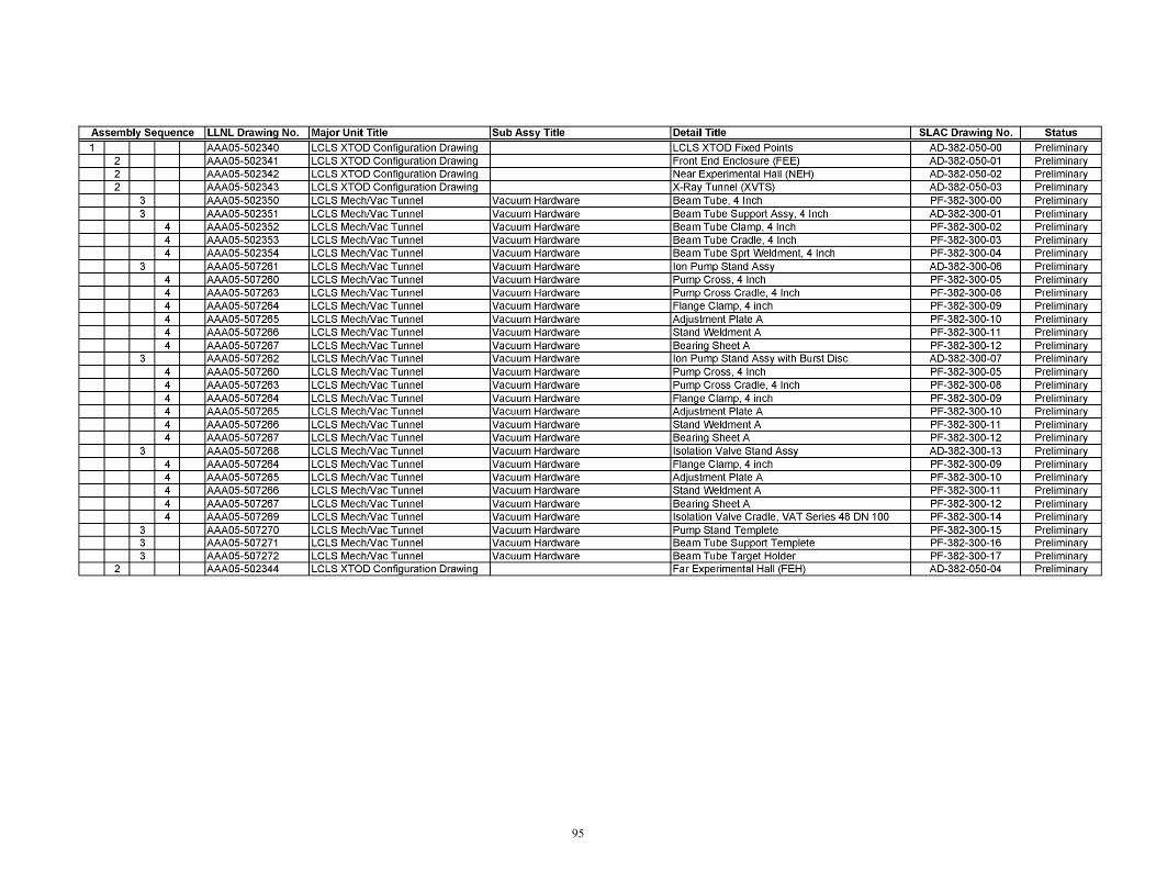
95

96
11.F XVTS Electrical Engineering Control Drawings
The following electrical drawings were prepared at Lawrence Livermore Laboratory for construction and installation of the SLAC LCLS X-Ray Tunnel Vacuum Controls System.
Vacuum Sys. Slow Controls, Rack XT10:1, Profile LEA06-508616, Sheet 1 of 1
Vacuum Sys. Slow Controls, Rack XT10: 1, Installation Plan LEA06-508625, Sheet 1 of 1
Vacuum Sys. Slow Controls, Racks XT20:1, XT20:2, XT30:1, LEA06-508617, Sheet 1 of 1XT30:2 Profiles
Vacuum Sys. Slow Controls, Racks XT20: 1, 20: 2, X-Ray Tunnel Installation Plan LEA06-508626, Sheet 1 of 2
Vacuum Sys. Slow Controls, Racks XT30: 1, 30: 2, X-Ray TunnelInstallation Plan LEA06-508626, Sheet 2 of 2
Vacuum Sys. Slow Controls, Rack XT10: 1, Block Diagram LEA06-508601, Sheet 1 of 1Vacuum Sys. Slow Controls, Rack XT10: 1, Wiring Diagram LEA06-508602, Sheet 1 of 1Vacuum Sys. Slow Controls, Rack XT10: 1, AC Power Diagram LEA06-508611, Sheet 1 of 1Vacuum Sys. Slow Controls, Rack XT10: 1, I/O Power Diagram LEA06-508618, Sheet 1 of 1
Vacuum Sys. Slow Controls, Rack XT20: 1, Block Diagram LEA06-508603, Sheet 1 of 1Vacuum Sys. Slow Controls, Rack XT20: 1, Wiring Diagram LEA06-508604, Sheet 1 of 1Vacuum Sys. Slow Controls, Rack XT20: 1, AC Power Diagram LEA06-508612, Sheet 1 of 1Vacuum Sys. Slow Controls, Rack XT20: 1, 30: 1, I/O Power Diag. LEA06-508611, Sheet 1 of 1
Vacuum Sys. Slow Controls, Rack XT20: 2, Block Diagram LEA06-508605, Sheet 1 of 1Vacuum Sys. Slow Controls, Rack XT20: 2, Wiring Diagram LEA06-508606, Sheet 1 of 1Vacuum Sys. Slow Controls, Rack XT20: 2, AC Power Diagram LEA06-508613, Sheet 1 of 1Vacuum Sys. Slow Controls, Rack XT20: 2, 30: 2, I/O Power Diag. LEA06-508620, Sheet 1 of 1
Vacuum Sys. Slow Controls, Rack XT30: 1, Block Diagram LEA06-508607, Sheet 1 of 1Vacuum Sys. Slow Controls, Rack XT30: 1, Wiring Diagram LEA06-508608, Sheet 1 of 1Vacuum Sys. Slow Controls, Rack XT30: 1, AC Power Diagram LEA06-508614, Sheet 1 of 1
Vacuum Sys. Slow Controls, Rack XT30: 2, Block Diagram LEA06-508609, Sheet 1 of 1Vacuum Sys. Slow Controls, Rack XT30: 2, Wiring Diagram LEA06-508610, Sheet 1 of 1Vacuum Sys. Slow Controls, Rack XT30: 2, AC Power Diagram LEA06-508615, Sheet 1 of 1
LCLS XTOD Single Bay (24U) Rack, Design Data LEA06-508624 Sheet 1 of 1