Embed Size (px)
Citation preview
LIPPERT COMPONENTSCILLLLL
ELECTRIC REAR STABILIZER JACK
OPERATION AND SERVICE MANUAL
2
TABLE OF CONTENTS
SYSTEM……………………………………………........….…..Warning…………………………………........……....Prior to Operation…………………….......………Description………………………………........……..Preventative Maintenance……….......……..
OPERATION………………………………........……………Warning......................................................Extending Stabilizer Jack.............………….Retracting Stabilizer Jack….............……...Manual Operation………………............……..Component Diagram..................................
TROUBLESHOOTING.……..………………........………Stabilizer Jack..........................................Motor.........................................................Chart.........................................................Wiring Diagram…………………….........…….
33445
556668
1010101112
SYSTEM
WARNINGFAILURE TO ACT IN ACCORDANCE WITH THE FOLLOWING MAY
RESULT IN SERIOUS PERSONAL INJURY OR DEATH.
THE LIPPERT ELECTRIC REAR STABILIZER JACK IS INTENDED FOR THEPURPOSE OF STABILIZING THE REAR END OF THE UNIT. THE USE OFTHIS SYSTEM FOR ANY REASON OTHER THAN WHICH IT IS INTENDED ISPROHIBITED BY LIPPERT’S LIMITED WARRANTY AND MAY RESULT INSERIOUS PERSONAL INJURY OR DEATH.
THE LIPPERT ELECTRIC REAR STABILIZER JACK IS DESIGNED AS ASTABILIZING COMPONENT SYSTEM AND SHOULD NOT BE USED TOPROVIDE SERVICE FOR ANY REASON UNDER THE COACH SUCH ASCHANGING TIRES OR SERVICING ANYTHING BENEATH THE UNIT.
LIPPERT COMPONENTS, INC. RECOMMENDS THAT A TRAINEDPROFESSIONAL BE EMPLOYED TO CHANGE THE TIRE ON THE COACH.ANY ATTEMPTS TO CHANGE TIRES OR PERFORM OTHER SERVICE WHILECOACH IS SUPPORTED BY THE LIPPERT ELECTRIC REAR STABILIZERJACK COULD RESULT IN DAMAGE TO THE COACH AND/OR CAUSESERIOUS PERSONAL INJURY OR DEATH.
WARNING! – BE SURE TO PARK THE UNIT ON SOLID, LEVEL GROUND.
WARNING! – CLEAR ALL STABILIZER JACK LANDING LOCATIONS OF DEBRIS AND OBSTRUCTIONS. LOCATIONS SHOULD ALSO BE FREE OF DEPRESSIONS.
WARNING! – WHEN PARKING THE UNIT ON EXTREMELY SOFT SURFACES, UTILIZE LOAD DISTRIBUTION PADS UNDER EACH JACK.
WARNING! - PEOPLE AND PETS SHOULD BE CLEAR OF COACH WHILE OPERATING LEVELING SYSTEM.
WARNING! - NEVER LIFT THE COACH COMPLETELY OFF THE GROUND. LIFTING THE COACH SO THE WHEELS ARE NOT TOUCHING GROUND WILL CREATE AN UNSTABLE AND UNSAFE CONDITION.
3
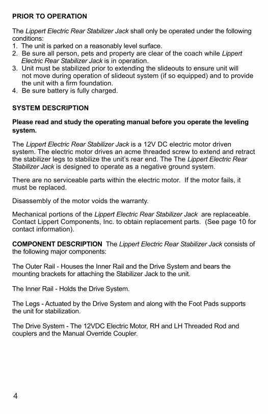
PRIOR TO OPERATION
The Lippert Electric Rear Stabilizer Jack shall only be operated under the followingconditions:1. The unit is parked on a reasonably level surface.2. Be sure all person, pets and property are clear of the coach while Lippert Electric Rear Stabilizer Jack is in operation.3. Unit must be stabilized prior to extending the slideouts to ensure unit will not move during operation of slideout system (if so equipped) and to provide the unit with a firm foundation.4. Be sure battery is fully charged.
SYSTEM DESCRIPTION
Please read and study the operating manual before you operate the levelingsystem.
The Lippert Electric Rear Stabilizer Jack is a 12V DC electric motor drivensystem. The electric motor drives an acme threaded screw to extend and retractthe stabilizer legs to stabilize the unit’s rear end. The The Lippert Electric RearStabilizer Jack is designed to operate as a negative ground system.
There are no serviceable parts within the electric motor. If the motor fails, itmust be replaced.
Disassembly of the motor voids the warranty.
Mechanical portions of the Lippert Electric Rear Stabilizer Jack are replaceable.Contact Lippert Components, Inc. to obtain replacement parts. (See page 10 forcontact information).
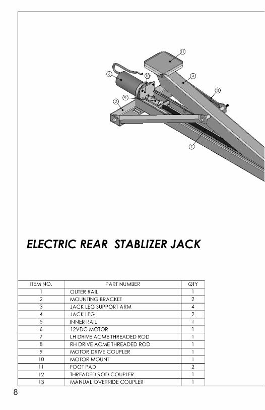
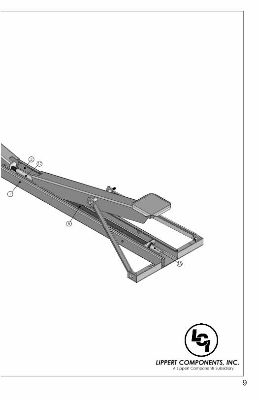
COMPONENT DESCRIPTION The Lippert Electric Rear Stabilizer Jack consists ofthe following major components:
The Outer Rail - Houses the Inner Rail and the Drive System and bears themounting brackets for attaching the Stabilizer Jack to the unit.
The Inner Rail - Holds the Drive System.
The Legs - Actuated by the Drive System and along with the Foot Pads supportsthe unit for stabilization.
The Drive System - The 12VDC Electric Motor, RH and LH Threaded Rod andcouplers and the Manual Override Coupler.
4
WARNING!YOUR COACH SHOULD BE SUPPORTED AT BOTH FRONT AND REAR
AXLES WITH JACK STANDS BEFORE WORKING UNDERNEATH.FAILURE TO DO SO MAY RESULT IN PERSONAL INJURY OR DEATH.
SYSTEM MAINTENANCE
It is recommended that when operating in harsh environments (road salt, icebuild up, etc.) the moving parts be kept clean and can be washed with mild soapand water. No grease or lubrication is necessary and in some situations may bedetrimental to the environment and long term dependability of the system.
WARNING!DO NOT WORK ON YOUR STABILIZER JACK UNLESS THE BATTERY IS
DISCONNECTED. FAILURE TO ACT IN ACCORDANCE WITH THEFOLLOWING MAY RESULT IN SERIOUS PERSONAL INJURY OR DEATH.
ELECTRICAL SYSTEM MAINTENANCE
For optimum performance, the system requires full battery current and voltage.The battery must be maintained at full capacity. Other than good batterymaintenance, check the terminals and other connections at the battery, thecontrol switch, and the electric motor for corrosion, and loose or damagedterminals. Check motor leads under the trailer chassis. Since these connectionsare subject to damage from road debris, be sure they are in good condition.
Note: The Lippert Electric Rear Stabilizer Jack is designed to operate as anegative ground system. A negative ground system utilizes the chassis frameas a ground and an independent ground wire back to battery is necessary (seepage 9 for wiring diagram). It is important that the electrical components havegood wire to chassis contact. Over 90% of unit electrical problems are due tobad ground connections.
OPERATIONWARNING!
FAILURE TO ACT IN ACCORDANCE WITH THE FOLLOWING MAY RESULTIN SERIOUS PERSONAL INJURY OR DEATH.
ALWAYS MAKE SURE THAT THE LIPPERT ELECTRIC REAR STABILIZERJACK PATH IS CLEAR OF PEOPLE AND OBJECTS BEFORE AND DURINGOPERATION OF THE STABILIZER JACK..
ALWAYS KEEP AWAY FROM THE STABILIZER JACK WHEN THE IT IS BEINGOPERATED. THERE ARE AREAS THAT MAY PINCH OR CATCH ON LOOSECLOTHING CAUSING PERSONAL INJURY.
5
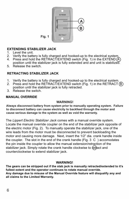
EXTENDING STABILIZER JACK1. Level the unit.2. Verify the battery is fully charged and hooked-up to the electrical system.4. Press and hold the RETRACT/EXTEND switch (Fig. 1) in the EXTEND A
position until the stabilizer jack is fully extended and and unit is stabilized.5. Release the switch.
RETRACTING STABILIZER JACK
1. Verify the battery is fully charged and hooked-up to the electrical system.2. Press and hold the RETRACT/EXTEND switch (Fig. 1) in the RETRACT B
position until the stabilizer jack is fully retracted.3. Release the switch.
Fig. 1
A
B
MANUAL OVERRIDE
The Lippert Electric Stabilizer Jack comes with a manual override system.Locate the manual override coupler on the end of the stabilizer jack opposite ofthe electric motor (Fig. 2). To manually operate the stabilizer jack, one of thewire leads from the motor must be disconnected to prevent backloading themotor and causing more damage. Next, insert the 1/2” dia. crank handle insidethe coupler. The slot in the end of the crank handle (Fig. 3 C ) accomodatesthe pin inside the coupler to allow the manual extension/retraction of thestabilizer jack. Simply rotate the crank handle clockwise to retract andcounterclockwise to extend stabilizer jack.
6
WARNING!The gears can be stripped out if the stab jack is manually retracted/extended to it’sfullest extent and the operator continues to rotate manual override.Any damage due to misuse of the Manual Override feature will disqualify any andall claims to the Limited Warranty.
WARNING!Always disconnect battery from system prior to manually operating system. Failureto disconnect battery can cause electricity to backfeed through the motor andcause serious damage to the system as well as void the warranty.
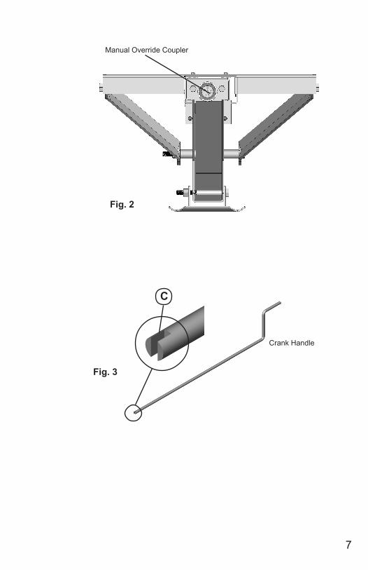
Fig. 2
Fig. 3
Manual Override Coupler
Crank Handle
C
7
8
9
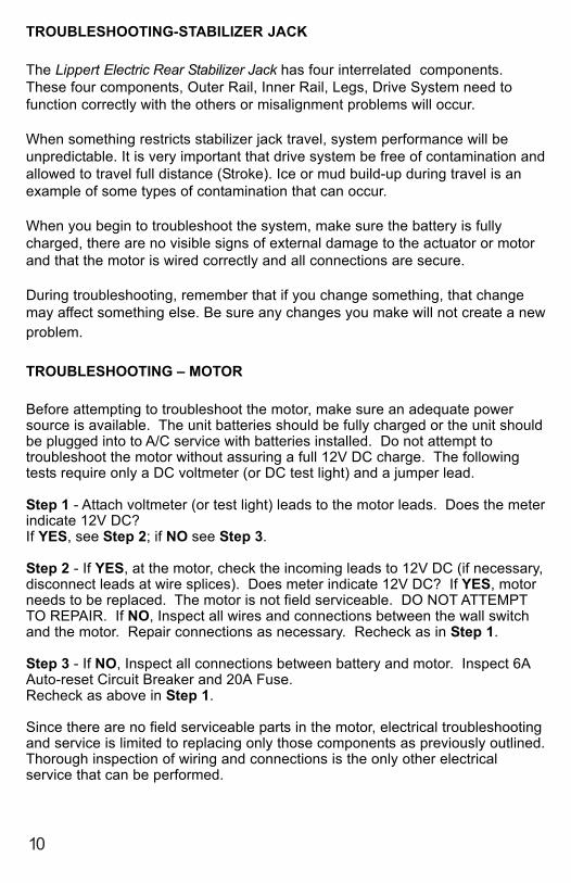
TROUBLESHOOTING-STABILIZER JACK
The Lippert Electric Rear Stabilizer Jack has four interrelated components.These four components, Outer Rail, Inner Rail, Legs, Drive System need tofunction correctly with the others or misalignment problems will occur.
When something restricts stabilizer jack travel, system performance will beunpredictable. It is very important that drive system be free of contamination andallowed to travel full distance (Stroke). Ice or mud build-up during travel is anexample of some types of contamination that can occur.
When you begin to troubleshoot the system, make sure the battery is fullycharged, there are no visible signs of external damage to the actuator or motorand that the motor is wired correctly and all connections are secure.
During troubleshooting, remember that if you change something, that changemay affect something else. Be sure any changes you make will not create a newproblem.
TROUBLESHOOTING – MOTOR
Before attempting to troubleshoot the motor, make sure an adequate powersource is available. The unit batteries should be fully charged or the unit shouldbe plugged into to A/C service with batteries installed. Do not attempt totroubleshoot the motor without assuring a full 12V DC charge. The followingtests require only a DC voltmeter (or DC test light) and a jumper lead.
Step 1 - Attach voltmeter (or test light) leads to the motor leads. Does the meterindicate 12V DC?If YES, see Step 2; if NO see Step 3.
Step 2 - If YES, at the motor, check the incoming leads to 12V DC (if necessary,disconnect leads at wire splices). Does meter indicate 12V DC? If YES, motorneeds to be replaced. The motor is not field serviceable. DO NOT ATTEMPTTO REPAIR. If NO, Inspect all wires and connections between the wall switchand the motor. Repair connections as necessary. Recheck as in Step 1.
Step 3 - If NO, Inspect all connections between battery and motor. Inspect 6AAuto-reset Circuit Breaker and 20A Fuse.Recheck as above in Step 1.
Since there are no field serviceable parts in the motor, electrical troubleshootingand service is limited to replacing only those components as previously outlined.Thorough inspection of wiring and connections is the only other electricalservice that can be performed.
10
11
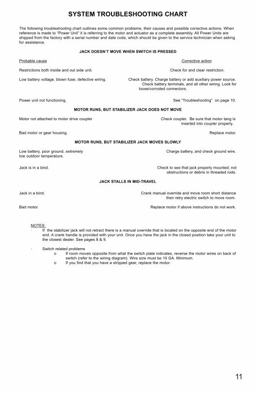
SYSTEM TROUBLESHOOTING CHART
The following troubleshooting chart outlines some common problems, their causes and possible corrective actions. Whenreference is made to “Power Unit” it is referring to the motor and actuator as a complete assembly. All Power Units areshipped from the factory with a serial number and date code, which should be given to the service technician when askingfor assistance.
JACK DOESN’T MOVE WHEN SWITCH IS PRESSED
Probable cause Corrective action
Restrictions both inside and out side unit. Check for and clear restriction.
Low battery voltage, blown fuse, defective wiring. Check battery. Charge battery or add auxiliary power source. Check battery terminals, and all other wiring. Look for
loose/corroded connectors.
Power unit not functioning. See “Troubleshooting” on page 10.
MOTOR RUNS, BUT STABILIZER JACK DOES NOT MOVE
Motor not attached to motor drive coupler Check coupler. Be sure that motor tang is inserted into coupler properly.
Bad motor or gear housing. Replace motor.
MOTOR RUNS, BUT STABILIZER JACK MOVES SLOWLY
Low battery, poor ground, extremely Charge battery, and check ground wire.low outdoor temperature.
Jack is in a bind. Check to see that jack properly mounted; not obstructions or debris in threaded rods.
JACK STALLS IN MID-TRAVEL
Jack in a bind. Crank manual override and move room short distance then retry electric switch to move room.
Bad motor. Replace motor if above instructions do not work.
NOTES:· If the stabilizer jack will not retract there is a manual override that is located on the opposite end of the motor
end. A crank handle is provided with your unit. Once you have the jack in the closed position take your unit tothe closest dealer. See pages 8 & 9.
· Switch related problemso If room moves opposite from what the switch plate indicates, reverse the motor wires on back of
switch (refer to the wiring diagram). Wire size must be 10 GA. Minimum.o If you find that you have a stripped gear, replace the motor.
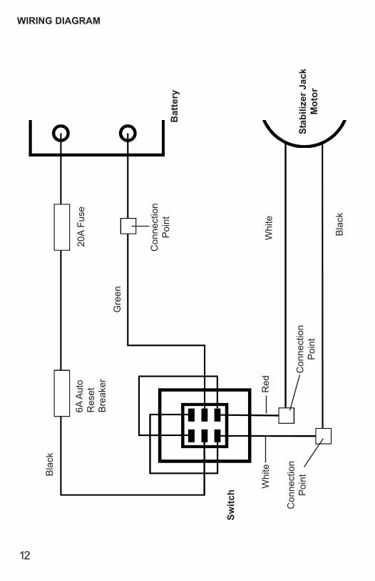
WIRING DIAGRAM
20A
Fus
e6A
Aut
oR
eset
Bre
aker
Con
nect
ion
Poi
nt
Con
nect
ion
Poi
nt
Con
nect
ion
Poi
ntBla
ck
Gre
en
Red
Whi
teW
hite
Bla
ck
Stab
ilize
r Jac
kM
otor
Bat
tery
Switc
h
12