Embed Size (px)
Citation preview
LCF AND TMF CRACK GROWTH IN CAST NICKEL-BASED SUPERALLOYSREPORT 2018:492

LCF and TMF Crack Growth in Cast Nickel-based Superalloys
KME-702
DANIEL LEIDERMARK JOHAN MOVERARE KJELL SIMONSSON
DAVID GUSTAFSSON CHRISTIAN BUSSE FRANS PALMERT
ISBN 978-91-7673-492-6 | © Energiforsk April 2018
Energiforsk AB | Phone: 08-677 25 30 | E-mail: [email protected] | www.energiforsk.se

LCF AND TMF CRACK GROWTH IN CAST NICKEL-BASED SUPERALLOYS
3
Foreword
The project has been performed within the framework of the materials technology research programme KME, Consortium materials technology for thermal energy processes, period 2014-2018. The consortium is at the forefront of developing material technology to create maximum efficiency for energy conversion of renewable fuels and waste. KME has its sights firmly set on continuing to raise the efficiency of long-term sustainable energy as well as ensuring international industrial competitiveness.
KME was established 1997 and is a multi-cliental group of companies over the entire value chain, including stakeholders from the material producers, manufacturers of systems and components for energy conversion and energy industry (utilities), that are interested in materials technology research. In the current programme stage, eight industrial companies and 14 energy companies participate in the consortium. The consortium is managed by Energiforsk.
The programme shall contribute to increasing knowledge within materials technology and process technology development to forward the development of thermal energy processes for efficient utilisation of renewable fuels and waste in power and heat production. The KME goals are to bring about cost-effective materials solutions for increased availability and power production, improved fuel flexibility and improved operating flexibility, with low environmental impact.
KME’s activities are characterised by long term industry and demand driven research and constitutes an important part of the effort to promote the development of new energy technology with the aim to create value and an economic, environmentally friendly and long term sustainable energy society.
Johan Moverare, LiU, has been the project leader. Daniel Leidermark, Christian Busse, Frans Palmert, Kjell Simonsson, David Gustafsson and Björn Sjödin have been project members. The reference group for the project consisted of Rikard Norling, Swerea KIMAB and Magnus Colliander (Hörnqvist), Chalmers. Siemens Industrial Turbomachinery AB has participated in the project through own investment (60 %) and the Swedish Energy Agency has financed the academic partners (40 %).
The report is a short version of the complete KME report.
Energiforsk would like to thank all the participants for a well performed project.
Bertil Wahlund, Energiforsk
These are the results and conclusions of a project, which is part of a research program run by Energiforsk. The author/authors are responsible for the content.
LCF AND TMF CRACK GROWTH IN CAST NICKEL-BASED SUPERALLOYS
4
Sammanfattning
I dagens samhälle, finns en allt större efterfrågan på gasturbiner för ökad cyklisk drift, vilka behövs som komplement till intermittenta förnyelsebara energikällor såsom sol- och vindkraft. Eftersom stationära gasturbiner för energiproduktion traditionellt har designats för kontinuerlig baslast ger en sådan ändring i driftsvillkor, i termer av ökande antal start-stopp-cykler, en ökad risk för maskinell skada och driftstörning. Detta, tillsammans med krav på bränsleflexibilitet, gör att nya, mer korrosionsbeständiga, material och skyddsbeläggningar behöver introduceras i maskinerna.
I detta projekt har termomekanisk utmattningssprickväxt undersökts för två olika typer av gjutna nickelbaserade turbinbladsmaterial. Den ena av dem utgörs av en välbeprövad legering, medan det andra är ett nyutvecklat enkristallint turbinmaterial, speciellt framtaget för att möta ovan beskrivna krav, där dock avsaknaden av korngränser gör att sprickväxtbeteendet skiljer sig markant från konventionella material. Detta blir bland annat uppenbart då sprickan under vissa temperatur- och lastförhållanden kan byta till kristallografisk sprickväxt; ett beteende som utifrån ett tillämpningsperspektiv är oerhört centralt att kunna förstås och predikteras, och som därför legat i fokus i projektet.
Mekanisk provning och materialstudier har genomförts i projektet och använts för att ta fram förbättrade beräkningsmetoder och materialspecifika parametrar för sprickväxtprediktering i gasturbinblad. För verifiering av de framtagna nya prov- och beräkningsmetoderna, så har det ovan nämnda konventionella gastturbinmaterialet använts.
Projektresultat har avrapporterats i form av en större mängd vetenskapliga tidskriftspublikationer och konferensbidrag, och täcker alla inom projektet specificerade delområden. Resultat från projektet har också redan implementerats av SIEMENS Industrial Turbomachinery AB i dess designprocess för nya turbiner med fokus på bränsleflexibilitet och cyklisk drift.
LCF AND TMF CRACK GROWTH IN CAST NICKEL-BASED SUPERALLOYS
5
Summary
Today, there is a growing demand for gas turbines for cyclical operation. These turbines are needed as a complement to the intermittent energy sources such as solar and wind power, which cannot be regulated in the same way as a gas turbine. Since gas turbines have traditionally been designed for base loads, a change in operating conditions, such as more start stop-cycles, will lead to an increased risk for damage and failure. In addition, the requirements for fuel flexibility also increases, which means that new and more corrosion-resistant materials and coatings must be introduced.
In this project, we have investigated crack growth during thermomechanical fatigue in two different types of cast nickel-based alloys for turbine blades. One of them is a newly developed alloy specially designed for industrial gas turbines to meet the challenges described above. As the alloy is a so-called single-crystal, completely without grain boundaries, crack growth differs significantly from conventional materials. Among other things, these materials show two distinctly different modes of crack propagation behaviour as the crack under certain load and temperature conditions changes to a crystallographic failure mode. In the project, this behaviour has been mapped for a variety of temperature and load conditions.
The results from material studies and mechanical testing have been used to develop a new calculation methodology and new fracture mechanics parameters for crack growth in material for gas turbine blades. To verify the new test and calculation methods developed within the project, a more traditional conventionally cast nickel-base alloy has also been studied.
Results from the project are already implemented by Siemens Industrial Turbomachinery AB, in their development of new turbines focusing on fuel flexibility and cyclical operation.
LCF AND TMF CRACK GROWTH IN CAST NICKEL-BASED SUPERALLOYS
6
List of content
1 Introduction 7 1.1 Background 7 1.2 Goal 8
2 Methods 10 2.1 Materials 10 2.2 Test specimens 10 2.3 Isothermal Mechanical testing 12
2.3.1 Isothermal testing using the DCT-specimen 12 2.3.2 Isothermal testing using the Kb-specimen 12
2.4 Thermomechanical fatigue crack growth testing 12 2.5 micrustructural investigations 14 2.6 Modelling 16
2.6.1 Finite element context 16 2.6.2 Crack growth anisotropy 16 2.6.3 Crystallographic crack driving force 17 2.6.4 Handling inelasticity 19
2.7 Component-near demonstrator 19 3 Results and discussion 20
3.1 ISO thermal results and analyses – DCT specimen 20 3.1.1 DCT results at 20°C 20 3.1.2 DCT results at 500°C 22 3.1.3 DCT results at 750°C 25
3.2 TMF Crack growth results and analyses 27 3.2.1 IN792: IP-TMF compared to isothermal results 27 3.2.2 IN792: OP-TMF 29 3.2.3 IN792 crack propagation mechanisms 29 3.2.4 New SX: IP-TMF compared to isothermal results 29 3.2.5 New SX: OP-TMF 30 3.2.6 Influence of long term ageing on TMF properties of the newly
developed single-crystal material 31 3.3 Modelling results 31
3.3.1 Numerical study of the influence of crystallographic orientation and misalignments 31
3.3.2 Crystallographic crack driving force 34 4 Conclusions 38 5 Literature references 40 6 Publications 41
LCF AND TMF CRACK GROWTH IN CAST NICKEL-BASED SUPERALLOYS
7
1 Introduction
1.1 BACKGROUND
Due to the intermittent nature of renewable energy sources like solar and wind power, there is a need for flexible backup power for balancing the grid, a task well suited for gas turbine and combined cycle power plants. However, these increased demands on cyclic capacity and reduced start up times, in combination with increased demands on higher temperatures and fuel flexibility, calls for improved material knowledge and life prediction methodologies to ensure structural integrity of key components of these machines. It is here to be noted that structural components in gas turbines, as well as in steam turbines, are subjected to rather complex stress and temperature cycles due to the temperature gradients that occur during engine start-up and shut-down or within components during steady-state operation. The accumulated effect of such stress and temperature cycles leads to the possibility of failure by thermomechanical fatigue (TMF), which must be avoided by appropriate design of the components and choice of operating conditions. However, the service life of many hot components is not fully restricted by the number of cycles to crack initiation since, especially close to stress concentrations; one has also to rely on stable and predictable crack propagation, which means that a certain amount of crack propagation is allowed before the component has to be replaced in service. Such damage tolerant approaches demand accurate predictions of the fatigue crack propagation (FCP) under the influence of simultaneous cycling of temperature and mechanical loads. Although methods have been developed to predict FCP rates under isothermal conditions over a wide range of temperatures, frequencies and load ratios, as well as under sustained load/dwell times, only very few published studies on crack propagation under TMF conditions are available. Furthermore, since the translation of isothermally obtained fatigue crack propagation data into a true TMF context is questionable, the need for more experimental studies in this field is obvious. Unfortunately, mechanical testing under dynamic temperature conditions is more complex than other more traditional isothermal testing techniques.
Crack propagation in single-crystal materials add an extra dimension of complexity since the failure modes are complicated due to the material anisotropy, the effect of crystal orientation and the very high temperatures that are typically of interest for single-crystal components. In addition, previous studies within KME-403, KME-410 and KME- 502 have shown that the deformation in single-crystal materials is often very localized to a number of crystallographic deformation bands and that cracks follow these bands very easily. Thus, the cracks cannot be expected to follow the KI-dependency (i.e. crack growth perpendicular to the applied load) commonly observed in conventional materials.
Based on the above described indutrial needs, previous work and current state of knowledge (cf. next section), the here reported project KME 702 has focused on the following two goals of the KME-programme:
LCF AND TMF CRACK GROWTH IN CAST NICKEL-BASED SUPERALLOYS
8
“To test and validate new materials and surface coatings for future industrial gas turbines in order to permit high fuel flexibility, availability and efficiency, as well as cyclic operation.”
“To evaluate the mechanical properties and service life of various materials in relation to new material requirements for more efficient electricity production”
Furthermore, two different materials have been investigated in the project; (1) Conventionally cast IN792 which is commonly used in turbine blades for industrial gas turbines, (2) a newly developed single-crystal material.
1.2 GOAL
The overall goal of the here reported research project KME 702 has been to address and solve material related research questions central for the next generation of advanced gas turbines, and in this way contribute to the development towards a sustainable and efficient global energy system.
The specific goal of the project has been to validate materials and lifing methods for future industrial gas turbines where there is a strong need for high fuel flexibility, availability and efficiency, as well as cyclic operation, with main focus on TMF loading situations and single-crystal materials.
The following project goals have been defined and carried out. Each task is further elaborated in what we mean with them.
1. Validation of a TMF crack growth test method that can be used to generate high quality data for cast nickel-based superalloys, including single-crystals.
As there is no standard for how to do TMF-crack growth testing we must be confident that our method can generate reliable and satisfactory results. This can be done by scrutinizing the results from many different aspects, i.e. repeatability, amount of scatter, consistency between different test conditions and comparison with isothermal data.
2. Generation of high quality test data for TMF crack growth in conventionally cast IN792 and the newly developed single-crystal material.
The amount of data generated in the project should be enough in order to generate at material model that can describe the general material behaviour under relevant temperarures and load conditions.
3. Improvement of the knowledge regarding the mechanisms that controls the crack growth rate for conventionally cast superalloys as well as for single-crystal superalloys (e.g. influence of crystal orientation, phase shift and temperature- strain history).
As the reseacrh project progresses, knowledge with respect to the above mentioned goal and underlying phenomna will be gained.
4. Development of TMF crack growth models and life prediction methodologies that will reduce the need high safety margins. Today the
LCF AND TMF CRACK GROWTH IN CAST NICKEL-BASED SUPERALLOYS
9
safety of single-crystal crack growth is in the order of three decades. The idea is to bring this order of magnitude down by one decade.
To predict the life of a single-crystal component, a crack growth model is needed to evaluate the observed cracking behaviour. A working methodology will, in turn, contribute in reducing the conservative safety margin of today, through increased knowlegde about the driving force.
5. Validation of the models for component near conditions.
More specifically, a validation of the crack growth methodology on a component like geometry with an engine relevant load cycle is to be performed.
LCF AND TMF CRACK GROWTH IN CAST NICKEL-BASED SUPERALLOYS
10
2 Methods
2.1 MATERIALS
One of the tested material is an alternative single-crystal nickel-base superalloy developed by Siemens Industrial Turbomachinery AB, similar to the alloy described in a publication by Reed et al [1]. Its main alloying elements, in order of decreasing wt%, are as follows: Ni-Cr-Ta-Co-Al-W-Mo-Si-Hf-C-Ce. The microstructure mainly consists of a γ-matrix precipitation strengthened by approximately 50 vol% of γ′ -particles. The majority of the γ′ is in the form of primary cuboidal particles, but smaller secondary γ′ particles are also present within the γ-channels, and the microstructure also contains carbides and casting pores. The other material of interest has been IN792, a conventional cast γ´-precipitation hardened nickel-based superalloy. The chemical composition is Ni–12.4Cr–8.9Co–1.8Mo–4.0W–3.5Al–4.0Ti–4.1Ta–0.08C–0.017B–0.019Zr (wt.%). After conventional casting the material was hot isostatically pressed (HIP) at 1195 ◦C and 150MPa for 2 h followed by solution heat treatment at 1121 ◦C for 2 h and ageing at 850 ◦C for 24 h. Typically the grain size is rather large and a lot of carbides are formed at the interdendritic areas, carbides together with borides can also be observed in the grain boundaries. The primary γ´-phase typically has a size about 0.6–0.7µm and can have both an irregular and a cubic appearance. In addition, much smaller secondary γ´-particles are also present along with larger γ/γ´ eutectic domains.
2.2 TEST SPECIMENS
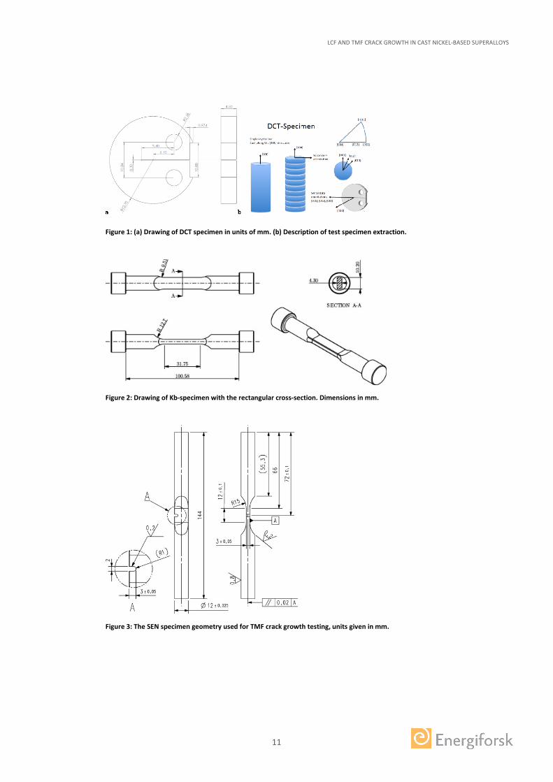
Three different test specimen geometries for crack propagation testing has been used. Isothermal crack growth testing was performed on the single-crystal material using disk shaped compact tension (DCT) specimens. The specimens were extracted, in three different crystallographic orientations, from a round bar with a diameter of 25mm, see Figure 1. Isothermal fatigue crack growth tests were performed on both materials using a Kb-type (surface crack) specimen with rectangular cross sections of 4.3 × 10.2 mm, see Figure 2. Thermo-mechanical fatigue crack growth testing was performed on both materials using a single-edge notched (SEN) specimen geometry, seen in Figure 3. Crack growth at elevated temperature was monitored by direct current potential drop (DCPD) in the case of DCT and Kb. For the TMF tests (the SEN specimen geometry) the crack growth was monitored using the compliance method as outlined in ASTM E647 and further modified by [2].
LCF AND TMF CRACK GROWTH IN CAST NICKEL-BASED SUPERALLOYS
11
Figure 1: (a) Drawing of DCT specimen in units of mm. (b) Description of test specimen extraction.
Figure 2: Drawing of Kb-specimen with the rectangular cross-section. Dimensions in mm.
Figure 3: The SEN specimen geometry used for TMF crack growth testing, units given in mm.
LCF AND TMF CRACK GROWTH IN CAST NICKEL-BASED SUPERALLOYS
12
2.3 ISOTHERMAL MECHANICAL TESTING
2.3.1 Isothermal testing using the DCT-specimen
Fatigue crack growth testing of the newly developed single-crystal material was performed at 20°C, 500°C and 750°C according to ASTM E647. The specimens had an Electro Discharge Machined (EDM) starter notch and were fatigue pre-cracked at room temperature with a frequency of 10 Hz. During the pre-cracking and room temperature testing, the crack opening displacement was measured using a clip gauge extensometer and the crack length was determined by the compliance method. The tests at 500°C were run with a hold time of 30s at maximum force in each cycle. At 750°C tests were run with 30s, 1h and 24h hold time at maximum force. The hold times were varied in blocks within the same test. The crack length was monitored using pulsed direct current potential drop measurement (DCPD).
In some tests performed in the present work, crystallographic crack growth along {111} planes were observed. In these tests, the crystallographic crack growth was limited to certain parts of the crack front. The central part of the crack front remained non-crystallographic and perpendicular to the loading direction throughout all tests.
2.3.2 Isothermal testing using the Kb-specimen
Fatigue crack growth testing of surface flawed Kb specimens in material IN792 and the newly developed single-crystal material was done according to the guidelines provided in the ASTM E647-15 test specification. The fatigue crack growth testing was done at temperatures of 500ºC, 750ºC and 850ºC using a triangular waveform with 1s ramp up time and 1s ramp down time. Testing with hold times of 1h and 6h at maximum load was done at 750ºC and 850ºC. At these temperatures some static load crack growth tests were also performed. Prior to testing, a semi-circular surface flaw was introduced by electro discharge machining (EDM). The test specimens were then fatigue pre-cracked to the desired initial crack length. The crack length was monitored using direct current potential drop measurement (DCPD). The specimens were heat tinted at least 3 times during the test, in order to mark the crack front and enable calibration of the potential drop measurement.
2.4 THERMOMECHANICAL FATIGUE CRACK GROWTH TESTING
TMF crack growth testing on IN792 and the newly developed single-crystal material was performed using the notched SEN-type specimen seen in Figure 3. For most test on the newly developed single-crystal material the nominal crystal orientation was <001> in the axial direction and <010> in the crack depth direction.
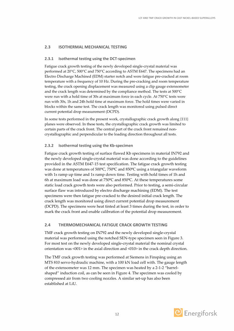
The TMF crack growth testing was performed at Siemens in Finspång using an MTS 810 servo-hydraulic machine, with a 100 kN load cell with. The gauge length of the extensometer was 12 mm. The specimen was heated by a 2-1-2 “barrel-shaped” induction coil, as can be seen in Figure 4. The specimen was cooled by compressed air from two cooling nozzles. A similar set-up has also been established at LiU.
LCF AND TMF CRACK GROWTH IN CAST NICKEL-BASED SUPERALLOYS
13
Figure 4 - Test set-up for TMF crack growth testing at Siemens, Finspång.
A camera was used to monitor the crack and record images from one side (front) of the specimen. An image is recorded automatically at pre-defined cycle intervals. Prior to testing, reference scribes have been placed on the surface of the specimen in order to facilitate the crack length evaluation. The optical crack length measurements were generally not used in the evaluation of crack growth rate but rather used to facilitate the control of the tests and to verify the results from the compliance method. The crack length in each cycle was determined using the compliance method, adapted for TMF conditions. A detailed description of the method has been published by Ewest et al. [2].
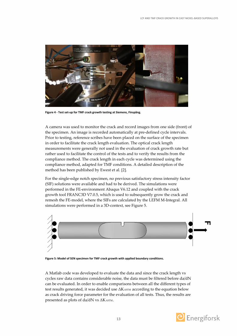
For the single-edge notch specimen, no previous satisfactory stress intensity factor (SIF) solutions were available and had to be derived. The simulations were performed in the FE-environment Abaqus V6.12 and coupled with the crack growth tool FRANC3D V7.0.5, which is used to subsequently grow the crack and remesh the FE-model, where the SIFs are calculated by the LEFM M-Integral. All simulations were performed in a 3D-context, see Figure 5.
Figure 5: Model of SEN specimen for TMF crack growth with applied boundary conditions.
A Matlab code was developed to evaluate the data and since the crack length vs cycles raw data contains considerable noise, the data must be filtered before da/dN can be evaluated. In order to enable comparisons between all the different types of test results generated, it was decided use ΔKASTM according to the equation below as crack driving force parameter for the evaluation of all tests. Thus, the results are presented as plots of da/dN vs ΔKASTM.
LCF AND TMF CRACK GROWTH IN CAST NICKEL-BASED SUPERALLOYS
14
[ ]2minmin
minmax
)Re()(
)(
KK
KKK ASTM
=
−=∆
+
+
The crack length used to evaluate Kmax and Kmin is the average crack length along the crack front, as measured by the compliance method. It is possible to evaluate ΔKASTM even for crystallographic cracks which are non-perpendicular to the loading direction. However, the physical basis for such evaluation is questionable and therefore the data for crystallographic cracks has been plotted as dashed lines. ΔKASTM was evaluated based on the K-solution for mode I cracks, using the apparent average crack length as measured either by the compliance method or by the potential drop method calibrated for mode I cracks. Finding a suitable description of the driving force for crystallographic crack growth is a complex task, which will not be further discussed here (treated within an ongoing PhD project).
ΔKASTM may be regarded as the effective ΔK under the assumption that the crack opening force is either zero or equal to the minimum force of the cycle, whichever is greater. For the isothermal tests performed, it is not possible to evaluate the actual crack opening force since the strain was not measured in these tests. For the TMF crack growth tests it may be possible to evaluate the actual crack opening force, but a suitable evaluation method is yet to be developed.
2.5 MICRUSTRUCTURAL INVESTIGATIONS
After testing, specimens were examined in stereo microscope and scanning electron microscope (SEM). Both fracture surfaces and polished cross-sections were examined in the SEM (Hitachi SU70 FEG-SEM for cross-sections and JEOL JSM-6610LV for fracture surfaces). In all micrographs of polished cross-sections, the loading axis is aligned in the vertical direction. For the purpose of determining the crystallographic orientation of the DCT and Kb specimens, the specimens were polished and etched with Kalling’s #1 (5g CuCl2, 100ml HCl, 100ml ethanol) in order to reveal the dendrite structure.
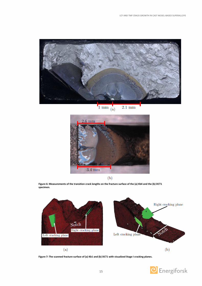
For the Kb specimens, the shape of the growing crack can be seen due to heat tinting during the testing, cf. Figure 6a, and can be approximated to be semi-circular. No heat tinting was done in the testing of the DCT specimens and therefore semi-elliptical crack front shapes with a shallow depth have been assumed. The fracture surfaces of the specimens were also scanned in an Atos Triple Scan machine to acquire a 3D representation of the fracture surfaces in terms of mesh data. These were imported to an FE-preprocessor, where planes with the corresponding normals to the {111}-planes were added for visualisation. This is a convenient procedure to identify the crystallographic plane on which the Stage I crack grew as seen in Figure 7.
LCF AND TMF CRACK GROWTH IN CAST NICKEL-BASED SUPERALLOYS
15
Figure 6: Measurements of the transition crack lengths on the fracture surface of the (a) Kb4 and the (b) DCT1 specimen.
Figure 7: The scanned fracture surface of (a) Kb1 and (b) DCT1 with visualized Stage I cracking planes.
LCF AND TMF CRACK GROWTH IN CAST NICKEL-BASED SUPERALLOYS
16
2.6 MODELLING
2.6.1 Finite element context
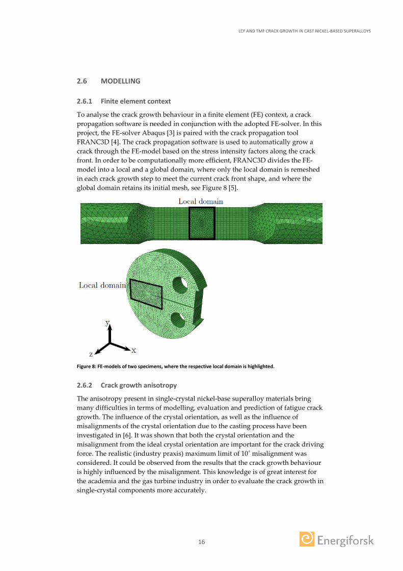
To analyse the crack growth behaviour in a finite element (FE) context, a crack propagation software is needed in conjunction with the adopted FE-solver. In this project, the FE-solver Abaqus [3] is paired with the crack propagation tool FRANC3D [4]. The crack propagation software is used to automatically grow a crack through the FE-model based on the stress intensity factors along the crack front. In order to be computationally more efficient, FRANC3D divides the FE-model into a local and a global domain, where only the local domain is remeshed in each crack growth step to meet the current crack front shape, and where the global domain retains its initial mesh, see Figure 8 [5].
Figure 8: FE-models of two specimens, where the respective local domain is highlighted.
2.6.2 Crack growth anisotropy
The anisotropy present in single-crystal nickel-base superalloy materials bring many difficulties in terms of modelling, evaluation and prediction of fatigue crack growth. The influence of the crystal orientation, as well as the influence of misalignments of the crystal orientation due to the casting process have been investigated in [6]. It was shown that both the crystal orientation and the misalignment from the ideal crystal orientation are important for the crack driving force. The realistic (industry praxis) maximum limit of 10˚ misalignment was considered. It could be observed from the results that the crack growth behaviour is highly influenced by the misalignment. This knowledge is of great interest for the academia and the gas turbine industry in order to evaluate the crack growth in single-crystal components more accurately.
LCF AND TMF CRACK GROWTH IN CAST NICKEL-BASED SUPERALLOYS
17
2.6.3 Crystallographic crack driving force
Cracks in single-crystal nickel-base superalloys tend to grow on crystallographic {111} slip planes. Since the crack path can deviate substantially from conventional Mode I cracks, the traditional approach of computing the stress intensity factors on the crystallographic planes is not suitable and, hence, a new crack driving force parameter needs to be introduced. The relation between crack propagation rate and stress intensity factor range in Paris’ law is usually based on the conventional Mode I stress intensity factor KI. This holds for most cases where the crack grows orthogonal to the maximum tensile stress, i.e. in most cases considering isotropic materials. In anisotropic materials like single-crystal nickel-base superalloys this is not necessarily valid, especially for crystallographic cracking. Most research suggests that shear stress intensity factors (as in KII and KIII) resolved onto a crystallographic plane are suitable candidates [6], [7], [8], [9].
Anisotropic stress intensity factors are adopted to calculate the stress field around the crack tip using the definitions for anisotropic materials developed by Hoenig [10], see [11]. It can by further rearrangement be seen, by using the projected stress state on the slip plane in the respective slip directions of interest, and multiplying with √2𝜋𝜋𝜋𝜋 and taking lim 𝜋𝜋 → 0, that the resolved stress intensity factors (RSIFs) are defined accordingly:
where n is the unit normal of the crystallographic slip plane, s is the evaluation direction vector, and t= s_n. Note that the resolved stress intensity factor parameters are denoted by a lower case k in order to distinguish it from the conventional parameter K. The parameters kI, kII and kIII correspond to the three modes of fracture resolved on a crystallographic slip plane in the given evaluation directions. Based on the findings and previous research, one reasonable choice is to use the slip directions on the four crystallographic slip planes. An equivalent crack driving force parameter kEQ, based on the idea that the resolved shear stresses weaken the crystallographic plane by dislocation motion and that the resolved normal stress separates the surfaces [9], was defined:
where ψ_i, i = 1;2;3, are calibration parameters that can be fitted based on experiments. The equivalent resolved stress intensity factor for each specimen was evaluated by use of two different approaches, Model 1 and Model 2.
Model 1
This model is physically inspired by the micromechanisms occurring on the crystallographic level. The deformations in these materials are localised to the crystallographic slip planes in specific directions, which are associated to the dislocation motion [11]. In this model, the evaluation direction s corresponds to the primary crystallographic slip directions, i.e. Burgers’ vectors b. For all three slip
LCF AND TMF CRACK GROWTH IN CAST NICKEL-BASED SUPERALLOYS
18
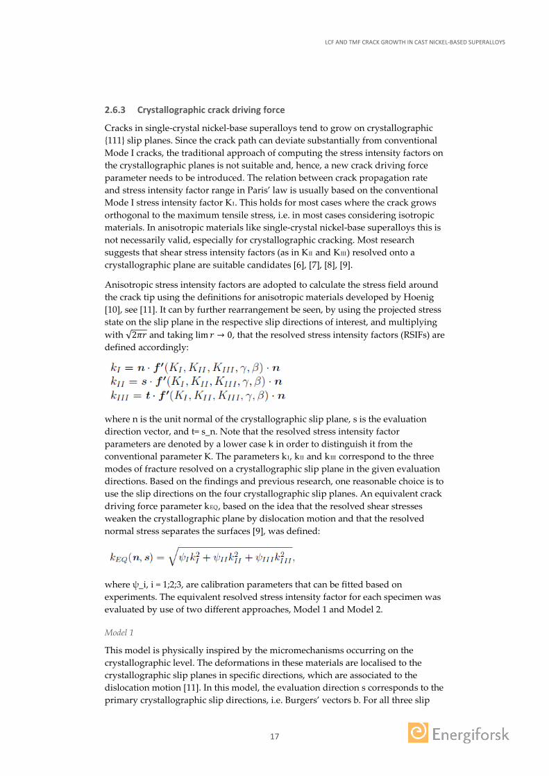
directions per plane also the negative direction vector is evaluated and the maximum value is chosen, i.e. kEQ(s = b) = max{kEQ(b), kEQ(-b)}. This is due to the assumption that the sign of the physical slip direction is of no importance. An example for the slip direction is shown in Figure 9, where the three slip directions on the (111)-crystallographic slip plane are illustrated.
Figure 9: Figure 10: Evaluation directions for Model 1. Slip directions on the (111)-plane.
Model 2
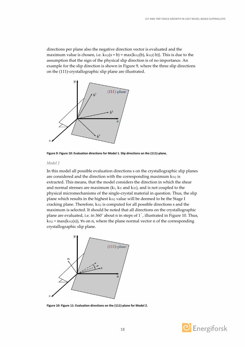
In this model all possible evaluation directions s on the crystallographic slip planes are considered and the direction with the corresponding maximum kEQ is extracted. This means, that the model considers the direction in which the shear and normal stresses are maximum (kI, kII and kIII), and is not coupled to the physical micromechanisms of the single-crystal material in question. Thus, the slip plane which results in the highest kEQ value will be deemed to be the Stage I cracking plane. Therefore, kEQ is computed for all possible directions s and the maximum is selected. It should be noted that all directions on the crystallographic plane are evaluated, i.e. in 360˚ about n in steps of 1˚, illustrated in Figure 10. Thus, kEQ = max(kEQ(s)), ∀s on n, where the plane normal vector n of the corresponding crystallographic slip plane.
Figure 10: Figure 11: Evaluation directions on the (111)-plane for Model 2.
LCF AND TMF CRACK GROWTH IN CAST NICKEL-BASED SUPERALLOYS
19
2.6.4 Handling inelasticity
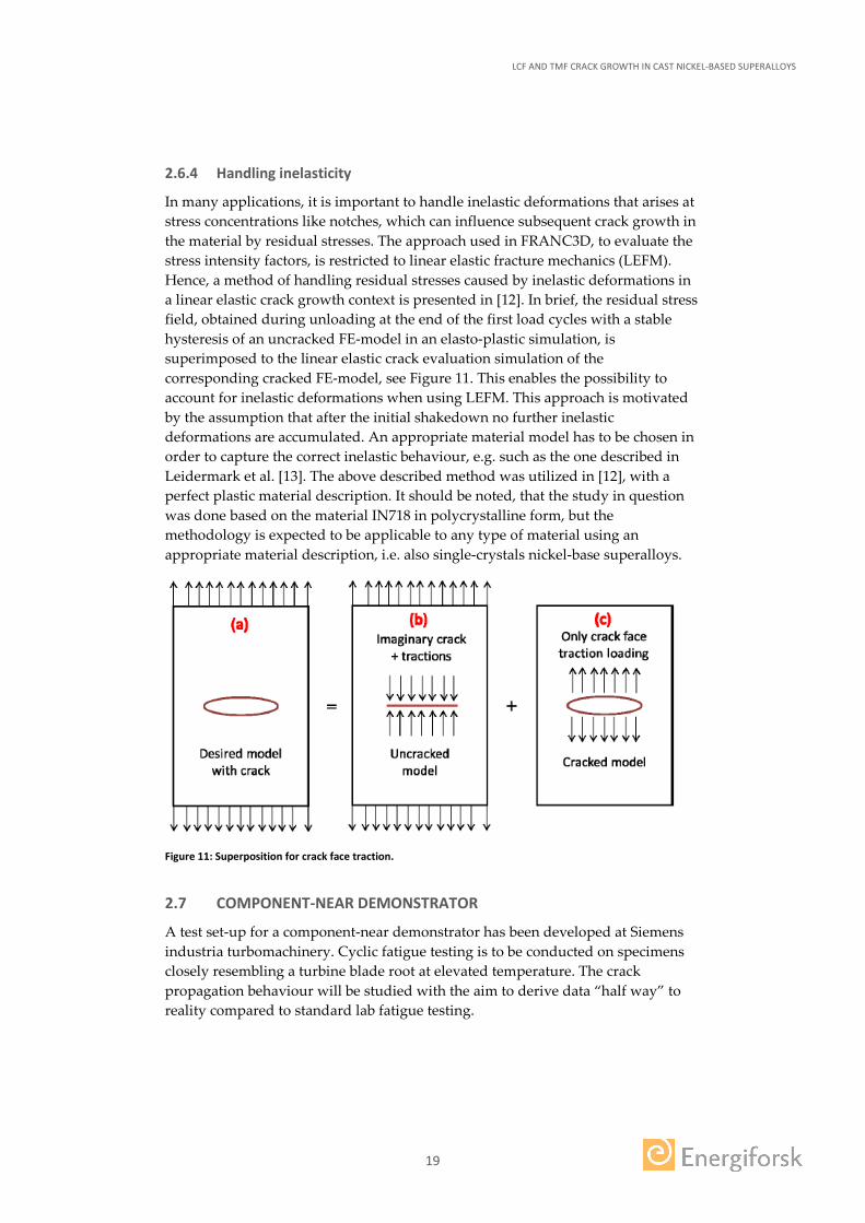
In many applications, it is important to handle inelastic deformations that arises at stress concentrations like notches, which can influence subsequent crack growth in the material by residual stresses. The approach used in FRANC3D, to evaluate the stress intensity factors, is restricted to linear elastic fracture mechanics (LEFM). Hence, a method of handling residual stresses caused by inelastic deformations in a linear elastic crack growth context is presented in [12]. In brief, the residual stress field, obtained during unloading at the end of the first load cycles with a stable hysteresis of an uncracked FE-model in an elasto-plastic simulation, is superimposed to the linear elastic crack evaluation simulation of the corresponding cracked FE-model, see Figure 11. This enables the possibility to account for inelastic deformations when using LEFM. This approach is motivated by the assumption that after the initial shakedown no further inelastic deformations are accumulated. An appropriate material model has to be chosen in order to capture the correct inelastic behaviour, e.g. such as the one described in Leidermark et al. [13]. The above described method was utilized in [12], with a perfect plastic material description. It should be noted, that the study in question was done based on the material IN718 in polycrystalline form, but the methodology is expected to be applicable to any type of material using an appropriate material description, i.e. also single-crystals nickel-base superalloys.
Figure 11: Superposition for crack face traction.
2.7 COMPONENT-NEAR DEMONSTRATOR
A test set-up for a component-near demonstrator has been developed at Siemens industria turbomachinery. Cyclic fatigue testing is to be conducted on specimens closely resembling a turbine blade root at elevated temperature. The crack propagation behaviour will be studied with the aim to derive data “half way” to reality compared to standard lab fatigue testing.
LCF AND TMF CRACK GROWTH IN CAST NICKEL-BASED SUPERALLOYS
20
3 Results and discussion
3.1 ISO THERMAL RESULTS AND ANALYSES – DCT SPECIMEN
3.1.1 DCT results at 20°C
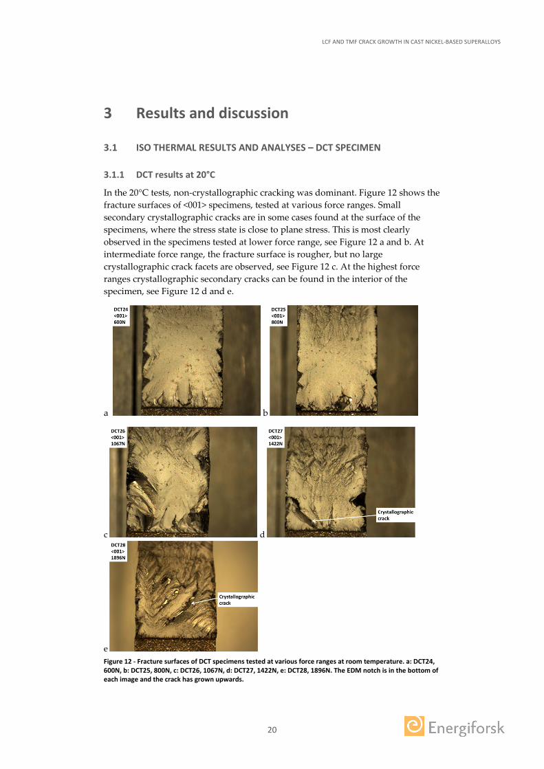
In the 20°C tests, non-crystallographic cracking was dominant. Figure 12 shows the fracture surfaces of <001> specimens, tested at various force ranges. Small secondary crystallographic cracks are in some cases found at the surface of the specimens, where the stress state is close to plane stress. This is most clearly observed in the specimens tested at lower force range, see Figure 12 a and b. At intermediate force range, the fracture surface is rougher, but no large crystallographic crack facets are observed, see Figure 12 c. At the highest force ranges crystallographic secondary cracks can be found in the interior of the specimen, see Figure 12 d and e.
a b
c d
e Figure 12 - Fracture surfaces of DCT specimens tested at various force ranges at room temperature. a: DCT24, 600N, b: DCT25, 800N, c: DCT26, 1067N, d: DCT27, 1422N, e: DCT28, 1896N. The EDM notch is in the bottom of each image and the crack has grown upwards.
LCF AND TMF CRACK GROWTH IN CAST NICKEL-BASED SUPERALLOYS
21
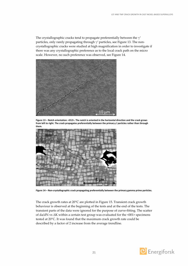
The crystallographic cracks tend to propagate preferentially between the γ′ particles, only rarely propagating through γ′ particles, see Figure 13. The non-crystallographic cracks were studied at high magnification in order to investigate if there was any crystallographic preference as to the local crack path on the micro scale. However, no such preference was observed, see Figure 14.
Figure 13 – Notch orientation: <012>. The notch is oriented in the horizontal direction and the crack grows from left to right. The crack propagates preferentially between the primary γ′ particles rather than through them.
Figure 14 – Non-crystallographic crack propagating preferentially between the primary gamma prime particles.
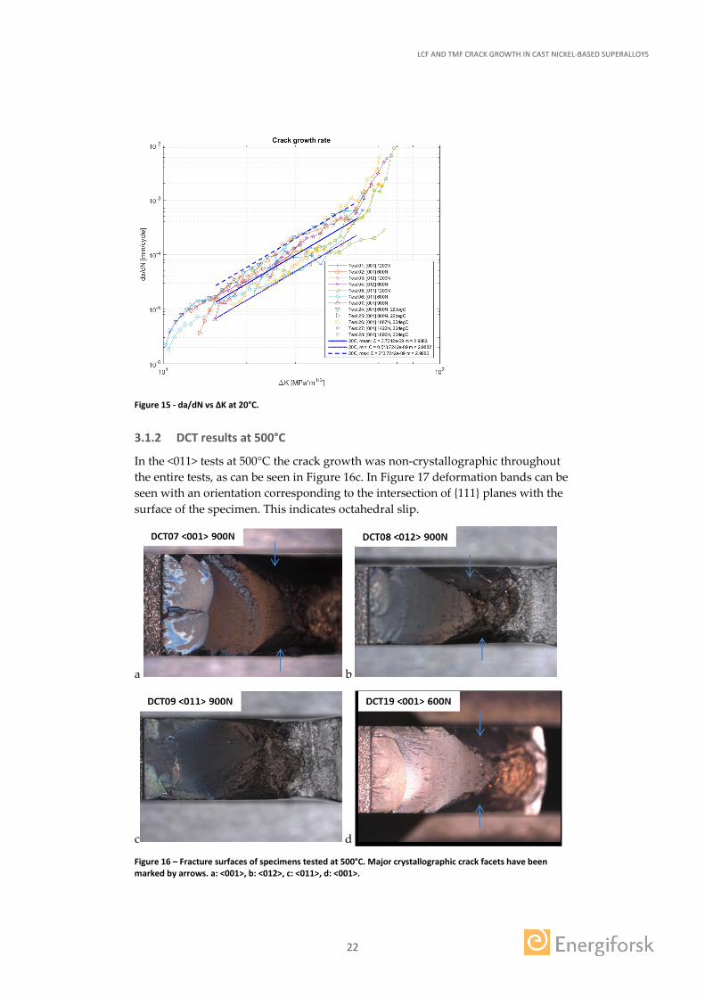
The crack growth rates at 20°C are plotted in Figure 15. Transient crack growth behaviour is observed at the beginning of the tests and at the end of the tests. The transient parts of the data were ignored for the purpose of curve-fitting. The scatter of da/dN vs ΔK within a certain test group was evaluated for the <001> specimens tested at 20°C. It was found that the maximum crack growth rate could be described by a factor of 2 increase from the average trendline.
LCF AND TMF CRACK GROWTH IN CAST NICKEL-BASED SUPERALLOYS
22
Figure 15 - da/dN vs ΔK at 20°C.
3.1.2 DCT results at 500°C
In the <011> tests at 500°C the crack growth was non-crystallographic throughout the entire tests, as can be seen in Figure 16c. In Figure 17 deformation bands can be seen with an orientation corresponding to the intersection of {111} planes with the surface of the specimen. This indicates octahedral slip.
a b
c d
Figure 16 – Fracture surfaces of specimens tested at 500°C. Major crystallographic crack facets have been marked by arrows. a: <001>, b: <012>, c: <011>, d: <001>.
LCF AND TMF CRACK GROWTH IN CAST NICKEL-BASED SUPERALLOYS
23
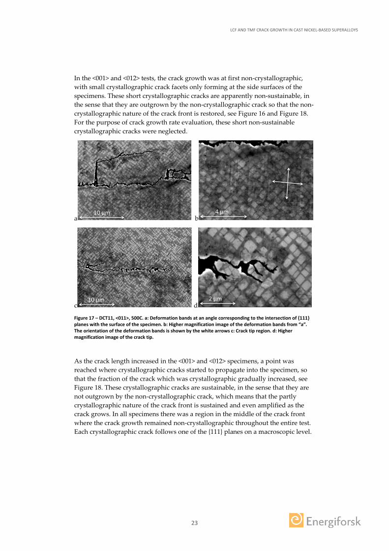
In the <001> and <012> tests, the crack growth was at first non-crystallographic, with small crystallographic crack facets only forming at the side surfaces of the specimens. These short crystallographic cracks are apparently non-sustainable, in the sense that they are outgrown by the non-crystallographic crack so that the non-crystallographic nature of the crack front is restored, see Figure 16 and Figure 18. For the purpose of crack growth rate evaluation, these short non-sustainable crystallographic cracks were neglected.
a b
c d
Figure 17 – DCT11, <011>, 500C. a: Deformation bands at an angle corresponding to the intersection of {111} planes with the surface of the specimen. b: Higher magnification image of the deformation bands from “a”. The orientation of the deformation bands is shown by the white arrows c: Crack tip region. d: Higher magnification image of the crack tip.
As the crack length increased in the <001> and <012> specimens, a point was reached where crystallographic cracks started to propagate into the specimen, so that the fraction of the crack which was crystallographic gradually increased, see Figure 18. These crystallographic cracks are sustainable, in the sense that they are not outgrown by the non-crystallographic crack, which means that the partly crystallographic nature of the crack front is sustained and even amplified as the crack grows. In all specimens there was a region in the middle of the crack front where the crack growth remained non-crystallographic throughout the entire test. Each crystallographic crack follows one of the {111} planes on a macroscopic level.
LCF AND TMF CRACK GROWTH IN CAST NICKEL-BASED SUPERALLOYS
24
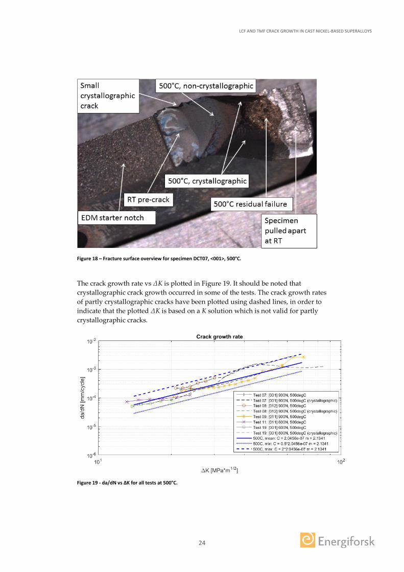
Figure 18 – Fracture surface overview for specimen DCT07, <001>, 500°C.
The crack growth rate vs ΔK is plotted in Figure 19. It should be noted that crystallographic crack growth occurred in some of the tests. The crack growth rates of partly crystallographic cracks have been plotted using dashed lines, in order to indicate that the plotted ΔK is based on a K solution which is not valid for partly crystallographic cracks.
Figure 19 - da/dN vs ΔK for all tests at 500°C.
LCF AND TMF CRACK GROWTH IN CAST NICKEL-BASED SUPERALLOYS
25
3.1.3 DCT results at 750°C
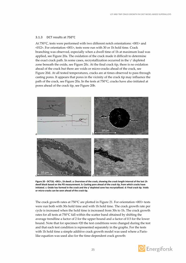
At 750°C, tests were performed with two different notch orientations: <001> and <012>. For orientation <001>, tests were run with 30 or 1h hold time. Crack branching was observed, especially when a dwell time of 1h at maximum load was applied, see Figure 20a. The oxidation of the crack made it difficult to determine the exact crack path. In some cases, recrystallization occurred in the γ′ depleted zone beneath the oxide, see Figure 20c. At the final crack tip, there is no oxidation ahead of the crack but there are voids or micro-cracks ahead of the crack, see Figure 20d. At all tested temperatures, cracks are at times observed to pass through casting pores. It appears that pores in the vicinity of the crack tip may influence the path of the crack, see Figure 20a. In the tests at 750°C, cracks have also initiated at pores ahead of the crack tip, see Figure 20b.
a b
c d
Figure 20 - DCT18, <001>, 1h dwell. a: Overview of the crack, showing the crack length interval of the last 1h dwell block based on the PD measurement. b: Casting pore ahead of the crack tip, from which cracks have initiated. c: Oxide has formed in the crack and the γ′ depleted zone has recrystallized. d: Final crack tip. Voids or micro-cracks can be seen ahead of the crack tip.
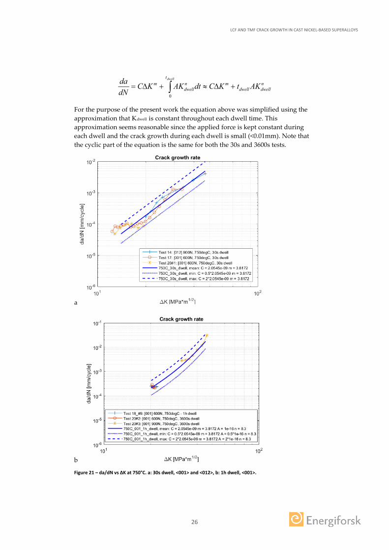
The crack growth rates at 750°C are plotted in Figure 21. For orientation <001> tests were run both with 30s hold time and with 1h hold time. The crack growth rate per cycle is increased when the hold time is increased from 30s to 1h. The crack growth rates for all tests at 750°C fall within the scatter band obtained by shifting the average trendline a factor of 2 for the upper bound and a factor of 0.5 for the lower bound. Note that for specimen #20 the test conditions were changed during the test and that each test condition is represented separately in the graphs. For the tests with 1h hold time a simple additive crack growth model was used where a Paris-like equation was used also for the time-dependent crack growth:
LCF AND TMF CRACK GROWTH IN CAST NICKEL-BASED SUPERALLOYS
26
ndwelldwell
mt
ndwell
m AKtKCdtAKKCdNda dwell
+∆≈+∆= ∫0
For the purpose of the present work the equation above was simplified using the approximation that Kdwell is constant throughout each dwell time. This approximation seems reasonable since the applied force is kept constant during each dwell and the crack growth during each dwell is small (<0.01mm). Note that the cyclic part of the equation is the same for both the 30s and 3600s tests.
a
b
Figure 21 – da/dN vs ΔK at 750°C. a: 30s dwell, <001> and <012>, b: 1h dwell, <001>.
LCF AND TMF CRACK GROWTH IN CAST NICKEL-BASED SUPERALLOYS
27
3.2 TMF CRACK GROWTH RESULTS AND ANALYSES
3.2.1 IN792: IP-TMF compared to isothermal results
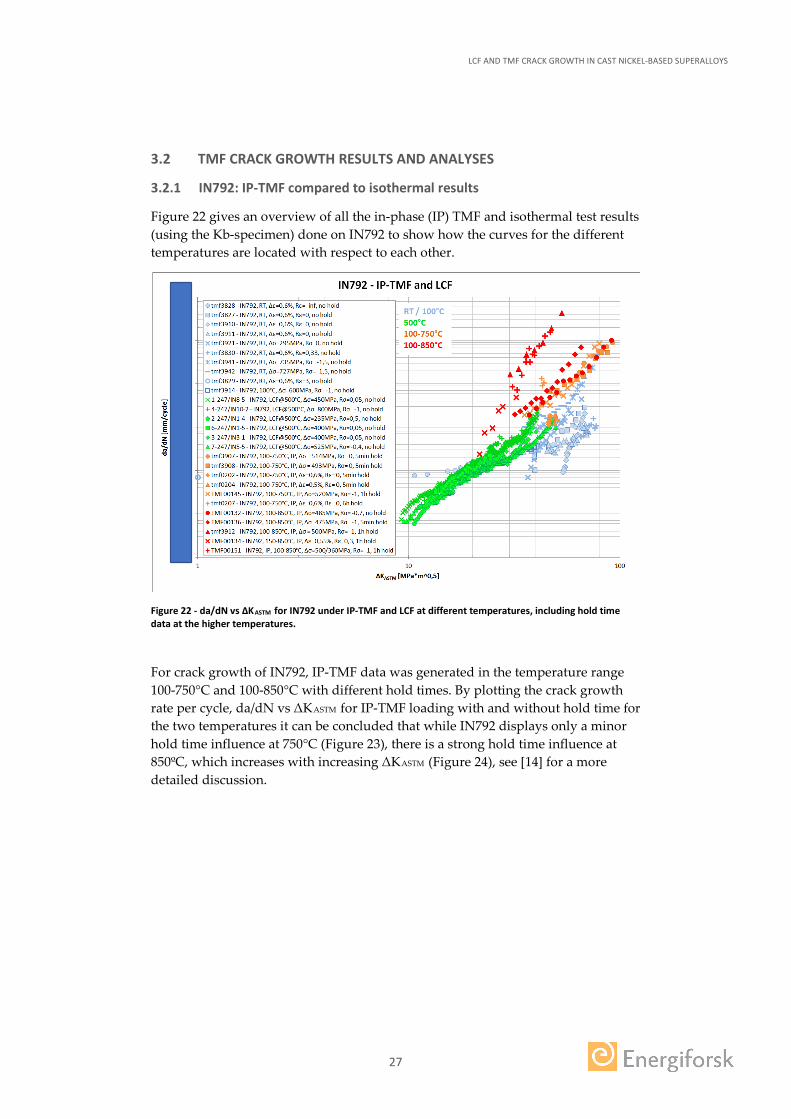
Figure 22 gives an overview of all the in-phase (IP) TMF and isothermal test results (using the Kb-specimen) done on IN792 to show how the curves for the different temperatures are located with respect to each other.
Figure 22 - da/dN vs ΔKASTM for IN792 under IP-TMF and LCF at different temperatures, including hold time data at the higher temperatures.
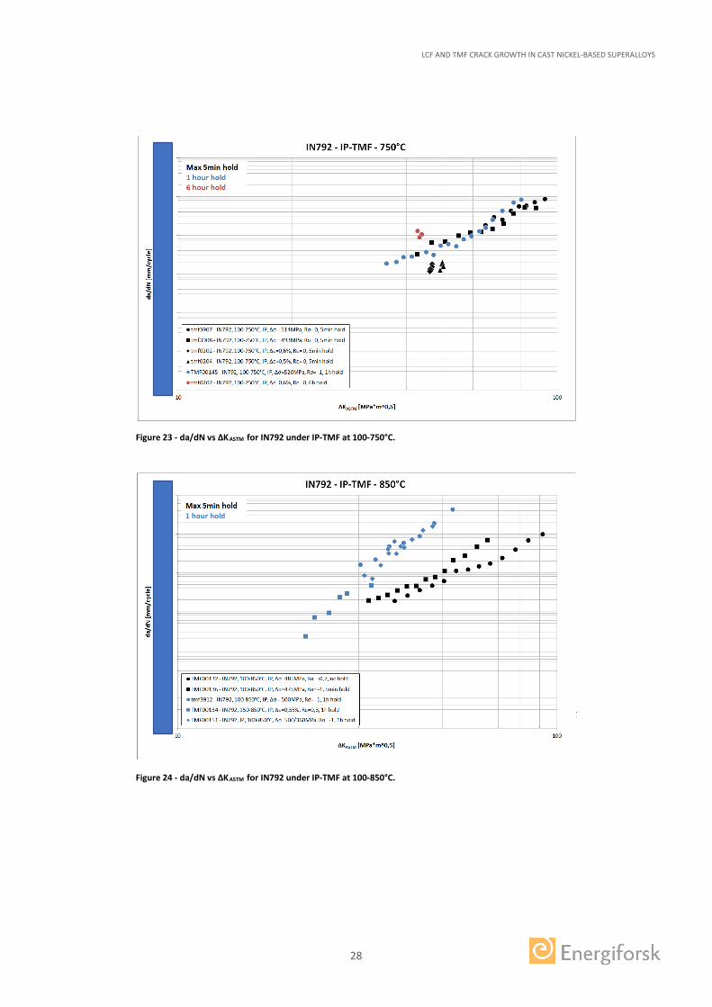
For crack growth of IN792, IP-TMF data was generated in the temperature range 100-750°C and 100-850°C with different hold times. By plotting the crack growth rate per cycle, da/dN vs ΔKASTM for IP-TMF loading with and without hold time for the two temperatures it can be concluded that while IN792 displays only a minor hold time influence at 750°C (Figure 23), there is a strong hold time influence at 850ºC, which increases with increasing ΔKASTM (Figure 24), see [14] for a more detailed discussion.
LCF AND TMF CRACK GROWTH IN CAST NICKEL-BASED SUPERALLOYS
28
Figure 23 - da/dN vs ΔKASTM for IN792 under IP-TMF at 100-750°C.
Figure 24 - da/dN vs ΔKASTM for IN792 under IP-TMF at 100-850°C.
LCF AND TMF CRACK GROWTH IN CAST NICKEL-BASED SUPERALLOYS
29
3.2.2 IN792: OP-TMF
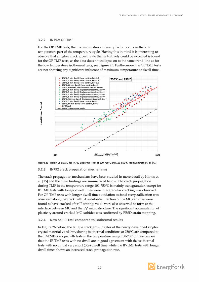
For the OP TMF tests, the maximum stress intensity factor occurs in the low temperature part of the temperature cycle. Having this in mind it is interesting to observe that a higher crack growth rate than intuitively could be expected is found for the OP TMF tests, as the data does not collapse on to the same trend-line as for the low temperature isothermal tests, see Figure 25. Furthermore, the OP TMF tests are not showing any significant influence of maximum temperature or dwell time.
Figure 25 - da/dN vs ΔKASTM for IN792 under OP-TMF at 100-750°C and 100-850°C. From Almroth et. al. [41]
3.2.3 IN792 crack propagation mechanisms
The crack propagation mechanisms have been studied in more detail by Kontis et. al. [15] and the main findings are summarized below. The crack propagation during TMF in the temperature range 100-750°C is mainly transgranular, except for IP TMF tests with longer dwell times were intergranular cracking was observed. For OP TMF tests with longer dwell times oxidation assisted recrystallization was observed along the crack path. A substantial fraction of the MC carbides were found to have cracked after IP testing; voids were also observed to form at the interface between MC and the γ/γ’ microstructure. The significant accumulation of plasticity around cracked MC carbides was confirmed by EBSD strain mapping.
3.2.4 New SX: IP-TMF compared to isothermal results
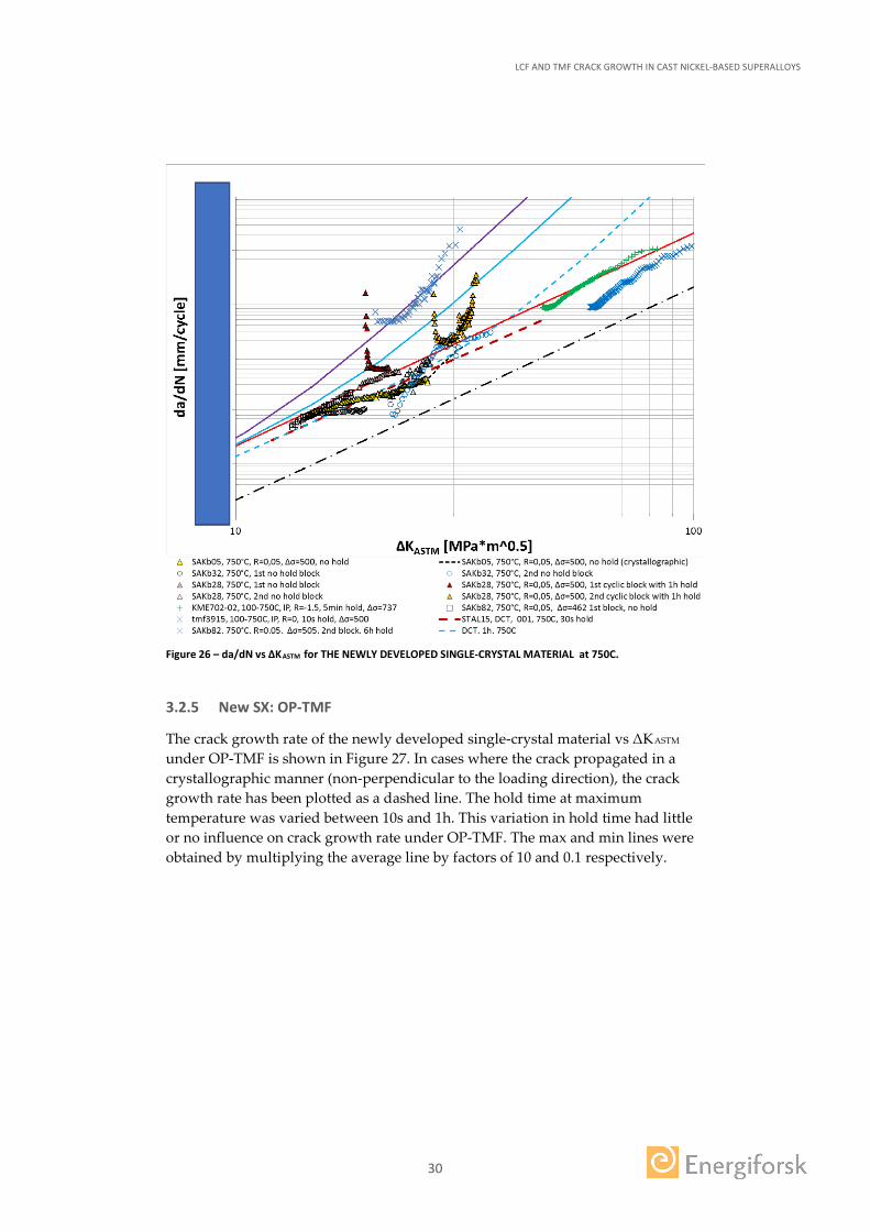
In Figure 26 below, the fatigue crack growth rates of the newly developed single-crystal material vs ΔKASTM during isothermal conditions at 750°C are compared to the IP-TMF crack growth tests in the temperature range 100-750°C. One can see that the IP-TMF tests with no dwell are in good agreement with the isothermal tests with no or just very short (30s) dwell time while the IP-TMF tests with longer dwell times shows an increased crack propagation rate.
LCF AND TMF CRACK GROWTH IN CAST NICKEL-BASED SUPERALLOYS
30
Figure 26 – da/dN vs ΔKASTM for THE NEWLY DEVELOPED SINGLE-CRYSTAL MATERIAL at 750C.
3.2.5 New SX: OP-TMF
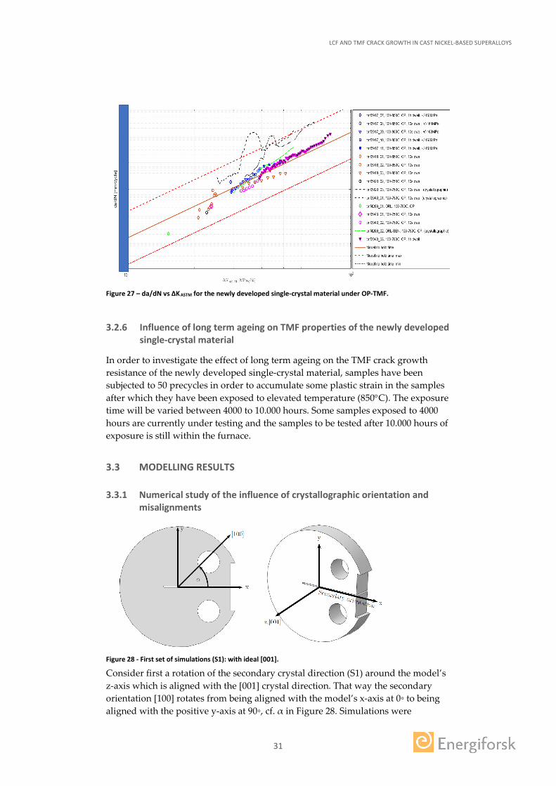
The crack growth rate of the newly developed single-crystal material vs ΔKASTM under OP-TMF is shown in Figure 27. In cases where the crack propagated in a crystallographic manner (non-perpendicular to the loading direction), the crack growth rate has been plotted as a dashed line. The hold time at maximum temperature was varied between 10s and 1h. This variation in hold time had little or no influence on crack growth rate under OP-TMF. The max and min lines were obtained by multiplying the average line by factors of 10 and 0.1 respectively.
LCF AND TMF CRACK GROWTH IN CAST NICKEL-BASED SUPERALLOYS
31
Figure 27 – da/dN vs ΔKASTM for the newly developed single-crystal material under OP-TMF.
3.2.6 Influence of long term ageing on TMF properties of the newly developed single-crystal material
In order to investigate the effect of long term ageing on the TMF crack growth resistance of the newly developed single-crystal material, samples have been subjected to 50 precycles in order to accumulate some plastic strain in the samples after which they have been exposed to elevated temperature (850°C). The exposure time will be varied between 4000 to 10.000 hours. Some samples exposed to 4000 hours are currently under testing and the samples to be tested after 10.000 hours of exposure is still within the furnace.
3.3 MODELLING RESULTS
3.3.1 Numerical study of the influence of crystallographic orientation and misalignments
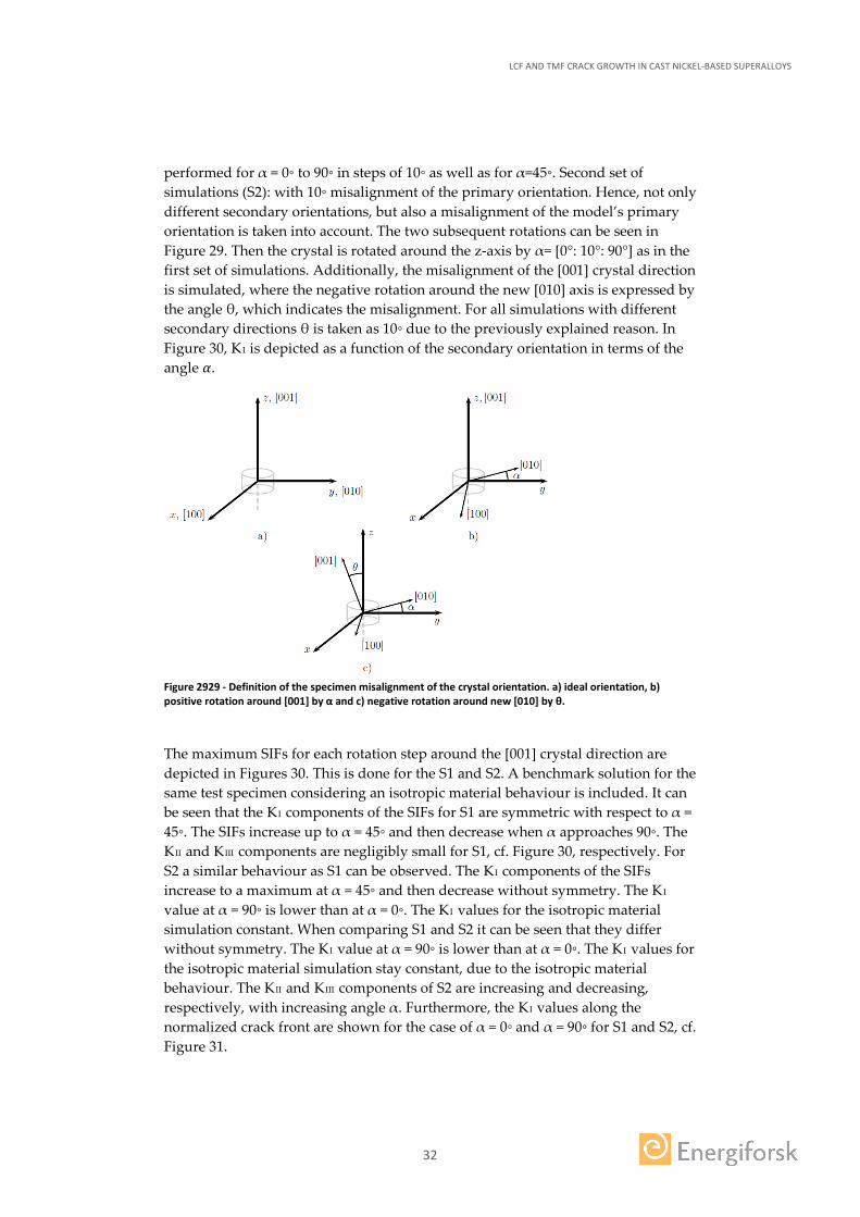
Figure 28 - First set of simulations (S1): with ideal [001].
Consider first a rotation of the secondary crystal direction (S1) around the model’s z-axis which is aligned with the [001] crystal direction. That way the secondary orientation [100] rotates from being aligned with the model’s x-axis at 0◦ to being aligned with the positive y-axis at 90◦, cf. α in Figure 28. Simulations were
LCF AND TMF CRACK GROWTH IN CAST NICKEL-BASED SUPERALLOYS
32
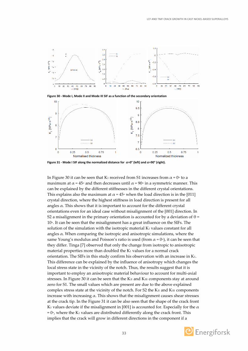
performed for α = 0◦ to 90◦ in steps of 10◦ as well as for α=45◦. Second set of simulations (S2): with 10◦ misalignment of the primary orientation. Hence, not only different secondary orientations, but also a misalignment of the model’s primary orientation is taken into account. The two subsequent rotations can be seen in Figure 29. Then the crystal is rotated around the z-axis by α= [0°: 10°: 90°] as in the first set of simulations. Additionally, the misalignment of the [001] crystal direction is simulated, where the negative rotation around the new [010] axis is expressed by the angle θ, which indicates the misalignment. For all simulations with different secondary directions θ is taken as 10◦ due to the previously explained reason. In Figure 30, KI is depicted as a function of the secondary orientation in terms of the angle 𝛼𝛼.
Figure 2929 - Definition of the specimen misalignment of the crystal orientation. a) ideal orientation, b) positive rotation around [001] by α and c) negative rotation around new [010] by θ.
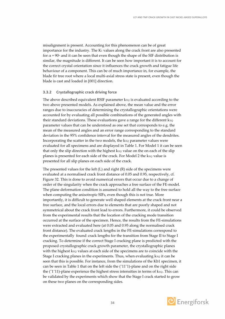
The maximum SIFs for each rotation step around the [001] crystal direction are depicted in Figures 30. This is done for the S1 and S2. A benchmark solution for the same test specimen considering an isotropic material behaviour is included. It can be seen that the KI components of the SIFs for S1 are symmetric with respect to α = 45◦. The SIFs increase up to α = 45◦ and then decrease when α approaches 90◦. The KII and KIII components are negligibly small for S1, cf. Figure 30, respectively. For S2 a similar behaviour as S1 can be observed. The KI components of the SIFs increase to a maximum at α = 45◦ and then decrease without symmetry. The KI value at α = 90◦ is lower than at α = 0◦. The KI values for the isotropic material simulation constant. When comparing S1 and S2 it can be seen that they differ without symmetry. The KI value at α = 90◦ is lower than at α = 0◦. The KI values for the isotropic material simulation stay constant, due to the isotropic material behaviour. The KII and KIII components of S2 are increasing and decreasing, respectively, with increasing angle α. Furthermore, the KI values along the normalized crack front are shown for the case of α = 0◦ and α = 90◦ for S1 and S2, cf. Figure 31.
LCF AND TMF CRACK GROWTH IN CAST NICKEL-BASED SUPERALLOYS
33
Figure 30 - Mode I, Mode II and Mode III SIF as a function of the secondary orientation
Figure 31 - Mode I SIF along the normalized distance for 𝜶𝜶=0° (left) and 𝜶𝜶=90° (right).
In Figure 30 it can be seen that KI received from S1 increases from α = 0◦ to a maximum at α = 45◦ and then decreases until α = 90◦ in a symmetric manner. This can be explained by the different stiffnesses in the different crystal orientations. This explains also the maximum at α = 45◦ when the load direction is in the [011] crystal direction, where the highest stiffness in load direction is present for all angles α. This shows that it is important to account for the different crystal orientations even for an ideal case without misalignment of the [001] direction. In S2 a misalignment in the primary orientation is accounted for by a deviation of θ = 10◦. It can be seen that the misalignment has a great influence on the SIFs. The solution of the simulation with the isotropic material KI values constant for all angles α. When comparing the isotropic and anisotropic simulations, where the same Young’s modulus and Poisson’s ratio is used (from α = 0◦), it can be seen that they differ. Tinga [7] observed that only the change from isotropic to anisotropic material properties more than doubled the KI values for a normal crack orientation. The SIFs in this study confirm his observation with an increase in KI. This difference can be explained by the influence of anisotropy which changes the local stress state in the vicinity of the notch. Thus, the results suggest that it is important to employ an anisotropic material behaviour to account for multi-axial stresses. In Figure 30 it can be seen that the KII and KIII components stay at around zero for S1. The small values which are present are due to the above explained complex stress state at the vicinity of the notch. For S2 the KII and KIII components increase with increasing α. This shows that the misalignment causes shear stresses at the crack tip. In the Figure 31 it can be also seen that the shape of the crack front KI values deviate if the misalignment in [001] is accounted for. Especially for the α = 0◦, where the KI values are distributed differently along the crack front. This implies that the crack will grow in different directions in the component if a
LCF AND TMF CRACK GROWTH IN CAST NICKEL-BASED SUPERALLOYS
34
misalignment is present. Accounting for this phenomenon can be of great importance for the industry. The KI values along the crack front are also presented for α = 90◦ and it can be seen that even though the shape of the SIF distribution is similar, the magnitude is different. It can be seen how important it is to account for the correct crystal orientation since it influences the crack growth and fatigue life behaviour of a component. This can be of much importance in, for example, the blade fir tree root where a local multi-axial stress state is present, even though the blade is cast and loaded in [001] direction.
3.3.2 Crystallographic crack driving force
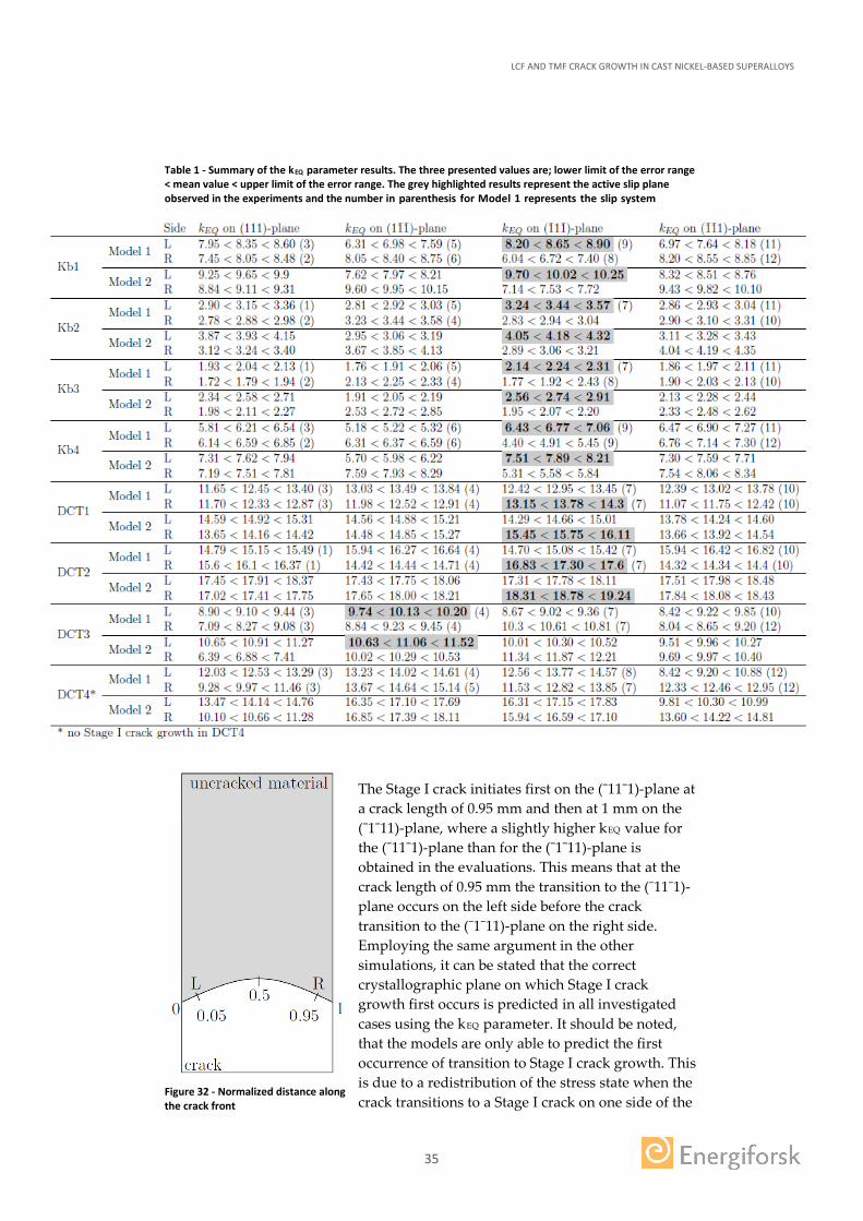
The above described equivalent RSIF parameter kEQ is evaluated according to the two above presented models. As explained above, the mean value and the error ranges due to inaccuracies of determining the crystallographic orientations were accounted for by evaluating all possible combinations of the generated angles with their standard deviations. These evaluations gave a range for the different kEQ parameter values that can be understood as one set that corresponds to e.g. the mean of the measured angles and an error range corresponding to the standard deviation in the 95% confidence interval for the measured angles of the dendrites. Incorporating the scatter in the two models, the kEQ parameter values were evaluated for all specimens and are displayed in Table 1. For Model 1 it can be seen that only the slip direction with the highest kEQ value on the on each of the slip planes is presented for each side of the crack. For Model 2 the kEQ value is presented for all slip planes on each side of the crack.
The presented values for the left (L) and right (R) side of the specimens were evaluated at a normalised crack front distance of 0.05 and 0.95, respectively, cf. Figure 32. This is done to avoid numerical errors that occur due to a change of order of the singularity when the crack approaches a free surface of the FE-model. The plane deformation condition is assumed to hold all the way to the free surface when computing the anisotropic SIFs, even though this is not true. More importantly, it is difficult to generate well shaped elements at the crack front near a free surface, and the local errors due to elements that are poorly shaped and not symmetrical about the crack front lead to errors. Furthermore, it could be observed from the experimental results that the location of the cracking mode transition occurred at the surface of the specimen. Hence, the results from the FE-simulations were extracted and evaluated here (at 0.05 and 0.95 along the normalised crack front distance). The evaluated crack lengths in the FE-simulations correspond to the experimentally found crack lengths for the transition from Stage II to Stage I cracking. To determine if the correct Stage I cracking plane is predicted with the proposed crystallographic crack growth parameter, the crystallographic planes with the highest kEQ values at each side of the specimens are to coincide with the Stage I cracking planes in the experiments. Thus, when evaluating kEQ it can be seen that this is possible. For instance, from the simulations of the Kb1 specimen, it can be seen in Table 1 that on the left side the (¯11¯1)-plane and on the right side the (¯1¯11)-plane experience the highest stress intensities in terms of kEQ. This can be validated by the experiments which show that the Stage I crack started to grow on these two planes on the corresponding sides.
LCF AND TMF CRACK GROWTH IN CAST NICKEL-BASED SUPERALLOYS
35
Table 1 - Summary of the kEQ parameter results. The three presented values are; lower limit of the error range < mean value < upper limit of the error range. The grey highlighted results represent the active slip plane observed in the experiments and the number in parenthesis for Model 1 represents the slip system
The Stage I crack initiates first on the (¯11¯1)-plane at a crack length of 0.95 mm and then at 1 mm on the (¯1¯11)-plane, where a slightly higher kEQ value for the (¯11¯1)-plane than for the (¯1¯11)-plane is obtained in the evaluations. This means that at the crack length of 0.95 mm the transition to the (¯11¯1)-plane occurs on the left side before the crack transition to the (¯1¯11)-plane on the right side. Employing the same argument in the other simulations, it can be stated that the correct crystallographic plane on which Stage I crack growth first occurs is predicted in all investigated cases using the kEQ parameter. It should be noted, that the models are only able to predict the first occurrence of transition to Stage I crack growth. This is due to a redistribution of the stress state when the crack transitions to a Stage I crack on one side of the
Figure 32 - Normalized distance along the crack front
LCF AND TMF CRACK GROWTH IN CAST NICKEL-BASED SUPERALLOYS
36
specimen, since this changes the crack geometry and the stress state. Thus, the presented framework is only valid for the prediction of the Stage I cracking plane of the first transition from Stage II to Stage I cracking or when the transition occurs almost simultaneously, i.e. the stress state and crack shape do not change in any greater extent.
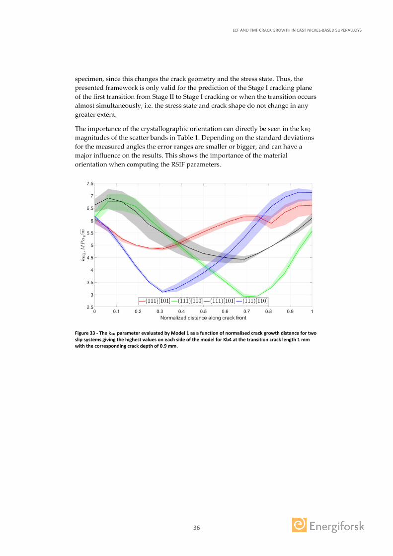
The importance of the crystallographic orientation can directly be seen in the kEQ magnitudes of the scatter bands in Table 1. Depending on the standard deviations for the measured angles the error ranges are smaller or bigger, and can have a major influence on the results. This shows the importance of the material orientation when computing the RSIF parameters.
Figure 33 - The kEQ parameter evaluated by Model 1 as a function of normalised crack growth distance for two slip systems giving the highest values on each side of the model for Kb4 at the transition crack length 1 mm with the corresponding crack depth of 0.9 mm.
LCF AND TMF CRACK GROWTH IN CAST NICKEL-BASED SUPERALLOYS
37
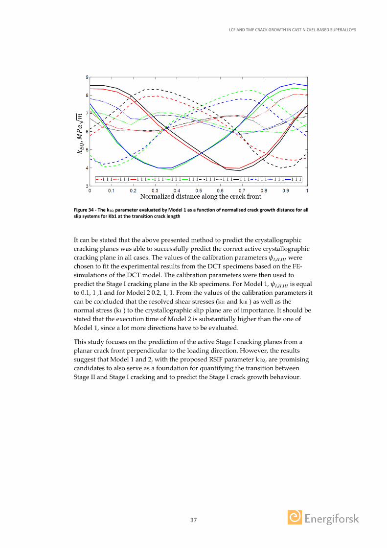
Figure 34 - The kEQ parameter evaluated by Model 1 as a function of normalised crack growth distance for all slip systems for Kb1 at the transition crack length
It can be stated that the above presented method to predict the crystallographic cracking planes was able to successfully predict the correct active crystallographic cracking plane in all cases. The values of the calibration parameters 𝜓𝜓𝐼𝐼,𝐼𝐼𝐼𝐼,𝐼𝐼𝐼𝐼𝐼𝐼 were chosen to fit the experimental results from the DCT specimens based on the FE-simulations of the DCT model. The calibration parameters were then used to predict the Stage I cracking plane in the Kb specimens. For Model 1, 𝜓𝜓𝐼𝐼,𝐼𝐼𝐼𝐼,𝐼𝐼𝐼𝐼𝐼𝐼 is equal to 0.1, 1 ,1 and for Model 2 0.2, 1, 1. From the values of the calibration parameters it can be concluded that the resolved shear stresses (kII and kIII ) as well as the normal stress (kI ) to the crystallographic slip plane are of importance. It should be stated that the execution time of Model 2 is substantially higher than the one of Model 1, since a lot more directions have to be evaluated.
This study focuses on the prediction of the active Stage I cracking planes from a planar crack front perpendicular to the loading direction. However, the results suggest that Model 1 and 2, with the proposed RSIF parameter kEQ, are promising candidates to also serve as a foundation for quantifying the transition between Stage II and Stage I cracking and to predict the Stage I crack growth behaviour.
LCF AND TMF CRACK GROWTH IN CAST NICKEL-BASED SUPERALLOYS
38
4 Conclusions
The main conclusions from the experimental work are summarized below:
• From the isothermal tests the following conclusion has been drawn:
o The crack growth rate increases with increasing testing temperature in the tested temperature range of 20–750 °C.
o In the 20 °C tests, non-crystallographic crack growth was dominant. Crystallographic cracking occurred locally at the side surfaces of the specimens. At the highest stress levels in ⟨0 0 1⟩ specimens, crystallographic secondary cracks could also be found in the interior of the specimens.
o For non-crystallographic cracks propagating in Mode I, the difference in non-crystallographic crack growth rate between the different orientations appears to be smaller than the scatter of the results for a certain crystal orientation.
o The propensity for crystallographic crack growth was highest at the intermediate testing temperature of 500 °C. This behaviour could not be explained by confinement of inelastic strains to the γ matrix based on the temperature dependences of the critical resolved shear stress of the γ and γ′ phases respectively. The reason for the noncrystallographic nature of the crack growth at 20 °C remains a topic for future investigation.
o In the 500 °C tests partly crystallographic crack growth was observed in the ⟨0 0 1⟩ and ⟨0 1 2⟩ tests, but not in the ⟨0 1 1⟩ tests. The crystallographic cracks initiated at the side surfaces of the specimens, where the stress state was close to plane stress. There was a region in the middle of the crack front where the crack growth remained non-crystallographic throughout the entire test.
o In the present tests at 750 °C da/dN was observed to increase with increasing hold time at maximum load. The hold time influence decreased with decreasing ΔK. For ΔK < 30 MPa∗m0.5 (da/dN < 10−3 mm/cycle), no significant difference in da/dN at 750 °C could be observed between 1 h dwell and 30 s dwell time.
• From the TMF crack propagation tests the following conclusion has been drawn:
o Material data for the cast polycrystalline nickel-based superalloy IN792 and the newly developed single-crystal material have been generated by TMF crack growth testing with and without long dwell times. A rigid SEN test specimen capable of negative R-ratio loading has been used.
o Under IP-TMF conditions for IN792, a transition from transgranular to intergranular crack propagation was observed as the dwell time increases.
LCF AND TMF CRACK GROWTH IN CAST NICKEL-BASED SUPERALLOYS
39
o IP crack growth rate increase with increasing temperature and length of the dwell, as expected. However, OP crack growth is not to be affected by temperature and dwell if plotted versus ΔKASTM. OP crack growth is faster than isothermal low temperature data when plotted versus ΔKASTM.
o The crack propagation rates for the newly developed single-crystal material shows similar trends as for the polycrystalline superalloy IN792.
The main conclusions from the modelling work are:
• An effective approach to handle inelastic deformations using linear elastic fracture mechanics has been displayed. The residual stress state from an elastic-plastic FE-analysis of an uncracked model is superimposed on a linear elastic crack evaluation of the corresponding cracked model.
• The stress state in a single-crystal component has to be accounted for by an appropriate material model, especially in the vicinity of a notched feature where the complexity increases and the likeliness of crack initiation and subsequent propagation increases.
• The crystal orientation is important when evaluating the stress intensity factors, since an anisotropic effect is present in the component. Furthermore, it is important to account for the misalignments in a cast component, since the orientation will have a major influence on the crack propagation behaviour.
• The developed crystallographic crack driving force parameter kEQ is able to successfully predict the active crystallographic cracking plane after transitioning from an initially global Mode I crack.
• This developed crystallographic crack driving force parameter can be used in an industrial crack growth assessment procedure that will contribute in making life predictions more accurate. Hence, leading to less conservative safety margins.
LCF AND TMF CRACK GROWTH IN CAST NICKEL-BASED SUPERALLOYS
40
5 Literature references
[1] Reed RC, Moverare J, Sato A, Karlsson F, Hasselqvist M. A New Single-crystal Superalloy for Power Generation Applications, in: Superalloys 2012. 2012.
[2] Ewest D, Almroth P, Sjödin B, Simonsson K, Leidermark D, Moverare J, Int J Fatigue 2016;92:61.
[3] Abaqus, ABAQUS 6.12 Documentation. Providence, USA: Dassault Systèmes, 2014.
[4] FRANC3D, FRANC3D Reference Manual. Ithaca, USA: Fracture Analysis Consultants Inc., 2016.
[5] Busse C., Gustafsson D., Rasmusson P., Sjödin B., Moverare J.J., Simonsson K., Leidermark D., Three-Dimensional LEFM Prediction of Fatigue Crack Propagation in a Gas Turbine Disk Material at Component Near Conditions (2016) Journal of Engineering for Gas Turbines and Power, 138 (4), pp. 042506-1-8.
[6] Busse C., Loureiro Homs J., Gustafsson D., Palmert F., Sjödin B., Moverare J.J., Simonsson K., Leidermark D., A Finite Element Study of the Effect of Crystal Orientation and Misalignment on the Crack Driving Force in a Single-Crystal Superalloy (2016) ASME Turbo Expo 2016: Turbine Technical Conference and Exposition, 7A, pp. V07AT28A002.
[7] Tinga T., “Stress intensity factors and crack propagation in a single-crystal nickel-based superalloy”, Engineering Fracture Mechanics 73, 2006.
[8] Telesman J., Ghosn L.J., Fatigue crack growth behavior of PWA 1484 single crystal superalloy at elevated temperatures, Journal of Engineering for Gas Turbines and Power 118 (1996) 399–405.
[9] Anderson T.L., Fracture mechanics: fundamentals and applications, 3rd ed., CRC Press, Boca Raton, 1995.
[10] Hoenig A., Near-tip behavior of a crack in a plane anisotropic elastic body, Engineering Fracture Mechanics 16 (1982) 393–403.
[11] Busse C., Palmert F., Sjödin B., Almroth P., Gustafsson D., Simonsson K., Leidermark D. (2017). Prediction of crystallographic cracking planes in a single-crystal nickel-base superalloy. To be submitted.
[12] Pope DP, Ezz SS, Mechanical properties of Ni3Al and nickel-base alloys with high volume fraction of gamma prime, International metals reviews 29 (1984) 136–167.
[13] Leidermark D, Moverare J, Simonsson K, Sjöström S, Johansson S. Comput Mater Sci., 2009;47:366.
[14] Almroth P., Gustafsson D., On thermomechanical fatigue crack growth analysis in gas turbine blading in a 3D finite element context, (2017) Conference: LCF8, Dresden, Germany.
[15] Kontis P., Collins D.M., Johansson s., Wilkinson A.J., Moverare J.J., Reed R.C., Crack initiation and propagation during thermal-mechanical fatigue of IN792: Effect of dwell time (2016) Superalloys 2016: Proceeding of the 13th International symposioum on Superalloys, pp. 763-772.
LCF AND TMF CRACK GROWTH IN CAST NICKEL-BASED SUPERALLOYS
41
6 Publications
Journal and conference papers published within the KME702-project:
1. Busse C., Gustafsson D., Rasmusson P., Sjödin B., Moverare J.J., Simonsson K., Leidermark D., Three-Dimensional LEFM Prediction of Fatigue Crack Propagation in a Gas Turbine Disk Material at Component Near Conditions (2016) Journal of Engineering for Gas Turbines and Power, 138 (4), pp. 042506-1-8.
2. Busse C., Loureiro Homs J., Gustafsson D., Palmert F., Sjödin B., Moverare J.J., Simonsson K., Leidermark D., A Finite Element Study of the Effect of Crystal Orientation and Misalignment on the Crack Driving Force in a Single-Crystal Superalloy (2016) ASME Turbo Expo 2016: Turbine Technical Conference and Exposition, 7A, pp. V07AT28A002.
3. Kontis P., Collins D.M., Johansson s., Wilkinson A.J., Moverare J.J., Reed R.C., Crack initiation and propagation during thermal-mechanical fatigue of IN792: Effect of dwell time (2016) Superalloys 2016: Proceeding of the 13th International symposioum on Superalloys, pp. 763-772.
4. Busse C., Palmert F., Sjödin B., Almroth P., Gustafsson D., Simonsson K., Leidermark D. (2017). Prediction of crystallographic cracking planes in a single-crystal nickel-base superalloy. To be submitted.
5. Palmert F., Moverare J., Gustafsson D., Busse C., Fatigue crack growth behaviour of an alternative single-crystal nickel base superalloy (2018) International Journal of Fatigue, 109, pp. 166-181.
6. Almroth P., Gustafsson D., On thermomechanical fatigue crack growth analysis in gas turbine blading in a 3D finite element context, (2017) Conference: LCF8, Dresden, Germany.
7. Westin P., SGT-800B1/B2/B2M Blade 1 and disc 1: Component Near Testing – Mechanical Integrity Calculations, Siemens Industrial Turbomachinery AB, 1CS167643
8. Segersäll M., Kontis P., Pedrazzini S., Bagot P.A.J., Moody M.P., Moverare J.J., Reed R.C., Thermal-mechanical fatigue behaviour of a new single-crystal superalloy: Effects of Si and Re alloying (2015) Acta Materialia 95,12102, pp. 456-467
9. Segersäll M., Leidermark D., Moverare J.J., Influence of crystal orientation on the thermomechanical fatigue behaviour in a single-crystal superalloy (2015) Materials Science and Engineering A 623, pp. 68-77
10. Leidermark D., Moverare J., Comparative Analysis of Stress Relaxation and Creep in a Single-Crystal Superalloy (2016) ASME Turbo Expo 2016: Turbine Technical Conference and Exposition, 7A, pp. V07AT28A005.
11. Busse C, Aspects of Crack Growth in Single-Crystal Nickel-Base Superalloys, (2017) Licentiate thesis, Linköping University.
LCF AND TMF CRACK GROWTH IN CAST NICKEL-BASED SUPERALLOYS
42
Svensk titel på projektet
LCF och TMF spricktillväxt i gjutna nickelbaserade superlegeringar
English project title
LCF and TMF crack growth in cast nickel-based superalloys
Universitet/högskola/företag Avdelning/institution
Linköpings universitet Konstruktionsmaterial & Mekanik och Hållfasthetslära
Adress
58183 Linköping
Namn på projektledare
Johan Moverare
Namn på ev övriga projektdeltagare
Daniel Leidermark, Christian Busse, Frans Palmert, Kjell Simonsson, David Gustafsson, Björn Sjödin
Nyckelord: 5-7 st
Sprickpropagering, Enkristallint material, Polykristallint material, Högtemperaturmekanik, Termomekaniskutmattning, Kristallografiskspricktillväxt, Nickelbaserade superlegeringar

LCF AND TMF CRACK GROWTH IN CAST NICKEL-BASED SUPERALLOYS The crack growth behaviour has been investigated for cast nickel-based super- alloys. At room temperatures, non-crystallographic crack growth was domi-nant but crystallographic cracking occurred locally at the side surfaces of the specimens. The propensity for crystallographic crack growth increased at the intermediate testing temperature of 500 °C but was also found to be depen-dent of the orientation of the single crystal alloy. Crystallographic crack growth was observed in the ⟨0 0 1⟩ and ⟨0 1 2⟩ tests, but not in the ⟨0 1 1⟩ tests. The crystallographic cracks initiated at the side surfaces of the specimens, where the stress state was close to plane stress. There was a region in the middle of the crack front where the crack growth remained non-crystallographic throug-hout the entire test. At 750 °C the crack growth rate da/dN was observed to increase with increasing hold time at maximum load. Thermomechanical crack growth testing was also performed for both the conventional alloy IN792 and a newly developed single crystal superalloy and the results were compared to the isothermal tests.
From the modelling perspective, the key research result is the developed crys-tallographic crack driving force parameter. This can be used to define the be-haviour and growth of the crystallographic crack. In practice, this parameter enables the user to be able to predict when, where and how a crystallographic crack grows in a single-crystal nickel-base superalloy material.
Energiforsk is the Swedish Energy Research Centre – an industrially owned body dedicated to meeting the common energy challenges faced by industries, authorities and society. Our vision is to be hub of Swedish energy research and our mission is to make the world of energy smarter!
![Influence of minimum temperature on the … round bars that satisfy the ASTM standard for LCF testing (ASTM E606-04) [6]. The axis of all ... Before beginning the TMF cycling, stress-free](https://img.pdfslide.us/doc/110x75/5afa20587f8b9ae92b8d4ed3/influence-of-minimum-temperature-on-the-round-bars-that-satisfy-the-astm-standard.jpg)