Embed Size (px)
Citation preview
Linköping Studies in Science and TechnologyLicentiate Thesis No. 1568
Nickel-Based Single-CrystalSuperalloys
- the crystal orientation influence on high
temperature properties
Mikael Segersäll
LIU–TEK–LIC–2013:2
Division of Engineering MaterialsDepartment of Management and Engineering
Linköping University, SE-58183, Linköping, Swedenhttp://www.liu.se
Linköping, March 2013
Opponent: Professor Roger C. Reed, University of Oxford, United KingdomDefend date: March 22, 2013Room: C3, Linköping University
Thesis cover: Design by Maria J. Segersäll
Printed by:LiU-Tryck, Linköping, Sweden, 2013ISBN 978-91-7519-709-8ISSN 0280-7971
Distributed by:Division of Engineering Materials, Department of Management and EngineeringLinköping UniversitySE-58183, Linköping, Sweden
© 2013 Mikael Segersäll
This document was prepared with LATEX, February 19, 2013
Abstract
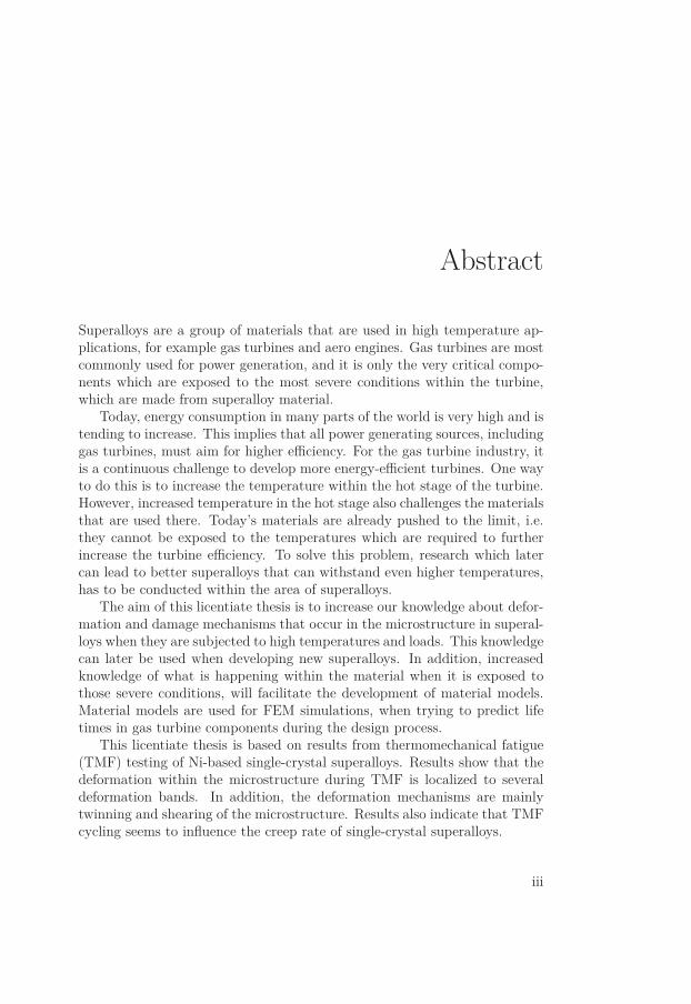
Superalloys are a group of materials that are used in high temperature ap-plications, for example gas turbines and aero engines. Gas turbines are mostcommonly used for power generation, and it is only the very critical compo-nents which are exposed to the most severe conditions within the turbine,which are made from superalloy material.
Today, energy consumption in many parts of the world is very high and istending to increase. This implies that all power generating sources, includinggas turbines, must aim for higher efficiency. For the gas turbine industry, itis a continuous challenge to develop more energy-efficient turbines. One wayto do this is to increase the temperature within the hot stage of the turbine.However, increased temperature in the hot stage also challenges the materialsthat are used there. Today’s materials are already pushed to the limit, i.e.they cannot be exposed to the temperatures which are required to furtherincrease the turbine efficiency. To solve this problem, research which latercan lead to better superalloys that can withstand even higher temperatures,has to be conducted within the area of superalloys.
The aim of this licentiate thesis is to increase our knowledge about defor-mation and damage mechanisms that occur in the microstructure in superal-loys when they are subjected to high temperatures and loads. This knowledgecan later be used when developing new superalloys. In addition, increasedknowledge of what is happening within the material when it is exposed tothose severe conditions, will facilitate the development of material models.Material models are used for FEM simulations, when trying to predict lifetimes in gas turbine components during the design process.
This licentiate thesis is based on results from thermomechanical fatigue(TMF) testing of Ni-based single-crystal superalloys. Results show that thedeformation within the microstructure during TMF is localized to severaldeformation bands. In addition, the deformation mechanisms are mainlytwinning and shearing of the microstructure. Results also indicate that TMFcycling seems to influence the creep rate of single-crystal superalloys.
iii

Acknowledgements
I discovered my interest for research nel cuore verde d’Italia in spring 2009.My master thesis project had brought me to Università di Perugia, and thereI was lucky to be a part of a great research group within material science.Not only did they teach me how to make genuine Italian home made pasta,but they also encouraged me to a future career as a researcher. Hence, thisbook would never have been written without my stay in Umbria.
First I would like to express my very great appreciation to my supervisorJohan Moverare who have guided, supported and encouraged me from dayone as a Ph.D. student. Thank you for believing in me and for teaching mehow dislocations travel in superalloys.
My co-supervisors Kjell Simonsson, Sten Johansson and Daniel Leider-mark are also acknowledged for fruitful discussions during this project. A col-lective acknowledgement goes out to the whole Engineering Materials groupfor creating enjoyable and inspiring days at work. In addition, the IEI tech-nicians and workshop guys are greatly acknowledged for all their help.
The Swedish Energy Agency and Siemens Industrial Turbomachinery inFinspång, Sweden have financed this project through KME for which they areall greatly acknowledged. Also AFM and its graduate school Agora Materiaeare recognised for providing knowledge.
I also want to thank my fellow Ph.D. students at IEI for creating sucha great atmosphere. To have a coffee in Dan’s Corner, a short chat in thecorridor or going to the IEI gym really can brighten days when it is needed.
To conclude I would like to thank my family and friends for always beingthere. Especially my sister Maria who have designed the beautiful cover ofthis thesis. My final and deepest gratitude goes to my beloved Åsa for herlove and support.
Mikael SegersällLinköping, February 2013
v

List of Papers
The following papers have been included in this thesis:
I. M. Segersäll, J. J. Moverare, K. Simonsson, and S. Johansson, ”Defor-mation and damage mechanisms during thermomechanical fatigue ofa single-crystal superalloy in the 〈001〉 and 〈011〉 directions,” in Su-peralloys 2012 (E. S. Huron, R. C. Reed, M. Hardy, M. J. Mills, R.E. Montero, P. D. Portella, and J. Talesman, eds.), pp. 215-223, TheMinerals, Metals and Materials Society, 2012.
II. M. Segersäll and J. J. Moverare, ”Crystallographic orientation influenceon the serrated yielding behavior of a single-crystal superalloy,” Mate-rials, vol. 6, no. 2, pp. 437-444, 2013.
III. M. Segersäll, J. J. Moverare, D. Leidermark, and K. Simonsson, ”Creepand stress relaxation anisotropy of a single-crystal superalloy.”In manuscript.
Contribution to the papers included:
For above papers, I have been the main contributor of the microstructureinvestigations and manuscript writing. In addition, I have conducted theTMF tests in Paper III. However, in paper I and II, Johan Moverare hasperformed the mechanical testing.
Papers not included in this thesis:
IV. D. Leidermark, J. Moverare, M. Segersäll, K. Simonsson, S. Sjöström,and S. Johansson, ”Evaluation of fatigue crack initiation in a notchedsingle-crystal superalloy component,” Procedia Engineering, vol. 10,pp. 619-624, 2011.
vii
V. J. J. Moverare, M. Segersäll, A. Sato, S. Johansson, and R. C. Reed,”Thermomechanical fatigue of single-crystal superalloys: Influence ofcomposition and microstructure,” in Superalloys 2012 (E. S. Huron, R.C. Reed, M. Hardy, M. J. Mills, R. E. Montero, P. D. Portella, andJ. Talesman, eds.), pp. 369-377, The Minerals, Metals and MaterialsSociety, 2012.
VI. M. Segersäll, J. J. Moverare, D. Leidermark, and K. Simonsson, ”Hightemperature stress relaxation of a Ni-based single-crystal superalloy,”Accepted for presentation at the 13th International Conference on Frac-ture, Beijing, China, June 16-21, 2013.
viii
Contents
Abstract iii
Acknowledgements v
List of Papers vii
Contents ix
Abbreviations xi
Part I Background & Theory 1
1 Introduction 31.1 Background of the research project . . . . . . . . . . . . . . . 31.2 Relevance of research . . . . . . . . . . . . . . . . . . . . . . . 31.3 Aims and research questions . . . . . . . . . . . . . . . . . . . 41.4 Structure of the thesis . . . . . . . . . . . . . . . . . . . . . . 5
2 Gas turbines 72.1 General description . . . . . . . . . . . . . . . . . . . . . . . . 72.2 The gas turbine blade . . . . . . . . . . . . . . . . . . . . . . 82.3 Superalloys . . . . . . . . . . . . . . . . . . . . . . . . . . . . 102.4 The gas turbine blade in single-crystal form . . . . . . . . . . 10
3 Ni-based single-crystal superalloys 133.1 Single-crystal vs. poly-crystal superalloys . . . . . . . . . . . . 133.2 Composition and phases . . . . . . . . . . . . . . . . . . . . . 14
3.2.1 The typical γ/γ′-microstructure . . . . . . . . . . . . . 143.2.2 Other phases . . . . . . . . . . . . . . . . . . . . . . . 163.2.3 Alloying elements . . . . . . . . . . . . . . . . . . . . . 17
ix
3.3 Microstructure degradation at high temperatures . . . . . . . 193.4 Some remarkable mechanical properties . . . . . . . . . . . . . 20
3.4.1 Yield strength temperature dependence . . . . . . . . . 213.4.2 Tension/compression asymmetry . . . . . . . . . . . . 23
3.5 The crystal orientation influence on mechanical properties . . 243.5.1 Elasticity . . . . . . . . . . . . . . . . . . . . . . . . . 243.5.2 Yielding behaviour . . . . . . . . . . . . . . . . . . . . 243.5.3 Fatigue and creep . . . . . . . . . . . . . . . . . . . . . 26
4 Ni-based single-crystal superalloys as blade material 294.1 Fatigue . . . . . . . . . . . . . . . . . . . . . . . . . . . . . . . 29
4.1.1 Isothermal fatigue . . . . . . . . . . . . . . . . . . . . . 304.1.2 Thermomechanical fatigue . . . . . . . . . . . . . . . . 30
4.2 Creep . . . . . . . . . . . . . . . . . . . . . . . . . . . . . . . 34
5 Experimental methods 375.1 Material . . . . . . . . . . . . . . . . . . . . . . . . . . . . . . 375.2 Thermomechanical fatigue testing . . . . . . . . . . . . . . . . 385.3 Microstructure investigations . . . . . . . . . . . . . . . . . . . 39
5.3.1 Sample preparation . . . . . . . . . . . . . . . . . . . . 395.3.2 Scanning electron microscopy . . . . . . . . . . . . . . 40
6 Summary of papers included 41
7 Conclusions 45
8 Future work 47
Bibliography 49
Part II Papers Included 57
Paper I: Deformation and damage mechanisms during thermo-mechanical fatigue of a single-crystal superalloy in the 〈001〉and 〈011〉 directions 61
Paper II: Crystallographic orientation influence on the serratedyielding behavior of a single-crystal superalloy 73
Paper III: Creep and stress relaxation anisotropy of a single-crystal superalloy 83
x
Abbreviations
APB Anti Phase BoundaryBCC Body Centered CubicBCT Body Centered TetragonalCRSS Critical Resolved Shear StressDS Directionally SolidifiedDSA Dynamic Strain AgeingEBSD Electron BackScattering DiffractionFCC Face Centered CubicFEM Finite Element MethodIP TMF In-Phase ThermoMechanical FatigueLCF Low Cycle FatigueOP TMF Out-of-Phase ThermoMechanical FatigueRT Room TemperatureSEM Scanning Electron MicroscopySESF Super Extrinsic Stacking FaultTCP Topologically Close PackedTBC Thermal Barrier CoatingTMF ThermoMechanical Fatigue
xi

Part I
Background & Theory

1Introduction
1.1 Background of the research projectThis licentiate thesis is a part of the ongoing research project Fatigue innickel-based single-crystal superalloys under LCF and TMF conditions, whichbegan at Linköping University, Sweden in the fall of 2010. The project in-volves a strong collaboration with Siemens Industrial Turbomachinery AB inFinspång, Sweden and is financed through the Research Consortium of Mate-rials Technology for Thermal Energy Processes (KME), Grant No. KME-502.KME was established in 1997 and consists of seven industrial companies, in-cluding Siemens Industrial Turbomachinery. The research within KME is fi-nanced by both the industries (60%) and the Swedish Energy Agency (40%),and its purpose is to make thermal energy processes more effective.
1.2 Relevance of researchThe project concerns the material group called superalloys. Superalloys showexcellent mechanical and chemical properties at temperatures as high as 1000°C. At these temperatures, other material groups, such as steels, exhibit verypoor properties, which makes superalloys the only alternative in high tem-perature applications. It is mainly two types of industry which use superalloymaterials, the gas turbine and the aero engine industries. Those industriesnot only use the superalloys, but their applications are very much dependenton the superalloy performance. The reason for this dependence is that themost critical components in gas turbines and aero engines are made from su-peralloys, and no other material group can be considered here. In addition,the efficiency of both gas turbines and aero engines is very much dependent
3
PART I. BACKGROUND AND THEORY
on the performance of the superalloys. Since Siemens Industrial Turboma-chinery AB is a collaboration partner in this research project, most methodsare directed towards gas turbine applications rather than aero engines. How-ever, aero engines and gas turbines are very similar constructions, whichmeans that the research in this thesis can be of use to both industries.
Gas turbines are mainly used for power generation. People living in the21st century are consuming more energy than ever, which means that allenergy producing sources including gas turbines must be more efficient. Notonly do we need to produce more energy, the energy produced must also beproduced in an environmental friendly way in order to create a sustainableenvironment. Today, it is most common to use non-renewable fuels, suchas natural gas, when operating a gas turbine. However, it is possible touse biogas as fuel. Gas turbines are also used to compensate for temporarylack of green energy sources, for example when the wind is not blowing orwhen the sun is not shining. The need for more efficient energy sourcescannot be underestimated, and the aim of this thesis is to provide furtherknowledge about superalloys, which in the long term, can lead to a greenerpower generation.
1.3 Aims and research questionsIn KME’s overall goals for the program period 2010-2013 it is stated that:
”The program will contribute to the conversion to a sustainable energy sys-tem by development of more effective energy processes.”
More specific, the KME-502 project has two aims; the first is to improveknowledge regarding the deformation and damage mechanisms that occur insuperalloys during TMF and LCF (low cycle fatigue) conditions. The secondaim is to develop material models than can be used to predict the servicelife of superalloy components in gas turbines. The latter issue has been thefocus for another thesis, [1], and is not considered here. Instead, the overallaim of the work underlying this licentiate thesis is to increase the knowledgeregarding the deformation and damage mechanisms that occur in superalloysduring high temperatures and loads. More specifically, the following researchquestions have been addressed:
How does the crystal orientation influence the TMF life for a Ni-based single-crystal superalloy?
4
CHAPTER 1. INTRODUCTION
Do the different crystal orientations exhibit different deformation mecha-nisms for TMF conditions?
How do long hold times during TMF cycling affect the fatigue life?
1.4 Structure of the thesisThis licentiate thesis is divided into two parts:
• Part I Background & Theory
• Part II Papers Included
In Part I, Background & Theory, the reader is first introduced to theresearch project; the aims and research questions are stated before a moresubstantial section concerning the scientific subject is presented. Here a de-scription of the gas turbine is provided together with information concerningsuperalloys based on previous research. Later, the experimental methods arepresented, followed by a summary of the papers included. Subsequently theconclusions of the thesis are given. Finally, since this thesis constitutes onestep towards a Ph.D. degree, the future work that is to be conducted in thisresearch project is also presented.
Part II, Papers Included, is based on three papers; one conference paper,one journal paper and one paper which is still in manuscript. These describethe main research that has been conducted in the project.
5

2Gas turbines
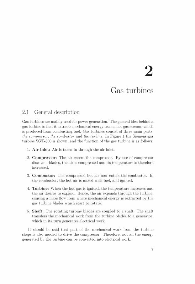
2.1 General descriptionGas turbines are mainly used for power generation. The general idea behind agas turbine is that it extracts mechanical energy from a hot gas stream, whichis produced from combusting fuel. Gas turbines consist of three main parts:the compressor, the combustor and the turbine. In Figure 1 the Siemens gasturbine SGT-800 is shown, and the function of the gas turbine is as follows:
1. Air inlet: Air is taken in through the air inlet.
2. Compressor: The air enters the compressor. By use of compressordiscs and blades, the air is compressed and its temperature is thereforeincreased.
3. Combustor: The compressed hot air now enters the combustor. Inthe combustor, the hot air is mixed with fuel, and ignited.
4. Turbine: When the hot gas is ignited, the temperature increases andthe air desires to expand. Hence, the air expands through the turbine,causing a mass flow from where mechanical energy is extracted by thegas turbine blades which start to rotate.
5. Shaft: The rotating turbine blades are coupled to a shaft. The shafttransfers the mechanical work from the turbine blades to a generator,which in its turn generates electrical work.
It should be said that part of the mechanical work from the turbinestage is also needed to drive the compressor. Therefore, not all the energygenerated by the turbine can be converted into electrical work.
7
PART I. BACKGROUND AND THEORY
1. Air inlet
2. Compressor
5. Shaft 4. Turbine
3. Combustor
Figure 1: An SGT-800 gas turbine, which can produce 50 MW. Courtesy ofSiemens Industrial Turbomachinery AB.
The function of an aero engine is very similar to that of a landbased gasturbine. However, an aero engine works at maximum capacity only duringtake-off and landing, while a landbased gas turbine works at maximum ca-pacity over longer times. Another difference between the two applications issafety. An aero engine has very high safety precautions, and here, failure ofthe most critical components cannot be tolerated since it can have terribleconsequences. However, for a landbased gas turbine, the failure of a criticalcomponent will not have the same terrible consequences. Of course, failurein a landbased gas turbine is not desirable, but is easier to accept. Thismeans that the components in landbased gas turbines can have much longerinspection intervals and service life than aero engine components.
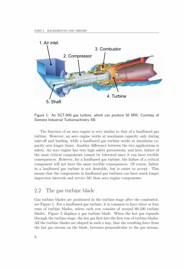
2.2 The gas turbine bladeGas turbine blades are positioned in the turbine stage after the combustor,see Figure 1. For a landbased gas turbine, it is common to have three or fourrows of turbine blades, where each row consists of around 60-100 turbineblades. Figure 2 displays a gas turbine blade. When the hot gas expandsthrough the turbine stage, the hot gas first hits the first row of turbine blades.All the turbine blades are shaped in such a way, that the resulting force fromthe hot gas stream on the blade, becomes perpendicular to the gas stream.
8
CHAPTER 2. GAS TURBINES
Hence, the turbine blades start to rotate. The turbine blades are attached toa disc, which in turn is attached to the shaft. When the blades start to rotate,the disc and shaft also rotate. During service, the turbine blades rotate witha rotational speed of up to 10 000 rpm at temperatures up to 1000 °C.Hence, the gas turbine blades are subjected to significant centrifugal forcesand high temperatures at the same time, which put extreme requirements onthe turbine blade material.
Leading edge
Platform
Trailing edge
Airfoil
2 cm
Figure 2: A Ni-based single-crystal superalloy gas turbine blade. Courtesy ofSiemens Industrial Turbomachinery AB.
As mentioned, there are three or four rows of turbine blades in the tur-bine stage. The first row is subjected to the most severe conditions, sinceit is here the hot gas first enters and has the highest temperature. By thetime the air reaches the second, third and fourth rows of turbine blades, thetemperature has gradually decreased. First stage turbine blades are mostcommonly coated with a thermal barrier coating (TBC) to protect the bladematerial from the high temperature. At the same time, the blade is contin-uously cooled by air from the compressor. The efficiency of the gas turbineis very much dependent on the gas temperature; the higher temperature ofthe gas in the turbine stage the higher efficiency for the turbine. Further,the gas temperature can only be as high as what the first row turbine bladescan withstand. This implies that it is on the performance of the first row ofturbine blades that the whole turbine engine efficiency is determined.
9
PART I. BACKGROUND AND THEORY
2.3 SuperalloysMany components in gas turbines must be made from materials that canwithstand both extreme temperatures and loads. As a materials group su-peralloys are divided into three subgroups: Ni-, Fe- and Co-based superalloys.Common to the superalloys as a group, is that they show good mechanicaland chemical properties at temperatures above 0.6 times the melting tem-perature. Ni-based superalloys which are alloys with nickel as the primaryalloying element are preferred as blade material in the previously discussedapplications, rather than Co- or Fe-based superalloys. What is significant forNi-based superalloys is their high strength, creep and corrosion resistance athigh temperatures [2]. Ni is stable, i.e. has no phase transformations, in itsFCC-structure from room temperature (RT) to its melting temperature at1455 °C.
Superalloys can be used in three different forms: poly-crystal, direction-ally solidified (DS) or single-crystal form. Turbine disc alloys are oftenwrought in poly-crystal form, while it is common to cast blades in DS orsingle-crystal form. DS turbine blades have longitudinal grains, which areoriented parallel to the vertical direction of the blade. On the other hand,single-crystal blades consist of only one grain.
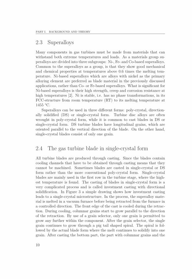
2.4 The gas turbine blade in single-crystal formAll turbine blades are produced through casting. Since the blades containcooling channels that have to be obtained through casting means that theycannot be machined. Sometimes blades are casted in single-crystal or DSform rather than the more conventional poly-crystal form. Single-crystalblades are mainly used in the first row in the turbine stage, where the high-est temperature is found. The casting of blades in single-crystal form is avery complicated process and is called investment casting with directionalsolidification. In Figure 3 a simple drawing shows how investment castingleads to a single-crystal microstructure. In the process, the superalloy mate-rial is melted in a vacuum furnace before being retracted from the furnace ina controlled direction. The front edge of the cast is cooled during the retrac-tion. During cooling, columnar grains start to grow parallel to the directionof the retraction. By use of a grain selector, only one grain is permitted togrow any further within the component. After the grain selector, the singlegrain continues to grow through a pig tail shaped spiral. The spiral is fol-lowed by the actual blade form where the melt continues to solidify into onegrain. After casting the bottom part, the part with columnar grains and the
10
CHAPTER 2. GAS TURBINES
pig tail shaped part, is removed by machining.
Turbine blade
(molten)
Vacuum furnace
Pig tail
Cooling
Direction of retraction
Cooling plate
Water cooling
Cooling
Columnar grains
Solidified metal
Grain selector
Figure 3: Investment casting with directional solidification of a turbine blade insingle-crystal form.
11

3Ni-based single-crystal superalloys
3.1 Single-crystal vs. poly-crystal superalloys
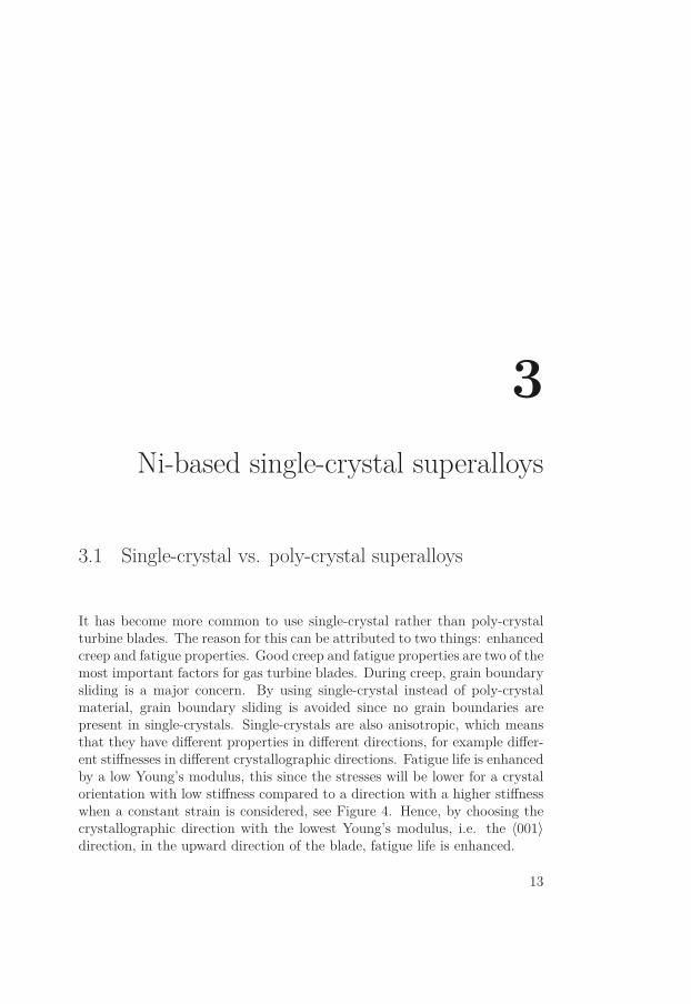
It has become more common to use single-crystal rather than poly-crystalturbine blades. The reason for this can be attributed to two things: enhancedcreep and fatigue properties. Good creep and fatigue properties are two of themost important factors for gas turbine blades. During creep, grain boundarysliding is a major concern. By using single-crystal instead of poly-crystalmaterial, grain boundary sliding is avoided since no grain boundaries arepresent in single-crystals. Single-crystals are also anisotropic, which meansthat they have different properties in different directions, for example differ-ent stiffnesses in different crystallographic directions. Fatigue life is enhancedby a low Young’s modulus, this since the stresses will be lower for a crystalorientation with low stiffness compared to a direction with a higher stiffnesswhen a constant strain is considered, see Figure 4. Hence, by choosing thecrystallographic direction with the lowest Young’s modulus, i.e. the 〈001〉direction, in the upward direction of the blade, fatigue life is enhanced.
13
PART I. BACKGROUND AND THEORY
Strain, ε
Stress, σ
εconstant
σ⟨111⟩
σ⟨011⟩
σ⟨001⟩
⟨111⟩
⟨011⟩
⟨001⟩
Figure 4: Different crystal orientations show different stiffnesses which affect thefatigue lives when a constant strain is considered.
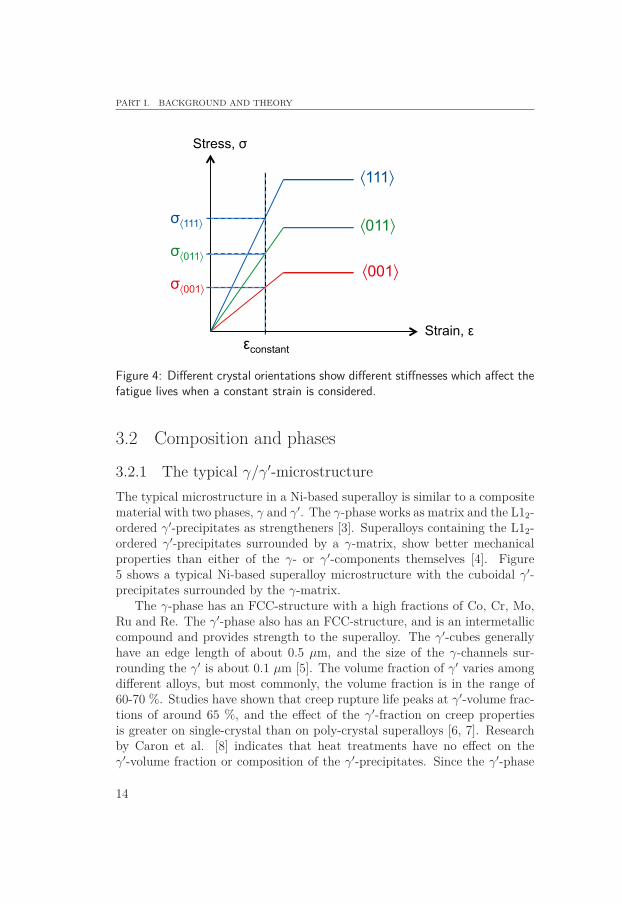
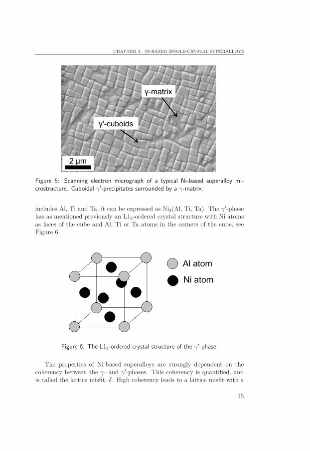
3.2 Composition and phases3.2.1 The typical γ/γ′-microstructureThe typical microstructure in a Ni-based superalloy is similar to a compositematerial with two phases, γ and γ′. The γ-phase works as matrix and the L12-ordered γ′-precipitates as strengtheners [3]. Superalloys containing the L12-ordered γ′-precipitates surrounded by a γ-matrix, show better mechanicalproperties than either of the γ- or γ′-components themselves [4]. Figure5 shows a typical Ni-based superalloy microstructure with the cuboidal γ′-precipitates surrounded by the γ-matrix.
The γ-phase has an FCC-structure with a high fractions of Co, Cr, Mo,Ru and Re. The γ′-phase also has an FCC-structure, and is an intermetalliccompound and provides strength to the superalloy. The γ′-cubes generallyhave an edge length of about 0.5 μm, and the size of the γ-channels sur-rounding the γ′ is about 0.1 μm [5]. The volume fraction of γ′ varies amongdifferent alloys, but most commonly, the volume fraction is in the range of60-70 %. Studies have shown that creep rupture life peaks at γ′-volume frac-tions of around 65 %, and the effect of the γ′-fraction on creep propertiesis greater on single-crystal than on poly-crystal superalloys [6, 7]. Researchby Caron et al. [8] indicates that heat treatments have no effect on theγ′-volume fraction or composition of the γ′-precipitates. Since the γ′-phase
14
CHAPTER 3. NI-BASED SINGLE-CRYSTAL SUPERALLOYS
γ-matrix
γ'-cuboids
2 μm
Figure 5: Scanning electron micrograph of a typical Ni-based superalloy mi-crostructure. Cuboidal γ′-precipitates surrounded by a γ-matrix.
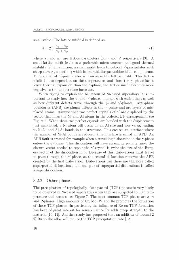
includes Al, Ti and Ta, it can be expressed as Ni3(Al, Ti, Ta). The γ′-phasehas as mentioned previously an L12-ordered crystal structure with Ni atomsas faces of the cube and Al, Ti or Ta atoms in the corners of the cube, seeFigure 6.
Al atom
Ni atom
Figure 6: The L12-ordered crystal structure of the γ′-phase.
The properties of Ni-based superalloys are strongly dependent on thecoherency between the γ- and γ′-phases. This coherency is quantified, andis called the lattice misfit, δ. High coherency leads to a lattice misfit with a
15
PART I. BACKGROUND AND THEORY
small value. The lattice misfit δ is defined as
δ = 2 × aγ − aγ′
aγ + aγ′(1)
where aγ and aγ′ are lattice parameters for γ and γ′ respectively [3]. Asmall lattice misfit leads to a preferable microstructure and good thermalstability [9]. In addition, a small misfit leads to cubical γ′-precipitates withsharp corners, something which is desirable for gas turbine blade components.More spherical γ′-precipitates will increase the lattice misfit. This latticemisfit is also dependent on the temperature, and since the γ′-phase has alower thermal expansion than the γ-phase, the lattice misfit becomes morenegative as the temperature increases.
When trying to explain the behaviour of Ni-based superalloys it is im-portant to study how the γ- and γ′-phases interact with each other, as wellas how different defects travel through the γ- and γ′-phases. Anti-phaseboundaries (APB) are planar defects in the γ′-phase and are layers of mis-placed atoms. Assume that two perfect crystals of γ′ are displaced by thevector that links the Ni and Al atoms in the ordered L12-arrangement, seeFigure 6. When these two perfect crystals are bonded with the displacementjust mentioned, a Ni atom will occur on an Al site and vice versa, leadingto Ni-Ni and Al-Al bonds in the structure. This creates an interface wherethe number of Ni-Al bonds is reduced; this interface is called an APB. AnAPB fault is created for example when a travelling dislocation in the γ-phaseenters the γ′-phase. This dislocation will have an energy penalty, since theclosure vector needed to repair the γ′-crystal is twice the size of the Burg-ers vector of the dislocation in γ. Because of this, dislocations must travelin pairs through the γ′-phase, as the second dislocation removes the APBcreated by the first dislocation. Dislocations like these are therefore calledsuperpartial dislocations, and one pair of superpartial dislocations is calleda superdislocation.
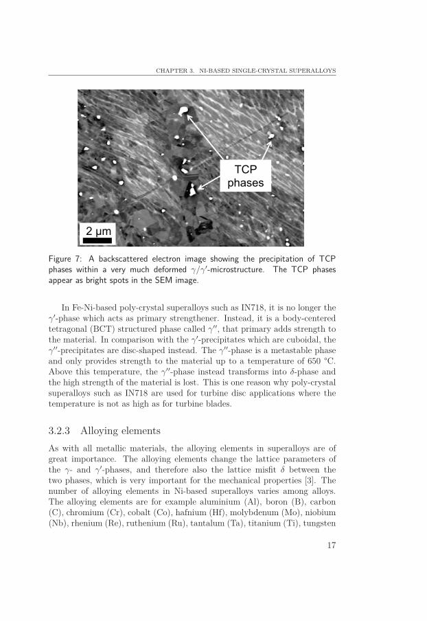
3.2.2 Other phasesThe precipitation of topologically close-packed (TCP) phases is very likelyto be observed in Ni-based superalloys when they are subjected to high tem-perature and stresses, see Figure 7. The most common TCP phases are σ, μand P-phases. High amounts of Cr, Mo, W and Re promotes the formationof these TCP phases. In particular, the influence of Re on TCP formationhas been of great interest for research since Re adds creep strength to thematerial [10, 11]. Another study has proposed that an addition of around 2% Ru to the alloy will reduce the TCP precipitation rate [12].
16
CHAPTER 3. NI-BASED SINGLE-CRYSTAL SUPERALLOYS
2 μm
TCP phases
Figure 7: A backscattered electron image showing the precipitation of TCPphases within a very much deformed γ/γ′-microstructure. The TCP phasesappear as bright spots in the SEM image.
In Fe-Ni-based poly-crystal superalloys such as IN718, it is no longer theγ′-phase which acts as primary strengthener. Instead, it is a body-centeredtetragonal (BCT) structured phase called γ′′, that primary adds strength tothe material. In comparison with the γ′-precipitates which are cuboidal, theγ′′-precipitates are disc-shaped instead. The γ′′-phase is a metastable phaseand only provides strength to the material up to a temperature of 650 °C.Above this temperature, the γ′′-phase instead transforms into δ-phase andthe high strength of the material is lost. This is one reason why poly-crystalsuperalloys such as IN718 are used for turbine disc applications where thetemperature is not as high as for turbine blades.
3.2.3 Alloying elementsAs with all metallic materials, the alloying elements in superalloys are ofgreat importance. The alloying elements change the lattice parameters ofthe γ- and γ′-phases, and therefore also the lattice misfit δ between thetwo phases, which is very important for the mechanical properties [3]. Thenumber of alloying elements in Ni-based superalloys varies among alloys.The alloying elements are for example aluminium (Al), boron (B), carbon(C), chromium (Cr), cobalt (Co), hafnium (Hf), molybdenum (Mo), niobium(Nb), rhenium (Re), ruthenium (Ru), tantalum (Ta), titanium (Ti), tungsten
17
PART I. BACKGROUND AND THEORY
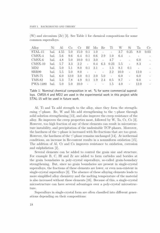
(W) and zirconium (Zr) [3]. See Table 1 for chemical compositions for somecommon superalloys.
Alloy Ni Al Co Cr Hf Mo Re Ti W Si Ta CeSTAL-15 bal. 4.55 5.0 15.0 0.1 1.0 - - 3.7 0.25 8.0 0.03CMSX-4 bal. 5.6 9.6 6.4 0.1 0.6 2.9 1.0 6.4 - - -CMSX-6 bal. 4.8 5.0 10.0 0.1 3.0 - 4.7 - - 6.0 -CMSX-10 bal. 5.7 3.3 2.2 - 0.4 6.3 0.23 5.5 - 8.3 -MD2 bal. 5.0 5.1 8.0 0.1 2.1 - 1.3 8.1 0.1 - -SRR99 bal. 5.5 5.0 8.0 - - - 2.2 10.0 - 12.0 -TMS-75 bal. 6.0 12.0 3.0 0.1 2.0 5.0 - 6.0 - 6.0 -TMS-82 bal. 5.3 7.8 4.9 0.1 1.9 2.4 0.5 8.7 - 6.0 -PWA-1480 bal. 5.0 5.0 10.0 - - - 1.5 4.0 - 12.0 -
Table 1: Nominal chemical composition in wt. % for some commercial superal-loys. CMSX-4 and MD2 are used in the experimental work in this project whileSTAL-15 will be used in future work.
Al, Ti and Ta add strength to the alloy, since they form the strength-ening γ′-phase. Re, W and Mo add strengthening to the γ-phase throughsolid solution strengthening [13], and also improve the creep resistance of thealloy. Re improves the creep properties most, followed by W, Ta, Cr, Co [3].However, too high fraction of any of these elements can result in microstruc-ture instability, and precipitation of the undesirable TCP-phases. Moreover,the hardness of the γ-phase is increased with Re-fractions that are too great.However, the hardness of the γ′-phase remains unchanged [14]. At isothermalconditions, an increase in Re-content results in a nonuniform oxidation [15].The addition of Al, Cr and Co improves resistance to oxidation, corrosionand sulphidation [2].
Several elements can be added to control the grain size and structure.For example B, C, Hf and Zr are added to form carbides and borides atthe grain boundaries in poly-crystal superalloys, so-called grain-boundarystrengthening. But, since no grain boundaries are present in single-crystalsuperalloys, the fractions of these elements are lower, or even non-existent insingle-crystal superalloys [3]. The absence of these alloying elements leads tomore simplified alloy chemistry and the melting temperature of the materialis also increased without these elements [16]. Because of this, a single-crystalmicrostructure can have several advantages over a poly-crystal microstruc-ture.
Superalloys in single-crystal form are often classified into different gener-ations depending on their compositions:
18
CHAPTER 3. NI-BASED SINGLE-CRYSTAL SUPERALLOYS
• 1st generation: no Re or Ru.
• 2nd generation: approximately 3 % Re and no Ru.
• 3rd generation: approximately 6 % Re and no Ru.
• 4th generation: contains both Re and Ru.
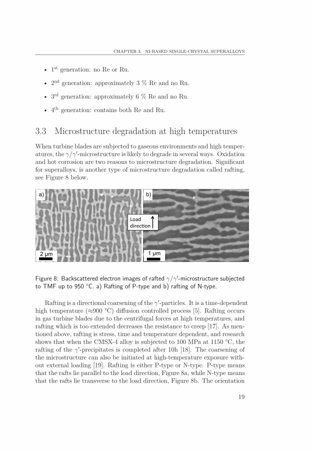
3.3 Microstructure degradation at high temperaturesWhen turbine blades are subjected to gaseous environments and high temper-atures, the γ/γ′-microstructure is likely to degrade in several ways. Oxidationand hot corrosion are two reasons to microstructure degradation. Significantfor superalloys, is another type of microstructure degradation called rafting,see Figure 8 below.
1 μm 2 μm
a) b)
Figure 8: Backscattered electron images of rafted γ/γ′-microstructure subjectedto TMF up to 950 °C. a) Rafting of P-type and b) rafting of N-type.
Rafting is a directional coarsening of the γ′-particles. It is a time-dependenthigh temperature (≈900 °C) diffusion controlled process [5]. Rafting occursin gas turbine blades due to the centrifugal forces at high temperatures, andrafting which is too extended decreases the resistance to creep [17]. As men-tioned above, rafting is stress, time and temperature dependent, and researchshows that when the CMSX-4 alloy is subjected to 100 MPa at 1150 °C, therafting of the γ′-precipitates is completed after 10h [18]. The coarsening ofthe microstructure can also be initiated at high-temperature exposure with-out external loading [19]. Rafting is either P-type or N-type. P-type meansthat the rafts lie parallel to the load direction, Figure 8a, while N-type meansthat the rafts lie transverse to the load direction, Figure 8b. The orientation
19
PART I. BACKGROUND AND THEORY
of the rafting is dependent on the lattice misfit [3]. A negative misfit, whichfor example is observed in the alloy CMSX-4, leads to an N-type rafting ifthe loading is tensile, and P-type for compressive loadings. If instead thealloys has a positive lattice misfit, tensile stresses lead to a P-type rafting,while compressive stresses lead to rafting of the N-type.
Rafting of the γ/γ′-microstructure starts when superalloys are subjectedto loadings at homologous temperatures up to 0.8. By homologous temper-ature one means the ratio between the operating temperature and meltingtemperature of the material. At this temperature the microstructure startsto degrade, which results in a coarsened microstructure [20]. If the raftingbecomes too large, instead of the γ-phase being the matrix as is usually thecase, the γ′-phase can be considered as a continuous matrix [3].
A rafting parameter R has been proposed by Ignat et al. [21]. The raftingparameter R is equal to
R = 2L2
4LT= L
2T(2)
where L and T are the average mean linear lengths of the γ′-precipitates indirections normal and parallel to the loading direction. When no rafting isobserved, i.e. when the γ′-precipitates still have a cubic form, L and T areboth 1 and the rafting parameter is therefore 0.5. An increase in raftingtherefore leads to an increased rafting parameter R. Researchers have in-vestigated how rafting through long-term ageing and pre-deformation, affectthe mechanical behaviour of a single-crystal superalloy [19]. Specimens withdifferent crystallographic orientations were pre-deformed, either in tension orcompression, and long-term aged prior mechanical testing. The specimenswhich obtained a rafted microstructure, showed a decrease of 25% in yieldstrength, while specimens with less rafting showed a smaller decrease in yieldstrength.
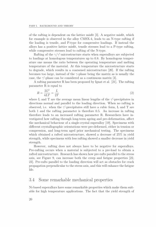
However, rafting does not always have to be negative for superalloys.Pre-rafting occurs when a material is subjected to a pre-load to obtain arafted microstructure. Research has shown how pre-rafts parallel to the stressaxis, see Figure 9, can increase both the creep and fatigue properties [22,23]. Pre-rafts parallel to the loading direction will act as obstacles for crackpropagation perpendicular to the stress axis, and this will enhance the fatiguelife.
3.4 Some remarkable mechanical propertiesNi-based superalloys have some remarkable properties which make them suit-able for high temperature applications. The fact that the yield strength of
20
CHAPTER 3. NI-BASED SINGLE-CRYSTAL SUPERALLOYS
σ
σ
Figure 9: Rafting of the γ/γ′-microstructure parallel to the load direction canincrease both fatigue and creep properties [22, 23].
superalloys increases with increased temperature is particular and togetherwith the good fatigue and creep properties makes them a good choice forturbine blade material.
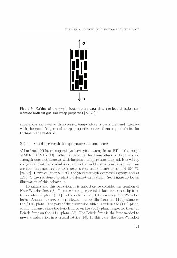
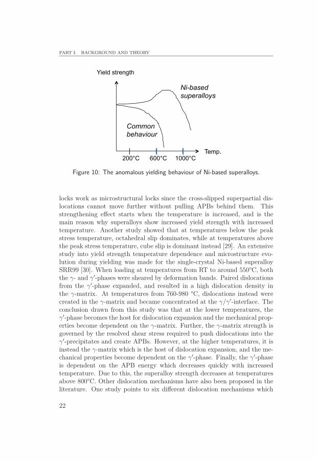
3.4.1 Yield strength temperature dependenceγ′-hardened Ni-based superalloys have yield strengths at RT in the rangeof 900-1300 MPa [13]. What is particular for these alloys is that the yieldstrength does not decrease with increased temperature. Instead, it is widelyrecognized that for several superalloys the yield stress is increased with in-creased temperatures up to a peak stress temperature of around 800 °C[24–27]. However, after 800 °C, the yield strength decreases rapidly, and at1200 °C the resistance to plastic deformation is small. See Figure 10 for anillustration of this behaviour.
To understand this behaviour it is important to consider the creation ofKear-Wilsdorf locks [3]. This is when superpartial dislocations cross-slip fromthe octahedral plane {111} to the cube plane {001}, creating Kear-Wilsdorflocks. Assume a screw superdislocation cross-slip from the {111} plane tothe {001} plane. The part of the dislocation which is still in the {111} plane,cannot advance since the Peierls force on the {001} plane is greater than thePeierls force on the {111} plane [28]. The Peierls force is the force needed tomove a dislocation in a crystal lattice [16]. In this case, the Kear-Wilsdorf
21
PART I. BACKGROUND AND THEORY
Temp.
Yield strength
1000°C 600°C 200°C
Ni-based superalloys
Common behaviour
Figure 10: The anomalous yielding behaviour of Ni-based superalloys.
locks work as microstructural locks since the cross-slipped superpartial dis-locations cannot move further without pulling APBs behind them. Thisstrengthening effect starts when the temperature is increased, and is themain reason why superalloys show increased yield strength with increasedtemperature. Another study showed that at temperatures below the peakstress temperature, octahedral slip dominates, while at temperatures abovethe peak stress temperature, cube slip is dominant instead [29]. An extensivestudy into yield strength temperature dependence and microstructure evo-lution during yielding was made for the single-crystal Ni-based superalloySRR99 [30]. When loading at temperatures from RT to around 550°C, boththe γ- and γ′-phases were sheared by deformation bands. Paired dislocationsfrom the γ′-phase expanded, and resulted in a high dislocation density inthe γ-matrix. At temperatures from 760-980 °C, dislocations instead werecreated in the γ-matrix and became concentrated at the γ/γ′-interface. Theconclusion drawn from this study was that at the lower temperatures, theγ′-phase becomes the host for dislocation expansion and the mechanical prop-erties become dependent on the γ-matrix. Further, the γ-matrix strength isgoverned by the resolved shear stress required to push dislocations into theγ′-precipitates and create APBs. However, at the higher temperatures, it isinstead the γ-matrix which is the host of dislocation expansion, and the me-chanical properties become dependent on the γ′-phase. Finally, the γ′-phaseis dependent on the APB energy which decreases quickly with increasedtemperature. Due to this, the superalloy strength decreases at temperaturesabove 800°C. Other dislocation mechanisms have also been proposed in theliterature. One study points to six different dislocation mechanisms which
22
CHAPTER 3. NI-BASED SINGLE-CRYSTAL SUPERALLOYS
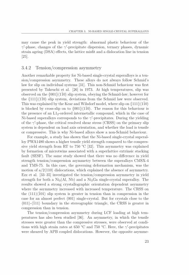
may cause the peak in yield strength: abnormal plastic behaviour of theγ′-phase, changes of the γ′-precipitate dispersion, ternary phases, dynamicstrain ageing (DSA) effects, the lattice misfit and a dislocation line in tension[25].
3.4.2 Tension/compression asymmetryAnother remarkable property for Ni-based single-crystal superalloys is a ten-sion/compression asymmetry. These alloys do not always follow Schmid’slaw for slip on individual systems [31]. This non-Schmid behaviour was firstpresented by Takeuchi et al. [26] in 1973. At high temperatures, slip wasobserved on the {001}〈11̄0〉 slip system, obeying the Schmid-law; however forthe {111}〈11̄0〉 slip system, deviations from the Schmid law were observed.This was explained by the Kear and Wilsdorf model, where slip on {111}〈11̄0〉is blocked by cross-slip on to {001}〈11̄0〉. The reason for this behaviour isthe presence of an L12-ordered intermetallic compound, which in the case ofNi-based superalloys corresponds to the γ′-precipitates. During the yieldingof the γ′-phase, the critical resolved shear stress (CRSS) on the primary slipsystem is dependent on load axis orientation, and whether the load is tensileor compressive. This is why Ni-based alloys show a non-Schmid behaviour.
For example, a study has shown that the Ni-based single-crystal superal-loy PWA1480 shows a higher tensile yield strength compared to the compres-sive yield strength from RT to 750 °C [32]. This asymmetry was explainedby formation of microtwins associated with a superlattice extrinsic stackingfault (SESF). The same study showed that there was no difference in yieldstrength tension/compression asymmetry between the superalloys CMSX-4and TMS-75. In this case, the governing deformation mechanism, was themotion of a/2〈110〉 dislocations, which explained the absence of asymmetry.Ezz et al. [33–35] investigated the tension/compression asymmetry in yieldstrength for both a Ni3(Al, Nb) and a Ni3Ga single-crystal superalloy. Theresults showed a strong crystallographic orientation dependent asymmetrywhere the asymmetry increased with increased temperature. The CRSS onthe (111)〈1̄01〉 slip system is greater in tension than in compression in thecase for an almost perfect 〈001〉 single-crystal. But for crystals close to the〈011〉-〈1̄11〉 boundary in the stereographic triangle, the CRSS is greater incompression than in tension.
The tension/compression asymmetry during LCF loading at high tem-peratures has also been studied [36]. An asymmetry, in which the tensilestresses were greater than the compressive stresses, were observed at condi-tions with high strain rates at 650 °C and 750 °C. Here, the γ′-precipitateswere sheared by APB coupled dislocations. However, the opposite asymme-
23
PART I. BACKGROUND AND THEORY
try, where compressive stresses greater than tensile stresses, was observedat low strain rates at 750 °C and at high strain rates at 850 °C. Here theasymmetry was associated with SESF in the γ′-precipitates. At 950 °C notension/compression asymmetry was found during LCF.
The chemical composition of the superalloy can also influence the asym-metry. A high amount of Ta resulted in higher tensile yield strength com-pared to compressive yield strength at temperatures from 720-750 °C [37].The asymmetry was explained by microtwin formation due to slip at the{111}〈112〉 system. This study also investigated the tension/compressionasymmetry in creep strength, but in this case, no asymmetry was found forthe superalloy with a high Ta fraction.
3.5 The crystal orientation influence on mechanical prop-erties
3.5.1 ElasticityNi-based single-crystal superalloys are highly anisotropic materials, whichmeans that have different properties in different crystallographic directions.In single-crystal form, Ni is elastically anisotropic, i.e. it displays differentelastic properties in different directions. The change in Young’s modulus indifferent crystal directions will influence how the dislocations cross-slip be-tween the planes. Poly-crystal alloys do not have this anisotropic behaviourin stiffness, since the large number of grains, which all have different crystal-lographic orientation, lead to a more isotropic material. The stiffness for apoly-crystal material is the average value of all grain orientation stiffnesses.Pure Ni in poly-crystal form, has a stiffness E = 207 GPa, compared to Ni insingle-crystal form which has E〈001〉 = 125 GPa, E〈011〉 = 220 GPa and E〈111〉= 294 GPa. Those values are for pure Ni, but Ni-based superalloys demon-strate similar stiffnesses. Elastic anisotropy due to the rafting phenomenoncan also occur, and this anisotropy is increased with increased temperature.For example, studies show that the elastic anisotropy factor E[100]/E[001] in-creases up to 1.010-1.025 at temperatures of 1000 °C [38]. Research alsoshows that the stiffness strongly decreases with increased temperature [39].
3.5.2 Yielding behaviourThe orientation dependence of the tension/compression asymmetry of single-crystal superalloys is widely recognized. Materials close to 〈001〉 in the stere-ographic triangle are stronger in tension than compression while materials
24
CHAPTER 3. NI-BASED SINGLE-CRYSTAL SUPERALLOYS
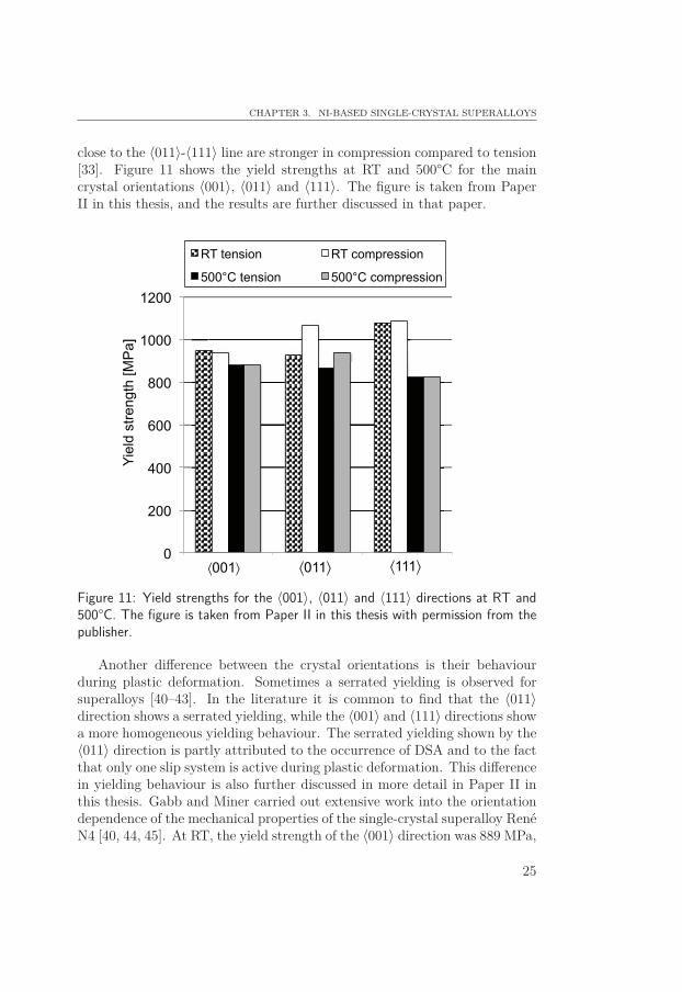
close to the 〈011〉-〈111〉 line are stronger in compression compared to tension[33]. Figure 11 shows the yield strengths at RT and 500°C for the maincrystal orientations 〈001〉, 〈011〉 and 〈111〉. The figure is taken from PaperII in this thesis, and the results are further discussed in that paper.
0
200
400
600
800
1000
1200
Yiel
d st
reng
th [M
Pa]
RT tension RT compression
500°C tension 500°C compression
⟨001⟩ ⟨011⟩ ⟨111⟩
Figure 11: Yield strengths for the 〈001〉, 〈011〉 and 〈111〉 directions at RT and500°C. The figure is taken from Paper II in this thesis with permission from thepublisher.
Another difference between the crystal orientations is their behaviourduring plastic deformation. Sometimes a serrated yielding is observed forsuperalloys [40–43]. In the literature it is common to find that the 〈011〉direction shows a serrated yielding, while the 〈001〉 and 〈111〉 directions showa more homogeneous yielding behaviour. The serrated yielding shown by the〈011〉 direction is partly attributed to the occurrence of DSA and to the factthat only one slip system is active during plastic deformation. This differencein yielding behaviour is also further discussed in more detail in Paper II inthis thesis. Gabb and Miner carried out extensive work into the orientationdependence of the mechanical properties of the single-crystal superalloy RenéN4 [40, 44, 45]. At RT, the yield strength of the 〈001〉 direction was 889 MPa,
25
PART I. BACKGROUND AND THEORY
while it was 830 MPa for the 〈011〉 direction. When the temperature wasincreased to 760 °C, the yield strength increased for the 〈001〉 direction, butdecreased for the 〈011〉 direction. At an even higher temperature, 980 °C,there was a clear decrease in yield strength for both directions. At yielding,the 〈011〉 direction showed a serrated yielding behaviour and in addition, loudpops were heard during deformation. The serration of the 〈011〉 directionwas explained by the fact that only one single slip system was active forthis direction. A tension/compression asymmetry in yield strength was alsoobserved. Here the 〈001〉 direction was stronger in tension than compression.Orientations near 〈011〉 in the stereographic triangle displayed the oppositebehaviour and in such cases the yield strength was higher in compressionthan tension. Fatigue lives were found to be highly orientation dependentand orientations with low stiffness showed longer fatigue lives.
The hearing of loud pops during the yielding of 〈011〉 loaded materialreported by Gabb and Miner is interesting. Similar sounds were observedwhen coated CMSX-4 material was tested, and acoustic emission was usedto measure the noise [46]. The 〈011〉 direction generated a sound while the〈001〉 and 〈111〉 directions were more quieter. Paper III in this thesis showsthe same result. Here a clear sound was heard from the 〈011〉 direction duringloading into a TMF cycle.
Another study has also reported a different yielding behaviour for the〈011〉 direction [47]. In this case, a 〈011〉 oriented single-crystal superalloyshowed both an upper and a lower yield point and a propagation of Lüdersbands, while the yield point for 〈001〉 and 〈111〉 was clearly marked. Defor-mation bands were visible on the surfaces of the specimens, and the path ofthe bands depended on the loading direction.
3.5.3 Fatigue and creepAs mentioned, single-crystal materials are highly anisotropic. Since goodfatigue resistance is enhanced by a low stiffness and different orientations ex-hibit different stiffnesses, fatigue life is highly crystal orientation dependent.The 〈001〉 crystallographic direction has the lowest stiffness and is thereforepreferred as upward direction for gas turbine blade applications.
Research into creep properties in different crystallographic directions showsthat creep performance of superalloys is strongly crystal orientation depen-dent. Literature studies often conclude that the 〈011〉 direction has worsecreep properties compared to the 〈001〉 and 〈111〉 directions [48–51]. Oneexplanation for this is the orientation of the rafted γ′-particles [48]. In 〈011〉oriented specimens, the orientation of the rafting is 45◦ from the stress axiswhile for 〈001〉 oriented specimens the rafting is either parallel or perpen-
26

CHAPTER 3. NI-BASED SINGLE-CRYSTAL SUPERALLOYS
dicular to the stress axis. The γ′-rafts oriented 45◦ from the stress axis donot act as good obstacles for dislocation motion as the parallel or perpen-dicular γ′-rafts, wherefore the 〈011〉 direction shows less creep strength thanthe 〈001〉 direction. Other researchers state that the tensile creep propertiesdecrease in the sequence 〈111〉, 〈001〉, 〈011〉 while in compression the creepproperties decreases in the sequence 〈001〉, 〈111〉, 〈011〉 [49]. Kakehi showedthat the 〈001〉 direction has better creep properties compared to the 〈011〉direction [50, 51]. In the same study, it was found that the 〈001〉 directionshows better properties in tension than compression during creep at 700°Cwhile the 〈011〉 direction was stronger in compression than in tension. Thus,an inverted tension/compression asymmetry was found for the 〈001〉 and〈011〉 directions. The tension/compression asymmetry in creep strength wasalso studied by Tsuno et al. for the 〈001〉 direction [32]. The asymmetry wasattributed to twin formation during compression creep. Mechanical twinsweaken the material and therefore 〈001〉 has better creep strength in tensioncompared to compression. They also concluded that the creep asymmetryincreases with increased temperature from 750 to 900 °C.
27

4Ni-based single-crystal superalloys as
blade material
There are two main reasons for choosing single-crystal instead of poly-crystalNi-based superalloys as blade material in gas turbines; namely, the favourablefatigue and creep properties shown by single-crystal material. Single-crystalsare anisotropic, meaning they have different properties in different directions.Fatigue properties are favoured by a low Young’s modulus, and by choosingthe direction with the lowest stiffness in the upward direction in the turbineblade, fatigue properties of the airfoils are enhanced. This is why turbineblades always are casted with the 〈001〉 crystal orientation upward, boththe 〈011〉 and 〈111〉 directions have higher stiffnesses and are therefore notpreferred. However, the secondary crystal orientation is not controlled duringcasting of the turbine blades. During service, the turbine blades are alsosubjected to constant loads at high temperatures. Since the distance betweenthe blade tip and engine housing is very narrow, it is highly important thatthe deformation over time is not too extensive. Time-dependent inelasticdeformation is referred to as creep deformation, and good resistance to creepis of great importance for gas turbine blades. During creep deformation,grain boundary sliding is a problem. By using single-crystal instead of poly-crystal material, grain boundary sliding is avoided since there are no grainboundaries in single-crystal materials.
4.1 FatigueDepending on which part of the turbine blade that is considered, fatiguedamage is attributed to different types of mechanisms. Most parts of the
29
PART I. BACKGROUND AND THEORY
blade exhibit temperature variations. However, as long as the maximumtemperature does not exceed intermediate temperatures, approximately 500°C, these variations will not affect the fatigue life that much. For example,the blade foot is rarely subjected to temperatures above 500 °C, whereforeisothermal fatigue testing, for example LCF, is enough when trying to simu-late those conditions. But, at other parts of the blade where the temperaturesare higher, fatigue life is very much dependent on the temperature variations.Here TMF testing must be considered to fully understand the fatigue damagethat occurs in the microstructure.
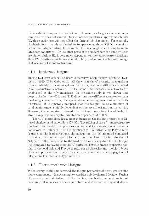
4.1.1 Isothermal fatigueDuring LCF over 850 °C, Ni-based superalloys often display softening. LCFtests at 1050 °C by Gabb et al. [52] show that the γ′-precipitates transformfrom a cuboidal to a more spherodized form, and in addition a coarsenedγ′-microstructure is obtained. At the same time, dislocation networks areestablished at the γ/γ′-interfaces. In the same study it was shown thatdespite the fact the 〈001〉 and 〈111〉 directions have different monotonic strainhardening characteristics, the cyclic stress softening was similar for bothdirections. It is generally accepted that the fatigue life as a function oftotal strain range, is highly dependent on the crystal orientation tested [44].However, the same study showed that fatigue life as function of inelasticstrain range was not crystal orientation dependent at 760 °C.
The γ/γ′-morphology has a great influence on the fatigue properties of Ni-based single-crystal superalloys [53–55]. The rafting of the γ/γ′-microstructurehas been discussed in the previous chapter and the orientation of the raftshas shown to influence LCF life significantly. By introducing P-type rafts(parallel to the load direction), the fatigue life can be enhanced comparedto that with cuboidal γ′-particles. On the other hand, the introduction ofN-type of rafts (transverse to the load direction) is negative for the fatiguelife, compared to having cuboidal γ′-particles. Fatigue cracks propagate nor-mal to the load axis and P-type of rafts act as obstacles and therefore blockthe crack propagation. Hence, N-type rafts do not stop the propagation offatigue crack as well as P-type rafts do.
4.1.2 Thermomechanical fatigueWhen trying to fully understand the fatigue properties of a real gas turbineblade component, it is not enough to consider only isothermal fatigue. Duringthe start-up and shut-down of the turbine, the blade temperature is notconstant, but increases as the engine starts and decreases during shut-down.
30
CHAPTER 4. NI-BASED SINGLE-CRYSTAL SUPERALLOYS AS BLADE MATERIAL
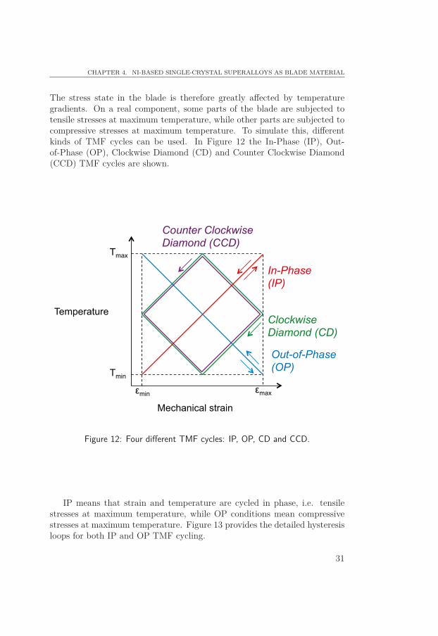
The stress state in the blade is therefore greatly affected by temperaturegradients. On a real component, some parts of the blade are subjected totensile stresses at maximum temperature, while other parts are subjected tocompressive stresses at maximum temperature. To simulate this, differentkinds of TMF cycles can be used. In Figure 12 the In-Phase (IP), Out-of-Phase (OP), Clockwise Diamond (CD) and Counter Clockwise Diamond(CCD) TMF cycles are shown.
Mechanical strain
Temperature
Tmax
Tmin
εmin εmax
In-Phase (IP)
Out-of-Phase (OP)
Clockwise Diamond (CD)
Counter Clockwise Diamond (CCD)
Figure 12: Four different TMF cycles: IP, OP, CD and CCD.
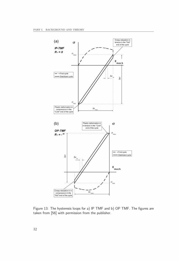
IP means that strain and temperature are cycled in phase, i.e. tensilestresses at maximum temperature, while OP conditions mean compressivestresses at maximum temperature. Figure 13 provides the detailed hysteresisloops for both IP and OP TMF cycling.
31
PART I. BACKGROUND AND THEORY
Figure 13: The hysteresis loops for a) IP TMF and b) OP TMF. The figures aretaken from [56] with permission from the publisher.
32
CHAPTER 4. NI-BASED SINGLE-CRYSTAL SUPERALLOYS AS BLADE MATERIAL
During IP TMF, high temperature creep relaxation in tension and lowtemperature plastic deformation in compression will occur, which is typicalfor a cold-spot on the turbine blade. On the other hand, during OP TMF,high temperature creep relaxation in compression and low temperature plas-tic deformation in tension will occur which is typical for a hot-spot on theblade. It is common to perform OP TMF testing, since TMF damage in gasturbine blades is often localized to these hot-spots, at least for the hottestpart of a turbine blade. Due to thermal expansion, those hot-spots desireto expand, however, the hot-spots cannot expand independently since theexpansion of the hot-spot is prevented by its cooler surrounding. This meansthat the hot-spots will be in compression. This is why OP TMF testing ismore component near than IP TMF testing. If IP and OP cycles simulatescold- and hot-spots on the blade respectively, the CD and CCD cycles on theother hand, simulates transient effects due to different heating and coolingrates of thin and thick sections in a blade that occur during start-up andshut-down of a turbine engine.
The differences between IP and OP TMF were studied by Han et al. [57]and IP TMF life was found to be longer than OP TMF life. During IP TMF,creep deformation was dominant while oxidation caused the shorter life timeduring OP TMF. The same study also discussed the influence of mean stresson TMF life. IP TMF cycling leads to compressive mean stresses while OPTMF cycling instead leads to tensile mean stresses. Since compressive meanstresses hinder crack nucleation while tensile mean stresses promotes cracknucleation, IP cycling leads to better fatigue lives compared to OP TMFcycling. Also Liu et al. studied the differences between IP and OP TMFlives [58]. The IP TMF life was found to be shorter than OP TMF life withhigh strain amplitudes. However, at lower strain ranges, IP TMF life wasbetter than OP TMF. Due to the tension/compression asymmetry of single-crystal superalloys, different deformation mechanisms were found in the IPand OP specimens respectively. In that study IP TMF seemed to createdislocation networks in the γ/γ′-microstructure, while OP TMF instead leadto the introduction of stacking faults and shearing of the γ′-cuboids.
Research into the TMF properties of Ni-based single-crystal superalloysis becoming more common in the literature. However, the deformation anddamage mechanisms that occur in the γ/γ′-microstructure during TMF arenot yet fully understood. However, it seems as if the deformation is verylocalized to several deformation bands [59–61]. One mechanism that cancause TMF failure in Ni-based single-crystal superalloys is the appearance ofdeformation twins. The interception of propagating twins seems to triggerrecrystallization, which has negative impact on TMF life. It has also beenshown that twin plates can create micro cracks on the specimen surface [62–
33
PART I. BACKGROUND AND THEORY
65]. With help of oxidation these cracks will then propagate, along the twinplates which cut through the γ′-cuboids, and this finally leads to materialfailure. It has also been shown that formation of parallel twin plates on{111} planes will act as preferential path for crack propagation during TMFcycling [66].
During TMF testing, it is common to apply hold times during the TMFcycle at maximum temperature, and during the hold time the material willundergo stress relaxation. Zhang et al. [64] studied the microstructure evo-lution during a 1 h hold time of a TMF cycle. In the primary creep relax-ation, dislocations filled the γ-channels and cut the γ′-cuboids. During thesecondary steady state creep relaxation, the dislocations formed during thetensile deformation were eliminated. Further, during the tertiary creep re-laxation, deformation twins were formed in the microstructure. Paper III inthis thesis discusses how hold times of 100 h during each TMF cycle influencethe stress relaxation in different crystal orientations.
Heat treatments can influence the TMF behaviour for Ni-based single-crystal superalloys [60]. OP TMF testing from 100-1000 °C on virgin andaged materials, respectively, showed that twinning was the major deforma-tion mechanism for both conditions. However, for virgin material, the de-formation was more localized and the twins propagated through the wholespecimen, leading to crystallographic fractures along one of the {111} planes.For aged material on the other hand, the deformation was less localized. Herethe twins were hindered by the precipitation of TCP phases, leading to anincreased cyclic ductility and necking. The role of TCP phase precipitationon TMF life cannot be disregarded. The intermetallic TCP phases are partlyintroduced into the material due to large amounts of Cr, Mo, W and Re [3].Regarding the aged material in above mentioned study, it was shown that theprecipitation of TCP phases will deplete the microstructure of strengtheningelements such as Re and W. This will decrease the material’s resistance tocreep relaxation.
Pre-rafting the γ/γ′-microstructure can also influence the TMF lifetime[23]. For OP TMF testing, a pre-rafted microstructure led to shorter lifetimes. However, when applying a CCD TMF cycle, the fatigue life times wereincreased with a pre-rafted microstructure instead of cuboidal γ′-precipitates.
4.2 CreepCreep deformation at high temperature leads to rafting the γ/γ′-microstructure.The resistance to creep is improved due to this phenomenon because dislo-cations are prevented from climbing around the γ′-particles and instead have
34
CHAPTER 4. NI-BASED SINGLE-CRYSTAL SUPERALLOYS AS BLADE MATERIAL
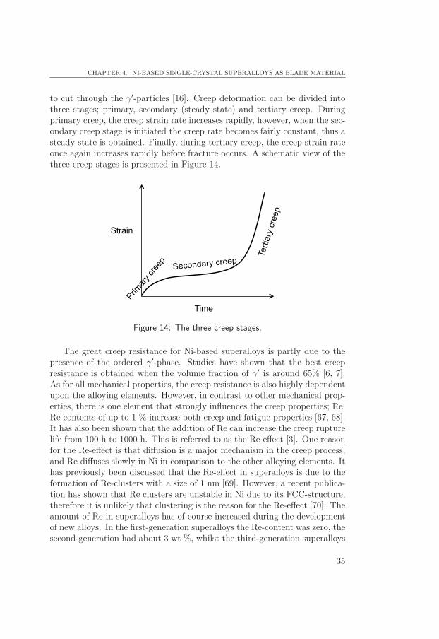
to cut through the γ′-particles [16]. Creep deformation can be divided intothree stages; primary, secondary (steady state) and tertiary creep. Duringprimary creep, the creep strain rate increases rapidly, however, when the sec-ondary creep stage is initiated the creep rate becomes fairly constant, thus asteady-state is obtained. Finally, during tertiary creep, the creep strain rateonce again increases rapidly before fracture occurs. A schematic view of thethree creep stages is presented in Figure 14.
Time
Strain
Primar
y cre
ep
Secondary creep Te
rtiar
y cr
eep
Figure 14: The three creep stages.
The great creep resistance for Ni-based superalloys is partly due to thepresence of the ordered γ′-phase. Studies have shown that the best creepresistance is obtained when the volume fraction of γ′ is around 65% [6, 7].As for all mechanical properties, the creep resistance is also highly dependentupon the alloying elements. However, in contrast to other mechanical prop-erties, there is one element that strongly influences the creep properties; Re.Re contents of up to 1 % increase both creep and fatigue properties [67, 68].It has also been shown that the addition of Re can increase the creep rupturelife from 100 h to 1000 h. This is referred to as the Re-effect [3]. One reasonfor the Re-effect is that diffusion is a major mechanism in the creep process,and Re diffuses slowly in Ni in comparison to the other alloying elements. Ithas previously been discussed that the Re-effect in superalloys is due to theformation of Re-clusters with a size of 1 nm [69]. However, a recent publica-tion has shown that Re clusters are unstable in Ni due to its FCC-structure,therefore it is unlikely that clustering is the reason for the Re-effect [70]. Theamount of Re in superalloys has of course increased during the developmentof new alloys. In the first-generation superalloys the Re-content was zero, thesecond-generation had about 3 wt %, whilst the third-generation superalloys
35
PART I. BACKGROUND AND THEORY
can contain Re-amounts up to 6 wt %. Creep tests at 850 °C and 500 MPahave shown that creep rupture lives have increased 10 times between the first-and third-generation superalloys. At higher temperatures but lower loads,1050 °C and 150 MPa, the creep rupture lives increased from 250 h to 1000 hbetween the two generations and the most substantial difference between thetwo generations is the amount of Re [3]. But if the amount of Re becomestoo great, formation of TCP phases can initiate, and this will deteriorate themechanical properties of the material. The strengthening elements, such asRe and W, will then gather in the TCP phases instead of in the γ-matrix,which leads to a decrease in creep deformation resistance.
Since single-crystal materials do not have any grain-boundaries, the creepbehaviour differs significantly between single-crystal and poly-crystal alloys[3]. For example, single-crystal superalloys rarely show a constant strainrate (secondary creep), instead the creep strain rate increases progressively.This behaviour has been demonstrated by Yu et al. [71] who studied hightemperature creep for the SRR99 Ni-based single-crystal superalloy. Creeptests at 700 °C showed a distinct primary creep stage, the secondary creepstage, or steady-state stage, was short before the tertiary creep initiated andfinished with failure. Creep tests at 900 °C were also performed, and the re-sults showed a shorter primary stage almost immediately followed by a longtertiary creep where the strain rate accelerated. In this case no steady-statestage was observed. Tsuno et al. [32] studied the creep and yield strengthtension/compression asymmetry for different Ni-based single-crystal super-alloys. For the two superalloys CMSX-4 and TMS75, an evident creep ten-sion/compression asymmetry was found. Tensile stresses at 700 °C inducedcreep strain caused by slip on the {111}〈112〉 system. However, under com-pression large creep strains were caused by mechanical twinning, both at 750°C and 950 °C. Research by Reed et al. [18] concerning high temperatureuniaxial creep for the single-crystal superalloy CMSX-4 loaded in the 〈001〉direction, shows a complete rafted γ/γ′-microstructure is obtained after 10 h.During this time, the creep rate decreases with increased strain. At a criticalstrain of 0.7 ± 0.3 %, the strain rate once again increases before failure isobserved. It has been shown that heat treatments can improve the creepproperties [8]. By heat treating the superalloy CMSX-2, aligned 0.45 μmcuboidal γ′-precipitates were achieved, leading to increased creep strength.Compared to irregular γ′-precipitates, the cuboidal γ′-precipitates showed ahomogeneous deformation, which explains the increase in creep strength.
36
5Experimental methods
In this chapter, the experimental methods used in this thesis are presented.The mechanical testing was performed at both Linköping University andSiemens Industrial Turbomachinery in Finspång, Sweden. However, all thesample preparation and microstructure investigations were conducted at LinköpingUniversity.
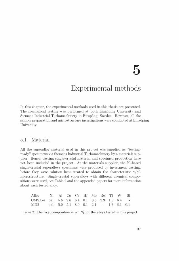
5.1 MaterialAll the superalloy material used in this project was supplied as ”testing-ready” specimens via Siemens Industrial Turbomachinery by a materials sup-plier. Hence, casting single-crystal material and specimen production havenot been included in the project. At the materials supplier, the Ni-basedsingle-crystal superalloys specimens were produced by investment casting,before they were solution heat treated to obtain the characteristic γ/γ′-microstructure. Single-crystal superalloys with different chemical compo-sitions were used, see Table 2 and the appended papers for more informationabout each tested alloy.
Alloy Ni Al Co Cr Hf Mo Re Ti W SiCMSX-4 bal. 5.6 9.6 6.4 0.1 0.6 2.9 1.0 6.4 -MD2 bal. 5.0 5.1 8.0 0.1 2.1 - 1.3 8.1 0.1
Table 2: Chemical composition in wt. % for the alloys tested in this project.
37
PART I. BACKGROUND AND THEORY
5.2 Thermomechanical fatigue testing
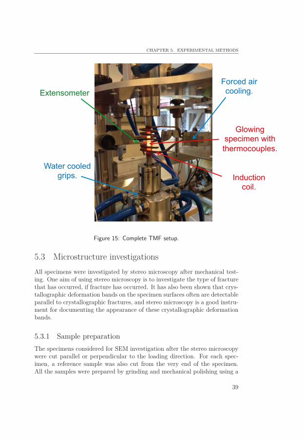
The TMF tests were conducted in a servo-hydraulic TMF machine from In-stron. All tests were performed in strain control. The reason for using straincontrolled instead of stress controlled TMF cycles, is to simulate more compo-nent like conditions. For a gas turbine blade in service at high temperature,the centrifugal forces due to the rotation are very high. In addition, severalhot-spots are observed. A hot-spot is a spot where the temperature is locallyvery high. During service, TMF damage is most connected to the thermalstresses in the hot-spots, and not often to the constant centrifugal forces.Further, the thermal expansion within a hot-spot is prevented by its coolersurrounding. This means that the deformation within a hot-spot on a realgas turbine blade in service is strain-controlled. Hence, performing straincontrolled TMF testing is more relevant than performing stress-controlledTMF testing. The fact that hot-spots are prevented from further expansionby their ”cooler” surroundings also explains why performing OP TMF cy-cling is more component like conditions compared to IP TMF cycles. SeeFigure 13 for the difference between IP and OP TMF. The TMF tests in thisthesis were performed in either IP and/or OP conditions. Induction heatingand forced air cooling was used to cycle the temperature. Thermo-coupleswere welded onto the specimens to control the actual specimen temperature.See Figure 15 for the complete TMF setup.
When performing testing, it is the mechanical strain, εmech, that is of in-terest. Therefore, during TMF testing, compensation for the thermal straininduced in the material by the temperature was made. When temperaturesaround 950 °C are applied, the thermal strain is about 1 % for superalloys.Hence, the thermal strain is sometimes almost at the level of the desired me-chanical strain. This shows the importance of compensating for the thermalstrain during TMF testing. The thermal strain, εth, is measured by runningone TMF cycle where only the temperature is cycled, before starting the realtest. To obtain the actual mechanical strain, εmech, the thermal strain εth issubsequently subtracted from the total strain, εtot, as follows:
εmech = εtot − εth = εtot − α(T − T0) (3)
where α is the thermal expansion coefficient of the material, T is the testtemperature and T0 is the reference temperature at the beginning of the test.
38
CHAPTER 5. EXPERIMENTAL METHODS
Forced air cooling.
Glowing specimen with thermocouples.
Induction coil.
Extensometer
Water cooled grips.
Figure 15: Complete TMF setup.
5.3 Microstructure investigationsAll specimens were investigated by stereo microscopy after mechanical test-ing. One aim of using stereo microscopy is to investigate the type of fracturethat has occurred, if fracture has occurred. It has also been shown that crys-tallographic deformation bands on the specimen surfaces often are detectableparallel to crystallographic fractures, and stereo microscopy is a good instru-ment for documenting the appearance of these crystallographic deformationbands.
5.3.1 Sample preparationThe specimens considered for SEM investigation after the stereo microscopywere cut parallel or perpendicular to the loading direction. For each spec-imen, a reference sample was also cut from the very end of the specimen.All the samples were prepared by grinding and mechanical polishing using a
39

PART I. BACKGROUND AND THEORY
Struer grinding and polishing machine. SiC grinding papers from #500 to#4000 were used before mechanical polishing with grains from 3 to 1/4 μmwas conducted. As the last step, chemical polishing was performed. For thework in this thesis, no samples were etched.
5.3.2 Scanning electron microscopyThe microstructure investigations that followed were performed in a scan-ning electron microscope (SEM) called Hitachi SU70 SEM. Here accelerationvoltages from 10 to 20 kV were used. When orientation imaging microscopy(OIM) was required, an electron back-scattering diffraction (EBSD) systemby HKL technology was used.
40
6Summary of papers included
Paper I
Deformation and damage mechanisms during thermomechani-cal fatigue of a single-crystal superalloy in the 〈001〉 and 〈011〉directions
The purpose of this paper was to investigate the differences in mechanicalresponse and microstructural behaviour when the Ni-based single-crystal su-peralloy CMSX-4 was subjected to TMF in two crystallographic directions,〈001〉 and 〈011〉. A strain controlled OP TMF cycle with Rε = -∞ in thetemperature range 100 to 850 °C was used.
As expected, when loaded in the 〈001〉 direction, the material exhibiteda higher number of cycles to failure compared to the 〈011〉 direction, whenequivalent strain ranges were compared. High strain ranges led to crystallo-graphic fractures along one of the {111} planes while low strain ranges led tonon-crystallographic fractures. This result was valid for both the 〈001〉 and〈011〉 directions. Specimens with random fractures showed recrystallizationclose to the fracture surface. Twinning was found to be a major deformationmechanism for most specimens. A change in deformation mechanism fromtwinning to shearing was found in specimens subjected to loading in the 〈011〉direction when moving from low to high strain ranges. This investigation alsoindicated that crack propagation is a consequence of recrystallization and notvice versa.
41
PART I. BACKGROUND AND THEORY
Paper II
Crystallographic orientation influence on the serrated yieldingbehaviour of a single-crystal superalloyIn this paper, the yielding behaviour at intermediate temperature in threedifferent crystal orientations for the Ni-based single-crystal superalloy MD2was investigated. The 〈001〉, 〈011〉 and 〈111〉 crystal orientations were testedin both tension and compression at 500 °C.
The 〈011〉 direction showed a serrated yielding, a significant tension/compresssionasymmetry in yield strength and visible deformation bands on the specimensurfaces. However, the 〈001〉 and 〈111〉 directions showed a more homo-geneous yielding, less tension/compression asymmetry and no deformationbands. Microstructure investigations showed that the serrated yielding in the〈011〉 direction can be attributed to the appearance of DSA and that onlyone slip system is active in this direction during plastic deformation.
Paper III
Creep and stress relaxation anisotropy of a single-crystal super-alloyIn this study, the high temperature creep and stress relaxation behaviourof a Ni-based single-crystal superalloy was studied. The aim of the studywas to investigate and compare creep rates from stress relaxation tests withconventional constant load creep tests. In addition, the influence by TMFcycling on the creep rates was studied. Material with three different crystalorientations were tested; 〈001〉, 〈011〉 and 〈111〉 respectively, and the stressrelaxation tests were performed in both tension and compression.
The results indicated a clear anisotropic creep behaviour as well as a ten-sion/compression asymmetry during stress relaxation at both 750 and 950 °C.Generally, the 〈001〉 direction seemed to have the best creep properties of alldirections. From the conventional creep tests, the 〈011〉 direction showed verylow creep ductility compared to the other directions and also crystallographicfractures. The 〈001〉 direction shows the greatest tension/compression asym-metry in creep rate during stress relaxation. TMF cycling seems to increasethe creep rate temporary, but after some time, the creep rate seems to de-crease again and seems to adapt to the pre-unloading creep rate. Creep ratesfrom stress relaxation tests agree very well with creep rates from the con-ventional constant load creep tests. This finding is very useful since stress
42

CHAPTER 6. SUMMARY OF PAPERS INCLUDED
relaxation tests are generally much shorter than creep tests.
43

7Conclusions
The research presented in this licentiate thesis deals with high temperatureproperties of Ni-based single-crystal superalloys with a focus on the differencebetween different crystal orientations. It was found that the deformationduring TMF cycling in single-crystal superalloys is very localized for boththe 〈001〉 and 〈011〉 directions. Moreover, for both directions twinning is amajor deformation mechanism during OP TMF cycling. However, the samestudy shows that the major deformation mechanism changes from twinningto shearing in the γ/γ′-microstructure for the 〈011〉 direction, when movingfrom low to high strain ranges.
By performing TMF tests with 100 h hold times during each cycle, itwas shown that similar creep rates can be obtained from TMF tests asfrom conventional constant load creep tests. Creep rates are for exampleneeded when performing material modelling of TMF behaviour, and if thosecan be obtained in a way which is more time efficient, it is very useful.The same study showed that the 〈001〉 direction shows a significant ten-sion/compression asymmetry during stress relaxation at 750°C. At this tem-perature the creep rate is about 10 times higher in compression than tension.It was also shown that TMF cycling seems to influence the creep rates.
It has also been found that the 〈011〉 direction shows a serrated yieldingbehaviour at intermediate temperature. However, the other two main crystalorientations, 〈001〉 and 〈111〉, show a more stable yielding at this temper-ature. There can be several reasons for the serrated yielding shown by the〈011〉 direction, but one major factor was found to be the occurrence of DSAwithin localized deformation bands.
45

8Future work
This licentiate thesis is one step towards a Ph.D. thesis, which is planned tobe finalized during 2015. The continuation of the research will be conductedwithin the same project as this licentiate thesis, and deal with high temper-ature properties of Ni-based single-crystal superalloys. However, the futurework will focus predominantly on TMF properties of Ni-based single-crystalsuperalloys.
The yielding and creep relaxation behaviour of the MD2 superalloy werestudied in Paper II and III respectively. Already in progress is TMF testingto fracture of the same alloy. Both the 〈001〉 and 〈011〉 directions are tested,and the occurring deformation and damage mechanisms will be studied.
Further, TMF testing of the single-crystal version of STAL15 will beperformed. STAL15 is a new superalloy, developed by Siemens IndustrialTurbomachinery [72]. This alloy can be casted in both poly-crystal andsingle-crystal form. However, it is the STAL15 in single-crystal form thatwill be the focus for future research in this project. The TMF behaviouras well as the deformation and damage mechanisms that occur during TMFconditions will be studied. Also here, the two different crystal orientations〈001〉 and 〈011〉 will be tested.
In addition, studies of TMF damage to real turbine blade components areplanned. Siemens Industrial Turbomachinery will provide gas turbine bladesthat have been in service, and the aim is to compare TMF damage from realturbine blades to TMF damage from laboratory testing.
47

Bibliography
[1] D. Leidermark, Crystal plasticity and crack initiation in a single-crystalnickel-base superalloy. Modelling, evaluation and applications. PhD the-sis, Linköping University, 2011.
[2] R. C. Reed, T. Tao, and N. Warnken, “Alloys-by-design: Application tonickel-based single crystal superalloys,” Acta Materialia, vol. 57, no. 19,pp. 5898–5913, 2009.
[3] R. C. Reed, The Superalloys - Fundamentals and Applications. Cam-bridge: Cambridge University Press, 2006.
[4] F. R. N. Nabarro and H. L. de Villiers, The physics of Creep - Creepand Creep-resistant Alloys. 1st ed., 1995.
[5] H. Mughrabi, “Microstructural aspects of high temperature deforma-tion of monocrystalline nickel base superalloys: Some open problems,”Materials Science and Technology, vol. 25, no. 2, pp. 191–204, 2009.
[6] T. Murakumo, T. Kobayashi, Y. Koizumi, and H. Harada, “Creep be-haviour of Ni-base single-crystal superalloys with various γ′ volume frac-tion,” Acta Materialia, vol. 52, no. 12, pp. 3737–3744, 2004.
[7] Y. Ro, Y. Koizumi, and H. Harada, “High temperature tensile propertiesof a series of nickel-base superalloys on a γ/γ′ tie line,” Materials Scienceand Engineering: A, vol. 223, no. 1-2, pp. 59–63, 1997.
[8] P. Caron and T. Khan, “Improvement of creep strength in a nickel-base single-crystal superalloy by heat treatment,” Materials Science andEngineering, vol. 61, no. 2, pp. 173–184, 1983.
[9] R. A. Ricks, A. J. Porter, and R. C. Ecob, “The growth of γ′ precipitatesin nickel-base superalloys,” Acta Metallurgica, vol. 31, no. 1, pp. 43–53,1983.
49

PART I. BACKGROUND AND THEORY
[10] C. M. F. Rae and R. C. Reed, “The precipitation of topologicallyclose-packed phases in rhenium-containing superalloys,” Acta Materi-alia, vol. 49, no. 19, pp. 4113–4125, 2001.
[11] T. Sugui, W. Minggang, L. Tang, Q. Benjiang, and X. Jun, “Influ-ence of tcp phase and its morphology on creep properties of singel-crystal nickel-based superalloys,” Materials Science and Engineering A,vol. 527, pp. 5444–5451, 2010.
[12] A. Sato, H. Harada, T. Yokokawa, T. Murakumo, Y. Koizumi,T. Kobayashi, and H. Imai, “The effects of ruthenium on the phasestability of fourth generation Ni-base single-crystal superalloy,” ScriptaMaterialia, vol. 54, pp. 1679–1684, 2006.
[13] T. M. Pollock and S. Tin, “Nickel-based superalloys for advanced tur-bine engines: Chemistry, microstructure, and properties,” Journal ofPropulsion and Power, vol. 22, no. 2, pp. 361–374, 2006.
[14] K. Durst and M. Göken, “Micromechanical characterisation of the influ-ence of rhenium on the mechanical properties in nickel-base superalloys,”Materials Science and Engineering A, vol. 387-389, pp. 312–316, 2004.
[15] L. Huang, X. F. Sun, H. R. Guan, and Z. Q. Hu, “Effect of rhenium ad-dition on isothermal oxidation behavior of single-crystal Ni-based super-alloy,” Surface and Coatings Technology, vol. 200, no. 24, pp. 6863–6870,2006.
[16] R. W. Herzberg, Deformation and Fracture Mechanics of EngineeringMaterials. 4th ed., 1996.
[17] S. Draper, D. Hull, and R. Dreshfield, “Observations of directionalγ′ coarsening during engine operation,” Metallurgical Transactions A,vol. 20, no. 4, pp. 683–688, 1989.
[18] R. C. Reed, N. Matan, D. C. Cox, M. A. Rist, and C. M. F. Rae,“Creep of CMSX-4 superalloy single crystals: effects of rafting at hightemperature,” Acta Materialia, vol. 47, no. 12, pp. 3367–3381, 1999.
[19] D. Leidermark, J. J. Moverare, S. Johansson, K. Simonsson, andS. Sjöström, “Tension/compression asymmetry of a single-crystal su-peralloy in virgin and degraded condition,” Acta Materialia, vol. 58,no. 15, pp. 4986–4997, 2010.
50
BIBLIOGRAPHY
[20] A. Epishin, T. Link, H. Klingelhöffer, B. Fedelich, U. Brückner, andP. D. Portella, “New technique for characterization of microstructuraldegradation under creep: Application to the nickel-base superalloyCMSX-4,” Materials Science and Engineering: A, vol. 510-511, pp. 262–265, 2009.
[21] M. Ignat, J. Y. Buffiere, and J. M. Chaix, “Microstructures inducedby a stress gradient in a nickel-based superalloy,” Acta Metallurgica etMaterialia, vol. 41, no. 3, pp. 855–862, 1993.
[22] U. Tetzlaff and H. Mughrabi, “Enhancement of the high-temperaturetensile creep strength of monocrystalline nickel-base superalloys by pre-rafting in compression,” in Superalloys 2000 (T. M. Pollock, R. D.Kissinger, R. R. Bowman, K. A. Green, M. McLean, S. Olson, andJ. J. Schirra, eds.), pp. 273–282, The Minerals, Metals and MaterialsSociety, 2000.
[23] F. C. Neuner, U. Tetzlaff, and H. Mughrabi, “Enhancement of thermo-mechanical fatigue resistance of a monocrystalline nickel-base superalloyby pre-rafting,” in Thermomechanical fatigue of Materials, ASTM STP1428, pp. 112–126, 2003.
[24] R. A. Mulford and D. P. Pope, “The yield stress of Ni3(Al, W),” ActaMetallurgica, vol. 21, no. 10, pp. 1375–1380, 1973.
[25] E. Nembach, “The high temperature peak of the yield strength ofγ′-strengthened superalloys,” Materials Science and Engineering: A,vol. 429, no. 1-2, pp. 277–286, 2006.
[26] S. Takeuchi and E. Kuramoto, “Temperature and orientation depen-dence of the yield stress in Ni3Ga single crystals,” Acta Metallurgica,vol. 21, no. 4, pp. 415–425, 1973.
[27] S. M. Copley, B. H. Kear, and G. M. Rowe, “The temperature and ori-entation dependence of yielding in Mar-M200 single crystals,” MaterialsScience and Engineering, vol. 10, pp. 87–92, 1972.
[28] D. Hull and D. J. Bacon, Introduction to dislocations. 4th ed., 2001.
[29] C. Lall, S. Chin, and D. P. Pope, “The orientation and temperature de-pendence of the yield stress of Ni3(Al, Nb) single crystals,” MetallurgicalTransactions A, vol. 10, no. 9, pp. 1323–1332, 1979.
51

PART I. BACKGROUND AND THEORY
[30] M. Feller-Kniepmeier, T. Link, I. Poschmann, G. Scheunemann-Frerker,and C. Schulze, “Temperature dependence of deformation mechanisms ina single crystal nickel-base alloy with high volume fraction of γ′ phase,”Acta Materialia, vol. 44, no. 6, pp. 2397–2407, 1996.
[31] Q. Qin and J. L. Bassani, “Non-schmid yield behavior in single crystals,”Journal of the Mechanics and Physics of Solids, vol. 40, no. 4, pp. 813–833, 1992.
[32] N. Tsuno, S. Shimabayashi, K. Kakehi, C. M. F. Rae, and R. C. Reed,“Tension/compression asymmetry in yield and creep strengths of Ni-based superalloys,” in Superalloys 2008 (R. C. Reed, K. A. Green,P. Caron, T. P. Gabb, M. G. Fahrman, E. S. Huron, and S. A. Woodard,eds.), pp. 433–442, The Minerals, Metals and Materials Society, 2008.
[33] S. S. Ezz, D. P. Pope, and V. Vitek, “Asymmetry of plastic flow inNi3Ga single crystals,” Acta Metallurgica, vol. 35, no. 7, pp. 1879–1885,1987.
[34] S. S. Ezz, D. P. Pope, and V. Paidar, “The tension/compression flowstress asymmetry in Ni3(Al,Nb) single crystals,” Acta Metallurgica,vol. 30, no. 5, pp. 921–926, 1982.
[35] D. P. Pope and S. S. Ezz, “Mechanical properties of Ni3Al and nickel-base alloys with high volume fraction of γ′,” International metals re-views, vol. 29, no. 3, pp. 136–167, 1984.
[36] F. Jiao, D. Bettge, W. Österle, and J. Ziebs, “Tension-compressionasymmetry of the (001) single crystal nickel base superalloy SC16 un-der cyclic loading at elevated temperatures,” Acta Materialia, vol. 44,no. 10, pp. 3933–3942, 1996.
[37] M. Yamashita and K. Kakehi, “Tension/compression asymmetry in yieldand creep strengths of Ni-based superalloy with a high amount of tan-talum,” Scripta Materialia, vol. 55, no. 2, pp. 139–142, 2006.
[38] T. Ichitsubo, D. Koumoto, M. Hirao, K. Tanaka, M. Osawa,T. Yokokawa, and H. Harada, “Elastic anisotropy of rafted Ni-basesuperalloy at high temperatures,” Acta Materialia, vol. 51, no. 16,pp. 4863–4869, 2003.
[39] P. Caron, D. Cornu, T. Khan, and J. M. de Monicault, “Developmentof a hydrogen resistant superalloy for single crystal blade application inrocket engine turbopumps,” in Superalloys 1996 (R. D. Kissinger, D. J.
52
BIBLIOGRAPHY
Deye, D. L. Anton, A. D. Cetel, M. V. Nathal, T. M. Pollock, and D. A.Woodard, eds.), pp. 53–60, The Minerals, Metals and Materials Society,1996.
[40] R. V. Miner, R. C. Voigt, J. Gayda, and T. P. Gabb, “Orientation andtemperature dependence of Some Mechanical Properties of the Single-Crystal Nickel-Base Superalloy René N4: Part I. Tensile Behavior,”Metallurgical Transactions A, vol. 17A, pp. 491–496, 1986.
[41] T. S. Rong, “Serrated yielding in the B2-ordered Nb-15Al-20V alloy,”Intermetallics, vol. 11, pp. 151–155, 2003.
[42] X. Wu, J. H. Zhang, J. L. Liu, T. Jin, Y. B. Xu, and Z. Hu, “Plasticdeformation inhomogeneity in a single-crystal nickel-base superalloy,”Materials Science and Engineering A, vol. 325, pp. 478–483, 2002.
[43] S. A. Nalawade, M. Sundararaman, R. Kishore, and J. G. Shah, “Theinfluence of aging on the serrated yielding phenomena in a nickel-basedsuperalloy,” Scripta Materialia, vol. 59, pp. 991–994, 2008.
[44] T. P. Gabb, J. Gayda, and R. V. Miner, “Orientation and tempera-ture dependence of Some Mechanical Properties of the Single-CrystalNickel-Base Superalloy René N4: Part II. Low Cycle Fatigue Behavior,”Metallurgical Transactions A, vol. 17A, pp. 497–505, 1986.
[45] R. V. Miner, T. P. Gabb, J. Gayda, and K. J. Hemker, “Orientation andtemperature dependence of Some Mechanical Properties of the Single-Crystal Nickel-Base Superalloy René N4: Part III. Tension-compressionasymmetry,” 1986.
[46] X. H. Li and J. Moverare, “The use of acoustic emission technology incoating ductility testing at variuos temperatures,” Proceeding of ASMETurbo Expo, 2004.
[47] E. F. Westbrooke, L. E. Forero, and F. Ebrahimi, “Slip analysis in a Ni-base superalloy,” Acta Materialia, vol. 53, no. 7, pp. 2137–2147, 2005.
[48] D. Chatterjee, N. Hazari, N. Das, and R. Mitra, “Microstructure andcreep behavior of DMS4-type nickel-based superalloy single crystals withorientations near 〈001〉 and 〈011〉,” Materials Science and EngineeringA, vol. 528, no. 2, pp. 604–613, 2010.
[49] P. Lukas, J. Cadek, V. Sustek, and L. Kunz, “Creep of CMSX-4 single-crystals of different crystal orientations in tension and compression,”Materials Science and Engineering A, vol. 208, pp. 149–157, 1996.
53
PART I. BACKGROUND AND THEORY
[50] K. Kakehi, “Tension/compression asymmetry in creep behavior of a Ni-based superalloy,” Scripta Materialia, vol. 41, pp. 461–465, 1999.
[51] K. Kakehi, “Effect of primary and secondary precipitates on creepstrength of Ni-base superalloy single-crystals,” Materials Science andEngineering A, vol. 278, pp. 135–141, 2000.
[52] T. P. Gabb and G. Welsch, “The high temperature deformation in cyclicloading of a single crystal nickel-base superalloy,” Acta Metallurgica,vol. 37, no. 9, pp. 2507–2516, 1989.
[53] M. Ott and H. Mughrabi, “Dependence of the high-temperature low-cycle fatigue behaviour of the monocrystalline nickel-base superalloysCMSX-4 and CMSX-6 on the γ/γ′-morphology,” Materials Science andEngineering: A, vol. 272, no. 1, pp. 24–30, 1999.
[54] H. Mughrabi and U. Tetzlaff, “Microstructure and high-temperaturestrength of monocrystalline nickel-base superalloys,” Advanced Engi-neering Materials, vol. 2, no. 6, pp. 319–326, 2000.
[55] M. Ott and H. Mughrabi, “Dependence of the isothermal fatiguebehaviour of a monocrystalline nickel-base superalloy on the γ/γ′-morphology,” Proceedings, FATIGUE, vol. 2, pp. 789–794, 1996.
[56] J. J. Moverare, M. Segersäll, A. Sato, S. Johansson, and R. C. Reed,“Thermomechanical fatigue of single-crystal superalloys: Influence ofcompositions and microstructure,” in Superalloys 2012 (E. S. Huron,R. C. Reed, M. Hardy, M. J. Mills, R. E. Montero, P. D. Portella, andJ. Talesman, eds.), pp. 369–377, The Minerals, Metals and MaterialsSociety, 2012.
[57] G. M. Han, J. J. Yu, X. F. Sun, and Z. Q. Hu, “Thermo-mechanicalfatigue behavior of a single-crystal nickel-based superalloy,” MaterialsScience and Engineering A, vol. 528, pp. 6217–6224, 2011.
[58] F. Liu, Z. G. Wang, S. H. Ai, Y. C. Wang, X. F. Sun, T. Jin, andH. R. Guan, “Thermo-mechanical fatigue of single crystal nickel-basedsuperalloy DD8,” Scripta Materialia, vol. 48, pp. 1265–1270, 5 2003.
[59] J. J. Moverare and S. Johansson, “Damage mechanisms of a high-Crsingle crystal superalloy during thermomechanical fatigue,” MaterialsScience and Engineering: A, vol. 527, no. 3, pp. 553–558, 2010.
54
BIBLIOGRAPHY
[60] J. J. Moverare, S. Johansson, and R. C. Reed, “Deformation and dam-age mechanisms during thermal–mechanical fatigue of a single-crystalsuperalloy,” Acta Materialia, vol. 57, no. 7, pp. 2266–2276, 2009.
[61] M. Segersäll, J. J. Moverare, K. Simonsson, and S. Johansson, “Defor-mation and damage mechanisms during thermomechanical fatigue of asingle-crystal superalloy in the 〈001〉 and 〈011〉 directions,” in Super-alloys 2012 (E. S. Huron, R. C. Reed, M. Hardy, M. J. Mills, R. E.Montero, P. D. Portella, and J. Talesman, eds.), pp. 215–223, The Min-erals, Metals and Materials Society, 2012.
[62] J. X. Zhang, H. Harada, Y. Koizumi, and T. Kobayashi, “Crack ap-pearance of single-crystal nickel-base superalloys after thermomechani-cal fatigue failure,” Scripta Materialia, vol. 61, no. 12, pp. 1105–1108,2009.
[63] J. X. Zhang, H. Harada, Y. Ro, and Y. Koizumi, “Superior thermo-mechanical fatigue property of a superalloy due to its heterogeneousmicrostructure,” Scripta Materialia, vol. 55, no. 8, pp. 731–734, 2006.
[64] J. X. Zhang, H. Harada, Y. Ro, Y. Koizumi, and T. Kobayashi, “Ther-momechanical fatigue mechanism in a modern single crystal nickel basesuperalloy TMS-82,” Acta Materialia, vol. 56, no. 13, pp. 2975–2987,2008.
[65] J. X. Zhang, Y. Ro, H. Zhou, and H. Harada, “Deformation twins andfailure due to thermo-mechanical cycling in TMS-75 superalloy,” ScriptaMaterialia, vol. 54, pp. 655–660, 2006.
[66] H. U. Hong, J. G. Kang, B. G. Choi, I. S. Kim, Y. S. Yoo, and C. Y.Jo, “A comparative study on thermomechanical and low cycle fatiguefailures of a single crystal nickel-based superalloy,” International Journalof Fatigue, vol. 33, pp. 1592–1599, 12 2011.
[67] D. L. Anton and F. D. Lemkey, “Quinary alloy modification of the eu-tectic superalloy γ/γ′ + Cr3C2,” in Superalloys 1984 (M. Gell, C. S.Kortovich, R. H. Bricknell, W. B. Kent, and J. F. Radavich, eds.),pp. 601–610, The Minerals, Metals and Materials Society, 1984.
[68] A. F. Giamei and D. L. Anton, “Rhenium additions to a Ni-base su-peralloy: Effects on the microstructure,” Metallurgical Transactions A,vol. 16A, pp. 1997–2005, 1985.
55
PART I. BACKGROUND AND THEORY
[69] D. Blavette, P. Caron, and T. Khan, “An atom probe investigation ofthe role of rhenium additions in improving creep resistance of Ni-basesuperalloys,” Scripta Metallurgica, vol. 20, pp. 1395–1400, 1986.
[70] A. Mottura, M. W. Finnis, and R. C. Reed, “On the possibility of rhe-nium clustering in nickel-based superalloys,” Acta Materialia, vol. 60,pp. 2866–2872, 2012.
[71] J. Yu, X. Sun, T. Jin, N. Zhao, H. Guan, and Z. Hu, “High tempera-ture creep and low cycle fatigue of a nickel-base superalloy,” MaterialsScience and Engineering: A, vol. 527, no. 9, pp. 2379–2389, 2010.
[72] R. C. Reed, J. J. Moverare, A. Sato, F. Karlsson, and M. Hasselqvist,“A new single-crystal superalloy for power generation applications,” inSuperalloys 2012 (E. S. Huron, R. C. Reed, M. Hardy, M. J. Mills,R. E. Montero, P. D. Portella, and J. Talesman, eds.), pp. 197–204, TheMinerals, Metals and Materials Society, 2012.
56


![Surface recrystallization of single crystal nickel-based ...recrystallization behavior of SC superalloys are rarely reported [9,10]. Typically, recrystallization behavior of alloys](https://img.pdfslide.us/doc/110x75/5f2652b9bf73cd24c24d8552/surface-recrystallization-of-single-crystal-nickel-based-recrystallization-behavior.jpg)