Embed Size (px)
Citation preview

CO
E-00
17 ©
ABB
AS, A
utom
atio
n Te
chno
logi
es D
ivis
ion
-1-
Power From Shore:An introduction to HVDC Light® Offshore
Lead Competence Centerpresentation

CO
E-0
017
©A
BB
Aut
omat
ion
Tech
nolo
gies
Div
isio
n -
2
Presentation overview:
1. HVDC Light®
2. Offshore gen. Vs. power from shore3. Offshore transmission applications4. Cables5. Very High Voltage motors (Motorformers)6. Converter station optimized for platforms7. Troll-A HVDC Light8. References

CO
E-0
017
©A
BB
Aut
omat
ion
Tech
nolo
gies
Div
isio
n -
3
1. What is HVDC Light®?
! HVDC Light® is ABB’s Trademark for High Voltage Direct Current transmission system based on solid state Voltage Source Converter technology
! Utilizes most advanced power electronics and semiconductors! Power is transmitted via underground/undersea cables! More efficient way of transmitting power over distances above ~50
km (with respect to AC cable transmission)! The most versatile way of transmitting power in the range of 40-
500 MW
! ABB is the undisputed leader in the world-wide T&D market and in development of enabling technologies
! HVDC since 1954! HVDC Light since 1997

CO
E-0
017
©A
BB
Aut
omat
ion
Tech
nolo
gies
Div
isio
n -
4
1. Building blocks
Solid StatePower Electronics
Converters
DC cables
Synthesized AC power out at OffshoreAC power in from Onshore grid
From AC to DC
Onshorerectifier station
Offshoreinverter station
DC back to AC
Supp
ly g
ridO
ffshore receiving grid

CO
E-0
017
©A
BB
Aut
omat
ion
Tech
nolo
gies
Div
isio
n -
5
1. Attributes and Customer Value
! Simple and compact design with redundancies
! Operational versatility! Black start capability
! Power quality control
! Facilitates connections in remote areas without need for grid reinforcement
! Flexible modular systems that can be easily expanded to multi-terminal system
! Remotely controllable
! Robust, light-weight and oil-free cable system
" Significantly low OPEX with respect to GT:! High transmission efficiency: ~90-94%! Savings from reduction in gas emissions:
e.g. Troll A: 230’000 tons CO2
! Low O&M cost (by factor of 7-10)! Flexible planned maintenance! Remote controllability: less workers offshore! Quicker start-up time at commissioning! High uptime! Longer life time: 30 years
! Health Safety and Environmental impact! Removal of offshore gas turbines will significantly reduce risks and makes facilities inherently safer! Enclosed equipment gives efficient noise suppression

CO
E-0
017
©A
BB
Aut
omat
ion
Tech
nolo
gies
Div
isio
n -
6
2. Local Generation vs.. Power From ShoreLocal generation
! Pros! Single cycle turbines normally have lower CAPEX costs (investment costs)! Well proven concept
! Cons! Pollution: CO2, NOx and noise! Combine cycle weight > HVDC! Lower efficiency 30-40 % for new plants
Electric power from shore! Pros
! Have lower OPEX cost over years! No emissions generated on the platform; i.e. less pollution & no emission tax! HVDC platform space <= combined cycle system ! HVDC platform weight <= combined cycle system
! Cons ! Normally higher CAPEX then single cycle turbines

CO
E-0
017
©A
BB
Aut
omat
ion
Tech
nolo
gies
Div
isio
n -
7
2. Cost-benefit evaluation
OPEX Parameters to be considered:! Electrical/fuel energy price! Transmission/generating efficiency! Gas emission costs! O & M cost! Remote controllability (workers offshore)! Start-up time (commissioning)! Uptime (availability)! Life time! Interest rate
CAPEX Parameters to be considered:! Transmission power! Transmission distance! Platform integration! Water depth, sea-bed terrain! Cable hook-up to platform, j-tube or dynamic! Requirement of waste-heat recovery system
A FEED study is recommended for determination of accurate price
Power from shore versus offshore generation

CO
E-0
017
©A
BB
Aut
omat
ion
Tech
nolo
gies
Div
isio
n -
8
2. DC versus AC transmissionAC transmission! AC cables are not practical above short distances and 10s of MWs of
transmission power! Rapidly increasing loss & cable cost if distance increases
! Fault mitigation wrt problems in land network
! Power quality
! Large voltage variations on platform – if platform load is lost
! Static Var Compensators are needed to increase AC distances to 40 to 60 miles
DC transmission! Transmission distances from 10s to 100s of miles
! Transmission power from 10s to 100s MW
! “Black” receiving network
! Different frequency offshore / onshore
CO
E-0
017
©A
BB
Aut
omat
ion
Tech
nolo
gies
Div
isio
n -
9
2. Technology Selection: GT vs. AC vs. DC
Power(MW)
Distance(miles)
AC
Tra
nsm
issi
on
DC Transmission
Gas Turbines
An Example ofEconomical Window ofOpportunity for Power From Shore
2

CO
E-0
017
©A
BB
Aut
omat
ion
Tech
nolo
gies
Div
isio
n -
10
! 3a. Shore to platform! Serving single or cluster of platforms! Serving as variable speed drive to a single large motor load
! 3b. Platform to platform! Centralize generation capacity
! 3c. Offshore to shore! Connecting offshore power plant with shore grid
3. HVDC Light applications offshore

CO
E-0
017
©A
BB
Aut
omat
ion
Tech
nolo
gies
Div
isio
n -
11
3a. Serving single or cluster of platforms
30-700 MW
HVDC Light™
Offshore Onshore
HVDC Light™
Cluster
AC cables

CO
E-0
017
©A
BB
Aut
omat
ion
Tech
nolo
gies
Div
isio
n -
12
HVDC Light™
Offshore Onshore
HVDC Light™
Up to 45 MW
VHV Motor
Benefits of HV Motorformer:! Direct connection without transformer! Less switchgear needed
! HVDC Light™ + Motorformer™ = Adjustable Drive! Typical load: 20-50 MW compressors
3a. Serving as variable speed drive to a single large motor load

CO
E-0
017
©A
BB
Aut
omat
ion
Tech
nolo
gies
Div
isio
n -
13
3b. Platform to platform connections: Centralized generation
! Connection of platforms with different frequencies (50/60 Hz)
! Centralized generation capacity! Optimized operation: reduced
investment, Increased efficiency
30 - 700 MW
HVDC Light™ HVDC Light™Power transformerPower transformer

CO
E-0
017
©A
BB
Aut
omat
ion
Tech
nolo
gies
Div
isio
n -
14
3c. Connecting offshore power plant with shore grid
30 - 700 MW
HVDC Light™
Offshore Onshore
HVDC Light™Offshore generation
! Offshore power plant, power barges! Monetizing of stranded gas
CO
E-0
017
©A
BB
Aut
omat
ion
Tech
nolo
gies
Div
isio
n -
15
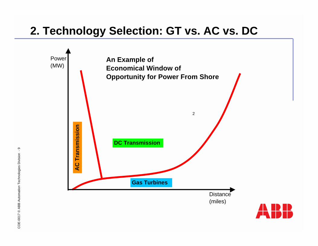
4. HVDC Light cables
! Strong and flexible cables! advantageous for laying at deep water! possible to use HVDC for dynamic floating platform applications
! Advantageous compared to AC-cables! higher transmission capacity! lower losses
ABB offers complete cable systems, including installation and engineering for offshore applications

CO
E-0
017
©A
BB
Aut
omat
ion
Tech
nolo
gies
Div
isio
n -
16
4. HVDC Light submarine cable
! Conductor of copper
! HVDC polymer insulation
! Lead alloy sheath
! Steel wire armor (when required)
! Complete cable- diameter 5-15 cm- weight 7.5 - 50 kg/m
! 6 - 550 MW per bi-pole
! Standard voltages: 84 and 150 kV
CO
E-0
017
©A
BB
Aut
omat
ion
Tech
nolo
gies
Div
isio
n -
17
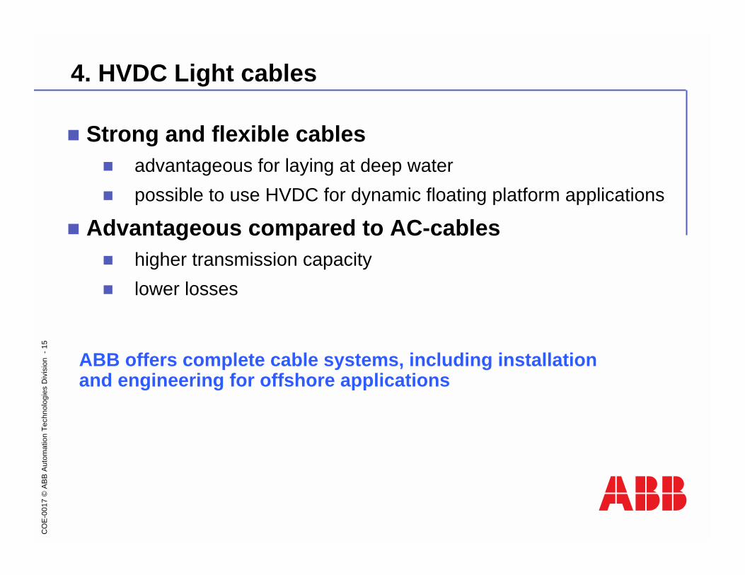
4. HVDC Light submarine cable - dynamic section (next)
! Conductor of copper
! HVDC polymer insulation
! Copper wire screen
! Swelling tapes and PE sheath
! Counter helical steel wire armor
! Complete cable- diameter 5-15 cm- weight 7.5 - 50 kg/m
! 6 - 550 MW per bi-pole
! Standard voltages: 84 and 150 kV

CO
E-0
017
©A
BB
Aut
omat
ion
Tech
nolo
gies
Div
isio
n -
18
4. Typical dynamic cable interface
~450 ft ~10 ft ~450 ft
Typical riser based systems
Dynamic part

CO
E-0
017
©A
BB
Aut
omat
ion
Tech
nolo
gies
Div
isio
n -
19
5. Very High Voltage motors: An ABB Innovation

CO
E-0
017
©A
BB
Aut
omat
ion
Tech
nolo
gies
Div
isio
n -
20
5. Benefits of Very High Voltage motors
! Reduced investment
! Reduced operating costs
! More environmentally friendly
! No transformer needed
! The HVDC Light inverter controls the motor
! Improved overload capacity
! Improved availability
! Less space than a conventional installation
! Higher efficiency
! Less civil work

CO
E-0
017
©A
BB
Aut
omat
ion
Tech
nolo
gies
Div
isio
n -
21
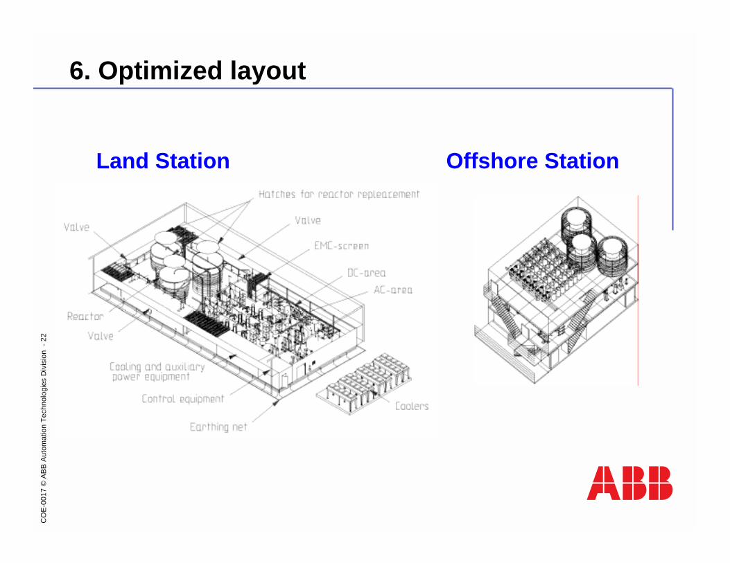
6. Optimized converter station for platforms
1) Excluding transformer(s), HVAC and external cooling eq.2) Excluding external access and stairways3) HVDC Light® Converter equipment
Typical Land Station1)
Volume2): 9,000 m3
Equipment weight3): 130 tonesTotal weight: Irrelevant
Volume 2): 4,000 m3
Equipment weight 3): 130 tonesTotal weight: 750 tones
Typical Offshore Station1)
Comparison, 2x40 MW HVDC Light®
Drawings not to scale
CO
E-0
017
©A
BB
Aut
omat
ion
Tech
nolo
gies
Div
isio
n -
22
6. Optimized layout
Land Station Offshore Station

CO
E-0
017
©A
BB
Aut
omat
ion
Tech
nolo
gies
Div
isio
n -
23
Submarine cables
Troll A platform station Kollsnes
land station
Norway Sweden
UK
7. Troll-A Power From Shore: World’s 1st Offshore HVDC system
Statoil’s Troll A Pre-compression projectKey platform data:! Troll A delivers gas to Kollsnes
from all Troll field platforms
! Total weight: 678 500 tones
! Height: 472 m (approx. 120 m above sea level)
! Current gas processing capacity:
100 million m3 per day

CO
E-0
017
©A
BB
Aut
omat
ion
Tech
nolo
gies
Div
isio
n -
24
HVDC Light Transmission & Electric Drive System
7. Troll-A HVDC Light in operation since October 2005
Key system data:! Two HVDC Light® transmission
systems
! Two 56-kV, 40-MW, 1800-rpm VHV Motors
! ± 60 kV DC
! 4x70 km sea cable
! Avoided emission of 230,000 tones CO2 annually
! Significantly reduced OPEX
! Significantly reduced risks associated with offshore gas turbines
! Reduced manning offshore due to the system’s remote controllability and low maintenance

CO
E-0
017
©A
BB
Aut
omat
ion
Tech
nolo
gies
Div
isio
n -
25
7. Troll A Electric Drive Systems
40 MW56 kV
132 kV SwitchboardKollsnes stationHVDC Light Rectifier
Subsea CableHVDC Light
Cable
Troll A stationHVDC Light Inverter
VHV Motor Compressor
Gear
±60 kV
70 km
Single Line Diagram

CO
E-0
017
©A
BB
Aut
omat
ion
Tech
nolo
gies
Div
isio
n -
26
7. Troll A HVDC Light® project: Novelties
Troll A:! First HVDC Light® based power supply from shore to platform
! First project with HVDC Light® feeding & driving a VHV Motor
! First installation of a VHV Motor offshore
! Largest VHV Motor built so far
While HVDC Light® and VHV Motor are both proven technologies....

CO
E-0
017
©A
BB
Aut
omat
ion
Tech
nolo
gies
Div
isio
n -
27
7. Troll A HVDC Light® EDS module
! Contains HVDC Light® equipment for systems 1 and 2
! 2 x 40 MW inverters, ± 60 kV DC
! Module dimensions:! Level 1: 22,5 x 12,5 m! Levels 2 & 3: 18,5 x 19 m! Height:
! Approx 15 m (module, only)! Approx 20 m (with HVAC)
! Dry weight:! Approx 750 tones (module and
equipment)
Barge after Load Out
Being lifted to Troll A platform
EDS module in production
HVDC Equipment

CO
E-0
017
©A
BB
Aut
omat
ion
Tech
nolo
gies
Div
isio
n -
28
7. Troll A Motorformer
! Rated voltage: 56 kV
! Rated current: 422 A
! Rated power: 40 MW
! Rated speed: 1800 rpm! Operating speed: 1260-1890
! Weight: 110 tones
Motorformer Being Installed
High Voltage Cable Windings

CO
E-0
017
©A
BB
Aut
omat
ion
Tech
nolo
gies
Div
isio
n -
29
7. Troll A HVDC Light Cable
! Conductor: Cu
! Cross section: 300 mm2
! Rated DC current: 540 A in air
! Insulation: Triple extruded DC
! Rated DC voltage: 80 kV
! Armoring: Double counter helix
! Outer diameter: 7.5 cm
! Dry weight: 15 kg/m

CO
E-0
017
©A
BB
Aut
omat
ion
Tech
nolo
gies
Div
isio
n -
30
7. Valhall HVDC Light Power From ShoreOperator: BPPartners: Amerada Hess, Shell, TotalTechnical DataCommissioning year: 2009Power rating: 78 MWAC Voltage: 300 kV / 11 kVDC Voltage: 150 kVLength of DC cable: 292 km
3-phase transformer
DC side area
Phase reactors AC
filters
Valve area
LxWxH = 22x15x13 meter
Valhall
Lista
New PH platform Existing WIP

CO
E-0
017
©A
BB
Aut
omat
ion
Tech
nolo
gies
Div
isio
n -
31
ABB is a global leader in power and automation technologies that enable
utility and industry customers to improve performance while lowering
environmental impact.

![IEEE TRANSACTIONS ON POWER SYSTEMS, 2019 1 Real-time LCC ... · to [2], LCC-HVDC projects still dominate the HVDC market of high power and voltage ratings, which can be up to 8 ˘12](https://img.pdfslide.us/doc/110x75/5f35791331488025cd53d2a4/ieee-transactions-on-power-systems-2019-1-real-time-lcc-to-2-lcc-hvdc-projects.jpg)

![Overview of the Configuration and Power Converters in High ... · Fig. 8. Basic scheme of the LCC-HVDC and VSC-HVDC transmission system [6]. Comparison of the CSC-HVDC and VSC-HVDC](https://img.pdfslide.us/doc/110x75/5ebc0e8dd027f5592e56ad65/overview-of-the-configuration-and-power-converters-in-high-fig-8-basic-scheme.jpg)