Embed Size (px)
Citation preview
INTERNATIONAL COUNCILON LARGE ELECTRIC SYSTEMS
INTRODUCTION TO HVDC
Presented by: Mojtaba MohaddesSC B4
August 22, 2016
08/08/2016
1
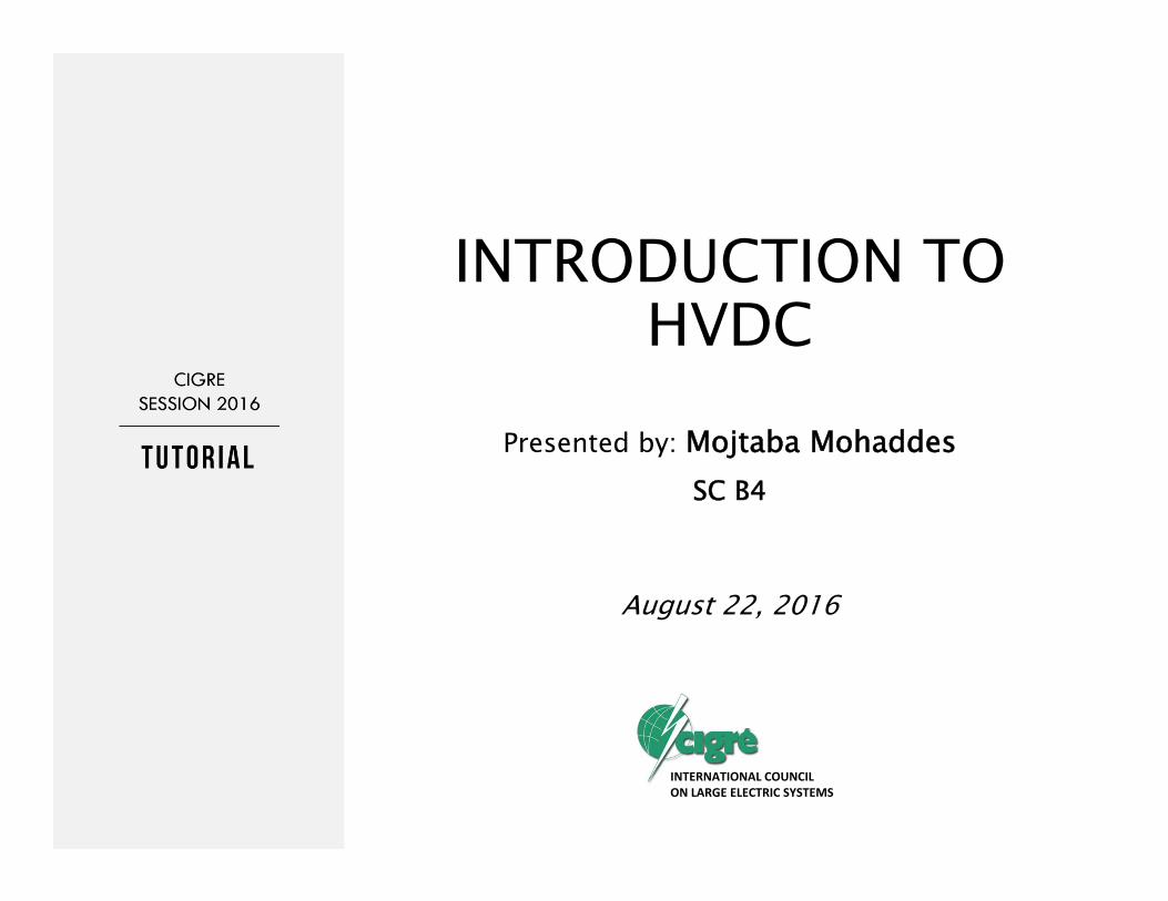
Presentation Layout
• Advantages of HVDC• HVDC Applications• HVDC Technology
• Line Commutated Converters• Voltage Sourced Converters
• Recent Developments• DC Grid
• Cigre Activities in HVDC
2
Advantages of HVDC
Sample HVdc and HVac Tower Configurations
Smaller towers
6.4m
6.9m
28.3
m28
.3m 16.9m4.6m7.8m
13m8.5m
11.3m
25.9m
17m
• HVDC towers are smaller and simpler than HVAC towers with similar transmission power rating
3
Advantages of HVDC
Typical transmission line right of way for 3000 MW if two ac towers are used
Narrow right of way
± 500 kV DC
60m
2 x 500 kV ac
110 m
4
08/08/2016
2
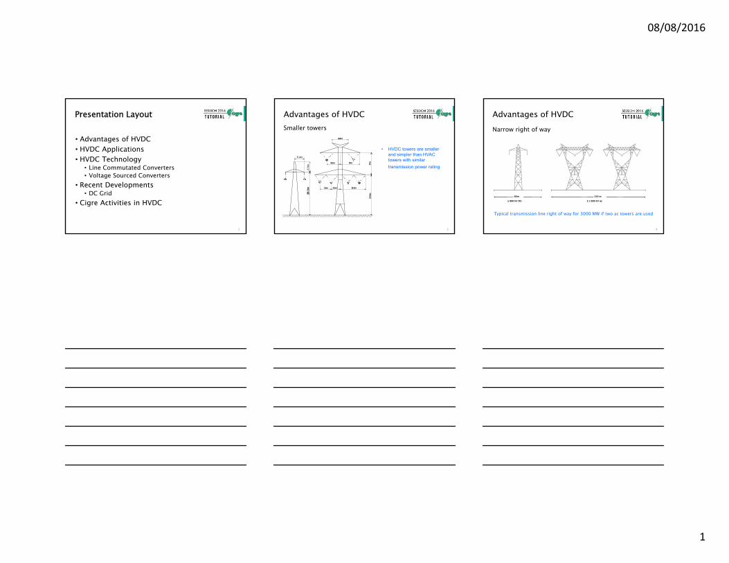
Advantages of HVDC
• No need for Series or Shunt Compensation
• Controllable power flow
• Zero or no contribution to short circuit current
5
Advantages of HVDC
Comparison of capital cost for HVDC and HVAC
distance
ac without compensation
HVdc
cost
Breakeven distance
6
Advantages of HVDC
Typical charging currents for land cables*
AC cables are limited in length due to the charging current, HVDC cables have no length limitation
Cross section (mm2)
Current rating (A)
Charging current (A/km)
* 500kV XLPE at 65C, flat formation
7
08/08/2016
3
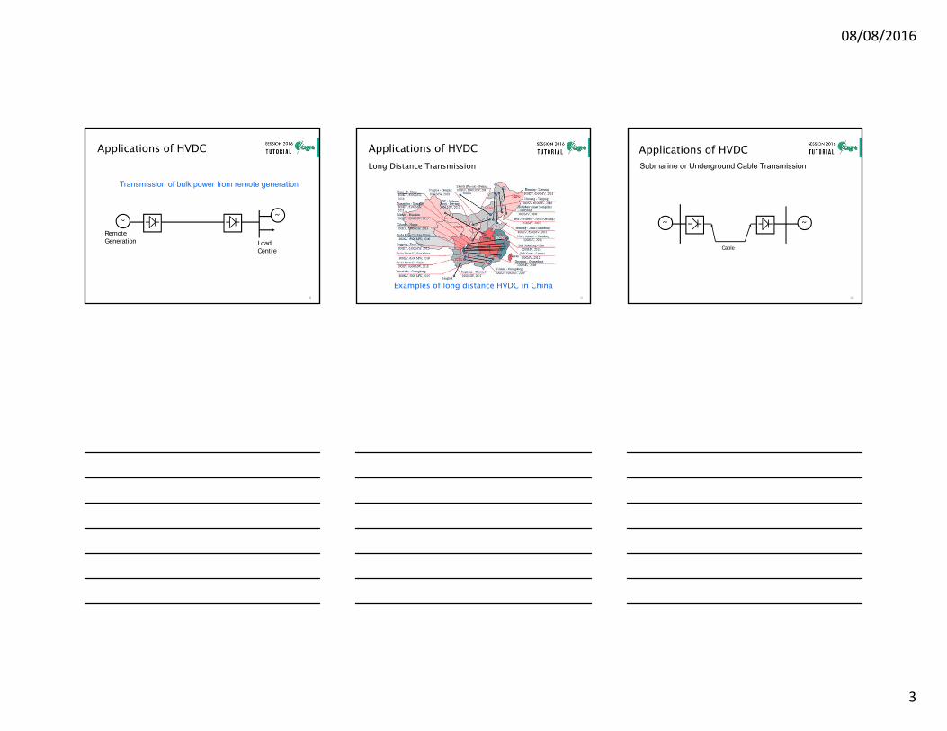
Transmission of bulk power from remote generation
~~
LoadCentre
RemoteGeneration
Applications of HVDC
8
Applications of HVDC
Examples of long distance HVDC in China
Long Distance Transmission
9
~ ~
Cable
Applications of HVDCSubmarine or Underground Cable Transmission
10
08/08/2016
4
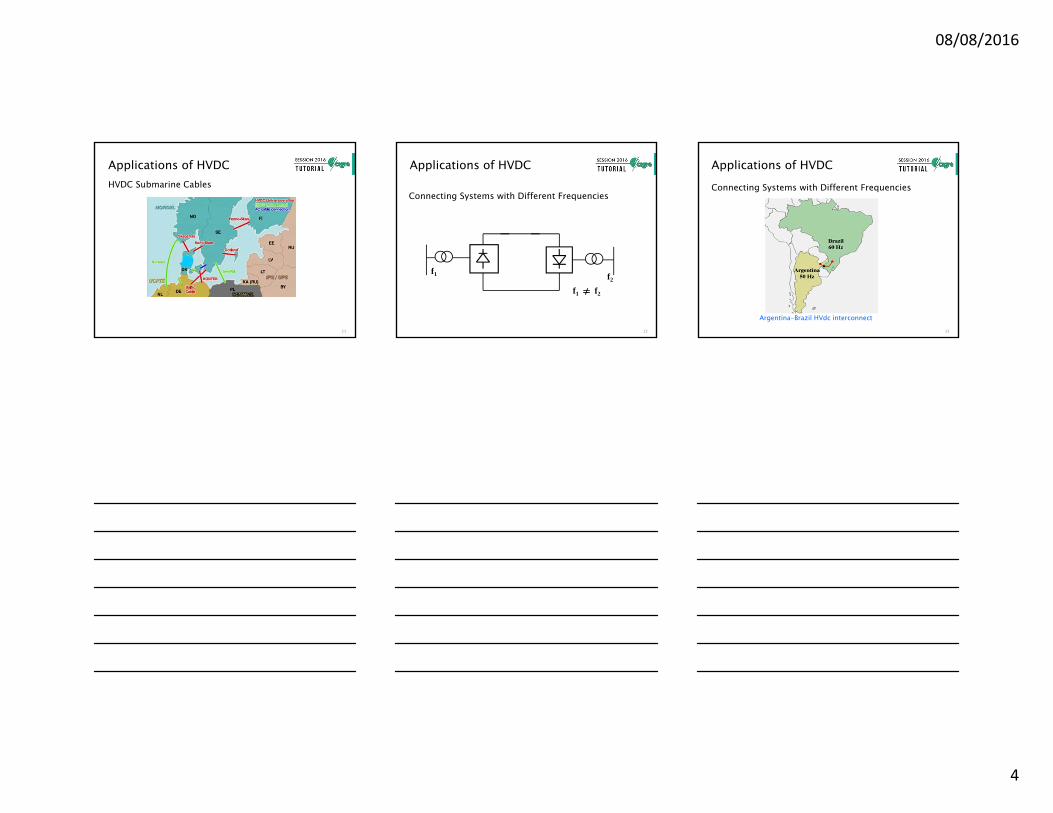
Applications of HVDC
Some of Northern Europe Cables(courtesy of Siemens)
HVDC Submarine Cables
11
f1 f2
f1 f2
Applications of HVDC
Connecting Systems with Different Frequencies
12
Applications of HVDC
Argentina-Brazil HVdc interconnect
Connecting Systems with Different Frequencies
13
08/08/2016
5
Applications of HVDC
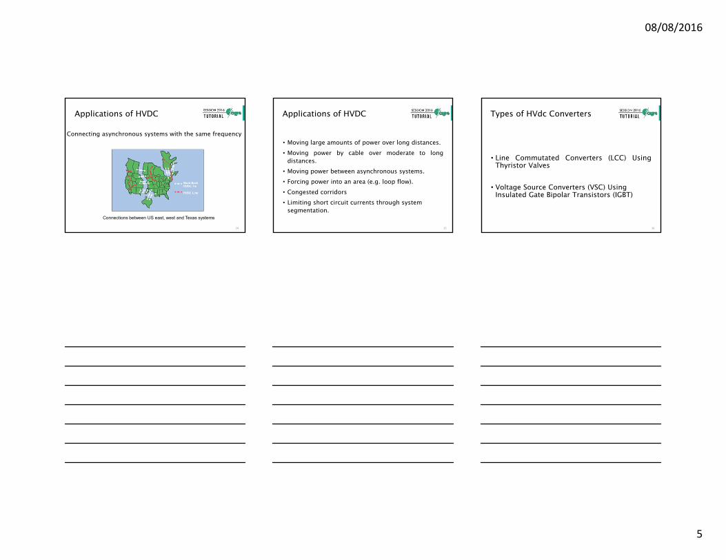
Connecting asynchronous systems with the same frequency
Connections between US east, west and Texas systems
14
• Moving large amounts of power over long distances.• Moving power by cable over moderate to long
distances.• Moving power between asynchronous systems.• Forcing power into an area (e.g. loop flow).• Congested corridors• Limiting short circuit currents through system
segmentation.
Applications of HVDC
15
Types of HVdc Converters
• Line Commutated Converters (LCC) UsingThyristor Valves
• Voltage Source Converters (VSC) Using Insulated Gate Bipolar Transistors (IGBT)
16
08/08/2016
6
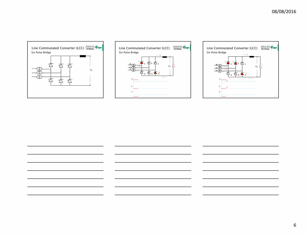
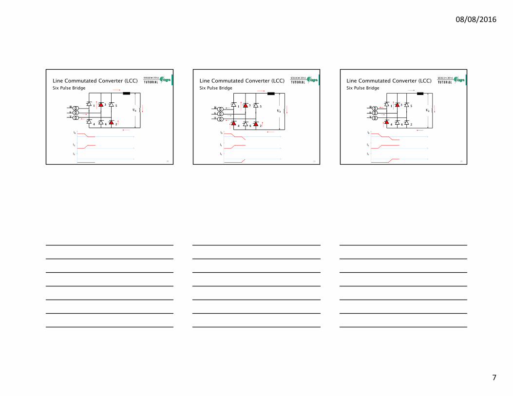
Line Commutated Converter (LCC)Six Pulse Bridge
Ud
17
Ud
1 3 5
4 6 2
R
ST
Line Commutated Converter (LCC)Six Pulse Bridge
IR
IS
IT
18
Ud
1 3 5
4 6 2
R
ST
Line Commutated Converter (LCC)Six Pulse Bridge
IR
IS
IT
19
08/08/2016
7
Ud
1 3 5
4 6 2
R
ST
Line Commutated Converter (LCC)Six Pulse Bridge
IR
IS
IT
20
Ud
1 3 5
4 6 2
R
ST
Line Commutated Converter (LCC)Six Pulse Bridge
IS
IT
IR
21
Ud
1 3 5
4 6 2
R
ST
Line Commutated Converter (LCC)Six Pulse Bridge
IS
IT
IR
22
08/08/2016
8
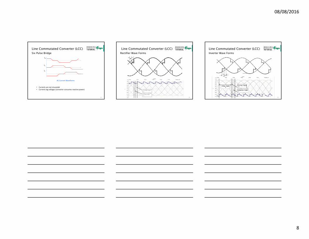
Line Commutated Converter (LCC)Six Pulse Bridge
IS
IT
IR
AC Current Waveforms
• Currents are not sinusoidal• Currents lag voltages (converter consumes reactive power)
23
Line Commutated Converter (LCC)Rectifier Wave Forms
F i r in g A n g le α
O v e r la p A n g le μ
24
Line Commutated Converter (LCC)Inverter Wave Forms
25
08/08/2016
9
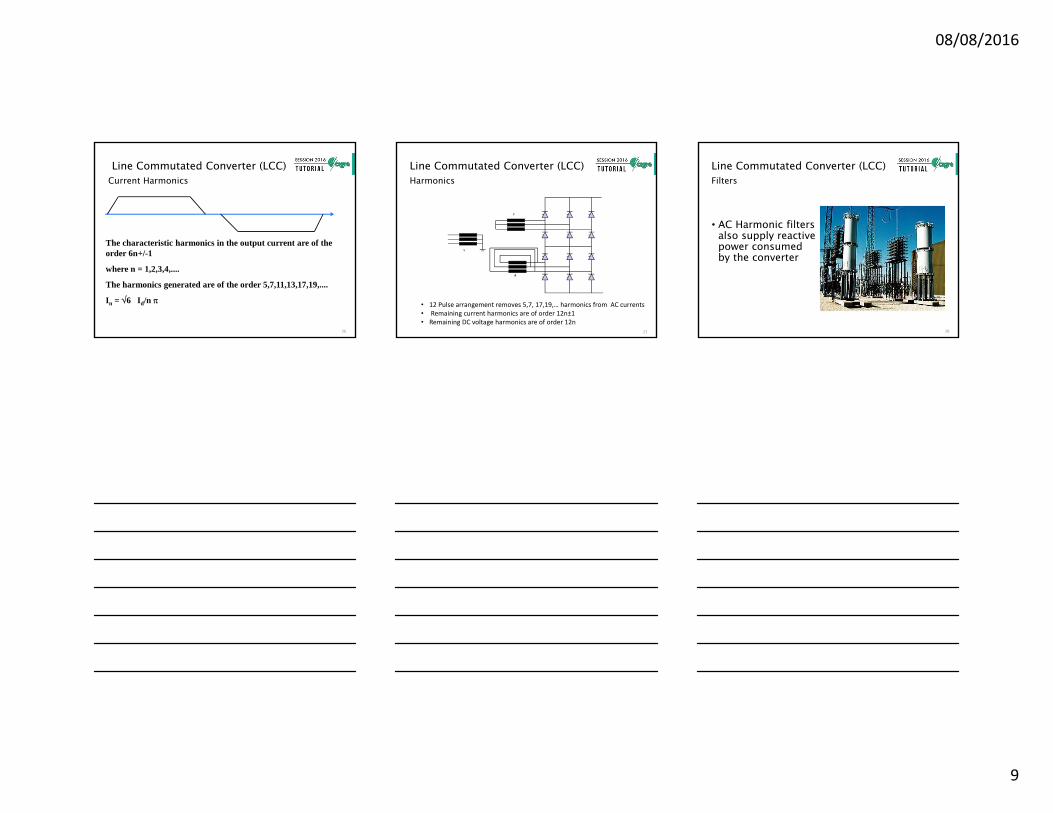
Line Commutated Converter (LCC)Current Harmonics
The characteristic harmonics in the output current are of the order 6n+/-1
where n = 1,2,3,4,....
The harmonics generated are of the order 5,7,11,13,17,19,....
In = 6 Id/n
26
Y
Y
Line Commutated Converter (LCC)Harmonics
• 12 Pulse arrangement removes 5,7, 17,19,… harmonics from AC currents• Remaining current harmonics are of order 12n±1• Remaining DC voltage harmonics are of order 12n
27
DC HarmonicsLine Commutated Converter (LCC)
• AC Harmonic filters also supply reactive power consumed by the converter
Filters
28
08/08/2016
10
Line Commutated Converter (LCC)
• Commutation failures are the result of the incomingvalve failing to take over the current, or re-fire of theoutgoing valve. Commutation failures are due to:
AC system faults & disturbances
DC faults or disturbances
Equipment failures
Inverter Commutation Failures
29
Line Commutated Converter (LCC)
• LCC requires certain level of ESCR, particularly atinverter
AC System Strength
)(PPower DC(S)MVA System (SCR) RatioCircuit Short dc
)(PPower DC)(Q MVAR Capacitive-(S)MVA System (ESCR) RatioCircuit Short Effective
dc
s
30
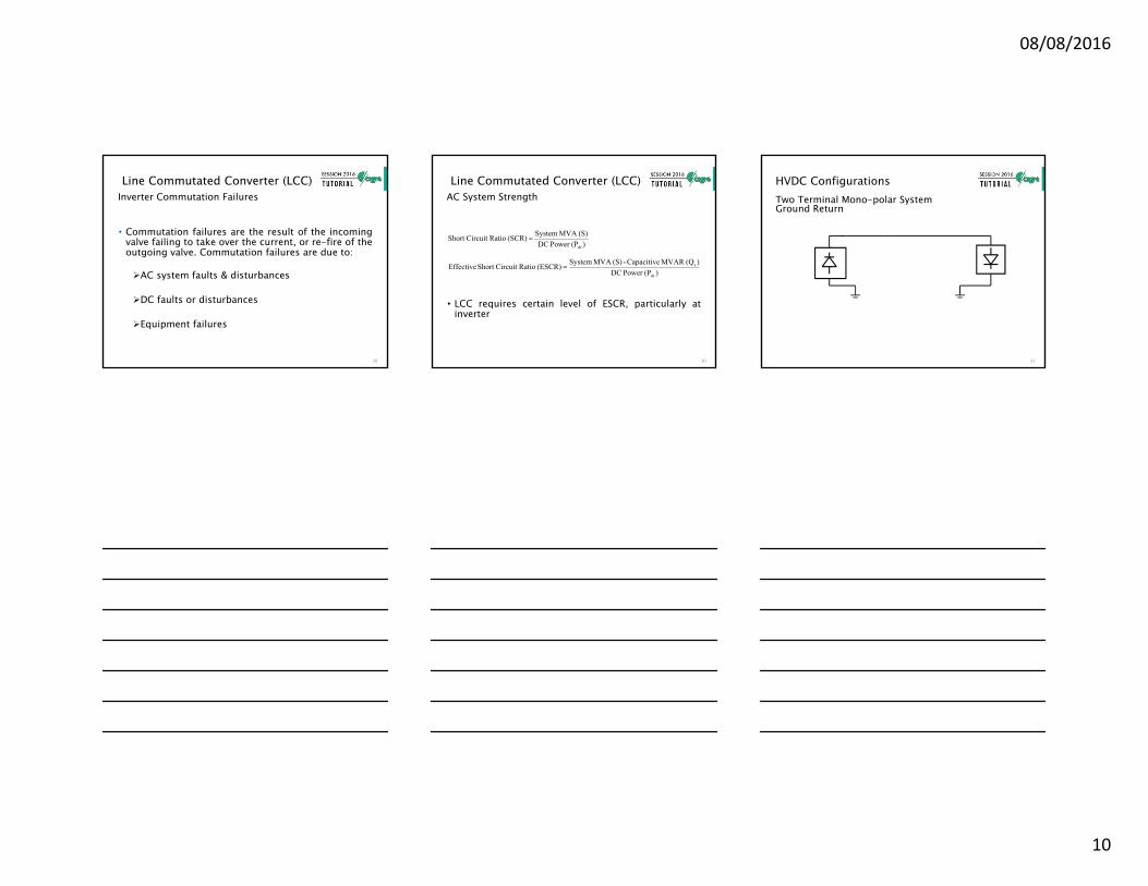
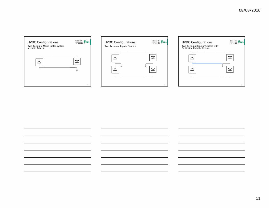
HVDC ConfigurationsTwo Terminal Mono-polar System Ground Return
31
08/08/2016
11
HVDC ConfigurationsTwo Terminal Mono-polar System Metallic Return
32
HVDC ConfigurationsTwo Terminal Bipolar System
33
HVDC ConfigurationsTwo Terminal Bipolar System with Dedicated Metallic Return
34
08/08/2016
12
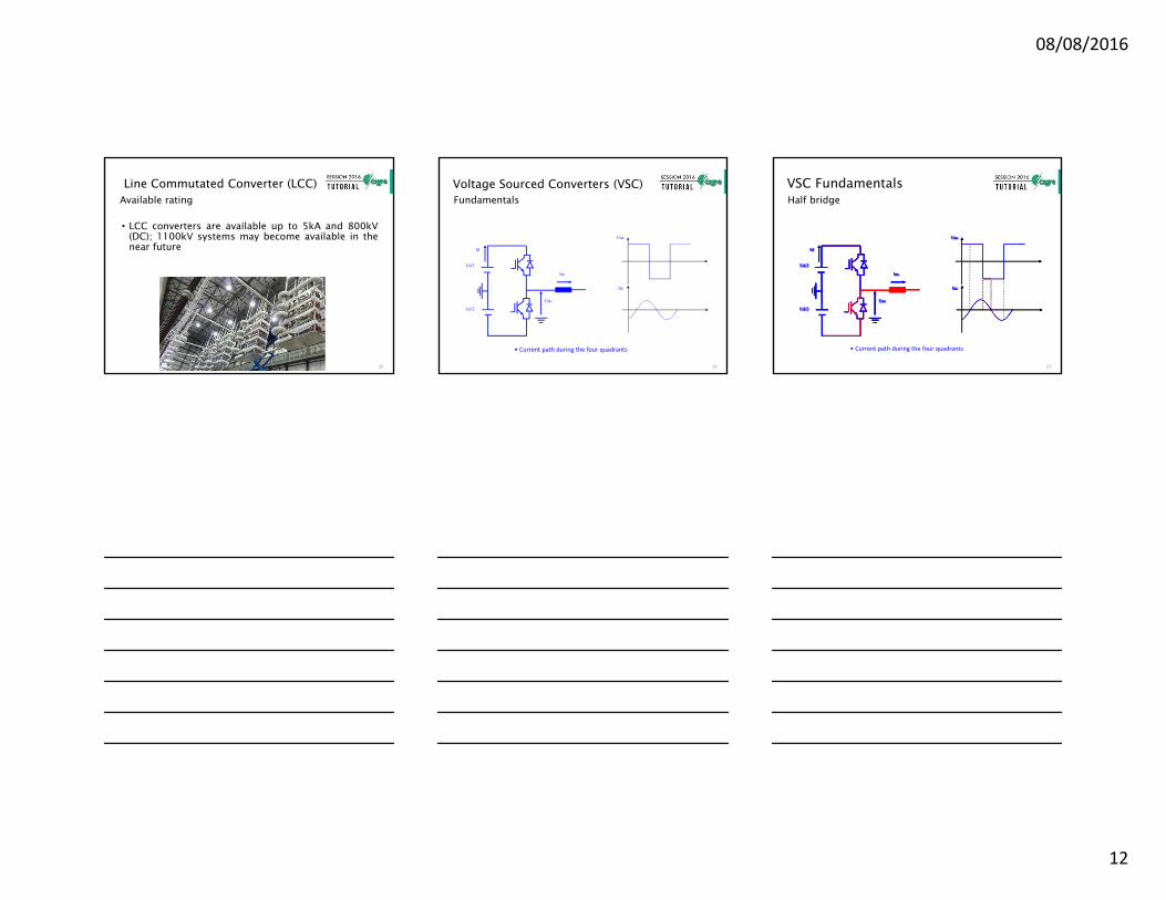
Line Commutated Converter (LCC)
• LCC converters are available up to 5kA and 800kV(DC); 1100kV systems may become available in thenear future
Available rating
35
Voltage Sourced Converters (VSC)Fundamentals
Ud/2
Id
Ud/2
Uac
Iac
Uac
Iac
• Current path during the four quadrants
36
VSC FundamentalsHalf bridge
Ud/2
Id
Ud/2
Uac
Iac
Uac
Iac
• Current path during the four quadrants
Ud/2
Id
Ud/2
Uac
Iac
Uac
Iac
Ud/2
Id
Ud/2
Uac
Iac
Uac
Iac
Ud/2
Id
Ud/2
Uac
Iac
Uac
Iac
37
08/08/2016
13
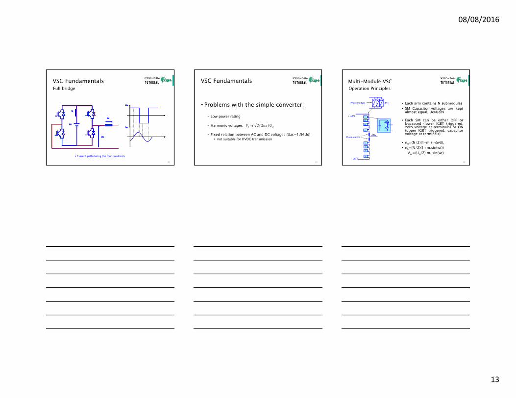
VSC FundamentalsFull bridge
• Current path during the four quadrants
Ud
Id
Uac
Iac
Uac
IacUd
Id
Uac
Iac
Uac
IacUd
Id
Uac
Iac
Uac
IacUd
Id
Uac
Iac
Uac
IacUd
Id
Uac
Iac
Uac
Iac
38
VSC Fundamentals
• Problems with the simple converter:
• Low power rating
• Harmonic voltages
• Fixed relation between AC and DC voltages (Uac=1.56Ud)• not suitable for HVDC transmission
Un/2(V dn )2
39
Multi-Module VSC
• Each arm contains N submodules• SM Capacitor voltages are kept
almost equal, Uc≈Ud/N
• Each SM can be either OFF orbypassed (lower IGBT triggered,zero voltage at terminals) or ON(upper IGBT triggered, capacitorvoltage at terminals)
• nu=(N/2)(1-m.sin(wt)),• nL=(N/2)(1+m.sin(wt))
Vac=(Ud/2).m. sin(wt)
Operation Principles
SM
SM
SM
SM
SM
SM
SM
SM
+ Ud/2
‐ Ud/2
~ ~ ~Phase module
Phase reactorIac
40
08/08/2016
14
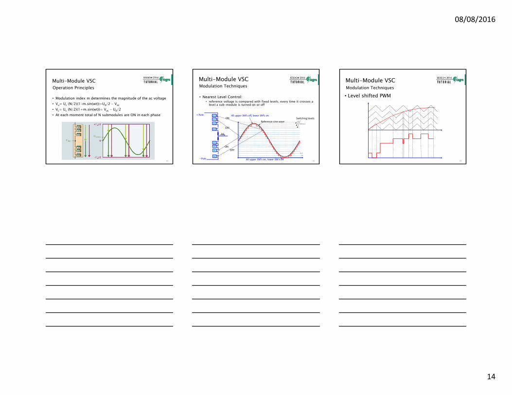
Multi-Module VSC
• Modulation index m determines the magnitude of the ac voltage• Vu= Uc (N/2)(1-m.sin(wt))=Ud/2 - Vac
• VL= Uc (N/2)(1+m.sin(wt))= Vac - Ud/2• At each moment total of N submodules are ON in each phase
Operation Principles
41
Multi-Module VSC
• Nearest Level Control:• reference voltage is compared with fixed levels, every time it crosses a
level a sub-module is turned on or off
Modulation Techniques
Reference sine waveSwitching levels
SM
SM
SM
SM
SM
SM
SM
SM
ON
OFF
+ Pole
‐ Pole
ON
OFF
All upper SM’s off, lower SM’s on
All upper SM’s on, lower SM’s off
Iac
Uc/2
3Uc/2
(2N‐1)Uc/2
42
Multi-Module VSC
• Level shifted PWMModulation Techniques
43
08/08/2016
15
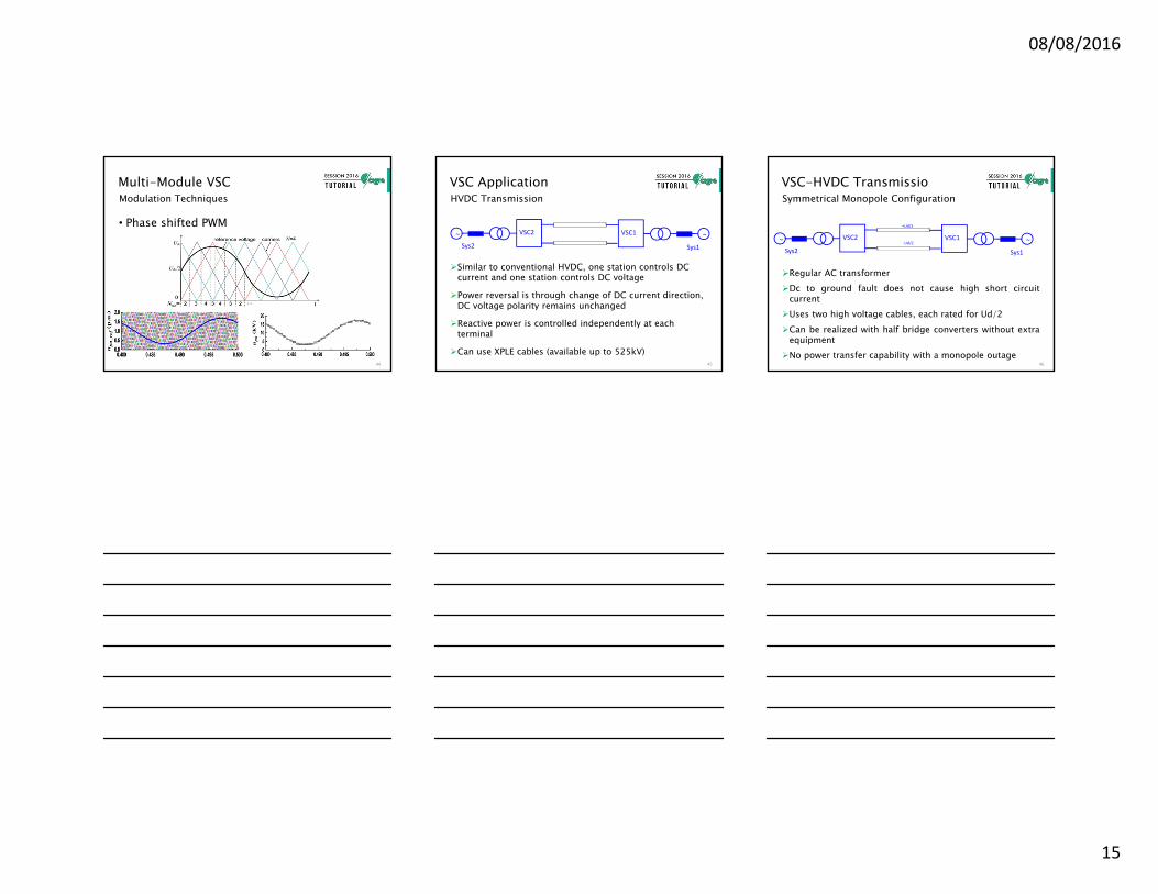
Multi-Module VSC
• Phase shifted PWM
Modulation Techniques
44
VSC Application
Similar to conventional HVDC, one station controls DC current and one station controls DC voltage
Power reversal is through change of DC current direction, DC voltage polarity remains unchanged
Reactive power is controlled independently at each terminal
Can use XPLE cables (available up to 525kV)
HVDC Transmission
VSC1 ~
Sys1
VSC2~Sys2
45
VSC-HVDC Transmissio
Regular AC transformerDc to ground fault does not cause high short circuit
currentUses two high voltage cables, each rated for Ud/2Can be realized with half bridge converters without extra
equipmentNo power transfer capability with a monopole outage
Symmetrical Monopole Configuration
VSC1 ~
Sys1
VSC2~Sys2
+Ud/2
‐Ud/2
46
08/08/2016
16
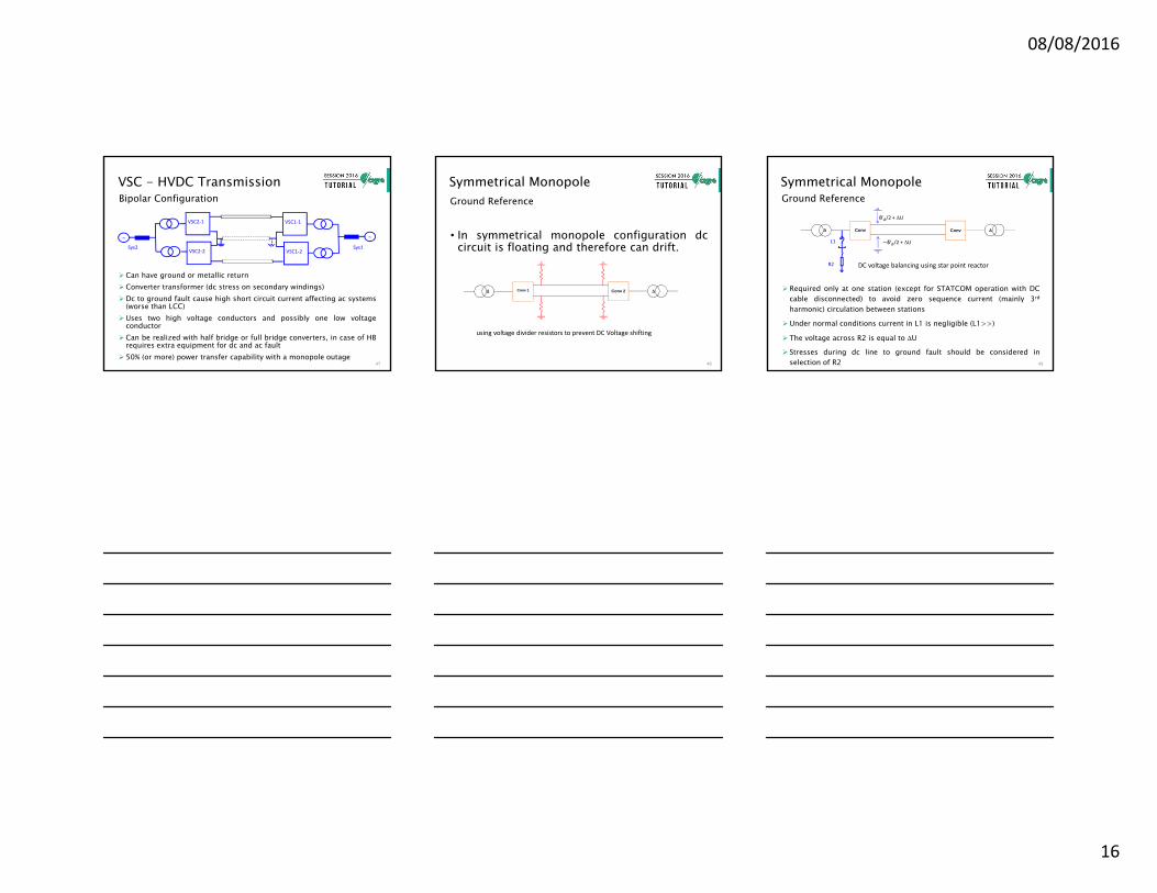
VSC - HVDC Transmission
Can have ground or metallic returnConverter transformer (dc stress on secondary windings)Dc to ground fault cause high short circuit current affecting ac systems
(worse than LCC)Uses two high voltage conductors and possibly one low voltage
conductorCan be realized with half bridge or full bridge converters, in case of HB
requires extra equipment for dc and ac fault 50% (or more) power transfer capability with a monopole outage
Bipolar Configuration
VSC1‐1
~
Sys1
VSC2‐1
~Sys2
VSC1‐2VSC2‐2
47
Symmetrical Monopole
• In symmetrical monopole configuration dccircuit is floating and therefore can drift.
Ground Reference
Conv 1 Conv 2
using voltage divider resistors to prevent DC Voltage shifting
48
Symmetrical Monopole
Required only at one station (except for STATCOM operation with DCcable disconnected) to avoid zero sequence current (mainly 3rd
harmonic) circulation between stations
Under normal conditions current in L1 is negligible (L1>>)
The voltage across R2 is equal to U
Stresses during dc line to ground fault should be considered inselection of R2
Ground Reference
DC voltage balancing using star point reactor
Conv Conv
R2
L1
/2 + U
/2 + U
49
08/08/2016
17
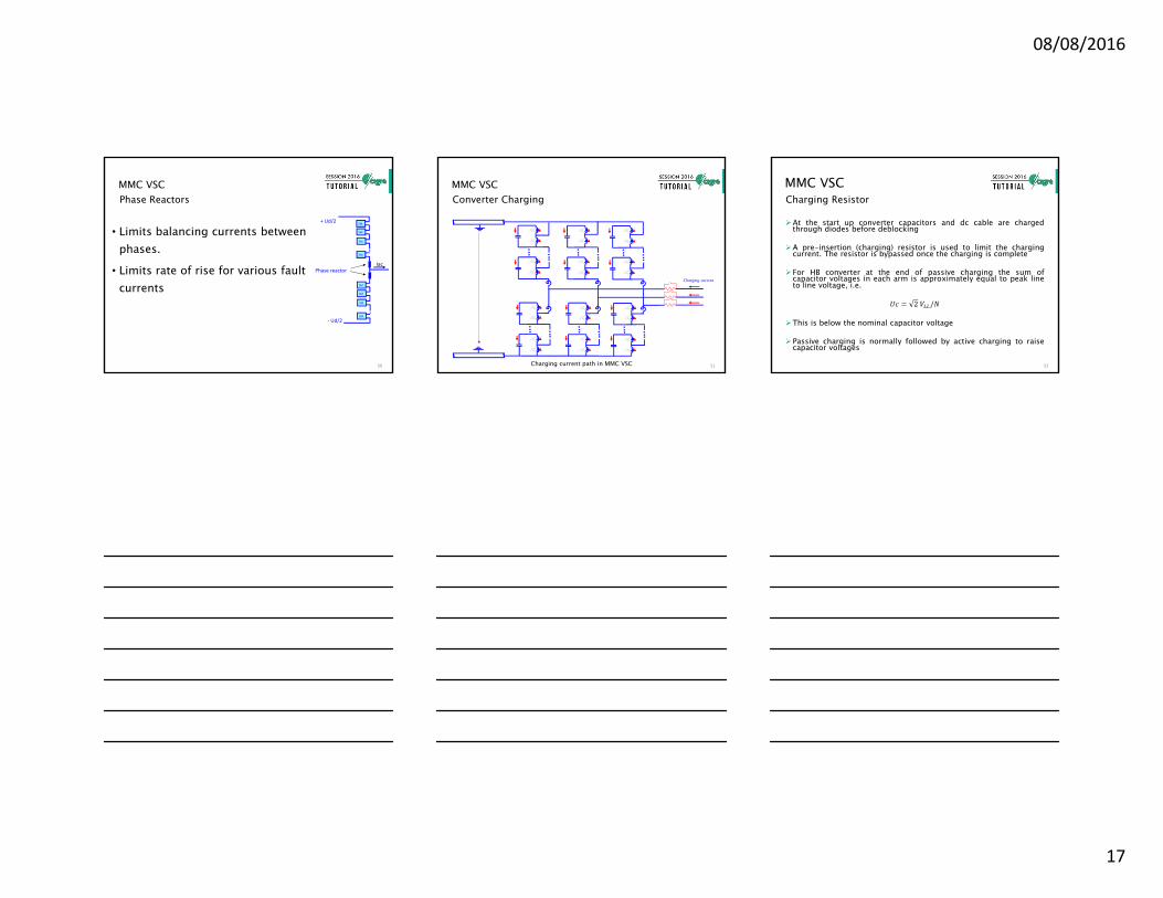
MMC VSC
• Limits balancing currents between phases.
• Limits rate of rise for various fault currents
Phase Reactors
SM
SM
SM
SM
SM
SM
SM
SM
+ Ud/2
‐ Ud/2
Phase reactorIac
50
MMC VSC
Charging current path in MMC VSC
Converter Charging
Charging current
51
MMC VSC
At the start up converter capacitors and dc cable are chargedthrough diodes before deblocking
A pre-insertion (charging) resistor is used to limit the chargingcurrent. The resistor is bypassed once the charging is complete
For HB converter at the end of passive charging the sum ofcapacitor voltages in each arm is approximately equal to peak lineto line voltage, i.e.
2 /
This is below the nominal capacitor voltage
Passive charging is normally followed by active charging to raisecapacitor voltages
Charging Resistor
52
08/08/2016
18
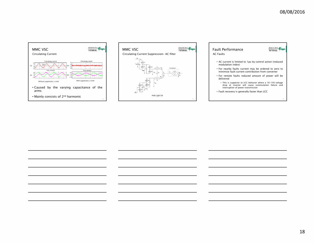
MMC VSCCirculating Current
Without suppression, L=1mH With suppression, L=1mH
• Caused by the varying capacitance of thearms
• Mainly consists of 2nd harmonic53
MMC VSCCirculating Current Suppression– AC filter
HVdc Light G4
54
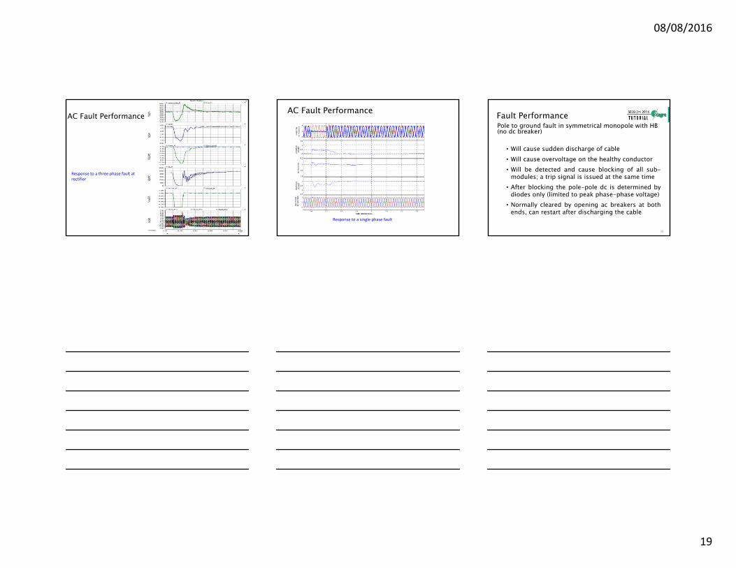
Fault Performance
• AC current is limited to 1pu by control action (reducedmodulation index)
• For nearby faults current may be ordered to zero tominimize fault current contribution from converter
• For remote faults reduced amount of power will bedelivered
• This is supperior to LCC behavior where a 10-15% voltagedrop at inverter will cause commutation failure andinterruption of power transmission
• Fault recovery is generally faster than LCC
AC Faults
55
08/08/2016
19
AC Fault Performance
Response to a three phase fault at rectifier
56
AC Fault Performance
Response to a single phase fault
Fault Performance
• Will cause sudden discharge of cable• Will cause overvoltage on the healthy conductor• Will be detected and cause blocking of all sub-
modules; a trip signal is issued at the same time• After blocking the pole-pole dc is determined by
diodes only (limited to peak phase-phase voltage)• Normally cleared by opening ac breakers at both
ends, can restart after discharging the cable
Pole to ground fault in symmetrical monopole with HB (no dc breaker)
58
08/08/2016
20
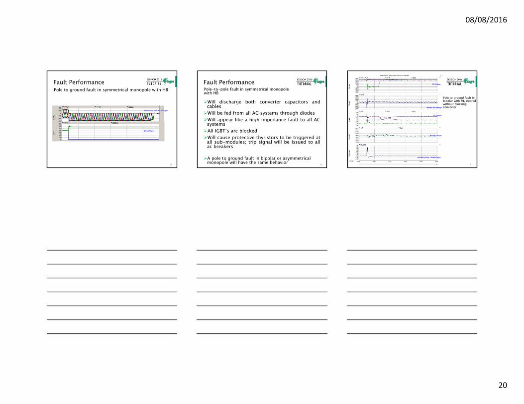
Fault PerformancePole to ground fault in symmetrical monopole with HB
Secondary side AC voltages
DC voltages
59
Fault Performance
Will discharge both converter capacitors andcablesWill be fed from all AC systems through diodesWill appear like a high impedance fault to all AC
systemsAll IGBT’s are blockedWill cause protective thyristors to be triggered at
all sub-modules; trip signal will be issued to allac breakers
A pole to ground fault in bipolar or asymmetrical monopole will have the same behavior
Pole-to-pole fault in symmetrical monopole with HB
60
Pole to ground fault in bipolar with FB, cleared without blocking converter
Ground Current ‐ South station
DC Current
DC Voltage
Neutral Bus Voltage
Reactive Power
61
08/08/2016
21
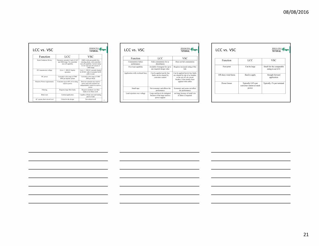
Function LCC VSCSemi-Conductor Device Thyristors currently 6 inch, 8.5 kV
and 5000 Amps. No controlled turn off capability
IGBTs with anti-parallel free wheeling diode, with controlled
turn-off capability. Current rating 4.5 kV and turn off current of
~2000 Amps.
DC transmission voltage Up to +/- 800 kV bipolar operation
Up to +/- 500 kV currently limited by HVDC cable if extruded XLPE
cable is used.
DC power Currently in the range of 7000 MW per bipolar system
Currently in the range of 1000 MW per block
Reactive Power requirements Consumes up to 60% of its rating reactive power
Does not consume any reactive power and each terminal can
independently control its reactive power.
Filtering Requires large filter banks Requires moderate size filter banks or no filters at all.
Black start Limited application Capable of black start and feeding passive loads
AC system short circuit level Critical in the design Not critical at all
LCC vs. VSC
62
Function LCC VSCCommutation failure
performanceFails commutation for ac
disturbancesDoes not fail commutation
Over load capability Available if designed for up to any required design value
Requires increased rating of the link
Application with overhead lines Can be applied and dc line faults can be cleared by
converter control
Can be applied but dc line faults are cleared by trip of ac breaker,
or the use of a dc circuit breaker. It has mostly been
applied with cables
Small taps Not economic and affects the performance
Economic and seems not affect the performance
Load rejection over voltage Large and has to be mitigated because of the large reactive
power support
not large because of small size of filters if required.
LCC vs. VSC
Function LCC VSC
Foot print Can be large Small for the comparable rating to an LCC
Off shore wind farms Hard to apply Straight forward application
Power losses Typically 0.8% per converter station at rated
power
Typically 1% per terminal
LCC vs. VSC
08/08/2016
22
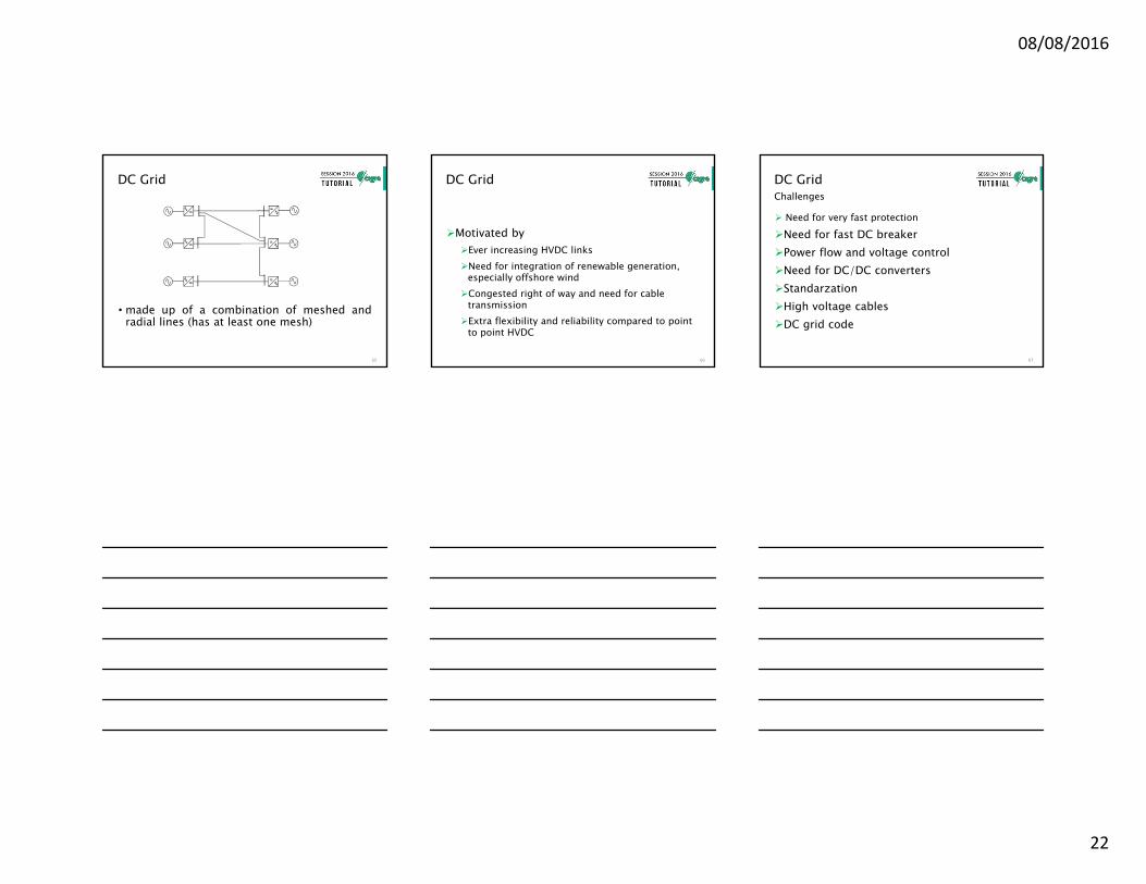
DC Grid
• made up of a combination of meshed andradial lines (has at least one mesh)
65
DC Grid
Motivated by Ever increasing HVDC linksNeed for integration of renewable generation,
especially offshore windCongested right of way and need for cable
transmissionExtra flexibility and reliability compared to point
to point HVDC
66
DC Grid
Need for very fast protection
Need for fast DC breakerPower flow and voltage controlNeed for DC/DC convertersStandarzationHigh voltage cablesDC grid code
Challenges
67
08/08/2016
23
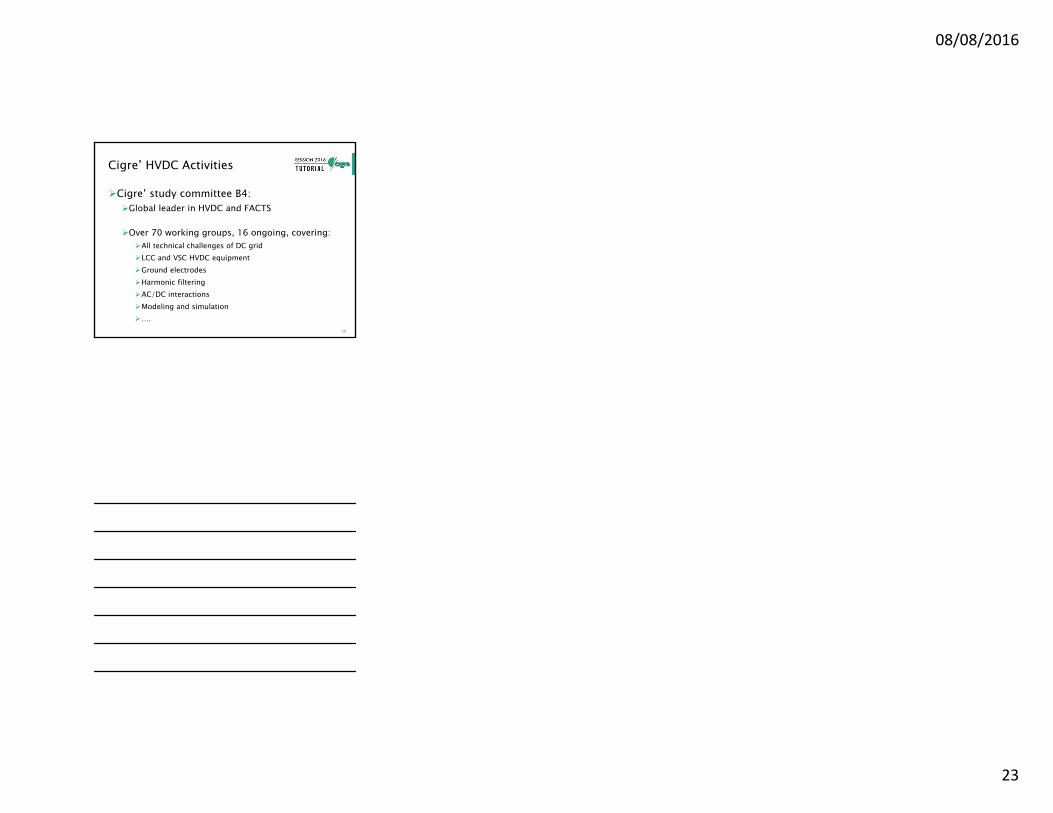
Cigre’ HVDC Activities
Cigre’ study committee B4:Global leader in HVDC and FACTS
Over 70 working groups, 16 ongoing, covering:All technical challenges of DC gridLCC and VSC HVDC equipmentGround electrodesHarmonic filteringAC/DC interactionsModeling and simulation….
68
COPYRIGHT © 2016
This tutorial has been preparedbased upon the work of CIGRE andits Working Groups. If it is used intotal or in part, proper referenceand credit should be given toCIGRE.
DISCLAIMER NOTICE
“CIGRE gives no warranty orassurance about the contents ofthis publication, nor does it acceptany responsibility, as to theaccuracy or exhaustiveness of theinformation. All implied warrantiesand conditions are excluded to themaximum extent permitted by law”.
COPYRIGHT & DISCLAIMER NOTICE