Embed Size (px)
Citation preview
Series / Parallel Hybrid VSC-LCC
for HVdc Transmission Systems
By:
Behzad Qahraman
A Thesis
Submitted to the Faculty of Graduate Studies in Partial Fulfillment
of the Requirements for the Degree of
Doctor of Philosophy
Department of Electrical and Computer Engineering
University of Manitoba
Winnipeg, Manitoba
© Copyright by Behzad Qahraman 2010

Acknowledgments
This work is carried out at the Department of Electric and Computer Engineering at the
University of Manitoba.
First of all I wish to express my deepest gratitude to Professor A. M. Golé,
NSERC Industrial Research Chair in Power System Simulation at the University of
Manitoba. He gave me the opportunity to explore the interesting field of hybrid
converters and was an excellent adviser and supporter. His support was invaluable to me
and without his encouragement and professional assistance I could never finish this
research. More than that, his sincere, friendly relationship was a great stimulus for work
and is far more honored advantage.
I would like to thank Dr. M. Mohaddes from TransGrid Solutions Inc. for his
valuable discussions and constructive suggestions. I also appreciate Professor Shaahin
Filizadeh‟s review and comments on my thesis.
The financial support for this research by Manitoba Hydro Company and by
continuing generous support from Natural Sciences and Engineering Research Council
(NSERC) of Canada is greatly appreciated.
Finally, I wish to thank Katayon, my wife, and my children, for their support and
patience during the time I worked on this thesis.
ii
Abstract
This thesis investigates the feasibility of hybrid converter based arrangements for High
Voltage direct current (HVdc) transmission systems. The conventional HVdc
transmission systems, which use Line Commutated Converter (LCC) technology, require
ac voltage and large amounts of reactive power to operate; Voltage-Sourced Converter
(VSC) based HVdc schemes, on the other hand, while maintaining most of the
advantages of LCC-based systems, have overcome a number of disadvantages inherent
to conventional LCC systems. Their ability to provide voltage support to very weak ac
networks through generating reactive power, while delivering real power, makes them an
ideal option for providing reliable power to remote locations. These converters suffer
disadvantages such as higher costs, sensitivity to dc-side faults, and smaller ratings in
comparison to conventional converters.
This research exploits a new approach and introduces a hybrid configuration of VSC
and LCC converters. The hybrid converter combines the advantages of these two
converter types, while trying to stay far from their disadvantages. The thesis investigates
and discusses the benefits of using VSC-LCC hybrid converters for HVdc transmission
systems in stations where support of ac voltage is mostly absent (very weak ac system).
It concludes that Series Hybrid Converter (SHC) configuration is a promising option for
very weak ac system applications comparing to Parallel Hybrid Converter (PHC) option.
Using simplified mathematical models and extensive effort on digital time
simulation with PSCAD / EMTDC program, the technical feasibility of implementing
SHC has been demonstrated.
iii
Table of Contents
Acknowledgments ............................................................................................................. i
Abstract ............................................................................................................................ ii
Table of ContentsList of Figures ................................................................................... iii
List of Figures ................................................................................................................. vi
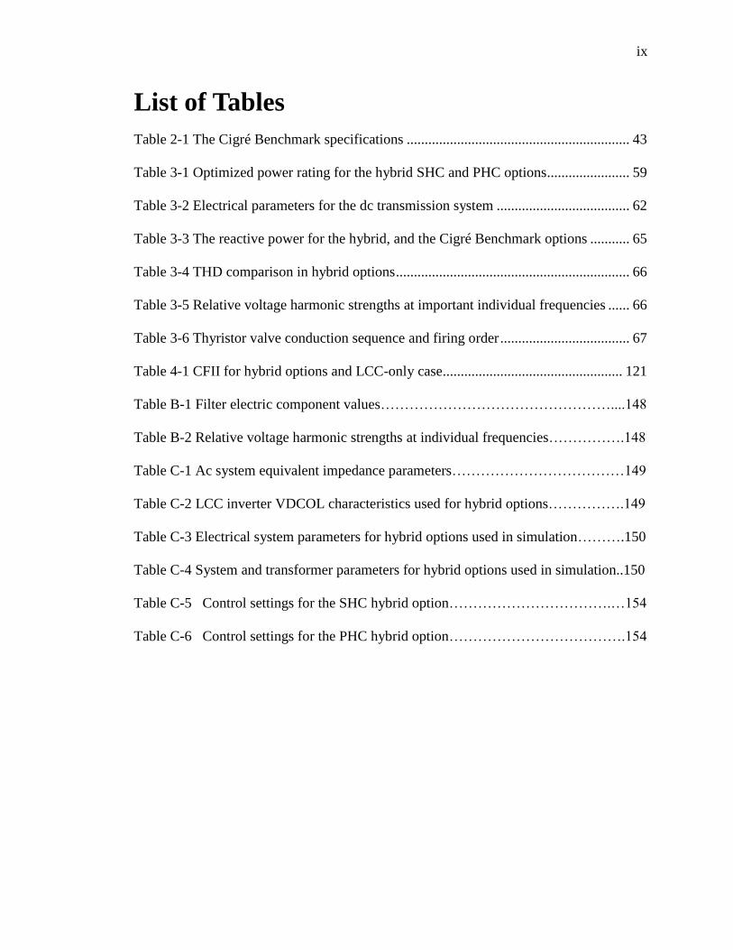
List of Tables ................................................................................................................... ix
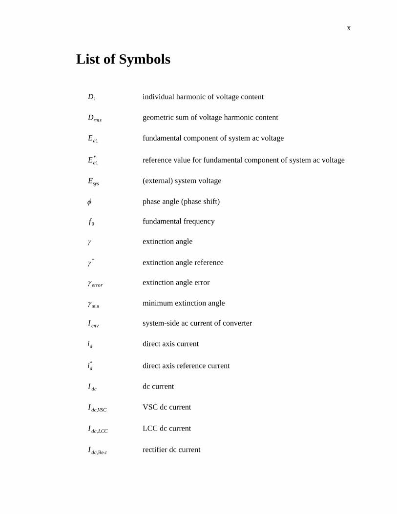
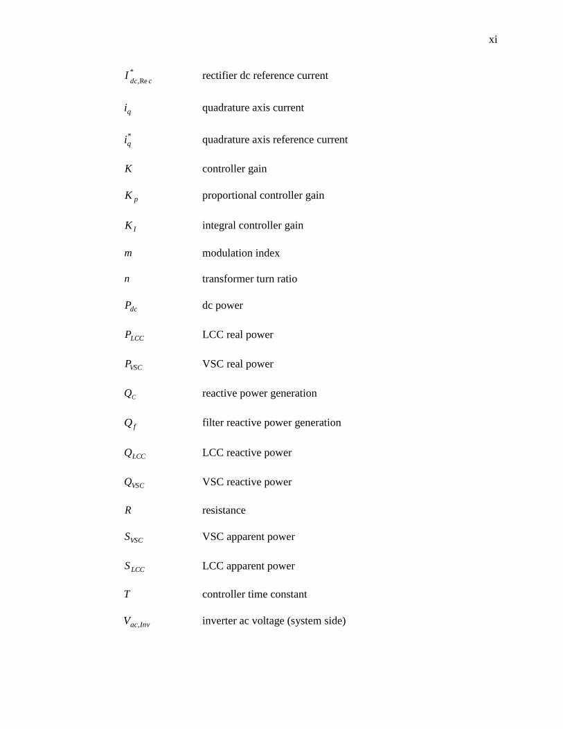
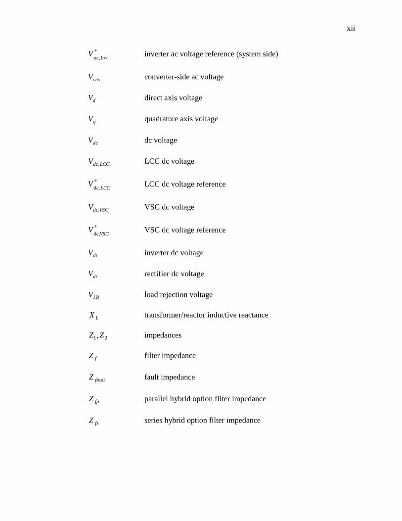
List of Symbols ................................................................................................................. x
List of Abbreviations .................................................................................................... xiii
Chapter 1: Introduction .......................................................................................... 1
1.1 Overview ............................................................................................................ 1
1.2 Ac system strength ............................................................................................. 3
1.3 Basic features of the CSC and VSC converters ................................................. 3
1.4 Line commutated versus forced commutated converters ................................... 5
1.5 What is a hybrid converter and why use it ....................................................... 10
1.6 Scope of the work............................................................................................. 12
1.7 Objectives of the work ..................................................................................... 13
1.8 Thesis outline ................................................................................................... 14
1.9 Literature review .............................................................................................. 15
Chapter 2: LCC vs. VSC Based HVdc Transmission Systems .......................... 22
2.1 Introduction ...................................................................................................... 22
2.2 HVdc system requirements and characteristics................................................ 22
2.3 HVdc system components and their representation ......................................... 23
2.4 LCC-HVdc systems and their basic principles ................................................ 26
2.5 VSC-HVdc systems and their basic principles ................................................ 29
2.6 Converter arrangements ................................................................................... 35
iv
2.7 HVdc controls .................................................................................................. 36
2.8 Basic protection requirements .......................................................................... 40
2.9 Benchmark for HVdc system simulation studies ............................................. 42
Chapter 3: Hybrid HVdc Configurations ........................................................... 44
3.1 Introduction ...................................................................................................... 44
3.2 Hybrid converter HVdc transmission systems ................................................. 44
3.3 Hybrid converter arrangements ........................................................................ 45
3.4 Main components of HVdc electrical system .................................................. 49
3.5 Hybrid system general description ................................................................... 53
3.6 Hybrid design philosophy ................................................................................ 55
3.7 VSC capacitor size selection ............................................................................ 59
3.8 Control objectives in hybrid design ................................................................. 60
3.9 Hybrid system harmonics and filters ............................................................... 62
3.10 Hybrid level converter controls ........................................................................ 66
3.11 Hybrid converter control strategy .................................................................... 70
3.12 Decoupled vs. direct control of VSC converters .............................................. 70
3.13 Implemented VSC control for hybrid options .................................................. 73
3.14 Circuit control strategy for the SHC converter ................................................ 75
3.15 Circuit control strategy for PHC converter ...................................................... 79
Chapter 4: Hybrid Converter Transmission System Performance .................. 83
4.1 Introduction ...................................................................................................... 83
4.2 Method / tools for system study ....................................................................... 86
4.3 Hybrid system development steps .................................................................... 88
4.4 Parameter tuning .............................................................................................. 89
4.5 System start-up procedure ................................................................................ 92
4.6 Control considerations in hybrid inverters ....................................................... 93
4.7 Smooth transition between the controller‟s outputs ......................................... 96
v
4.8 Analysis of hybrid system performance ........................................................... 97
4.9 Intrinsic drawback of parallel hybrid converters (PHC) ................................ 118
4.10 Hybrid converter commutation failure performance...................................... 121
4.11 VSC converters overcurrent protection .......................................................... 122
Chapter 5: Concluding Remarks ....................................................................... 123
5.1 Introduction .................................................................................................... 123
5.2 Hybrid converter applications ........................................................................ 124
5.3 Highlight of the performed tasks.................................................................... 126
5.4 Conclusions and findings of the research ...................................................... 127
5.5 Main contributions of the thesis ..................................................................... 130
5.6 Further recommendations for future work ..................................................... 131
References: ................................................................................................................... 133
Appendix A: Hybrid Electrical System Design .................................................... 140
A.1 Introduction ....................................................................................................... 140
A.2 Determining transformer power rating for the hybrid options ......................... 140
A.3 Determining transformer rating for rectifier converter ..................................... 141
A.4 Voltage and current calculations for hybrid options ......................................... 142
Appendix B: Ac Filters ........................................................................................... 146
Appendix C: Electrical and Controller Parameters ............................................ 149
C.1 Ac system equivalent impedance ...................................................................... 149
C.2 VDCOL characteristics ..................................................................................... 149
C.3 System and electrical parameters ...................................................................... 150
C.4 SHC hybrid inverter and LCC rectifier control diagram .................................. 151
C.5 The SHC converter parameters ......................................................................... 152
C.6 PHC hybrid inverter and LCC rectifier control diagram .................................. 153
C.7 The PHC converter parameters ......................................................................... 154
Appendix D: PSCAD Electrical System Map ....................................................... 155
vi
List of Figures
Figure 1.1 Schematics for (a) current-sourced converter, (b) voltage-sourced converter . 3
Figure 1.2 Line commutated CSC schematic using thyristor valves ................................. 6
Figure 1.3 Forced-commutated current-sourced converter using GTO valves ................. 8
Figure 1.4 Forced commutated VSC using IGBT valves .................................................. 8
Figure 2.1 Thyristor symbol and its I-V characteristics .................................................. 24
Figure 2.2 GTO symbol and its I-V characteristics ......................................................... 25
Figure 2.3 IGBT symbol and its I-V characteristics ........................................................ 26
Figure 2.4 A simplified HVdc system with line commutated CSC at inverter side ........ 27
Figure 2.5 A simplified HVdc system with forced commutated VSC converter ............ 30
Figure 2.6 (a) Principle of VSC operation, and (b) generated ac voltage waveforms ..... 31
Figure 2.7 (a) Reactive, and (b) active power generation in VSC converters ................. 32
Figure 2.8 PWM basis ..................................................................................................... 34
Figure 2.9 LCC control features ...................................................................................... 38
Figure 2.10 The Cigré Benchmark model presentation ................................................... 42
Figure 3.1 A simplified SHC-HVdc transmission system ............................................... 46
Figure 3.2 A simplified PHC-HVdc transmission system ............................................... 48
Figure 3.3 RL equivalent network ................................................................................... 51
Figure 3.4 General hybrid converter based HVdc transmission system .......................... 54
Figure 3.5 Simplified dc overhead transmission line equivalent ..................................... 61
Figure 3.6 Decoupled-based VSC control ....................................................................... 71
Figure 3.7 Direct method for VSC control ...................................................................... 72
Figure 3.8 VSC converter controls for the SHC option................................................... 74
vii
Figure 3.9 VSC converter controls for the PHC option................................................... 75
Figure 3.10 LCC inverter controls for the SHC option ................................................... 78
Figure 3.11 Rectifier LCC controls for SHC option........................................................ 79
Figure 3.12 LCC inverter controls for the PHC option ................................................... 81
Figure 3.13 LCC controls for rectifier in PHC option ..................................................... 82
Figure 4.1 Block diagram for modified VDCOL ............................................................ 94
Figure 4.2 Adjusting the sensitivity of γ-controller ......................................................... 95
Figure 4.3 LCC hybrid inverter control transition modes ............................................... 96
Figure 4.4 Smooth control transition mechanism for (a) SHC and (b) PHC options ...... 96
Figure 4.5 Small dynamic disturbance response to step change in power order ........... 100
Figure 4.6 Response to step change in rectifier dc current order .................................. 102
Figure 4.7 Step change in ac system short circuit ratio (SCR) ...................................... 103
Figure 4.8 Overvoltage following an inverter load rejection ........................................ 106
Figure 4.9 Three-phase inverter-side ac fault ................................................................ 108
Figure 4.10 Three-phase inverter-side remote ac fault .................................................. 110
Figure 4.11 Single phase ac inverter-side close-in fault ................................................ 111
Figure 4.12 Three phase ac rectifier-side close-in fault ................................................ 113
Figure 4.13 Three phase rectifier-side ac remote fault .................................................. 115
Figure 4.14 Dc fault at inverter dc terminal .................................................................. 117
Figure 4.15 Circulating current in PHC option during an ac inverter-side fault ........... 118
Figure 4.16 Circulating current in PHC option during a dc fault .................................. 119
Figure 4.17 Circulating current between LCC and VSC converters in PHC option ..... 120
Figure B-1 Filter frequency response for the SHC / PHC hybrid options…………..…146
viii
Figure B-2 Normalized filter frequency response for the SHC/PHC hybrid options….147
Figure C-1 SHC hybrid inverter and LCC rectifier control diagram……………….... 151
Figure C-2 PHC hybrid inverter and LCC rectifier control diagram…………………. 153
Figure D-1 PSCAD electrical layout for the SHC option……………………………. .155
Figure D-2 PSCAD electrical layout for the PHC option……………………………. .155
Figure D-3 PSCAD control logic diagram for IGBT overcurrent control……….… …154
ix
List of Tables
Table 2-1 The Cigré Benchmark specifications .............................................................. 43
Table 3-1 Optimized power rating for the hybrid SHC and PHC options ....................... 59
Table 3-2 Electrical parameters for the dc transmission system ..................................... 62
Table 3-3 The reactive power for the hybrid, and the Cigré Benchmark options ........... 65
Table 3-4 THD comparison in hybrid options ................................................................. 66
Table 3-5 Relative voltage harmonic strengths at important individual frequencies ...... 66
Table 3-6 Thyristor valve conduction sequence and firing order .................................... 67
Table 4-1 CFII for hybrid options and LCC-only case.................................................. 121
Table B-1 Filter electric component values…………………………………………....148
Table B-2 Relative voltage harmonic strengths at individual frequencies…………….148
Table C-1 Ac system equivalent impedance parameters………………………………149
Table C-2 LCC inverter VDCOL characteristics used for hybrid options…………….149
Table C-3 Electrical system parameters for hybrid options used in simulation……….150
Table C-4 System and transformer parameters for hybrid options used in simulation..150
Table C-5 Control settings for the SHC hybrid option…………………………….…154
Table C-6 Control settings for the PHC hybrid option……………………………….154
x
List of Symbols
iD individual harmonic of voltage content
rmsD geometric sum of voltage harmonic content
1aE fundamental component of system ac voltage
*1aE reference value for fundamental component of system ac voltage
sysE (external) system voltage
phase angle (phase shift)
0f fundamental frequency
extinction angle
* extinction angle reference
error extinction angle error
min minimum extinction angle
cnvI system-side ac current of converter
di direct axis current
*di direct axis reference current
dcI dc current
VSCdcI , VSC dc current
LCCdcI , LCC dc current
cdcI Re, rectifier dc current
xi
*
Re, cdcI rectifier dc reference current
qi quadrature axis current
*qi quadrature axis reference current
K controller gain
pK proportional controller gain
IK integral controller gain
m modulation index
n transformer turn ratio
dcP dc power
LCCP LCC real power
VSCP VSC real power
CQ reactive power generation
fQ filter reactive power generation
LCCQ LCC reactive power
VSCQ VSC reactive power
R resistance
VSCS VSC apparent power
LCCS LCC apparent power
T controller time constant
InvacV , inverter ac voltage (system side)
xii
*
,InvacV inverter ac voltage reference (system side)
cnvV converter-side ac voltage
dV direct axis voltage
qV quadrature axis voltage
dcV dc voltage
LCCdcV , LCC dc voltage
*
,LCCdcV LCC dc voltage reference
VSCdcV , VSC dc voltage
*
,VSCdcV VSC dc voltage reference
diV inverter dc voltage
drV rectifier dc voltage
LRV load rejection voltage
LX transformer/reactor inductive reactance
21,ZZ impedances
fZ filter impedance
faultZ fault impedance
fpZ parallel hybrid option filter impedance
fsZ series hybrid option filter impedance
xiii
List of Abbreviations
AOI Inverter Alpha Order
AOR Rectifier Alpha Order
CCC Capacitor Commutated Converter
CF Commutation Failure
CFII Commutation Failure Immunity Index
CSC Current-Sourced Converter
EMTP Electro Magnetic Transient Program
ESCR Effective Short Circuit Ratio
FCC Forced Commutated Converter
GTO Gate Turn Off Transistor
HVdc High Voltage Direct Current
IGBT Insulated Gate Bipolar Transistor
LCC Line-Commutated Converter
MAP Maximum Available Power
MI Modulation Index
PCC Point of Common Coupling
PHC Parallel Hybrid Converter
PI Proportional Integral
PLL Phase Locked Loop
PORD Power Order
PS Phase Shift
PSCAD Power System Computer Aided Design
xiv
p.u. Per-Unit
PWM Pulse Width Modulation
rms Root Mean Square
SCR Short Circuit Ratio
STATCOM Static Compensator
SHC Series Hybrid Converter
SHEM Selective Harmonic Elimination Method
SPWM Sinusoidal Pulse Width Modulation
TCSC Thyristor Controlled Series Capacitor
THD Total Harmonic Distortion
VDCOL Voltage Dependent Current Order Limiter
VSC Voltage-Sourced Converter
Chapter 1: Introduction
1.1 Overview
High Voltage Direct Current (HVdc) technology is a high-power electronics
technology used in electric power systems for bulk power transmission. Reduced power
losses, reduced line costs, increased system stability, better control of power flow and
fast development of the semi-conductor technology have made the HVdc systems more
competitive with ac systems [1]. HVdc is an efficient and flexible method to transmit
large amounts of electrical power over long distances by overhead transmission lines or
underground / submarine cables. It is also used to interconnect separate power systems,
where conventional Alternating Current (ac) connections cannot be used. These systems
are being widely used today.
The fundamental process that occurs in an HVdc system is the conversion of
electrical current from ac to dc (rectifying) at the sending end, and from dc to ac
(inverting) at the receiving end. Converters can be classified based on the method used
for commutation, which might be of natural (line, or self), or of forced type. Accordingly
they are referred to as Line Commutated Converters (LCC) and Forced Commutated
Converters (FCC), respectively. They may also be classified based on how they appear
from ac system terminals‟ point of view, which might be a current- or a voltage-sourced,
hence the names Current-Sourced Converters (CSC), and Voltage-Sourced Converters
(VSC).
So far, the majority of existing HVdc schemes are built with converter stations with
conventional LCC converters. These converters have the advantage of being robust and
2
are able to rapidly control the direct current, e.g. at faults on the dc side. In these
converters, the ac current always lags behind the line voltage, due to the firing delay on
the thyristors. This means that they always need to consume reactive power, which is a
disadvantage (Section 2.4).
The short-comings of the LCC converters for supplying weak ac systems have made
it attractive to investigate the possibility of using the forced commutated type converter
which are based on the gate-turn-off thyristors (GTOs) or Insulated Gate Bipolar
Transistors (IGBTs) (Sections 2.3.1.2 and 2.3.1.3). The commutation in this type of
converter is performed independently of the line voltage, which makes it possible to
control the converters at the two ends of the dc line such that they both consume and
generate reactive power independent of the generated active power. This implies that
very weak ac systems and even systems with local generation can be supplied with
power using forced commutated converters.
However, these converters are more expensive than the line commutated converters
and there is a challenge to stack them in series to generate the required voltage. The VSC
converter is most effective at the inverter side as it can provide reactive power and
support ac terminal voltage. In this research, only the inverter-hybrid configuration, in
the form of series and parallel connection of one LCC and one VSC converter, has been
studied in detail and the rectifier is of a conventional LCC type. The performance of the
proposed hybrid configurations are compared with conventional arrangement of only
LCC type converters. The LCC-type converter used for comparison is the First Cigré
Benchmark model (used as the Cigré Benchmark in this thesis) system, as is explained in
section 2.9.1
3
1.2 Ac system strength
The strength of an ac network at fundamental frequency is measured in terms of its
Short Circuit Ratio (SCR), which is defined as the ratio of the short circuit MVA of the
ac system at the ac busbar with the dc blocked, to the rated dc power of that busbar [2].
This ratio is equivalent to the system Thevenin admittance expressed in per unit with the
rated dc power as the MVA base and rated ac voltage as the voltage base. Ac systems
connected to converters, have an equivalent ac-network that has to be included in the
system representation. This ac equivalent is inversely proportional to the SCR. A
network with an SCR smaller than 2 is considered to be a very weak system [2]. The
term “weak system” used in this report has the meaning of “electrically weak”, i.e. the ac
system with equivalent voltage source behind high equivalent impedance [3].
1.3 Basic features of the CSC and VSC converters
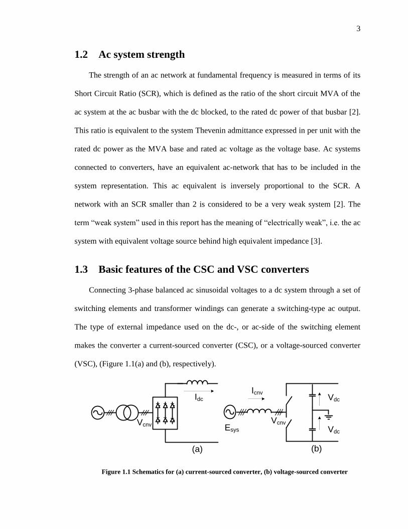
Connecting 3-phase balanced ac sinusoidal voltages to a dc system through a set of
switching elements and transformer windings can generate a switching-type ac output.
The type of external impedance used on the dc-, or ac-side of the switching element
makes the converter a current-sourced converter (CSC), or a voltage-sourced converter
(VSC), (Figure 1.1(a) and (b), respectively).
Idc
Vdc
Vcnv
Icnv
(a) (b)
Vdc
Vcnv Esys
Figure 1.1 Schematics for (a) current-sourced converter, (b) voltage-sourced converter
4
1.3.1 The current-sourced converter
It can be shown [1] that the dc voltage in current-sourced converters (CSC) is
proportional to the ac-side voltage, multiplied by the cosine of the angle between the
fundamental frequency component of the alternating phase current and ac-phase voltage.
This angle may be controlled by controlling the switching time.
The ac current has a magnitude proportional to the dc current as it is created directly
from the dc current by switching, therefore it has harmonics, which need filtering. On
the dc side, it acts as a constant current source ( dcI ) and needs an inductor as its energy
storing device; it requires dc filters to operate properly (Figure 1.1(a)). It provides
inherent fault current limiting features. The semiconductors used can be of the line, or
forced commutated type and switch at line frequency, which brings low switching losses
[5]. In CSCs the polarity of the dc voltage would change whenever the angle goes
beyond 90 degrees (it changes with dc power flow), but the polarity of dc current cannot
change. The valves are commanded to turn on at the appropriate instant by controlling
the angle at which the firing pulses are issued. One major advantage of these converters
is the possibility of dc voltage control, by controlling the angle at which the firing pulse
is issued. The dc fault current can be limited by control action.
1.3.2 The voltage-sourced converter
It can be shown [6] that the dc current in voltage-sourced converter is proportional
to the ac-side voltage, multiplied by the sine of the phase displacement angle between
the fundamental frequency components of the converter output voltage and the network
alternating voltage.
5
The ac voltage is proportional to the capacitor voltage on the dc side as it is created
directly from the dc voltage by switching (Figure 1.1(b)). It also generates harmonics,
but the transformer inductance, or an external inductance, helps to filter out the
generated harmonics. Some filtering, mostly at higher order components, is usually
needed. A VSC does not need reactive power supply. On the dc side it acts as a constant
voltage source and needs a capacitor to maintain the voltage constant. It encounters
difficulty for dc line side faults because of discharging the capacitor into the fault. It uses
self-commutated semiconductors, and switches at high frequencies, which brings higher
switching losses [5]. In VSCs the dc current polarity can be altered by reversing the
polarity of the mentioned angle (it changes with the dc power flow), but the polarity of
the dc voltage cannot change. It may be concluded that the active power flow can be
changed by changing the polarity of the dc current. Because of this bi-directionality, the
switches must be capable of conducting current in both directions. The dc fault current
cannot be limited by control action because of the reverse diodes used in the converter.
Here a dc breaker is needed to interrupt the dc fault current.
1.4 Line commutated versus forced commutated converters
The switching circuit, which performs the conversion from dc to ac or ac to dc, can
rely on the ac line voltage (which is called Line Commutated Converter, LCC), or not
(which is called Forced Commutated Converter, FCC).
1.4.1 Line commutated converters
Line commutated converters rely on the line voltage for performing the
commutation of the current. The switching component of LCC converters uses
6
thyristors, which are only capable of conducting current in one direction (Section
2.3.1.1). They start to conduct current when a positive voltage is applied across the
valve and a triggering pulse is applied across the gate. The requirement of the positive
voltage results in that the ac voltage will always lead the ac current in phase. A
consequence of this is that the LCC always absorbs reactive power both in rectifier and
inverter, which at rated power amounts to around 60% of their real power rating. During
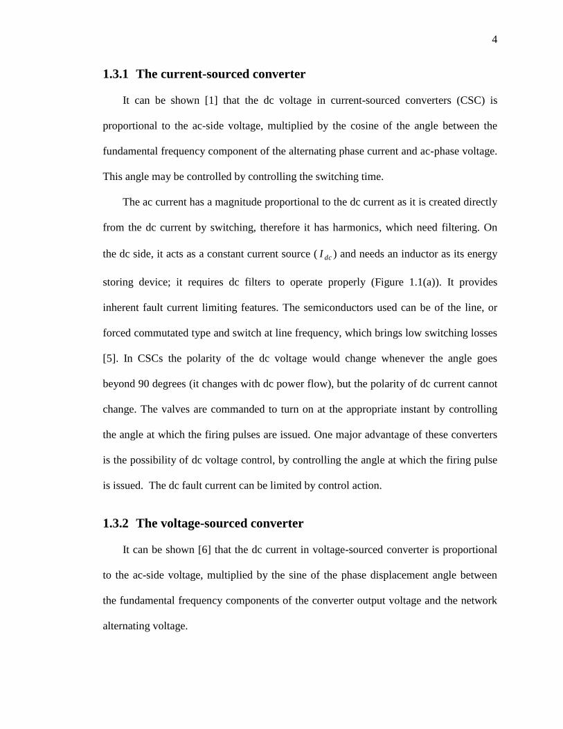
its normal operation, LCC will switch the current periodically from one thyristor valve
to the other, in a specified sequence [4]. Failing in a current transfer would cause
commutation failure (CF), which probably will cause a (permanent) short circuit
between two phases. Figure 1.2. Shows a simple schematic for a line commutated CSC.
Idc
XL
DC line
Esys
Figure 1.2 Line commutated CSC schematic using thyristor valves
Another type of line commutated converter uses anti-parallel connection of diodes
and thyristors as switching elements. In this converter only half of the converters are
controllable, which makes dc line fault recovery more difficult. The harmonic content is
also higher. Due to these facts such converters are not practically employed [7].
Depending on the voltage / power rating under consideration, the thyristors will be
arranged in series, parallel, or series/parallel configurations. Due to their nature, these
converters need large external reactive power support [4]; they are sensitive to ac
7
terminal voltage changes and need large amounts of filtering [3]. Thyristor-based LCC
converters cannot work under very low SCR conditions without appropriate dynamic
voltage control and support of devices such as static or synchronous VAR compensators
[8], [9], [10]. The common practice is that even with dynamic voltage support, part of
the needed reactive power will be supplied using static VAR generators, in the form of
dedicated capacitors / filter capacitors [4].
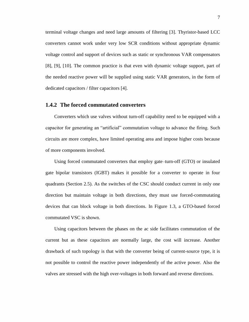
1.4.2 The forced commutated converters
Converters which use valves without turn-off capability need to be equipped with a
capacitor for generating an “artificial” commutation voltage to advance the firing. Such
circuits are more complex, have limited operating area and impose higher costs because
of more components involved.
Using forced commutated converters that employ gate–turn-off (GTO) or insulated
gate bipolar transistors (IGBT) makes it possible for a converter to operate in four
quadrants (Section 2.5). As the switches of the CSC should conduct current in only one
direction but maintain voltage in both directions, they must use forced-commutating
devices that can block voltage in both directions. In Figure 1.3, a GTO-based forced
commutated VSC is shown.
Using capacitors between the phases on the ac side facilitates commutation of the
current but as these capacitors are normally large, the cost will increase. Another
drawback of such topology is that with the converter being of current-source type, it is
not possible to control the reactive power independently of the active power. Also the
valves are stressed with the high over-voltages in both forward and reverse directions.
8
Idc
XL
DC line
Esys
Figure 1.3 Forced-commutated current-sourced converter using GTO valves
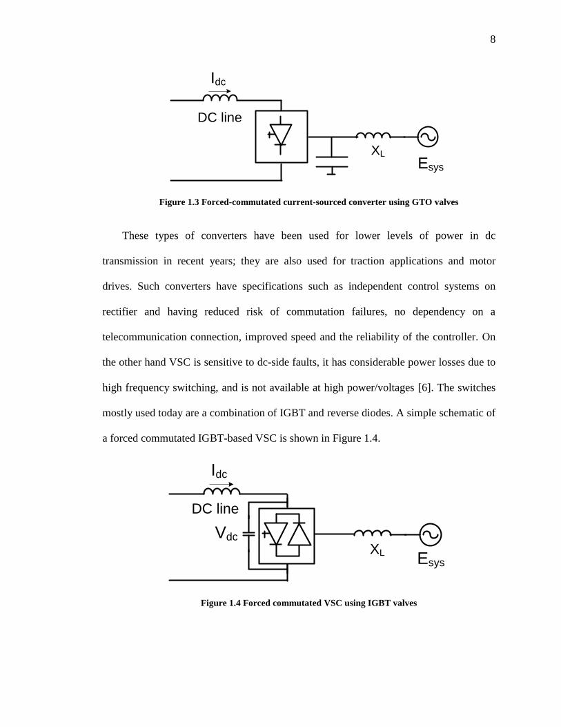
These types of converters have been used for lower levels of power in dc
transmission in recent years; they are also used for traction applications and motor
drives. Such converters have specifications such as independent control systems on
rectifier and having reduced risk of commutation failures, no dependency on a
telecommunication connection, improved speed and the reliability of the controller. On
the other hand VSC is sensitive to dc-side faults, it has considerable power losses due to
high frequency switching, and is not available at high power/voltages [6]. The switches
mostly used today are a combination of IGBT and reverse diodes. A simple schematic of
a forced commutated IGBT-based VSC is shown in Figure 1.4.
Idc
XL
DC line
Esys
Vdc
Figure 1.4 Forced commutated VSC using IGBT valves
9
1.4.3 Advantages and disadvantages of LCC and VSC converters
Line commutated converters have been the most common option for HVdc
applications. They are inexpensive and commercially available in higher ratings. Also by
reversing the voltage polarity of these converters, the direction of power flow can be
changed. For some applications such as cable transmission and multi-terminal systems
connected in parallel on the dc-side, in which operation with a constant voltage is
desirable, this feature of LCC is a disadvantage.
In LCC converters, the ac current always lags the line voltage, due to the firing
delay on the thyristors. This means that they always need to consume reactive power,
which is a disadvantage. This reactive power must be provided through var generating
devices connected to the ac work. If such converters supply a very weak electrical
system, severe problems might develop. One consequence of connection to weak ac
networks is that because such converters rely on the line voltage for commutation, if a
major disturbance happens in the ac voltage, it might cause repeated commutation
failures.
On the other hand, using forced-commutated converters and applying pulse width
modulation (PWM), it is possible to control the active and reactive power both
continuously and independently (Section 2.5). Such converters are capable of both
generating and absorbing reactive power. Another advantage for these converters is that
there is not a danger of commutation failure. Because of this, forced commutated VSCs
are less sensitive to ac voltage variations/disturbances. Such converters are capable of
controlling the frequency of the ac system, the active power and the ac system voltage.
Also because the direction of the real power flow can be reversed by changing the
10
direction of the direct current, the VSC-based converters can be used for cable
transmission system, which might need a rigid direct voltage.
One major disadvantage of VSC converters is that a fault on the dc-side will
generate high over-current which cannot be limited using system controls and lowering
the dc voltage level. Other disadvantages are high losses, their high cost and their
general unavailability for ratings above 500 MW.
1.5 What is a hybrid converter and why use it
This thesis introduces the concept of a hybrid converter. Hybrid converter is a
converter that can appear with either series, or parallel arrangement of LCC, and VSC
converters. LCC is the building block of commonly-used HVdc schemes and works well
in strong ac systems. However in weak ac systems it demonstrate very slow recovery
rate after fault, and sometimes it may not recover at all and require converter blocking
and restarting. Under very weak ac system conditions, the ac system may not be able to
attain a steady state operating point at all. Understanding that each of the LCC / VSC
converter systems has their own points of strength/weakness, there is the possibility of
assembling a composite converter system based on these two types of converters that
possesses the most of advantages of these two kinds of converters, while minimizing the
disadvantages of each.
Hybrid converters may have different structures and have their own limitations. At
the converter level, different hybrid configurations such as series and/or parallel
combination of LCC and VSCs might be constructed. Other more complicated
configurations for hybrid converter HVdc transmission systems are also possible but
these configurations come with more complex circuits/controls and higher expenses,
11
which makes their technical or financial justifications difficult. In this thesis two
separate configurations of series and parallel hybrid converters, each consisting of one
current, and one voltage sourced converter has been studied in detail. Out of these two
the series hybrid option case was found to be promising. More details are given in
Chapter 3.
1.5.1 The benefits of hybrid converters
An ideal HVdc converter should permit operation at full power range at any desired
power factor including import/export of reactive power, eliminate commutation failure
issues in severe faults (if possible), causing no significant amount of harmonic, and have
low losses. Hybrid HVdc, which employs conventional and newer HVdc technology
together, is a move in this direction. Using a well-designed “hybrid” converter, some of
the weaknesses of the LCCs will be overcome by VSC characteristics. These include:
(i) the need for external reactive resources will be eliminated; (ii) a large part of filtration
would be un-necessary; (iii) stronger inverter voltage support will be provided; (iv) real
and reactive parts still may be controlled independently to a good extent (though it will
not be necessary to control the reactive power any more), and (v) the terminal voltage
will be controlled.
At the same time some of the weaknesses of the VSC will be improved by
conventional HVdc system, including lower rating of VSC will be compensated using
higher assigned share of power to LCC; less switching losses because of lower power
share of VSC converter.
12
1.6 Scope of the work
In this report the feasibility of employing two configurations of VSC-LCC hybrid-
converter HVdc transmission systems connected to a very weak ac system are studied
and the benefits expected from employing such topologies in comparison to a LCC-only,
or to a VSC-only based HVdc transmission system are stressed. The overall hybrid
systems‟ behavior during start-up, steady-state, and following small and large dynamic
changes has been studied closely.
To fully investigate the behavior and performance of the proposed hybrid HVdc
transmission systems a coherent and exact mathematical model of both of its constituent
converters, namely the LCC and VSC converters, is needed. In fact the complexity of the
complete converter system and extensiveness of the integrated model prevents one from
mathematically analyzing the complete HVdc system. The difficulties and complexities
associated with such a model may be summarized as follows:
Extensiveness of the system,
Discontinuous and non-linear nature of signal transfer through converters,
Frequency conversion through ac-dc converters,
Complexity of interactions between ac and dc variables,
If performing an exact mathematical-based analysis is not possible, a simulation-based
method can be used instead [11]; also from an engineering point of view, more familiar
physical results could be expected from time domain simulations. A number of the
expected advantages from simulation-based studies are:
Ability to reproduce system performance with highest realistic degree of
complexity that is desired,
13
Investigating system fault modes and predicting the important parameters such as
over-voltage and over-current stresses on energy storage elements and also on
switching elements at system, and at component-level,
Having a “visual image” of system behavior under different working conditions,
Having a realistic estimate on recovery time for an HVdc system, following
disturbances with different types and severities,
Providing the basis for protection requirements in a real HVdc system.
The PSCAD / EMTDC software [12] was selected for simulating the system and
studying its behavior, as this tool is particularly suited for modelling of power
electronic-based electrical networks. The results obtained from simulation will be
presented in Chapter 4.
1.7 Objectives of the work
The objectives of the research are summarized as:
Introducing the series and parallel hybrid configurations at the converter-level
and assessing their strengths/weaknesses in an HVdc transmission system;
Analyzing and evaluating the series and parallel hybrid converter behavior
following small and large dynamic changes in the electrical system;
Examining the idea of using series and parallel hybrid converters in a very
low SCR system;
Optimally designing and simulating the series and parallel hybrid converters
Performing detailed hybrid system performance comparison with an LCC-only
(conventional) HVdc;
Suggesting and discussing the series and parallel hybrid converters‟ applications.
14
The thesis concludes that the SHC configuration is a promising option for providing
real power to a very weak ac electrical network, while adjusting the terminal voltage at
specified limits. It also concludes that the PHC option is not a good candidate for
working under very low short circuit ratio conditions and does not demonstrate an
overall good dynamic performance. It also suffers from an intrinsic drawback, to be
discussed later (Section 4.9).
1.8 Thesis outline
Following the introduction given in this chapter, the rest of the thesis is organized as
follows.
Chapter 2 presents the basic operational principles and control strategies of LCC-
HVdc, and VSC-HVdc systems, in parallel.
In Chapter 3, the hybrid concept is detailed and different hybrid configurations at
system and at converter level are covered. A series, and a parallel hybrid converter
HVdc system will be designed and its details will be worked out. The control methods
are also elaborated.
In Chapter 4 the results of detailed digital simulation of the hybrid system using
PSCAD/EMTDC simulator is presented. The system steady-state and dynamic behavior
of the system will also be discussed.
In Chapter 5 the hybrid converter‟s applications and the highlights of performed
tasks is discussed. Then conclusions obtained from the research and contributions of the
work are presented. Some suggestion/ recommendations for continuing the work are also
offered.
15
A list of references will be presented afterwards and Appendices will provide more
detailed information regarding system design and some of its numerical figures and
parameters.
1.9 Literature review
Building blocks of HVdc converters usually use line-, or forced commutated type of
semiconductors [13].
Thyristor-based (LCC) HVdc transmission systems have advantages over HVac
systems and it validates their common usage around the world [14], such as: ability to
work between non-synchronous ac systems, carrying more power per conductor, being
more economical at high power / long distances and less corona losses [15], and having
good reliability [16].
On the other hand they have disadvantages such as need for large reactive power
and filtration [4]; experiencing difficulties in working with weak ac systems at normal
conditions, such as commutation failure [2], slow fault recovery, high over-voltage
following load rejection [3], second harmonic resonance [17], [18], [19], voltage/power
instability problems [19]-[20], inefficient real power modulation to control power system
dynamic [21].
Direct current transmission utilizing LCC converters is not a new concept and
because of the large number of HVdc transmission systems of this type; they have well
established basis in different aspects such as modeling, control, protection and standards
[1],[4]-[5]. Development of the Cigré Benchmark model [22] is an important step in
CSC-HVdc modeling. Despite the maturity of these converters, there are categories with
16
on-going research subjects such as modeling and control for different types of HVdc
transmission systems, based on conventional or hybrid converters.
The main operating problems with the conventional HVdc systems connected to
weak ac systems are the high-magnitude ac voltage oscillations and the difficulty in
recovery from disturbances [2], [9] and [23].
The ability of operating these type of converters under very weak SCRs is highly
questionable [3], [8]. Modifications on standard control methods have also been
proposed that work for very low SCRs but fail for SCRs as low as one [24]. The
dynamic instabilities caused by the weak receiving ac systems are described in [25]. The
dynamic performance of a STATCOM, making emphasis on voltage stability, over
voltages and post fault recovery for a specific system of SCR = 1.5 offers the best and
fastest results in comparison to isolated solutions using dynamic var generator
equipments such as synchronous condensers and static VAR compensators [9], [10] and
[26].
Theoretically, VSC-HVdc systems using forced commutating devices are not a new
concept either [27]. These systems use devices such as IGBT/GTO semiconductors [28]-
[29]. These systems have advantages compared to conventional systems (see Chapter 2
for more details). VSC converters have overcome some of the difficulties that current-
sourced LCC-HVdc transmission systems have, such as difficulty in working with very
weak ac systems, not relying on external reactive power sources, etc (Chapter 2) VSC
applications in HVdc transmission systems come in different topologies and control
schemes [6] and may even supply passive networks [30], but currently there are few real
high power applications for them [31].
17
VSC-HVdc is less mature than conventional HVdc systems but the technology
based on these converters is mostly commercially available as HVdc light (plus) [32],
[33]. Different aspects of VSC-HVdc have been collectively addressed in [6]. Some
specific aspects of these converters have been addressed in other publications such as
system-related issues [34], [35], [36], analysis and modeling [37], [38], [39], [40], [41],
design [42],[43] , control and protection [44], [45], and applications [46].
In this thesis, both hybrid and non-hybrid HVdc transmission systems are
categorized. These depend on the level (transmission level vs. converter level) , type of
commutation (LCC vs. VSC), type of converter (LCC vs. VSC), and a mixture of the
level, commutation and converter type.
Based on the level, the configuration might be:
at transmission level, which includes:
type of commutation (non-hybrid systems, with LCC or VSC in both sides;
and hybrid systems, with LCC in one side, VSC on the other side)
type of converter (non-hybrid systems, with LCC or VSC on both sides;
hybrid systems, with LCC in one side, VSC on the other side)
at converter level, which includes:
type of commutation (non-hybrid systems, with only LCC or VSC in a
converter; hybrid systems, with both LCC and VSC in a converter, or two
different VSC types in one converter)
type of converter (non-hybrid systems, with only LCC, or VSC type; hybrid
systems, with both of LCC and VSC types).
18
In recent times the most common configuration for HVdc transmission has been
non-hybrid at transmission level (Chapter 2). This scheme, which is of current-sourced
LCC type, is an HVdc system with the same converter configuration at both sides, a
well-known example of which is Manitoba‟s HVdc transmission system. A counterpart
for this scheme is the non-hybrid, VSC-HVdc system, which has started gaining more
popularity in recent years because of availability of newer and more powerful self-
commutating semiconductor switches. Such systems have various applications in large
industrial power systems [47], as an example.
The schemes that use non-conventional converters on both sides are non-
conventional HVdc systems at the transmission level.
The schemes that come with different converter configurations on the rectifier and
inverter sides (LCC-VSC HVdc), but use simple (non-composite) converter structures at
converter level, may be named “simple” or “basic‟ hybrid schemes at transmission level.
There are hybrid schemes at transmission level:
A “basic” hybrid HVdc transmission system has LCC at the rectifier side and one
VSC at the inverter side, feeding a weak ac system, but the converter is not a
hybrid one [48]. It should be noted that the earlier research also refers to
“hybrid”, but in a different sense.
A laboratory-scaled prototype for 300 MW back-to-back GTO based HVdc
transmission system was developed which is a LCC-VSC HVdc system [50].
Another GTO-VSC-based system may be found in [51].
Different transmission-level hybrid configurations have been compared in [52].
19
Other proposed non-conventional arrangements include modified thyristor based
converters are as follows:
The Capacitor Commutated Converters (CCC), introduced in 50s, which is an
improvement in the thyristor-based commutation [53]. This type of converter
appears much less dependent on the ac network strength and the capacitors used
in series connection to the converter, improves the commutation failure
performance of the converters when connected to weak networks [54][55], [56].
To completely eliminate commutation failure, however, very large series
capacitors are needed, which increases voltage stress and demands higher
insulation level for series commutating capacitors and generates more dc
harmonics. It also consumes very little reactive power (around 10%–15% of
converter power rating).
The combination of a CCC and a STATCOM for voltage support and a passive
filter was suggested for use in an offshore system [62]. Here the STATCOM may
be of very short term help as a voltage support for the receiving end system. The
disadvantages of the use of synchronous condensers in term of slow responses
and high losses are discussed in [63]; they also become less effective when ac
voltage level is reduced.
The Controlled Series Capacitor Converter (CSCC) [57], which is a combination
of a Thyristor Controlled Series Capacitor (TCSC) and LCC-HVdc. In
comparison to CCC, it has smaller valve ratings and smaller harmonics but has
larger valve short circuit currents; this current is still smaller than conventional
20
converters current. This hybrid converter fits in the category of artificially
commutated converters.
Schemes with more than one type of converter at one side, configurationally similar
to the proposed ones, are listed below:
In [58] an HVdc system is proposed which consists of a series connection of one
conventional LCC, and one VSC converter. In this design, the conventional
converter generates all the active power needed, while the proposed VSC
converter has only been used as an active filter to lower the total harmonic
content of the HVdc transmission system and not for power transfer purposes
[59]. In ref [60] a VSC-based STATCOM has been used to support inverter
terminal voltage of an HVdc system connected to the inverter side of a very weak
ac systems with SCR lower than 1.5. Again the VSC part is not supporting real
power generation. In this design over-voltages are noticeable following three-
phase faults on ac-inverter terminal.
In [61] the possibility of using a converter with two different types of forced
commutating device converters (IGBT and GTO based converters) to establish a
high voltage / high efficiency converter system having virtually harmonic-free
input/output has been proposed.
Conventional LCC converters of mixed type, with one rectifier and one inverter
connected through impedance in one side, and connected to different dc systems
on the other side have also been suggested [64].
The idea of using a series or a parallel LCC-VSC hybrid HVdc transmission system at
converter level (hybrid converters in inverter side, or hybrid inverters) with real power
21
generation assistance from the VSC converter has never been proposed before. In both
of the series and parallel converter options both of the two converters generate their
share of real power, as per design, to feed a very week ac system. These options employ
the robustness of a LCC converter and at the same time use the dynamic voltage support
and general higher fault immunity of a VSC converter in one integrated hybrid design.
It is possible to have hybrid converters at different levels at the same time. For
example there are recent applications for parallel HVdc transmission systems that use
different types of converters on different transmission lines ending to a point of common
coupling (such as one LCC converter in one line, and one VSC in another line in an
HVdc transmission system).
Chapter 2: LCC vs. VSC Based HVdc
Transmission Systems
2.1 Introduction
In this chapter the main components of current- and voltage-sourced converter-based
HVdc transmission systems are introduced. The chapter starts with the major
semiconductor components used; continuing with main system components and detailing
the control methods and levels of controls. Along with the parallel representation of these
two types of converters, the Cigré Benchmark model will also be presented [22].
2.2 HVdc system requirements and characteristics
Today there is an increasing requirement for feeding very weak ac systems, i.e. the
ac systems having high impedance or inadequate inertia. For such applications it is of
great importance to be able to operate over the entire real power range with minimum
impact on the voltage of the ac network. This requires coordination of the HVdc and
reactive power support. Supplying power systems without local power generation, i.e.
dead ac networks, are also possible; it has been accomplished using frequency control
method of the islanded network [62].
An HVdc system has some requirements that must generally be met [1]:
First, low costs, which is mainly determined by the cost of transformers, valves,
filters and capacitor banks; second, engineering and control equipment, which are
subject to constant changes, e.g. size of the reactive power generation devices can
be reduced if the converters are able to both consume and generate reactive
23
power, third, cost of the valves which is closely related to the semiconductor
technology development.
Low losses
High reliability and availability
Possibility to quickly control of the active power flow, ac and dc voltages
Satisfactory operation at disturbances, or having low risk for commutation
failures and ability to control fault currents on the dc side
Low harmonic generation
Polarity changes, which means that a stiff dc voltage is required
Low disturbance, in case of multi-terminal systems
2.3 HVdc system components and their representation
2.3.1 Converter building blocks
Power electronic converters are building block devices that deal with the conversion
and control of electric power by supplying voltage and current. To achieve any
conversion between ac and dc a “valve” has to be used, which might consist of line-
commutating (such as thyristor), or self-commutating semiconductor devices (IGBT,
GTO, etc.).
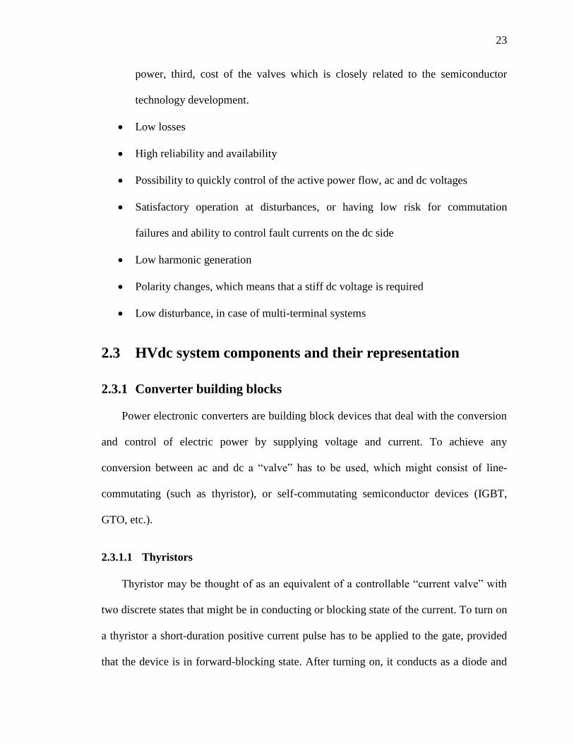
2.3.1.1 Thyristors
Thyristor may be thought of as an equivalent of a controllable “current valve” with
two discrete states that might be in conducting or blocking state of the current. To turn on
a thyristor a short-duration positive current pulse has to be applied to the gate, provided
that the device is in forward-blocking state. After turning on, it conducts as a diode and
24
gate signal may be removed. Thyristor cannot be made to turn off by pulse application.
To turn it off, the current passing through the device should have a “zero-crossing”.
Currently the most powerful thyristors can handle the voltages/currents at the level of 8-
10 kV/3-4 kA. They may be connected in series or parallel, to suit a specific voltage /
current / power application. At the highest level of power still there is no practical
substitute for this device. They have very low conduction, and switching losses. Thyristor
symbol and its I-V characteristics may be seen in Figure 2.1, [65].
VBRF1
+VA
+IA
VBRF2
IG1=0IG2>IG1
-VA
-IA
Figure 2.1 Thyristor symbol and its I-V characteristics
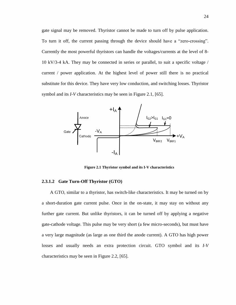
2.3.1.2 Gate Turn-Off Thyristor (GTO)
A GTO, similar to a thyristor, has switch-like characteristics. It may be turned on by
a short-duration gate current pulse. Once in the on-state, it may stay on without any
further gate current. But unlike thyristors, it can be turned off by applying a negative
gate-cathode voltage. This pulse may be very short (a few micro-seconds), but must have
a very large magnitude (as large as one third the anode current). A GTO has high power
losses and usually needs an extra protection circuit. GTO symbol and its I-V
characteristics may be seen in Figure 2.2, [65].
25
Figure 2.2 GTO symbol and its I-V characteristics
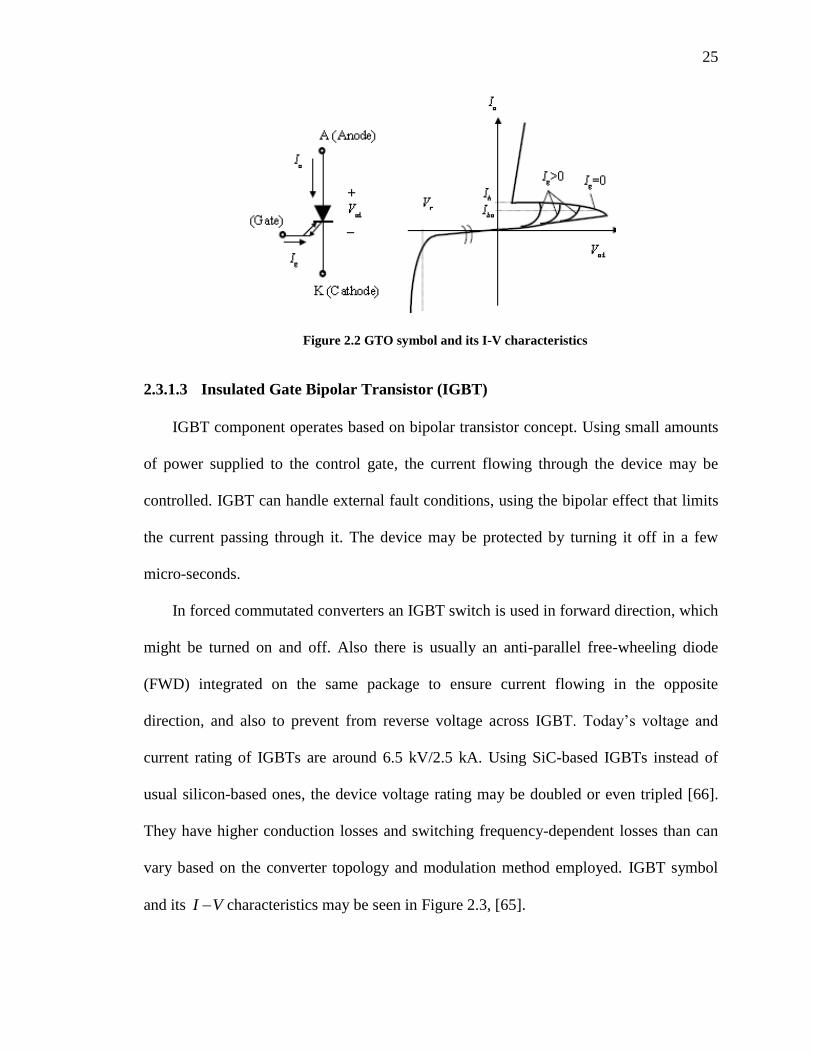
2.3.1.3 Insulated Gate Bipolar Transistor (IGBT)
IGBT component operates based on bipolar transistor concept. Using small amounts
of power supplied to the control gate, the current flowing through the device may be
controlled. IGBT can handle external fault conditions, using the bipolar effect that limits
the current passing through it. The device may be protected by turning it off in a few
micro-seconds.
In forced commutated converters an IGBT switch is used in forward direction, which
might be turned on and off. Also there is usually an anti-parallel free-wheeling diode
(FWD) integrated on the same package to ensure current flowing in the opposite
direction, and also to prevent from reverse voltage across IGBT. Today‟s voltage and
current rating of IGBTs are around 6.5 kV/2.5 kA. Using SiC-based IGBTs instead of
usual silicon-based ones, the device voltage rating may be doubled or even tripled [66].
They have higher conduction losses and switching frequency-dependent losses than can
vary based on the converter topology and modulation method employed. IGBT symbol
and its VI characteristics may be seen in Figure 2.3, [65].
26
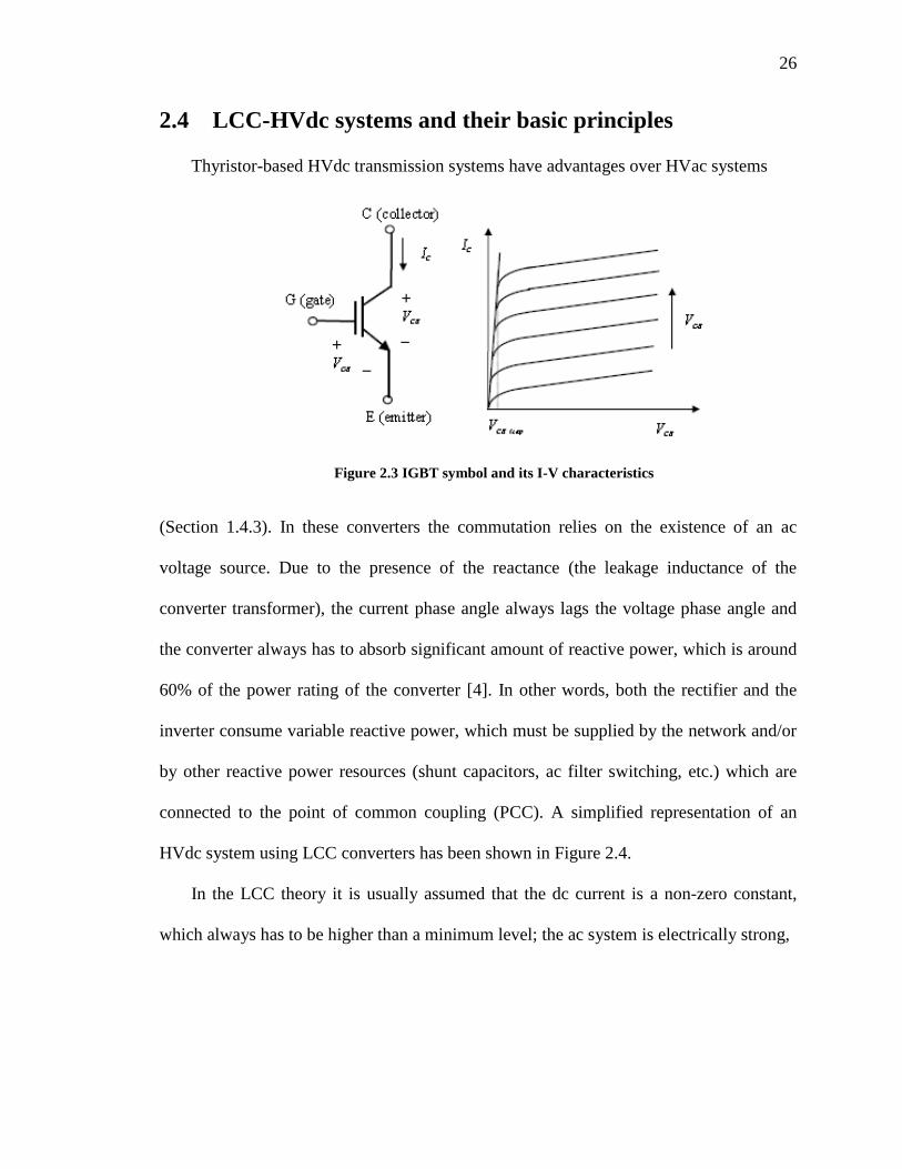
2.4 LCC-HVdc systems and their basic principles
Thyristor-based HVdc transmission systems have advantages over HVac systems
Figure 2.3 IGBT symbol and its I-V characteristics
(Section 1.4.3). In these converters the commutation relies on the existence of an ac
voltage source. Due to the presence of the reactance (the leakage inductance of the
converter transformer), the current phase angle always lags the voltage phase angle and
the converter always has to absorb significant amount of reactive power, which is around
60% of the power rating of the converter [4]. In other words, both the rectifier and the
inverter consume variable reactive power, which must be supplied by the network and/or
by other reactive power resources (shunt capacitors, ac filter switching, etc.) which are
connected to the point of common coupling (PCC). A simplified representation of an
HVdc system using LCC converters has been shown in Figure 2.4.
In the LCC theory it is usually assumed that the dc current is a non-zero constant,
which always has to be higher than a minimum level; the ac system is electrically strong,
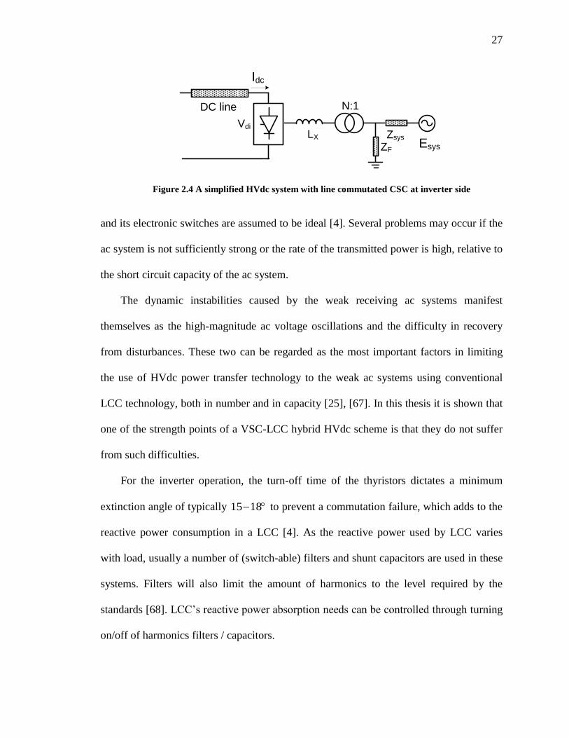
27
Idc
Vdi
LX
N:1
Zsys
ZF
DC line
Esys
Figure 2.4 A simplified HVdc system with line commutated CSC at inverter side
and its electronic switches are assumed to be ideal [4]. Several problems may occur if the
ac system is not sufficiently strong or the rate of the transmitted power is high, relative to
the short circuit capacity of the ac system.
The dynamic instabilities caused by the weak receiving ac systems manifest
themselves as the high-magnitude ac voltage oscillations and the difficulty in recovery
from disturbances. These two can be regarded as the most important factors in limiting
the use of HVdc power transfer technology to the weak ac systems using conventional
LCC technology, both in number and in capacity [25], [67]. In this thesis it is shown that
one of the strength points of a VSC-LCC hybrid HVdc scheme is that they do not suffer
from such difficulties.
For the inverter operation, the turn-off time of the thyristors dictates a minimum
extinction angle of typically 1815 to prevent a commutation failure, which adds to the
reactive power consumption in a LCC [4]. As the reactive power used by LCC varies
with load, usually a number of (switch-able) filters and shunt capacitors are used in these
systems. Filters will also limit the amount of harmonics to the level required by the
standards [68]. LCC‟s reactive power absorption needs can be controlled through turning
on/off of harmonics filters / capacitors.
28
In many HVdc systems with low SCR the ac voltage fluctuations, even without
actual instability, can be harmful for ac equipment, and so the quality of power supply
and the probability of commutation failure will increase on the dc side. Consequently the
link rating is determined on the basis of minimum safe SCR. Also an active power
change causes an equivalent reactive power change, resulting in an ac system voltage
fluctuation. The recommendation is that for successful conventional LCC operation, the
strength of connected ac systems should be greater than 2.0 [69]; part of this restriction is
because of the conventional operation modes of LCC converter controls.
The weaker the ac system (i.e. the lower the ratio of the short circuit capacity of the
ac system to the dc link power) is, the greater the undesirable effects and the ac/dc
interaction phenomena [5]. The problems associated with the interaction between HVdc
schemes and weak ac systems can be found in [8], [9], [10], [69], [70], [71]. The
difficulty of providing the voltage support to alleviate some of the difficulties related to
operation under weak ac systems using different types of compensators has been reported
in [9], where the studied system has the SCR = 1.5. Some of the problems associated with
weak ac systems are: high temporary over voltages, e.g. at load rejection [58], [71]; low
resonant frequency [58]; long clearing time after a fault [71]; voltage / power instability
[20]; core saturation instability[17], [20], [72]; harmonic generation/frequency instability
[71], [72], [73]. The frequency instability is a result of low inertia in the ac system.
Installation of large synchronous machines increases the inertia and stabilizes the
frequency. A combination of the second harmonic parallel resonance on the ac side and a
fundamental frequency resonance on the dc side can result in core saturation instability
[9], [10].
29
The maximum available power (MAP) from a dc link feeding power into an ac
system is affected by the SCR, the transformer reactance, minimum extinction angle ( ),
system damping, the shunt capacitors and the ac filters [74]. Increasing dcI beyond the
MAP point causes lower real power generation and demands more reactive power; it
finally causes ac voltage collapse. The weaker the ac system (the smaller the SCR), the
smaller the MAP peak and the faster the ac voltage will drop.
In conventional LCC converters, the dc line power flow can be controlled by
controlling the dc voltage at the receiving-end converter (inverter) at a constant value,
and by letting the sending-end converter (the rectifier) control the dc current. In these
systems it is not possible to change the direction of dc current. To change the power flow
direction, the dc voltage polarity of transmission line must change.
The highest rating for an LCC converter has 6400 MW, 800 kV dc voltage, which
is under construction [75].
2.5 VSC-HVdc systems and their basic principles
Forced commutated semiconductor devices such as GTO (Section 2.3.1.2) or IGBT
(Section 2.3.1.3) are used as the main switching device in a VSC converter. These
devices have the ability of tuning off the current by applying a negative signal to the
device‟s gate. Adding an anti-parallel diode to the device lets the current flow in both
directions, so the device must be designed to maintain only forward blocking voltage. For
square wave operation, each valve in a leg conducts current during only one-half cycle,
which means that each phase is connected to the positive pole during one half cycle and
is connected to the negative pole during the other half of the cycle. In order to have a
30
symmetric three-phase system it is required that components turn on at 120 intervals
from each other.
It is possible to refer all of the potentials to a virtual midpoint on the dc side.
Potentials at each leg of the converter can be written based on differences in line
voltages, this way the potential of the neutral point of the secondary of the transformer
would be a square wave. VSC generates its own voltage source with controlled amplitude
and phase angle. This is the most important difference between a LCC and a VSC in
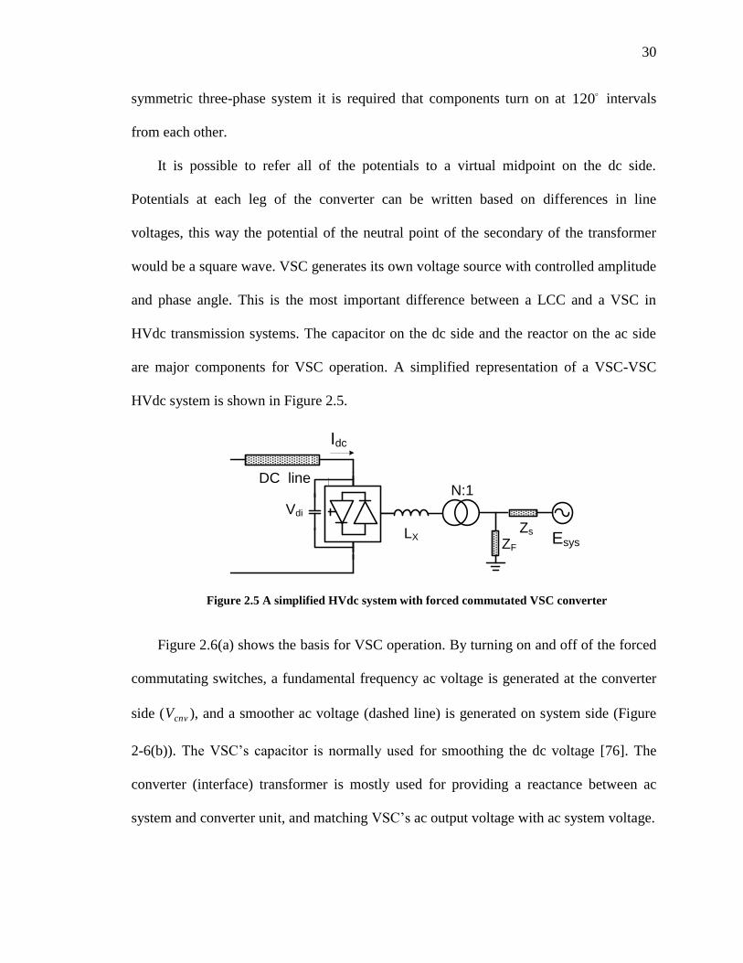
HVdc transmission systems. The capacitor on the dc side and the reactor on the ac side
are major components for VSC operation. A simplified representation of a VSC-VSC
HVdc system is shown in Figure 2.5.
Idc
N:1
Zs
ZF
DC line
LX Esys
Vdi
Figure 2.5 A simplified HVdc system with forced commutated VSC converter
Figure 2.6(a) shows the basis for VSC operation. By turning on and off of the forced
commutating switches, a fundamental frequency ac voltage is generated at the converter
side ( cnvV ), and a smoother ac voltage (dashed line) is generated on system side (Figure
2-6(b)). The VSC‟s capacitor is normally used for smoothing the dc voltage [76]. The
converter (interface) transformer is mostly used for providing a reactance between ac
system and converter unit, and matching VSC‟s ac output voltage with ac system voltage.
31
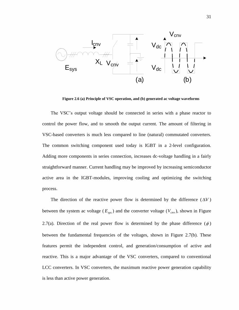
Figure 2.6 (a) Principle of VSC operation, and (b) generated ac voltage waveforms
The VSC‟s output voltage should be connected in series with a phase reactor to
control the power flow, and to smooth the output current. The amount of filtering in
VSC-based converters is much less compared to line (natural) commutated converters.
The common switching component used today is IGBT in a 2-level configuration.
Adding more components in series connection, increases dc-voltage handling in a fairly
straightforward manner. Current handling may be improved by increasing semiconductor
active area in the IGBT-modules, improving cooling and optimizing the switching
process.
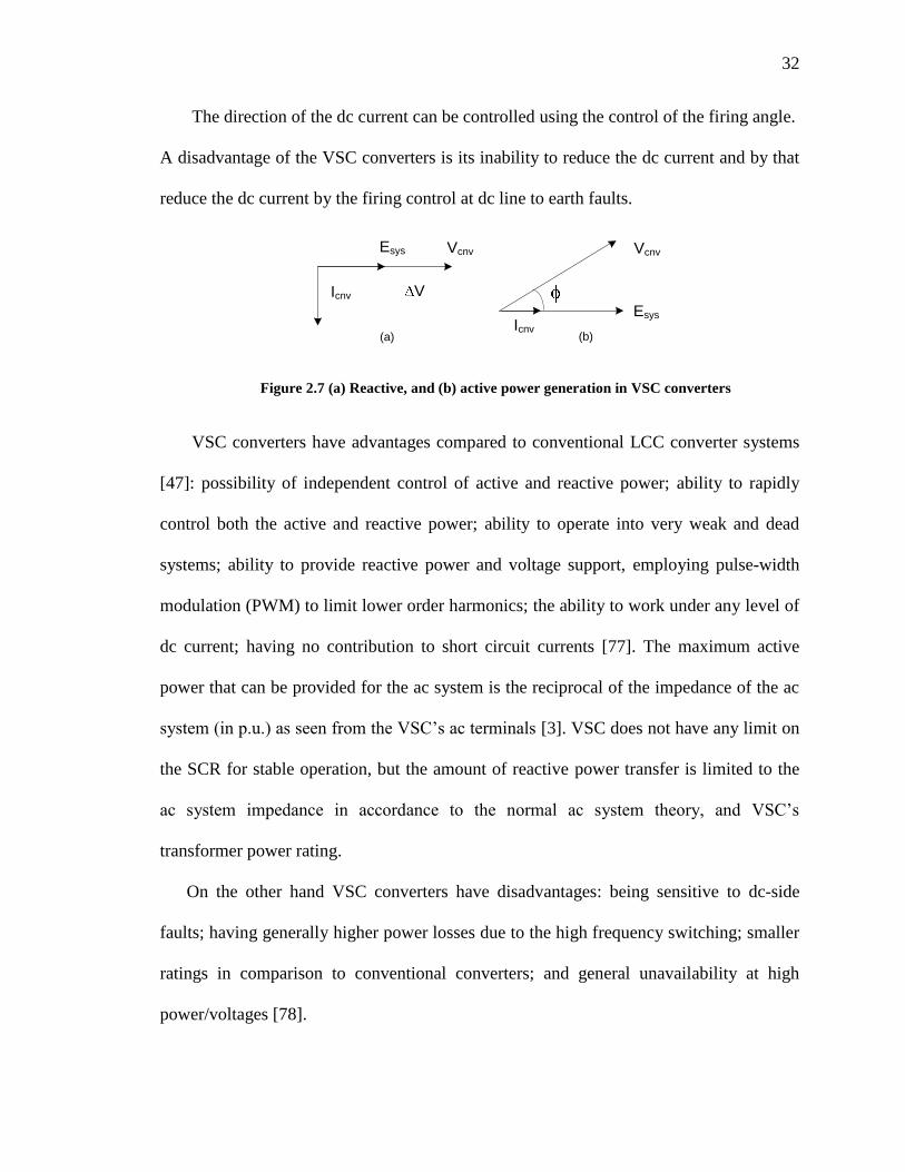
The direction of the reactive power flow is determined by the difference ( V )
between the system ac voltage ( sysE ) and the converter voltage ( cnvV ), shown in Figure
2.7(a). Direction of the real power flow is determined by the phase difference ( )
between the fundamental frequencies of the voltages, shown in Figure 2.7(b). These
features permit the independent control, and generation/consumption of active and
reactive. This is a major advantage of the VSC converters, compared to conventional
LCC converters. In VSC converters, the maximum reactive power generation capability
is less than active power generation.
V dc
V cnv
( a )
V cnv
( b )
E sys
X L
I cnv
V dc
32
The direction of the dc current can be controlled using the control of the firing angle.
A disadvantage of the VSC converters is its inability to reduce the dc current and by that
reduce the dc current by the firing control at dc line to earth faults.
VcnvEsys
Icnv V
Esys
Vcnv
Icnv
(a) (b)
Figure 2.7 (a) Reactive, and (b) active power generation in VSC converters
VSC converters have advantages compared to conventional LCC converter systems
[47]: possibility of independent control of active and reactive power; ability to rapidly
control both the active and reactive power; ability to operate into very weak and dead
systems; ability to provide reactive power and voltage support, employing pulse-width
modulation (PWM) to limit lower order harmonics; the ability to work under any level of
dc current; having no contribution to short circuit currents [77]. The maximum active
power that can be provided for the ac system is the reciprocal of the impedance of the ac
system (in p.u.) as seen from the VSC‟s ac terminals [3]. VSC does not have any limit on
the SCR for stable operation, but the amount of reactive power transfer is limited to the
ac system impedance in accordance to the normal ac system theory, and VSC‟s
transformer power rating.
On the other hand VSC converters have disadvantages: being sensitive to dc-side
faults; having generally higher power losses due to the high frequency switching; smaller
ratings in comparison to conventional converters; and general unavailability at high
power/voltages [78].
33
The largest VSC-HVdc converter valves (as of 2010) based on IGBTs has the power
rating of 400 MW, voltage rating of 200 kV and maximum dc current of 1050 A [79].
Increasing the valve switching voltage leads to higher influence of stray capacitances.
The challenge in increasing the dc voltage to levels as high as 300kV is to achieve
sufficient voltage sharing between the series-connected IGBT components in both
switching, and blocking conditions. Lowest valve cost per MW is achieved at maximum
ac-current. The main limiting factors here are maximum semiconductor temperature and
switching capability of the IGBT module. The temperature of the IGBT is largely
governed by the losses generated, which come from two main contributors of conduction
and switching. As semiconductor technology advances, conduction losses are being
lowered continuously. Switching losses generally depend more on the converter
topology. The switching frequency then determines the average switching losses. A low
switching frequency reduces the power dissipation but it also affects the controllability of
the converter so there is a trade-off between them. Increased current handling of IGBTs
may be reached by optimizing the switching pattern and improving the heat sink.
The quality of the output voltage can be improved using the Pulse Width Modulation
(PWM) method [65]. In the most straightforward implementation, generation of the
desired output voltage is achieved by comparing the desired reference waveform
(modulating signal) with a high-frequency triangular „carrier‟ wave (Figure 2.8).
In this method, when the modulating (reference) signal is larger (smaller) than the
carrier waveform, the output voltage is switched to its high (low) state. Using this
method, it is possible to vary the ratio between the fundamental value of actual
component of the converter output voltage and of the un-modulated output voltage of the
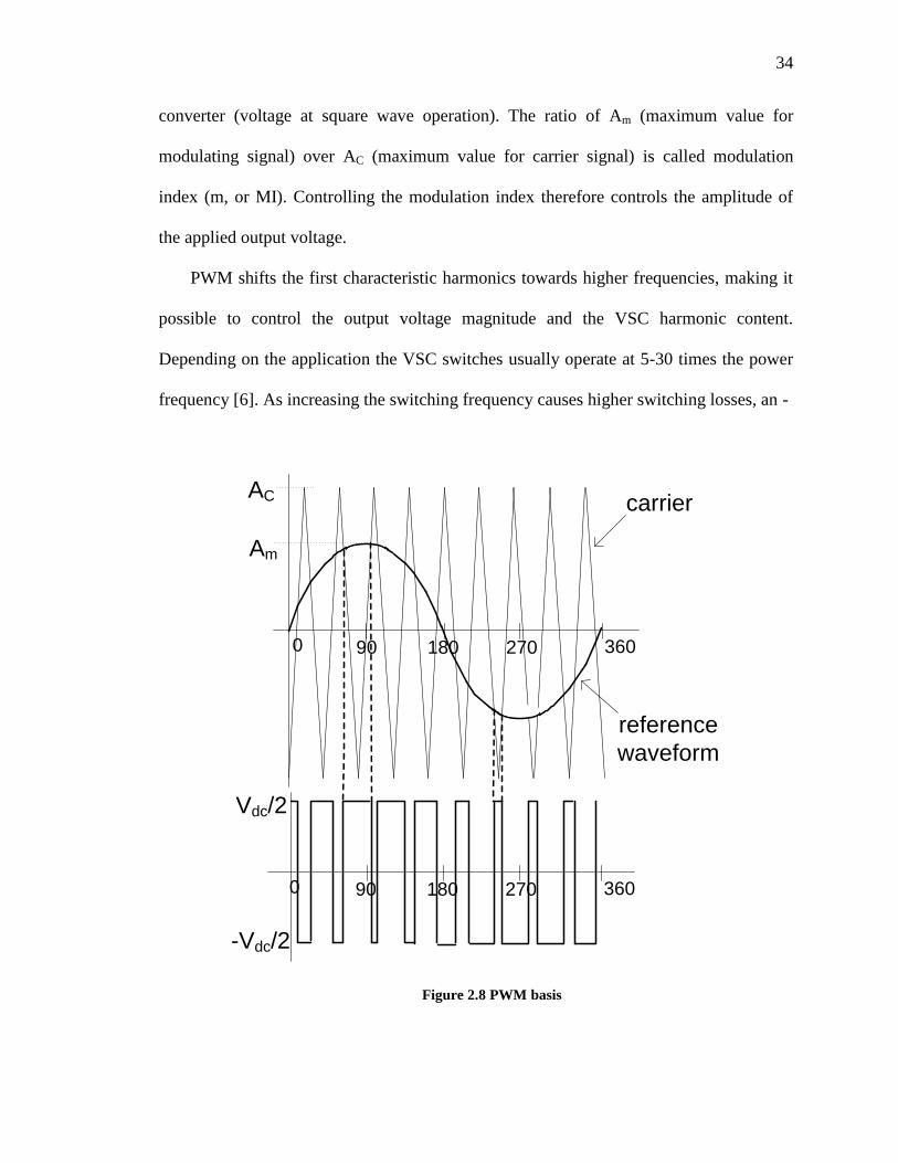
34
converter (voltage at square wave operation). The ratio of Am (maximum value for
modulating signal) over AC (maximum value for carrier signal) is called modulation
index (m, or MI). Controlling the modulation index therefore controls the amplitude of
the applied output voltage.
PWM shifts the first characteristic harmonics towards higher frequencies, making it
possible to control the output voltage magnitude and the VSC harmonic content.
Depending on the application the VSC switches usually operate at 5-30 times the power
frequency [6]. As increasing the switching frequency causes higher switching losses, an -
36018090 2700
AC
Am
carrier
reference
waveform
36018090 2700
Vdc/2
-Vdc/2
Figure 2.8 PWM basis
35
optimization algorithm/method can be used to balance the harmonic level on one hand,
and parameters such as power losses, on the other hand. In this research, the Sinusoidal
Pulse Width Modulation (SPWM) has been used [82].
2.6 Converter arrangements
2.6.1 Arrangements for LCC-HVdc schemes
The thyristors of LCC may be configured as series/parallel, and in 6/12-pulse
converter configurations. They might also come with multi-tap inter-phase reactors. The
HVdc link itself may be classified into mono-, bi-, or homo-polar link categories [80].
Standard LCC-HVdc systems may be put into service in different ways:
Back-to-Back scheme, with two ac systems physically located in the same place,
Point-to-Point scheme, to transfer electric power through dc transmission or
cables between two geographical locations,
Multi-Terminal scheme, in which three or more geographically separated HVdc
substations connected either in series or parallel configurations to each other,
Unit Connection scheme, in which a dc transmission is applied at the point of
generation to the converter transformer of rectifier.
With current technology of 800 kV dc transmission lines, series / parallel
connected 12-pulse groups can deliver electrical power of around 7200 MW [75].
2.6.2 Arrangements for VSC-HVdc schemes
The desired output waveform of a VSC is a good approximation of a sine-wave,
which may be constructed using different methods [14]. The converters can be arranged
in different topologies, with varying number of dc voltage levels, inputs/outputs and
36
different levels of complexity in their switching patterns [6]. By combining the 2-, 3- or
multi-level phase unit topologies for converters the 2-, 3-, or multi-level (6-, 12- or n-
pulse) converter systems are created accordingly [73]. Combining the output from several
phase units and/or repeatedly switching the valves will help in reducing the harmonics
[26]. If the number of pulses is higher, the converter will be bigger, more expensive and
must use more complicated control methods. Converters may be connected in series,
parallel, or both, at dc terminals; and series or parallel at ac terminals of the converter
units [6].
In a 2-level phase unit, PWM technique brings the possibility of direct control on the
fundamental magnitude of the output voltage amplitude [80]. The switching may also be
arranged to cancel out the characteristic harmonics using Selective Harmonic Elimination
Method (SHEM) [81].
2.7 HVdc controls
2.7.1 LCC controls
Earlier HVdc schemes used individual phase control systems, where the firing
instants were determined individually for each valve. Using equi-distant firing control the
time interval between valve firings would be equal, and matches an angle of
60 .Individual phase control method results in different time intervals between the
firings, and generates higher non-characteristic harmonic contents. In practice, control
blocks such as VDCOL (Voltage Dependent Current Order Limiter) are needed to reduce
the current order at large reductions of the dc voltage.
The control system in an LCC-HVdc system attempts to maintain constant dc current
and voltage in the dc line. In practice, the rectifier usually sets the dc current and the
37
inverter sets the dc voltage. Then the current error is measured, amplified and filtered.
Based on the output signal, pulses will be generated at certain times for equi-distant
firing. These pulses must be converted to valve firing pulses. Current-control is generally
required to have a quick response, while voltage-control has a comparably slower
response to avoid unstable control interaction [4].
The LCC has different control modes. The preferred modes of control are:
The inverter controls the dc voltage, under steady state conditions, by maintaining
a constant extinction angle which causes the dc voltage to drop with increasing dc
current. As the ac system gets weaker, the droop will be steeper.
The inverter can operate in a dc-voltage controlling mode, which demands the
extinction angle (to increase beyond its minimum setting. As long as the delay
angle (is not at its minimum limit (usually 5 ), the rectifier must control the dc
current if the inverter is operating in a minimum constant-or constant-voltage
characteristic. If the system controls do not have a constant dc voltage-control, the
control and the tap changer will provide the dc voltage control.
By selecting the minimum value among the outputs of constant-current, voltage, and
extinction angle controls, a control characteristic is achieved. In order to have a stable dc
current-control the dc current order of the inverter has to be smaller than that of the
rectifier by the current margin, the intersection of them indicates the steady-state
(operating point) of the LCC. Different features of classical modified LCC control are
drawn in Figure 2.9 [5].
2.7.2 VSC controls
The VSC has the following main control levels [6]:
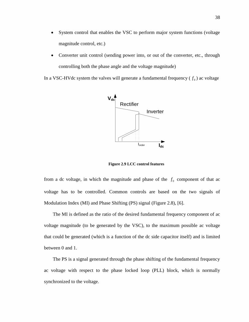
38
System control that enables the VSC to perform major system functions (voltage
magnitude control, etc.)
Converter unit control (sending power into, or out of the converter, etc., through
controlling both the phase angle and the voltage magnitude)
In a VSC-HVdc system the valves will generate a fundamental frequency ( 0f ) ac voltage
Idc
Vdc
Rectifier
Inverter
Iorder
Figure 2.9 LCC control features
from a dc voltage, in which the magnitude and phase of the 0f component of that ac
voltage has to be controlled. Common controls are based on the two signals of
Modulation Index (MI) and Phase Shifting (PS) signal (Figure 2.8), [6].
The MI is defined as the ratio of the desired fundamental frequency component of ac
voltage magnitude (to be generated by the VSC), to the maximum possible ac voltage
that could be generated (which is a function of the dc side capacitor itself) and is limited
between 0 and 1.
The PS is a signal generated through the phase shifting of the fundamental frequency
ac voltage with respect to the phase locked loop (PLL) block, which is normally
synchronized to the voltage.
39
Controlling the MI and PS for VSC-HVdc transmission applications is usually
achieved by either:
Direct control, in which the MI or PA will be directly adjusted by the parameters
being controlled, using the error signals as inputs to controllers,
Vector control (also known as decoupled control), which is a current control
strategy that decouples the adjusting action of the MI from the PS, [84].
The decoupled control is the conventional mode for VSC-HVdc converters and is
discussed later (Section 3.12.1).
In the direct control method the voltage magnitude may be controlled using MI.
When the voltage magnitude is greater than the voltage the reactive power will be
transferred into the ac side, which is similar to an over-excited synchronous generator,
and vice-versa.
In VSC-HVdc schemes, different control methods/modes can be used:
Ac voltage-control method, where the magnitude of the fundamental frequency
component of the ac voltage error, generates the phase-angle ( ) control signal
Power-control method, where the phase-angle error between fundamental
frequency component of ac voltage at the converter side, generates the signal for
phase-angle ( ) control
Reactive power-control mode, where other controllers act to maintain ac voltage
Dc voltage-control mode, where active power can be regulated through
controlling the capacitor voltage
40
Current-control method, which is part of the vector control itself; it lets current to
be controlled directly, or allows other parameters such as power, reactive power,
dc or ac voltage to be controlled,
Frequency-control mode, which controls the frequency of the oscillator.
In VSC-HVdc scheme the dc bus voltage must be controlled to force the desired real
power to flow in transmission line. Also the real and reactive power may be controlled
simultaneously, and independently of each other. Here, an ac system fault that depresses
ac voltage on phase(s) may lead to dc over voltage and over current. So every protection
action must be resolved quickly (within 10-20 milliseconds). When the system is
recovering from a disturbance, the controls must be fully functional, running free of
limits and not suffering from extended blocking of firing pulses.
2.8 Basic protection requirements
The protection is aimed at protecting the converter substation from damages caused
by external faults, or limiting the damage in case of an internal fault within the substation
itself.
2.8.1 LCC-based systems
A LCC-HVdc system needs substantial filters and shunt capacitor banks. If an LCC
is stopped from working (e.g. due to a short circuit), its reactive power needs would
become zero, which will lead to an overvoltage at terminal bus. Also, if the system‟s
impedance is high (low SCR), overvoltage at non-fundamental frequencies may also
appear. By fast controlling of reactive power in HVdc systems, it is possible to lower the
over voltages.
41
For an ac fault at the inverter side, usually commutation failure in converter valves is
expected, which in turn may lead to temporary interruption of power transmission. For
faults that occur on the dc side of the transmission system, the LCC automatically
reduces the current to a small value due to VDCOL operation. However this current
cannot be cleared by breaker opening, so the dc system can never be restarted without
operating both of the converters in inverter mode. For recovery from dc faults rectifier is
required to temporarily go into inverter mode and thus de-energize the line, referred to as
„forced retard‟ [5].
2.8.2 VSC-based systems
VSC-HVdc protection is very similar to LCC-HVdc protection. In external
temporary faults such as voltage dips, different ac temporary over voltages, ac voltage
phase shifting and ac voltage unbalances the VSC may have to stop power transmission
until complete clearing of the fault. If the fault happens in the dc overhead transmission
line in majority of the cases it would be a temporary one, but for the first time in a recent
project to be commissioned soon in Caprivi project [96], some solution for overhead
transmission line against dc fault and lightning has been proposed. In the cable
transmission systems, however, it is likely that dc fault to be permanent and the converter
should be shut down. In such cases as direct current will keep feeding the fault by the
reverse diodes in the connected terminals, and in order to clear the fault, the ac circuit
breakers at all terminals have to trip.
In case of internal faults, such as internal ac bus fault, dc bus fault or component
failure, the protection equipment in VSC substation will isolate the faulty element and
shuts down the transmission system.
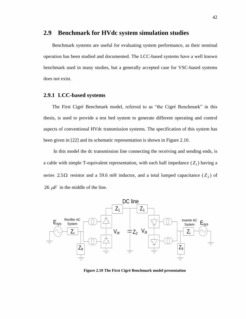
42
2.9 Benchmark for HVdc system simulation studies
Benchmark systems are useful for evaluating system performance, as their nominal
operation has been studied and documented. The LCC-based systems have a well known
benchmark used in many studies, but a generally accepted case for VSC-based systems
does not exist.
2.9.1 LCC-based systems
The First Cigré Benchmark model, referred to as “the Cigré Benchmark” in this
thesis, is used to provide a test bed system to generate different operating and control
aspects of conventional HVdc transmission systems. The specification of this system has
been given in [22] and its schematic representation is shown in Figure 2.10.
In this model the dc transmission line connecting the receiving and sending ends, is
a cable with simple T-equivalent representation, with each half impedance ( 1Z ) having a
series 5.2 resistor and a 59.6 mH inductor, and a total lumped capacitance ( 2Z ) of
F 26 in the middle of the line.
Vdr Vdi
Zfr
Zr
EsysRectifier AC
System
Z1 Z1
Zfi
Zi
Inverter AC
System
DC line
Z2
Esys
Figure 2.10 The First Cigré Benchmark model presentation
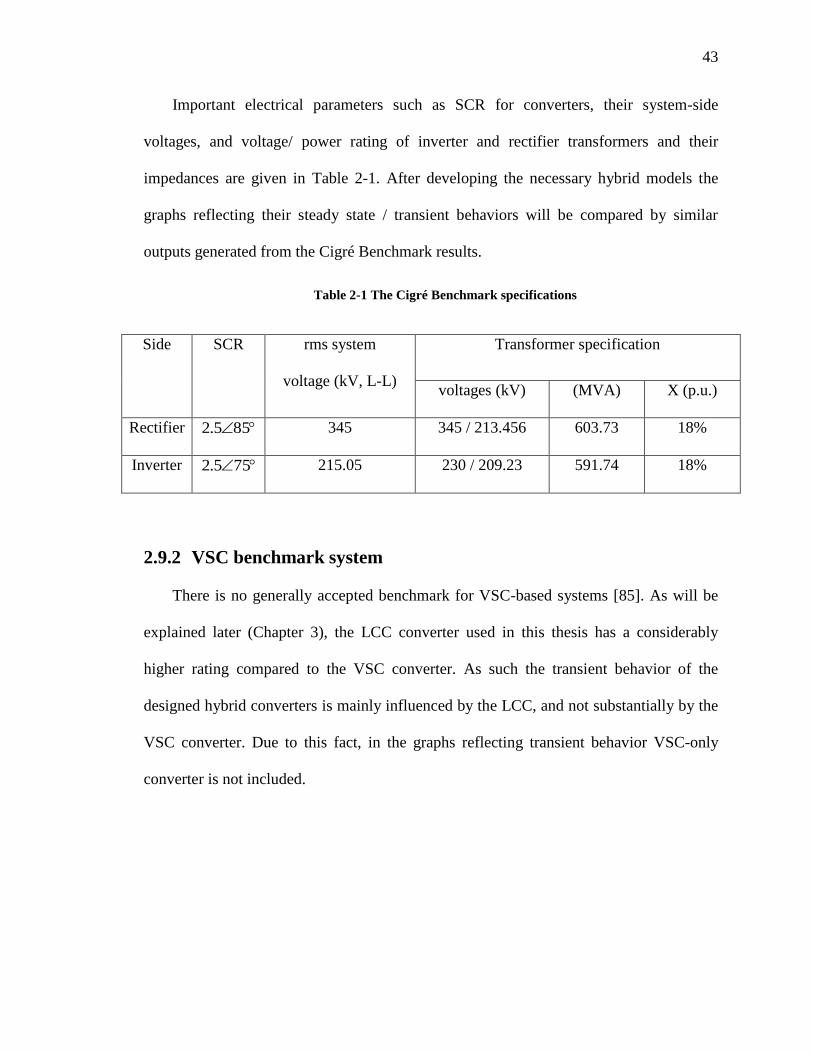
43
Important electrical parameters such as SCR for converters, their system-side
voltages, and voltage/ power rating of inverter and rectifier transformers and their
impedances are given in Table 2-1. After developing the necessary hybrid models the
graphs reflecting their steady state / transient behaviors will be compared by similar
outputs generated from the Cigré Benchmark results.
Table 2-1 The Cigré Benchmark specifications
Side SCR rms system
voltage (kV, L-L)
Transformer specification
voltages (kV) (MVA) X (p.u.)
Rectifier 855.2 345 345 / 213.456 603.73 18%
Inverter 755.2 215.05 230 / 209.23 591.74 18%
2.9.2 VSC benchmark system
There is no generally accepted benchmark for VSC-based systems [85]. As will be
explained later (Chapter 3), the LCC converter used in this thesis has a considerably
higher rating compared to the VSC converter. As such the transient behavior of the
designed hybrid converters is mainly influenced by the LCC, and not substantially by the
VSC converter. Due to this fact, in the graphs reflecting transient behavior VSC-only
converter is not included.
Chapter 3: Hybrid HVdc Configurations
3.1 Introduction
Converters used in HVdc transmission systems have traditionally been built based on
conventional converters (LCC), and recently sometimes as Voltage-Sourced Converters
(VSC). The points of strength and weakness of LCC-based and VSC-based HVdc
converters were mentioned (see Chapter 2). It is highly desirable to have an HVdc system
which preserves the combined advantages of an LCC and a VSC converter in one unit,
without suffering from their disadvantages. These properties may be addressed in a
hybrid converter structure discussed in this chapter.
The objective of this chapter is to explain the concept, design and control
philosophy, along with electrical properties of the two proposed series and parallel
converters, terminating into a very weak ac network. As is pointed out later in this
chapter, in order to build a hybrid converter using LCC and VSC converters, an LCC-
only converter (the First Cigré Benchmark) was selected as the design base. Then parts of
the electrical parameters were re-designed and a combined version of LCC-VSC HVdc
system controls was introduced and implemented. Finally the two controllers of the
hybrid inverter and LCC-only converter on the rectifier side were coordinated and
adjusted. These steps will be discussed in detail in this chapter.
3.2 Hybrid converter HVdc transmission systems
Out of different possible configurations for a hybrid converter HVdc transmission
system, the series and parallel ones were selected for analysis. More complicated
configurations are also possible, but it requires more complicated control methods and
45
coordination, more semiconductor components, higher costs and more space. A hybrid
converter HVdc transmission system would affect power system dynamic performance
[86], [87] and can offer the following benefits:
Generating the needed LCC reactive power by VSC converter,
Independent controlling of the active power from its reactive power,
Supplying a very weak ac system,
Reducing the risk of commutation failure using fast ac voltage control,
Reducing dramatically the size of the ac filters, if the VSC at the same time can
be used as an active filter
Possibility of using the hybrid converters in multi-terminal systems based on fast
dc voltage control.
3.3 Hybrid converter arrangements
In this section the general electrical description of both SHC and PHC, along with
their system requirements will be discussed.
3.3.1 Series Hybrid Converter (SHC)
A series hybrid converter consists of a series connection of one line-commutated
(current-sourced) converter and one forced-commutated (voltage-sourced) converter, as
shown in Figure 3.1. In this configuration the VSC converter generates the reactive
power demand of the LCC converter and also supports the ac terminal voltage, while
participating in active power transfer. This configuration may be considered for the
following situations:
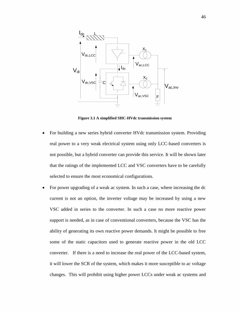
46
Vac,Inv
X1
X2
Vac,LCC
Vac,VSC
Vdc,LCC
Vdc,VSC
Vdi
C
Idc
Idc L
F
Figure 3.1 A simplified SHC-HVdc transmission system
For building a new series hybrid converter HVdc transmission system. Providing
real power to a very weak electrical system using only LCC-based converters is
not possible, but a hybrid converter can provide this service. It will be shown later
that the ratings of the implemented LCC and VSC converters have to be carefully
selected to ensure the most economical configurations.
For power upgrading of a weak ac system. In such a case, where increasing the dc
current is not an option, the inverter voltage may be increased by using a new
VSC added in series to the converter. In such a case no more reactive power
support is needed, as in case of conventional converters, because the VSC has the
ability of generating its own reactive power demands. It might be possible to free
some of the static capacitors used to generate reactive power in the old LCC
converter. If there is a need to increase the real power of the LCC-based system,
it will lower the SCR of the system, which makes it more susceptible to ac voltage
changes. This will prohibit using higher power LCCs under weak ac systems and
47
can be achieved by using a series VSC converter, which will create a SHC
converter.
Another advantage of the SHC converter is that during a solid ac side fault, no real
power is delivered. As a result zero power will be absorbed or delivered by the VSC
terminal. On the other hand the previous dc current setting is still valid and the dc current
will be flowing into series inverter circuit as before. This current will cause over-charging
of VSC‟s capacitor before any controller takes an action. The amount of over-charging
depends on the fault impedance and speed of dc current controller response. The low
power demand would continue as long as the fault exists, or before any appropriate
counter-action is taken. This will demand extra over-voltage protection for the capacitor.
One of the drawbacks of the SHC configuration is the complexity of “dynamic”
power reversal, which needs two sets of operations. One is changing the voltage polarity
across LCC rectifier and LCC inverter, without changing the current direction; here, the
firing angle of these thyristors must be interchanged; secondly using mechanical switches
to interchange the input-output connections for reversing the voltage polarity across the
VSC. To do so, the converters need a complete shutdown. This mechanical switch will
add considerably to system cost.
3.3.2 Parallel Hybrid Converter (PHC)
A parallel hybrid converter consists of a parallel connection of one line-commutated
(current-sourced) converter and one forced-commutated (voltage-sourced) converter. A
simplified representation for a parallel hybrid converter system (abbreviated as PHC in
this research) is shown in Figure 3.2.
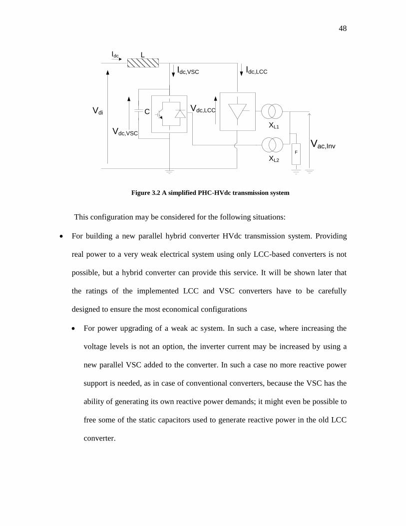
48
Vac,Inv
XL1
XL2
Vdc,VSC
Vdc,LCCVdi C
Idc L
Idc,LCCIdc,VSC
F
Figure 3.2 A simplified PHC-HVdc transmission system
This configuration may be considered for the following situations:
For building a new parallel hybrid converter HVdc transmission system. Providing
real power to a very weak electrical system using only LCC-based converters is not
possible, but a hybrid converter can provide this service. It will be shown later that
the ratings of the implemented LCC and VSC converters have to be carefully
designed to ensure the most economical configurations
For power upgrading of a weak ac system. In such a case, where increasing the
voltage levels is not an option, the inverter current may be increased by using a
new parallel VSC added to the converter. In such a case no more reactive power
support is needed, as in case of conventional converters, because the VSC has the
ability of generating its own reactive power demands; it might even be possible to
free some of the static capacitors used to generate reactive power in the old LCC
converter.
49
At present, VSC ratings are limited to a smaller value than for LCC; because of the
difficulty in series connecting forced devices such as IGBT to make a high voltage valve.
In either case the voltage rating will be limited to the highest level possible that the
semi-conductor technology (IGBT or GTO) supports, which today is much less than the
voltage rating of thyristors. Due to the practical voltage limitation mentioned, it would be
difficult to use this topology for very high-voltage applications. In a fresh design, more
options are available for selecting the appropriate voltage/current levels in the hybrid
inverter but compared to SHC option, the VSC‟s power share in transmitting high power
to weak ac systems is expected to be limited.
One of the drawbacks of the PHC converter is the complexity of “dynamic” power
reversal, which needs the voltage polarity of the circuit to be reversed. To do this, the
thyristor connections must remain unchanged in both the LCC rectifier and LCC inverter.
The firing angle range must be suitably modified to the appropriate operating
requirements, i.e. rectifier (with alpha angle less than 90°), or inverter (with alpha angle
bigger that 90°). Here, similar to SHC case, the mechanical switches will reverse the
VSC inverter input-output connections. This will add considerably to system cost. Again,
power reversal demands complete converter shutdown.
3.4 Main components of HVdc electrical system
One of the advantages of the hybrid converters is that they can operate into very
weak systems. The following section discusses the design requirements of hybrid
converters. For purpose of discussion a specific candidate system is envisaged, which is
discussed below.
50
3.4.1 The inverter ac network equivalent
The ac network on the inverter side is represented by a RL-type equivalent circuit
(Figure 3.3), connected to an ac terminal with 230 kV voltage, to deliver the rated
electrical power of 1000 MW (1 p.u.), with a short-circuit ratio (SCR) equal to 1.0, which
represents a very weak electrical network [4]. Such a low SCR is out of the range of any
LCC-only based converter. Such a very low SCR is used to investigate the ability of
hybrid converter to operate in very weak ac systems. VSC has the ability to work with
very low SCR systems, but as this is a hybrid converter, the overall system performance
is not dictated by just one of the converters.
The SCR is a measure of the ac network strength at fundamental frequency with
respect to its transmitted dc power, defined as short circuit MVA rating, divided by
system dc power:
dcP
SCMVASCR (3-1)
The effective-short-circuit-ratio (ESCR) is a measure of system strength when the effect
of passive shunt compensating devices (i.e. filters, capacitors) is included:
dc
C
P
QSCRESCR (3-2)
In (3-2) CQ is the reactive power generation (in Mvar) and dcP is dc power rating of the
HVdc system.
The system impedances are predominantly inductive. Here a system damping angle
of 75° is assumed for the impedance as this is typical. The system ac network equivalent
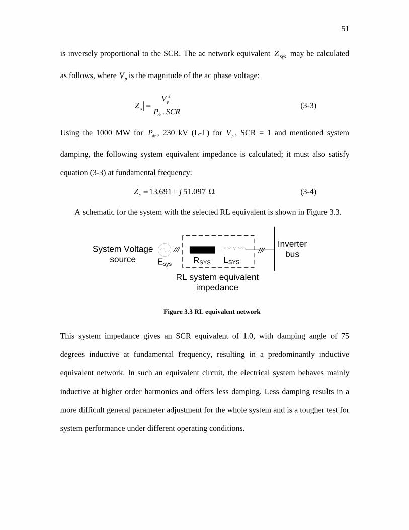
51
is inversely proportional to the SCR. The ac network equivalent sysZ may be calculated
as follows, where pV is the magnitude of the ac phase voltage:
SCRP
VZ
dc
p
s .
2
(3-3)
Using the 1000 MW for dc
P , 230 kV (L-L) for p
V , SCR = 1 and mentioned system
damping, the following system equivalent impedance is calculated; it must also satisfy
equation (3-3) at fundamental frequency:
097.51 691.13 jZs
(3-4)
A schematic for the system with the selected RL equivalent is shown in Figure 3.3.
LSYS
System Voltage
source
Inverter
bus
RL system equivalent
impedance
Esys RSYS
Figure 3.3 RL equivalent network
This system impedance gives an SCR equivalent of 1.0, with damping angle of 75
degrees inductive at fundamental frequency, resulting in a predominantly inductive
equivalent network. In such an equivalent circuit, the electrical system behaves mainly
inductive at higher order harmonics and offers less damping. Less damping results in a
more difficult general parameter adjustment for the whole system and is a tougher test for
system performance under different operating conditions.
52
3.4.2 The dc smoothing reactor
In conventional converters the smoothing inductors (reactors) are located at both
ends of the dc connection, between the dc filter and bypass breakers. In the back-to-back
schemes, the smoothing reactor can also be connected to the low-voltage side of dc loop
[98]. The reactor must [4]:
Limit the rate of rise of dc fault current to prevent commutation failures
Prevent the resonances in dc circuit at low order harmonic frequencies such as
multiples of 2 or 3 of the fundamental frequency (harmonics that originally start
from the ac system, like negative sequence and transformer saturation)
Reduce harmonic currents including limiting the telephone interference.
It is a complex matter to choose a feasible size for this reactor. This size is often selected
in the range of 100 to 300 mH for long-distance dc links and 30 to 80 mH for back-to-
back stations. Here a value of 200 mH is chosen for the smoothing reactor in both of the
hybrid HVdc alternatives, which meets the above mentioned objectives.
These reactors are of two basic design types: dry-type and oil-insulated reactors in
tank. The latter is an economical option for very high power levels. The reactor type
should be selected based on inductance, costs, maintenance and location of spare units,
and seismic requirements. Transiently, it must tolerate maximum dc voltage and short
circuit current. In steady state, tolerate sum of harmonic voltages.
3.4.3 Dc harmonics and dc filter circuits
The characteristic harmonic voltages on the dc side are of frequencies ,.12 k where
nk ,...2,1 , is the multiplier of the system fundamental frequency is ( 0f ). Despite the
smoothing reactors in the dc lines, the harmonic currents caused by these harmonics
53
voltages can exceed the allowed harmonic distortion level for communication
interference set by standards and need to be suppressed using dc filter circuits. Based on
the difference between these harmonics (for example the 12th
harmonics on the two sides)
the current harmonic of the order 12 may flow in the dc line. The configuration of the dc
filters is very similar to the filters normally used on the ac side of the HVdc station. In
cable transmission line, interference with communication circuits is minimal, so filters
can be avoided.
In the benchmark system used in this thesis to demonstrate the hybrid converters, dc
filters are not used because as the benchmark is developed for a cables system [68].
3.5 Hybrid system general description
The benefits offered by the hybrid topology are more applicable on the inverter side,
because an LCC-only type inverter is more likely to have commutation failure and other
voltage related problems when connected into a weak ac system. Hence in order to keep
the simulation simple, only the inverter of the Cigré Benchmark system was replaced
with the hybrid options. The original LCC of the benchmark was retained on the rectifier
side. As a result, both of the series and parallel hybrid converter options consist of two
six-pulse conventional LCC converters at the rectifier side. The inverter consists of series
and parallel connection of 2 six-pulse LCC-only converters to make a 12-pulse
configuration, and one VSC converter, to form the SHC and PHC hybrid converters,
respectively Connecting points B-C forms the series hybrid inverter, while connecting
points A-C and B-D forms the parallel hybrid inverter (Figure 3.4). In the SHC option,
the VSC is located between the LCC and ground to reduce the voltage insulation levels
(i.e., bushing insulation, etc.) of the VSC. This does increase the insulation levels
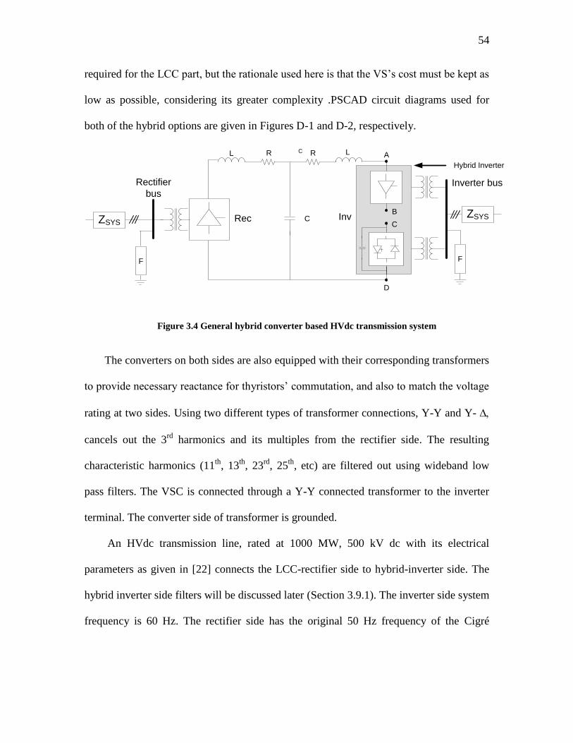
54
required for the LCC part, but the rationale used here is that the VS‟s cost must be kept as
low as possible, considering its greater complexity .PSCAD circuit diagrams used for
both of the hybrid options are given in Figures D-1 and D-2, respectively.
Rec Inv
L R R L
C
F
A
B
C
D
F
Hybrid Inverter
Inverter busRectifier
bus
ZSYSZSYS
C
Figure 3.4 General hybrid converter based HVdc transmission system
The converters on both sides are also equipped with their corresponding transformers
to provide necessary reactance for thyristors‟ commutation, and also to match the voltage
rating at two sides. Using two different types of transformer connections, Y-Y and Y-
cancels out the 3rd
harmonics and its multiples from the rectifier side. The resulting
characteristic harmonics (11th
, 13th
, 23rd
, 25th
, etc) are filtered out using wideband low
pass filters. The VSC is connected through a Y-Y connected transformer to the inverter
terminal. The converter side of transformer is grounded.
An HVdc transmission line, rated at 1000 MW, 500 kV dc with its electrical
parameters as given in [22] connects the LCC-rectifier side to hybrid-inverter side. The
hybrid inverter side filters will be discussed later (Section 3.9.1). The inverter side system
frequency is 60 Hz. The rectifier side has the original 50 Hz frequency of the Cigré
55
Benchmark model. The IGBT valves of the VSC are assumed to switch at 1620 Hz (27th
harmonic of 60 Hz) and thus will only contribute switching frequency harmonics.
The selection of power and voltage ratings is based on an optimization concept,
discussed below.
3.6 Hybrid design philosophy
The design of the hybrid system is described in the context of the 1000 MW, 500 kV
Cigré Benchmark model [22], which is to be the host system for the hybrid options. The
power and voltage rating for hybrid options are thus as for the Cigré Benchmark model.
The inverter side of the Cigré Benchmark model has been completely re-designed to
retrofit the VCS converter. This converter would appear in electrically series or parallel
connection to the LCC converter. The rectifier converter is left unchanged. From the
above discussion the total power for both of the simulated hybrid converters is 1000 MW,
under 500 kV dc transmission voltage level. The question is now how allocate the
proportion of this power to the LCC and VSC components.
3.6.1 Hybrid power and voltage/current allocation
The proposed method to find the suitable proportion of voltage for the SHC (and
current for the PHC) option between the LCC and VSC converters at the inverter side is
as follows. The key critical element chosen is optimizing (minimizing) the total system
expenses. The costs involved in construction of converters for HVdc transmission has
many components. It depends on price for the semiconductors used (thyristors for the
LCC converter and IGBT for VSC converters), number and size of filters, land, and a
number of issues specific to each project. The loss can also be included in cost analysis.
56
In this thesis, a detailed cost comparison was considered to be beyond the scope of the
work and hence it was not conducted. The ddifficulties in conducting a cost analysis
include the following:
The price for semiconductors used for making the valves is rapidly changing
overtime.
A sufficiently large number of VSC projects simply does not exist, to suggest an
established market price.
The cost information is not available in public domain for most awarded projects.
The method employed here optimizes a suitable cost function that establishes a
connection between converter voltage rating, and major system components‟ price. The
VSC is the most expensive component, hence to achieve the desired performance with
the least expense, i.e. least MVA, VSC is the actual objective used in the design. Based
on the nominal power ( nomP ) of the HVdc transmission system and the total dc voltage
rating the voltage and power rating for the converters at the hybrid-side may be
calculated. This very idea will be applied to both the series and parallel options here.
If nomP is the total power from the hybrid converter, and LCCP is the power rating of
the LCC converter, then the VSC converter‟s power rating is given by:
LCCnomVSC PPP (3-5)
Also the reactive power generated by the VSC must satisfy reactive power requirement of
the ac filters and the reactive power demand of the LCC converter at rated power.
Assuming the reactive power demand of the LCC converter to be approximately 60% of
the real power [4] and that part of this ( fQ ) is satisfied by the ac filters; the required
reactive power from the VSC converter becomes:
57
fLCCVSC QPQ * 6.0 (3-6)
Based on the above observations, the hybrid converter‟s total complex power MVA
rating becomes:
22 VSCVSCVSC QPS (3-7)
or
22 )*6.0()( fLCCLCCnomVSC QPPPS (3-8)
To select the relative ratings of the converters, it was decided to minimize VSCS ,
because the VSC is the most expensive element in the hybrid. If accurate relative costs,
including other cost elements like cost of land are known, a more precise rating estimate
would be possible. Considering the above, the optimum size of the VSC can be calculated
by taking the derivative of VSC‟s complex power with respect to LCCP and setting the
result equal to zero:
72.2
2.120 )(
fnom
optLCC
LCC
VSCQP
PP
S
(3-9)
Hence
)()( optLCCnomoptVSC PPP (3-10)
Based on this result the appropriate LCC and VSC transformer ratings can be determined.
Note that in this arrangement, all the reactive power of the LCC could have been
provided by the VSC converter. However, for absorbing the LCC-generated harmonics,
some filtering ( 0fQ ) is still required. The selection of fQ value is discussed later
(Section 3.9.1). Once LCCP is determined as (3-8), the voltage ratios for the VSC and
58
LCC for the series hybrid option are calculated (Appendix A.2). For the SHC option, the
voltage ratios are:
rateddc
LCCLCCdc
I
PV
,
, and LCCdcVSCdc VV ,, 500 (3-11)
For the PHC option, knowing that LCCdcV , equals VSCdcV , (500 kV), similar relations for
LCCdcI , and VSCdcI , can be written. Now similar calculations would result in the current
ratios for the parallel hybrid option (Appendix A.3).
Note that for the design in (3-8), the filter rating fQ must be first decided. The filter
reactive power generation of around 75 Mvar was enough for steady-state system
operation but it could not meet the THD (total harmonic distortion) and the individual
harmonic distortion levels, as specified by the standards [68]. fQ was selected to meet a
standard THD level of 2% and individual harmonic distortions of 1%, assuming 2%
tolerance in component magnitudes [88]. The filter ratings are specified in section 3.9.1.
At the same time it was of more interest to keep the reactive power generation to
lowest possible level so that load rejection overvoltage at inverter terminal is easier to
handle. Using an iterative method the final simulation-based optimized values of 103
Mvar for the SHC, and 110 Mvar for the PHC options were recognized suitable for fQ .
These values are much smaller than that of a conventional LCC configuration.
Based on these optimized magnitudes the apparent power rating for converter
transformers were calculated (Table 3-1). In this table VSC and LCC refer to voltage-
sourced converter and conventional converter, respectively.
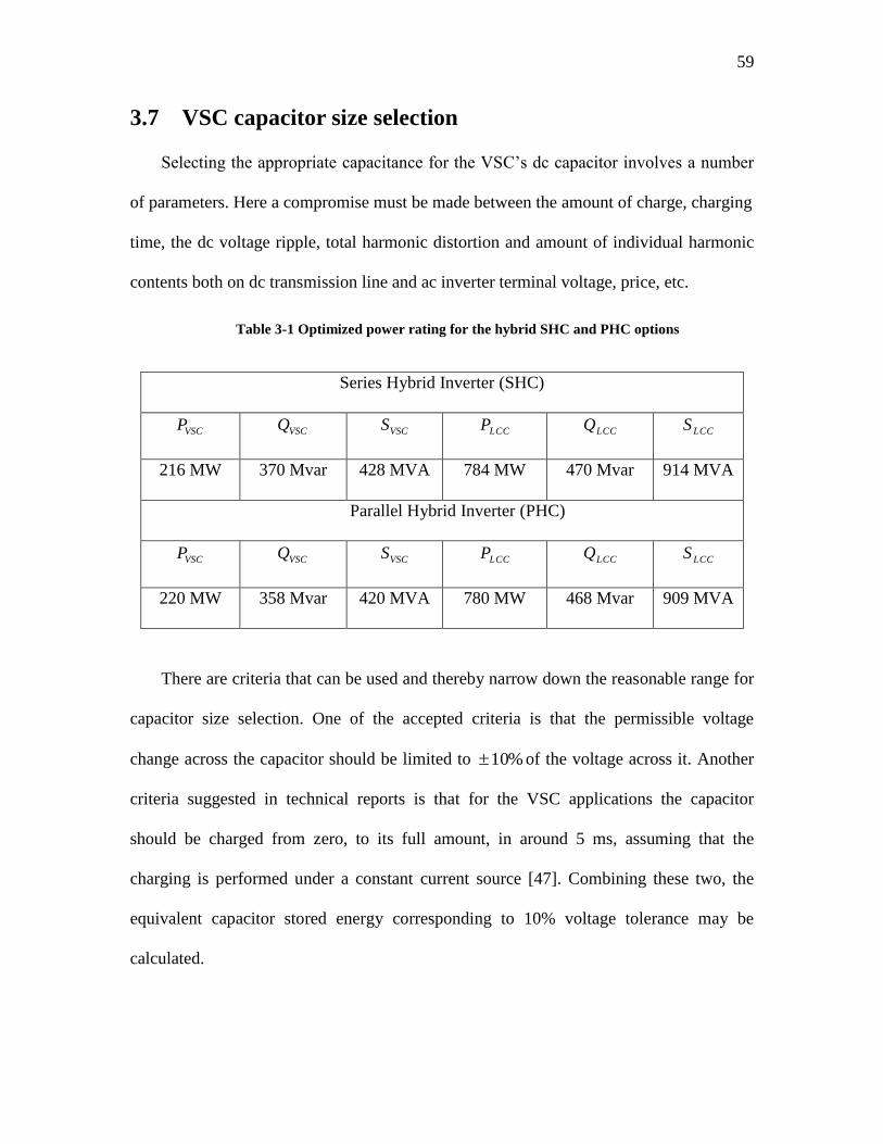
59
3.7 VSC capacitor size selection
Selecting the appropriate capacitance for the VSC‟s dc capacitor involves a number
of parameters. Here a compromise must be made between the amount of charge, charging
time, the dc voltage ripple, total harmonic distortion and amount of individual harmonic
contents both on dc transmission line and ac inverter terminal voltage, price, etc.
Table 3-1 Optimized power rating for the hybrid SHC and PHC options
Series Hybrid Inverter (SHC)
VSCP VSCQ
VSCS LCCP
LCCQ LCCS
216 MW 370 Mvar 428 MVA 784 MW 470 Mvar 914 MVA
Parallel Hybrid Inverter (PHC)
VSCP VSCQ VSCS LCCP LCCQ LCCS
220 MW 358 Mvar 420 MVA 780 MW 468 Mvar 909 MVA
There are criteria that can be used and thereby narrow down the reasonable range for
capacitor size selection. One of the accepted criteria is that the permissible voltage
change across the capacitor should be limited to %10 of the voltage across it. Another
criteria suggested in technical reports is that for the VSC applications the capacitor
should be charged from zero, to its full amount, in around 5 ms, assuming that the
charging is performed under a constant current source [47]. Combining these two, the
equivalent capacitor stored energy corresponding to 10% voltage tolerance may be
calculated.
60
Assume a 10% overvoltage, which is 108 kV *10%, or 10.8 kV (for the SHC). Also
assume that the charging takes place under constant current injection (2 KA from the dc
line) and the span of time is around 5 ms. Using the linear approximation tICV .)./1(
between voltage across a capacitor and the current going through it the capacitor size can
be estimated. Using these numbers and the given approximation the capacitor size of
around 1000 F can be attained. This value has been used for all of the system studies
performed here and no specific effort was made to optimize the VSC capacitor size,
though an appropriate capacitance is suggested based on optimized system response to
different working conditions using simulations.
3.8 Control objectives in hybrid design
The control strategy for the hybrid system is based on two control objectives:
Regulation of the terminal voltage of the hybrid converters‟ ac busbar,
Achieving the ordered power in all working conditions, within the full reactive
power range required for voltage regulation. This power flows from hybrid
inverter toward inverter terminal and normally would be equal to the rated (1 p.u.)
in steady state conditions.
The hybrid inverter has been designed so that it when delivers one (1) p.u. of real
power to the ac system the terminal operates at unity power factor. In all other conditions,
keeping the terminal at one p.u. necessitates reactive power flow into, or out of the
inverter terminal. The controllers for both hybrid options are a combination of the
controls for the conventional LCC, and VSC converters.
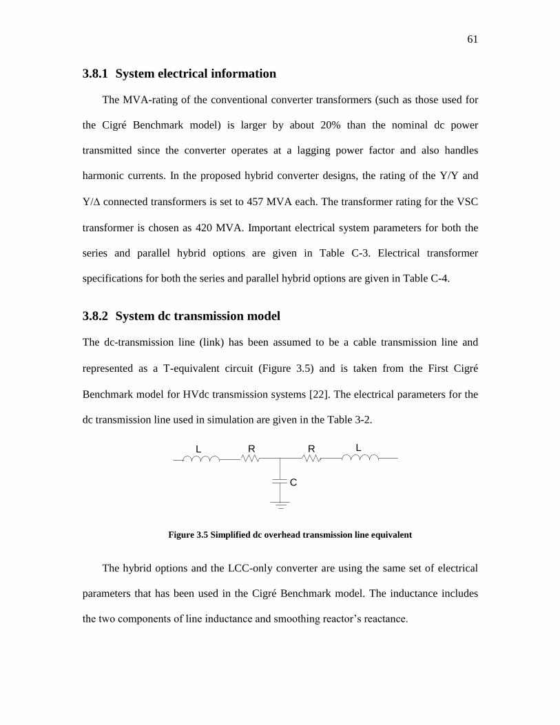
61
3.8.1 System electrical information
The MVA-rating of the conventional converter transformers (such as those used for
the Cigré Benchmark model) is larger by about 20% than the nominal dc power
transmitted since the converter operates at a lagging power factor and also handles
harmonic currents. In the proposed hybrid converter designs, the rating of the Y/Y and
Y/ connected transformers is set to 457 MVA each. The transformer rating for the VSC
transformer is chosen as 420 MVA. Important electrical system parameters for both the
series and parallel hybrid options are given in Table C-3. Electrical transformer
specifications for both the series and parallel hybrid options are given in Table C-4.
3.8.2 System dc transmission model
The dc-transmission line (link) has been assumed to be a cable transmission line and
represented as a -equivalent circuit (Figure 3.5) and is taken from the First Cigré
Benchmark model for HVdc transmission systems [22]. The electrical parameters for the
dc transmission line used in simulation are given in the Table 3-2.
L R R L
C
Figure 3.5 Simplified dc overhead transmission line equivalent
The hybrid options and the LCC-only converter are using the same set of electrical
parameters that has been used in the Cigré Benchmark model. The inductance includes
the two components of line inductance and smoothing reactor‟s reactance.
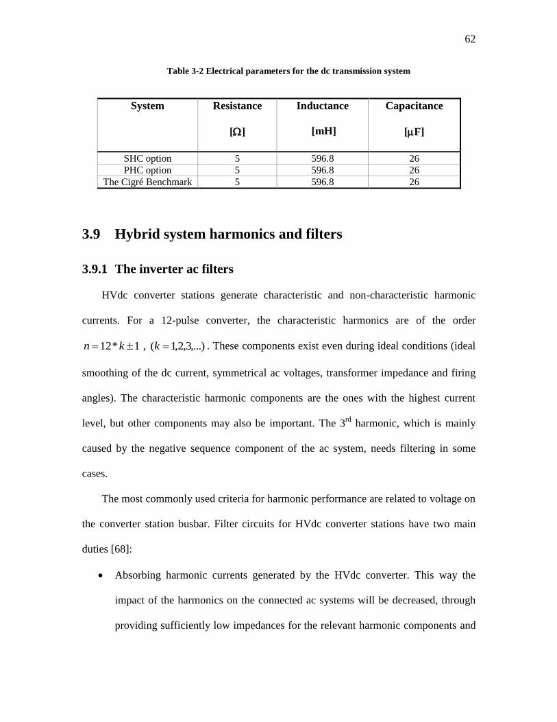
62
Table 3-2 Electrical parameters for the dc transmission system
System Resistance
[]
Inductance
[mH]
Capacitance
[F]
SHC option 5 596.8 26
PHC option 5 596.8 26
The Cigré Benchmark 5 596.8 26
3.9 Hybrid system harmonics and filters
3.9.1 The inverter ac filters
HVdc converter stations generate characteristic and non-characteristic harmonic
currents. For a 12-pulse converter, the characteristic harmonics are of the order
,...)3,2,1( , 1*12 kkn . These components exist even during ideal conditions (ideal
smoothing of the dc current, symmetrical ac voltages, transformer impedance and firing
angles). The characteristic harmonic components are the ones with the highest current
level, but other components may also be important. The 3rd
harmonic, which is mainly
caused by the negative sequence component of the ac system, needs filtering in some
cases.
The most commonly used criteria for harmonic performance are related to voltage on
the converter station busbar. Filter circuits for HVdc converter stations have two main
duties [68]:
Absorbing harmonic currents generated by the HVdc converter. This way the
impact of the harmonics on the connected ac systems will be decreased, through
providing sufficiently low impedances for the relevant harmonic components and
63
reducing the harmonic voltages to an acceptable level. Harmonic pollution may
cause premature aging and degradation of performance (even misoperation) for
various components in a power system. The allowable harmonic pollution is
governed by standards [68].
Supplying reactive power for compensating the reactive demand of the LCC
converter, which in case of hybrid converters this is not as important as in the
LCC, because part of the LCC‟s reactive power can be generated by the VSC.
A commonly used criterion for all harmonic components up to 49th
order is as follows:
Individual harmonic voltage distortion of order i ( iD ) is limited to 1% of the
fundamental ac busbar voltage [68].
Total geometric sum ( rmsD ) of individual voltage distortion ( iD ) is limited to 2%
[68].
The telephone interference factor (TIF), which is determined from weighted
individual harmonic factors, is not relevant in many cases because modern digital
telephone systems are not sensitive to harmonic interferences.
The distortion level on the ac busbar depends also on the grid impedance, as well as
the filter impedance. Because of that, in practice an adequate impedance model of the
grid for all relevant harmonics is required in order to optimize the filter design. The
detuning caused by ac network frequency deviations and component parameter deviations
must also be considered when selecting the bandwidth of the filters.
Using a 12-pulse LCC converter and Y / YY transformer connections for both
hybrid converter options, the most important harmonics remained from LCC converters
are typically tuned to the 11th
, 13th
,23rd
,25th
and 29th
order.
64
Here singly tuned filters are assumed, as is the case in many existing systems,
although new systems usually employ multiply-tuned filters [97] which are typically less
expensive. However, the selection of the single tuned filters used here does not affect the
essential behavior of the system.
Selecting a carrier frequency at 27 0f for switching the IGBT switches in VSC
converter causes the harmonics at this frequency to be suppressed because of the
cancellation in the LCC transformers; however, its sidebands (25th
and 29th
components)
need dedicated filters. Based on that, the main filters used in both of the hybrid inverter
side are 11th
, 13th
, 23rd
, 25th
, 29th
and 55th
orders.
As explained in section 3.6.1 to satisfy the minimum THD and individual harmonic
current ( iD ) requirements, the minimum required filters for SHC and PHC options are
103 Mvar and 110 Mvar, respectively. Smaller size filters cannot satisfy the THD nor the
individual harmonic requirements set by the IEEE standards [68]. Also low Mvar filters
offer narrow bandwidth which may not be sufficient to cover normal system frequency
fluctuations. On the other hand, if the Mvar rating of the filters is too high, large transient
overvoltages can occur upon load rejection, or in similar transient events. The selected
filters and their values target the above mentioned frequencies and satisfy the bandwidth
requirement for detuning, and yet give acceptable transient response.
Table 3-3 specifies total reactive power generation capacity for the hybrid options
and for the LCC-only option. Each of the singly-tuned band-pass filters used in hybrid
structures consists of a simple series electrical connection of a resistor, inductor, and
capacitor. The totalP refers to total inverter active power. In Appendix B, filter frequency
response for the series and parallel hybrid systems, and the impedance plots are given.
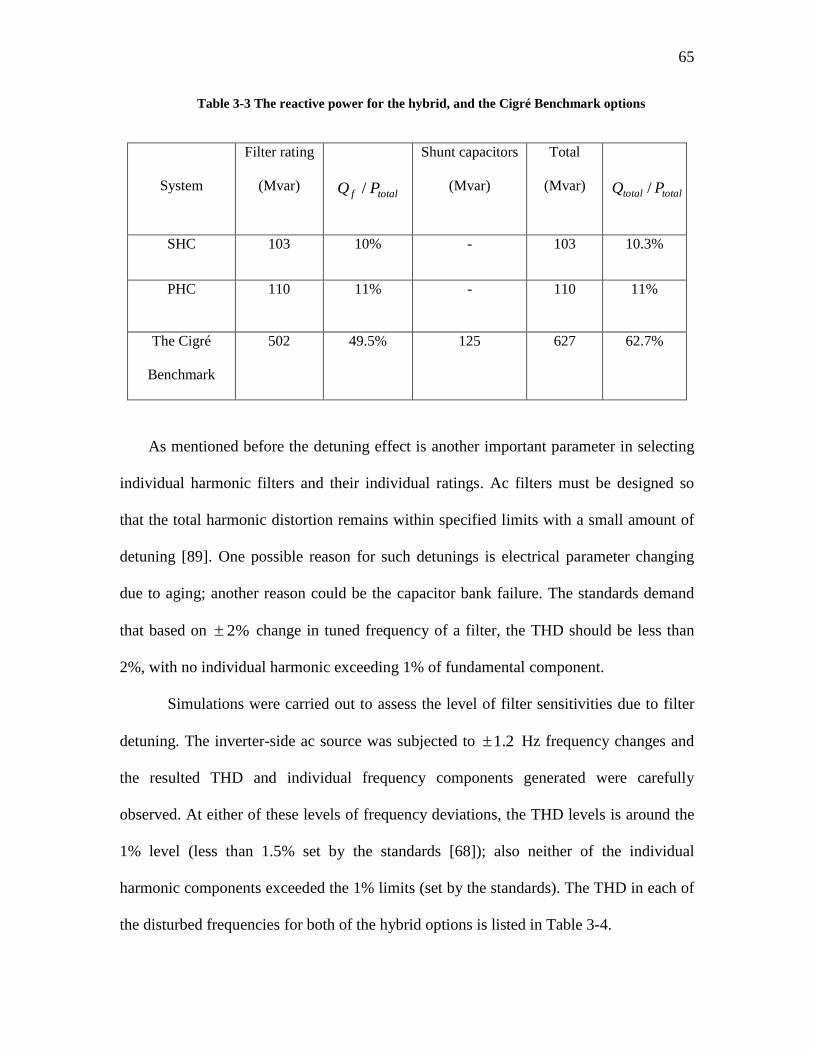
65
Table 3-3 The reactive power for the hybrid, and the Cigré Benchmark options
System
Filter rating
(Mvar)
totalf PQ /
Shunt capacitors
(Mvar)
Total
(Mvar)
totaltotal PQ /
SHC 103 10% - 103 10.3%
PHC 110 11% - 110 11%
The Cigré
Benchmark
502 49.5% 125 627 62.7%
As mentioned before the detuning effect is another important parameter in selecting
individual harmonic filters and their individual ratings. Ac filters must be designed so
that the total harmonic distortion remains within specified limits with a small amount of
detuning [89]. One possible reason for such detunings is electrical parameter changing
due to aging; another reason could be the capacitor bank failure. The standards demand
that based on 2% change in tuned frequency of a filter, the THD should be less than
2%, with no individual harmonic exceeding 1% of fundamental component.
Simulations were carried out to assess the level of filter sensitivities due to filter
detuning. The inverter-side ac source was subjected to 1.2 Hz frequency changes and
the resulted THD and individual frequency components generated were carefully
observed. At either of these levels of frequency deviations, the THD levels is around the
1% level (less than 1.5% set by the standards [68]); also neither of the individual
harmonic components exceeded the 1% limits (set by the standards). The THD in each of
the disturbed frequencies for both of the hybrid options is listed in Table 3-4.
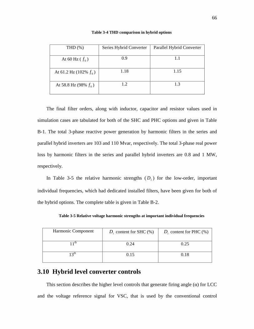
66
Table 3-4 THD comparison in hybrid options
THD (%) Series Hybrid Converter Parallel Hybrid Converter
At 60 Hz ( 0f ) 0.9 1.1
At 61.2 Hz (102% 0f ) 1.18 1.15
At 58.8 Hz (98% 0f ) 1.2 1.3
The final filter orders, along with inductor, capacitor and resistor values used in
simulation cases are tabulated for both of the SHC and PHC options and given in Table
B-1. The total 3-phase reactive power generation by harmonic filters in the series and
parallel hybrid inverters are 103 and 110 Mvar, respectively. The total 3-phase real power
loss by harmonic filters in the series and parallel hybrid inverters are 0.8 and 1 MW,
respectively.
In Table 3-5 the relative harmonic strengths ( iD ) for the low-order, important
individual frequencies, which had dedicated installed filters, have been given for both of
the hybrid options. The complete table is given in Table B-2.
Table 3-5 Relative voltage harmonic strengths at important individual frequencies
Harmonic Component iD content for SHC (%) iD content for PHC (%)
11th 0.24 0.25
13th 0.15 0.18
3.10 Hybrid level converter controls
This section describes the higher level controls that generate firing angle (α) for LCC
and the voltage reference signal for VSC, that is used by the conventional control
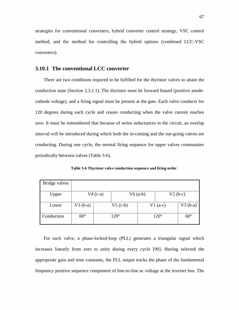
67
strategies for conventional converters, hybrid converter control strategy, VSC control
method, and the method for controlling the hybrid options (combined LCC-VSC
converters).
3.10.1 The conventional LCC converter
There are two conditions required to be fulfilled for the thyristor valves to attain the
conduction state (Section 2.3.1.1). The thyristor must be forward biased (positive anode-
cathode voltage), and a firing signal must be present at the gate. Each valve conducts for
120 degrees during each cycle and ceases conducting when the valve current reaches
zero. It must be remembered that because of series inductances in the circuit, an overlap
interval will be introduced during which both the in-coming and the out-going valves are
conducting. During one cycle, the normal firing sequence for upper valves commutates
periodically between valves (Table 3-6).
Table 3-6 Thyristor valve conduction sequence and firing order
Bridge valves
Upper V4 (c-a) V6 (a-b) V2 (b-c)
Lower V3 (b-a) V5 (c-b) V1 (a-c) V3 (b-a)
Conduction 60° 120° 120° 60°
For each valve, a phase-locked-loop (PLL) generates a triangular signal which
increases linearly from zero to unity during every cycle [90]. Having selected the
appropriate gain and time constants, the PLL output tracks the phase of the fundamental
frequency positive sequence component of line-to-line ac voltage at the inverter bus. The
68
PLL output can thus be used as an accurate reference for generating the firing pulses as
discussed in [90].
These firing signals are sent to each valve when its triangular signal becomes larger
than the firing signal. The mentioned ordering sequence is managed internally by a
standard PSCAD/EMTDC converter model. This block issues the firing commands to
valves of the LCC converters [12].
3.10.2 The VSC converter
The IGBT valves have identical positioning order and firing sequence as mentioned
for the thyristor valves. The triggering pulses for switches are based on the PWM method
(Section 2.5) where a triangular carrier is compared to the three phase sinusoidal
reference voltages measured at ac inverter terminal voltages. The main difference
between thyristor and IGBT switching operation is that the former will be switched only
once in a cycle and conducts for 120 degrees while the latter may be turned on and off
repeatedly in each cycle, with 27 times the system base frequency ( 0f ) of 60 Hz, based
on the outcome of compared signal levels.
3.10.3 Traditional control strategies for conventional converters
The majority of existing HVdc-schemes operate in current control mode at the rectifier
side and at extinction angle (γ) control mode at the inverter side [4]. To ensure successful
firing, a minimum firing angle (α) of about 5 is required at the rectifier side, so that a
sufficient positive voltage across the valve exists at the time of firing. For better control
flexibility it is preferred to have a steady-state firing angle within a tolerance band around
69
15 , ensuring that the reactive power consumption at the inverter is kept at a minimum
level without causing commutation failure.
Decreasing the extinction angle (γ) will cause an improvement in inverter power
factor but, on the other hand, the probability of commutation failure increases as this
angle decreases, leaving only a narrow tolerance band of 2015 for the steady-state
firing angle.
It is clear that there is a trade-off between low and high extinction angles (γ) at the
inverter side, which brings low reactive power consumption, and low risk of
commutation failure, respectively. The voltage source in the inverter ac network is
adjusted so that the extinction angle becomes 15 and 20 for the SHC and PHC inverter
options, respectively. Knowing that the voltage control through adjusting the angle order
has limitations, or in cases that firing angle and the extinction angle (γ) exceed their
tolerance band for more than a few seconds [91], the slow tap-changer control at the
converter transformers may be used to keep these angles within their desired range. In
this research the tap-changer control has not been considered because its response time
(around 1 second) falls beyond the transient time scale.
When the inverter operating in extinction angle (γ) control mode, the higher the line
capacitance, the more difficult it would be to operate. When a disturbance causes a
reduction in the ac inverter bus voltage the diV (inverter dc voltage, measured on the
converter side of the smoothing inductor), the negative resistance characteristic of the
inverter causes the voltage across transformer leakage reactance, and the extinction angle
( ) to decrease, which increases the chance of commutation failure [92]. This reaction is
more pronounced when there is no fast-acting ac voltage control device close to the
70
inverter bus. The negative resistance is not much evident in the hybrid inverter options
because of different dominant control mode chosen for the inverter side.
3.11 Hybrid converter control strategy
The nominal control strategy at the rectifier end for both of the hybrid options, based
on control objectives (Section 3.8) for hybrid converters, is power control outer loop with
a current control inner loop. However, a backup voltage control mode becomes necessary
for the PHC option. The description of the control strategies for the VSC and LCC
converters for the two options are presented below.
3.12 Decoupled vs. direct control of VSC converters
In power systems it is desirable to have independent control on real and reactive
power changes. Here, the two conventional methods used to control VSC converters are
discussed.
3.12.1 Decoupled method
In order to make real and reactive power changes independent the decoupled method
is often used [84]. The complete general schematic for dq-based VSC control has been
illustrated in Figure 3.6. All signals are referenced as direct and quadrature components.
The direct (d-axis) component is in phase with the positive sequence phase of voltage and
the q-axis is in quadrature with respect to d-axis.
VSC control has three parts. In the first part, the reference and measured dc voltages
of the VSC capacitor ( *SC ,VdcV and VSCdcV , ) are used to issue the di reference signal (
*di ).
This signal determines the real power reference command at VSC converter. The rms
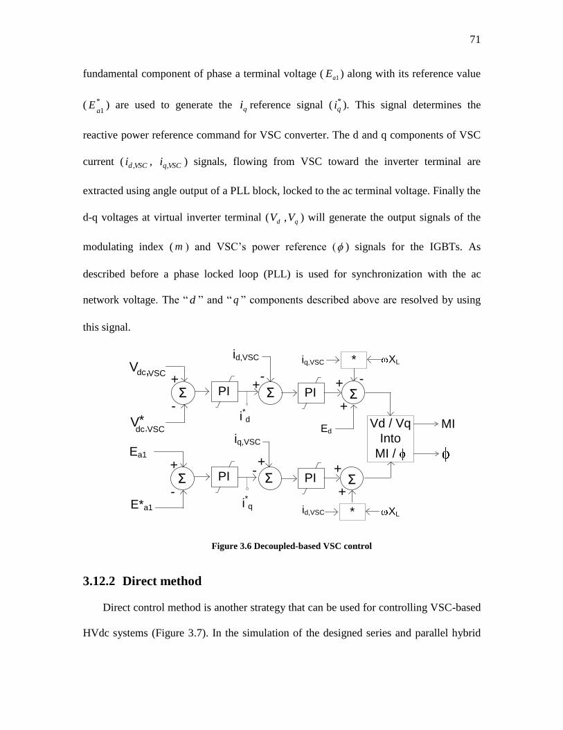
71
fundamental component of phase a terminal voltage ( 1aE ) along with its reference value
( *
1aE ) are used to generate the qi reference signal ( *
qi ). This signal determines the
reactive power reference command for VSC converter. The d and q components of VSC
current ( VSCdi , , VSCqi , ) signals, flowing from VSC toward the inverter terminal are
extracted using angle output of a PLL block, locked to the ac terminal voltage. Finally the
d-q voltages at virtual inverter terminal ( qd VV , ) will generate the output signals of the
modulating index ( m ) and VSC‟s power reference ( ) signals for the IGBTs. As
described before a phase locked loop (PLL) is used for synchronization with the ac
network voltage. The “ d ” and “ q ” components described above are resolved by using
this signal.
+
-Σ
+Vdc,VSC
V*dc,VSC
-
Σ+
i*d
id,VSC
Σ
XL
+
+ -
Ed
+
-Σ
+ +
Σ-
i*q
iq,VSC
Σ
id,VSC
+
+
Ea1
E*a1
Vd / Vq
Into
MI /
MI
iq,VSC *
* XL
PI
PI
PI
PI
Figure 3.6 Decoupled-based VSC control
3.12.2 Direct method
Direct control method is another strategy that can be used for controlling VSC-based
HVdc systems (Figure 3.7). In the simulation of the designed series and parallel hybrid
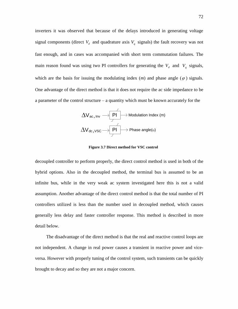
72
inverters it was observed that because of the delays introduced in generating voltage
signal components (direct dV and quadrature axis qV signals) the fault recovery was not
fast enough, and in cases was accompanied with short term commutation failures. The
main reason found was using two PI controllers for generating the dV and qV signals,
which are the basis for issuing the modulating index (m) and phase angle ( ) signals.
One advantage of the direct method is that it does not require the ac side impedance to be
a parameter of the control structure – a quantity which must be known accurately for the
Modulation Index (m)
Phase angle( )
Vac, Inv
Vdc,VSC
PI
PI
Figure 3.7 Direct method for VSC control
decoupled controller to perform properly, the direct control method is used in both of the
hybrid options. Also in the decoupled method, the terminal bus is assumed to be an
infinite bus, while in the very weak ac system investigated here this is not a valid
assumption. Another advantage of the direct control method is that the total number of PI
controllers utilized is less than the number used in decoupled method, which causes
generally less delay and faster controller response. This method is described in more
detail below.
The disadvantage of the direct method is that the real and reactive control loops are
not independent. A change in real power causes a transient in reactive power and vice-
versa. However with properly tuning of the control system, such transients can be quickly
brought to decay and so they are not a major concern.
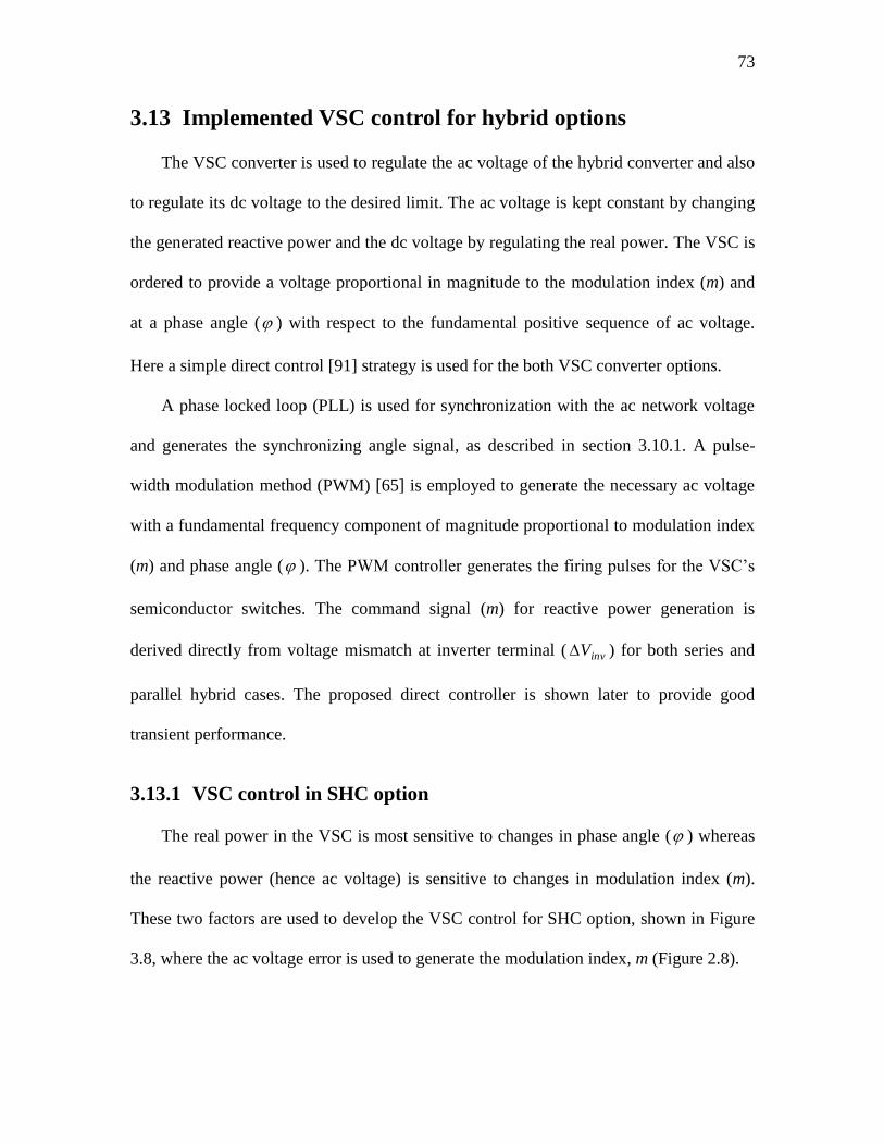
73
3.13 Implemented VSC control for hybrid options
The VSC converter is used to regulate the ac voltage of the hybrid converter and also
to regulate its dc voltage to the desired limit. The ac voltage is kept constant by changing
the generated reactive power and the dc voltage by regulating the real power. The VSC is
ordered to provide a voltage proportional in magnitude to the modulation index (m) and
at a phase angle ( ) with respect to the fundamental positive sequence of ac voltage.
Here a simple direct control [91] strategy is used for the both VSC converter options.
A phase locked loop (PLL) is used for synchronization with the ac network voltage
and generates the synchronizing angle signal, as described in section 3.10.1. A pulse-
width modulation method (PWM) [65] is employed to generate the necessary ac voltage
with a fundamental frequency component of magnitude proportional to modulation index
(m) and phase angle ( ). The PWM controller generates the firing pulses for the VSC‟s
semiconductor switches. The command signal (m) for reactive power generation is
derived directly from voltage mismatch at inverter terminal ( invV ) for both series and
parallel hybrid cases. The proposed direct controller is shown later to provide good
transient performance.
3.13.1 VSC control in SHC option
The real power in the VSC is most sensitive to changes in phase angle ( ) whereas
the reactive power (hence ac voltage) is sensitive to changes in modulation index (m).
These two factors are used to develop the VSC control for SHC option, shown in Figure
3.8, where the ac voltage error is used to generate the modulation index, m (Figure 2.8).
74
Note that adjusting the dc capacitor voltage requires the input or output of real
power, and this adjustment is achieved through the control of phase angle, as described
above. In this figure invacV , , VSCdcV , and VSCdcI , refer to inverter ac voltage, VSC dc
voltage, and current, respectively. The “starred” values refer to their corresponding
reference values. For SHC option these reference values are 230 kV, 108 kV, and 2 kA,
and for PHC option these are 230 kV, 500 kV and 0.44 kA, respectively (Table 3-2).
Phase angle (φ)
Vac,Inv
+
-Σ
V*ac,Inv
Vdc,VSC
+
-Σ
V*dc,VSC
-
+
H
L
KP+KI/s
H
L
KP+KI/s
Modulation index (m)
Figure 3.8 VSC converter controls for the SHC option
3.13.2 VSC control in PHC option
As in the series converter case, the modulation index signal (m) which commands the
IGBTs is generated based on the error in the ac inverter terminal voltage of the PHC
converter. In normal working conditions, with the VSC‟s dc voltage being on the rated
(reference) value, the VSC‟s dc current mismatch will generate an error signal which is in
proportion to the phase angle ( ) (Figure 3.9(a)). Using smooth transition method
(Section 4.7), the lower PI controllers can be substituted with only one (Figure 3.9(b)).
The current reference for VSC is a percentage of the inverter current order (0.22) and
is already specified in section 3.6.
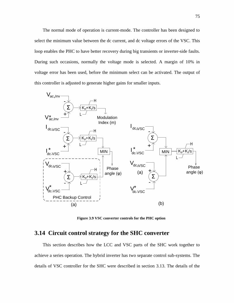
75
The normal mode of operation is current-mode. The controller has been designed to
select the minimum value between the dc current, and dc voltage errors of the VSC. This
loop enables the PHC to have better recovery during big transients or inverter-side faults.
During such occasions, normally the voltage mode is selected. A margin of 10% in
voltage error has been used, before the minimum select can be activated. The output of
this controller is adjusted to generate higher gains for smaller inputs.
Vac,Inv
PHC Backup Control
+
-Σ
V*ac,Inv
Vdc,VSC
+
-Σ
V*dc,VSC
-
-
+
H
L
KP+KI/s
H
L
KP+KI/s
MIN
Idc,VSC
+-Σ
I *dc,VSC
+
H
L
KP+KI/s
Phase
angle (φ)
Modulation
Index (m)
Vdc,VSC
+
-Σ
V*dc,VSC
-
+
H
L
KP+KI/sMIN
Idc,VSC
+-Σ
I *dc,VSC
+
(a)
(a)
(b)
Phase
angle (φ)
Figure 3.9 VSC converter controls for the PHC option
3.14 Circuit control strategy for the SHC converter
This section describes how the LCC and VSC parts of the SHC work together to
achieve a series operation. The hybrid inverter has two separate control sub-systems. The
details of VSC controller for the SHC were described in section 3.13. The details of the
76
LCC will be described later in section 3.14.1. The schematic control for the complete
SHC hybrid inverter/rectifier system is given in Appendix C-4.
Under normal conditions the dc voltage across LCC inverter is equal to its designed
dc voltage. The VSC converter keeps its dc voltage at its reference value. Hence rated
powers are generated in each of these two converters. Changing the power order at the
inverter terminal will cause a new LCC current order to be issued. The rectifier LCC
adjusts its output current to the new order. At the same time, both the LCC and VSC
converters try to adjust their output voltages. In steady state, the controllers will cause the
ordered power to be generated at the inverter side.
The series hybrid inverter scheme has been designed such that the VSC maintains the
inverter terminal voltage at one p.u., hence causing the inverter terminal to work in unity
power factor. Based on this power factor the voltage-control mode would be operational
during normal working conditions, which is a direct indication that ac voltage controller
is able to perform the requested control task appropriately.
When dealing with a very weak system, the extinction angle-control mode was
observed to be too oscillatory and difficult to control. As a result it was decided not to use
the control as the dominant control mode for the LCC inverterIn SHC option both the
and current-control modes are used as the backup modes.
In the modelled SHC option, only inverter operation of the hybrid converter was
considered. The rectifier was implemented as an LCC-only converter in the current-
control mode. From the inverter‟s ac terminal view, VSC delivers the complete reactive
power requested by the LCC inverter, which in fact may also be supplemented by extra
reactive power request from the ac system, depending on available rating [9]. Looking
77
from the dc side of the hybrid inverter, VSC plays a role in both active and reactive
power generation and voltage support. Due to VSC‟s role in real power generation, the
LCC inverter can be designed to have lower rating (Section 3.6).
3.14.1 Control of the LCC inverter for the SHC option
In the SHC option the conventional (LCC) part of inverter normally operates in
voltage control mode, reverting to current-control, or extinction angle ( control modes
at the boundaries. One boundary is when the dc current falls more than 10% (current
margin) below its set value.
Current control is implemented in rectifier side. In case the rectifier is unable to
control direct current then inverter must take over current control. The other boundary is
when the voltage control mode causes the extinction angle ( to fall below min , thereby
endangering the inverter operation. In such occasions the inverter would be forced to
operate in mode to avoid commutation failure.
Figure 3.10 depicts the LCC converter block diagram for the SHC option. In this
figure LCCdcV , and *,LCCdcV refer to the measured, and the reference dc voltage across the
LCC converter at the inverter side, respectively.
The rectifier current order is extracted from the terminal power error signal and LCC
inverter dc voltage. *,InvdcI and InvdcI , refer to the reference, and measured dc current at the
LCC inverter, respectively. InvdcI , is the same current that flows into the VSC converter.
* and refer to the reference, and measured extinction angles, respectively.
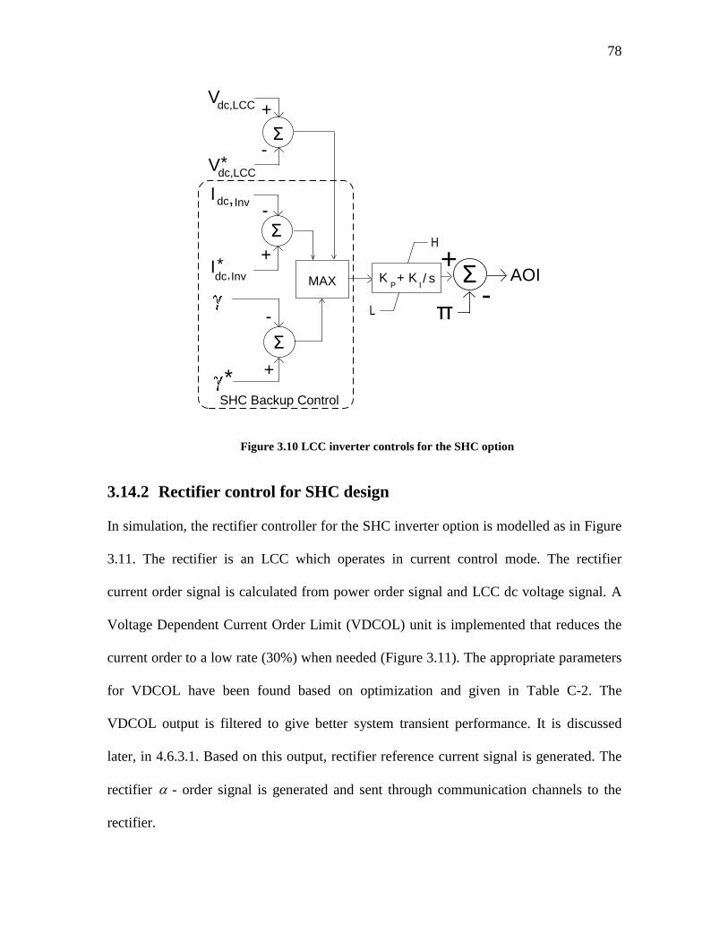
78
AOI
-Σ
+
π
SHC Backup Control
+-Σ
+-
Σ
-
+
MAX
+-Σ
+
Vdc,LCC
Vdc,LCC*
Idc,Inv
I*dc,Inv
*
H
L
KP+ K
I/ s
Figure 3.10 LCC inverter controls for the SHC option
3.14.2 Rectifier control for SHC design
In simulation, the rectifier controller for the SHC inverter option is modelled as in Figure
3.11. The rectifier is an LCC which operates in current control mode. The rectifier
current order signal is calculated from power order signal and LCC dc voltage signal. A
Voltage Dependent Current Order Limit (VDCOL) unit is implemented that reduces the
current order to a low rate (30%) when needed (Figure 3.11). The appropriate parameters
for VDCOL have been found based on optimization and given in Table C-2. The
VDCOL output is filtered to give better system transient performance. It is discussed
later, in 4.6.3.1. Based on this output, rectifier reference current signal is generated. The
rectifier - order signal is generated and sent through communication channels to the
rectifier.
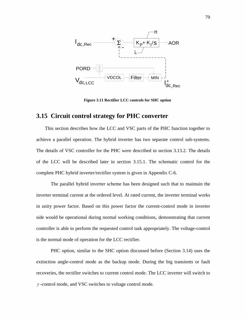
79
AOR
VDCOL
-
PORD
+ Idc,Rec
MIN Filter Vdc,
H
L
KP+ K
I/s
LCC * Idc,Rec
Figure 3.11 Rectifier LCC controls for SHC option
3.15 Circuit control strategy for PHC converter
This section describes how the LCC and VSC parts of the PHC function together to
achieve a parallel operation. The hybrid inverter has two separate control sub-systems.
The details of VSC controller for the PHC were described in section 3.13.2. The details
of the LCC will be described later in section 3.15.1. The schematic control for the
complete PHC hybrid inverter/rectifier system is given in Appendix C-6.
The parallel hybrid inverter scheme has been designed such that to maintain the
inverter terminal current at the ordered level. At rated current, the inverter terminal works
in unity power factor. Based on this power factor the current-control mode in inverter
side would be operational during normal working conditions, demonstrating that current
controller is able to perform the requested control task appropriately. The voltage-control
is the normal mode of operation for the LCC rectifier.
PHC option, similar to the SHC option discussed before (Section 3.14) uses the
extinction angle-control mode as the backup mode. During the big transients or fault
recoveries, the rectifier switches to current control mode. The LCC inverter will switch to
-control mode, and VSC switches to voltage control mode.
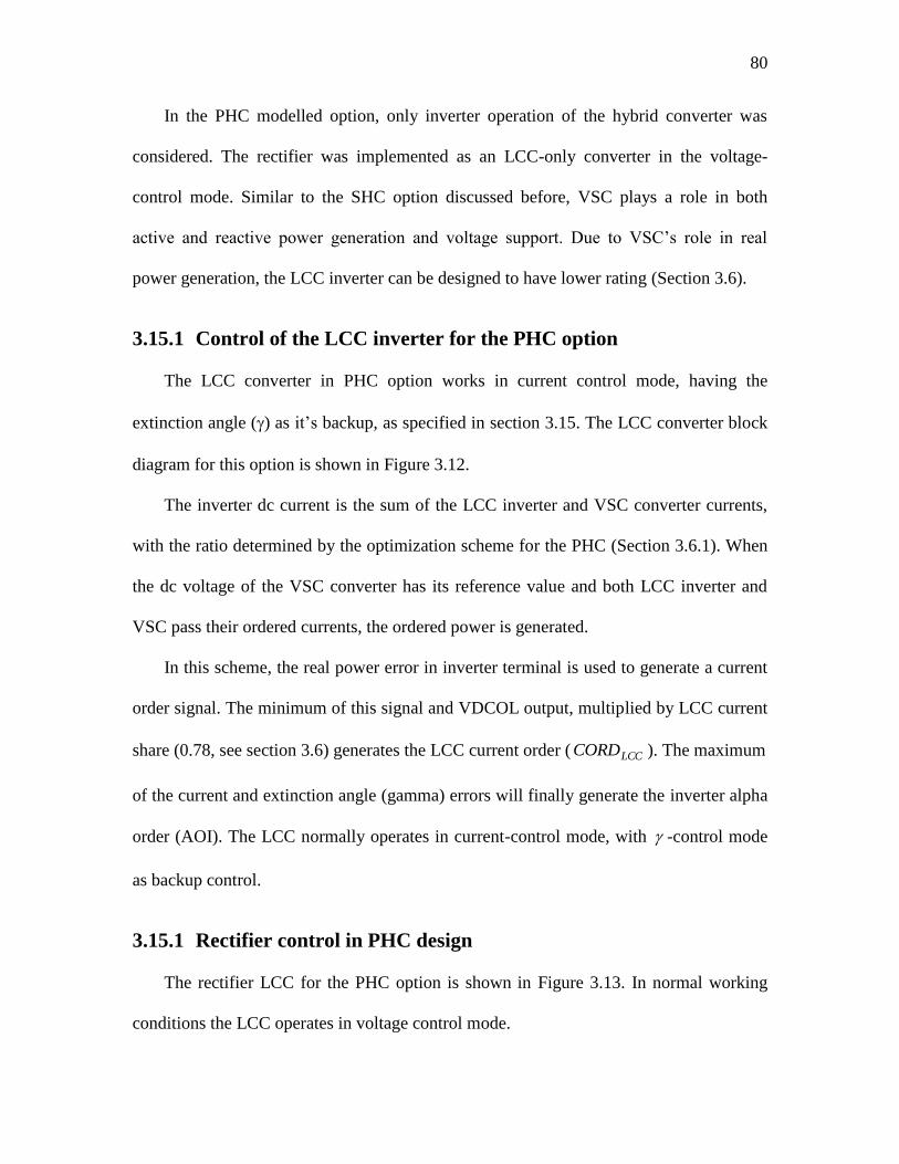
80
In the PHC modelled option, only inverter operation of the hybrid converter was
considered. The rectifier was implemented as an LCC-only converter in the voltage-
control mode. Similar to the SHC option discussed before, VSC plays a role in both
active and reactive power generation and voltage support. Due to VSC‟s role in real
power generation, the LCC inverter can be designed to have lower rating (Section 3.6).
3.15.1 Control of the LCC inverter for the PHC option
The LCC converter in PHC option works in current control mode, having the
extinction angle () as it‟s backup, as specified in section 3.15. The LCC converter block
diagram for this option is shown in Figure 3.12.
The inverter dc current is the sum of the LCC inverter and VSC converter currents,
with the ratio determined by the optimization scheme for the PHC (Section 3.6.1). When
the dc voltage of the VSC converter has its reference value and both LCC inverter and
VSC pass their ordered currents, the ordered power is generated.
In this scheme, the real power error in inverter terminal is used to generate a current
order signal. The minimum of this signal and VDCOL output, multiplied by LCC current
share (0.78, see section 3.6) generates the LCC current order ( LCCCORD ). The maximum
of the current and extinction angle (gamma) errors will finally generate the inverter alpha
order (AOI). The LCC normally operates in current-control mode, with -control mode
as backup control.
3.15.1 Rectifier control in PHC design
The rectifier LCC for the PHC option is shown in Figure 3.13. In normal working
conditions the LCC operates in voltage control mode.
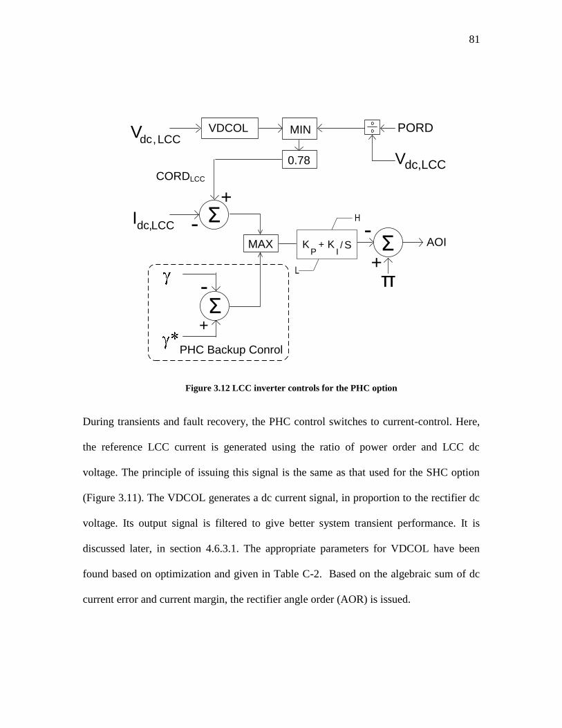
81
MIN
AOI
-
MAX-
π+
+
Σ
Σ
+
-Σ
-
PHC Backup Conrol
Idc,LCC
VDCOL
0.78
CORDLCC
Vdc,LCCPORD
Vdc,LCC
H
L
KP
+ KI/ S
Figure 3.12 LCC inverter controls for the PHC option
During transients and fault recovery, the PHC control switches to current-control. Here,
the reference LCC current is generated using the ratio of power order and LCC dc
voltage. The principle of issuing this signal is the same as that used for the SHC option
(Figure 3.11). The VDCOL generates a dc current signal, in proportion to the rectifier dc
voltage. Its output signal is filtered to give better system transient performance. It is
discussed later, in section 4.6.3.1. The appropriate parameters for VDCOL have been
found based on optimization and given in Table C-2. Based on the algebraic sum of dc
current error and current margin, the rectifier angle order (AOR) is issued.
82
MAX
+ -
-
AOR
I dc , Rec
CMARG
MIN
Σ
PHC Backup Control
+
-
Σ
I * dc,Rec V dc , Rec VDCOL Filter
V dc , Rec
V * dc,Rec
H
L
KP
+ KI/ S
Figure 3.13 LCC controls for rectifier in PHC option
Chapter 4: Hybrid Converter Transmission
System Performance
4.1 Introduction
A well-designed HVdc system should react rapidly to set-point changes, while
demonstrating reasonable fast recovery from system faults. The objective of this chapter
is to investigate the feasibility and suitability of different hybrid inverter topologies in an
HVdc transmission system scheme, terminating into a very weak ac network. As will be
pointed out in this chapter, the traditional control method of LCC systems needs some
modifications to appropriately host a VSC converter. These modifications for both the
series (SHC) and parallel (PHC) hybrid inverters will be first discussed in this chapter.
The hybrid system behavior under these control methods will then be evaluated and
compared to the LCC-only inverter scheme.
In order to investigate the performance of the two proposed SHC- and PHC-based
hybrid HVdc transmission systems described in the previous chapter PSCAD/EMTDC
simulation software tool will be used. System behavior will be studied under steady state,
by subjecting the HVdc converters to various operating point changes, transient behavior
(small and large signal changes) and system faults. The results of performance
comparison between the hybrid options and the Cigré Benchmark model will be covered
in this chapter.
The absence of a reported HVdc system that is capable of operating under very low
SCRs makes the evaluation and performance comparison of the proposed hybrid
converter HVdc systems difficult. As a trusted benchmark in HVdc systems, the First
84
Cigré Benchmark model for HVdc control studies (the Cigré Benchmark in this text) was
selected as a test bed (Section 2.9).
Because the inverter side of the hybrid options are designed to operate under SCR =
1 and the Cigré Benchmark model for SCR = 2.5, comparing their performances cannot
be accomplished based on equal system parameters and conditions. As a conventional
LCC-based converter cannot operate under SCR = 1, in this research it is assumed that
the original SCR of Cigré Benchmark model inverter-side is modified using reactive
power generators such as fixed capacitors or synchronous condenses. The modification
causes the effective short circuit (ESCR) of the Cigré Benchmark inverter system to be
comparable with the hybrid converters under investigation. The behavior of the proposed
SHC- and PHC-based HVdc systems was investigated by subjecting the HVdc converters
to various operating point changes and system faults. Other modifications made to the
Cigré Benchmark case are discussed below.
4.1.1 Modifications in inverter configuration
The principal modification was made to the configuration of the inverter side of the
Cigré Benchmark model. For the SHC option, the conventional LCC inverter was
replaced with a series connection of a 12-pulse conventional LCC converter and a 2-level
VSC converter. For the PHC case the 2-level VSC converter was added as a shunt to the
12-pulse LCC converter. Control strategy was modified as needed. The controller
parameters were optimized for an overall good performance [93], not for any particular
single disturbance event (Chapter 3).
85
4.1.2 Modifications in inverter electrical specifications
The Short Circuit Ratio (SCR) at the ac inverter terminal was lowered considerably,
to investigate the hybrid‟s additional capability of operating at very low SCRs. Both of
the designed hybrid converters operate into a very weak ac system (SCR = 1). A
conventional LCC converter would typically not be able to operate when connected to
such a weak system. If we use the same amount of total reactive power generated in a
conventional LCC (such as Cigré Benchmark model) with SCR =1, the effective short
circuit ratio (ESCR) is as low as 0.23. This number is based on the real power generation
of LCC-inverter in hybrid option. Hence, for the comparison, the model for the LCC-only
option includes an ac network with SCR = 2.5 (ESCR = 1.9, after accounting for ac filters
and fixed capacitors on the busbar). This larger SCR could be considered to arise from
additional compensation using synchronous condensers as would be necessary to enable
the use of a conventional converter.
The power rating was kept the same, but at the inverter side the original LCC‟s
power capacity was reduced to provide some room to the newly added VSC inverter. The
relative ratings were selected as discussed in section 3.6.
4.1.3 Modifications in rectifier side
The rectifier side for both hybrid options is assumed to be a conventional LCC
converter identical to the Cigré Benchmark model. For the PHC option, a back-up current
controller was added to the control system. The controller parameters were optimized for
an overall good performance [93], not for any particular single disturbance event
(Chapter 3).
86
4.2 Method / tools for system study
To fully analyze the proposed hybrid HVdc systems an exact mathematical model of
both the LCC and VSC converters is needed. Then these models must be integrated into a
single mathematical model describing the integrated system. This model enables the user
to perform a small signal analysis, which will only be valid for small changes around
system‟s operating point and will indicate the validity of selected control parameters
around this point. The complexity and extensiveness of the composite integrated system
(series, or parallel hybrid converter) prevents the integration of separate mathematical
models for each of the two converter types into a single model. Frequency conversion
through ac-dc converters, discontinuous and non-linear nature of signal transfer through
converters, complexity of interaction equations between ac-dc variables and complexity
of phase locked loop (PLL) modeling will add to the complexities.
On the other hand, disruption of the normal switching sequence after a fault incident
especially during commutation failure periods and shortly after it, will lead to
considerable waveform distortion of the commutating voltage wave shapes, making the
problem not suitable for small signal analysis.
An appropriate tool that can be used as an alternative in such cases is to perform a
complete simulation-based study. Expected benefits of digital time-domain simulations
are as follows:
Ability to reproduce system performance with highest realistic degree of
complexity that is desired.
87
Investigating system fault modes and predicting the important parameters such as
over-voltage and over-current stress on energy storage elements and switching
elements at system, and at component-level.
Achieving realistic estimate on recovery time for an HVdc system, following a
disturbance
Having a “visual image” of system behavior under different working conditions
Providing the basis for protection requirements in a real HVdc system, if system
parameters are known
However time domain solution has the following disadvantages:
Methods for stability analyses such as eigenvalue approach which provide a “big
picture” understanding are not possible
It is time consuming to conduct extensive parametric studies
Based on the above explanations the mathematical method is not an option. Here, the
numerical simulation on an electromagnetic transients solver was chosen to assess the
behavior of the system and a trusted power system simulation tool, PSCAD/EMTDC,
was selected and used to conduct all aspects of model implementation, carry out
extensive simulation studies and assessing the overall HVdc system behavior. PSCAD /
EMTDC has proved instrumental in implementing the different aspects of power system
studies in general. It provides a powerful resource for assessing the proposed hybrid
HVdc systems in the power network.
In this research an attempt was made for not to resort to complicated control
strategies and the conventional closed-loop structure control has been used instead, trying
to keep the control system as simple as possible.
88
4.3 Hybrid system development steps
A hybrid converter model was developed using the Cigré Benchmark model as the
starting point (Section 3.6). Based on the power rating and voltages (ac and dc) of this
model the two SHC and PHC hybrid models were developed. To select the appropriate
power, voltage and current ratings, an optimization process was employed (Section
3.6.1).
A realistic reactive power demand for the LCC inverter and for the rating of the
harmonic filters is assumed. Based on these assumptions, the specifications for hybrid
inverter converters are derived. To do so, the mentioned optimization procedure was
used. As the last stage, the transformer ratings for VSC and LCC converter are calculated
(Appendix D.3). When simulating the designed systems, if total and/or individual
harmonic content of the inverter terminal ac voltage does not meet the standard levels, it
can be concluded that the total, and/or possibly some of the individual reactive power
rating of harmonic filters must be revised. If the total filter reactive power generation is
changed, the VSC / LCC inverter power ratings must be re-allocated. The whole design
process must be repeated until the appropriate voltage and current rating, and acceptable
harmonic levels are achieved. At this stage, the system operating point can be derived
(Appendix A).
As mentioned before, simple PI controllers have been employed in both of the hybrid
options. Because of the significant weakness of the selected ac inverter side of the
designed hybrid options, a customized sequence for start-up had to be implemented.
89
4.4 Parameter tuning
The recovery performance for any type of fault (close-in, or remote) depends on a
number of factors, such as ac system strength, dc system characteristics and controller
settings. In order for the HVdc schemes to demonstrate good performance for all types of
dynamic changes (faults or disturbances) the controllers need to be carefully tuned.
Fast recovery within 150 ms after the fault clearance is desirable for most normal
HVdc systems. SHC option can satisfy this requirement through fine tuning of control
parameters, discussed in the following section.
In case of the PHC option, achieving 150 ms recovery time proved to be
impractical, as discussed in section 4.8.5.1. To avoid a chain of sequences leading to
commutation failure in LCC-converter, and possible successive commutation failures in
PHC LCC converter, the power recovery speed needs to be reduced. Through multiple
simulation runs it was found out that around 450-500 ms recovery speed is the fastest
achievable for this option.
In the simulations the control system parameters were selected based on a trade-off
between the terminal power recovery speed and chances of successive commutation
failure, using an iterative method. A number of control parameters need to be adjusted to
achieve this goal. In the following section the method used to achieve this objective is
explained.
4.4.1 Optimization tool and parameter adjustment method
To improve system performance, especially during fault recovery period, some
parameter adjustments are necessary. These adjustments, in general, result in a safe and
more rapid system recovery and to accomplish it, the parameters must be optimized. The
90
extreme weakness of the selected SHC and PHC options in inverter side demands many
parameters and control variables to be exploited in optimization process.
In SHC and PHC options, the PI controllers‟ gain and time constants for LCC-
inverter, LCC-rectifier, VSC-converter, and power controller add up to 14 variables. Also
non-linear parameters of VDCOL and high/low limits for PI controllers must be set. It
was found practically difficult to define a reasonable objective function that considers
various requirements for the hybrid options and can handle the large number of
parameters that need to be adjusted.
Theoretically it is possible to define a global objective function through a linear
combination of a number of local objective functions. However, assigning a physically
reasonable weight to each of the different objective functions will drastically affect the
results of the final objective function, and can be very subjective. Based on these facts, it
was decided that the full utilization of optimization not to be used. In this research, the
parameter selection is not fully based on optimization. The implemented procedure in this
research has two main steps:
Using the embedded optimization toolbox in the simulation environment
(PSCAD) to first calibrate controller parameters separately.
Fine tuning the parameters based on an iterative method to achieve better tuned
parameters.
Through these investigations, it became apparent that VDCOL by itself has great
influence on hybrid-based system behavior. Adding a filter with variable delay in the
output of VDCOL to adjust its response speed (discussed in section 4.6.3.1) was also
found to be crucial in general, to protect LCC-inverter from commutation failure. It was
91
found that LCC rectifier‟s gain and time constant also play an important role in achieving
proper system behavior. Based on these findings, parameters for the VDCOL and rectifier
were optimized first. Using these settings as a base, all of the other parameters were
adjusted based on an iterative method. In the following two sections, the important
actions taken are highlighted.
4.4.1.1 Considerations for the SHC option
Applying the following modifications/procedures made it possible to put the very
weak SHC converter into operation:
Appropriate VDCOL parameters were distinguished and utilized (Table C-2)
The suitable response time for VDCOL‟s filter was attained (Section 4.6.3.1)
Decreasing the sensitivity of the gamma controller whenever the gamma error has
an error band of smaller than 5°; this is done to lower the chance of this control
mode to be selected (Section 4.6.3.2).
The “maximum selection” logic was used to select between different control
modes in the LCC-inverter; this method also inhibits controllers' saturation while
deselected (Section 4.7).
The complete set of controller parameters used for the SHC option is given in Table
C-5.
4.4.1.2 Considerations for the PHC option
Applying the following modifications/procedures made it possible to put the very
weak PHC converter into operation:
Appropriate VDCOL parameters were distinguished and utilized (Table C-2)
92
The suitable response time for VDCOL‟s filter was attained (Section 4.6.3.1)
The “maximum selection” logic was used to select between different control
modes in the LCC-inverter; this method also inhibits controllers' saturation while
deselected (Section 4.7)
Decreasing the high-limit for gamma PI controller on sensing low rms inverter
voltage to decreases the chance of gamma control mode selection in competition
with current control mode
The complete set of controller parameters used for the SHC option is given in Table C-5.
4.5 System start-up procedure
The detailed sequences for starting and stopping of HVdc-schemes vary depending
on the load types, which are tailored to individual applications. Here the implemented
procedure for both hybrid options is detailed.
4.5.1 SHC system start-up procedure
For the series hybrid inverter, both of the rectifier and inverter converters are
blocked first. A delay of 0.2 seconds, gives enough time for ac busbar voltage on either
side terminals) and for PLL to initialize. Then rectifier (LCC rectifier) and inverter (LCC
inverter, and VSC inverter) are de-blocked simultaneously at 0.2 seconds after simulation
start time,. Simulation showed that a single step to maximum power had excessive
oscillatory or unstable response. Hence a 50% step is applied followed by 0.1 second
ramping of power order to rated value, which provided a smoother reference.
Additionally the rectifier applies a ramped response to the current order because
of VDCOL operation, as mentioned earlier (Sections 3.14.2). The VDCOL asks for the
93
dc current reference when the voltage is low, and this ceiling is raised as the voltage
builds up.
4.5.2 PHC system start-up procedure
For the PHC option, both the rectifier and inverter converters are blocked first. A
delay of 0.2 seconds, gives enough time for ac bus voltage (on either side terminals) to
initialize and settle. The LCC rectifier is de-blocked at 0.2 second after simulation start
time. Now the LCC rectifier‟s phase-locked-loop can lock itself to the ac network
terminal voltage, and the dc voltage starts to build up. The inverter is still blocked, which
ensures that the rectifier dc voltage has gained enough positive value when the inverter
de-blocks. Then VSC converter is de-blocked at 0.3 seconds. The VSC‟s dc capacitor is
assumed to be pre-charged to the rated voltage from the inverter ac system. Finally the
LCC inverter is de-blocked at 0.4 seconds. Now the power order is ramped-up slowly (in
1 second). The system will completely settles down in around 1 second. The rectifier also
applies a ramped response to the current order because of VDCOL operation (Section
Error! Reference source not found.). The characteristic for LCC inverter VDCOL used
in PHC option has different settings from that of the SHC option (Table C-2).
4.6 Control considerations in hybrid inverters
4.6.1 SHC control considerations
The overall control system for the SHC LCC part was discussed before (Section
3.14.1). There are 3 control loops of voltage-control, current-control and gamma-control
(Figure 3.10). The selection between these control modes is through selection of the
largest error and is discussed further in section 4.7. The current-control and gamma-
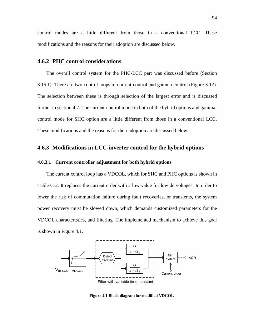
94
control modes are a little different from those in a conventional LCC. These
modifications and the reasons for their adoption are discussed below.
4.6.2 PHC control considerations
The overall control system for the PHC-LCC part was discussed before (Section
3.15.1). There are two control loops of current-control and gamma-control (Figure 3.12).
The selection between these is through selection of the largest error and is discussed
further in section 4.7. The current-control mode in both of the hybrid options and gamma-
control mode for SHC option are a little different from those in a conventional LCC.
These modifications and the reasons for their adoption are discussed below.
4.6.3 Modifications in LCC-inverter control for the hybrid options
4.6.3.1 Current controller adjustment for both hybrid options
The current control loop has a VDCOL, which for SHC and PHC options is shown in
Table C-2. It replaces the current order with a low value for low dc voltages. In order to
lower the risk of commutation failure during fault recoveries, or transients, the system
power recovery must be slowed down, which demands customized parameters for the
VDCOL characteristics, and filtering. The implemented mechanism to achieve this goal
is shown in Figure 4.1.
AORMin
Select
Current orderVDCOLVdc,LCC
Filter with variable time constant
Detect
direction
G
1 + sT1
G
1 + sT2
Figure 4.1 Block diagram for modified VDCOL
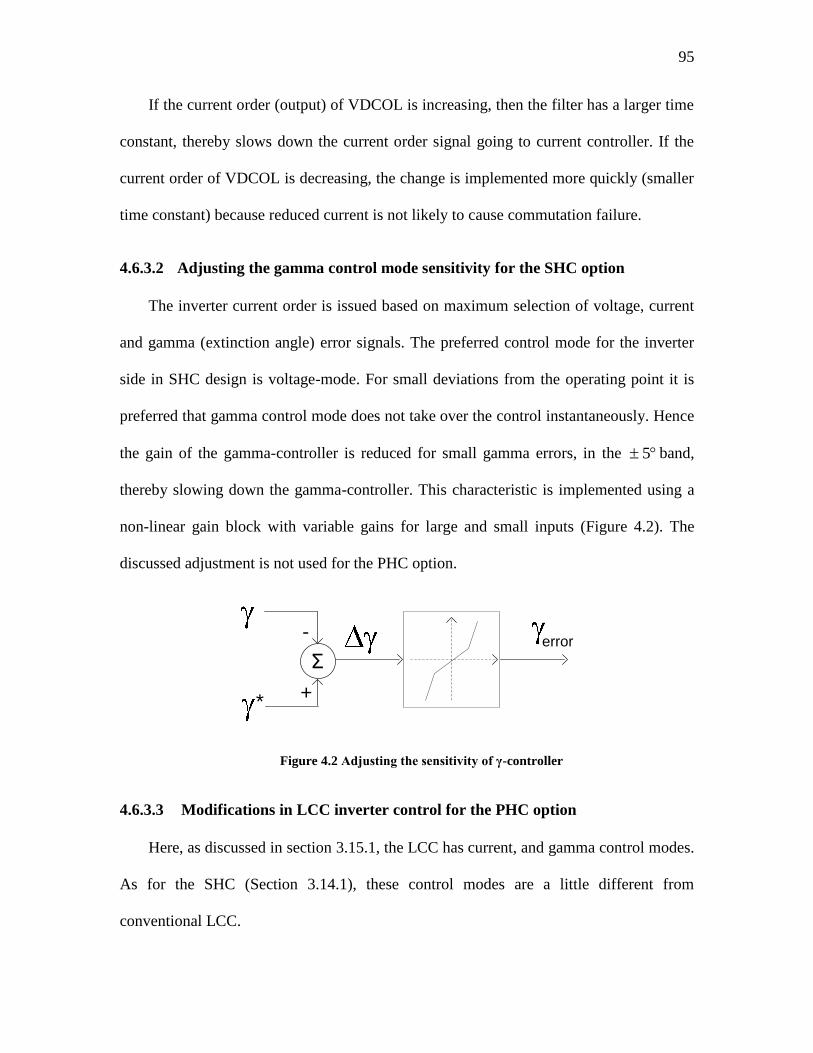
95
If the current order (output) of VDCOL is increasing, then the filter has a larger time
constant, thereby slows down the current order signal going to current controller. If the
current order of VDCOL is decreasing, the change is implemented more quickly (smaller
time constant) because reduced current is not likely to cause commutation failure.
4.6.3.2 Adjusting the gamma control mode sensitivity for the SHC option
The inverter current order is issued based on maximum selection of voltage, current
and gamma (extinction angle) error signals. The preferred control mode for the inverter
side in SHC design is voltage-mode. For small deviations from the operating point it is
preferred that gamma control mode does not take over the control instantaneously. Hence
the gain of the gamma-controller is reduced for small gamma errors, in the 5 band,
thereby slowing down the gamma-controller. This characteristic is implemented using a
non-linear gain block with variable gains for large and small inputs (Figure 4.2). The
discussed adjustment is not used for the PHC option.
+-
Σ
+*
error
Figure 4.2 Adjusting the sensitivity of γ-controller
4.6.3.3 Modifications in LCC inverter control for the PHC option
Here, as discussed in section 3.15.1, the LCC has current, and gamma control modes.
As for the SHC (Section 3.14.1), these control modes are a little different from
conventional LCC.
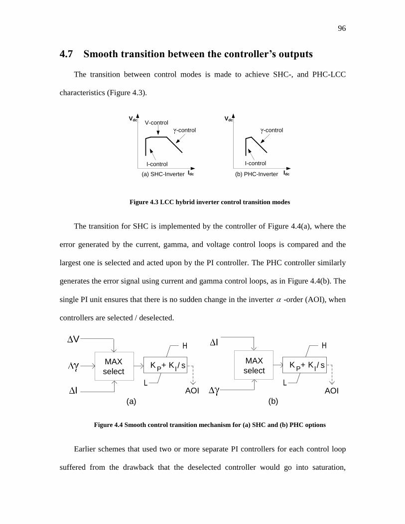
96
4.7 Smooth transition between the controller’s outputs
The transition between control modes is made to achieve SHC-, and PHC-LCC
characteristics (Figure 4.3).
Idc
Vdc
(a) SHC-Inverter
-control
V-control
I-control
Idc
Vdc
(b) PHC-Inverter
-control
I-control
Figure 4.3 LCC hybrid inverter control transition modes
The transition for SHC is implemented by the controller of Figure 4.4(a), where the
error generated by the current, gamma, and voltage control loops is compared and the
largest one is selected and acted upon by the PI controller. The PHC controller similarly
generates the error signal using current and gamma control loops, as in Figure 4.4(b). The
single PI unit ensures that there is no sudden change in the inverter -order (AOI), when
controllers are selected / deselected.
H
L
KP+ K
I / sMAX
select
AOI
(a)
V
I
MAX
select
H
L
KP
+ KI/ s
(b)
I
AOI
Figure 4.4 Smooth control transition mechanism for (a) SHC and (b) PHC options
Earlier schemes that used two or more separate PI controllers for each control loop
suffered from the drawback that the deselected controller would go into saturation,
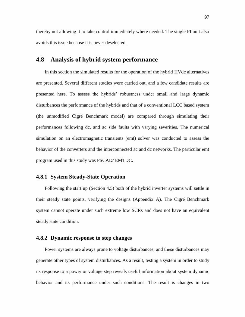
97
thereby not allowing it to take control immediately where needed. The single PI unit also
avoids this issue because it is never deselected.
4.8 Analysis of hybrid system performance
In this section the simulated results for the operation of the hybrid HVdc alternatives
are presented. Several different studies were carried out, and a few candidate results are
presented here. To assess the hybrids‟ robustness under small and large dynamic
disturbances the performance of the hybrids and that of a conventional LCC based system
(the unmodified Cigré Benchmark model) are compared through simulating their
performances following dc, and ac side faults with varying severities. The numerical
simulation on an electromagnetic transients (emt) solver was conducted to assess the
behavior of the converters and the interconnected ac and dc networks. The particular emt
program used in this study was PSCAD/ EMTDC.
4.8.1 System Steady-State Operation
Following the start up (Section 4.5) both of the hybrid inverter systems will settle in
their steady state points, verifying the designs (Appendix A). The Cigré Benchmark
system cannot operate under such extreme low SCRs and does not have an equivalent
steady state condition.
4.8.2 Dynamic response to step changes
Power systems are always prone to voltage disturbances, and these disturbances may
generate other types of system disturbances. As a result, testing a system in order to study
its response to a power or voltage step reveals useful information about system dynamic
behavior and its performance under such conditions. The result is changes in two
98
parameters of inverter terminal real power and ac voltage are of special interest. To
investigate both hybrid system responses to small set point changes a sequence of equal
magnitude step-down/step-up in power order was applied. The effect of step changes in
dc current reference and ac system relative strength (SCR) are also studied. Small
dynamic changes in VSC dc voltage reference will not be looked at, because based on the
implemented control method (Section 3.11) this dc voltage is not variable and has a fixed
reference point.
4.8.2.1 Dynamic response to step change in power order
To investigate both hybrid system responses to small power set point changes, a 10%
step-down followed by a subsequent 10% step-up in power order was applied to their
ordered signals. This step change is applied directly to the power order in SHC option;
For the PHC case this step change is applied proportionally to both the LCC inverter and
the VSC set points.
Figure 4.5 shows the SHC, PHC and LCC-only options‟ responses to the
mentioned set point changes. The power order step-down is applied at 0.1 second,
followed by the step-up at 1.1 second. The real power terminal, inverter and rectifier
terminal rms ac voltage for all of the three options is plotted in Figure 4.5(a)-(c),
respectively.
In the SHC option, the power order change is communicated via the change of
current order to the rectifier. Here the LCC-inverter and VSC both carry the same
current; the VSC maintains rated voltage on its ac busbar as well as rated voltage across
its dc terminals. This results in sharing the power change by the LCC-inverter and VSC
converters, in proportion to their relative ratings (Table C-3). Based on Figure 4.5(a), the
99
real terminal power reduction and its subsequent restoration to full magnitude for the
SHC option is achieved rapidly with no significant oscillation.
For the PHC option, the power order change is communicated through splitting
the total current order of the LCC-inverter and VSC parts into individual current orders,
in proportion to their designed ratings. The restoration to full power for the PHC is
poorer, showing oscillation and lasting for approximately 400 ms ( Figure 4.5(a)).
The LCC-only option also has a fast dynamic response, but demonstrates more
overshoot, accompanied by fast oscillations, compared to the hybrid options. However, it
must be noted that the LCC option is unable to operate into the inverter ac network with
low SCR that hybrid inverters are connected to, and it has been assumed that the SCR has
been increased to 2.5, by adding synchronous compensators, or other reactive
compensations devices. For this option, the power order change is communicated, in the
conventional manner, by dividing the power order by the inverter side voltage and
passing the result as the rectifier current order to the rectifier.
As the VSC in SHC is capable of reactive power generation and is tasked to
maintain the inverter ac terminal voltage ( InvacV , ) at a constant level, the voltage returns
to its pre-fault magnitude very rapidly, as shown in Figure 4.5(b), after applying the
power order change, which shows almost no sign of overvoltage. The PHC also regulates
this voltage, but the dynamic response is poorer. With the LCC-only option, the ac
voltage is poorly regulated and rises to about 10% overvoltage as the load is reduced; this
is not far from expectations, as no controller is aimed to regulate this voltage. As can be
seen from graphs of Figure 4.5 both of the hybrid options can track the power order
changes while
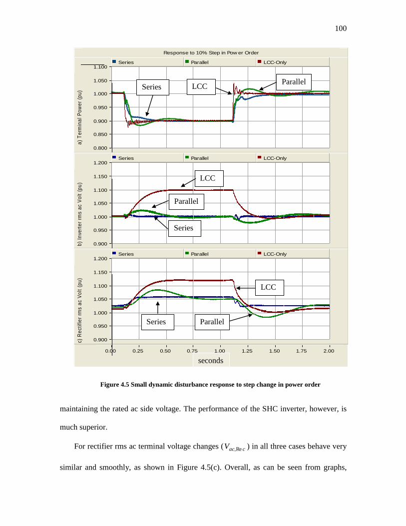
100
Response to 10% Step in Pow er Order
0.00 0.25 0.50 0.75 1.00 1.25 1.50 1.75 2.00 ...
...
...
0.800
0.850
0.900
0.950
1.000
1.050
1.100
a)
Te
rmin
al
Po
we
r (p
u)
Series Parallel LCC-Only
0.900
0.950
1.000
1.050
1.100
1.150
1.200
b)
Inve
rte
r rm
s a
c V
olt
(p
u)
Series Parallel LCC-Only
0.900
0.950
1.000
1.050
1.100
1.150
1.200
c) R
ect
ifie
r rm
s a
c V
olt
(p
u)
Series Parallel LCC-Only
Figure 4.5 Small dynamic disturbance response to step change in power order
maintaining the rated ac side voltage. The performance of the SHC inverter, however, is
much superior.
For rectifier rms ac terminal voltage changes ( cacV Re, ) in all three cases behave very
similar and smoothly, as shown in Figure 4.5(c). Overall, as can be seen from graphs,
Series LCC Parallel
Series
LCC
Parallel
Series
LCC
Parallel
seconds
101
both hybrid options show quick, and well damped responses to the small power set-point
changes.
4.8.2.2 Dynamic response to rectifier dc current order
To investigate the systems‟ performance when the rectifier dc current is changed, a
5% step down followed by a 5% step-up in dc current is applied to rectifier dc current
signal at 0.1, and 1.1 seconds, respectively, after system has settled down. In Figure
4.6(a) and (b) the ac inverter terminal real power and rms ac voltage is plotted,
respectively.
As evidenced by the graphs, the terminal real power behaves very well for all of the
three cases, though the PHC has a little oscillatory behavior, as shown in Figure 4.6(a).
For the hybrid options the inverter rms ac voltage has almost no visible disturbance
because of fast VSC voltage correction. In the LCC-only case corrective action is missing
because no controller has been assigned for such correction.
As can be seen from the figures, both of the hybrid options can track the power
order changes while maintaining the rated ac side voltage. The performance of the SHC
inverter, however, is much superior.
4.8.3 System response to inverter side short circuit ratio changes
To simulate the effect of sudden changes in ac-side configuration such as line
insertion / removal or adding/subtracting generating capacity, a step change in the short
circuit ratio of the ac system was applied. The ac-side short circuit ratio at the inverter
side is increased by 25%, from SCR = 1 to SCR = 1.25 at t = 0.1 second; then later, at t =
1.1 second, the short circuit ratio is lowered back to SCR = 1. The dynamic effects of
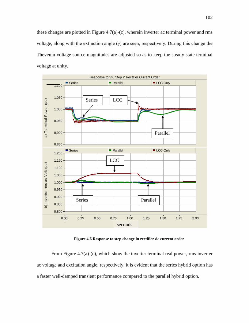
102
these changes are plotted in Figure 4.7(a)-(c), wherein inverter ac terminal power and rms
voltage, along with the extinction angle (γ) are seen, respectively. During this change the
Thevenin voltage source magnitudes are adjusted so as to keep the steady state terminal
voltage at unity.
Response to 5% Step in Rectif ier Current Order
0.00 0.25 0.50 0.75 1.00 1.25 1.50 1.75 2.00 ...
...
...
0.850
0.900
0.950
1.000
1.050
1.100
a)
Te
rmin
al
Po
we
r (p
u)
Series Parallel LCC-Only
0.800
0.850
0.900
0.950
1.000
1.050
1.100
1.150
1.200
b)
Inve
rte
r rm
s a
c V
olt
(p
u)
Series Parallel LCC-Only
Figure 4.6 Response to step change in rectifier dc current order
From Figure 4.7(a)-(c), which show the inverter terminal real power, rms inverter
ac voltage and excitation angle, respectively, it is evident that the series hybrid option has
a faster well-damped transient performance compared to the parallel hybrid option.
Series
LCC
Parallel
Series LCC
Parallel
seconds
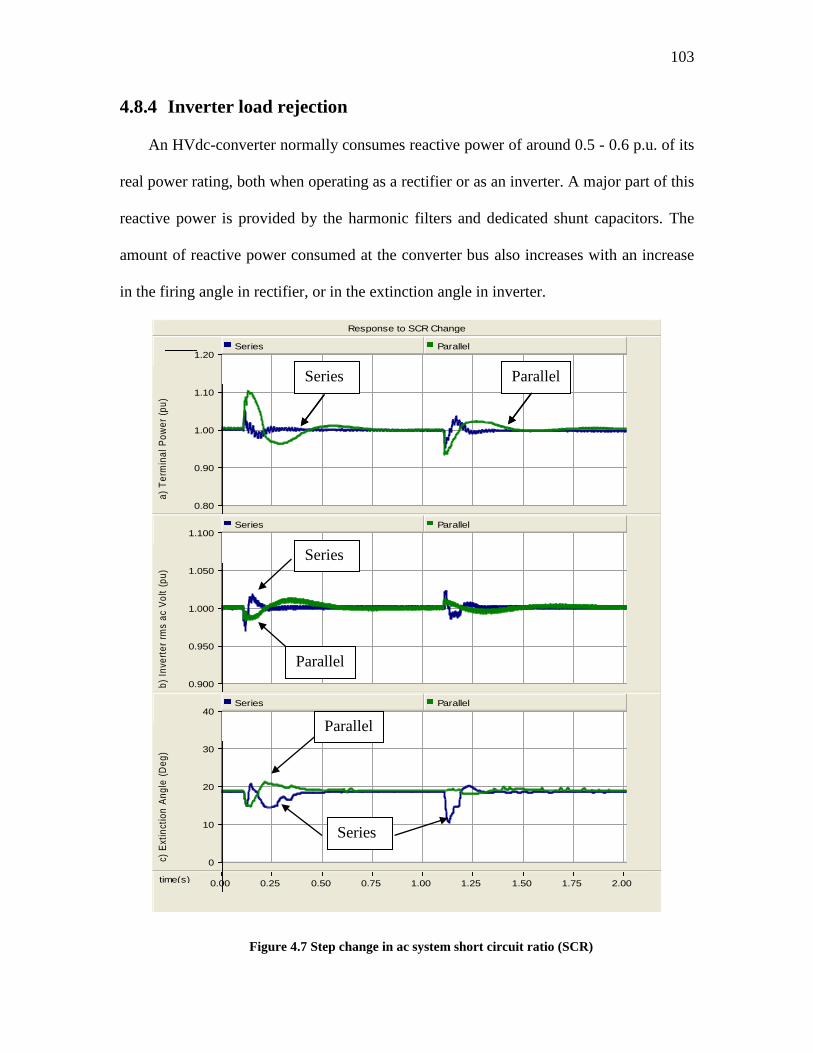
103
4.8.4 Inverter load rejection
An HVdc-converter normally consumes reactive power of around 0.5 - 0.6 p.u. of its
real power rating, both when operating as a rectifier or as an inverter. A major part of this
reactive power is provided by the harmonic filters and dedicated shunt capacitors. The
amount of reactive power consumed at the converter bus also increases with an increase
in the firing angle in rectifier, or in the extinction angle in inverter.
Response to SCR Change
time(s) 0.00 0.25 0.50 0.75 1.00 1.25 1.50 1.75 2.00 ...
...
...
0.80
0.90
1.00
1.10
1.20
a)
Te
rmin
al
Po
we
r (p
u)
Series Parallel
0.900
0.950
1.000
1.050
1.100
b)
Inve
rte
r rm
s a
c V
olt
(p
u)
Series Parallel
0
10
20
30
40
c) E
xtin
ctio
n A
ng
le (
De
g)
Series Parallel
Figure 4.7 Step change in ac system short circuit ratio (SCR)
Series Parallel
Series
Parallel
Series Parallel
Series
Parallel
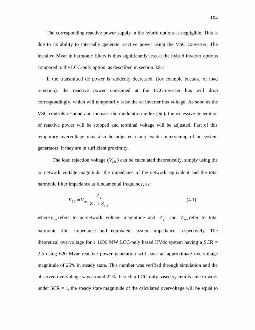
104
The corresponding reactive power supply in the hybrid options is negligible. This is
due to its ability to internally generate reactive power using the VSC converter. The
installed Mvar in harmonic filters is thus significantly less at the hybrid inverter options
compared to the LCC-only option, as described in section 3.9.1.
If the transmitted dc power is suddenly decreased, (for example because of load
rejection), the reactive power consumed at the LCC-inverter bus will drop
correspondingly, which will temporarily raise the ac inverter bus voltage. As soon as the
VSC controls respond and increase the modulation index ( m ), the excessive generation
of reactive power will be stopped and terminal voltage will be adjusted. Part of this
temporary overvoltage may also be adjusted using exciter intervening of ac system
generators, if they are in sufficient proximity.
The load rejection voltage ( LRV ) can be calculated theoretically, simply using the
ac network voltage magnitude, the impedance of the network equivalent and the total
harmonic filter impedance at fundamental frequency, as:
sysf
f
sysLRZZ
ZVV
(4.1)
where sysV refers to ac-network voltage magnitude and fZ and sysZ refer to total
harmonic filter impedance and equivalent system impedance, respectively. The
theoretical overvoltage for a 1000 MW LCC-only based HVdc system having a SCR =
2.5 using 620 Mvar reactive power generation will have an approximate overvoltage
magnitude of 25% in steady state. This number was verified through simulation and the
observed overvoltage was around 22%. If such a LCC-only based system is able to work
under SCR = 1, the steady state magnitude of the calculated overvoltage will be equal to
105
around 62%. If the reactive power generation can be lowered to around 100 Mvar, the
overvoltage would be around 10%.
On the other hand, with the assumption of a hybrid inverter system (series or parallel
inverter based) with 1000 MW dc power rating with total reactive power generation from
ac filters of around 100 Mvar at the inverter side (for SCR =1), the steady state
magnitude of the calculated overvoltage will be 10%, given no intervening from the VSC
converter. In practice, the VSC would interfere and change the scenario.
In Figure 4.8 the inverter rms ac voltage response to a complete (100%) inverter load
rejection is given. Comparing the graphs with the calculated numbers shows that results
agree very well.
Simulation of the system (Figure 4.8) resulted in transient overvoltages of around 7%
for the SHC and 2.5% for the PHC option, and zero steady-state overvoltage. The
presence of the VSC converter lowers the load rejection overvoltage not only because of
the need for smaller amount of installed reactive power converters (harmonic filters) at
the inverter terminal bus, but also because of its ability to regulate reactive power through
the VSC. It is concluded that regarding overvoltage performance, the hybrid converters
have superior performance, even when they are connected to very weak ac systems.
4.8.5 Large signal response and fault recovery performance
The response of the SHC, PHC and LCC-only options to large dynamic disturbances
in the form of ac and dc faults was investigated. All categories of ac faults (3, 2, and
single phase faults to ground) with a wide range of fault impedances were applied to
inverter and to rectifier terminals for a period of 0.1 second (6 cycles). The results are
discussed in the following sections.
106
AC System Inverter Load Rejection
time(s) 0.00 0.10 0.20 0.30 0.40 0.50 0.60 0.70 0.80 0.90 1.00 ...
...
...
0.80
0.90
1.00
1.10
1.20
1.30
In
ve
rte
r rm
s a
c V
olt
(p
u)
Series Parallel LCC-Only
Figure 4.8 Overvoltage following an inverter load rejection
4.8.5.1 Three-phase ac inverter-side faults
Applying a three phase (close-in) fault at the ac inverter terminal is one of the most
critical tests to very weak systems. Such a fault effectively reduces the inverter terminal
voltage to zero. To simulate the effect of this fault a 0.005 p.u. inductance was shunt
connected to the ac inverter terminal for 0.1 seconds. The inverter terminal power,
inverter side rms ac voltage, and extinction angle ( ) for the both hybrid options and the
LCC-only option are shown in Figure 4.9(a)-(c), respectively.
As seen from Figure 4.9(a), the power recovery of the SHC option to 90% of the
nominal power takes around 250 ms, which is nearly identical to the LCC-only option.
Note that the LCC-only option has by necessity, a larger ac system SCR of 2.5 (as
mentioned earlier operation at SCR = 1 is not possible for the LCC option), whereas the
SHC has a much weaker ac system (SCR = 1). This shows that in comparison with LCC-
only technology, the SHC option can achieve comparable performance even with short
circuit ratios which are significantly smaller. For the PHC option, however, the recovery
Series
LCC Parallel
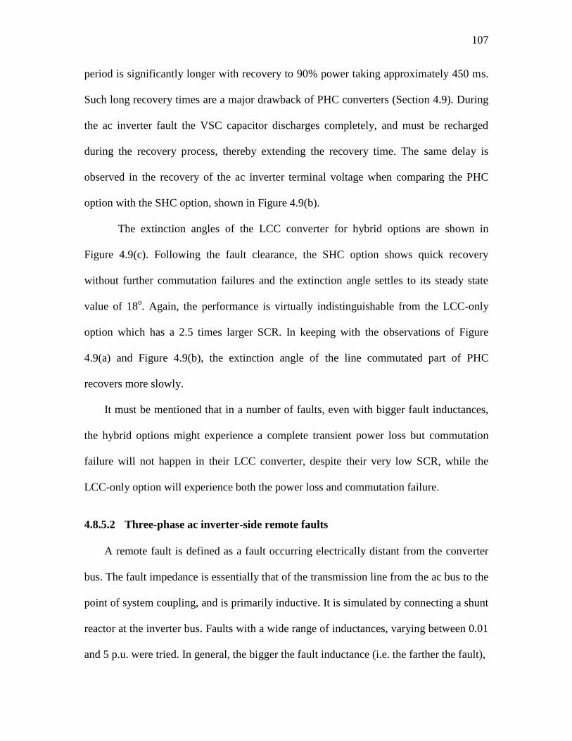
107
period is significantly longer with recovery to 90% power taking approximately 450 ms.
Such long recovery times are a major drawback of PHC converters (Section 4.9). During
the ac inverter fault the VSC capacitor discharges completely, and must be recharged
during the recovery process, thereby extending the recovery time. The same delay is
observed in the recovery of the ac inverter terminal voltage when comparing the PHC
option with the SHC option, shown in Figure 4.9(b).
The extinction angles of the LCC converter for hybrid options are shown in
Figure 4.9(c). Following the fault clearance, the SHC option shows quick recovery
without further commutation failures and the extinction angle settles to its steady state
value of 18o. Again, the performance is virtually indistinguishable from the LCC-only
option which has a 2.5 times larger SCR. In keeping with the observations of Figure
4.9(a) and Figure 4.9(b), the extinction angle of the line commutated part of PHC
recovers more slowly.
It must be mentioned that in a number of faults, even with bigger fault inductances,
the hybrid options might experience a complete transient power loss but commutation
failure will not happen in their LCC converter, despite their very low SCR, while the
LCC-only option will experience both the power loss and commutation failure.
4.8.5.2 Three-phase ac inverter-side remote faults
A remote fault is defined as a fault occurring electrically distant from the converter
bus. The fault impedance is essentially that of the transmission line from the ac bus to the
point of system coupling, and is primarily inductive. It is simulated by connecting a shunt
reactor at the inverter bus. Faults with a wide range of inductances, varying between 0.01
and 5 p.u. were tried. In general, the bigger the fault inductance (i.e. the farther the fault),
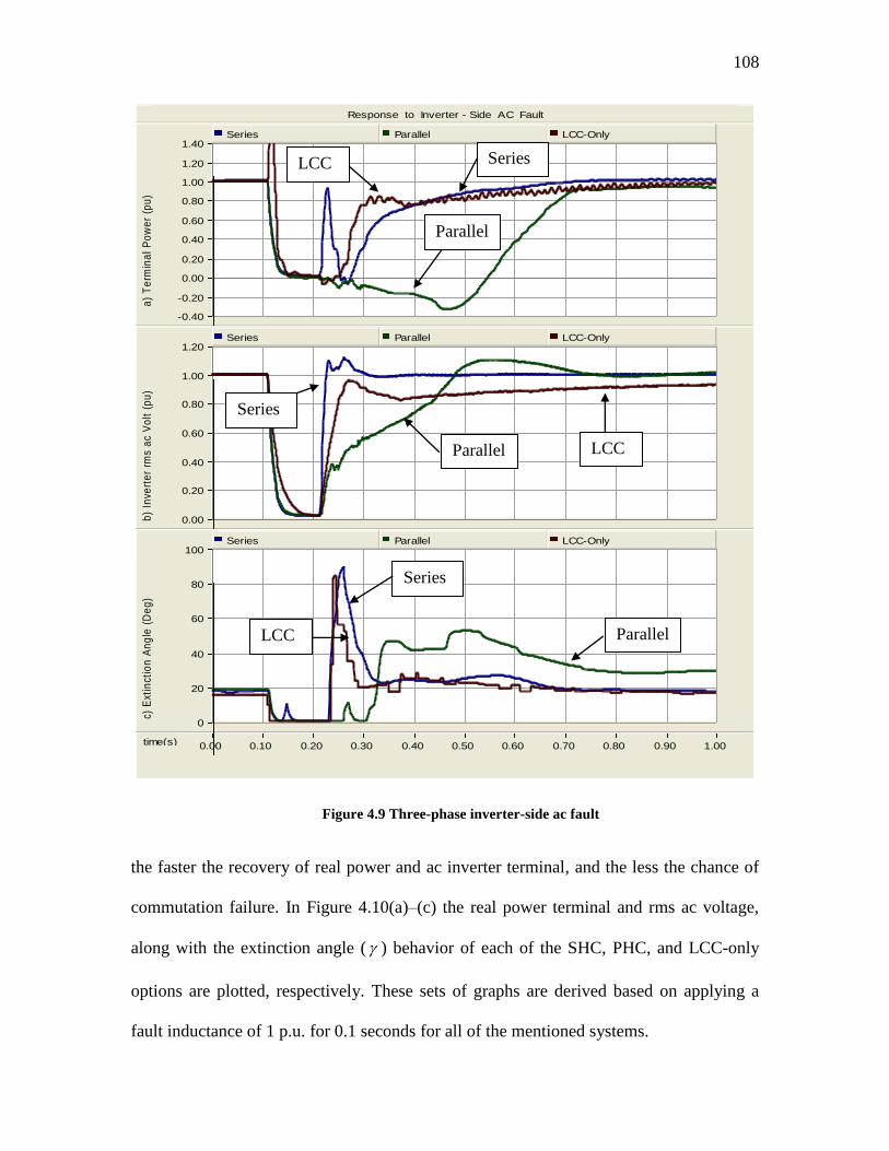
108
Response to Inverter - Side AC Fault
time(s) 0.00 0.10 0.20 0.30 0.40 0.50 0.60 0.70 0.80 0.90 1.00 ...
...
...
-0.40
-0.20
0.00
0.20
0.40
0.60
0.80
1.00
1.20
1.40 a
) T
erm
ina
l P
ow
er
(pu
)Series Parallel LCC-Only
0.00
0.20
0.40
0.60
0.80
1.00
1.20
b)
Inve
rte
r rm
s a
c V
olt
(p
u)
Series Parallel LCC-Only
0
20
40
60
80
100
c) E
xtin
ctio
n A
ng
le (
De
g)
Series Parallel LCC-Only
Figure 4.9 Three-phase inverter-side ac fault
the faster the recovery of real power and ac inverter terminal, and the less the chance of
commutation failure. In Figure 4.10(a)–(c) the real power terminal and rms ac voltage,
along with the extinction angle ( ) behavior of each of the SHC, PHC, and LCC-only
options are plotted, respectively. These sets of graphs are derived based on applying a
fault inductance of 1 p.u. for 0.1 seconds for all of the mentioned systems.
Series LCC
Parallel
Series
LCC Parallel
Series
LCC Parallel
109
As seen in Figure 4.10(a), the terminal real powers are much disturbed for all of the
cases. The series option has, on the other hand, excellent and rapid power recovery in
around 150 ms after fault clearance. Again, the parallel option has a long power recovery
time of around 600 ms, as discussed in 4.8.5.1. At around 370 ms, another commutation
failure occurs in the LCC-only converter, temporarily bringing terminal power to zero.
The ac inverter terminal voltages are moderately disturbed, with the lowest voltage
drop for the SHC and the most affected one being the PHC. The LCC-only option lies in
between these two extremes Figure 4.10(b). The series hybrid converter undergoes an ac
rapid voltage recovery in comparison with other options.
From Figure 4.10(c), the hybrid inverters and LCC-only option experience
commutation failures. However, the SHC option recovers most rapidly. The LCC-only
option starts to recover, but another commutation failure happens in the LCC converter.
Changing the fault duration time between around 50 to 200 ms did not cause any
distinctive change in general systems‟ transient behavior but it has an impact on the
recovery performance. Hence in conclusion the SHC option has a superior behavior in
power recovery and re-adjusting its ac terminal voltage and its extinction angle.
4.8.5.3 Single-phase ac inverter-side faults
The same conclusion regarding fault performance can be drawn when a close-in
single-phase line-to-ground fault is applied at the ac inverter terminal. From the
simulated recovery plots of Figure 4.11(a)-(c) which is based on a 0.005 p.u. fault
inductance, system recovery behavior is very similar to the three phase (close-in)
inverter-side ac faults. Again, the SHC has a very similar power recovery trend with the
LCC-only case, but the PHC undergoes an erratic and unacceptable terminal power
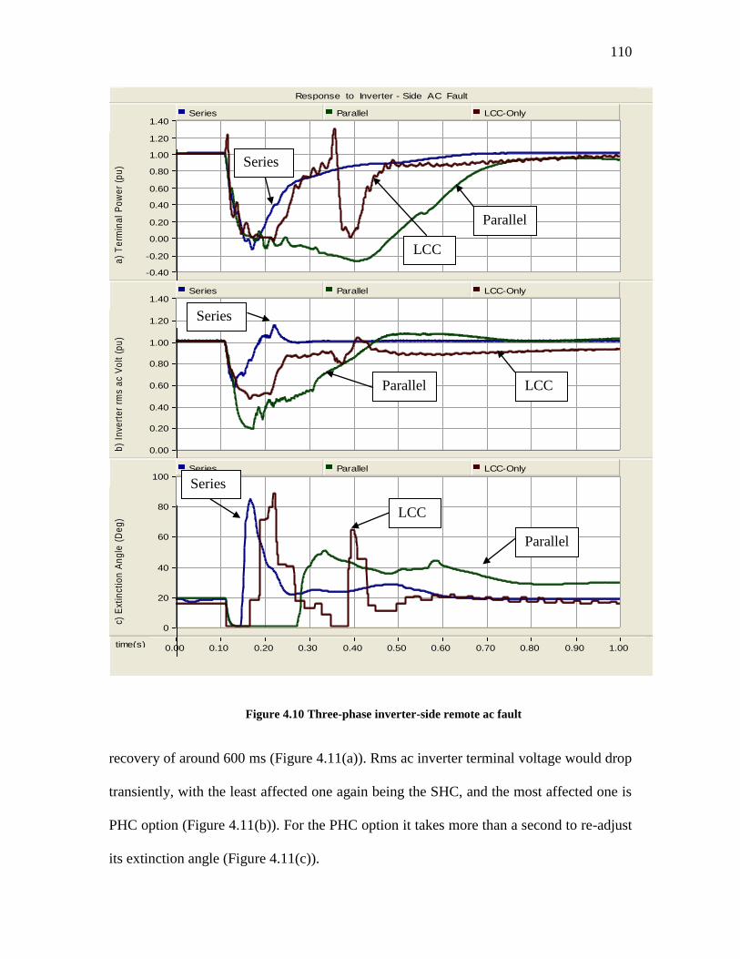
110
Response to Inverter - Side AC Fault
time(s) 0.00 0.10 0.20 0.30 0.40 0.50 0.60 0.70 0.80 0.90 1.00 ...
...
...
-0.40
-0.20
0.00
0.20
0.40
0.60
0.80
1.00
1.20
1.40 a
) T
erm
ina
l P
ow
er
(pu
)Series Parallel LCC-Only
0.00
0.20
0.40
0.60
0.80
1.00
1.20
1.40
b)
Inve
rte
r rm
s a
c V
olt
(p
u)
Series Parallel LCC-Only
0
20
40
60
80
100
c) E
xtin
ctio
n A
ng
le (
De
g)
Series Parallel LCC-Only
Figure 4.10 Three-phase inverter-side remote ac fault
recovery of around 600 ms (Figure 4.11(a)). Rms ac inverter terminal voltage would drop
transiently, with the least affected one again being the SHC, and the most affected one is
PHC option (Figure 4.11(b)). For the PHC option it takes more than a second to re-adjust
its extinction angle (Figure 4.11(c)).
Series
LCC
Parallel
Series
LCC Parallel
Series
LCC
Parallel
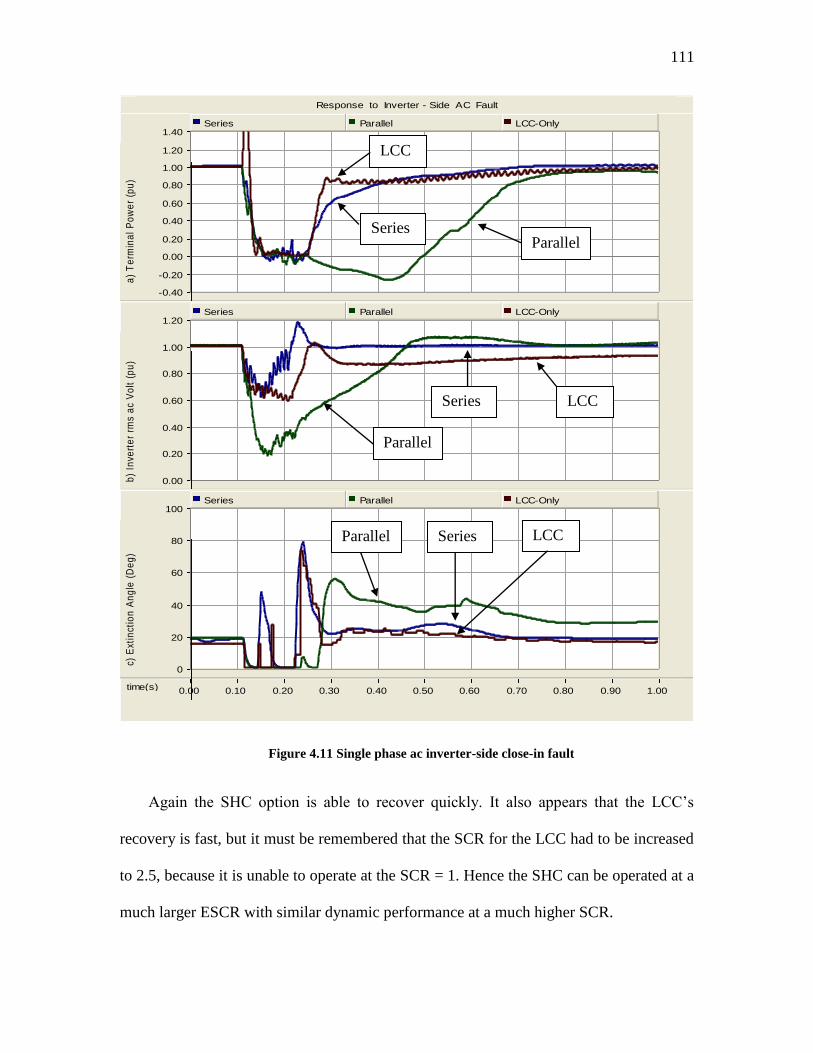
111
Response to Inverter - Side AC Fault
time(s) 0.00 0.10 0.20 0.30 0.40 0.50 0.60 0.70 0.80 0.90 1.00 ...
...
...
-0.40
-0.20
0.00
0.20
0.40
0.60
0.80
1.00
1.20
1.40 a
) T
erm
ina
l P
ow
er
(pu
)Series Parallel LCC-Only
0.00
0.20
0.40
0.60
0.80
1.00
1.20
b)
Inve
rte
r rm
s a
c V
olt
(p
u)
Series Parallel LCC-Only
0
20
40
60
80
100
c) E
xtin
ctio
n A
ng
le (
De
g)
Series Parallel LCC-Only
Figure 4.11 Single phase ac inverter-side close-in fault
Again the SHC option is able to recover quickly. It also appears that the LCC‟s
recovery is fast, but it must be remembered that the SCR for the LCC had to be increased
to 2.5, because it is unable to operate at the SCR = 1. Hence the SHC can be operated at a
much larger ESCR with similar dynamic performance at a much higher SCR.
Series
LCC
Parallel
Series LCC
Parallel
Series LCC Parallel
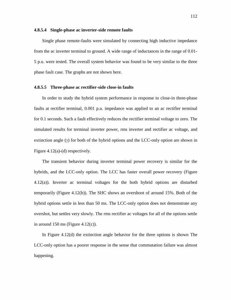
112
4.8.5.4 Single-phase ac inverter-side remote faults
Single phase remote-faults were simulated by connecting high inductive impedance
from the ac inverter terminal to ground. A wide range of inductances in the range of 0.01-
5 p.u. were tested. The overall system behavior was found to be very similar to the three
phase fault case. The graphs are not shown here.
4.8.5.5 Three-phase ac rectifier-side close-in faults
In order to study the hybrid system performance in response to close-in three-phase
faults at rectifier terminal, 0.001 p.u. impedance was applied to an ac rectifier terminal
for 0.1 seconds. Such a fault effectively reduces the rectifier terminal voltage to zero. The
simulated results for terminal inverter power, rms inverter and rectifier ac voltage, and
extinction angle () for both of the hybrid options and the LCC-only option are shown in
Figure 4.12(a)-(d) respectively.
The transient behavior during inverter terminal power recovery is similar for the
hybrids, and the LCC-only option. The LCC has faster overall power recovery (Figure
4.12(a)). Inverter ac terminal voltages for the both hybrid options are disturbed
temporarily (Figure 4.12(b)). The SHC shows an overshoot of around 15%. Both of the
hybrid options settle in less than 50 ms. The LCC-only option does not demonstrate any
overshot, but settles very slowly. The rms rectifier ac voltages for all of the options settle
in around 150 ms (Figure 4.12(c)).
In Figure 4.12(d) the extinction angle behavior for the three options is shown The
LCC-only option has a poorer response in the sense that commutation failure was almost
happening.
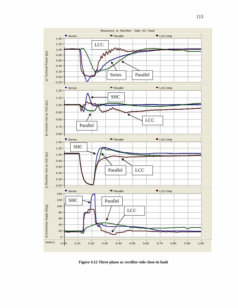
113
Response to Rectif ier - Side AC Fault
time(s) 0.00 0.10 0.20 0.30 0.40 0.50 0.60 0.70 0.80 0.90 1.00 ...
...
...
-0.20
0.00
0.20
0.40
0.60
0.80
1.00
1.20
1.40
a)
Te
rmin
al
Po
we
r (p
u)
Series Parallel LCC-Only
0.60
0.70
0.80
0.90
1.00
1.10
1.20
b)
Inve
rte
r rm
s a
c V
olt
(p
u)
Series Parallel LCC-Only
0.00
0.20
0.40
0.60
0.80
1.00
1.20
1.40
c) R
ect
ifie
r rm
s a
c V
olt
(p
u)
Series Parallel LCC-Only
0
20
40
60
80
100
120
140
d)
Ext
inct
ion
An
gle
(D
eg
)
Series Parallel LCC-Only
Figure 4.12 Three phase ac rectifier-side close-in fault
SHC
LCC Paralle
l
LCC
Parallel Series
SHC
LCC Parallel
SHC
LCC Parallel
SHC
LCC
Parallel
114
4.8.5.6 Three-phase ac rectifier-side remote faults
Remote faults in the rectifier ac bus were applied using different magnitudes. The
graphs of Figure 4.13(a)-(d) were simulated using a 1-p.u. inductance. Here, the inverter
terminal real power, rms inverter and rectifier ac terminal voltages, and extinction angle
behavior for both of the hybrid and LCC-only options are plotted, respectively.
The transient behavior during inverter terminal power recovery is similar for the
hybrids, and the LCC-only option. The LCC has faster overall power recovery (Figure
4.13 (a)). At around 300 ms, another commutation failure occurs in the LCC-only
converter, temporarily bringing terminal power to zero.
In response to the applied fault, the inverter ac terminal voltages of the series and
parallel options demonstrate overshoots of 15% and 10%, , respectively, but settle in less
than 100 ms. For the LCC-only option, however, an overshot of 10%, followed by a
settling time of longer than one second is observed (Figure 4.13 (b)).
The rectifier fault causes almost equal rectifier voltage drops in both of the hybrids
followed by 20% terminal transient overvoltage, which settles to its steady state in around
200 ms. The LCC-only option drops much more, to around 40%, but does not suffer from
a significant overvoltage. It takes more than a second for the rectifier terminal voltage to
settle to its nominal voltage (Figure 4.13(c)).
It is worth mentioning that neither of the hybrid options demonstrates a commutation
failure during or after fault clearance. The LCC-only option, on the other hand,
experiences a commutation failure after fault clearance (Figure 4.13 (d)). It can be
concluded that both of the hybrid options are more immune to commutation failure
during such ac rectifier side faults.
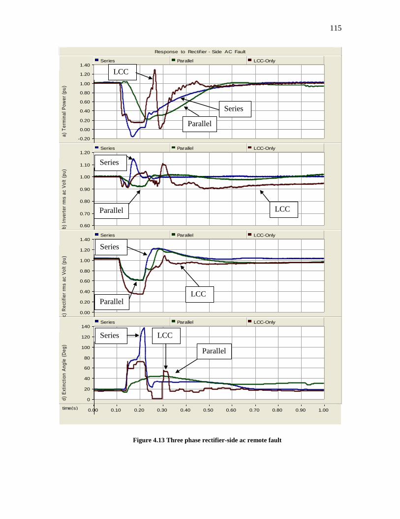
115
Response to Rectif ier - Side AC Fault
time(s) 0.00 0.10 0.20 0.30 0.40 0.50 0.60 0.70 0.80 0.90 1.00 ...
...
...
-0.20
0.00
0.20
0.40
0.60
0.80
1.00
1.20
1.40 a
) T
erm
ina
l P
ow
er
(pu
)Series Parallel LCC-Only
0.60
0.70
0.80
0.90
1.00
1.10
1.20
b)
Inve
rte
r rm
s a
c V
olt
(p
u)
Series Parallel LCC-Only
0.00
0.20
0.40
0.60
0.80
1.00
1.20
1.40
c) R
ect
ifie
r rm
s a
c V
olt
(p
u)
Series Parallel LCC-Only
0
20
40
60
80
100
120
140
d)
Ext
inct
ion
An
gle
(D
eg
)
Series Parallel LCC-Only
Figure 4.13 Three phase rectifier-side ac remote fault
Series
LCC Parallel
Series
LCC
Parallel
Series LCC
Parallel
Series
LCC Parallel
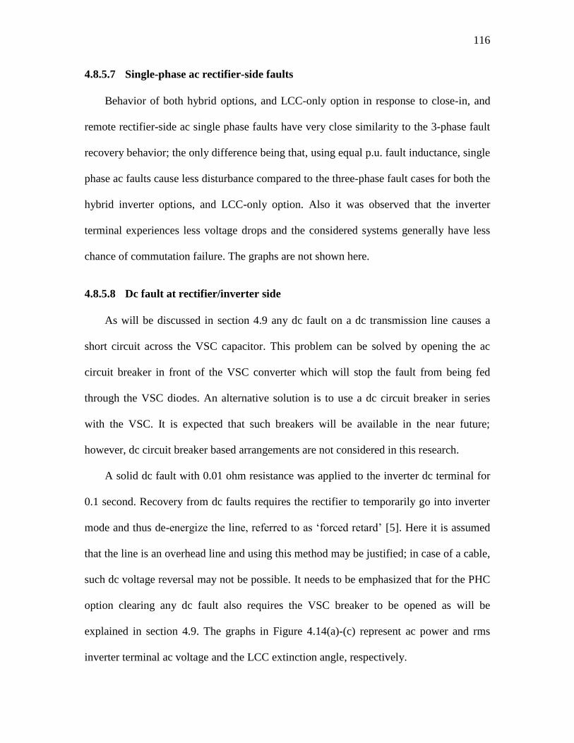
116
4.8.5.7 Single-phase ac rectifier-side faults
Behavior of both hybrid options, and LCC-only option in response to close-in, and
remote rectifier-side ac single phase faults have very close similarity to the 3-phase fault
recovery behavior; the only difference being that, using equal p.u. fault inductance, single
phase ac faults cause less disturbance compared to the three-phase fault cases for both the
hybrid inverter options, and LCC-only option. Also it was observed that the inverter
terminal experiences less voltage drops and the considered systems generally have less
chance of commutation failure. The graphs are not shown here.
4.8.5.8 Dc fault at rectifier/inverter side
As will be discussed in section 4.9 any dc fault on a dc transmission line causes a
short circuit across the VSC capacitor. This problem can be solved by opening the ac
circuit breaker in front of the VSC converter which will stop the fault from being fed
through the VSC diodes. An alternative solution is to use a dc circuit breaker in series
with the VSC. It is expected that such breakers will be available in the near future;
however, dc circuit breaker based arrangements are not considered in this research.
A solid dc fault with 0.01 ohm resistance was applied to the inverter dc terminal for
0.1 second. Recovery from dc faults requires the rectifier to temporarily go into inverter
mode and thus de-energize the line, referred to as „forced retard‟ [5]. Here it is assumed
that the line is an overhead line and using this method may be justified; in case of a cable,
such dc voltage reversal may not be possible. It needs to be emphasized that for the PHC
option clearing any dc fault also requires the VSC breaker to be opened as will be
explained in section 4.9. The graphs in Figure 4.14(a)-(c) represent ac power and rms
inverter terminal ac voltage and the LCC extinction angle, respectively.
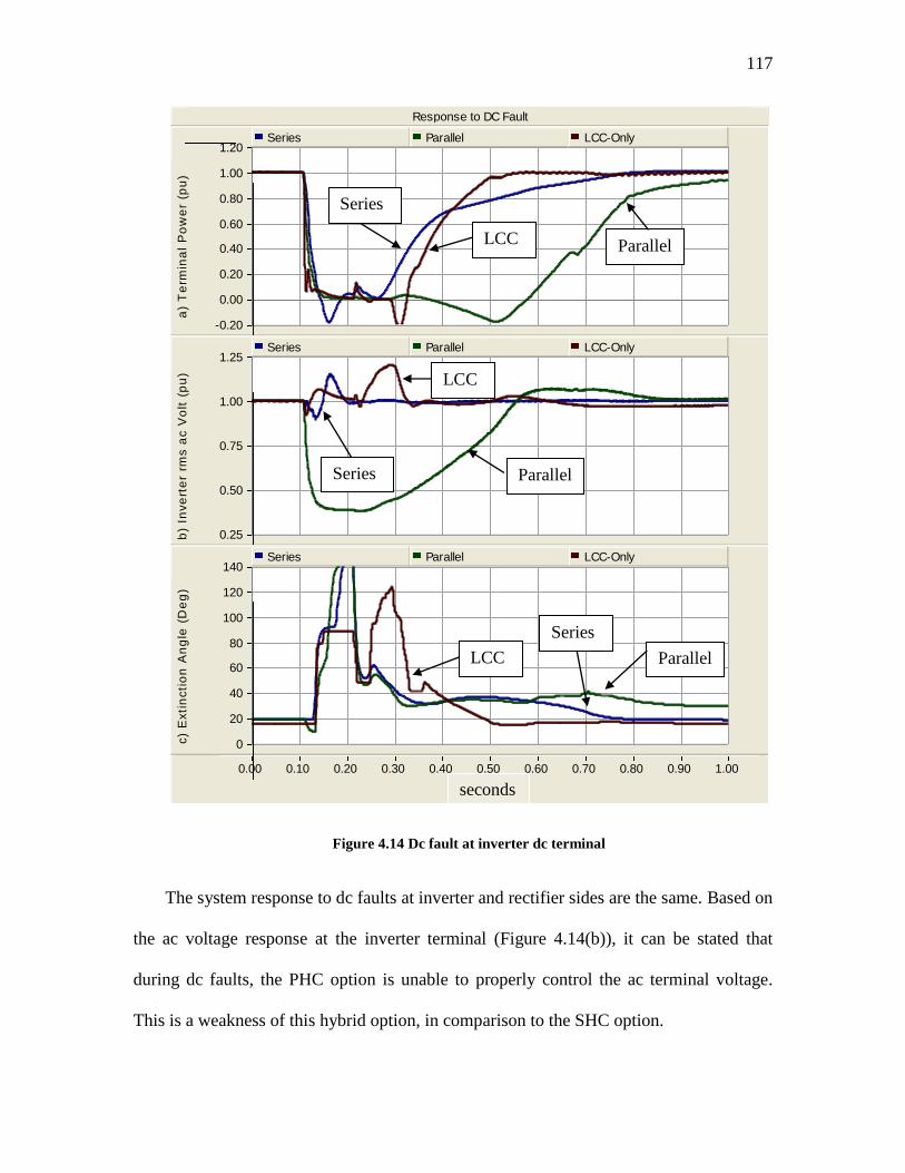
117
Response to DC Fault
0.00 0.10 0.20 0.30 0.40 0.50 0.60 0.70 0.80 0.90 1.00 ...
...
...
-0.20
0.00
0.20
0.40
0.60
0.80
1.00
1.20
a)
Te
rmin
al
Po
we
r (p
u)
Series Parallel LCC-Only
0.25
0.50
0.75
1.00
1.25
b)
Inve
rte
r rm
s a
c V
olt
(p
u)
Series Parallel LCC-Only
0
20
40
60
80
100
120
140
c)
Exti
ncti
on
An
gle
(D
eg
)
Series Parallel LCC-Only
Figure 4.14 Dc fault at inverter dc terminal
The system response to dc faults at inverter and rectifier sides are the same. Based on
the ac voltage response at the inverter terminal (Figure 4.14(b)), it can be stated that
during dc faults, the PHC option is unable to properly control the ac terminal voltage.
This is a weakness of this hybrid option, in comparison to the SHC option.
Series
LCC Parallel
Series
LCC
Parallel
Series
LCC Parallel
seconds
118
4.9 Intrinsic drawback of parallel hybrid converters (PHC)
Any ac fault applied at the inverter side which causes commutation failure will eventually
end up with a LCC converter bypass operation that effectively demonstrates a short
circuit across the VSC capacitor (Figure 4.15). This results in a short circuit current with
contributions from the discharging capacitor as well as the ac system through the VSC
diodes, assuming that the ac voltage will not drop to zero. The LCC converter is unable to
recover and resume normal operation as long as the VSC continues feeding the bypass
loop completed through two thyristors, such as thyristors 6 and 3 (Figure 4.15). This is
because the dc current supplied through VSC is much larger than the nominal dc current.
This situation is even worse in a system with low SCR. In such case the VSC (now
behaving like a diode bridge) absorbs large amounts of reactive power while feeding the
short circuit. This in turn causes a substantial drop in ac voltage which also makes it more
difficult for the LCC inverter to recover.
Vac,Inv
XL1
XL2
Vdc,VSC
Vdc,LCCVdi C
Idc L
Idc,LCCIdc,VSC
F
4 6 2
1 3 5
Figure 4.15 Circulating current in PHC option during an ac inverter-side fault
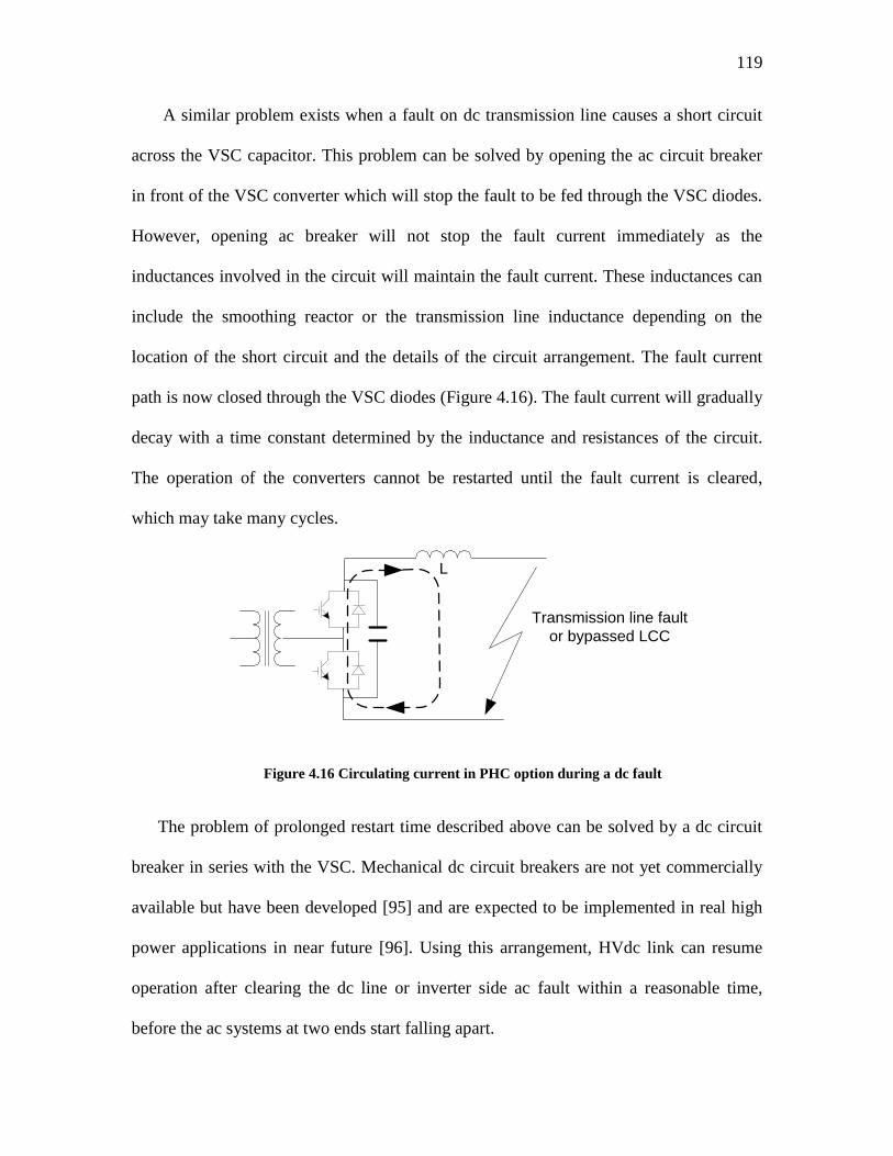
119
A similar problem exists when a fault on dc transmission line causes a short circuit
across the VSC capacitor. This problem can be solved by opening the ac circuit breaker
in front of the VSC converter which will stop the fault to be fed through the VSC diodes.
However, opening ac breaker will not stop the fault current immediately as the
inductances involved in the circuit will maintain the fault current. These inductances can
include the smoothing reactor or the transmission line inductance depending on the
location of the short circuit and the details of the circuit arrangement. The fault current
path is now closed through the VSC diodes (Figure 4.16). The fault current will gradually
decay with a time constant determined by the inductance and resistances of the circuit.
The operation of the converters cannot be restarted until the fault current is cleared,
which may take many cycles.
Transmission line fault
or bypassed LCC
L
Figure 4.16 Circulating current in PHC option during a dc fault
The problem of prolonged restart time described above can be solved by a dc circuit
breaker in series with the VSC. Mechanical dc circuit breakers are not yet commercially
available but have been developed [95] and are expected to be implemented in real high
power applications in near future [96]. Using this arrangement, HVdc link can resume
operation after clearing the dc line or inverter side ac fault within a reasonable time,
before the ac systems at two ends start falling apart.
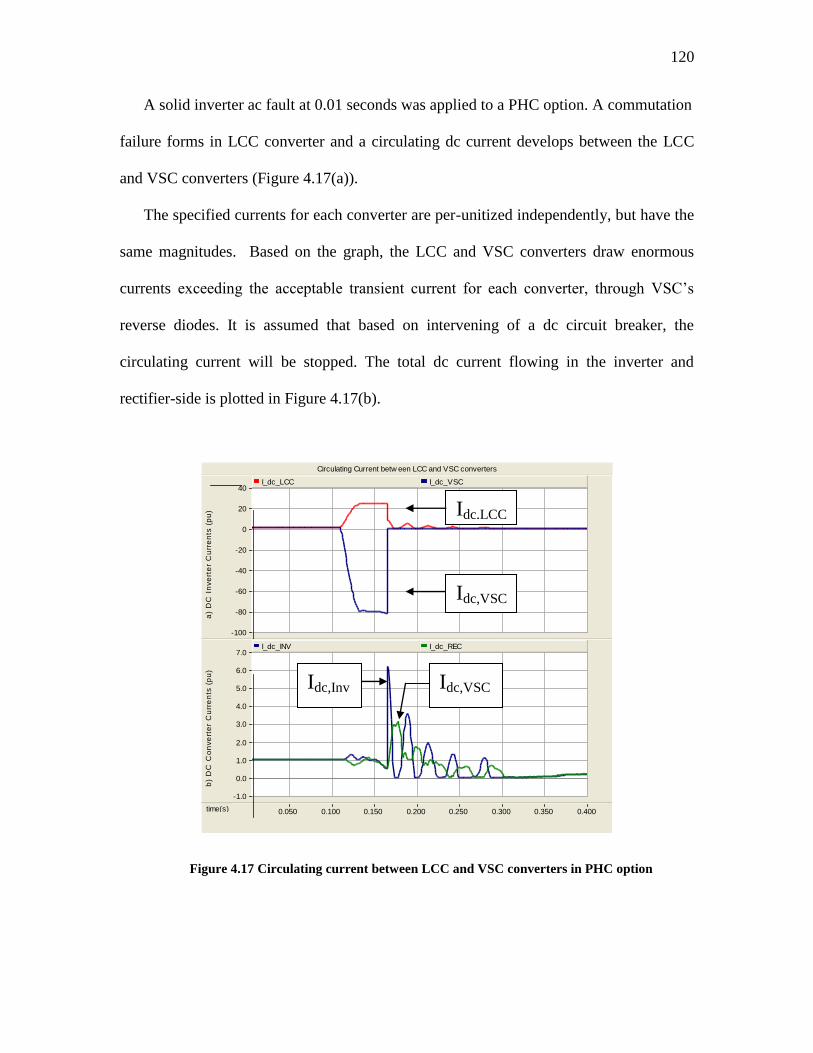
120
A solid inverter ac fault at 0.01 seconds was applied to a PHC option. A commutation
failure forms in LCC converter and a circulating dc current develops between the LCC
and VSC converters (Figure 4.17(a)).
The specified currents for each converter are per-unitized independently, but have the
same magnitudes. Based on the graph, the LCC and VSC converters draw enormous
currents exceeding the acceptable transient current for each converter, through VSC‟s
reverse diodes. It is assumed that based on intervening of a dc circuit breaker, the
circulating current will be stopped. The total dc current flowing in the inverter and
rectifier-side is plotted in Figure 4.17(b).
Circulating Current betw een LCC and VSC converters
time(s) 0.050 0.100 0.150 0.200 0.250 0.300 0.350 0.400 ...
...
...
-100
-80
-60
-40
-20
0
20
40
a
) D
C I
nve
rte
r C
urr
en
ts (
pu
)
I_dc_LCC I_dc_VSC
-1.0
0.0
1.0
2.0
3.0
4.0
5.0
6.0
7.0
b
) D
C C
on
ve
rte
r C
urr
en
ts (
pu
)
I_dc_INV I_dc_REC
Figure 4.17 Circulating current between LCC and VSC converters in PHC option
Idc,LCC
Idc,VSC
Idc,VSC
Idc,Inv
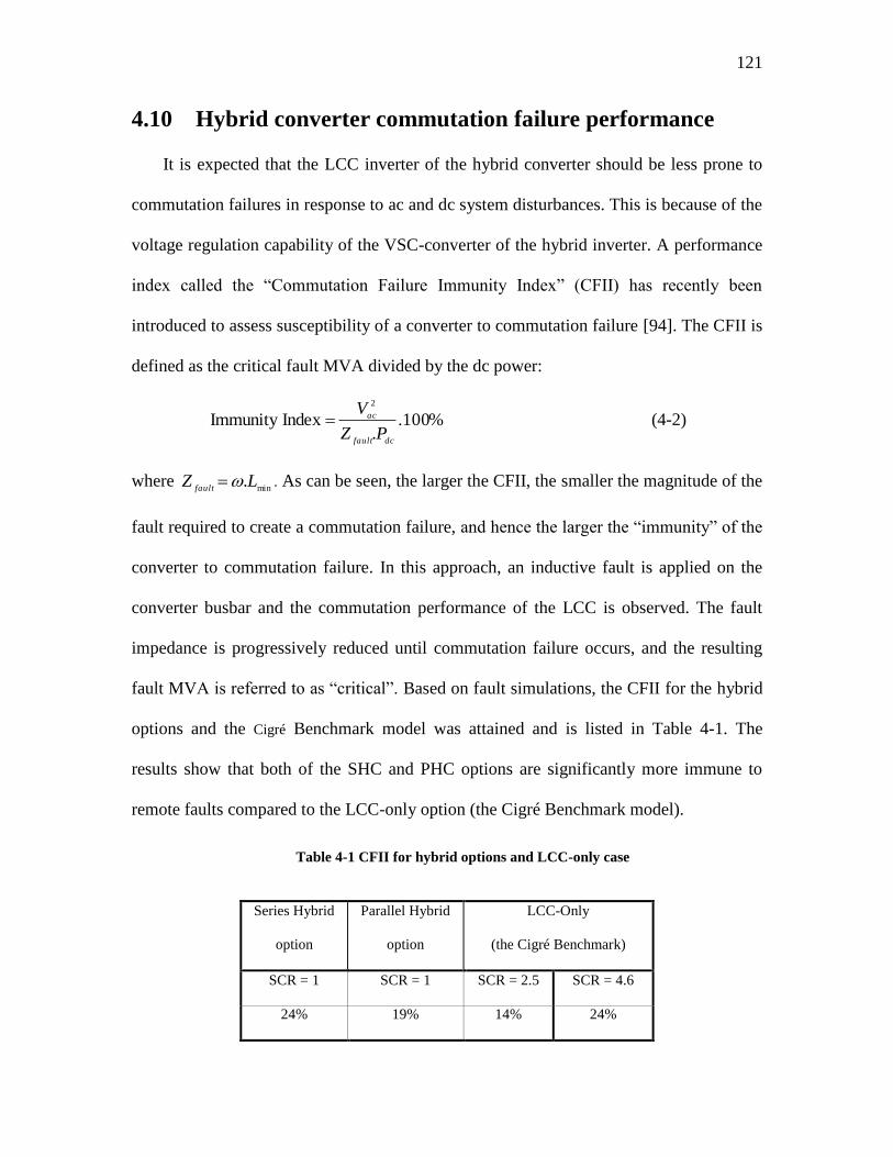
121
4.10 Hybrid converter commutation failure performance
It is expected that the LCC inverter of the hybrid converter should be less prone to
commutation failures in response to ac and dc system disturbances. This is because of the
voltage regulation capability of the VSC-converter of the hybrid inverter. A performance
index called the “Commutation Failure Immunity Index” (CFII) has recently been
introduced to assess susceptibility of a converter to commutation failure [94]. The CFII is
defined as the critical fault MVA divided by the dc power:
%100..
Index Immunity 2
dcfault
ac
PZ
V (4-2)
where min
.LZfault
. As can be seen, the larger the CFII, the smaller the magnitude of the
fault required to create a commutation failure, and hence the larger the “immunity” of the
converter to commutation failure. In this approach, an inductive fault is applied on the
converter busbar and the commutation performance of the LCC is observed. The fault
impedance is progressively reduced until commutation failure occurs, and the resulting
fault MVA is referred to as “critical”. Based on fault simulations, the CFII for the hybrid
options and the Cigré Benchmark model was attained and is listed in Table 4-1. The
results show that both of the SHC and PHC options are significantly more immune to
remote faults compared to the LCC-only option (the Cigré Benchmark model).
Table 4-1 CFII for hybrid options and LCC-only case
Series Hybrid
option
Parallel Hybrid
option
LCC-Only
(the Cigré Benchmark)
SCR = 1 SCR = 1 SCR = 2.5 SCR = 4.6
24% 19% 14% 24%

122
For further comparison, the Cigré Benchmark (LCC-only case) was modified. To do
this the SCR of the inverter system was increased until the immunity index of the LCC-
only option, was the same as the SHC‟s immunity index. The resultant SCR value was
4.6.
Hence, it can be concluded that in spite of this fact that both of the hybrid options are
extremely weak ac systems (SCR = 1), the hybrid options are able to attain a high level of
immunity against commutation failure; whereas the LCC-only option would require a far
stronger system (SCR = 4.6) to provide comparable performance.
4.11 VSC converters overcurrent protection
The LCC-based options have high over-current tolerance. They could be protected
against fault-initiated over voltages using surge arresters, which is a normal procedure in
HVdc converters. The VSC-based converters, on the other hand, cannot handle over-
currents easily. A logic-circuit based method is developed and implemented here that
protects the IGBT valves against overcurrent. This circuit has been implemented in both
the series and parallel hybrid options. The description of how the method works is as
follows.
The instantaneous ac phase current of VSC is compared with a reference value. If
magnitude of this current is not exceeding the maximum allowed value, no corrective
action is taken. If the instantaneous ac current exceeds the maximum allowed value, the
IGBT valves for the corresponding phase are ordered to switch their state, i.e. if the valve
is conducting it is switched off, and vice versa. Now because the conducting IGBT is
substituted with an IGBT on the opposite leg of the same phase, the current on that phase
is limited. The corresponding PSCAD logic circuit drawing is given in Figure D-3.
Chapter 5: Concluding Remarks
5.1 Introduction
The contribution of this thesis is the demonstration of the feasibility of VSC-LCC
hybrid converter arrangements for High Voltage direct current (HVdc) transmission
systems in stations where support of ac voltage is mostly absent (very weak ac system). A
feasibility study performs the analysis, and provides the information to help decision
making for applicability of a proposed scenario.
In this thesis, a new approach is proposed in which hybrid configuration of VSC
(Voltage Source Converter) and LCC (Line Commutated Converter) have been used.
These hybrids are arranged in two separate forms of series and parallel connection of one
VSC, and one conventional LCC converter.
Conventional converter technology (LCC) requires stiff ac voltage and enormous
amounts of reactive power at the point of common coupling to operate; VSC converter-
based HVdc schemes, on the other hand, maintain most of the advantages of conventional
LCC-based systems. They have overcome a number of disadvantages inherent to
conventional LCC systems. Their ability to provide voltage support to very weak ac
networks through generating reactive power, while delivering real power, makes them an
ideal option for providing reliable power to remote locations. On the other hand VSC
converters suffer disadvantages such as higher costs, sensitivity to dc-side faults, higher
losses, and smaller ratings in comparison to conventional converters.
Based on the appropriate control methods employed, combined with well tuned
controller parameters, the proposed hybrid converters combine the advantages of
124
individual VSC and LCC converters. At the same time, these new arrangements cover the
disadvantages of using each converter individually.
In this thesis, simplified mathematical models and extensive effort on digital time
domain simulation with PSCAD / EMTDC program is chosen as the method to tackle the
achievability of the proposed hybrid converters.
Simulation results demonstrate the feasibility of employing series hybrid converters.
This thesis concludes that the SHC configuration is a promising option to operate into a
very weak ac system. Here, the VSC converter provides both the real power, and reactive
power.
This thesis also concludes that based on Parallel Hybrid Converter‟s poor dynamic
performance and its intrinsic drawback of responding to dc and inverter-side ac faults, its
application for transferring real power in very weak ac system conditions is not
recommended.
In this chapter first the hybrid applications are discussed. Then in the following
sections the performed tasks of the thesis is highlighted. Finally main contribution of the
thesis and the recommended future directions are discussed.
5.2 Hybrid converter applications
Based on the investigations done in this thesis, the following possible applications
for the proposed series and parallel hybrid converters can be categorized.
5.2.1 Using hybrid converters in a new HVdc design
A hybrid converter system can be used in a new HVdc transmission system:
125
In a new design, the dc system electrical parameters can be set first. In this case, the
power rating of the VSC and LCC converters can be calculated optimally. Based on that,
the most suitable voltage/current rating for each converter can be allocated. The hybrid-
side electrical system can be connected to a very weak ac system.
5.2.2 Using hybrid converters as an upgrade in an HVdc design
Hybrid converters can be used as an upgrade in an existing LCC-only HVdc system:
The upgrading can be done through the addition of a VSC unit; the VSC unit can be used
to increase the level of transmitted power without the addition of extra filters or reactive
power sources, as would have been required with a conventional LCC-upgrade. The two
possible options are:
Using the SHC topology to upgrade the converter voltage level by retrofitting
a VSC in series connection with a working LCC converter. This requires
upgrading of the dc side voltage rating of the dc transmission system.
Using the PHC topology to upgrade the converter current level by retrofitting
a VSC in parallel connection with a working LCC converter. This requires
upgrading of the dc side current rating of the dc transmission system.
To upgrade an HVdc system that is already operating based on LCC-converter
technology there are limitations on retrofitting a series, or parallel VSC converter. Most
of these limitations emerge because of the existing level of voltages / and or currents
available in the system, which might not be possible to change. Under such
circumstances, using the proposed optimization scenario for selecting the optimal power,
and allocating appropriate voltages (or currents) might not be possible. As such, most
probably the retrofitted VSC cannot have optimally selected ratings.
126
5.2.3 Substituting part of a HVdc system with a hybrid converter
Part of an LCC-based HVdc system can be substituted with a VSC converter:
There are parallel connected LCC converters already working in HVdc transmission
systems. With decreasing trend seen in IGBT component prices, the VSC converters may
be substituted by one LCC converter that has to be pulled off permanently from
operation. One example of that could be retiring of one of the two LCC converter bi-
poles in Manitoba province that are working in parallel, and substituting one of them with
a VSC converter.
Paralleling a VSC converter with a conventional LCC converter, which forms a PHC
converter, has already been discussed in this thesis. When dc breakers are commercially
available to stop successfully the dc fault and inverter ac faults, a PHC might be an
option. If the PHC is not serving a very weak ac system, this configuration might
demonstrate acceptable dynamic performance. It must be stressed that as a finding of this
thesis, the PHC application is not recommended for supplying a very weak ac electrical
system.
5.3 Highlight of the performed tasks
This section highlights and discusses the performed tasks during this research. These
include:
Hybrid VSC–LCC converters in two configurations of series (SHC) and parallel
(PHC) were proposed.
A new optimization concept was introduced. In this optimization a suitable
proportion of voltage between VSC and LCC converters for the SHC option, and
a suitable proportion of current between the VSC and LCC converters for the
127
PHC option can be allocated. Upon using this concept, the most appropriate
voltage and current levels for the corresponding hybrid converters can be
obtained.
Control methods necessary for system operation were distinguished and
implemented successfully.
Hybrid systems under very low short circuit ration conditions (SCR = 1) were
simulated.
System dynamic response to step changes in operational set points, and system
dynamic response to different large disturbances under SCR = 1 were investigated
and compared with the Cigré Benchmark model responses.
The commutation failure immunity level of hybrid converters was calculated and
compared with the Cigré Benchmark model.
A logic circuit based method was proposed to protect VSC switches from over
currents.
5.4 Conclusions and findings of the research
The conclusions and findings of this research are:
The hybrid VSC-LCC converters are capable of working under very weak ac
system conditions. As conventional LCC converters need stiff voltage to be able
to operate under such conditions, they do not represent possible candidates to
work under such circumstances.
Hybrid options:
128
Provide excellent voltage support at the inverter terminal, even under very
weak ac system conditions. As the conventional LCC converters need
such support, they cannot be used individually under such circumstances.
Demonstrate excellent small dynamic response to step changes applied in
terminal real power and rectifier dc current order.
Demonstrate very good response to short circuit ratio changes.
Have low-overshoot response to full inverter load rejection, with zero
steady-state overvoltage. It is concluded that regarding overvoltage, the
hybrid converters have superior performance, even when they are
connected to very weak ac systems.
Under very low short circuit ratios (SCR = 1) show very competitive
dynamic performance compared to conventional LCC converters working
under higher short circuit ratios (SCR = 2.5).
Exhibit much higher commutation failure immunity index (CFII) under
equal short circuit ratio conditions. This means that hybrid options are less
sensitive to remote faults. As a result the chances of commutation failure
in the proposed hybrid converters are generally much less than the
conventional LCC converters.
Show less sensitivity to single-phase faults, compared to LCC-only option.
SHC option is a promising solution for feeding high power to very weak ac
systems. The VSC can deliver an optimally-calculated real power share.
129
PHC option is not a good candidate to work under very weak ac system
conditions. This is because of its poor dynamic performance and its intrinsic
drawback of responding to a group of faults.
5.4.1 Advantages of using the proposed hybrid converters
Based on the simulation results the series hybrid converters possess the following
advantages, compared to the LCC-only converters. They demonstrate:
fast and well-damped response to power step, and rectifier current order changes
less chance of total power disruption
less inverter terminal voltage disturbances compared to conventional LCC
converters
less overall system impact during faults
less sensitivity to single phase-to-ground faults
operating under de-rated mode when LCC inverter has failed to operate
generally much less susceptibility to commutation failure following ac rectifier
faults compared to conventional LCC converters
having higher commutation failure immunity index (CFII)
5.4.2 Disadvantages of using the proposed hybrid converter options
Based on the simulation results the parallel hybrid converter suffers from an intrinsic
drawback that during ac inverter-side faults, or dc faults, the fault current cannot be easily
interrupted and demonstrates long power recovery time. It has also generally poorer
dynamic performance compared to LCC-only converters.
Other weaknesses of the proposed hybrid options are:
130
Changing the direction of power flow in hybrid options is complicated and may
need complete shutdown; shutting down itself depends on the method used.
To shift the low order harmonic content to higher frequencies and avoid using
expensive low-order harmonic filters, the switching frequency of forced
commutating components must be selected high, which causes higher power
losses during the switching times.
They need at least one more transformer compared to the LCC-only converters.
5.5 Main contributions of the thesis
The followings are considered the key contributions of this thesis:
A series hybrid converter composed from series connection of one VSC and one
LCC converter was proposed, designed and simulated. It is shown that this
converter is capable of operating into an electric system with very short circuit
ratio (SCR = 1), where VSC has also power generation capability. The power
rating of the converters and the appropriate proportion of the voltages between the
converters was also allocated.
A parallel hybrid converter composed from parallel connection of one VSC and
one LCC converter was proposed, designed and simulated. It is shown that this
converter is capable of operating into an electric system with very short circuit
ratio (SCR = 1), where VSC has also power generation capability. The power
rating of the converters and the appropriate proportion of the currents between the
converters was also allocated.
131
It is shown that both of the hybrid converter options provide higher commutation
failure immunity index (CFII) compared to LCC-only converters. To have
identical CFII, the LCC-only option needs to have considerably higher SCR.
Technical feasibility of the SHC converters is demonstrated. It is concluded that
the SHC option is a promising solution for feeding high power to very weak ac
electric systems.
Intrinsic drawback of the PHC converters is demonstrated. It is concluded that the
PHC option is not a good candidate to work under very weak ac system
conditions. This is because of its poor dynamic performance and its intrinsic
drawback of responding to a group of faults.
5.6 Further recommendations for future work
The main concern of this study is demonstrating the feasibility of series and parallel
hybrid converters. As a direct result of this, the controller parameters in simulated system
have not been optimized in a global sense. Based on the results obtained, the following
directions are proposed:
Major tasks:
Using Manitoba HVdc system data to fully investigate the chance of
substituting one of the conventional converter-based bi-poles with a VSC
based inverter (PHC option)
Deriving a small signal model for SHC, and PHC hybrid options. This lets
finer tuning of the controller parameters
Assessing the feasibility of connecting SHC and PHC hybrid converters to a
dead system
132
Analyzing a multi-terminal HVdc system, based on a hybrid HVdc system in
parallel with a LCC-only based system
Minor tasks:
Performing an economical assessment of the hybrid converter
Optimizing the VSC‟s dc capacitor size
References:
[1] Arrillaga, J., “High Voltage Direct Current Transmission”, IEE Power Engineering
Series, 1998.
[2] Gavrilovic, A., “AC/DC system strength as indicated by short circuit ratios”, IEE
Fifth International Conference on AC and DC Power Transmission, London,
September 1991, pp: 27 -32
[3] Cigré Working Group 14.07 (AC/DC System Interaction), “Guide for Planning DC
links Terminating at AC Systems Locations Having Low Short-Circuit Capacities”,
Part I, June 1992.
[4] Kimbark, E.W., “Direct Current Transmission”, Vol. 1, John Wiley & Sons Inc.,
1970
[5] Sood, V. K., HVdc and FACTS controllers, Kluwer Academic Publishers, 2004
[6] Andersen, B. R. “Voltage Sourced Converters”, Cigré report, B4-37, 2003
[7] Monsur, N., Sood, V.K., Lopes, L.,“Modelling a hybrid diode-thyristor HVdc
rectifier in EMTP-RV”, Canadian Conference on Electrical and Computer
Engineering, 2006
[8] Ainsworth J.D., Gavrilovic A., and Thanawala H. L., “Static and synchronous
compensators for dc transmission connected to weak ac systems“, Cigré 28th General
Session, 1980, Paris, France, Paper 31-0
[9] Nayak O. B., Golé A.M., Chapman D.G., Davies J.B., “Dynamic performance of
static and synchronous compensators at an HVdc inverter bus in a very weak ac
system”, IEEE Transaction on Power Systems, Vol. 9, No.3, Aug. 1994, pp. 1350-
1358
[10] Zhuang Y., Menzies R.W., Nayak O.B., Turanli H. M., “Dynamic performance
of a STATCON at an HVdc feeding a very weak AC system”, IEEE Transaction on
Power Delivery, Vol. 11, April 1996, pp. 958-964
[11] Wachal, R.W., Mazur G.B., Golé A.M., Whitehouse R.S., “Application of
electromagnetic transient simulation for the solution of HVdc control problem”,
IEEE Conf. Proceedings in Communications, Power and Computing, vol. 2, 15-16,
May 1995, pp. 283 – 288
[12] Manitoba HVdc Research Centre,“EMTDC User’s Manual”, Winnipeg, MB,
Canada, 2007
[13] Rudervall, R., Charpentier, J. P., Sharma, R., “High Voltage direct current
(HVdc) Transmission Systems”, Technical Review Paper, Presented at Energy Week,
Washington D.C., March 7-8, 2000
[14] IEC 60633:1998 - “Terminology for High Voltage direct current (HVdc)
transmission”
134
[15] Meah K., Ula S., “Comparative Evaluation of HVdc and HVac Transmission
Systems”, Power Engineering Society, 2007, pp. 1-5
[16] Vancers, I., Christoferson, D. J., Leirbukt, A., Bennet, M. G., “A survey of the
reliability of HVdc systems through the world during 1999-2000”, Cigré 2002 paper
No. 14-101, 2002.
[17] Burton R.S., Fuchshuber C.F,. Woodford D.A, Golé A.M., “Prediction of Core
Saturation Instability at an HVdc Converter”, Power Engineering Review, IEE, Vol.
11, Issue 4, Oct. 1996, pp. 1961-1969, Digital Object Identifier 10.1109/61.544283
[18] Krishnayya P.C.S., Piwko, R.J., Weaver, T.L., Bahrman, M.P.and Hammand,
A.E., “DC transmission terminating at Low Short Circuit Ratio locations”, IEEE,
Trans. On Power Delivery, Vol. PWRD-1 No. 3, July 1986, pp. 308-317
[19] Hammad, A.E., Kuhn, W.E., “A computer algorithm for assessing voltage
stability at AC/ DC interconnections”, IEEE Trans. On Power Systems, Vol. PWRS-
1, No. 1, Feb. 1986, pp. 209-216
[20] Gavrilovich, A., et. el. “Aspects of AC/DC system interaction: peak available
power, second harmonic resonance, low inertia systems, controllability of HVdc”,
Montreal‟86, Montreal, Canada.
[21] Hingorani, N.G., Nilsson, S.L., Pohl, R.V., Gund, C.E., Cresap, L., “Active and
reactive power modulation of HVdc system’, Proceeding of the IEEE conference on
Over voltages and compensation in integrated AC-DC systems, Winnipeg, July 1980
[22] Szechman, M., Wess, T., and Thio, C.V., "First Benchmark model for HVdc
control studies", Cigré WG 14.02 Electra No. 135 April 1991 pp: 54-73.
[23] “Working group on dynamic performance and modeling of DC systems and
power electronics for transmission systems”, Report on test systems for AC/DC
interaction studies, IEEE Trans, 1995, PD-10, (4), pp. 2027-2034
[24] Jovcic, D., Pahalawaththa, N., Zavahir, M., “Inverter controller for HVdc systems
connected to weak AC systems”, Generation, Transmission and Distribution, IEE
Proceedings, Vol. 146, Issue 3, May 1999, pp. 235-240
[25] Gagnon, J., Venne, A., Henderson, M.I., Tammar, K., “Operating Experience
with the Chateauguay HVdc tie”, Proceedings from the IEEE Panel Session on
Operating Experience of DC Systems interacting With Weak AC Systems. IEEE 91
THO 420-0 PWR pp 1-9.
[26] Lindberg, A., “PWM and control of two and three level high power voltage
source converters”, The Royal Institute of Technology, Stockholm, 1995.
[27] McMurray, W., “Feasibility of Gate turn off thyristors in an HVdc transmission
system”, EPRI EL-5332, Final Report, August 1987
[28] McMurray, W., Mehta, H., “Feasibility of GTOs in HVdc systems”, paper
presented at the IEEE / PES 1988 meeting, Portland, Oregon, July 24-29, 1988
135
[29] Yamada, H., Sampei, M., Kashiwazaki, H., Tanaka, C., Takahashi, T., Horiuchi,
T., “GTO thyristor application for HVdc transmission system”, IEEE Tran. On
Power Delivery , Vol. PWRD-5, No. 3 , pp. 1327-1335 , 1990
[30] Zhang, G., Xu, Z., Zheng, Liu, Hongtao, “Supply passive networks with VSC-
HVdc”, Proceedings, IEEE Engineering Society Transmission and Distribution
Conference, vol. 1, Summer 2001, pp. 332-331
[31] Eriksson, K., “Operational experience of HVdc Light”, AC-DC Power
transmission, 2001, Seventh International Conference on, Pub. No.485, 28-30, Nov.
2001, pp. 205 – 210
[32] Asplund, G.; “Application of HVdc Light to power system enhancement”,
Power Engineering Society Winter Meeting, 2000. IEEE, Vol. 4, 23-27 Jan. 2000 ,
pp. 2498 - 2503
[33] Schettler F., Huang H., and Christl N., “HVdc transmission systems using voltage
sourced converters, design and applications”, in IEEE power Engineering Society,
2001
[34] Takasaki, M. Gibo, N. Hayashi, T., “Evaluation of the relation between voltage
sourced converter performance and design parameters”, IEE conference
publications, No. 485, 2002, pp. 96-101
[35] Konishi, H., Takahashi, C., Kishibe, H., Sato, H.,”A consideration of stable
operating power limits in VSC-HVdc systems”, IEE Conference publication, No.,
485, 2002, pp. 102-106
[36] Huang, Z., Ooi, B. T., “Power transfer capability of long transmission lines with
midpoint sited FACTS and HVdc”, IEEE Power Engineering Review, Vol. 22, No. 5,
May 2002, pp. 51-53
[37] Poullain, S., Heliodore, F. Henni, A. Thomas, J.L. Courbon, E., “Modeling
of the dynamic characteristics of the DC line for VSC transmission scheme”,
AC-DC Power Transmission, 2001, Seventh International Conference on, Pub. No.
485, 28-30 Nov. 2001, pp. 305 - 310
[38] Kosterev, D. N., “Modeling synchronous voltage source converters in
transmission system planning studies”, IEEE Transactions on Power Delivery, vol. 1,
no. 2, Apr. 1997, pp. 947-952
[39] Lehn, P.W., Iravani, M.R., “Discrete time modeling and control of the voltage
source converter for improved system disturbance rejection”, IEEE Transaction on
Power Electronics, vol. 14, no. 6, Nov. 1999, pp. 1028-1036
[40] Zhang, G., Xu, Z., Cai, Y., “An equivalent model for simulating VSC based
HVdc“, Proceedings, IEEE Power Engineering Society Transmission and Distribution
Conference, vol. 1, 2001, pp. 20-24
[41] Lehn, P.W., “Exact modeling of the voltage source converter”, IEEE Transaction
on Power Delivery, vol. 17, no. 1, Jan., 2002, pp. 217-222
136
[42] Schettler, F., Huang, H., Christl, N., “HVdc transmission systems using Voltage
Sourced Converters: Design and Application”, Conference Proceedings, IEEE
Summer Meeting 2000, Paper No. 2000SM-260, Vol. 2, pp. 716-720
[43] Nakajima, T.; Suzuki, H.; Izumi, K.; Sugimoto, S.; Yonezawa, H.; Tsubota,
Y.;”A converter transformer with series-connected line-side windings for a DC link
using voltage source converters”, Power Engineering Society 1999 Winter Meeting,
IEEE , Volume: 2 , 31 Jan-4 Feb 1999 , pp.1073 - 1078
[44] Zhang, G., “Steady-state model for VSC based HVdc and its controller design”,
Power Engineering Society Winter Meeting, 2001. IEEE , vol. 3 , 28 Jan.-1 Feb.
2001, pp. 1085 -1090
[45] Lu., B.; Ooi., B. T., “Unified power flow controller (UPFC) under nonlinear
control”, Power Conversion Conference, PCC Osaka 2002, Proceedings of the, vol.
3, 2-5 April 2002 , pp. 1118 - 1123
[46] Ying, J., “Active and reactive power control for transmission systems with
voltage source converters”, Thesis, KTH Royal Institute of Technology, 1999
[47] Du, C., “VSC-HVdc for industrial power systems”, Chalmers University of
Technology, Sweden, 2007
[48] Zhao, Z., Iravani, M.R., “Application of GTO voltage-source inverter for tapping
HVdc power”, Dept. of Electrical Engineering, Toronto Univ., Ont.; IEE proceedings,
Generation, Transmission and Distribution, Jan. 1994
[49] Karlecik-Maier, F., “A new Closed Loop Control method for HVdc transmission”,
IEEE Trans. on Power delivery, Vol. 11, no 4, October 1996. pp. 1995-1960.
[50] Suzuki, H.; Nakajima, T.; Izumi, K.; Sugimoto, S.; Mino, Y.; Abe, H,
“Development and testing of prototype models for a high-performance 300 MW self-
commutated AC/DC converter“, Power Delivery, IEEE Transactions on , vol. 12
Issue: 4 , Oct. 1997, pp. 1589 -1601
[51] Zhao, Z., “HVdc applications of GTO Voltage Source Inverters”, PHD Thesis,
University of Toronto, 1993
[52] Iwata, Y., Tanaka, S., et. al., “Simulation study of a hybrid HVdc system
composed of a self-commutated converter and a Line commutated converter”, AC
and DC power transmission, Conference publication paper, publication No., 423, IEE,
1996
[53] Busemann, F., “Economic Supply of Reactive Power for Inverter Stations”,
Direct Current, June 1954, pp. 8-15.
[54] Reeve, J., Baron J.A., and Hanley, G.A., “A Technical Assessment of Artificial
Commutation of HVdc Converters”, IEEE Trans. PAS, Vol. PAS-87, No. 10, pp.
1830-1840, Oct. 1968.
[55] Golé, A.M., and Menzies, R.W., “Analysis of Certain Aspects of Forced
Commutated HVdc Inverters”, IEEE Transactions PAS, Vol. PAS-100, No. 5, pp.
2258-2262, May 1981.
137
[56] Sadek, K., Pereira, M., Brandt, D.P., Golé, A.M., Daneshpooy, A., “Capacitor
Commutated Converter Circuit Configurations For Dc Transmission”, IEEE
Transactions on Power Delivery, vol. 13, No. 4, pp. 1257-1264, October 1998.
[57] Meisingset, M., “Application of capacitor commutated converters in multi-infeed
HVdc-schemes”, PH.D. Thesis, The University of Manitoba, Winnipeg, May, 2000
[58] Ekström, Å., “High Power Electronics HVdc and SVC”, The Royal Institute of
Technology, Stockholm, 1990.
[59] Jiang, H., Ekström, Å., “Harmonic cancellation of a hybrid converter”
Power Delivery, IEEE Transactions, vol. 13, Issue: 4, Oct. 1998, pp.1291 – 1296
[60] Gonzalez, J. W., Weindlt, C., Heroldt, G., Retzmanntt, D., Cardona, H. A., Isaac,
I. A., and Lopez, G. L., “Feasibility of HVdc for Very Weak AC Systems with SCR
below 1.5”, IEEE, EPE-EPMC, 2006
[61] Fukuda, S.; Kubo, Y.; Kitano, M., “Introduction of a hybrid multi-converter
system and its control strategy“, Power Conversion Conference, 2002. PCC Osaka
2002, Proceedings, vol. 2, 2-5, April 2002, pp. 372 -377
[62] Andersen, B. R., Xu, L., Cartwright, P., “Hybrid HVdc for the supply of power to
offshore oil platforms”, Cigré report, B4-304, 2004
[63] Hammad A., Sadek K., Koelsch H., Gueth G., “Advanced scheme for AC voltage
control at HVdc converter terminal”, IEEE Trans., 1985, PAS-104, (3), pp. 697-703
[64] Kim, C.K., Sood, V.K., Jang, G.S., Lim, S.J., Lee, S.,J., “HVdc Transmission,
Power Conversion Applications in Power Systems”, John Wiley and Sons Ltd., 2009
[65] Mohan, N., Undeland, T.M. and Robbins, W.P., “Power Electronics: Converters,
Applications and Design”, John Wiley & Sons Inc., 1995
[66] M. Avram; G. Brezeanu; A. Avram; O. Neagoe; M. Brezeanu; C. Iliescu; C.
Codreanu; C. Voitincu, “Contributions to development of high power SiC-IGBT”,
Semiconductor Conference, 2005. International CAS 2005 Proceedings, 2005
vol.2, Issue, 5-5 Oct. 2005, pp. 365 – 368
[67] Donahue, J.A., Griggs, E.B., Lorden, D.J., “Operating Experience of the
Comerford DC Converter Station”, Proceedings from the IEEE Panel Session on
Operating Experience of DC Systems interacting with Weak AC Systems, IEEE 91
THO, 420-0 PWR, pp 52-58.
[68] IEEE Standard 519-1992, Revision of IEEE Std. 519-1981, “IEEE Recommended
practices and requirements for harmonic control in Electrical Power Systems”.
[69] Szechtman, M., Ping, W.W., Salgado, E., Bowles, J.P., “Unconventional HVdc
control technique for stabilization of a weak power system”, IEEE Trans on PAS, vol.
PAS-103, no 8, August 1984, pp. 344-349
[70] Ainsworth, J.D., “Power limit instability, voltage instability in an HVdc link
connected to weak AC system”, Cigré SC14 Colloquium, 1985
[71] Cigré, “AC/DC interaction phenomena, Dec. 1991
138
[72] Franken, B., “An analysis of HVdc in weak AC systems”, EKC, electric Power
Research Center, Stockholm, 1989
[73] Ainsworth, J.D., “Harmonic instability between controlled static converters”,
Proc. IEE, vol. 114, No. 7, July, 1967
[74] Nayak O.B., Golé A.M., Chapman D.G., and Davies J.B., "Control Sensitivity
Indices for Stability Analysis of HVDC Systems", IEEE Transactions on Power
Delivery, vol. 10, No. 4, October 1995, pp. 2054-2060.
[75] Lescale, V. F., Åström, U., Ma, W., Liu, “The Xiangjiaba-Shanghai 800 kV
UHVDC project status and special aspects”, B4-102-2010, Cigré Session 43, 2010,
Paris
[76] Cigré Brochure 185, “Modeling new forms of generation and storage”, Task
force 38.01.10, April 2001
[77] Jiang-Hafner, Y.; Hyttinen, M.; Paajarvi, B., “On the short circuit current
contribution of HVdc Light”, Transmission and Distribution Conference and
Exhibition 2002, Asia Pacific. IEEE/PES, vol. 3, 6-10 Oct. 2002, pp.1926 -1932
[78] Reed, G., Pape, R., Takeda, M., ”Advantages of voltage sourced converter (VSC)
based design concepts for FACTS and HVdc-link applications”, Power Engineering
Society General Meeting, 2003, IEEE ,vol.3 , July 2003, pp. 1821-1827
[79] Westerweller, T., Friedrich, K., Armonies, U., “Trans bay cable – world's first
HVDC system using multilevel voltage-sourced converter’,B4-101-2010, Cigré
Session 43, 2010, Paris
[80] Woodford, D., A. “HVdc transmission”, Technical report, Manitoba HVdc
Research Centre, 1998
[81] Li, L., Czarkowski, D., Pillay, P., “Multilevel Selective Harmonic Elimination
PWM Technique in Series-Connected Voltage Inverters”, IEEE Transactions on
Industry Applications, vol. 36, no. 1, January/February 2000
[82] Boost, M.,A., Ziogas, P.,D., “State of the art carrier PWM techniques: A critical
evaluation”, IEEE Transactions on Industry Applications, vol. 24, No. 2, pp. 271-
280, March / April 1988
[83] Enjeti, P.,N., Ziogas, P.,D., and Lindsay, J.,F., “Programmed PWM techniques to
eliminate harmonics, A critical evaluation”, IEEE Transactions on Industrial
Applications, IA-26, No. 2, March / April 1990, pp. 302-316
[84] Schauder, C., Mehta, H., “Vector analysis and control of advanced static VAR
compensators”, Generation, Transmission and Distribution, IEE Proceedings, vol.
140, Issue No.4 , July 1993 , pp 299 – 306
[85] Qahraman, B., Rahimi, E., Golé, A.M. “An electromagnetic transient simulation
model for voltage sourced converter based HVdc transmission”, CCECE2004, May
2004
139
[86] Qahraman, B., Golé, A.M., and Fernando, I.T., “Hybrid HVDC converters and
their impact on power system dynamic performance”, Power Engineering Society
General Meeting, 18-22 June, 2006, Canada
[87] Qahraman, B., Golé, A.M., “A VSC based series hybrid converter for HVDC
transmission”, CCECE 2005, pp. 458-461
[88] Cigré WG 14.30, “Guide to the specification and design of ac filters for HVDC
systems”, 1998.
[89] Osauskas, C.; Wood, “A Small-signal dynamic modeling of HVdc systems”,
Power Delivery on IEEE Transactions, vol.18, Issue: 1, Jan 2003, pp. 220 -225
[90] Golé, A.M., Sood, V.K. and Mootoosamy L.,“Validation and Analysis of a Grid
Control System using d-q-z Transformation for Static Compensator Systems”,
Canadian Conference on Electrical & Computer Engineering, Proceedings pp. 745-
748, Montréal, PQ, Canada, September 17-20, 1989.
[91] Kundur, P.,“Power system stability and control”, McGraw-Hill, Inc. 1994
[92] Karlsson, T., and Liss, G.,“HVdc transmissions with extremely long dc cables
control strategies“, Proceedings of the International Symposium on Electric Power
Engineering, Stockholm Power Tech, pp. 24-29, June 1995.
[93] Filizadeh, S., Golé, A. M., Woodford, D. A., Irwin, G. D., “An Optimization-
Enabled Electromagnetic Transient Simulation-Based Methodology for HVdc
Controller Design”, IEEE Trans. on Power Delivery., vol. 22, Issue 4, pp. 2559-2566,
Oct. 2007
[94] Thio, C.V., Davies, B., Kent, K.L., "Commutation Failures in HVDC
Transmission Systems", IEEE Trans. Power Delivery, vol. 11, no. 2, April 1996.
[95] Ekström, Å., Härtel, H., Lips, H.P., Schultz,W., Joss, P., Holfeld, H., and Kind,
D., “Design and testing of an HVDC circuit-breaker”; Cigré, 1976, Session 13-06
[96] Caprivi link interconnector, ABB , http://www.abb.com/cawp/gad02181/
[97] Sobrink, K.H., Kjargaard, J. P., Rasmussen, C., Nacker, J., Rossel, R., Leutner, E.
M. Nyberg, S., “The new Storebalet HVdc project for interconnecting eastern and
western Denmark”, B4-104, Cigré 2008
[98] Melvold, J. D., “Back-to-back HVdc system performance with different smoothing
reactors”, IEEE Trans. on Power Delivery, vol. 4, no.1 , January 1989, pp. 208-215
Appendix A: Hybrid Electrical System
Design
A.1 Introduction
Allocating the appropriate voltage rating between VSC and LCC converter in series
hybrid converter and current in parallel hybrid converter topology starts with the
proposed optimization method (Section 3.6). The next step is obtaining the appropriate
required reactive power generation from harmonic filters. This selection has been
accomplished through an iterative method, based on a trade-off between minimum
reactive power needed, and the rating attained based on harmonic analysis at ac inverter
terminal (Section 3.6).
In the following sections, the transformer power rating for the hybrid options on
inverter side is calculated. The rectifier rating is as per Cigré model, given in Table C.4.
Finally the transformer voltages for the inverter side (hybrid options), and for the rectifier
side is calculated.
A.2 Determining transformer power rating for the hybrid
options
Using an iterative approach, the needed reactive power for stable operation of the
SHC hybrid inverter is found to be equal to 103 Mvar. A similar procedure results in 110
Mvar for the reactive power needs of the PHC option. Based on optimization concept
explained in section 3.6, the transformer ratings are calculated as follows. In the
following calculations, 100 Mvar is used for the SHC option.
141
Using var 100MQf , assume that LCCP represents the active LCC power and
LCCP*6.0 expresses the LCC reactive power. At the VSC converter, the active and
reactive power are, respectively:
LCCVSC PP 1000 , and fLCCVSC QPQ *6.0 . So the parametric form for the
apparent power at VSC, is:
2222 )100*6.0()1000( LCCLCCVSCVSCVSC PPQPS (A-1)
Taking the derivative of this equation and putting that equal to zero, leads to the
following VSC ratings:
MVA 428 ,Mvar 370 ,MW 220 VSCVSCVSC SQP (A-2)
Then the total LCC rating is:
MVA 914 ,Mvar 470 ,MW 784 LCCLCCLCC
SQP (A-3)
Here the conventional assumption of equal rating for each of the two LCC-inverter
converters is used. These optimized values for converter transformer ratings have been
implemented in simulating model for the SHC and PHC hybrid inverters.
A.3 Determining transformer rating for rectifier converter
Using 500 kV as the voltage on dc side of inverter and nominal current of the HVdc
system, which is kA 2500
1000
dc
dcdc
V
PI , the rectifier side parameters may be
calculated based on dc line parameters:
kV 510*500Re, dccdc IRV (A-4)
Using the basic relation between dc voltage and the fundamental voltage component of ac
side of rectifier,
142
dcCcaccdc InXVnV ...3
)cos(*..35.1 2Re,Re,
(A-5)
where is the rectifier angle, n is the transformer ratio, cacV Re, is line-to-line voltage at
rectifier‟s terminal (230 kV), dcI is the direct current, and LX is transformers leakage
reactance (0.18 p.u.), or:
818.0*1190
2302
LX (A-6)
Now,
2..8.3
)15cos(.230..34.1510 2nn
(A-7)
which leads to 86.1n . So the secondary voltage of the VSC transformer is:
kV 1.42086.1*230sec V (A-8)
The transformer rating for the rectifier side is:
Mvar 6121020*6.0 ,MW 1020201000 ReRe cc QP (A-9)
which leads to MVA 1190recS
A.4 Voltage and current calculations for hybrid options
A.4.1 Series hybrid converter
Using 500 KV as the inverter-side dc voltage ( InvV ), and using the VSCP as in (A-5),
kV 1102
220
2 VSC
VSC
PV (A-10)
Based on this number, the LCC-inverter voltage is: kV 390 LCCV
143
Based on MVA 910LCCS , or 455 MVA for each of the LCC converter
transformers in the inverter side, and assumption of 230 kV rms voltage for inverter
terminal voltage at the system side of the transformer, its reactance would be equal to:
464.1018.0*910
2302
LCCX (A-11)
To calculate the transformer rating for inverter LCC, we have:
*..3
)cos(.230..35.1 2dcLdc InXnV
(A-12)
or,
2**464.10*2*3
)180
*15cos(.230..35.12
390 2nn
(A-13)
which leads to the transformer ratio of: 722.0n , or accordingly:
kV 06.166722.0*230 primV (A-14)
In normal working conditions, the inverter works in voltage control mode,
demanding some adjustments to be made on the calculated primary (inverter) side of the
LCC converter. The adjusted voltage used in simulation is 169 kV.
Using the KV 110VSCV , the transformer voltage rating for VSC may be calculated.
Assuming a modulation index ( m ) of 8.0m , the fundamental frequency magnitude of
voltage at ac side of VSC converter equals:
kV 53.9 5.1*80.0*2
110 :or
2
3**
2 L
dcL Vm
VV (A-15)
Based on the original design assumption of 1 p.u. (230 kV) voltage at ac inverter
terminal voltage, the reactive power flow at terminal should be zero. In PSCAD
simulation, the inverter side of VSC transformer has a high harmonic content, suggesting
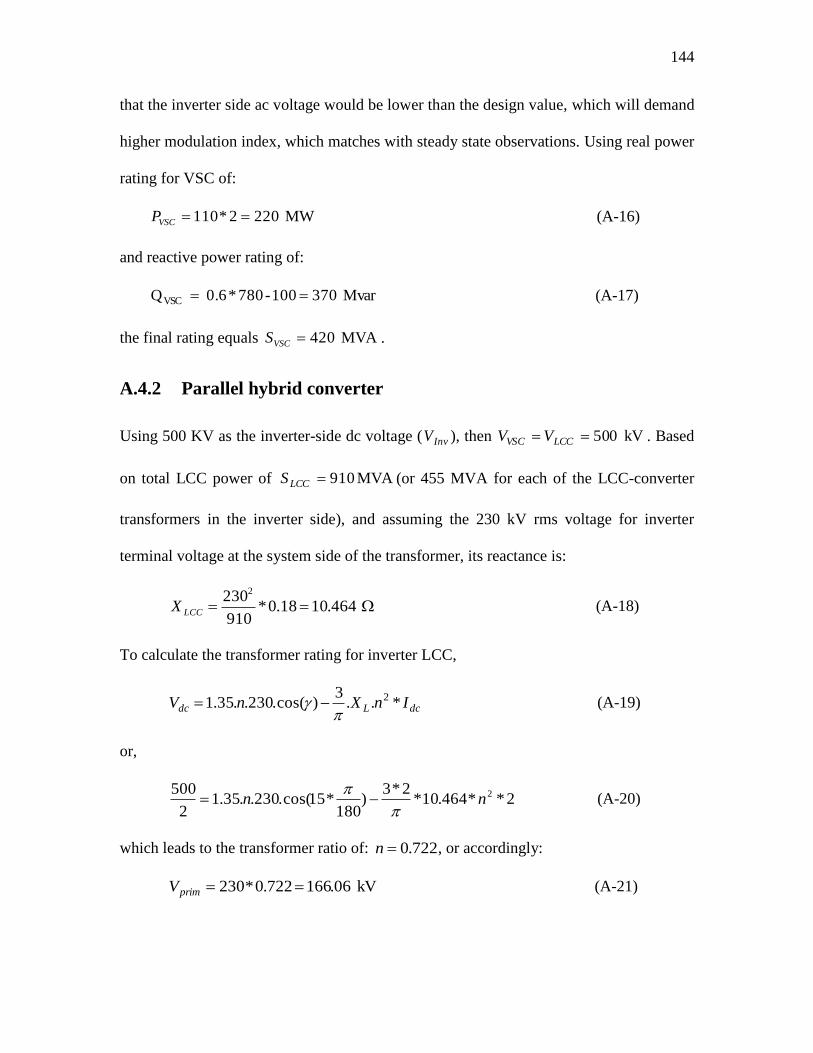
144
that the inverter side ac voltage would be lower than the design value, which will demand
higher modulation index, which matches with steady state observations. Using real power
rating for VSC of:
MW 2202*110 VSCP (A-16)
and reactive power rating of:
Mvar 370100-780*0.6 QVSC (A-17)
the final rating equals MVA 420VSCS .
A.4.2 Parallel hybrid converter
Using 500 KV as the inverter-side dc voltage ( InvV ), then kV 050 LCCVSC VV . Based
on total LCC power of MVA 910LCCS (or 455 MVA for each of the LCC-converter
transformers in the inverter side), and assuming the 230 kV rms voltage for inverter
terminal voltage at the system side of the transformer, its reactance is:
464.1018.0*910
2302
LCCX (A-18)
To calculate the transformer rating for inverter LCC,
dcLdc InXnV *..3
)cos(.230..35.1 2
(A-19)
or,
2**464.10*2*3
)180
*15cos(.230..35.12
500 2nn
(A-20)
which leads to the transformer ratio of: 722.0n , or accordingly:
kV 06.166722.0*230 primV (A-21)
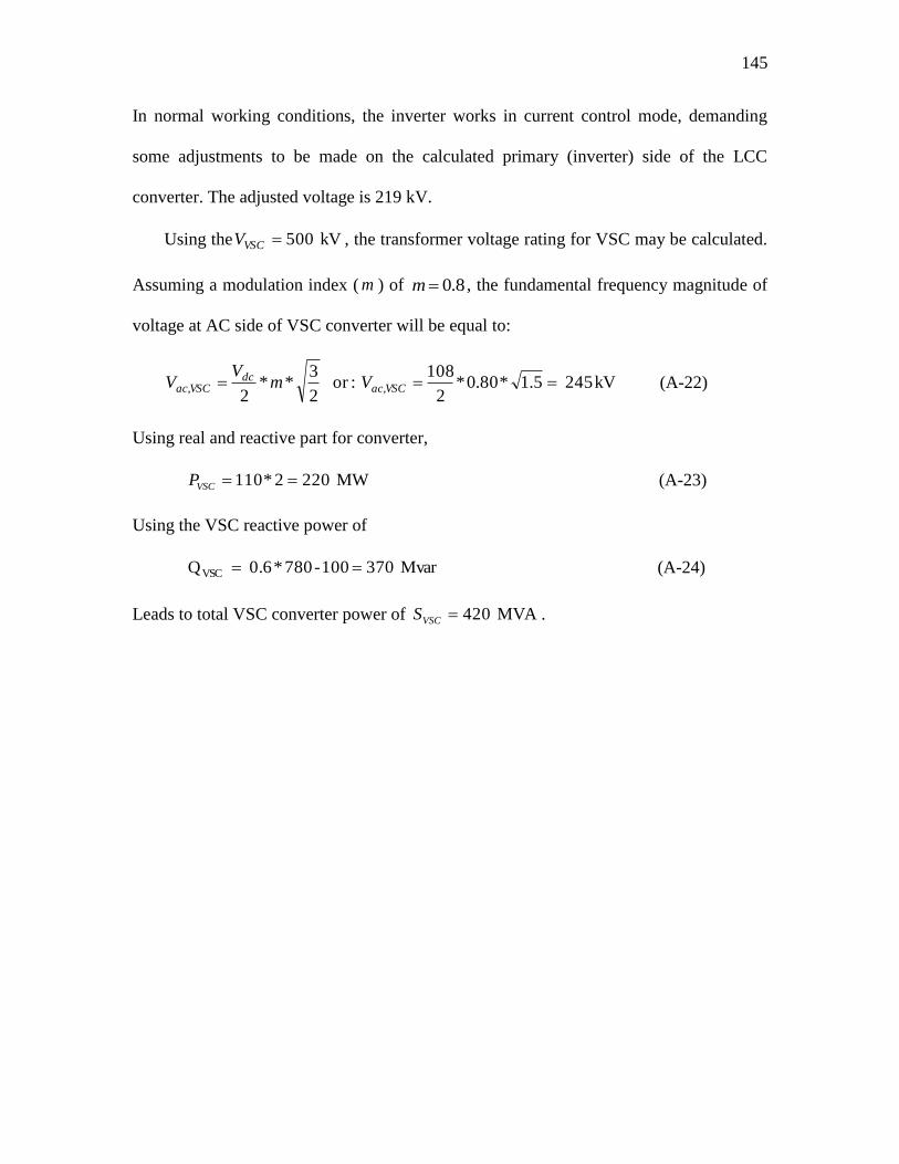
145
In normal working conditions, the inverter works in current control mode, demanding
some adjustments to be made on the calculated primary (inverter) side of the LCC
converter. The adjusted voltage is 219 kV.
Using the kV 500VSCV , the transformer voltage rating for VSC may be calculated.
Assuming a modulation index ( m ) of 8.0m , the fundamental frequency magnitude of
voltage at AC side of VSC converter will be equal to:
kV 245 5.1*80.0*2
108 :or
2
3**
2,, VSCac
dcVSCac Vm
VV (A-22)
Using real and reactive part for converter,
MW 2202*110 VSCP (A-23)
Using the VSC reactive power of
Mvar 370100-780*0.6 QVSC (A-24)
Leads to total VSC converter power of MVA 420VSCS .
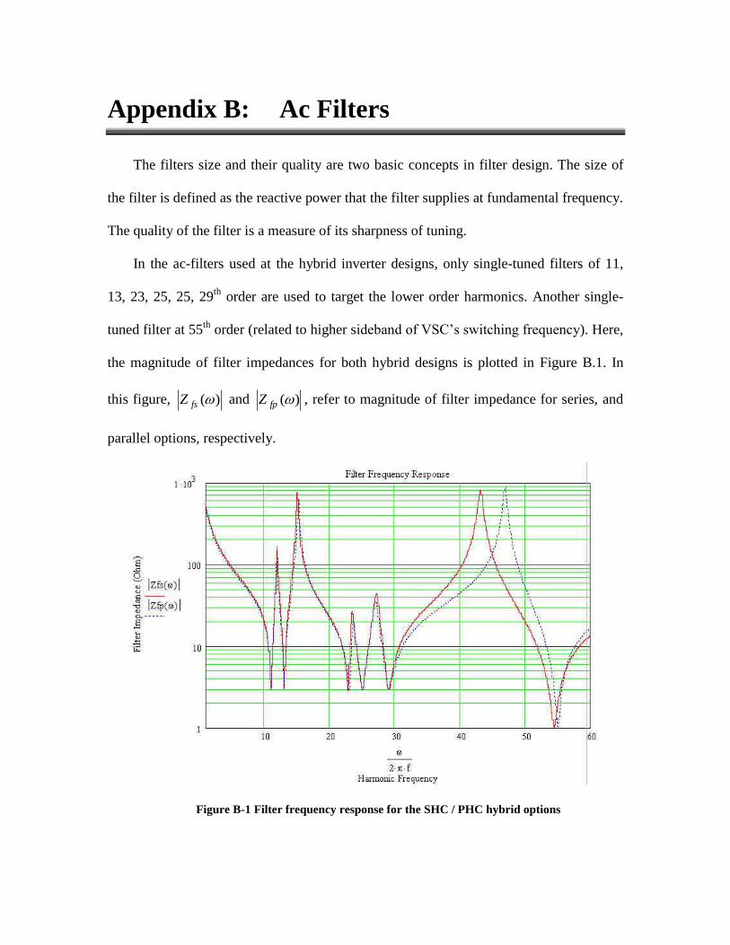
Appendix B: Ac Filters
The filters size and their quality are two basic concepts in filter design. The size of
the filter is defined as the reactive power that the filter supplies at fundamental frequency.
The quality of the filter is a measure of its sharpness of tuning.
In the ac-filters used at the hybrid inverter designs, only single-tuned filters of 11,
13, 23, 25, 25, 29th
order are used to target the lower order harmonics. Another single-
tuned filter at 55th
order (related to higher sideband of VSC‟s switching frequency). Here,
the magnitude of filter impedances for both hybrid designs is plotted in Figure B.1. In
this figure, )(fsZ and )(fpZ , refer to magnitude of filter impedance for series, and
parallel options, respectively.
Figure B-1 Filter frequency response for the SHC / PHC hybrid options

147
In Figure B.2 the normalized frequency response for both designed filters have been
plotted. Here )(
)(
sys
fs
Z
Zand
)(
)(
sys
fp
Z
Z refer to the normalized hybrid option impedances
versus system harmonic frequency.
Figure B-2 Normalized filter frequency response for the SHC/PHC hybrid options
In Table B-1, the filter orders, along with inductor, capacitor and resistor magnitudes
used in simulation cases are tabulated for both of the SHC and PHC options.
In Table B-2, the relative harmonic strength ( iD ) for the individual frequencies,
which have dedicated installed filters, have been given for both of the hybrid options.
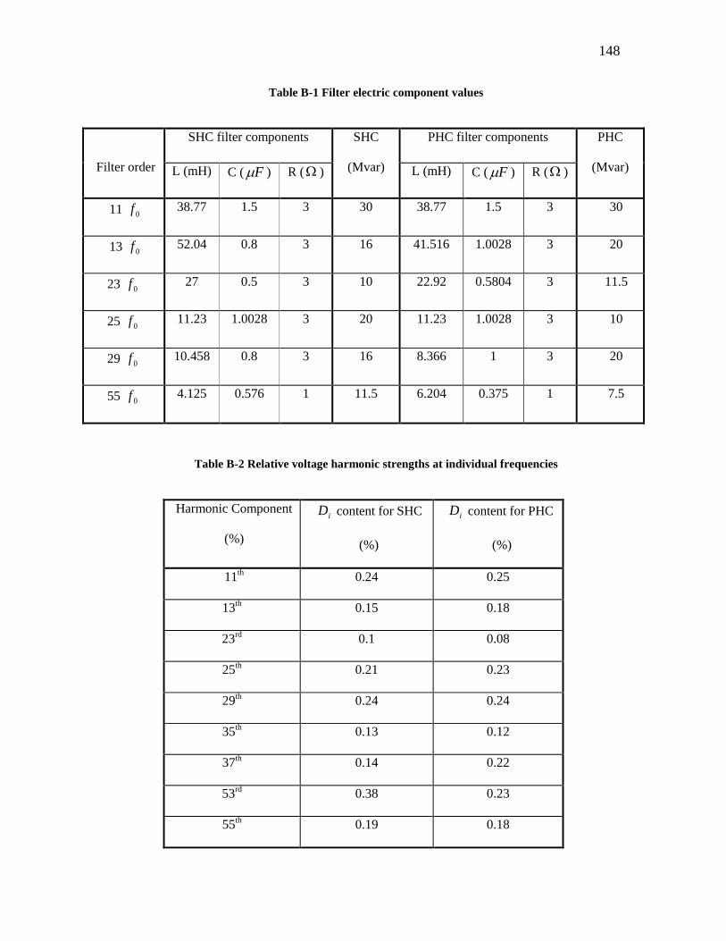
148
Table B-1 Filter electric component values
Filter order
SHC filter components SHC
(Mvar)
PHC filter components PHC
(Mvar) L (mH) C ( F ) R ( ) L (mH) C ( F ) R ( )
11 0f 38.77 1.5 3 30 38.77 1.5 3 30
13 0f 52.04 0.8 3 16 41.516 1.0028 3 20
23 0f 27 0.5 3 10 22.92 0.5804 3 11.5
25 0f 11.23 1.0028 3 20 11.23 1.0028 3 10
29 0f 10.458 0.8 3 16 8.366 1 3 20
55 0f 4.125 0.576 1 11.5 6.204 0.375 1 7.5
Table B-2 Relative voltage harmonic strengths at individual frequencies
Harmonic Component
(%)
iD content for SHC
(%)
iD content for PHC
(%)
11th 0.24 0.25
13th 0.15 0.18
23rd
0.1 0.08
25th 0.21 0.23
29th 0.24 0.24
35th 0.13 0.12
37th 0.14 0.22
53rd
0.38 0.23
55th 0.19 0.18
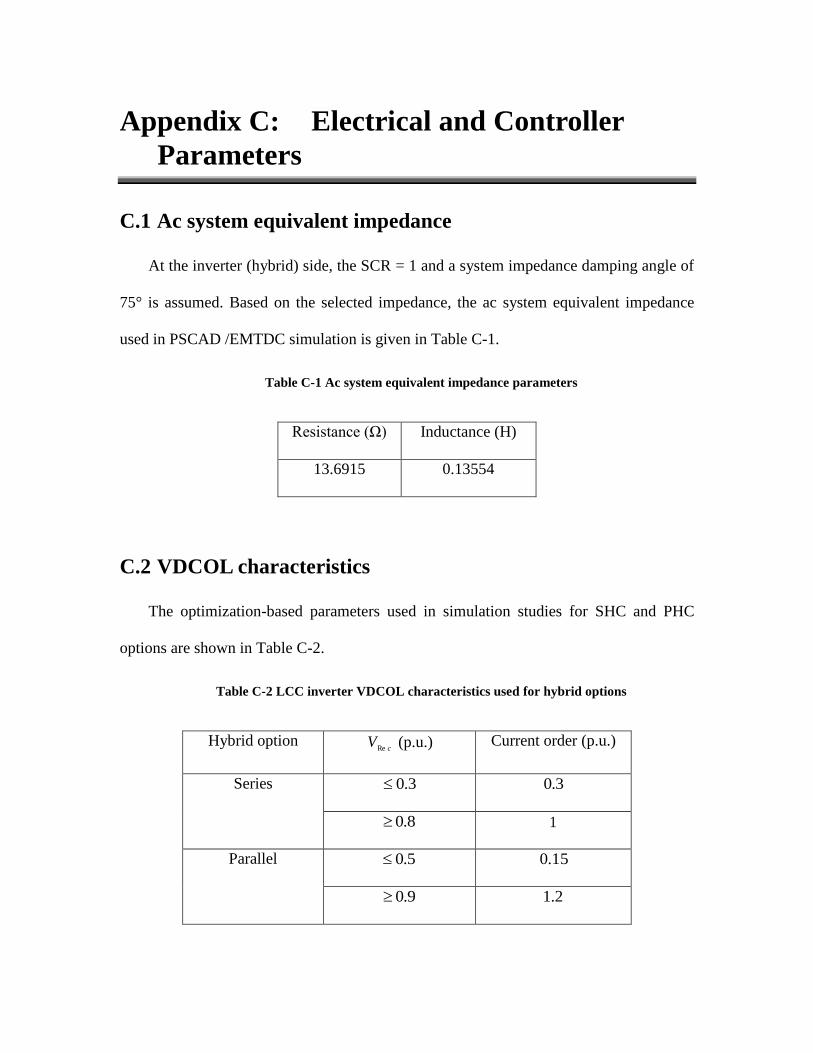
Appendix C: Electrical and Controller
Parameters
C.1 Ac system equivalent impedance
At the inverter (hybrid) side, the SCR = 1 and a system impedance damping angle of
75° is assumed. Based on the selected impedance, the ac system equivalent impedance
used in PSCAD /EMTDC simulation is given in Table C-1.
Table C-1 Ac system equivalent impedance parameters
Resistance (Ω) Inductance (H)
13.6915 0.13554
C.2 VDCOL characteristics
The optimization-based parameters used in simulation studies for SHC and PHC
options are shown in Table C-2.
Table C-2 LCC inverter VDCOL characteristics used for hybrid options
Hybrid option c
VRe
(p.u.) Current order (p.u.)
Series 3.0 3.0
8.0 1
Parallel 5.0 15.0
9.0 2.1
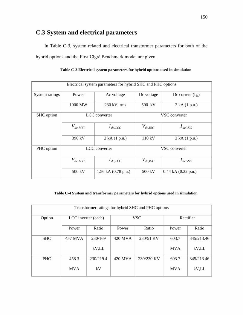
150
C.3 System and electrical parameters
In Table C-3, system-related and electrical transformer parameters for both of the
hybrid options and the First Cigré Benchmark model are given.
Table C-3 Electrical system parameters for hybrid options used in simulation
Electrical system parameters for hybrid SHC and PHC options
System ratings Power Ac voltage Dc voltage Dc current (Idc)
1000 MW 230 kV, rms 500 kV 2 kA (1 p.u.)
SHC option LCC converter VSC converter
LCCdcV , LCCdcI , VSCdcV , VSCdcI ,
390 kV 2 kA (1 p.u.) 110 kV 2 kA (1 p.u.)
PHC option LCC converter VSC converter
LCCdcV , LCCdcI , VSCdcV , VSCdcI ,
500 kV 1.56 kA (0.78 p.u.) 500 kV 0.44 kA (0.22 p.u.)
Table C-4 System and transformer parameters for hybrid options used in simulation
Transformer ratings for hybrid SHC and PHC options
Option LCC inverter (each) VSC Rectifier
Power Ratio Power Ratio Power Ratio
SHC 457 MVA 230/169
kV,LL
420 MVA 230/51 KV 603.7
MVA
345/213.46
kV,LL
PHC 458.3
MVA
230/219.4
kV
420 MVA 230/230 KV 603.7
MVA
345/213.46
kV,LL
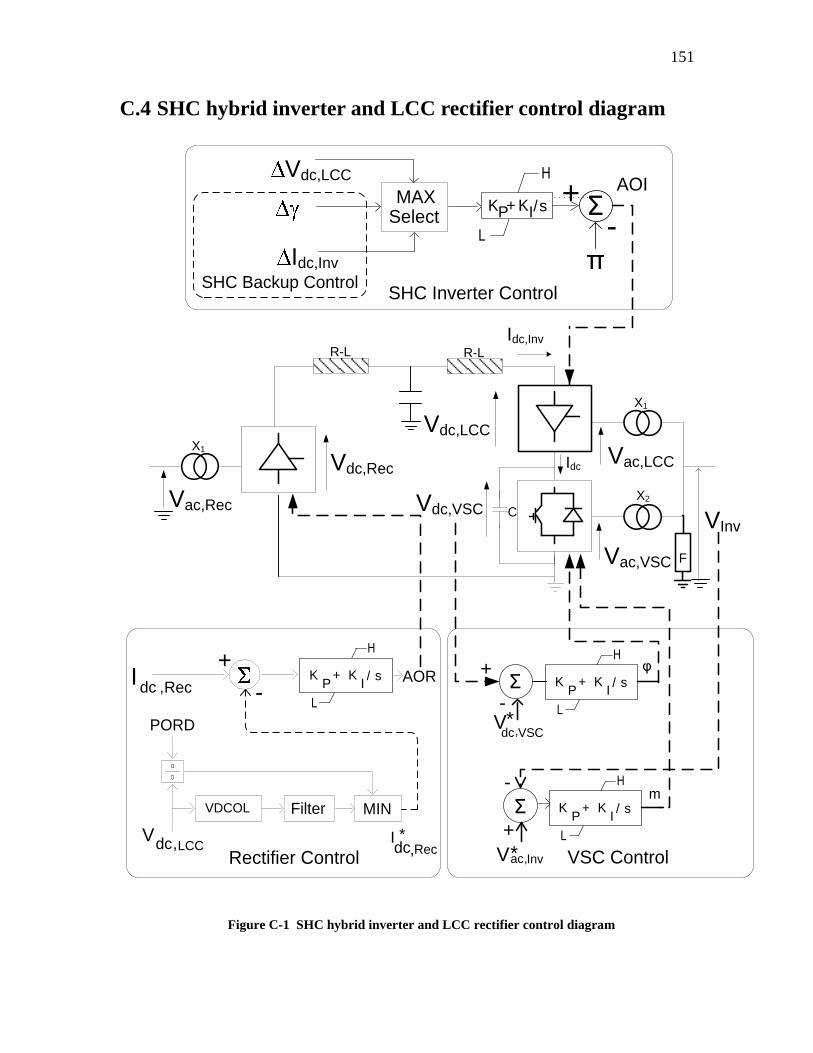
151
C.4 SHC hybrid inverter and LCC rectifier control diagram
VInv
AOR
VDCOL
-
PORD
+
MIN Filter
* Idc,Rec
φ+
-Σ
+
X1
X2
Vac,LCC
Vac,VSC
Vdc,LCC
Vdc,VSC C
Idc
Idc,InvR-L
F
X1
Vac,Rec
Vdc,Rec
Idc ,Rec
Vdc,LCC
H
L
KP
+ KI/ s
R-L
Rectifier Control
MAX Select
AOIVdc,LCC
Idc,Inv
-Σ+
πSHC Inverter Control
H
L
KP+ KI/s
+
-Σ
V*ac,Inv
-m
VSC Control
V*dc,VSC
H
L
KP
+ KI/ s
H
L
KP
+ KI/ s
SHC Backup Control
Figure C-1 SHC hybrid inverter and LCC rectifier control diagram
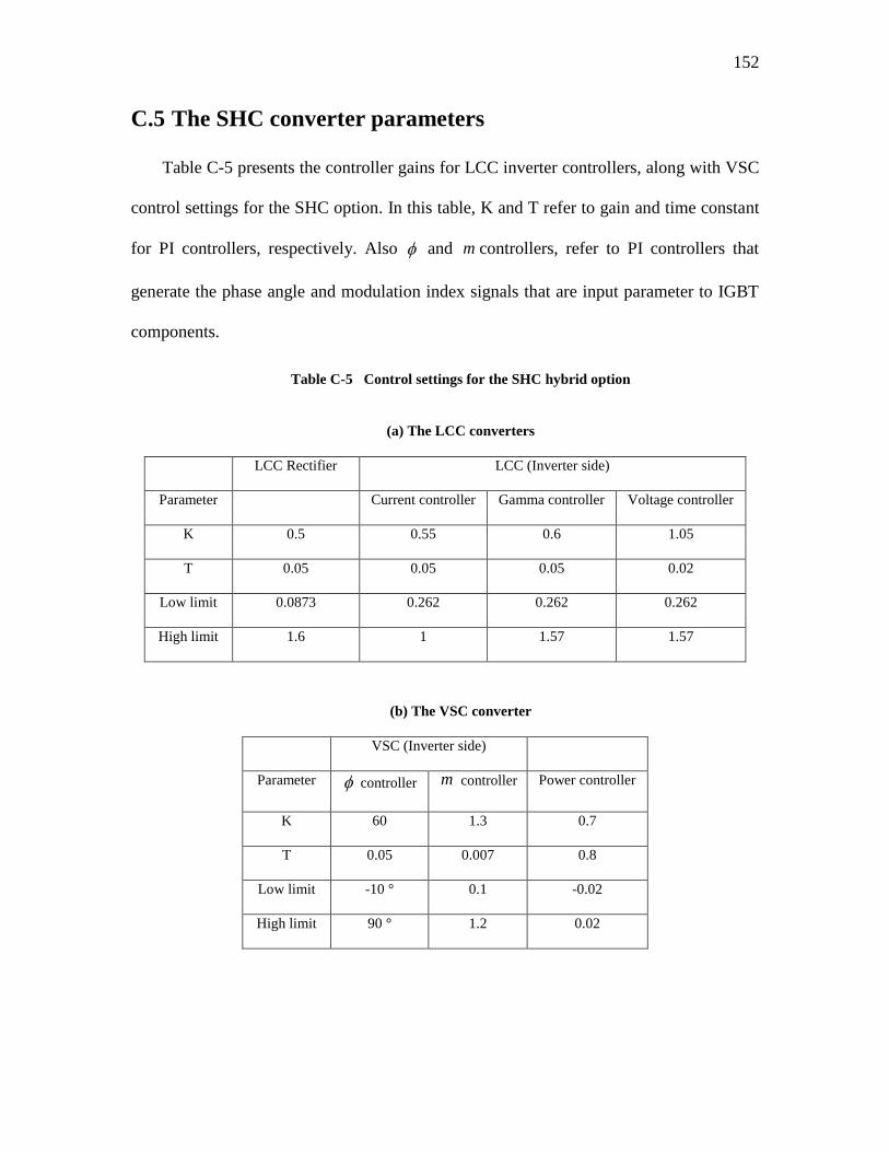
152
C.5 The SHC converter parameters
Table C-5 presents the controller gains for LCC inverter controllers, along with VSC
control settings for the SHC option. In this table, K and T refer to gain and time constant
for PI controllers, respectively. Also and m controllers, refer to PI controllers that
generate the phase angle and modulation index signals that are input parameter to IGBT
components.
Table C-5 Control settings for the SHC hybrid option
(a) The LCC converters
LCC Rectifier LCC (Inverter side)
Parameter Current controller Gamma controller Voltage controller
K 0.5 0.55 0.6 1.05
T 0.05 0.05 0.05 0.02
Low limit 0.0873 0.262 0.262 0.262
High limit 1.6 1 1.57 1.57
(b) The VSC converter
VSC (Inverter side)
Parameter controller m controller Power controller
K 60 1.3 0.7
T 0.05 0.007 0.8
Low limit -10 ° 0.1 -0.02
High limit 90 ° 1.2 0.02
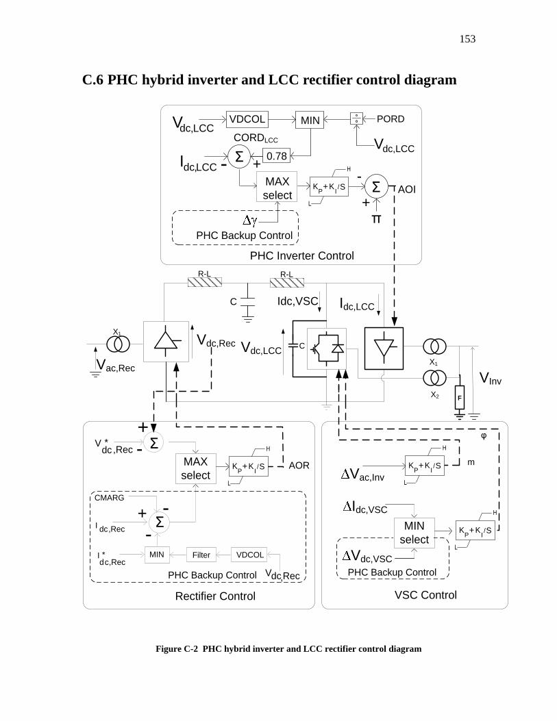
153
C.6 PHC hybrid inverter and LCC rectifier control diagram
VInv
X1
X2
Vdc,LCC
R-L
F
X1
Vac,Rec
Vdc,Rec
R-L
Rectifier Control
PHC Inverter Control
+ -
-
AOR
I dc , Rec
CMARG
MIN
Σ
PHC Backup Control
+
-
Σ
I * dc,Rec
V dc , Rec
VDCOL Filter
V * dc ,Rec
m
PHC Backup Control
φ
C
Idc,LCC
MIN
AOI-
π+
+
Σ
Σ-
PHC Backup Control
Idc,LCC0.78
CORDLCC
Vdc,LCCPORD
Vdc,LCC
H
L
KP+K
I/S
Idc,VSCC
MAX
select
VDCOL
MAX
select
H
L
KP+K
I/S
MIN
select
Vdc,VSC
Idc,VSC
VSC Control
Vac,Inv
H
L
KP+K
I/S
H
L
KP+K
I/S
Figure C-2 PHC hybrid inverter and LCC rectifier control diagram
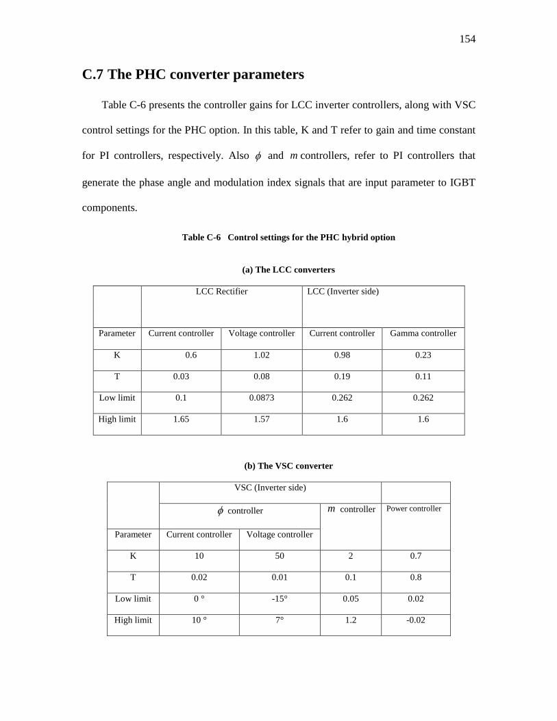
154
C.7 The PHC converter parameters
Table C-6 presents the controller gains for LCC inverter controllers, along with VSC
control settings for the PHC option. In this table, K and T refer to gain and time constant
for PI controllers, respectively. Also and m controllers, refer to PI controllers that
generate the phase angle and modulation index signals that are input parameter to IGBT
components.
Table C-6 Control settings for the PHC hybrid option
(a) The LCC converters
LCC Rectifier LCC (Inverter side)
Parameter Current controller Voltage controller Current controller Gamma controller
K 0.6 1.02 0.98 0.23
T 0.03 0.08 0.19 0.11
Low limit 0.1 0.0873 0.262 0.262
High limit 1.65 1.57 1.6 1.6
(b) The VSC converter
VSC (Inverter side)
controller m controller Power controller
Parameter Current controller Voltage controller
K 10 50 2 0.7
T 0.02 0.01 0.1 0.8
Low limit 0 ° -15° 0.05 0.02
High limit 10 ° 7° 1.2 -0.02
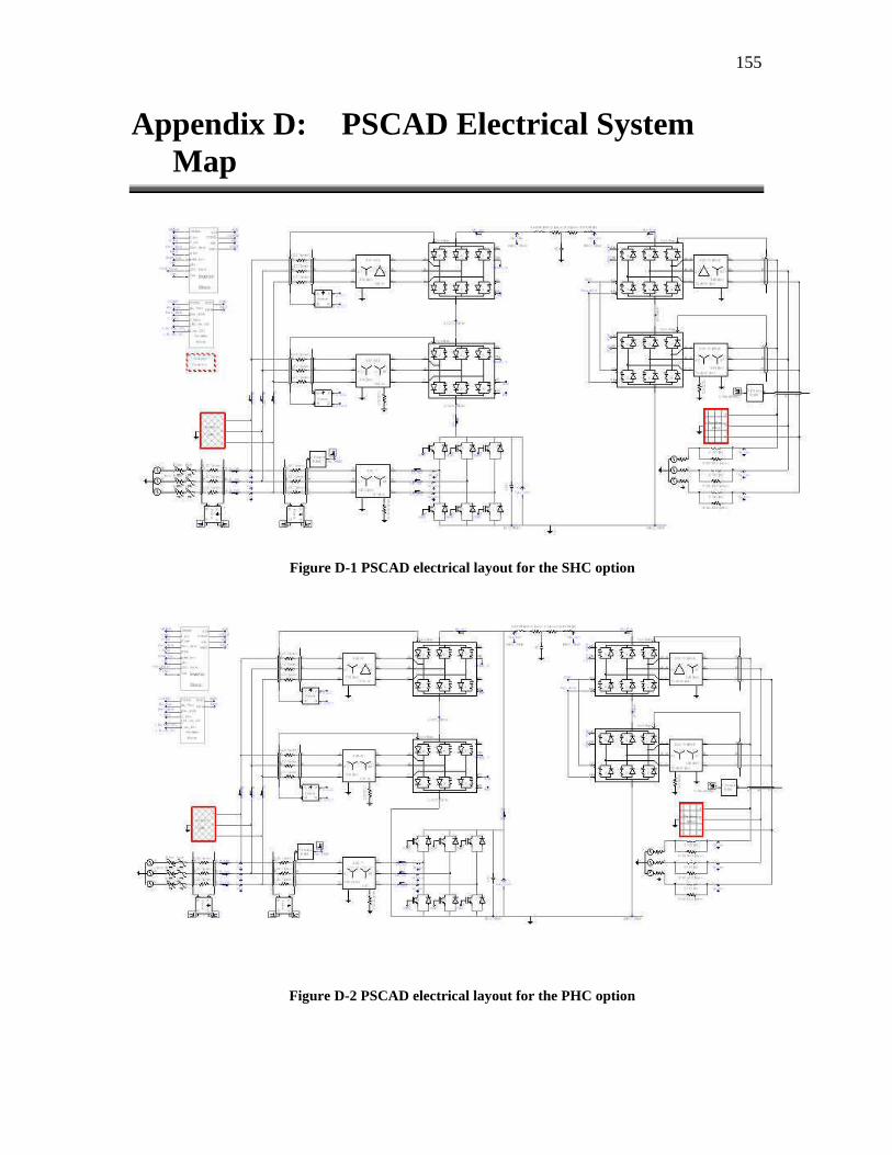
155
Appendix D: PSCAD Electrical System
Map
Figure D-1 PSCAD electrical layout for the SHC option
Figure D-2 PSCAD electrical layout for the PHC option
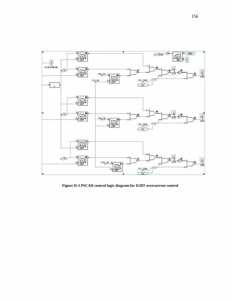
156
Figure D-3 PSCAD control logic diagram for IGBT overcurrent control


![Overview of the Configuration and Power Converters in High ... · Fig. 8. Basic scheme of the LCC-HVDC and VSC-HVDC transmission system [6]. Comparison of the CSC-HVDC and VSC-HVDC](https://img.pdfslide.us/doc/110x75/5ebc0e8dd027f5592e56ad65/overview-of-the-configuration-and-power-converters-in-high-fig-8-basic-scheme.jpg)