Embed Size (px)
Citation preview

MMC10G SeriesLayer 1 Mini Media Converters
MMC10GSP/SP MMC10GT/SP
Installation Guide
613-002801 Rev C
Copyright 2020 Allied Telesis, Inc.All rights reserved. No part of this publication may be reproduced without prior written permission from Allied Telesis, Inc.Allied Telesis and the Allied Telesis logo are trademarks of Allied Telesis, Incorporated. All other product names, company names, logos or other designations mentioned herein are trademarks or registered trademarks of their respective owners.Allied Telesis, Inc. reserves the right to make changes in specifications and other information contained in this document without prior written notice. The information provided herein is subject to change without notice. In no event shall Allied Telesis, Inc. be liable for any incidental, special, indirect, or consequential damages whatsoever, including but not limited to lost profits, arising out of or related to this manual or the information contained herein, even if Allied Telesis, Inc. has been advised of, known, or should have known, the possibility of such damages.

Electrical Safety and Emissions Standards
This section contains the following:
“US Federal Communications Commission”
“Industry Canada”
“Emissions, Immunity and Electrical Safety Standards” on page 4
“Translated Safety Statements” on page 4
US Federal Communications CommissionRadiated Energy
NoteThis equipment has been tested and found to comply with the limits for a Class A digital device pursuant to Part 15 of FCC Rules. These limits are designed to provide reasonable protection against harmful interference when the equipment is operated in a commercial environment. This equipment generates, uses, and can radiate radio frequency energy and, if not installed and used in accordance with this instruction manual, may cause harmful interference to radio communications. Operation of this equipment in a residential area is likely to cause harmful interference in which case the user will be required to correct the interference at his own expense.
NoteModifications or changes not expressly approved of by the manufacturer or the FCC, can void your right to operate this equipment.
Industry CanadaRadiated Energy
This Class A digital apparatus complies with Canadian ICES-003.
Cet appareil numérique de la classe A est conforme à la norme NMB-003 du Canada.
3

Emissions, Immunity and Electrical Safety Standards
RFI Emissions FCC Class A, EN55032 Class A, CISPR 32 Class A, VCCI Class A, RCM
WarningIn a domestic environment this product may cause radio interference in which case the user may be required to take adequate measures. E84
EMC (Immunity) EN55024, EN55035, EN61000-3-2, EN61000-3-3
Electrical Safety EN60950-1 (TUV), UL 60950-1 (CULUS), UL62368-1, EN62368-1, CAN/CSA C22.2 No. 60950-1
WarningLaser Safety: EN60825 L7
Translated Safety Statements
Important: Safety statements that have the symbol are translated into multiple languages in the Translated Safety Statements document at www.alliedtelesis.com/library.
Remarque: Les consignes de sécurité portant le symbole sont traduites dans plusieurs langues dans le document Translated Safety Statements, disponible à l'adresse www.alliedtelesis.com/library.
4
Contents
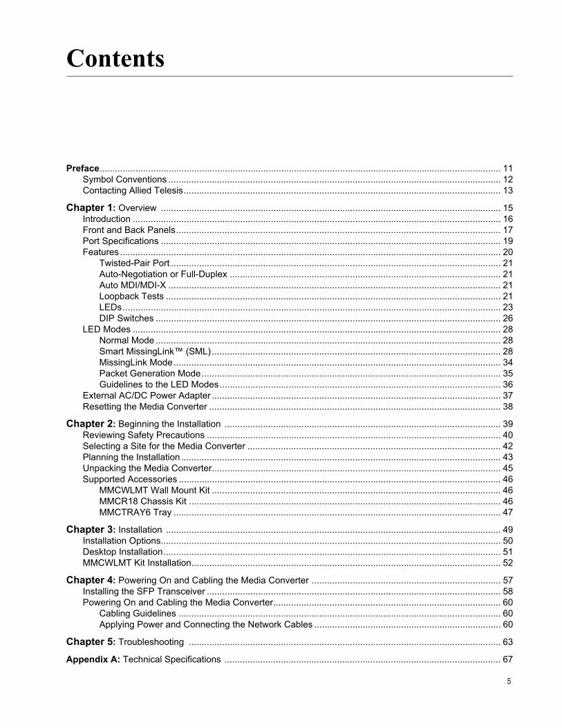
Preface............................................................................................................................................................. 11Symbol Conventions .................................................................................................................................. 12Contacting Allied Telesis............................................................................................................................ 13
Chapter 1: Overview ..................................................................................................................................... 15Introduction ................................................................................................................................................ 16Front and Back Panels............................................................................................................................... 17Port Specifications ..................................................................................................................................... 19Features..................................................................................................................................................... 20
Twisted-Pair Port ................................................................................................................................. 21Auto-Negotiation or Full-Duplex .......................................................................................................... 21Auto MDI/MDI-X .................................................................................................................................. 21Loopback Tests ................................................................................................................................... 21LEDs.................................................................................................................................................... 23DIP Switches ....................................................................................................................................... 26
LED Modes ................................................................................................................................................ 28Normal Mode ....................................................................................................................................... 28Smart MissingLink™ (SML)................................................................................................................. 28MissingLink Mode................................................................................................................................ 34Packet Generation Mode..................................................................................................................... 35Guidelines to the LED Modes.............................................................................................................. 36
External AC/DC Power Adapter ................................................................................................................. 37Resetting the Media Converter .................................................................................................................. 38
Chapter 2: Beginning the Installation ............................................................................................................ 39Reviewing Safety Precautions ................................................................................................................... 40Selecting a Site for the Media Converter ................................................................................................... 42Planning the Installation ............................................................................................................................. 43Unpacking the Media Converter................................................................................................................. 45Supported Accessories .............................................................................................................................. 46
MMCWLMT Wall Mount Kit ................................................................................................................. 46MMCR18 Chassis Kit .......................................................................................................................... 46MMCTRAY6 Tray ................................................................................................................................ 47
Chapter 3: Installation ................................................................................................................................... 49Installation Options..................................................................................................................................... 50Desktop Installation.................................................................................................................................... 51MMCWLMT Kit Installation......................................................................................................................... 52
Chapter 4: Powering On and Cabling the Media Converter .......................................................................... 57Installing the SFP Transceiver ................................................................................................................... 58Powering On and Cabling the Media Converter......................................................................................... 60
Cabling Guidelines .............................................................................................................................. 60Applying Power and Connecting the Network Cables ......................................................................... 60
Chapter 5: Troubleshooting .......................................................................................................................... 63
Appendix A: Technical Specifications ............................................................................................................ 67
5

Contents
Physical Specifications ...............................................................................................................................67Environmental Specifications .....................................................................................................................68Power Specifications ..................................................................................................................................68Safety and Electromagnetic Emissions Certifications ................................................................................68RJ45 Connector and Port Pinouts ..............................................................................................................69
6

Figures
Figure 1: MMC10GT/SP Front Panel................................................................................................................................... 17Figure 2: MMC10GSP/SP Front Panel ................................................................................................................................ 17Figure 3: Media Converter Back Panel................................................................................................................................ 18Figure 4: Alternate Media Converter Back Panel ................................................................................................................ 18Figure 5: Loopback Test for MMC10GT/SP ........................................................................................................................ 22Figure 6: PWR and SYS LEDs on the Back Panel .............................................................................................................. 23Figure 7: Port LEDs on the MMC10GT/SP Media Converter .............................................................................................. 24Figure 8: Port LEDs on the MMC10GSP/SP Model ............................................................................................................ 26Figure 9: Media Converter Back Panel................................................................................................................................ 26Figure 10: Alternate DIP Switch Labels............................................................................................................................... 27Figure 11: SML in Normal Condition with One Media Converter......................................................................................... 29Figure 12: SML in Normal Condition with Two MMC10GT/SP Media Converters............................................................... 29Figure 13: SML in Normal Condition with Two MMC10GSP/SP Media Converters ............................................................ 30Figure 14: SML with Copper Connection Down in One Media Converter Configuration ..................................................... 30Figure 15: SML with Fiber Connection Down in One Media Converter Configuration......................................................... 30Figure 16: SML with Copper Connection Down in Two Media Converters Configuration ................................................... 31Figure 17: SML with Fiber Connection Down in Two Media Converters Configuration....................................................... 31Figure 18: SML with P1 Fiber Connection Down and Link Flapping ................................................................................... 32Figure 19: SML with Fiber Connection Down in Two Media Converters Configuration and No Flapping ........................... 32Figure 20: SML with P2 Fiber Connection Down and Link Flapping ................................................................................... 33Figure 21: SW1 and SW2 DIP Switches.............................................................................................................................. 33Figure 22: ML in Normal Condition with One Media Converter ........................................................................................... 34Figure 23: ML with Fiber Connection Down in One Media Converter Configuration ........................................................... 34Figure 24: ML with Fiber Connection Down in One Media Converter Configuration ........................................................... 34Figure 25: SW1 and SW2 DIP Switch ................................................................................................................................. 35Figure 26: SW1 and SW2 DIP Switch ................................................................................................................................. 35Figure 27: Shipping Package Contents ............................................................................................................................... 45Figure 28: MMCWLMT Kit with Brackets............................................................................................................................. 46Figure 29: MMCR18 Rack-mount Chassis .......................................................................................................................... 47Figure 30: MMCTRAY6 Tray ............................................................................................................................................... 47Figure 31: Attaching the Brackets to the Media Converter .................................................................................................. 53Figure 32: Wall-mount Template ......................................................................................................................................... 53Figure 33: Placing the Template on the Wall....................................................................................................................... 54Figure 34: Securing the Media Converter to the Wall.......................................................................................................... 55Figure 35: Inserting the SFP................................................................................................................................................ 58Figure 36: Positioning the SFP Handle in the Upright Position ........................................................................................... 59Figure 37: Connecting 12VDC Powered Unit ...................................................................................................................... 60Figure 38: MMC10G Series Dimensions ............................................................................................................................. 67Figure 39: RJ45 Connector and Port Pin Layout ................................................................................................................. 69
7

List of Figures
8

Tables
Table 1. Port Specifications for the MMC10GSP/SP ..........................................................................................................19Table 2. Port Specifications for the MMC10GT/SP ............................................................................................................19Table 3. PWR and SYS LEDs on the Back Panel ..............................................................................................................24Table 4. Port LEDs for the MMC10GT/SP ..........................................................................................................................25Table 5. Port LEDs for the MMC10GSP/SP Model ............................................................................................................26Table 6. DIP Switches for the MMC10GT/SP Model ..........................................................................................................27Table 7. Twisted-Pair Port Cabling Specifications ..............................................................................................................43Table 8. MMCWLMT Kit Contents ......................................................................................................................................52Table 9. Physical Specifications .........................................................................................................................................67Table 10. Environmental Specifications ..............................................................................................................................68Table 11. Power Specifications ..........................................................................................................................................68Table 12. Safety and Electromagnetic Emissions Certifications .........................................................................................68Table 13. Pin Signals (1Gbps or 10Gbps) ..........................................................................................................................69
9

List of Tables
10

Preface
This preface contains the following sections:
“Symbol Conventions” on page 12
“Contacting Allied Telesis” on page 13
This guide contains the installation instructions for the following Layer 1 Mini Media Converters.
MMC10GSP/SP
MMC10GT/SP
11

Symbol Conventions
This document uses the following conventions:
NoteNotes provide additional information.
CautionCautions inform you that performing or omitting a specific action may result in equipment damage or loss of data.
WarningWarnings inform you that performing or omitting a specific action may result in bodily injury.
WarningLaser warnings inform you that an eye and skin hazard exists due to the presence of a Class 1 laser device.
12

MMC10G Series Mini Media Converter Installation Guide
Contacting Allied Telesis
If you need assistance with this product, you may contact Allied Telesis technical support by going to the Support & Services section of the Allied Telesis web site at www.alliedtelesis.com/support. You can find links for the following services on this page:
24/7 Online Support - Enter our interactive support center to search for answers to your questions in our knowledge database, check support tickets, learn about Return Merchandise Authorizations (RMAs), and contact Allied Telesis technical experts.
USA and EMEA phone support - Select the phone number that best fits your location and customer type.
Hardware warranty information - Learn about Allied Telesis warranties and register your product online.
Replacement Services - Submit an RMA request via our interactive support center.
Documentation - View the most recent installation guides, user guides, software release notes, white papers and data sheets for your product.
Software Updates - Download the latest software releases for your product.
For sales or corporate contact information, select your region and country, then go to www.alliedtelesis.com/contact.
13

14

Chapter 1
Overview
This chapter contains the following sections:
“Introduction” on page 16
“Front and Back Panels” on page 17
“Port Specifications” on page 19
“Features” on page 20
“LED Modes” on page 28
“External AC/DC Power Adapter” on page 37
“Resetting the Media Converter” on page 38
15

Chapter 1: Overview
Introduction
The MMC10G Series Mini Media Converters extend the distance of your network by interconnecting LAN devices that are physically separated by large distances.
The MMC10G Series Mini Media Converters include the following models:
MMC10GSP/SP
MMC10GT/SP
The MMC10GSP/SP is a fiber mode converter, and can be used for fiber extension.
The MMC10GT/SP is a copper-to-fiber converter, which can be used in Telecom or Enterprise applications where 10 Gigabit media conversion and fiber extension is required.
NoteThe MMC10G Series converters can support 1Gbps and 10Gbps speeds, but as a layer 1 device cannot perform speed translation, so both endpoints must be matched.
16
MMC10G Series Mini Media Converter Installation Guide
17
Front and Back Panels
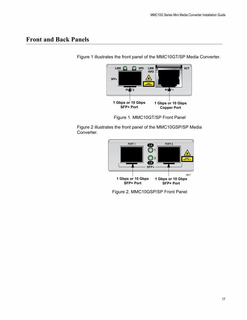
Figure 1 illustrates the front panel of the MMC10GT/SP Media Converter.
Figure 1. MMC10GT/SP Front Panel
Figure 2 illustrates the front panel of the MMC10GSP/SP Media Converter.
Figure 2. MMC10GSP/SP Front Panel
1 Gbps or 10 GbpsSFP+ Port
1 Gbps or 10 GbpsCopper Port
1 Gbps or 10 GbpsSFP+ Port
1 Gbps or 10 GbpsSFP+ Port

Chapter 1: Overview
Figure 3 illustrates the back panel of the MMC10G Series Media Converter.
Figure 3. Media Converter Back Panel
NoteAlternately, the back panel may be labeled differently as shown in Figure 4. The DIP switches have the same ON/OFF function as described in Table 6 on page 23.
Figure 4. Alternate Media Converter Back Panel
12V Input
SYS LED
PWR LED
SW1 ON/OFFDIP Switch
SW2 ON/OFFDIP Switch
12VDC Input
SYS LED
PWR LED
SML ON/OFFDIP Switch
LPBK ON/OFF
DIP Switch
18

MMC10G Series Mini Media Converter Installation Guide
Port Specifications
The MMC10GSP/SP Media Converter allows enterprises to connect fiber networks to fiber networks, offering a cost-effective method for integrating fiber-optic cabling into 1Gbps SFP or 10Gbps SFP+. See Table 1 for the port specifications of the MMC10GSP/SP Media Converter.
The MMC10GT/SP Media Converter allows enterprises to connect copper networks to fiber networks, offering a cost-effective method for integrating fiber optic cabling into an unshielded twisted pair (UTP) environment. See Table 2 for the port specifications of the MMC10GT/SP Media Converter.
Table 1. Port Specifications for the MMC10GSP/SP
ModelFiber-optic Port 1 Fiber-optic Port 2
Connector L1 Standard Connector L1 Standard
MMC10GSP/SP SFP+ 1000BASE-X/10GBASE-R
SFP+ 1000BASE-X/10GBASE-R
Table 2. Port Specifications for the MMC10GT/SP
ModelFiber-optic Port Copper Port
Connector L1 Standard Connector L1 Standard
MMC10GT/SP SFP+ 1000BASE-X/10GBASE-R
RJ-451000BASE-T/10GBASE-T
19

Chapter 1: Overview
Features
Here are the key features of the MMC10G Series Media Converters:
10G copper cabling up to 100m with CAT6A
MMC10GSP/SP supports two SFP+ ports
MMC10GT/SP supports one SFP+ port and one copper RJ45 port
MMC10GSP/SP can operate with any combination of supported multi-mode modules, single-mode modules, or direct attach cables
MMC10GT/SP can convert between 10GBASE-T and any of the supported multi-mode modules, single-mode modules, or direct attach cables
Supports 100% traffic throughput and has no packet restrictions
Supports built-in loopback mode for installation verification and troubleshooting
MMC10GT/SP supports packet generation mode for troubleshooting
Facilitates quick fault detection, isolation and reporting with Smart MissingLink™ (SML)
Includes a DIP switch for activating the SML feature
Includes a DIP switch for Loopback mode
Utilizes a 12 VDC external wall-mount AC power adapter
Displays LEDs for immediate visual status of each port
Provides a smaller sized space-saving alternative to connected networks
Includes installation options such as desktop, media converter chassis, or wall mount bracket
Provides low latency (~50ns)
Supports 1G to 1G or 10G to 10G modes
Auto-detects SFP+ speed
Complies with RoHS requirements
Complies with Trade Act Agreement (TAA) requirements
Applies Auto Negotiation and Auto MDI/MDI-X on the twisted-pair port
NoteThe SFP+ transceivers are sold separately. The maximum operating distance of the MMC10G Series is dependent on the specific SFP+ module. For a list of supported transceivers, refer to the product’s data sheet.
20

MMC10G Series Mini Media Converter Installation Guide
Twisted-Pair Port Here are the basic features of the twisted-pair (copper) port on the MMC10GT/SP:
1Gbps or 10Gbps
IEEE 802.3u Auto-Negotiation compliant
Auto MDI/MDI-X
100 meters (328 feet) maximum operating distance
RJ45 connector
The twisted-pair port features an eight-pin RJ45 connector that uses all eight pins at 1Gbps or 10Gbps. For the port pinouts, see “RJ45 Connector and Port Pinouts” on page 69.
NoteFor twisted-pair port cabling specifications, refer to “Cabling Guidelines” on page 60.
Auto-Negotiationor Full-Duplex
The MMC10GT/SP Media Converter supports Auto-Negotiation at 1Gbps or 10Gbps. The copper port will only link at the speed of the installed SFP+ module. For example, if a 10G SFP+ module is installed, the copper port can only link at 10G.
Auto MDI/MDI-X
The 10Gbps RJ45 twisted-pair port on MMC10GT/SP can have one of two possible wiring configurations: MDI or MDI-X.
The media converter features Auto MDI/MDI-X. The twisted-pair port automatically determines the configuration of the port on the device to which it is connected and then configures itself appropriately.
This feature allows you to use a straight-through cable when connecting any type of device to the media converter, regardless of the wiring configuration of the port on the device.
Loopback Tests Loopback tests are used to test the fiber optic network connection. In loopback mode, the copper port is disabled and the fiber port is set to loop all packets back to the sender, or generate packets, depending on the DIP switch setting. A linked switch port can transmit test packets over the fiber optic cable, which are then looped back by the connected MMC10G. As it receives its original test packets, it checks for lost packets and packets with errors, and displays the results in statistic counters. Figure 5 on page 22 shows a successful test, using an Allied Telesis switch as the link partner.
21

Chapter 1: Overview
Figure 5. Loopback Test for MMC10GT/SP
A successful test verifies that the number of packets received equals the number of packets sent. If the numbers do not match, try restarting the media converter, making sure that the cables are connected properly or replacing the fiber cable.
22

MMC10G Series Mini Media Converter Installation Guide
NoteLoopback tests only work for fiber optic ports, you cannot test a copper port. Additionally, the fiber cable connectivity can only be tested using the SFP+ 10Gbps transmitter. It cannot be tested with SFP 1Gbps transmitter.
NoteTwo SFP+ modules must be installed prior to enabling Loopback Mode, or loopback will not function properly.
To use Loopback Mode, set SW1 to OFF and SW2 to ON. For more information about DIP switches and how to set them, refer to “DIP Switches” on page 26.
Caution
Loopback tests are disruptive to network operations. The media converters do not forward network traffic during the test. Some network traffic may be lost.
LEDs MMC10GT/SP and MMC10GSP/SP Back Panel
Figure 6 shows the PWR and SYS LEDs on the back panel.
Figure 6. PWR and SYS LEDs on the Back Panel
PWR
SYS
23

Chapter 1: Overview
Table 3 describes the media converter LEDs on the back panel.
MMC10GT/SP Front Panel
Figure 7 shows the port LEDs on the front panel of the MMC10GT/SP Media Converter.
Figure 7. Port LEDs on the MMC10GT/SP Media Converter
Table 3. PWR and SYS LEDs on the Back Panel
LED State Description
PWROff The media converter is not receiving power.
Steady Green The media converter is receiving power.
SYS
Off The media converter is not operational and will not forward traffic.
Steady Green The media converter is operational in normal mode.
Medium Flashing Green
The media converter is in Loopback mode.
Slow Flashing Green
An error is present on the media converter. Or, an SFP in not valid.
LINK SPEED
ACTIVITYSPEEDLINK/
24

MMC10G Series Mini Media Converter Installation Guide
Table 4 describes the port LEDs on the front panel of the MMC10GT/SP Media Converter.
Table 4. Port LEDs for the MMC10GT/SP
LED State Description
Port 1Copper
Link/Speed(Left)
Off The port has not established a link.
Steady Green The port has a 10G link to a network device.
Steady Amber The port has a 1G link to a network device.
Slow Flashing Green
The media converter is operating in Smart MissingLink mode and the SFP+ port has lost link.
Port 1CopperActivity(Right)
Off The port has not established a link.
Steady Green The copper port has an established a link.
Flashing Green
There is network activity through the media converter
Slow Flashing Green
The media converter is operating in Smart MissingLink mode and the SFP+ port has lost link.
Port 2 Fiber Optic
Link(Left)
Off The port is empty or the transceiver has not established a link.
Steady Green The port has a link to a network device.
Slow Flashing Green
The media converter is operating in Smart MissingLink mode and the copper port has lost link.
Port 2 Fiber Optic
Speed(Right)
Steady Green The media converter has detected an installed 10G SFP+ module and is operating at 10Gbps.
Steady Amber The media converter has detected an installed 10G SFP+ module and is operating at 10Gbps.
Off The port is empty or the transceiver has not established a link.
Alternating Flashing
Amber and Green
The port is empty and does not have a transceiver inserted. Or, the installed transceiver is invalid.
25

Chapter 1: Overview
MMC10GSP/SP Front Panel
Figure 8 shows the port LEDs on the MMC10GSP/SP Media Converter.
Figure 8. Port LEDs on the MMC10GSP/SP Model
Table 5 describes the port LEDs on the MMC10GSP/SP model.
DIP Switches The DIP switches enable/disable SML and Loopback Modes. Refer to Figure 9.
Figure 9. Media Converter Back Panel
Link/Activity 1
Link/Activity 2
Table 5. Port LEDs for the MMC10GSP/SP Model
LED State Description
Ports 1 and 2
Link/Activity
Off The port has not established a link.
Steady Green The port has established a link to a network device.
Slow Flashing Green
The media converter is operating in Smart Missing Link mode, and the other port has lost link.
SW1 ON/OFFDIP Switch
SW2 ON/OFFDIP Switch
26

MMC10G Series Mini Media Converter Installation Guide
NoteAlternately, the back panel may be labeled differently as shown in Figure 10. The DIP switches have the same ON/OFF function as described in Table 6.
Figure 10. Alternate DIP Switch Labels
Table 6 describes the functions of the DIP switches.
Table 6. DIP Switches for the MMC10GT/SP Model
SW1/SML SW2/LPBK Description
Off/Down Off/Down Normal operation (no missing link)
On/Up Off/Down Smart MissingLink mode enabled
Off/Down On/Up Loopback mode enabled
On/Up On/Up MMC10GT/SP only: Packet generation enabledMMC10GSP/SP only: MissingLink mode enabled
SW1/SML ON/OFF DIP Switch
SW2/LPBK ON/OFFDIP Switch
27

Chapter 1: Overview
LED Modes
The ports have LEDs that display link status and traffic activity. The LEDs have three modes:
Regular mode
Smart MissingLink mode
MissingLink mode
Normal Mode The Link/Activity LEDs on the media converter DIP switch set to the normal mode (i.e., SML and Loopback Mode are not switched on) display the status of the links on the ports to network devices. For instance, the LEDs are solid green when ports have established links to network devices, or flashing green when they are actively transmitting or receiving network traffic. Conversely, the LEDs are off on ports that are not connected to network devices or have not established links to devices.
The normal mode is typically used when the network devices connected to a media converter cannot take advantage of the Smart MissingLink mode, or when you want to use the Link LEDs to troubleshoot a link problem. This mode is also useful after you have installed the media converter modules and want to verify whether the ports have successfully established links with the local and remote network devices.
SmartMissingLink™
(SML)
If one of the Ethernet connections to the media converter loses a link, the SML feature allows you to determine which port still has a valid connection and which port requires troubleshooting. The value to this type of network monitoring and fault notification is that you can quickly determine which media converter port has failed and troubleshoot the specific area where the problem is occurring.
NoteSML only works with 10G connections.
When the media converter detects a loss of connection on one of the ports, the port’s Link LED is turned OFF. At the same time, the media converter causes the opposite port’s Link LED to blink while simultaneously turning OFF that port’s Ethernet connection to its end node. This occurs even though the properly operating port had a valid connection before the failure occurred. The reason for this is so that its end node is notified that the data path has been compromised, and immediate action is required.
For example, if the network connection to the MMC10GT/SP Media Converter’s twisted-pair port fails (as shown in Figure 14 on page 30), the fiber Port 2 Link LED blinks slowly while the fiber port’s link is turned OFF.
28

MMC10G Series Mini Media Converter Installation Guide
The copper Port 1 Link LED is turned OFF, indicating a failed connection on the twisted-pair port.
If the failure had started with the fiber-optic cabling (as shown in Figure 15 on page 30), then the copper Port 1 Link LED would blink slowly, and the fiber Port 2 Link LED would turn OFF.
SML Example Scenarios in Normal Condition
Following are example scenarios with SML-enabled media converters.
Figure 11 shows Link LED behavior of end nodes and a media converter with copper and fiber ports with SML enabled under normal condition.
Figure 11. SML in Normal Condition with One Media Converter
Figure 12 shows Link LED behavior of end nodes and MMC10GT/SP media converters with SML enabled under normal condition. Two media converters with copper and fiber ports are connected in this configuration.
Figure 12. SML in Normal Condition with Two MMC10GT/SP Media Converters
Figure 13 shows Link LED behavior of end nodes and MMC10GSP/SP media converters with SML enabled under normal condition. Two media converters with fiber ports are connected in this configuration.
NoteFor SML to function properly in a back-to-back scenario, Port 2 must be used to connect the two media converters together.
MMC10GT/SP
Copper Link Fiber Link
End Node Copper Cable Fiber Cable
Link LED On
End Node
Link LED OnLED On LED On
Port 1 Port 2
MMC10GT/SP
Fiber Cable
End Node
Link LED On
End Node
Link LED On
MMC10GT/SP
Copper Link Fiber LinkLED On LED On
Fiber LinkLED On
Copper LinkLED On
Copper Cable Copper Cable
Port 1 Port 2 Port 2 Port 1
29

Chapter 1: Overview
Figure 13. SML in Normal Condition with Two MMC10GSP/SP Media Converters
SML Example Scenarios with Connection Down in One Media Converter Configuration
Figure 14 shows the MMC10GT/SP media converter and end node Link LED behavior with SML enabled with a copper connection down.
Figure 14. SML with Copper Connection Down in One Media Converter Configuration
Figure 15 shows the MMC10GT/SP media converter and end node Link LED behavior with SML enabled with a fiber connection down.
Figure 15. SML with Fiber Connection Down in One Media Converter Configuration
MMC10GSP/SPEnd Node
Link LED On
End Node
Link LED On
MMC10GSP/SP
Fiber Link Fiber LinkLED On LED On
Fiber LinkLED On
Fiber LinkLED On
Fiber Cable
Fiber CableFiber Cable
Port 1 Port 2 Port 1 Port 2
MMC10GT/SP
Copper Link Fiber Link
End Node Copper Cable Fiber Cable
Link LED Off
End Node
Link LED BlinkingLED Off LED Blinking
Port 1 Port2
MMC10GT/SP
Copper Link Fiber Link
End Node Copper Cable Fiber Cable
Link LED Off
End Node
Link LED Off
LED Blinking LED Off
Port 1 Port 2
30

MMC10G Series Mini Media Converter Installation Guide
SML Example Scenarios with Connection Down in Two Media Converters Configuration
Following are example scenarios with two SML enabled media converters connected back-to-back (bookend mode).
Figure 16 shows the MMC10GT/SP media converter and end node Link LED behavior with SML enabled with a copper connection down between a media converter and an end node.
Figure 16. SML with Copper Connection Down in Two Media Converters Configuration
Figure 17 shows the MMC10GT/SP media converter and end node Link LED behavior with SML enabled with a fiber connection down between two media converters.
Figure 17. SML with Fiber Connection Down in Two Media Converters Configuration
MMC10GT/SPEnd Node
Link LED Off
End Node
Link LED Off
MMC10GT/SP
Copper Link Fiber LinkLED Off LED Blinking
Fiber LinkLED Blinking
Copper LinkLED Blinking
Fiber CableCopper Cable Copper Cable
Port 1 Port 2 Port 1 Port 2
MMC10GT/SPEnd Node
Link LED Off
End Node
Link LED Off
MMC10GT/SP
Copper Link Fiber LinkLED Blinking LED Off
Fiber LinkLED Off
Copper LinkLED Blinking
Fiber CableCopper Cable Copper Cable
Port 1 Port 2 Port 1 Port 2
31

Chapter 1: Overview
SML Example Scenarios with Connection Down in Two Media Converter Configuration
Figure 18 shows MMC10GSP/SP media converter and end node Link LED behavior with SML enabled with a P1 fiber connection down between a media converter and an end node. This forces the P2 link down and flaps the P2 link status.
Figure 18. SML with P1 Fiber Connection Down and Link Flapping
Figure 19 shows MMC10GSP/SP media converter when P2 detects a link down or flapping, it behaves the same as ML Mode which forces P1 link down and blinks P1 LED, but does NOT flap the P1 status.
Figure 19. SML with Fiber Connection Down in Two Media Converters Configuration and No Flapping
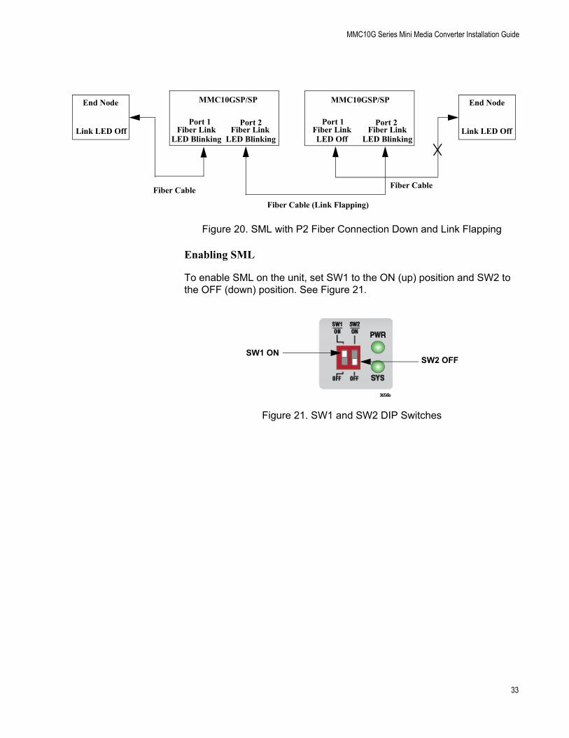
Figure 20 on page 33 shows MMC10GSP/SP media converter and end node Link LED behavior with SML enabled with a P1 fiber connection down between a media converter and an end node. This forces the P2 link down and flaps the P2 link status.
MMC10GSP/SPEnd Node
Link LED Off
End Node
Link LED Off
MMC10GSP/SP
Fiber Link Fiber LinkLED Off LED Blinking
Fiber LinkLED Blinking
Fiber LinkLED Blinking
Fiber Cable (Link Flapping)
Fiber CableFiber Cable
Port 1 Port 2 Port 1 Port 2
MMC10GSP/SPEnd Node
Link LED Off
End Node
Link LED Off
MMC10GSP/SP
Fiber Link Fiber LinkLED Blinking LED Off
Fiber LinkLED Blinking
Fiber LinkLED Off
Fiber Cable
Fiber CableFiber Cable
Port 1 Port 2 Port 1 Port 2
32
MMC10G Series Mini Media Converter Installation Guide
Figure 20. SML with P2 Fiber Connection Down and Link Flapping
Enabling SML
To enable SML on the unit, set SW1 to the ON (up) position and SW2 to the OFF (down) position. See Figure 21.
Figure 21. SW1 and SW2 DIP Switches
MMC10GSP/SPEnd Node
Link LED Off
End Node
Link LED Off
MMC10GSP/SP
Fiber Link Fiber LinkLED Blinking LED Blinking
Fiber LinkLED Off
Fiber LinkLED Blinking
Fiber Cable (Link Flapping)
Fiber CableFiber Cable
Port 1 Port 2 Port 1 Port 2
SW2 OFFSW1 ON
33

Chapter 1: Overview
MissingLinkMode
ML Example Scenarios in Normal Condition
NoteThe MissingLink Mode applies to the MMC10GSP/SP Media Converter only.
Following are example scenarios with ML-enabled media converters.
Figure 22 shows Link LED behavior of end nodes and a media converter with fiber ports with ML enabled under normal condition.
Figure 22. ML in Normal Condition with One Media Converter
ML Example Scenarios with Connection Down in One Media Converter Configuration
Figure 23 shows a media converter and end node Link LED behavior with ML enabled with a fiber connection down.
Figure 23. ML with Fiber Connection Down in One Media Converter Configuration
Figure 24 shows media converter and end node Link LED behavior with SML enabled with a fiber connection down.
Figure 24. ML with Fiber Connection Down in One Media Converter Configuration
MMC10GSP/SP
Fiber Link Fiber Link
End Node Fiber Cable Fiber Cable
Link LED On
End Node
Link LED OnLED On LED On
Port 1 Port 2
MMC10GSP/SP
FiberLink Fiber Link
End Node Fiber Cable Fiber Cable
Link LED Off
End Node
Link LED OffLED Off LED Blinking
Port 1 Port 2
MMC10GSP/SP
Fiber Link Fiber Link
End Node Fiber Cable Fiber Cable
Link LED Off
End Node
Link LED Off
LED Blinking LED Off
Port 1 Port 2
34
MMC10G Series Mini Media Converter Installation Guide
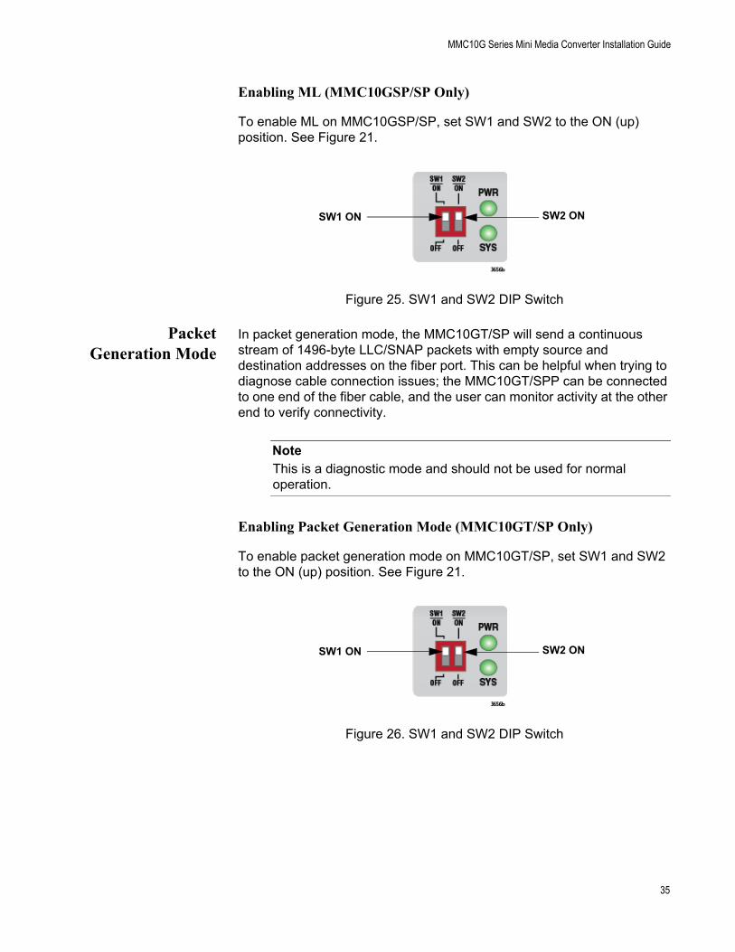
Enabling ML (MMC10GSP/SP Only)
To enable ML on MMC10GSP/SP, set SW1 and SW2 to the ON (up) position. See Figure 21.
Figure 25. SW1 and SW2 DIP Switch
PacketGeneration Mode
In packet generation mode, the MMC10GT/SP will send a continuous stream of 1496-byte LLC/SNAP packets with empty source and destination addresses on the fiber port. This can be helpful when trying to diagnose cable connection issues; the MMC10GT/SPP can be connected to one end of the fiber cable, and the user can monitor activity at the other end to verify connectivity.
NoteThis is a diagnostic mode and should not be used for normal operation.
Enabling Packet Generation Mode (MMC10GT/SP Only)
To enable packet generation mode on MMC10GT/SP, set SW1 and SW2 to the ON (up) position. See Figure 21.
Figure 26. SW1 and SW2 DIP Switch
SW2 ONSW1 ON
SW2 ONSW1 ON
35

Chapter 1: Overview
Guidelines to theLED Modes
Here are the guidelines to using the LED modes:
Smart MissingLink mode is the default for MMC10GT/SP.
MissingLink mode is the default for MMC10GSP/SP.
The LED modes do not block or interfere with the flow of traffic between the two ports during normal network operations.
Smart MissingLink and Regular modes are useful in identifying ports that cannot establish links to network devices or have lost links. In Smart MissingLink mode, if only one port has a link to a network device, the LED for the port that lost link will be off, while the LED for the port that had a valid link will blink once a second. In contrast, if the media converter is set to Regular mode, and only one port has a link to a network device, its Link LED will be on while the Link LED on the port with no link will be off.
NoteThe MMC10GT/SP cannot link in 1G mode unless both ports have valid link partners
The Smart MissingLink mode can also be useful in situations where both network devices connected to the ports can react to the loss of a link by performing specific actions, such as sending SNMP traps or seeking a redundant path.
36

MMC10G Series Mini Media Converter Installation Guide
External AC/DC Power Adapter
The media converter comes with a UL-approved safety compliant AC power adapter for 120 and 240 VAC environments, with a regulated output of 12 VDC. The power required for the media converter is 12 VDC, 350 mA.
The power adapter comes with four plugs. Install the correct plug for your region on the power adapter. Refer to “Unpacking the Media Converter” on page 45 and “Applying Power and Connecting the Network Cables” on page 60.
NoteThe media converter power receptacle has a twist-and-lock barrel which is locked by turning the power cord clockwise one-quarter turn.
37

Chapter 1: Overview
Resetting the Media Converter
You may have to power cycle the media converter when entering or exiting loopback or packet generation mode. If so, reset the media converter by powering OFF then powering ON the unit.
38

Chapter 2
Beginning the Installation
This chapter contains the following sections:
“Reviewing Safety Precautions” on page 40
“Selecting a Site for the Media Converter” on page 42
“Planning the Installation” on page 43
“Unpacking the Media Converter” on page 45
“Supported Accessories” on page 46
39

Chapter 2: Beginning the Installation
Reviewing Safety Precautions
Important: Safety statements that have the symbol are translated into multiple languages in the Translated Safety Statements document at www.alliedtelesis.com/library.
Remarque: Les consignes de sécurité portant le symbole sont traduites dans plusieurs langues dans le document Translated Safety Statements, disponible à l'adresse www.alliedtelesis.com/library.
Review the following safety precautions before you begin to install the chassis or any of its components.
NoteThe indicates that a translation of the safety statement is available in a PDF document titled Translated Safety Statements on the Allied Telesis website at www.alliedtelesis.com/support.
Caution
Air vents must not be blocked and must have free access to the room ambient air for cooling. E6
NoteAll Countries: Install product in accordance with local and National Electrical Codes. E8
NoteThe power input must be provided from SELV source only, per IEC60950. Do not connect to a centralized DC battery bank. E31
Warning
Operating Temperature. MMC10GT/SP is designed for a maximum ambient temperature of 40° C and the MMC10GSP/SP for 50° C. E138
40

MMC10G Series Mini Media Converter Installation Guide
Caution
Failing to pick up the ferrule tip when you reach the bottom of the cleaning surface can result in static electricity that can damage the fiber-optic cable. E82
Warning
In a domestic environment this product may cause radio interference in which case the user may be required to take adequate measures. E84
Warning
An SFP+ transceiver can be damaged by static electricity. Be sure to observe all standard electrostatic discharge (ESD) precautions, such as wearing an antistatic wrist strap, to avoid damaging the transceiver. E86
Caution
Only use the power adapter supplied with the device. E102
Warning
Do not stare into the laser beam. L2
Warning
Do not look directly at the fiber-optic cable ends or inspect the cable ends with an optical lens. L6
Warning
Laser Safety: EN60825-1. L7
41

Chapter 2: Beginning the Installation
Selecting a Site for the Media Converter
Observe the following requirements when choosing a site for your media converter:
If you are installing the media converter on a table, verify that the table is level and secure.
The power outlet for the media converter should be located near the unit and should be easily accessible.
The site should provide for easy access to the ports on the front of the media converter. This will make it easier for you to connect and disconnect cables, as well as view the media converter’s LEDs.
Do not restrict air flow around the unit and through its vents on the side so that the media converter can maintain adequate cooling.
Do not place objects on top of the media converter.
Do not expose the media converter to moisture or water.
Use dedicated power circuits or power conditioners to supply reliable electrical power to the network devices.
42
MMC10G Series Mini Media Converter Installation Guide
Planning the Installation
Observe the following guidelines when planning the installation of your media converter.
On the MMC10G Series Media Converters, the end nodes connected to the fiber/copper connectors on the media converter must operate at the same speed, either 1Gbps or 10Gbps.
The MMC10G Series Media Converter ports support full-duplex mode.
The devices connected to the two ports on the media converter can be a network adapter card, repeater, switch, media converter, or router.
The twisted-pair port has a maximum operating distance of 100 meters (328 feet).
The fiber port maximum operating distance depends on the SFP+ type.
The MMC10G model has a plug-in SFP+ cage fiber connection. 1Gbps and 10Gbps modules are supported.
NoteFor the MMC10G Series Media Converters, you must purchase the SFP+ transceiver separately. The maximum operating distance of the MMC10G Series Media Converter is dependent on the specific SFP+ module. For a list of supported transceivers, contact your Allied Telesis distributor or reseller.
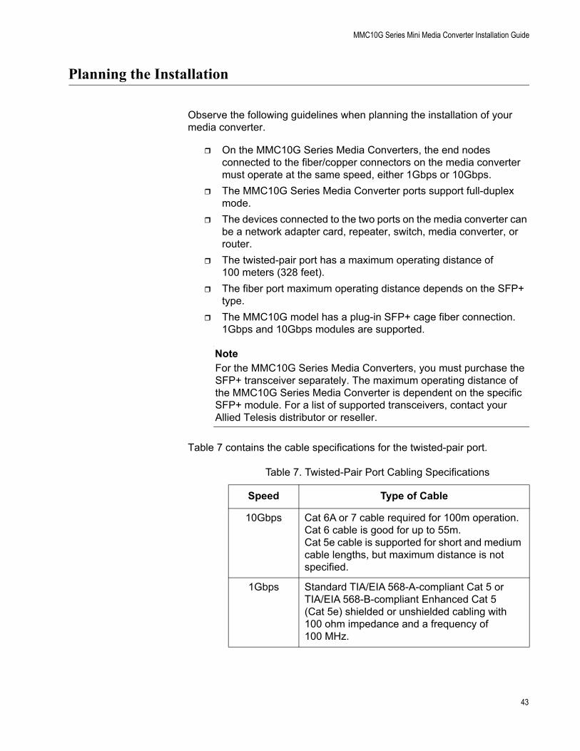
Table 7 contains the cable specifications for the twisted-pair port.
Table 7. Twisted-Pair Port Cabling Specifications
Speed Type of Cable
10Gbps Cat 6A or 7 cable required for 100m operation. Cat 6 cable is good for up to 55m. Cat 5e cable is supported for short and medium cable lengths, but maximum distance is not specified.
1Gbps Standard TIA/EIA 568-A-compliant Cat 5 or TIA/EIA 568-B-compliant Enhanced Cat 5 (Cat 5e) shielded or unshielded cabling with 100 ohm impedance and a frequency of 100 MHz.
43

Chapter 2: Beginning the Installation
NoteThe twisted-pair port on the MMC10GT/SP Media Converter features Auto MDI/MDI-X when operating at 1Gbps and 10Gbps. The port is configured as MDI or MDI-X when it is connected to an end node. Consequently, you can use a straight-through twisted-pair cable when connecting any type of network device to the twisted-pair port on the media converter.
44

MMC10G Series Mini Media Converter Installation Guide
Unpacking the Media Converter
To unpack the media converter, perform the following procedure:
1. Remove all of the components from the shipping package.
NoteStore the packaging material in a safe location. You must use the original shipping material if you need to return the unit to Allied Telesis.
2. Place the media converter on a level, secure surface.
3. In addition to the media converter, verify that the shipping container includes the following items. Figure 27 shows shipping container items for the MMC10GSP/SP and the MMC10GT/SP Media Converters.
Figure 27. Shipping Package Contents
One power adapter
Four rubber feet (adhesive type)
with four plugs
45

Chapter 2: Beginning the Installation
Supported Accessories
MMCWLMTWall Mount Kit
The MMCWLMT Wall Mount Kit is used for wall mounting. For installation instructions see “MMCWLMT Kit Installation” on page 52.
Figure 28. MMCWLMT Kit with Brackets
MMCR18Chassis Kit
The MMCR18 Chassis Kit is used as a power chassis. The MMCR18 rack-mount chassis provides rack-mount or desktop installation for up to 18 MMC Series Media Converters. The chassis is available in both AC and DC power supply units. For installation instructions, see Allied Telesis’ AT-MMCR18 Media Converter Rack-mount Chassis Installation Guide
46

MMC10G Series Mini Media Converter Installation Guide
NoteThe MMCR18 can support up to 12 MMC10G units with fiber SFP+ modules. The MMCR18 cannot support 18 MMC10G units, because of the higher power draw of the MMC10G compared to the MMC2000. Using copper SFP+ modules in the MMC10GSP/SP will further reduce the number of units supported, due to additional power requirements.
Figure 29. MMCR18 Rack-mount Chassis
MMCTRAY6Tray
The MMCTRAY6 Tray is used for rack mounting. The tray provides rack-mount installation for up to six MMC Series Media Converters. The tray itself does not provide power to the MMC Series Media Converters. For installation instructions, see Allied Telesis’ Installation Guide AT-MMCTRAY6 6-slot Tray for the MMC Series Media Converters.
Figure 30. MMCTRAY6 Tray
47

Chapter 2: Beginning the Installation
48

Chapter 3
Installation
This chapter contains the following sections:
“Installation Options” on page 50
“Desktop Installation” on page 51
“MMCWLMT Kit Installation” on page 52
49

Chapter 3: Installation
Installation Options
You may install the media converter on a desktop, wall or rack:
To install the media converter on a desktop, see “Desktop Installation,” next.
To install the media converter on a wall, see “MMCWLMT Kit Installation” on page 52.
NoteTo install the media converter on a wall, you must purchase the MMCWLMT Kit separately.
To install the media converter in a rack, see Allied Telesis’ AT-MMCR18 Media Converter Rack-mount Chassis Installation Guide. For another option to install the media converter in a rack, see Allied Telesis’ Installation Guide AT-MMCTRAY6 6-slot Tray for the MMC Series Media Converters.
50

MMC10G Series Mini Media Converter Installation Guide
Desktop Installation
To install the media converter on a desktop, perform the following procedure:
1. Place the media converter upside down on a flat, secure surface (such as a desk or table).
2. Affix the four adhesive rubber feet on the bottom of the media converter, one on each corner.
3. Turn the media converter right side up and place it on the desk or table, leaving ample space around the unit for ventilation.
4. Go to “Installing the SFP Transceiver” on page 58.
51

Chapter 3: Installation
MMCWLMT Kit Installation
Before installing an MMC10G Series Media Converter on a wall, you must have an MMCWLMT Kit that is provided separately.
1. Verify that the MMCWLMT Kit contains the items shown in Table 8.
2. Select a wall location for the unit.
3. Place the unit on a table.
Table 8 MMCWLMT Kit Contents
Description Illustration
5 Sets of Wall Mounting Brackets
20 Bracket Screws
20 Wall Mount Screws
20 Plastic Anchors
52

MMC10G Series Mini Media Converter Installation Guide
4. Orient the brackets against the sides of the unit, as shown inFigure 31, and secure them to the unit with the four of the brackets screws included.
Figure 31. Attaching the Brackets to the Media Converter
5. Print out the template in Figure 32.
Figure 32. Wall-mount Template
53
Chapter 3: Installation
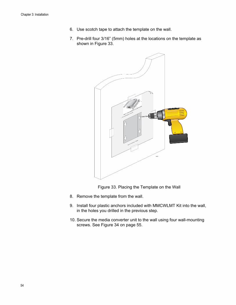
6. Use scotch tape to attach the template on the wall.
7. Pre-drill four 3/16” (5mm) holes at the locations on the template as shown in Figure 33.
Figure 33. Placing the Template on the Wall
8. Remove the template from the wall.
9. Install four plastic anchors included with MMCWLMT Kit into the wall, in the holes you drilled in the previous step.
10. Secure the media converter unit to the wall using four wall-mounting screws. See Figure 34 on page 55.
54

MMC10G Series Mini Media Converter Installation Guide
Figure 34. Securing the Media Converter to the Wall
11. Go to “Installing the SFP Transceiver” on page 58.
55

Chapter 3: Installation
56

Chapter 4
Powering On and Cabling the Media Converter
This chapter contains the following sections:
“Installing the SFP Transceiver” on page 58
“Powering On and Cabling the Media Converter” on page 60
57

Chapter 4: Powering On and Cabling the Media Converter
Installing the SFP Transceiver
To install an SFP transceiver, perform the following procedure:
NoteThe transceiver can be hot-swapped; you do not need to power off the media converter to install a transceiver. However, always remove the cable before removing the transceiver.
NoteYou should always install the transceiver before connecting the fiber-optic cable to it.
1. Remove the transceiver from its shipping container and store the packaging material in a safe location.
Warning
An SFP transceiver can be damaged by static electricity. Be sure to observe all standard electrostatic discharge (ESD) precautions, such as wearing an antistatic wrist strap, to avoid damaging the transceiver. E86
2. Position the SFP transceiver with the label facing up. Slide the transceiver into the SFP port until it clicks into place. See Figure 35.
Figure 35. Inserting the SFP
58
MMC10G Series Mini Media Converter Installation Guide
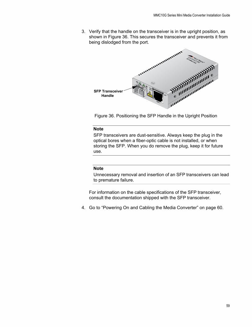
3. Verify that the handle on the transceiver is in the upright position, as shown in Figure 36. This secures the transceiver and prevents it from being dislodged from the port.
Figure 36. Positioning the SFP Handle in the Upright Position
NoteSFP transceivers are dust-sensitive. Always keep the plug in the optical bores when a fiber-optic cable is not installed, or when storing the SFP. When you do remove the plug, keep it for future use.
NoteUnnecessary removal and insertion of an SFP transceivers can lead to premature failure.
For information on the cable specifications of the SFP transceiver, consult the documentation shipped with the SFP transceiver.
4. Go to “Powering On and Cabling the Media Converter” on page 60.
SFP TransceiverHandle
59

Chapter 4: Powering On and Cabling the Media Converter
Powering On and Cabling the Media Converter
CablingGuidelines
Observe the following guidelines when connecting twisted-pair and fiber-optic cables to the ports on the media converter:
The connector on the cable should fit snugly into the port on the media converter. The tab on the connector should lock the connector into place.
Because the twisted-pair port has Auto MDI/MDI-X, you may use straight-through twisted-pair cable to connect any type of network device to that port.
For the fiber optic cables, refer to the cable manufacturer specification for the minimum bend radius.
Applying Powerand Connecting
the NetworkCables
To apply power to the media converter and connect the network cables, perform the following steps:
1. Plug the DC of the external power adapter to the power receptacle connector labeled 12VDC on the back panel of the media converter and turn the cord clockwise one-quarter turn to lock, as shown in Figure 37.
Figure 37. Connecting 12VDC Powered Unit
60

MMC10G Series Mini Media Converter Installation Guide
2. Plug the power adapter to a power outlet. Refer to “Power Specifications” on page 68 for power requirements.
3. Verify that the PWR LED is lit green. If the PWR LED is off, refer to “Troubleshooting” on page 63.
4. Verify that the SYS LED is lit green. If the SYS LED is off, refer to “Troubleshooting” on page 63.
5. If the media converter has a fiber-optic connector, remove the dust cover from the fiber-optic connector and connect the cable to the fiber-optic port.
6. For the MMC10GSP/SP model, repeat this step for the other fiber optic port.
7. For the MMC10GT/SP model, connect the twisted-pair cable to the twisted-pair port.
8. Power on the end nodes.
The media converter is now ready for use.
61

Chapter 4: Powering On and Cabling the Media Converter
62

Chapter 5
Troubleshooting
This chapter contains information on how to troubleshoot the media converter if a problem occurs.
NoteFor further assistance, please contact Allied Telesis Technical Support at www.alliedtelesis.com/support.
Problem 1: The PWR LED on the media converter is off.
Solutions: The unit is not receiving power. Try the following:
Verify that the power cord is securely connected to the power source and to the DC connector on the back panel of the media converter.
Verify that the power outlet has power by connecting another device to it.
Try using another power adapter of the same type that came with your media converter.
Verify that the voltage from the power source is within the required levels for your region.
Problem 2: The SYS LED on the media converter is off.
Solution: An internal component on the unit is damaged or not working properly. Try power cycling the unit. If power cycling does not clear the fault, return the unit to Allied Telesis.
Problem 3: The SYS LED on the media converter is blinking slowly.
Solutions: The media converter may be in Loopback mode or an error is present on the unit. Try power cycling the unit.
A transmit fault may be occurring on the SFP+ module. The media converter will try to clear this error, but if the error persists, try the following:
Remove and re-seat the SFP+ module.
Try a different SFP+ module.
Verify the SFP+ module is the correct type for your application.
63

Chapter 5: Troubleshooting
Problem 4: The twisted-pair Port 1 on the MMC10GT Media Converter is connected to an end node, but the port’s copper Port 1 LINK LED is off.
Solutions: The port is unable to establish a link to an end node. Try the following:
Verify that the end node connected to the twisted-pair port is powered on and is operating properly.
Verify that the twisted-pair cable is securely connected to the port on the media converter channel and to the port on the remote end-node.
Verify an SFP module is installed and recognized by the media converter (MMC10GT/SP).
Verify that the port is connected to the correct twisted-pair cable. This is to eliminate the possibility that the port is connected to the wrong end-node, such as a powered-off device.
Try connecting another end node to the twisted-pair port with a different cable. If the twisted-pair port is able to establish a link, then the problem is with the cable or the other end-node.
Verify that the twisted-pair cable does not exceed 100 meters (328 feet).
Verify that the end node connected to the media converter is operating at the same speed.
Verify that you are using the appropriate category of twisted-pair cable:
– 1G: Cat 5e
– 10G: Verify the cable length is not too long for the type of cabling used. See Table 7, “Twisted-Pair Port Cabling Specifications” on page 43.
NoteA connection may require 5 to 10 seconds to establish a link.
Problem 5: The LINK LED for an SFP+ port is off.
Solutions: The fiber-optic port on the transceiver is unable to establish a link to an end node. Try the following:
Verify that the end node connected to the fiber-optic port is operating properly.
Verify that the fiber-optic cable is securely connected to the port on the media converter and to the port on the remote end-node.
Verify that the end node connected to the media converter is operating at the same speed.
Check that the SFP+ module is fully inserted in the port.
64

MMC10G Series Mini Media Converter Installation Guide
Verify that the operating specifications and wave lengths of the fiber-optic port on the SFP+ transceiver and the remote end-node are compatible.
Verify that the correct type of fiber-optic cabling is being used.
Verify that the port is connected to the correct fiber-optic cable. This is to eliminate the possibility that the port is connected to the wrong remote end-node, such as a powered-off device.
Try connecting another end node to the fiber-optic port using a different cable. If the port is able to establish a link, then the problem is with the cable or with the other end node.
Verify that the fiber TX strand is connected to link partner's RX, and vice versa.
If the remote end node is a management device, use its management firmware to determine whether its port is enabled.
Test the attenuation on the fiber-optic cable with a fiber-optic tester to determine whether the optical signal is too weak (sensitivity) or too strong (maximum input power).
Problem 6: Fiber speed LED is blinking and alternating between green and amber (MMC10GT).
Solution: The media converter cannot detect the speed of the installed SFP. The copper port is disabled in this scenario.
Problem 7: Network traffic is not being received at the end point.
Solution: Verify cabling by using loopback mode attached to a managed switch port that can transmit test packets.
Problem 8: Loopback mode is not working.
Solution: Power unit off. Install (or re-seat) two 10G SFP+ modules. Power unit on and check loopback.
65

Chapter 5: Troubleshooting
66

Appendix A
Technical Specifications
Below are the technical specifications for the media converters. The specification categories are as follows:
“Physical Specifications”
“Environmental Specifications”
“Power Specifications” on page 68
“Safety and Electromagnetic Emissions Certifications” on page 68
“RJ45 Connector and Port Pinouts” on page 69
Physical Specifications
Figure 38. MMC10G Series Dimensions
Table 9. Physical Specifications
DimensionsW x D x H
5.6 cm x 10.2 cm x 2.2 cm(2.2 in x 4 in x 0.9 in)
Weight 170 g (6 oz)
67

Appendix A: Technical Specifications
Environmental Specifications
Power Specifications
The following specifications apply to the DC power connector on the media converter.
Safety and Electromagnetic Emissions Certifications
Table 10. Environmental Specifications
Operating Temperature MMC10GT/SP: 0° C to 40° C (32° F to 104° F)MMC10GSP/SP: 0° C to 50° C (32° F to 122° F)
Storage Temperature -15° C to 70° C (-5° F to 158° F)
Operating Humidity 5% to 90% non-condensing
Storage Humidity 5% to 95% non-condensing
Operating Altitude Range Up to 3,048 m (10,000 ft)
Table 11. Power Specifications
Input supply voltage 12 VDC
Maximum power draw 4.0 W
Maximum SFP+ power 1 W
Table 12. Safety and Electromagnetic Emissions Certifications
SafetyUL60950-1, EN60950-1, EN60825-1
Emissions (EMI)
FCC Part 15B Class A, CISPR 32 Class A, EN55032 Class A, RCM, VCCI Class A, ICES-003 Issue 6
ImmunityEN55024, EN61000-3-2, EN61000-3-3
Environmental ComplianceEU-RoHS compliant, WEEEChina RoHS compliant
68

MMC10G Series Mini Media Converter Installation Guide
RJ45 Connector and Port Pinouts
Figure 39 illustrates the pin layout for the RJ45 connector and port.
Figure 39. RJ45 Connector and Port Pin Layout
Table 13 lists the pin signals when a port is operating at 1Gbps or 10Gbps.
Table 13. Pin Signals (1Gbps or 10Gbps)
Pin Pair Signal
1 1 TX/RX+
2 1 TX/RX-
3 2 TX/RX+
4 3 TX/RX+
5 3 TX/RX-
6 2 TX/RX-
7 4 TX/RX+
8 4 TX/RX-
69

Appendix A: Technical Specifications
70