Embed Size (px)
Citation preview

Laser Film Digitizer
2905
Service GuidePart No.10309056
Array Corporation

ii
Copyright © 2001 Array Corporation All Rights Reserved
Windows, Windows 95, Windows 98, Windows NT, and Windows 2000 are registered trademarks in
the United States of Microsoft Corporation and each country.
Important :
1 No part of this manual may be copied or reprinted, in whole or in part, without written
permission.
2 The contents of this manual are subject to change without prior notice and without legal
obligation.
3 Caution:
Use of controls or adjustments or performance of procedures other than those specified
herein may result in hazardous radiation exposure.
Version 1E August 2001

iii
Safety Notices
This service guide is intended for service engineers who install or service the Film Digitizer model
2905. Read this manual before you install or service the Digitizer. Only technical service engineers
who are factory trained and authorized by the manufacturer are allowed to service the Digitizer.
Under no circumstances should any other person(s) remove covers or attempt to service this equip-
ment.
There is Helium Neon, (He-Ne) laser of 10mW used as the light source in the film digitizer. Never
look directly at or touch the laser beam.
Safety Precautions
1 Meaning of Signal Words
In this manual, signal words; DANGER, WARNING, CAUTION and NOTE are used regarding safe-
ty and other important instructions. These signal words and their meaning are defined as fol-
lows.
Please understand their meanings clearly before reading this manual.
Laser Safety :
This Model is certified as Class 1 laser product under the U.S. Department of
Health and Human Services (DHHS) Radiation Performance standard according to
the Radiation Control for Health and Safety Act of 1968. This means that the
Model does not produce Hazardous Laser radiation.
CDRH Regulation :
The Center for Devices and Radiological Health (CDRH), for the U.S. Food and
Drug Administration implemented regulations for laser products dated August
2,1976. These regulations apply to laser products manufactured from August
1,1996. Compliance is mandatory for products marked in the United States. The
Label shown in the following illustration indicates compliance with the CDRH reg-
ulations
And must be attached to the products marketed in the United States.
Danger : Indicates an imminently hazardous situation, which, if not avoided, will result in
death, serious injury, serious property damage, or occurrence of fire.

iv
Warning : Indicates a potentially hazardous situation, which, if not avoided, could result in
death, serious injury, serious property damage, or occurrence of fire.
Caution : Indicates a potentially hazardous situation, which, if not avoided, may result in
minor or moderate injury, property damage or loss of data.
Note : Indicates information of interest to users of this equipment as to exceptional con-
ditions or operating procedures.
2 Safety Precautions
Please observe the following precautions to ensure the safety of service engineers as
well as operators when using this equipment. Only technical service engineers who are
trained and authorized by the manufacturer are allowed to open the covers.
Danger
1 Do not use flammable gasses such as anesthetics or flammable liquids such as ethanol
near this equipment. Such gases may result in an explosion.
2 This equipment is equipped with a laser beam device as a light source. This laser can
cause serious injury when directly exposed to eyes and skin. Avoid exposure to the laser
beam.
3 Do not remove nor cancel any safety interlock switch. Such actions may result in serious
accidents.
4 This equipment contains high voltage components. Take precautions not to touch
those components. Otherwise, high voltages inside this equipment present a safety
hazard.
Warning
1 Avoid contact with the moving components of this equipment. It may result in severe
personal injury.
2 Do not use this equipment near other equipment, which may generate high frequen-
cies, or which may be affected by high frequencies. Doing so may result in malfunction
of this equipment or the other equipment.

v
3 Make sure that the main power of this equipment is turned OFF whenever the electric
parts are removed from the unit or attached to the unit. It is strictly prohibited to do
such engineering work without the main power being turned OFF. Doing so may cause
serious injury as well as failure of the electric parts.
4 It is strictly prohibited to modify this equipment in any way, remove any part, install any
part not so described by this manual. Failure to comply will result in voiding warranties
and potentially cause serious harm to service technicians and operators.
Caution
1 Prevent this equipment from experiencing severe shocks. Severe shocks may result in an
incorrect adjustment of optical and mechanical components in this equipment.
2 Do not use equipment such as a humidifier near or in the room where the equipment is
installed. If ignored, it could lead to a high humidity condition and condensation may
occur, which could impact the performance and operation of the equipment
3 Electrostatic charge may cause damage to the electronic circuits of this equipment. Be
cautious when handling or removing electronic parts during technical service.
4 Danger of explosion if the battery is incorrectly replaced. Replace only with the same or
equivalent type recommended by the manufacturer. Dispose of used batteries accord-
ing to the manufacturer's instruction. Observe all local and state standards for the
removal and disposal of batteries.
5 Use of controls, adjustments or performance of procedures other than those specified
in this manual may result in hazardous radiation exposure.
Note
1 Array Corporation assumes no responsibility or liability that results in injury or death if
any unauthorized or properly trained persons attempt to service or modify this equip-
ment in any way.
2 Should any the Warning Labels become illegible or get out of place, please contact your
authorized sales person immediately to have them replaced.

vi
Description of Labels
Labels on Outer Covers, (Labels for users)
(1)
(2)
(3)

vii
Labels Inside of the Main Unit, (Labels for maintenance or service)
(4)

viii
Location of Labels
1) Back Panel
(2)
(1)
(3)

ix
2) Inside, (Cover open)
(4)

x
Foreword
Object reader
This service guide is intended for authorized service engineers who installs or services 2905 laser
film digitizers. Read this guide thoroughly before attempting installation or servicing of this digi-
tizer.
Overview of this guide
Chapter 1 describes the equipment covered in this guide.
Chapter 2 describes the operative and environmental condition of the 2905 laser film digitizer.
Chapter 3 explains the method and procedures for the installation of the digitizer.
Chapter 4 describes necessary procedures for servicing the digitizer.
Chapter 5 describes the method and the procedure to check basic functions of the digitizer.
Chapter 6 shows a checklist for the quality evaluation.
Chapter 7 describes daily and routine maintenance checks.
Related material
Laser Film Digitizer 2905 User's Guide
2905 Scan Suite 3E User's Guide

xi
Chapter 1 Equipment Covered...............................................................................................1
Chapter 2 Operative and environmental condition .................................................................3
2.1 Installation environment .................................................................................4
2.2 Storage environment ......................................................................................5
2.3 Environmental condition of installation and equipment placement .................6
2.4 Transportation environment ...........................................................................7
2.5 The power requirement ..................................................................................8
Chapter 3 Installing the digitizer ............................................................................................9
3.1 Specifications ...............................................................................................11
3.2 Installation preparation ...............................................................................12
3.3 Unpacking and placement ............................................................................13
3.4 Confirmation of accessories .........................................................................14
3.5 Parts identification ........................................................................................15
3.6 Confirmation of input voltage ......................................................................16
3.7 Connection ..................................................................................................20
3.7.1 Connection of cables ............................................................................21
3.7.2 Setting of SCSI address .........................................................................21
3.8 Basic function check .....................................................................................22
3.8.1 Power on ..............................................................................................22
3.8.2 Installing scan application software .......................................................23
3.8.3 Confirming basic function .....................................................................24
3.9 Confirming the optical system .....................................................................26
3.9.1 Installation of Oscillo tool ......................................................................26
3.9.2 Start and termination of Oscillo tool ......................................................26
3.9.3 Calibration ............................................................................................27
Chapter 4 Services ...............................................................................................................31
4.1 Principle of operation ...................................................................................32
4.2 Principle of optical density measurement ......................................................38
4.3 Functions of each unit ..................................................................................39
Table of Contents

4.3.1 Functions of each circuit board .............................................................39
4.3.2 Functions of film detectors ...................................................................40
4.3.3 Detection of film size ............................................................................41
4.3.4 Calibration ............................................................................................42
4.4 Removing the unit covers etc. .....................................................................43
4.4.1 Removing the top plate .........................................................................43
4.4.2 How to access the electrical components ..............................................44
4.4.3 Checking or replacing the PC boards ....................................................46
4.4.4 Replacing the laser tube ........................................................................51
4.4.5 Replacing the laser power supply ..........................................................52
4.4.6 Confirmation of H-SYNC signal .............................................................53
4.4.7 Clearing films jam .................................................................................55
4.4.8 Checking the sensor movement ............................................................59
4.4.9 Checking the calibration operation .......................................................61
4.4.10 Cleaning the light collection cavity .......................................................62
4.5 Adjustment procedure .................................................................................63
4.5.1 Process when films are misaligned during transport ..............................63
4.5.2 Adjusting the mirror angle ....................................................................65
4.5.3 Checking the optical axis ......................................................................67
4.5.4 Adjusting the horizontal and vertical scanning (adjustment in factory) ...70
4.6 Exchanging the backup battery and setting CMOS .......................................71
4.6.1 Necessary equipment ............................................................................71
4.6.2 Battery exchange ..................................................................................72
4.6.3 Connecting the keyboard and the display .............................................74
4.6.4 Setting of CMOS ...................................................................................79
4.7 Creating and download method of LUT .......................................................83
4.7.1 Installing and deleting the LUT Tool ......................................................83
4.7.2 Starting and exiting the LUT Tool ..........................................................84
4.7.3 Updating the firmware ..........................................................................85
4.7.4 Creating the LUT ..................................................................................88
4.7.5 Checking the LUT .................................................................................97
4.8 Troubleshooting ...........................................................................................98
4.8.1 The POWER LED does not light ............................................................98
4.8.2 The READY LED continues blinking .......................................................98
4.8.3 The READY LED does not light ..............................................................99
xii

xiii
4.8.4 The operation of transportation mechanism does not stop ..................100
4.8.5 Film does not stop at the measurement starting position and is ejected 101
4.8.6 Film is not ejected ...............................................................................109
4.8.7 Film size is not correctly detected ........................................................109
4.8.8 The entire image looks black ...............................................................109
4.8.9 An irregular diagonal line not in the original film is seen in the scanned
image. ................................................................................................109
4.8.10 A stripe is displayed at a right angle from the horizontal scan ............110
4.8.11 The O.D. value of the image sandwiched between two transparent
sheets is incorrect ..............................................................................110
Chapter 5 Confirming basic operations ..............................................................................111
5.1 Checking the basic operation .....................................................................113
5.2 Calibration check .......................................................................................114
5.2.1 Confirmation of state of digitizers .......................................................114
5.2.2 Calibration ..........................................................................................115
5.2.3 Line Scan ............................................................................................118
5.3 Film size detection test ...............................................................................121
Chapter 6 Installation quality check sheet ..........................................................................123
6.1 The number of accessories .........................................................................124
6.2 The digitizer's power supply .......................................................................124
6.3 Basic operation ..........................................................................................125
6.4 Film size detection test ...............................................................................126
Chapter 7 Maintenance manual.........................................................................................127
7.1 Start-of-day and end-of-day checks ............................................................128
7.2 Regular check ............................................................................................128
Appendix Wiring diagram ..................................................................................................129

xiv

1
Chapter 1
Equipment Covered

Chapter 1 Equipment Covered
This service guide is applicable for the 2905 laser film digitizer.
2

3
Chapter 2
Operative and environmental condition

Chapter 2 Operative and environmental condition
2.1 Installation environment
Install the digitizer in the following range of temperature and humidity. When the humidity is low,
the static electricity is easily generated. Take care not to let the digitizer dewy.
Ambient temperature : 15-30C (in operation)
Ambient temperature inclination : 15c/h or less
Relative humidity : 30% - 75% (in operation)
50%-60% (best Condition)
The vibration and the impact : Do not drop and avoid strong shock.
Atmospheric pressure : 70-106kPa
When the humidity is low, static electricity is easily generated. Do not use equipment such as a
humidifier near or in the room where the equipment is installed. If ignored, it could lead to a high
humidity condition and condensation may occur, which could impact the performance and operation
of the equipment
Prevent this equipment from experiencing severe shocks. Severe shocks may result in an incorrect
adjustment of optical and mechanical components in this equipment.
4

Chapter 2 Operative and environmental condition
2.2 Storage environment
Ambient temperature : -10-40C
Ambient temperature inclination : 15C/h or less
Relative humidity : 10%-90% (no condensation)
The vibration and the impact : Do not drop and avoid strong shock.
Atmospheric pressure : 50-106kPa
5

Chapter 2 Operative and environmental condition
2.3 Environmental condition of installation and equipment placement
The 2905 film digitizer is designed for operation in a general office environment. Avoid installing and
operating the digitizer in the following places.
1 Places exposed to corrosive gas.
2 Places where the equipment may come in contact with water.
3 Places with much dust or sand.
4 Places with steam or other chemicals.
5 Places exposed to salt air.
6 Places subject to vibration or impact.
7 Places exposed to direct sunlight or direct heating ducts or elements.
8 Places with strong electromagnetic radiation.
9 Place where direct or indirect light reflects on the display screen of the host computer.
6

Chapter 2 Operative and environmental condition
2.4 Transportation environment
Ambient temperature : -10-50C
Ambient temperature inclination : 15C/h or less
Relative humidity : 10%-90% (no condensation)
The vibration and the impact : 1.1G or less
Atmospheric pressure : 50-106kPa
7

Chapter 2 Operative and environmental condition
2.5 The power requirement
Power voltage : Single phase 100-120Vac xA1.5-3, 200-240Vac xA1.5-3
Power frequency : 50/60Hz
8

9
Chapter 3
Installing the digitizer

Set up the digitizer in the place as described in Chapter 2"Operative and environmental condition" is
filled after confirmation of accessories in the box. Next, connect with the personal computer.
Operate the digitizer with the personal computer after inserting accessory's floppy disk in the per-
sonal computer, and confirm basic movement of the digitizer.
Confirm the connection of the digitizer before connects with the host computer and the personal
computer, and the overall, normal operation. Because neither this personal computer nor the SCSI
interface cable are included in the accessory of the digitizer; The service engineer has to prepare
them. Refer to paragraph 3.2"Installation preparation" for the specification of the personal comput-
er.
Chapter 3 Installing the digitizer
10

Chapter 3 Installing the digitizer
11
3.1 Specifications
Model Name Laser Film Digitizer 2905
Laser Source He Ne Laser, (632.8nm)
Film Size inch 14 X 17, 14 X 14, 11 X 14, 10 X 12, 8 X 10, 5 X 12
cm 30 X 40, 30 X 35, 30 X 30, 24 X 30, 24 X 24, 20 X 40,
18 X 43, 18 X 24, 15 X 40
other B4
Interfaces SCSI, SCSI II, TWAIN
Memory 128 Megabytes, (on board)
Pixel Size
Density Resolution 12 bits/pixel
Cycle Time
Density Calibration
Dimensions (W x D x H) 13 x 21 x 30 inch
Weight 45 Kg
Power Source 100~200V, 1.5-3A
200~240V, 1.5-3A
Operating Condition 15~30°C (59-86°F), 30~75% relative humidity (no condensa-
tion)
Preserve Condition -10~40°C (14~104°F), 10~90% RH (no condensation)
Transport Condition -10~50°C (14~122°F), 10~90% RH (no condensation)
Electromagnetic Resistance
Heat Generation
Applied Standard
Accessories 2905 User's Guide, Software Installation Disk, software User's
Guide, Power Cable
Optional Equipment

Chapter 3 Installing the digitizer
3.2 Installation preparation
(1) Standard work time
Installation (Chapter 3): one hour by two people
Basic function check (Chapter 5) and filling out the quality check sheet (Chapter 6): one hour by one
person
(2) Standard tool and measurement machine
Plus driver (for 2mm, 3mm, and 4mm)
Hex wrench (for 3mm and 4mm)
Voltmeter
(3) PC for function check
Windows 95, Windows 98, Windows ME, Windows NT 4.0, or Windows 2000 Operating System
(In case of Windows NT or Windows 2000, ASPI manager should be installed. For the detail of
ASPI manager, ask SCSI card manufacturer for the availability or see Web site of the card manu-
facturer)
3.5'' Floppy disk drive (1.44MB)
VGA 16bit-color or better display environment
18MB or more hard drive capacity
SCSI host adapter
SCSI interface cable(Digitizer SCSI Connector: Full pitch 50p)
SCSI terminator
12

Chapter 3 Installing the digitizer
3.3 Unpacking and placement
Caution : Two people should perform unpacking and moving because the weight of the
digitizer is over 45kg.
Use care to avoid any unnecessary shock when unpacking and moving the digitizer, as the optical
system and the film transportation mechanism in the digitizer are adjusted precisely.
1 Check of the packing material
Confirm there are no signs of damage to the packing material. If any signs are found, keep the pack-
ing material, and contact the distributor of the digitizer.
2 Unpacking
Open the package and remove the digitizer from the packing material respectively using two people
by gripping both sides of the equipment.
3 Placing the digitizer
Using two people, carry the digitizer to the area where it will placed for operation. Ensure clearance
from the wall of at least 20 cm and satisfy the condition described in Chapter 2
13
Chapter 3 Installing the digitizer
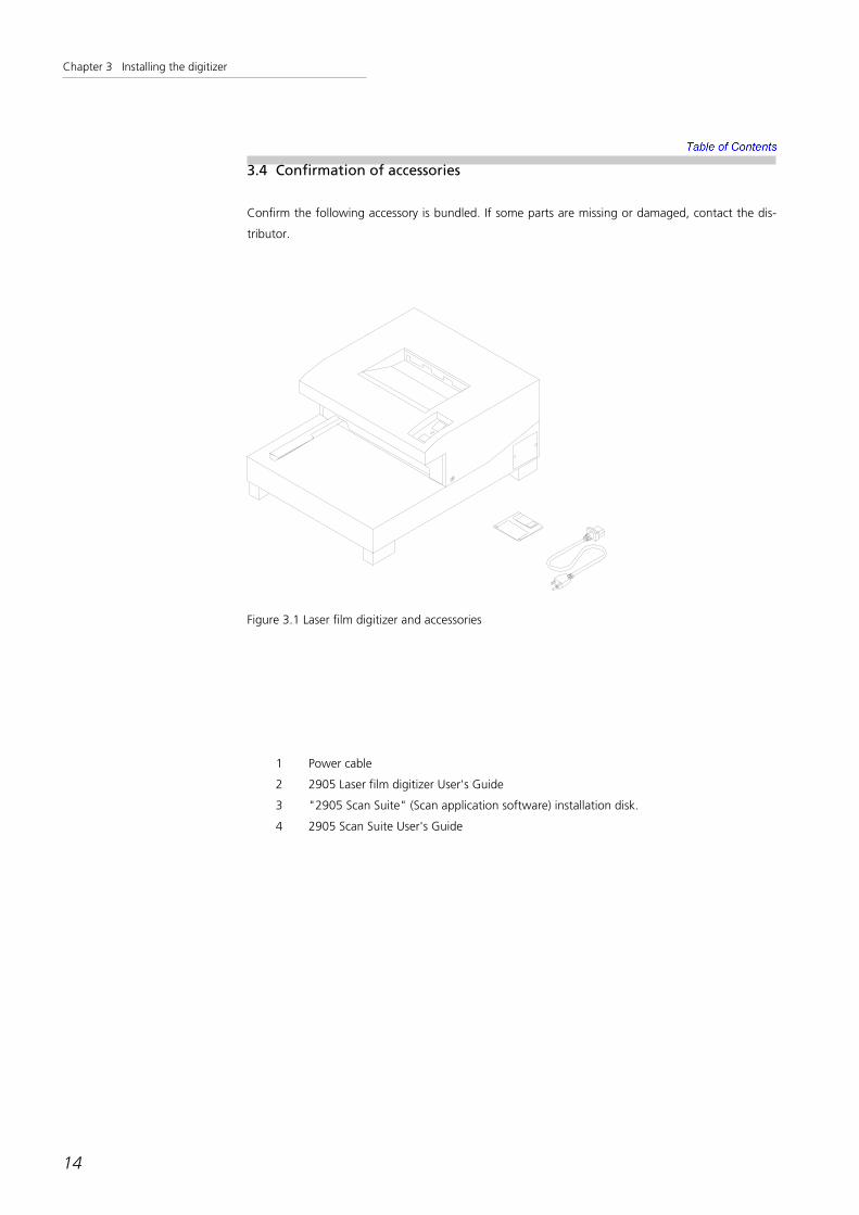
3.4 Confirmation of accessories
Confirm the following accessory is bundled. If some parts are missing or damaged, contact the dis-
tributor.
14
1 Power cable
2 2905 Laser film digitizer User's Guide
3 "2905 Scan Suite" (Scan application software) installation disk.
4 2905 Scan Suite User's Guide
Figure 3.1 Laser film digitizer and accessories

Chapter 3 Installing the digitizer
3.5 Parts identification
15
Ready Switch
POWER LED
READY LED
Eject Switch
Film Guide
Film Entrance Film Table
Figure 3.2 Name of parts (front)
SCSI Connector
Breaker
AC IN(inlet)
Figure 3.3 Name of parts (back)

Chapter 3 Installing the digitizer
3.6 Confirmation of input voltage
Confirm whether the setting of input voltage is correct before turning on the power supply.
1 Confirm SCSI cable and power cable are disconnected from the digitizer main body.
2 Remove five plus-screws on the back and four 4mm-hexagon socket screws on the bot-
tom.
16
Figure 3.4

Chapter 3 Installing the digitizer
3 As shown in Figure 3.5, slide out the electronics unit slowly taking care with internal
cables.
17
Figure 3.5

Chapter 3 Installing the digitizer
4 There is a voltage switch in the position shown in Figure 3.6. Confirm the setting of the
voltage is correct. If not, switch it to the correct voltage.
The following two voltages are supported:
100-120Vac xA1.5-3
200-240Vac xA1.5-3
18
Voltage Switch
Figure 3.6
Figure 3.7 2 varieties of the voltage setting

Chapter 3 Installing the digitizer
5 Put back the electronics unit, and secure all removed screws.
19

Chapter 3 Installing the digitizer
3.7 Connection
Connect SCSI cable with the digitizer and the PC and set the SCSI address.
20
Caution : Confirm the power switch of digitizer and PC are both turned off before connec-
tion.
Figure 3.8 Example of connection between digitizer and PC

Chapter 3 Installing the digitizer
3.7.1 Connection of cables
1 Connecting power cable
Connect power cable to the digitizer and power outlet.
2 Connecting SCSI cable
Connect SCSI cable between the digitizer and the PC.
3.7.2 Setting of SCSI address
The SCSI address is factory set to position 5. Change the set address number with the SCSI address
switch of the digitizer when it is necessary.
21

Chapter 3 Installing the digitizer
3.8 Basic function check
Install "2905 Scan Suite" (Scan application software) onto the PC. Once the software is installed,
open the application to ensure communication between the host PC and digitizer is working correct-
ly.
3.8.1 Power on
Turn on the power of the digitizer first, and then turn on the PC.
(When shutting the system down, the power to the PC must be turned off first, and then the power-
to the digitizer)
1 Digitizer power on
Turn on the power breaker located on the back of the digitizer and then turn on the power switch
located on the top of the unit.
Confirm the POWER LED is on, and in a few moments, the READY LED is also turned on. POWER
LED remains illuminated while the digitizer power is on.
READY LED is on only when the following five conditions are satisfied.
• The internal polygon mirror must rotate by a specified cycle.
• H-SYNC signal (signal which decides horizontal scanning timing) is generated correctly.
• Calibration is performed and the adjustment of high voltage to the photomultiplier is
normal.
• No film has been inserted in the digitizer.
• Data entry DMA function of sub-CPU is working normally.
2 PC Power on
Turn on the power of the PC.
22

Chapter 3 Installing the digitizer
3.8.2 Installing scan application software
Perform the following steps to install the scan application software into the PC.
1 Start the personal computer.
2 Insert the installation disk of "2905 Scan Suite" (Scan application software) in the floppy
disk drive of the PC.
3 Install software following the user's guide "2905 Scan Suite"
4 Remove the installation disk from the drive.
23

Chapter 3 Installing the digitizer
3.8.3 Confirming basic function
Perform the following steps to confirm the basic function of the digitizer.
1 Start of "2905 Scan Suite"
Follow the instructions in "2905 Scan Suite User's Guide" to start Scan application program. Press
"New Scan" to display the scan window.
2 Setting a film
Set a film into the digitizer. The digitizer detects the film and draws the film into the start position.
READY LED should be off at this time.
3 Confirm film ejection
Press EJECT button to eject film.
The transportation mechanism will start, and the film will be transported.
Press EJECT button again to stop ejecting the film.
Press EJECT once more to continue ejecting the film.
Confirm the film is transported smoothly without any unusual noise from the transportation mecha-
nism.
4 Scan
Set a film again and confirm the film is drawn and stops at the start position.
Click "Scan" button in the scan window to start scanning. The scanned image is displayed in the
mini-screen in the scan window.
When the scan is finished, the film is ejected automatically. The READY LED turns on.
24

Chapter 3 Installing the digitizer
5 Display of the film image
Click "Exit" button to display the image with the viewer. Use the viewer function to confirm the
image is scanned successfully.
25

Chapter 3 Installing the digitizer
3.9 Confirming the optical system
Confirm the optical system of the digitizer using the service software called "Oscillo tool" that dis-
plays the graph of the calibration data.
3.9.1 Installation of Oscillo tool
Perform the following steps to install the "Oscillo tool".
1 Insert the installation disk of the Oscillo tool into the floppy disk drive of the PC.
2 Copy the folder "Oscillo" located on the floppy disk into an arbitrary place on the PC's
hard disk.
3 Remove the floppy disk from the drive.
3.9.2 Start and termination of Oscillo tool
Double-click the file "Oscillo.exe" in the "Oscillo" folder on the hard drive to start "Oscillo tool".
26
Figure 3.9 The main window of Oscillo tool
Chapter 3 Installing the digitizer
To end "Oscillo tool", select "File-Exit" in the menu of the main window of "Oscillo tool".
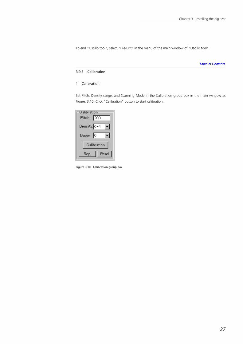
3.9.3 Calibration
1 Calibration
Set Pitch, Density range, and Scanning Mode in the Calibration group box in the main window as
Figure. 3.10. Click "Calibration" button to start calibration.
27
Figure 3.10 Calibration group box
Chapter 3 Installing the digitizer
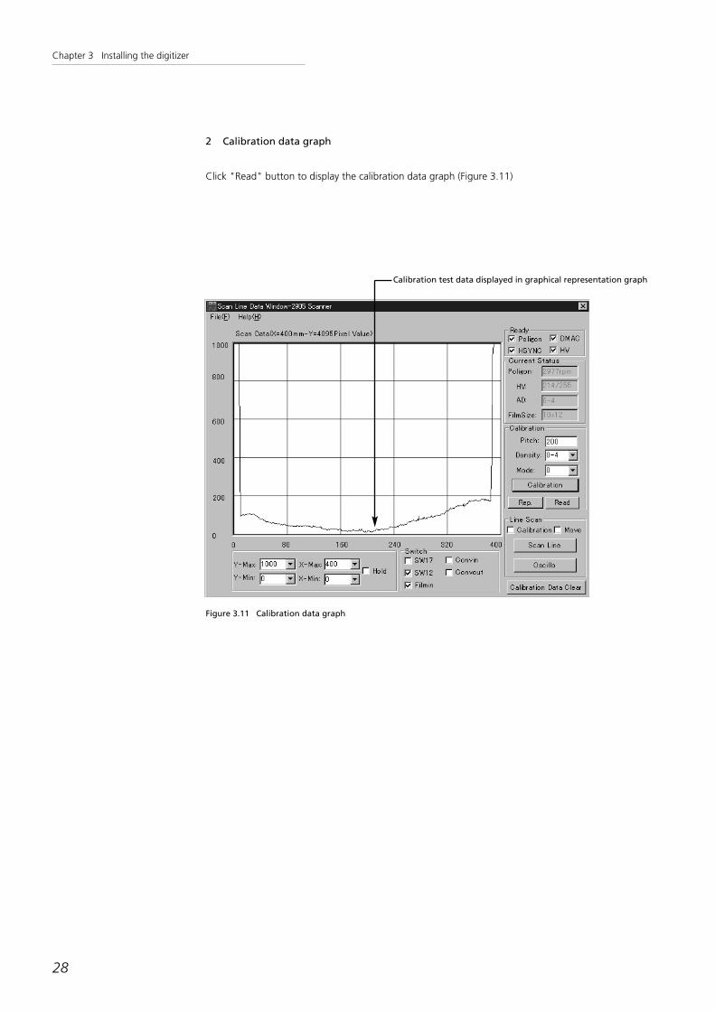
2 Calibration data graph
Click "Read" button to display the calibration data graph (Figure 3.11)
28
Calibration test data displayed in graphical representation graph
Figure 3.11 Calibration data graph

Chapter 3 Installing the digitizer
To change graph scales, change the values in the combo-boxes "x-min", "x-max", "y-min", "y-
max" under the graph.
29
Figure 3.12 Graph scale group box

Chapter 3 Installing the digitizer
If the graph is generally continuous without any significant peaks shown as Figure 3.11, the calibra-
tion data are good.
If the graph is like Figure 3.13, there may be dust in the cavity. Remove dust using compressed air
(see section 4.4.10 "Cleaning the light correction cavity").
If the graph is like Figure 3 14, there may be a problem in the light axis. Adjust the angle of the mir-
ror (see section 4.5.2 "Adjusting the mirror angle").
30
Figure 3.13 Calibration data graph, suggesting dust in the cavity
Figure 3.14 Calibration data graph, suggesting bad light axis

31
Chapter 4
Services

Chapter 4 Services
4.1 Principle of operation
The digitizer works by control command from the host computer. This control command is input via
SCSI cable which connects the digitizer with the host computer.
32
Digitizer
Host computer
Scan unit
Laser scanning unit
Safety circuit
Film transportation part
Control unit
Sub CPU unit
Film-size detector
Optical detector
A to D converter
Main CPU unit
Data memoryunit
Interface unit
Power supply unit
SCSI2 cable
DC POWER
CNT PCI bus
Figure 4.1 System block diagram

Chapter 4 Services
1 The laser beam emitted from the laser tube changes path/direction when reflecting off
the mirror, and is directed into the beam expander.
2 The beam expander reduces the extension angle of the laser beam.
3 Polygon mirror with eight facets scans the laser beam. The rotation speed of the polygon
mirror varies depending on the pixel spacing and scanning mode specified by the host
command.
33
Figure 4.2 Optical system

Chapter 4 Services
4 The f-theta lens converts the constant angular velocity scan to constant linear velocity.
5 By scanning this way, the image information of the film is converted to the intensity of
the transmitted laser beam.
6 The laser beam transmitted through the film passes through a slit, and enters into the
cavity.
The surface of the cavity is painted using special paint that reflects the light non-direc-
tionally at high reflectance rate.
In the cavity, the laser beam is reflected and diffused and passes through a light guide
and enters the photomultiplier.
The photomultiplier changes the intensity of the laser beam to electrical signals.
34
Figure 4.3 Function of f-theta lens

Chapter 4 Services
7 As shown in Figure 4.4, the film is transported in the direction of the arrow by the film
transportation mechanism using a five-phase pulse motor.
Horizontal scanning with polygon mirror and vertical scanning with film transportation
encompasses the scan of the whole film.
35
ScanningSub-scanning
Figure 4.4 Scanning and sub-scanning

Chapter 4 Services
8 The signal is converted to the log-scale with the log-amplifier to represent optical density.
9 A to D converter converts the analog signal to digital signal of 12 bits.
36
Mirror 4
Mirror 3
Host computer
I/F
Difference detection
Line buffer
SCSI cable
Calibration Buffer
Analog to digital conversion machine
Log amplifier
Photo multipliers
Light guide
CavityPhotometry part
Film
Roller
fθlens
Beam expander
Polygon mirror
Laser oscillator
Image memory
Mirror 1
Figure 4.5 Signal flow
Mirror 2
Chapter 4 Services
10 The digital data are written in the line buffer that keeps data for one scanline.
The line data in the line buffer is compared with the data in the calibration buffer that
keeps the one-line data acquired when the film does not exist.
11 The difference of line buffer and calibration buffer is calculated at each pixel position and
written into the difference buffer that represents the primitive pixel data at each pixel
position.
12 The pixel data in the difference buffer is converted to the final pixel data with look-up
tables (LUT).
The digitizer is originally equipped with a LUT to get the best optical density correction,
but arbitrary LUT can be downloaded from the host computer using control command.
The contents of the LUT are kept until the next download or the power-off.
When no LUT is downloaded, the original LUT is used for the pixel data conversion.
13 When the digitizer receives a data transfer command from the host computer, it sends
the pixel data of specified size to the host computer via SCSI interface.
37

Chapter 4 Services
4.2 Principle of optical density measurement
The principle of the optical density measurement of the film is as follows.
1 D1=-log(I1/I0) and D2=-log(I2/I0).
D1 represents the pixel data measured with the film
D2 represents the pixel data measured without the film
I0 represents standard light intensity at the photomultiplier
I1 represents the light intensity with the film
I2 represents the light intensity without the film
2 Optical density of the pixel D3 is calculated from these two values as follows:
D3=D2-D1=-log(I2/I1)
3 Therefore, the difference of the pixel data in the line buffer and the pixel data in the cali-
bration buffer represents the optical density at each pixel position.
38
Chapter 4 Services
4.3 Functions of each unit
4.3.1 Functions of each circuit board
1 Motherboard
PC-AT compatible main board, on which other boards are mounted.
• Main CPU
• 128MB memory
• Up to three PCI-bus cards or four ISA-bus cards
2 ADC board
Converts analog signal from the log-amplifier to digital data
• 12-bit ADC
• Range switch for the optical density range
• Control of the high voltage for photomultiplier
3 Flash memory card
• 7.95MB
• OS (MS-DOS) boot
• Firmware for main CPU and sub CPU
• Setting info
• Digitizer individual metric info
4 Sub-CPU board
Controls the mechanics of the digitizer and acquires the scan data.
• Acquires one-line data from ADC
• Performs pixel data averaging and subtraction
• Transfers pixel data to main memory
• Controls the rotation speed of polygon mirror
• Controls mechanics such as film transportation
• Detects the status of all switches and detectors
5 SCSI interface board
Interface for the host computer
• Fast SCSI-2 (10MB/s)
39

Chapter 4 Services
4.3.2 Functions of film detectors
Figure 4.6 shows the location of six film detectors.
Detector 1 and detector 2 are used to detect film size.
Detector 1: Detects the film whose vertical length is 40 cm or longer is set in the digitizer.
Detector 2: Detects the film whose vertical length is less than 35.5 cm is set in the digitiz-
er.
Detector 3: Detects the film is inserted to the digitizer. When this detector is on, the digi-
tizer starts to rotate the rollers to draw the film to the start position.
Detector 4: Located at the first roller. Detects the film is on the roller.
Detector 5: Located at the fourth roller. When the film is set to the digitizer, the digitizer
draws the film and stops when the film is detected.
The digitizer determines the film width by scanning one line of the film at this
position.
Then the digitizer rotates the roller to the opposite direction, acquiring scan
data and stops when the scan data shows the end of the film.
Detector 6: Located at the U-turn guide, detects the film is in the U-turn guide.
40
Detector 6
Detector 5
Detector 4
Detector 3 Detector 2 Detector 1
Figure 4.6 Arrangement of film detector

Chapter 4 Services
4.3.3 Detection of film size
The digitizer supports the following film sizes.
41
17 inch *14 inch (Portrait)
14 inch *14 inch
14 inch *11 inch (Portrait, Landscape)
12 inch * 10 inch (Portrait, Landscape)
10 inch * 8 inch (Portrait, Landscape)
5 inch * 12-inch (Portrait)
B4 (Portrait, Landscape)
18cm*43cm(Portrait)
30cm*40cm (Portrait)
20cm*40cm (Portrait)
15cm*40cm (Portrait)
30cm*35cm (Portrait, Landscape)
30cm*30cm
24cm*30cm (Portrait)
15cm*30cm (Portrait, Landscape)
24cm*24cm
18cm*24cm (Portrait)
When a film is set into the digitizer, the digitizer draws the film into the position of detector 5.
At this time, the digitizer scans one line and gets the horizontal length of the film with the scan data.
The digitizer then resets the film back to the start position of the scan.
When the film is at this position, the digitizer gets the vertical film size using detector 1 and 2.
Horizontal film size : The digitizer draws the film with the rollers until the detector
5 turns on.
The digitizer calculates the horizontal width of the film from
the scan data, pixel spacing, and correction constants.
Vertical film size : When the film is at the start position of scan, the digitizer
determines the vertical size of the film using the status of
detector 1 and 2.

Chapter 4 Services
4.3.4 Calibration
To get proper scan data, the digitizer adjusts the high voltage of the photomultiplier to know the
level of density 0.
This is called "Calibration."
The digitizer automatically performs the calibration each time before the scanning a film, and then
stores the averaged scan data when the film is not in the scan position of the calibration buffer.
The calibration is performed as follows:
1 The digitizer sets the high voltage of the photomultiplier to the initial value.
2 The digitizer scans the one line and sees if the pixel data at the center of the scan is suit-
able and register zero density.
3 If not, increase the high voltage by a certain step and repeat 2
The digitizer performs the calibration each time before the scan. This prevents any influence of of
laser intensity changes, analog circuit etc.
42

Chapter 4 Services
4.4 Removing the unit covers etc.
Danger : Turn off the power switch and the circuit breaker whenever you carry out opera-
tions such as removing the cover or servicing a unit.
4.4.1 Removing the top plate
You need to remove the top plate when checking the transportation mechanism or the laser's scan-
ning operation, or when cleaning the mirror.
Note : Because the interlock mechanism is installed on the digitizer, if the cover is
removed with the power and the circuit breaker switched on, laser beam radiation
and film transportation stop automatically.
Danger : The optical path of the laser beam can be observed when necessary by releasing
the interlock mechanism. However, never look directly at or touch the beam, as
serious injury could occur.
1 Detach a total five 4mm plus screws, three on the back of the top plate, one on the bot-
tom of the right side, and one on the bottom of the left side (Figure 4.7).
2 Carefully lift and remove the top plate from the main body. Now, the optical system and
the transportation unit can be checked.
43
Figure 4.7 Film digitizer from the back (angled)

Chapter 4 Services
4.4.2 How to access the electrical components
1 Remove the SCSI and power cables before pulling out the electrical component tray.
2 Pull out the electrical component tray by removing five plus screws on the back and four
4mm hexagon holed bolts on the bottom (Figure 4.8a).
44
Figure 4.8 a

Chapter 4 Services
3 Carefully pull out the electrical component tray. Take extra care not to stretch the cables
inside. The result looks like Figure 4.8 b.
45
Figure 4.8 b

Chapter 4 Services
4.4.3 Checking or replacing the PC boards
1 Remove four 3mm hexagon holed bolts, marked by arrows in Figure 4.9 (the top view of
the electrical component tray pulled out), to remove Shield Cover 1.
46
Shield cover 2
Shield cover 1
Shield cover 3
Figure 4.9 a

Chapter 4 Services
2 Remove four 3mm hexagon holed bolts, marked by arrows in Figure 4.9b, to remove
Shield Cover 2.
47
Shield cover 2
Shield cover 3
Figure 4.9 b

Chapter 4 Services
3 Remove the 3mm hexagon holed bolt marked by an arrow in Figure 4.9c, to remove the
DC constant-voltage supply.
48
Direct current constant-voltage power supply
Figure 4.9 c

Chapter 4 Services
4 To replace the PC board, first remove the connector attached to the board, then remove
the 3mm hexagon holed bolt marked by an arrow in Figure 4.9d, and carefully pull up
the board.
49
Figure 4.9 d

Chapter 4 Services
5 To replace the motherboard, remove all connectors connected to the motherboard, and
remove five screws marked by arrows in Figure 4.9e.
50
Figure 4.9 e

Chapter 4 Services
51
4.4.4 Replacing the laser tube
Danger : Take extra care on handling the connector that connects the laser tube and the
power supply. This connector has high voltage and improper handling could result
in serious injury or death.
Caution : Do not touch the mirror on the left of the laser tube. If touched, wipe it clean
with alcohol-dipped cotton buds etc.
After replacing the laser tube, bundle the cables together as before. Do not allow
the cables to cross the optical path of the laser beam.
The holder that secures the laser tube to the main body (part of the plinth of the
holder removed this time) is specified as an important connection. Under no cir-
cumstances should anyone move the holder except an engineer in charge from
our factory.
1 Remove two hexagon holed bolts that secure the connector holder (the holder that
secures the connection between the laser tube to the power supply) as shown in Figure
4.10.
2 Separate the connector.
3 Remove two hexagon holed bolts on the right and left holders that secure the laser tube
(total 4 bolts removed).
4 Replace the laser tube.
Mirror
Laser tube holderLaser power supply
Laser tube holder
Connector for the laser tube Connector holder Laser tube
Figure 4.10 Layout of the laser tube and the supply for laser

Chapter 4 Services
52
4.4.5 Replacing the laser power supply
1 Separate the connector from the power supply to the laser tube, as in section 4.4.4.
2 Remove the nylon connector of the DC12V input and the connector of the interlock
switch.
3 Remove two 3mm plus screws which secures the power supply for the laser.
4 Replace the power supply for the laser.

Chapter 4 Services
53
4.4.6 Confirmation of H-SYNC signal
H-SYNC signal is a signal that shows the start of horizontal scanning. It is extremely important since
the digitizer synchronizes its process with this signal.
The position of the H-SYNC board is shown in Figure 4.12, and its waveform in Figure 4.11.
Danger : Because the interlock mechanism is installed on the digitizer, if the cover is
removed with the power and the circuit breaker switched on, laser beam radiation
and film transportation stop automatically.
Danger : The optical path of the laser beam can be observed when necessary by releasing
the interlock mechanism. However, never look directly at or touch the beam, as
serious injury could occur.
1 Follow the procedure in section 4.4.1 to remove the top plate.
2 The interlock mechanism works and laser radiation stops. Disable the interlock mecha-
nism.
3 Connect the oscilloscope to the test pins
Two test pins stick out on the soldering face of the H-SYNC board. The pin with a blue
insulation bead is the test pin for the H-SYNC signal. The one with the black bead is for
grounding purpose. Connect the probe of the oscilloscope with this test pin.
As in Figure 4.11, the H-SYNC signal has its base on about -1.5V, and shakes from +15V
to -15V.
0v 0v
5v, 5μs DIV 5v, 0.5ms DIV
Figure 4.11 H-SYNC signal waveform

Chapter 4 Services
54
H-SYNC board Test pin
Figure 4.12 Position of the H-SYNC board

Chapter 4 Services
55
4.4.7 Clearing films jam
This digitizer is designed to read films of the following sizes.
17 inch *14 inch (Portrait)
14 inch *14 inch
14 inch *11 inch (Portrait, Landscape)
12 inch * 10 inch (Portrait, Landscape)
10 inch * 8 inch (Portrait, Landscape)
5 inch * 12-inch (Portrait)
B4 (Portrait, Landscape)
18cm*43cm(Portrait)
30cm*40cm (Portrait)
20cm*40cm (Portrait)
15cm*40cm (Portrait)
30cm*35cm (Portrait, Landscape)
30cm*30cm
24cm*30cm (Portrait)
15cm*30cm (Portrait, Landscape)
24cm*24cm
18cm*24cm (Portrait)
If a film of a size other than those listed above or a custom-processed film is used, the film might jam
or drop under the transportation roller. In this case, take out the film as follows:
Caution : The transportation unit has a timing pulley sticking out from the bottom. When
removing the transportation unit from the photometry unit and placing it on a
suitable resting surface etc., place it on two stands of 30mm or higher to avoid
the weight load resting on the pulley.
1 Follow the procedure in section 4.4.1 to detach the top plate.
2 Remove one connector and two nylon connectors that connect the photometry unit to
the transportation unit on the left of the digitizer.

Chapter 4 Services
56
3 Remove total six 4mm hexagon holed bolts which are showed on Figure 4.13a and
4.13b.
Caution : In order to reassemble correctly, before remove transportation unit, please make a
line between transportation unit and photometry unit.
Figure 4.13 a The position of the bolts securing the transportation unit to the photometry unit - left view
Figure 4.13 b The position of the bolts securing the transportation unit to the photometry unit - right view

Chapter 4 Services
57
4 As shown in Figure 4.14, remove two 4mm hexagon holed bolts on the left and two on
the right that secures the guide board to the transportation unit.
Any film dropped on the guide board underneath the roller can be removed.
Guide board
Figure 4.14 The position of the bolts that secure the guide board to the transportation unit

Chapter 4 Services
58
5 Remove two 4mm hexagon holed bolts on the left and two on the right that secures the
U-turn guides to the left and right sideboards of the transportation unit. Then remove
Sensor 6 and its actuator.
Now the film in the U-turn guide can be removed.
To secure the transportation unit to the photometry unit, reverse the above steps.
Afterwards, adjust the foremost edge of the film set on the photometry unit to be paral-
lel to the main scanner of the transportation unit.
U-turn guide
Figure 4.15 Securing bolt of the U-turn guide

Chapter 4 Services
59
4.4.8 Checking the sensor movement
A test program is provided to check that the six sensors shown in Figure 4.6 work properly. You can
feed the film inside the digitizer, and check whether each sensor can detect the film or not on the
display of the PC which executes the Oscillo tool.
1 Connection to the PC
Connect the digitizer to the PC, follow the steps in section 3.8.3 "Confirming basic func-
tion" and section 3.9 "Confirming the optical system".
Start the Oscillo tool.
2 Check the Switch group box
Make sure the five check boxes in the Switch group box in the main window are not
checked.
Figure 4.16 Main window of Oscillo tool
Switch group box

Chapter 4 Services
60
The correspondence of each check box and the sensor is as follows.
SW17 : Checked when there is a film in the position of detector 1.
SW12 : Checked when there is a film in the position of detector 2.
Filmin : Checked when there is a film in the position of detector 3.
Convin : Checked when there is a film in the position of detector 5.
Convout : Checked when there is a film in the position of detector 6.
Sensor 6
Sensor 5
Sensor 4
Sensor 3 Sensor 2 Sensor 1
Figure 4.17 Sensor layout
3 Set the film
Set the film in the digitizer and press the EJECT button. The film passes through the digi-
tizer and is ejected from the film outlet.
4 Check the sensors' operation
The operation of each sensor can be checked by the position of the film that passes
through the digitizer, and the colors of the circles drawn on the display.

Chapter 4 Services
61
4.4.9 Checking the calibration operation
As explained in section 4.3.4, each time the Start Scan command is input from the host computer,
the digitizer executes calibration and adjusts high voltage applied to the photo multipliers, prior to
the read operation of the film.
To check if calibration is executed properly, use the Oscillo tool to send the calibration command to
the digitizer and check the waveform on the main window of the Oscillo tool (See 3.9"Confirming
the optical system").

Chapter 4 Services
62
4.4.10 Cleaning the light collection cavity
If the digitizer is continually used for a long time, dust settles inside the cavity and affects the data.
To avoid this, dust in the cavity must be removed.
As explained in Figure 4-18, use compressed air to blow off the dust and suck it with a vacuum
cleaner. If this is insufficient to remove the dust, attach a nozzle to the vacuum and carefully insert it
inside the cavity and remove the remaining dust. Do not allow the tip of the nozzle to touch the
inner surface of the light collection cavity, as this may damage the surface.
Suck nozzle of the vacuum cleaner
Compressed Air
Figure 4.18 Cleaning the cavity

Chapter 4 Services
63
4.5 Adjustment procedure
4.5.1 Process when films are misaligned during transport
When attaching the transportation unit to the photometry unit, if the main scanning direction of the
transportation unit and the sub-scanning direction of the photometry unit do not form a right angle,
the films will be transported out of correct alignment. When this happens, adjust as follows:
Caution : Laser must be radiated during this adjustment. Make sure that you do not touch
or look directly into the laser beam.
Danger : The power of the digitizer's built-in laser is 10mW. The optical path of the laser
beam can be observed when necessary by releasing the interlock mechanism.
However, never look directly at or touch the beam, as serious injury could occur.
Note : Use an unnecessary film for this adjustment, because it might scratch the film.
1 Follow the procedure in section 4.4.1 to remove the top plate.
2 The interlock mechanism works and the laser radiation stops. Disable the interlock mech-
anism.
3 Loosen eight 4mm hexagon holed bolts securing the transportation unit to the photome-
try unit. Now, the installation angle of the transportation unit can be adjusted.
4 Set the film along the film guide and place it against the first roller.
5 Rotate the volume marked "STOP" on the bottom left of the driver board on the pulse
motor shown in Figure 4.19, counter-clockwise to the stop position. As a result, the lock
function (activated when the pulse motor stopped) is disabled.
6 Turn the pulley secured to the pulse motor axis carefully by hand to pull the film inside
the transportation unit. Move the film to the position where the tip of the film touches
the main scanning line.
7 Move the transportation unit slowly and carefully to match the main scanning line and
the front edge of the film.

Chapter 4 Services
64
Pulley STOP
Driver board for the pulse motor
Figure 4.19 Layout diagram of the pulley and the driver board

Chapter 4 Services
65
4.5.2 Adjusting the mirror angle
As explained in Figure 4.20, the laser beam is reflected on Mirror 3 and Mirror 4 and passed through
the center of the slit to scan the film. The laser beam, after it penetrates the film, is designed to hit
the photometry unit.
When the laser does not pass the center of the slit, adjust the angle of Mirror 4 as follows. When
performing this adjustment, make sure that you do not look directly at or touch the laser beam.
Furthermore, do not touch the mirror surface when moving the mirror.
Loosen the bolts left and right of the holder for Mirror 4, and adjust the angle of Mirror 4 to make
the main scanning line align to the center of the slit.
Caution : When adjusting the angle of the mirror, hold it with both hands. Do not touch
the surface. Touching the mirror may cause it to corrode in the future.
Mirror 4
Mirror 3
Slit 1Slit 2
Film
Photo multipliersLight guide
Cavity
Kodak 6080 application
Driving Roller
Figure 4.20 Laser Path (on normal operation)
Laser beam

Chapter 4 Services
66
1 Follow the procedure in section 4.4.1 to detach the top plate.
2 The interlock mechanism works and the laser radiation stops. Disable the interlock mech-
anism.
3 Loosen the two 4mm hexagon hold bolts each on the left and right securing the holder
for Mirror 4 to the sideboard.
4 Carefully look near Mirror 4 and adjust its angle so the laser beam passes the center of
the slit.
Grab the holder of Mirror 4 and adjust the angle without touching its surface.
Caution : If you touch the mirror surface and the image is affected, clean off the mirror with
alcohol-soaked gauze lightly without putting pressure on the mirror surface.
Mirror 4
Figure 4.21 Layout of Mirror 4 and driver board for the pulse motor
Hexagon holed bolt

Chapter 4 Services
67
4.5.3 Checking the optical axis
When the top board is removed (see section 4.4 for details), you can see a small mirror on the center
of the circle mark on Figure 4.22.
Figure 4.22 The position of the H-SYNC mirror

Chapter 4 Services
68
When you see the mirror from the direction shown on Figure 4.23, the sensor on the H-SYNC board
is reflected in the mirror (Figure 4.24 is an enlarged diagram). The optical axis is OK if the center of
the sensor is scanned by the laser beam. If the laser beam is off the receiving part of the sensor,
adjust the angle of the mirror by the steps explained in section 4.5.2. If the deviance is small, adjust
only Mirror 4.
Figure 4.23 The position and angle to see the H-SYNC sensor and laser beam reflected on the mirror

Chapter 4 Services
69
MirrorLaser beam
The sensor's detecting unit
Figure 4.24 The enlarged diagram of the H-SYNC sensor and laser beam reflected on the mirror

Chapter 4 Services
70
4.5.4 Adjusting the horizontal and vertical scanning (adjustment in factory)
This digitizer obtains and records a correction factor from the ratio of the distance measured with
the measuring machine and the distance measured with the digitizer. This correction factor is multi-
plied by the measured value of the digitizer to calculate the distance.
In this adjustment, a scan precision test film is prepared in the following steps:
• The interval of the line in the main scanning direction and the sub scanning direction is
measured with a measuring instrument.
• This measurement value is recorded on flash memory card.
• The test program is executed. The digitizer reads the entire surface of the test film.
• The correction factor is calculated and recorded on the flash memory, from the pixel
spacing between the lines and the spacing measured by the digitizer and the values from
the measuring instrument.
• To measure the distance between the lines on another film, multiply the value from the
digitizer and the correction factor to measure the true distance.
The correction factor for each pixel spacing is recorded on a flash memory card, so when the card is
replaced, the factors must be re-measured.
1 Connect to the PC
Connect the digitizer and the PC according to section 3.7 "Connection", and start the
test program.
2 Select in the test program
Select "Setting of the correction factor" in the test program.
3 Set the film
Set the film for the scanning accuracy test in the digitizer.
4 Click the START button
Click the "START" button of the test program.
The digitizer reads the film. Then the correction factor is calculated from the value meas-
ured by the digitizer and the value by the measuring instrument (recorded on the flash
memory card). Finally, the correction factor is overwritten on the flash memory card.
If you prefer not to use the test film and use the film with no measuring instrument data
recorded on the flash memory card, you must enter the values that correspond to the
measurement machine values manually from the keyboard.
Chapter 4 Services
71
4.6 Exchanging the backup battery and setting CMOS
4.6.1 Necessary equipment
Prepare the following items before starting this procedure.
1 Keyboard (PS/2 not acceptable)
2 PCI Video board that support VGA display
3 Monitor that support VGA display
4 Battery for exchange (CR2032)

Chapter 4 Services
72
4.6.2 Battery exchange
Follow the procedure in section 4.4 "Removing the unit covers etc." to uncover the battery (Figure
4.25, 4.26).
Battery
Figure 4.25 Position of the battery on the motherboard

Chapter 4 Services
73
Push out the place pointed by an arrow on Figure 4.26a with a sharp instrument to make the result
look like Figure 4.26b, to pick up the battery with your finger.
After removing the old battery, insert the new battery as shown in Figure 4.26b to make the result
look like 4.26a.
When battery exchange is completed, check the voltage using a battery checker. Normally the volt-
age will be about 3.2 V.
a b
Figure 4.26 How to remove the battery
Note : The voltage is about 3.2V immediately after supplying a new battery, but when
used over a day, the voltage usually remains at approximately 3V.

Chapter 4 Services
74
4.6.3 Connecting the keyboard and the display
1 The connector of the keyboard is under the direct current constant-voltage power supply
part (Figure 4.27). Remove four hexagon holed bolts, and lift and move the direct current
constant-voltage power supply part (Figure 4.28) to access the connector.
Direct current constant-voltage power supply
Figure 4.27 Remove the bolts securing the direct current constant-voltage power supply

Chapter 4 Services
75
Keyboard connector
Figure 4.28 Make the keyboard connector usable

Chapter 4 Services
76
2 Remove one 3mm hexagon holed bolt as shown in Figure 4.29 and remove the shield
bracket. Insert a video board in the PCI bus as shown in Figure 4.30.
Figure 4.29 Remove the shield bracket

Chapter 4 Services
77
Video board
Figure 4.30 Insert a video board in PCI bus
Chapter 4 Services
78
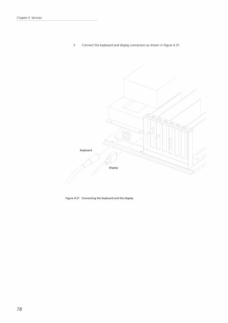
3 Connect the keyboard and display connectors as shown in Figure 4.31.
Keyboard
Display
Figure 4.31 Connecting the keyboard and the display
Chapter 4 Services
79
4.6.4 Setting of CMOS
CMOS is a battery-backed-up SRAM that stores the various setting characteristics of the BIOS.
(1) Start of CMOS setting program
Turn on the power supply of the digitizer after confirming that the electronics unit and all connec-
tions are safe. Push the "Delete" key on the keyboard when the memory test is completed. CMOS
setting program starts.
(2) About each screen
1 Initial screen
The following settings exist. Italicized items need to be set or confirmed.
STANDARD CMOS SETUP
BIOS FEATURES SETUP
CHIPSET FEATURES SETUP
POWER MANAGEMENT SETUP
PNP/PCI CONFIGURATION
LOAD SETUP DEFAULTS
INTEGRATED PERIPHERALS
SUPERVISOR PASSWORD
USER PASSWORD
IDE HDD AUTO DETECTION
HDD LOW LEVEL FORMAT
SAVE & EXIT SETUP
EXIT WITHOUT SAVING
Some settings on each screen are influenced by other settings. For example, if one set-
ting is changed, another setting might appear, or a setting may disappear.
Press the "ESC" key to return from the setting screen of the each item to the initial
screen.

Chapter 4 Services
80
2 STANDARD CMOS SETUP
Date(mm:dd:yy) : xx, xx xx xxxx -> Set the date
Time(hh:mm:ss) : xx : xx : xx -> Set the time
HARD DISK
Primary Master : None
Primary Slave : None
Secondary Master : None
Secondary Slave : None
Drive A : None
Drive B : None
Video : EGA/VGA
Halt On : No Errors
3 BIOS FEATURES SETUP
Value Warning : Disabled Video Bios Shadow : Enabled
CPU Internal Cache : Enabled C8000-CBFFF Shadow : Disabled
External Cache : Enabled CC000-CFFFF Shadow : Disabled
Quick Power On Self Test : Enabled D0000-D3FFF Shadow : Disabled
Boot Sequence : C,A,SCSI D4000-D7FFF Shadow : Disabled
Swap Floppy Drive : Disabled D8000-DBFFF Shadow : Disabled
DC000-DFFFF Shadow : Disabled
Boot Up Numlock Status : On
Boot Up System Speed : High
Typematic Rate Setting : Disabled
Typematic Rate (Chars/Sec) : 6
Typematic Delay (Msec) : 250
Security Option : Setup
PS/2 mouse function Control : Enabled
PCI/VGA Palette Snoop : Disabled
Assign IRQ For VGA : Enabled
OS Select for DRAM > 64 MB : Non-OS2
Report No. FDD For WIN95 : No

Chapter 4 Services
81
4 CHIPSET FEATURES SETUP
Auto Configuration : Enabled
DRAM Timing : 60ns
DRAM Leadoff Timing : 10/6/3
DRAM Read Burst (EDO/FP) : X222/X333
DRAM Write Burst Timing : X222
Fast EDO Lead Off : Enabled
Refresh RAS# Assertion : 4 Clks
Fast RAS to CAS Delay : 3
Fast MA to RAS# Delay : 2 Clks
SDRAM (CAS Lat/RAS-to-CAS) : 3/3
SDRAM Speculative Read : Disabled
System BIOS Cacheable : Disabled
Vide BIOS Cacheable : Disabled
8 Bit I/O Recovery Time : 1
16 Bit I/O Recovery Time : 2
Memory Hole At 15M-16M : Disabled
PCI Passive Release : Disabled
5 POWER MANAGEMENT SETUP
Power Management : Disabled
Other settings are optional.
6 PNP/PCI CONFIGURATION SETUP
PNP OS Installed : No PCI ISE IRQ Map To : PCI-AUTO
Resources Controlled By : Auto Primary IDE INT# : A
Reset Configuration Data : Disabled Secondary IDE INT# : B
Assign IRQ For USB : Enabled
Set automatically

Chapter 4 Services
82
7 INTEGRATED PERIPHERALS
IDE HDD Block Mode : Enabled Parallel Port Mode : Normal
IDE Primary Master UDMA : Auto
IDE Primary Slave UDMA : Auto
IDE Secondary Master UDMA : Auto
IDE Secondary Slave UDMA : Auto
On-Chip Primary PCI IDE : Disabled
On-Chip Secondary PCI IDE : Disabled
USB Keyboard Support : Disabled
Onboard FDD Controller : Disabled
Onboard Serial Port 1 : Auto
Onboard Serial Port 2 : Auto
UART2 Mode : Standard
Onboard Parallel Port : 378/IRQ7
8 SAVE & EXIT SETUP
When this item is selected, the following message to confirm whether or not to save
the setting appears.
SAVE to CMOS and EXIT(Y/N)?
Type 'Y' and press the Enter key to save the settings.

Chapter 4 Services
83
4.7 Creating and download method of LUT
A Lookup table (LUT) based on the film specifically used for the optical density calibration can be cre-
ated and registered in the digitizer. The LUTCreate tool software is used with the calibration film as a
means of registering the LUT in the digitizer. The LUT created can be downloaded to the flash mem-
ory card in the digitizer with the LUTCreate tool.
Caution : Only digitizers with and after Serial No. 184 are capable of adjusting optical densi-
ty with the LUTCreate tool. Attempts to adjust optical density on older machines,
(before serial number 184), the digitizer will not be able to read the optical densi-
ty properly. The serial number seal is found on the back of all machines.
Figure 4.32 Plate on the back
Plate
4.7.1 Installing and deleting the LUT Tool
1 Installing the LUT Tool
Copy the folder having the "LUTCrate.exe" to any place in your hard drive.
• System requirements
Operating system : Windows 95, Windows 98, Windows NT4.0
• Don't delete any files or sub folders inside the folder containing the LUTCreate.exe. This
may result in the LUT Create tool not working properly.
2 Deleting the LUT Tool
Drop the folder having the "LUTCreate.exe" into Recycle Bin.

Chapter 4 Services
84
4.7.2 Starting and exiting the LUT Tool
1 Boot the 2905 and the computer connected the 2905(see Section 3.8.3, "Confirming
basic function").
2 Double-click the icon labeled "LUTCreate.exe".
The 2905 LUT Create tool is started, and its main window is displayed on the screen.
Figure 4.33 Main window - 2905 LUT Create tool
3 To exit from the tool, click the "Exit" button.

Chapter 4 Services
85
4.7.3 Updating the firmware
Before creating LUT using the 2905 LUT Create tool, you must update the 2905 firmware.
The three files to be updated are "lut_linear.dat" for LUT, "Sub_firm.ima" for the sub CPU and
"As2905.exe" for the main CPU.
Once the firmware update is completed, you do not need to update the firmware again.
(1) Downloading the "lut_linear.dat"
1 Double-click the "LUTCreate.exe" icon to start the 2905 LUT Create tool.
2 On the main window, click the "Scanner" button to open the Scan dialog box.
Figure 4.34 Scan dialog box

Chapter 4 Services
86
3 On the Scan dialog box, select the "File" menu -> the "File Download" submenu -> the
"LUT Download" item.
The dialog titled "File Dialog for Download LUT File to the Scanner" opens.
Figure 4.35 The dialog titled "File Dialog for Download LUT File to the Scanner"
4 From the "Look in" combo box, go to the folder that contains the file labeled "lut_lin-
ear.dat", and select the "lut_linear.dat".
5 Click the "Open" button.

Chapter 4 Services
87
(2) Updating the sub CPU
1 On the Scan dialog box, select the "File" menu -> the "File Download" submenu -> the
"Firmware Download" item.
The dialog titled "File Dialog for Update Sub-CPU firm to the Scanner" opens.
2 From the "Look in" combo box, go to the folder that contains the file labeled
"Sub_firm.ima", and select the "Sub_firm.ima".
3 Click the "Open" button.
Caution : Wait until the next dialog box opens automatically. Otherwise, the 2905 may mal-
function.
(3) Updating the main CPU
1 The dialog titled "File Dialog for Update main CPU to the Scanner" opens. This time,
select the file labeled "As2905.exe".
2 Click the "Open" button.
3 The dialog box with the "Please Power-On the Scanner" message is displayed on the
screen. Click the "OK" button and reboot 2905.
(Turn off the Power Switch, wait 10 seconds, and turn on the Power Switch again)
4 Click the "Exit" button to close the Scan dialog box.
Now the firmware is updated. To exit from the application, select "File" menu -> "Exit" from the
main window.

Chapter 4 Services
88
4.7.4 Creating the LUT
(1) Scanning the Film
a Using LUT Create Tool
• LUT Create Tool downloads lut_linear.dat into 2905 automatically when scanning the
film with LUT Create Tool.
1 Click the "Scanner" button.
The Scan dialog box is displayed on the screen.
Figure 4.36 Scan dialog box

Chapter 4 Services
89
2 Set the scan region. Measure the region to modify the density data on the film, and fill
in the "Left", "Top", "Width", and "Height" text boxes so the region to modify the
density is displayed on the main window's mini-screen.
• If the "Width" is larger than 50mm, the image displayed on the mini-screen may be
incorrect. If this is the case, reset the width to 50mm or less.
3 On the "Pitch" combo box, set the pixel spacing. Usually, select 50 µm.
4 On the "Density" combo box, set the O.D. range. Usually, select "0-4".
5 Click the "Scan" button.
The scan begins.
6 When the scan is completed, the color of the "Exit" button changes from gray to black.
Click the button to close the Scan dialog box.

Chapter 4 Services
90
b Using the other scan tool attached 2905
1 Download Lut_linear.dat into the 2905(see "4.7.3 Updating the firmware").
2 Exit LUT Create tool.
3 Scan the film.
Scan condition: Depth 12bits Smooth standard Pitch 50µm Density 0-4
• If the "Width" is larger than 50mm, the image displayed on the mini-screen may be
incorrect. If this is the case, reset the width to 50mm or less.
4 Save the scanned file as tiff file. Name the tiff file "test + Density.tif".
For example, name the tiff file scanned in 0-4 density ,"test4.tif".
5 Move the tiff file into the folder containing the LUTCreate.exe.
6 Restart LUT Create tool.
The scanned image is displayed on the mini-screen.

Chapter 4 Services
91
(2) Setting the O.D. Range
1 On the "AD Voltage" combo box, set the AD voltage of the A/D board in the 2905.
2 On the "O.D." combo box, select the O.D. value corresponding the AD voltage.
Select "4.0" for the AD voltage "4.4".
* Select "3.0" for the AD Voltage "3.3", "2.0" for "2.2", and "1.0" for "1.1".

Chapter 4 Services
92
(3) Entering the target O.D. values for each step
1 On the "Step" combo box, select the number of steps to have the LUT created.
* If you click the combo box, a cursor is displayed and any desired value can be entered.
2 Enter the target value to the I th step text box, for I from 0 to the number indicated in
the Step combo box.
Enter value of 0 to the last step combo box.
Caution : Do not use a step over the range that you set the O.D. Range in the combo box
Use a lower density step if differences of O.D. will be less than 0.03
Example:
Step 6 and Step 7 are over range, then do not use them.
Step 1 and Step 2 are close each other less than 0.03. Step 1 is lower density than Step
2, then use it.
step 0 1 2 3 4 5 6 7
film having target value 0.51 0.53 1.5 2.37 3.48 4 4.36
� � � � � � �
value of enter step text box 0 0.51 1.5 2.37 3.48
enter 5 into "step" combo box
* If you saved the measured pixel value and target O.D. value to CSV file, you can set those
saved data.(see "(4) Entering the measured pixel values for each step")
1 Click the "ReadFile" button. The dialog titled "File Dialog for Read sample and AD
data" opens.
2 Select the .csv file you saved and click the "Open" button.

Chapter 4 Services
93
(4) Entering the measured pixel values for each step
1 For each step of the image displayed on the mini-screen, create the marquee by dragging
inside the image.
Figure 4.37 Marquee
2 Click the text box that contains the Pixel value for the step you created using the mar-
quee.
The average Pixel value (displayed on the "mean" field) is automatically entered on the
"Scan Data" text box.
3 Since LUT Create Tool scans film by 12bits, enter 4095 to the text box associated to the
"step" text box having value of 0.
• The values can be adjusted manually, if needed.

Chapter 4 Services
94
4 When you finish entering the pixel value, you might want to save the measured pixel
value and target O.D. value by clicking the "SaveFile" button.
The dialog titled "File Dialog for Write sample and AD data to File" opens.
Figure 4.38 The dialog titled "File Dialog for Write sample and AD data to File"
Save the data as .csv file.
* If the entries are saved, the same values are displayed the next time you click the
"ReadFile" button (see "(3) Entering the target O.D. values for each step" ).
5 On the "Closely Method" combo box, select the creation method of the LUT. Usually,
select "Line Graph".
* The "Average" option creates LUT by averaging the values set on each step. The "Line
Graph" option uses the values set on each step "as is". First use "Line Graph"; if that
does not work well, try "Average".

Chapter 4 Services
95
(5) Creating and saving the LUT file
The newly configured LUT can be saved as a file and downloaded into the 2905.
1 Click the "Create LUT" button.
2 Four message boxes titled "LUTCREATE" are displayed consecutively. Click "OK" for all
of them.
An LUT file is created in the same folder as LUTCreate.exe, and a graph is displayed,
based on the "Closely Method" combo box setting.
3 Click the "Save LUT File" button.
4 A dialog box with the "Save LUT(0-1.0-2.0-3.0-4) to file?" message is displayed on the
screen. Click "OK".
A dialog box titled "File Dialog for Write LUT to File" opens.
5 On the "Save in" combo box, select the location to save the LUT file.
6 In the "File Name" text box, enter any file name, without extension (the file extension is
added automatically).
7 Click the "Save" button.

Chapter 4 Services
96
(6) Downloading the LUT file
1 Click the "Scanner" button.
2 The Scan dialog box opens.
3 On the Scan dialog box, select the "File" menu -> the "File Download" submenu -> the
"Download LUT" item.
4 A dialog box titled "File Dialog for Download LUT file to the Scanner" opens.
5 On the "Look in" combo box, select the LUT file name.
6 Click the "Open" button.
7 The new LUT file is downloaded into the 2905.
When the download of the LUT file is completed, exit from the 2905 LUT Create tool.

Chapter 4 Services
97
4.7.5 Checking the LUT
1 Download the LUT data into 2905 and scan the film that was used to create the LUT
data.
2 Check the measured value of every step.
The tolerable value must be between target value - 0.2 and target value + 0.2.
* If the target value of the step is out of O.D. range (check the "O.D. combo box"), com-
pare the measured value with the max value of O.D. range.

Chapter 4 Services
98
4.8 Troubleshooting
4.8.1 The POWER LED does not light
The POWER LED lights only when power is supplied to the digitizer.
1 Check that the power cable of the digitizer is correctly connected with the outlet.
2 Check that the circuit breaker in the back of the digitizer is on.
3 Check that the power switch in the upper part of the digitizer is on.
4.8.2 The READY LED continues blinking
When the power supply of the digitizer is turned on, the motherboard and the sub-CPU board exe-
cute the following process. During the process, the READY LED blinks. The process normally ends in
about 30 seconds.
1 When the power supply of the digitizer is turned on, a reset signal is generated and sent
to the motherboard and the sub-CPU board.
When the motherboard receives this signal, it executes its initializing operation, such as a
memory test.
2 The motherboard loads the operating system from the flash memory card to the main
memory, and executes it.
3 This firmware loads the firmware for sub-CPU from the flash memory card into the main
memory, and furthermore, directs the sub-CPU to download the firmware for the sub-
CPU in the main memory.
4 The firmware for the motherboard initializes the SCSI interface, and commands the sub-
CPU board to start.
5 When the sub-CPU board receives the reset signal, it begins to execute the ROM pro-
gram. It blinks the READY LED and waits for the instruction of the download of the
firmware from the motherboard.
6 When the sub-CPU receives the instruction from the motherboard, it downloads the
firmware for itself from the main memory, and executes hardware test and initialization.
7 The sub-CPU waits for the start instruction from the motherboard.
8 When the sub-CPU receives the start signal, sub-CPU board discontinues blinking the
READY LED, and executes the film eject operation.
9 When six sensors do not detect the film, sub-CPU board stops the operation of the trans-
portation mechanism. If the status meets the requirements in Section 4.8.3, the READY
LED turns on.

Chapter 4 Services
99
If the READY LED blinks for more than 30 seconds, there may be a failure in either the motherboard,
the sub-CPU board, or the flash memory card.
From the past examples, the number one cause is the battery backup of the motherboard.
Cause (1) The motherboard's battery (CR2032, 3.0V) fell below 3.0V and the CMOS
data was reset.
Procedure (1) Replace the battery and re-set the CMOS data. (See "4.6 Exchanging the
backup battery and setting CMOS")
Cause (2) The voltage of the motherboard battery is about 3V, but the CMOS data was
reset by other causes (thunder, static charge, noise in AC input supply, bad
contact of the battery, etc.)
Procedure (2) See Section 4.6 to re-set the CMOS data.
4.8.3 The READY LED does not light
The READY LED lights only while all the following of the five conditions are being satisfied.
• The polygon mirror must be rotating by a specified cycle.
• H-SYNC signal (signal which decides the timing of horizontal scan) is normally generated.
• Calibration is already executed, and the adjustment of high voltage to the photo multipli-
ers is OK.
• A film has NOT been inserted in the digitizer.
• Data entry DMA function of sub-CPU must operate normally.
The most possible cause of this trouble is that the laser beam is not operating.
The other causes, for example, polygon/polygon driver failure or the sub-CPU's data-entry DMA fail-
ure, are very rare.
Also, if the table the digitizer is placed upon is tilted and the four legs of the digitizer don't receive
equal load, distortion might occur in the optical components and as a result, the light might not hit
the H-SYNC sensor.
Planarity Check
1 Check whether the load is evenly distributed to the four legs of the digitizer. When the
load is not even, adjust the height of the legs or move the digitizer to the table with
good planarity.

Chapter 4 Services
100
Film Check
2 Check that a film is not in the digitizer.
Laser Scan Check
3 Follow the procedure in Section 4.4.1 to remove the top plate.
4 The interlock mechanism works and the laser radiation stops. Disable the interlock mech-
anism.
5 Check that the laser is performing a scan.
H-SYNC Signal Check
6 Follow the procedures in Section 4.4.9 to confirm that the H-SYNC signal is generated.
Calibration Operation Check
7 Connect the digitizer to the PC, start the Oscillo tool, and check whether or not the cali-
bration is executed properly.
4.8.4 The operation of transportation mechanism does not stop
The transportation mechanism is designed to stop automatically after ejecting a film from the outlet.
Therefore, if the operation does not stop, there may be a film remaining inside the digitizer.
Follow the procedure in Section 4.4.7 "Cleaning film jams" to remove the film from inside the digi-
tizer.
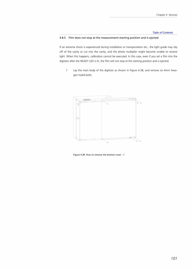
Chapter 4 Services
101
4.8.5 Film does not stop at the measurement starting position and is ejected
If an extreme shock is experienced during installation or transportation etc., the light guide may slip
off of the cavity or cut into the cavity, and the photo multiplier might become unable to receive
light. When this happens, calibration cannot be executed. In this case, even if you set a film into the
digitizer after the READY LED is lit, the film will not stop at the starting position and is ejected.
1 Lay the main body of the digitizer as shown in Figure 4.38, and remove six 4mm hexa-
gon holed bolts.
Figure 4.38 How to remove the bottom cover - 1

Chapter 4 Services
102
2 Remove the bottom cover as shown in Figure 4.39.
Figure 4.39 How to remove the bottom cover - 2
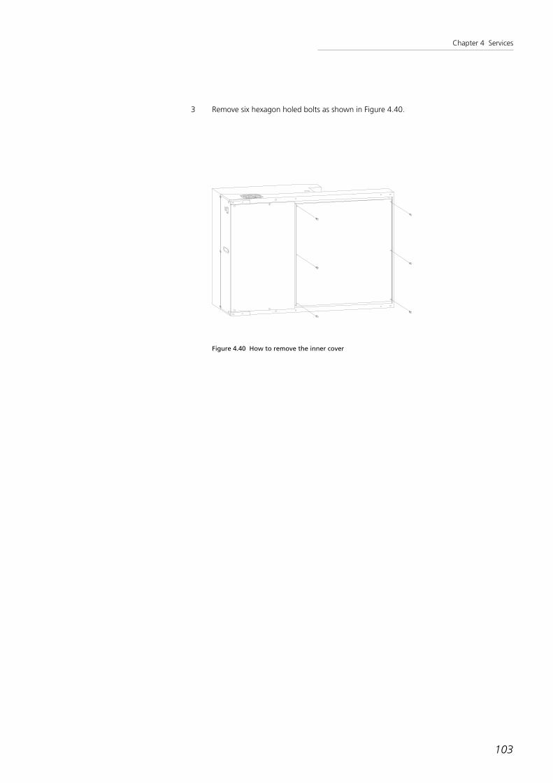
Chapter 4 Services
103
3 Remove six hexagon holed bolts as shown in Figure 4.40.
Figure 4.40 How to remove the inner cover

Chapter 4 Services
104
4 Remove the inner cover and uncover the photometry part as shown in Figure 4.41.
Figure 4.41 Photometry part - inside
Cavity
Light guide securing screw
Light guide securing screw
Light guide
Photo multipliers

Chapter 4 Services
105
5 Confirm the positions of the cavity and the light guide as shown in Figure 4.42. Figure
4.43 is an enlarged view of the proper positions of these two components.
Figure 4.42 Position of cavity and light guide

Chapter 4 Services
106
Cavity Light guide
Seen from the left side
Light guide
Cavity
Figure 4.43 The proper state - light guide inside the cavity

Chapter 4 Services
107
6 In Figure 4.44, the light guide is too deep inside the cavity. In this case, loosen the hexa-
gon holed bolts (light guide securing screw) shown in Figure 4.41 and adjust the position
of the light guide.
Cavity Light guide
Seen from the left side
Light guide
Cavity
Figure 4.44 Light guide is too deep inside the cavity

Chapter 4 Services
108
7 In Figure 4.45, the light guide is about to come off of the cavity. In this case also, loosen
the hexagon holed bolts (light guide securing screw) shown in Figure 4.41 and adjust the
position of the light guide.
Cavity Light guide
Seen from the left side
Light guide
Cavity
Figure 4.45 Light guide is about to come off the cavity

Chapter 4 Services
109
4.8.6 Film is not ejected
Because the transportation mechanism of the digitizer uses roller transportation, a slight curl in the
film may result in the film coming off the roller at the optical density measurement section. If this
happens, film transport is impossible.
Press the EJECT button for a few seconds to reverse the transportation roller. See if this ejects the
film. If this does not work:
If you can see the jammed film, see Section 4.4.1, "Removing the top plate" to remove the top plate
and remove the film.
If you cannot see the film, see Section 4.4.7 "Cleaning film jams" to remove the film.
4.8.7 Film size is not correctly detected
As explained in Section 4.3.3, "Detection of film size", the horizontal size of the film is detected by
scanning the film, and the vertical size is detected by Sensors 1 and 2.
Film size detection errors are mostly caused by failures of Sensors 1 or 2.
Check the movement of the sensor according to Section 4.4.8, "Checking the sensor movement".
4.8.8 The entire image looks black
This digitizer is designed to automatically execute calibration and adjust the high voltage sent to the
photo multipliers before measuring the film.
The possibility is that calibration operation is not completed properly.
Check the calibration operation according to Section 3.9, "Confirming the optical system".
4.8.9 An irregular diagonal line not in the original film is seen in the scanned image.
You may see irregular diagonal patterns in the scanned image displayed on the monitor. This is
called a "moire". If there is a grid in the film, the moire may occur between the grid and the digitiz-
er. If you are displaying the images in a pixel-skipping mode, the moire may occur between the digi-
tizer and the display. When scanning a film with a grid, set the scan mode to high resolution and
reduce the pixel spacing to minimize the moire.

Chapter 4 Services
110
4.8.10 A stripe is displayed at a right angle from the horizontal scan
If dust drops inside the cavity on the place where the calibration data is affected, the dust is dis-
played as a white line in the image.
Follow the procedure in Section 4.4.10 "Cleaning the light correction cavity" to clean the cavity and
remove the dust.
4.8.11 The O.D. value of the image sandwiched between two transparent sheets is incorrect
When a small step tablet for use in optical density meters is placed between a transparent sheet and
scanned, the optical density value of the image might be lower than the standard value. This hap-
pens as a result of when a small and high-O.D. material is scanned, the light reflected on the materi-
al or the light on the lens flare leak out from the photometry unit.
If you need to scan a small and high-O.D. material, prepare a 14-inch wide black film, make a slightly
smaller cutout, and attach the material there to cone out the extraneous light and measure high
O.D. accurately.

111
Chapter 5
Confirming basic operations

Chapter 5 Confirming basic operations
To check the basic operation of the digitizer, connect the digitizer with the PC for testing, and run
the attached software and the Oscillo tool. The following explanation assumes this software is
already installed on the test PC.
The basic operation is checked first, followed by the calibration test and the film size detection test.
The content of Section 5.1, "Checking the basic operation" is the same as Section 3.8.
112

Chapter 5 Confirming basic operations
5.1 Checking the basic operation
1 Start the application software
Start the application software.
(See the User's Guide of the application software.)
2 Set a film
Set a film in the digitizer. The digitizer first draws the film inside, pushes it back to the starting posi-
tion of film measurement, and then waits for a film read command from the PC. At this point, the
digitizer's READY LED is turned off.
3 Check the EJECT operation
Press the EJECT button in the upper part of the digitizer. The transportation mechanism begins the
film feed operation. If the EJECT button is pressed during this operation, the film feed operation
stops. Pressing the button again resumes the operation.
Check that the film is transported smoothly and no unusual noise is heard during the transportation
mechanism.
4 Film read command is issued
On your PC's screen, click the "Scan" button of the application software. The digitizer begins the
film read operation.
When complete, the film is ejected from the outlet. At this point, the READY LED turns on.
5 The measurement result is displayed
The image read by the digitizer is displayed on the PC.
The software automatically adjusts the image to display the entire image on the screen.
6 Assess the image
If the image is correctly displayed, the digitizer's operation can be judged as OK.
113

Chapter 5 Confirming basic operations
5.2 Calibration check
Double-click the file "Oscillo.exe" in the "Oscillo" folder to start the Oscillo tool.
5.2.1 Confirmation of state of digitizers
1 Ready status
The digitizer's ready status is displayed in the main window's Ready group box (Figure 5.1).
If four check boxes are checked, the digitizer is ready.
114
Figure 5.1 Ready group box
2 Current status
The number of revolutions of the digitizer's polygons, the HV value, the AD value, and the current
film size in the digitizer are displayed in the Current Status group box (Figure 5.2).
Figure 5.2 Current Status group box
3 Sensor status
The sensor status is displayed in the Switch group box (Figure 5.3).
Figure 5.3 Switch group box

Chapter 5 Confirming basic operations
5.2.2 Calibration
1 Calibration
Set Pitch, Density, and Scan Mode in the Calibration group box (Figure 5.4) in the main window and
click the "Calibration" button to start calibration.
115
Figure 5.4 Calibration group box
2 Graphical representation of calibration data
Click the "Read" button in the Calibration group box (Figure 5.4) to display the calibration test data
as a graph (Figure 5.5).
Calibration data displayed as a graph
Figure 5.5 The calibration test data graph

Chapter 5 Confirming basic operations
When the value of combo box "Y-Max" or "Y-Min" in the scale group box (Figure 5.6) on the bot-
tom of the graph is changed, the scale of Y axis is changed. Similarly, when the value of "X-Max" or
"X-Min" is changed, the scale of X axis is changed.
116
Figure 5.6 Scale group box for the calibration graph
When the graph's curve is moderate as in Figure 5.5, calibration is OK.
If the graph's curve looks like Figure 5.7, dust is in the cavity. In this case, clean up inside the cavity
with a compressed air spray, etc.
If the graph's curve looks like Figure 5.8, optical axis is out of alignment. In this case, adjust the mir-
ror (See Section 4.5.2, "Adjusting the mirror angle").
Figure 5.7 Abnormal waveform 1 - Dust in cavity

Chapter 5 Confirming basic operations
117
Figure 5.8 Abnormal waveform 2 - Optical axis out of alignment
3 Repeated calibration / graphical representation
Click the "Rep." button in the Calibration group box (Figure 5.4) to repeat calibration and graphical
representation infinitely. The "Rep." button changes to the "StopRep." button.
Click the "Hold" checkbox in the graph's scale group box (Figure 5.6) to superimpose the new data
on the previous graph (Figure 5.9).
Click the "StopRep." button to stop repeated calibration.
Figure 5.9 Superimpose the new calibration data on the old

Chapter 5 Confirming basic operations
4 Clear calibration data
Click the "Calibration Data Clear" button on the bottom right of the main window to clear the cali-
bration data on memory.
5.2.3 Line Scan
1 Line scan and its graphical representation
Click the "Scan Line" button on the "Line Scan" group box (Figure 5.10) to scan one line and display
the scanned data as a graph (Figure 5.11).
118
Figure 5.10 Line Scan group box
Click the "Calibration" checkbox to perform calibration before scan.
Click the "Move" checkbox to move the film during scan.

Chapter 5 Confirming basic operations
When the value of combo box "Y-Max" or "Y-Min" in the scale group box (Figure 5.6) on the bot-
tom of the graph is changed, the scale of Y axis is changed. Similarly, when the value of "X-Max" or
"X-Min" is changed, the scale of X axis is changed.
119
Figure 5.11 Graphical representation of scan data

Chapter 5 Confirming basic operations
2 Repeated scan and its graphical representation.
Click the "Oscillo" button in the "Line Scan" group box (Figure 5.10) to repeat one-line scan and
graphical representation infinitely. At this point, the "Oscillo" button changes into the "StopOscillo"
button.
Click the "Hold" checkbox in the graph's scale group box (Figure 5.6) to superimpose the new data
on the previous graph Click the "StopOscillo" button to stop repeated scan.
120
Figure 5.12 Superimpose the new scan data on the old

Chapter 5 Confirming basic operations
5.3 Film size detection test
Test with films of all desired sizes to confirm the film sizes and the direction are correctly detected.
The tests are performed with the Oscillo tool.
The film sizes detectable by this digitizer are as follows:
121
17 inch *14 inch (Portrait)
14 inch *14 inch
14 inch *11 inch (Portrait, Landscape)
12 inch * 10 inch (Portrait, Landscape)
10 inch * 8 inch (Portrait, Landscape)
5 inch * 12-inch (Portrait)
B4 (Portrait, Landscape)
18cm*43cm(Portrait)
30cm*40cm (Portrait)
20cm*40cm (Portrait)
15cm*40cm (Portrait)
30cm*35cm (Portrait, Landscape)
30cm*30cm
24cm*30cm (Portrait)
15cm*30cm (Portrait, Landscape)
24cm*24cm
18cm*24cm (Portrait)

Chapter 5 Confirming basic operations
1 Start the Oscillo tool
Start the Oscillo tool.
(See Section 3.9, "Confirming the optical system".)
2 Set film
Set film in the digitizer.
3 Assess the Image
If the length and breadth of the film set in the digitizer is correctly displayed in the Film Size column
of the Current Status group box (Figure 5.13) in the main window, the film size detection is judged
as OK.
Perform this operation for all desired film sizes.
122
Figure 5.13 The Current Status group box
The film size is displayed.

123
Chapter 6
Installation quality check sheet

Chapter 6 Installation quality check sheet
Device Model : 2905
Customer Name :
Serial Number :
Company/Office in Charge of Service :
Date of Installation Completed (Month/Day/Year) :
Person in Charge of Installation :
Notes :
No.
Item
Criteria
Result
6.1 The number of accessories
(1) Floppy disk for testing [ ]
(2) Power cable [ ]
(3) 2905 User's Guide
(4) User's Guide for the application software [ ]
6.2 The digitizer's power supply
POWER LED is on [ ]
READY LED is on [ ]
124

Chapter 6 Installation quality check sheet
6.3 Basic operation
(1) Film set operation
READY LED is off [ ]
(2) Film eject operation
Press the EJECT button - film is ejected [ ]
Press the EJECT button during film ejection - ejection stops [ ]
Press the EJECT button again - ejection resumes [ ]
(3) Film read operation
Film read operation is performed [ ]
No noise from the transportation mechanism [ ]
READY LED goes off after film ejection [ ]
(4) Result of film read
The image displayed on the PC is OK [ ]
The image is not tilted (the horizontal scan direction is OK) [ ]
Film size is OK [ ]
No scratch on film [ ]
125

Chapter 6 Installation quality check sheet
6.4 Film size detection test
Mark the film sizes actually tested from the list below.
(The value is stated as "height * width".)
(1) 17 x 14 inch [ ]
(2) 14 x 14 inch [ ]
(3) 14 x 11 inch [ ]
(4) 11 x 14 inch [ ]
(5) 12 x 10 inch [ ]
(6) 10 x 12 inch [ ]
(7) 10 x 8 inch [ ]
(8) 8 x 10 inch [ ]
(9) 5 x 12 inch [ ]
(10) B4 Portrait [ ]
(11) B4 Landscape [ ]
(12) 18 x 43 cm [ ]
(13) 30 x 40 cm [ ]
(14) 20 x 40 cm [ ]
(15) 15 x 40 cm [ ]
(16) 30 x 35 cm [ ]
(17) 35 x 30 cm [ ]
(18) 30 x 30 cm [ ]
(19) 30 x 24 cm [ ]
(20) 24 x 30 cm [ ]
(21) 15 x 30 cm [ ]
(22) 24 x 24 cm [ ]
(23) 28 x 24 cm [ ]
126

127
Chapter 7
Maintenance manual

Chapter 7 Maintenance manual
7.1 Start-of-day and end-of-day checks
Start-of-day check
1 Check the cables (power cable, connection cable to the PC) are not damaged.
End-of-day check
1 Check all power is off.
7.2 Regular check
Once a year, clean the cavity by the procedure explained in Section 4.4.10.
If streaks appear on scanned images, wipe Mirror 3 and 4 on Figure 4.20 and the mirror on Figure
4.10 with an alcohol-soaked gauze / cotton bud. Do not apply excessive pressure to the mirrors.
128

129
Appendix
Wiring diagram

Appendix Wiring diagram
130
SEL
EC
T S
WIT
CH

Appendix Wiring diagram
131

Appendix Wiring diagram
132

Appendix Wiring diagram
133