Embed Size (px)
Citation preview
Digitizer
PCA2000 V2.5 1/33 User’s manual
12. Digitizer
12.1 Introduction
The Digitizer module is a tool that has been developed to: 1. Use quickly and efficiently all the information contained in a 3 views drawing.
- To measure distances - To measure distance ratios - To measure angles - To measure surfaces
2. Digitize quickly a curve that will have been scanned previously such as the polar of a glider for example.
Table 1 : Use a 3 views drawing or Digitalize a curve
Digitizer
PCA2000 V2.5 2/33 User’s manual
12.2 Table of content
12. DIGITIZER.................................................................................................................... 1 12.1 Introduction...................................................................................................................1 12.2 Table of content............................................................................................................ 2 12.3 Description ................................................................................................................... 3 12.4 To load an image.......................................................................................................... 5 12.5 To georeference an image ........................................................................................... 6 12.5.1 Introduction............................................................................................................... 6 12.5.2 Determine the image attributes (1/5)........................................................................ 8 12.5.3 To localize the first reference point on the X axis (2/5) .......................................... 10 12.5.4 To localize the second reference point on the X axis (3/5) .................................... 12 12.5.5 To localize the first reference point on the Y axis (4/5) .......................................... 13 12.5.6 To localize the second reference point on the Y axis (5/5) .................................... 14 12.6 To save a georeferenced image................................................................................. 15 12.7 To open a georeferenced file ..................................................................................... 16 12.8 To use the information contained in a 3 views plan ................................................... 18 12.8.1 Introduction............................................................................................................. 18 12.8.2 To measure a distance........................................................................................... 20 12.8.3 Calculation of a distance ratio ................................................................................ 21 12.8.4 Measure of an angle............................................................................................... 22 12.8.5 Measure of a surface.............................................................................................. 23 12.8.6 To add an area to the current selection.................................................................. 28 12.8.7 To withdraw an area from the current selection ..................................................... 29 12.9 To digitalize a curve ................................................................................................... 30 12.9.1 Introduction............................................................................................................. 30 12.9.2 To digitalize a curve ............................................................................................... 31 12.9.3 Validation of the selection ...................................................................................... 32 12.9.4 Management of the selection ................................................................................. 33
Digitizer
PCA2000 V2.5 3/33 User’s manual
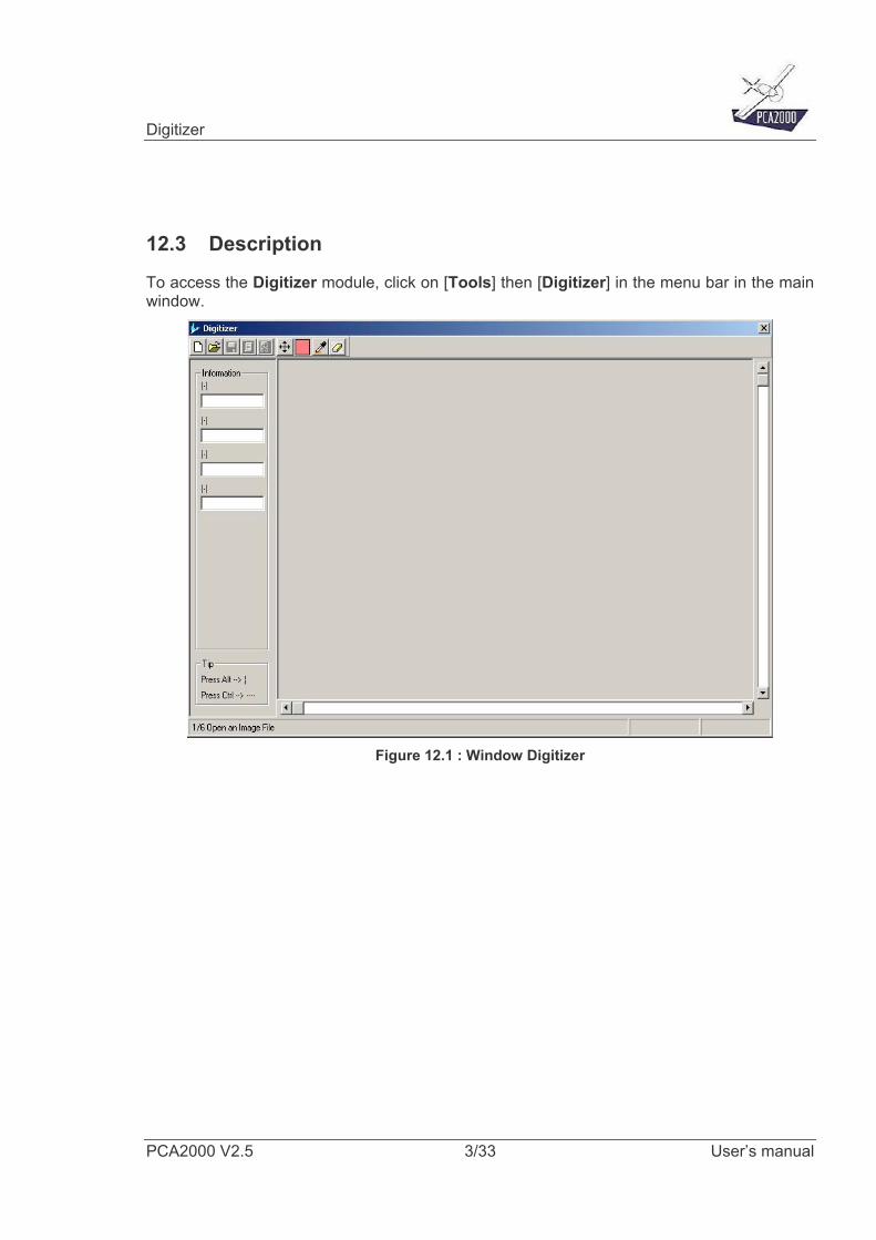
12.3 Description
To access the Digitizer module, click on [Tools] then [Digitizer] in the menu bar in the main window.
Figure 12.1 : Window Digitizer
Digitizer
PCA2000 V2.5 4/33 User’s manual
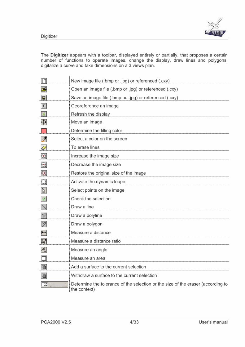
The Digitizer appears with a toolbar, displayed entirely or partially, that proposes a certain number of functions to operate images, change the display, draw lines and polygons, digitalize a curve and take dimensions on a 3 views plan.
New image file (.bmp or .jpg) or referenced (.cxy)
Open an image file (.bmp or .jpg) or referenced (.cxy)
Save an image file (.bmp ou .jpg) or referenced (.cxy)
Georeference an image
Refresh the display
Move an image
Determine the filling color
Select a color on the screen
To erase lines
Increase the image size
Decrease the image size
Restore the original size of the image
Activate the dynamic loupe
Select points on the image
Check the selection
Draw a line
Draw a polyline
Draw a polygon
Measure a distance
Measure a distance ratio
Measure an angle
Measure an area
Add a surface to the current selection
Withdraw a surface to the current selection
Determine the tolerance of the selection or the size of the eraser (according to the context)
Digitizer
PCA2000 V2.5 5/33 User’s manual
12.4 To load an image
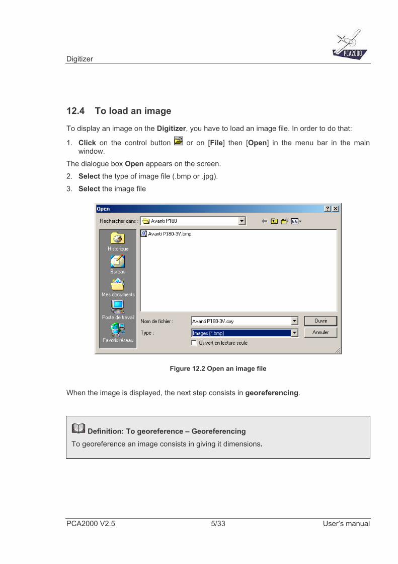
To display an image on the Digitizer, you have to load an image file. In order to do that:
1. Click on the control button or on [File] then [Open] in the menu bar in the main window.
The dialogue box Open appears on the screen. 2. Select the type of image file (.bmp or .jpg). 3. Select the image file
Figure 12.2 Open an image file
When the image is displayed, the next step consists in georeferencing.
Definition: To georeference – Georeferencing To georeference an image consists in giving it dimensions.
Digitizer
PCA2000 V2.5 6/33 User’s manual
12.5 To georeference an image
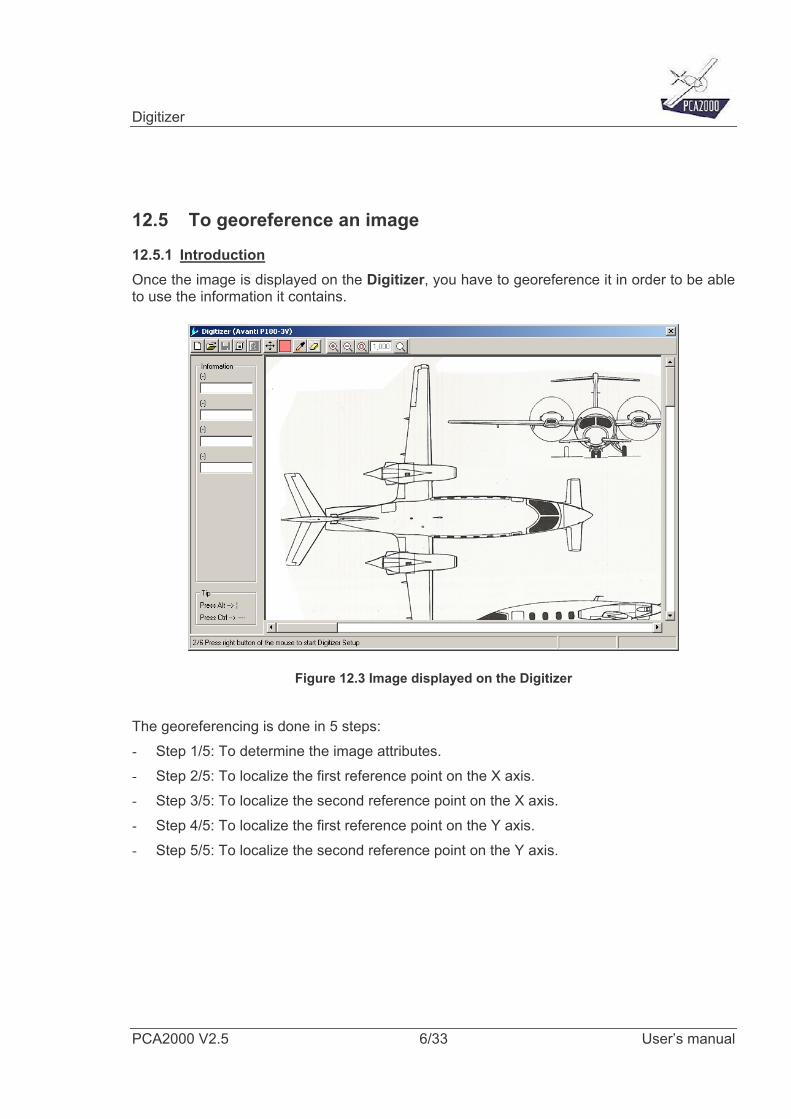
12.5.1 Introduction Once the image is displayed on the Digitizer, you have to georeference it in order to be able to use the information it contains.
Figure 12.3 Image displayed on the Digitizer
The georeferencing is done in 5 steps: - Step 1/5: To determine the image attributes. - Step 2/5: To localize the first reference point on the X axis. - Step 3/5: To localize the second reference point on the X axis. - Step 4/5: To localize the first reference point on the Y axis. - Step 5/5: To localize the second reference point on the Y axis.
Digitizer
PCA2000 V2.5 7/33 User’s manual
When initializing the image, follow the instructions that appear in the status bar in theDigitizer window.
It is not unusual to take the horizontal axis as X axis as well as the vertical axis as Y axis The X axis can be oblique (bent compared to the horizontal one) The Y axis can be oblique (bent compared to the vertical one)
It is possible that the X and Y axis are not orthogonal
Digitizer
PCA2000 V2.5 8/33 User’s manual
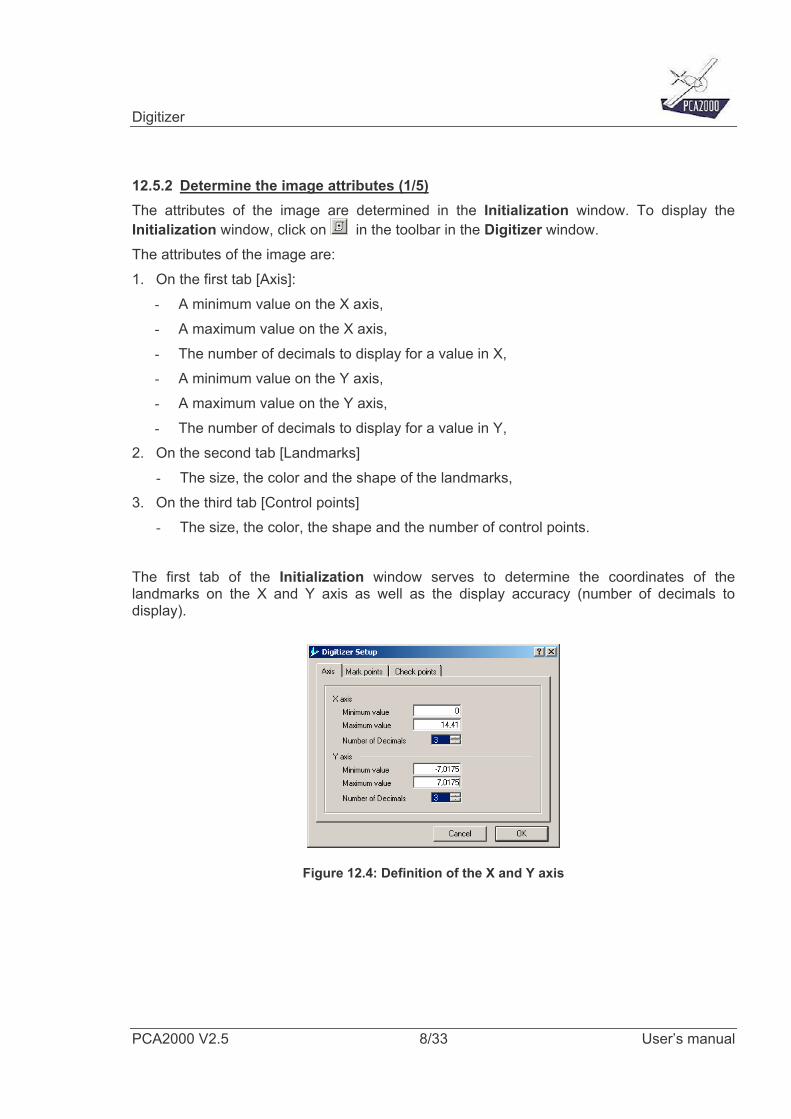
12.5.2 Determine the image attributes (1/5) The attributes of the image are determined in the Initialization window. To display the Initialization window, click on in the toolbar in the Digitizer window. The attributes of the image are: 1. On the first tab [Axis]:
- A minimum value on the X axis, - A maximum value on the X axis, - The number of decimals to display for a value in X, - A minimum value on the Y axis, - A maximum value on the Y axis, - The number of decimals to display for a value in Y,
2. On the second tab [Landmarks] - The size, the color and the shape of the landmarks,
3. On the third tab [Control points] - The size, the color, the shape and the number of control points.
The first tab of the Initialization window serves to determine the coordinates of the landmarks on the X and Y axis as well as the display accuracy (number of decimals to display).
Figure 12.4: Definition of the X and Y axis
Digitizer
PCA2000 V2.5 9/33 User’s manual
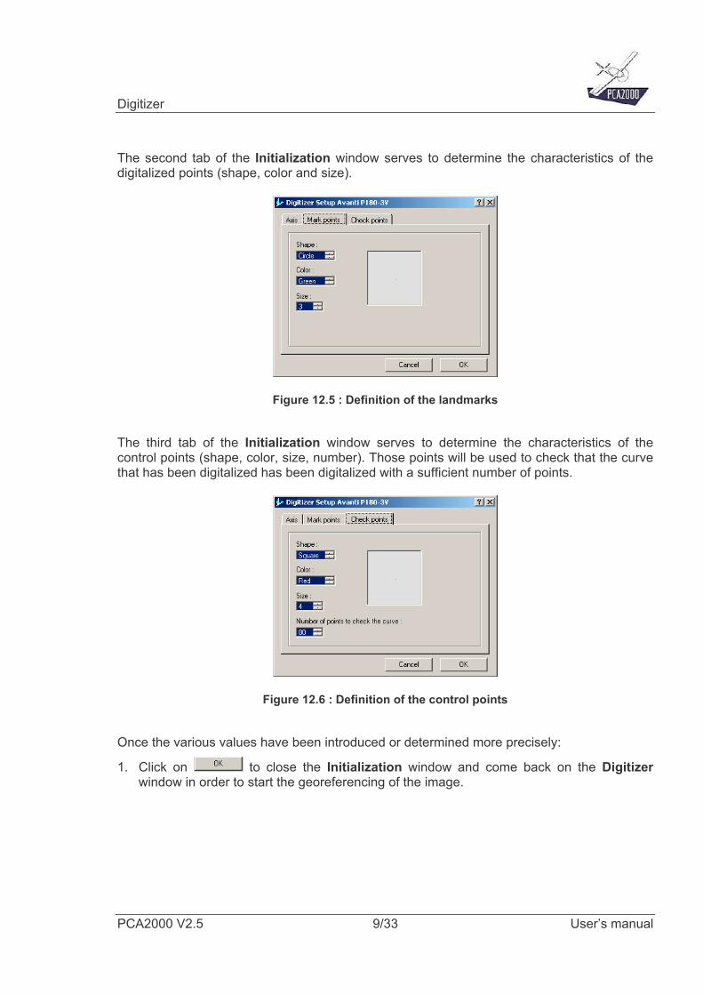
The second tab of the Initialization window serves to determine the characteristics of the digitalized points (shape, color and size).
Figure 12.5 : Definition of the landmarks
The third tab of the Initialization window serves to determine the characteristics of the control points (shape, color, size, number). Those points will be used to check that the curve that has been digitalized has been digitalized with a sufficient number of points.
Figure 12.6 : Definition of the control points
Once the various values have been introduced or determined more precisely:
1. Click on to close the Initialization window and come back on the Digitizer window in order to start the georeferencing of the image.
Digitizer
PCA2000 V2.5 10/33 User’s manual
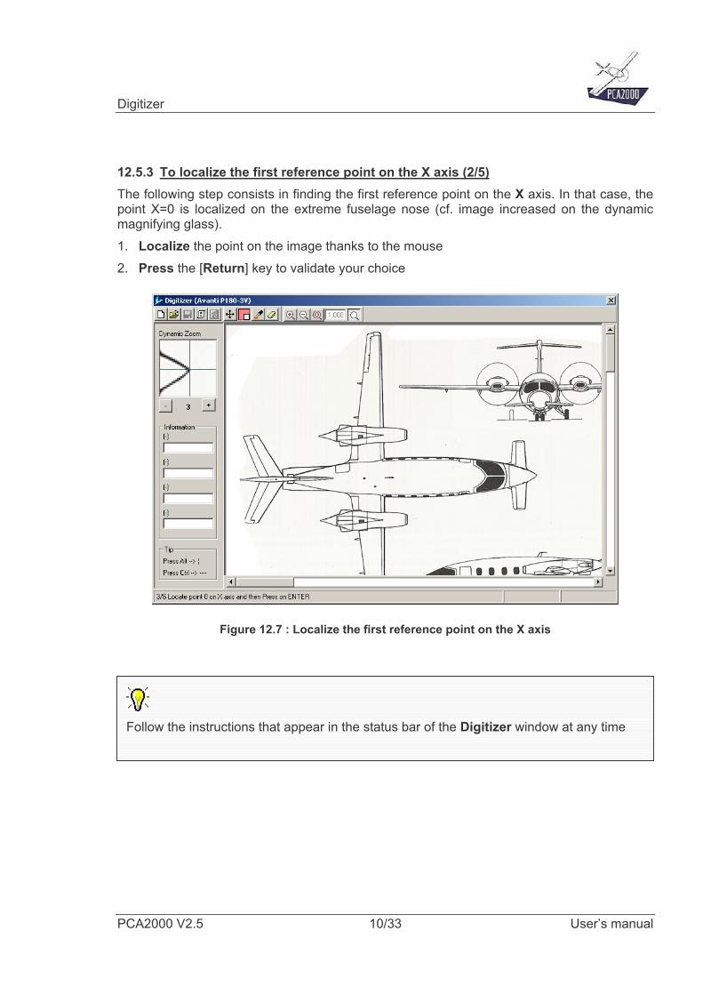
12.5.3 To localize the first reference point on the X axis (2/5) The following step consists in finding the first reference point on the X axis. In that case, the point X=0 is localized on the extreme fuselage nose (cf. image increased on the dynamic magnifying glass). 1. Localize the point on the image thanks to the mouse 2. Press the [Return] key to validate your choice
Figure 12.7 : Localize the first reference point on the X axis
Follow the instructions that appear in the status bar of the Digitizer window at any time
Digitizer
PCA2000 V2.5 11/33 User’s manual
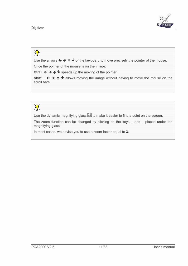
Use the arrows of the keyboard to move precisely the pointer of the mouse. Once the pointer of the mouse is on the image: Ctrl + speeds up the moving of the pointer. Shift + allows moving the image without having to move the mouse on thescroll bars.
Use the dynamic magnifying glass to make it easier to find a point on the screen.
The zoom function can be changed by clicking on the keys + and − placed under themagnifying glass.
In most cases, we advise you to use a zoom factor equal to 3.
Digitizer
PCA2000 V2.5 12/33 User’s manual
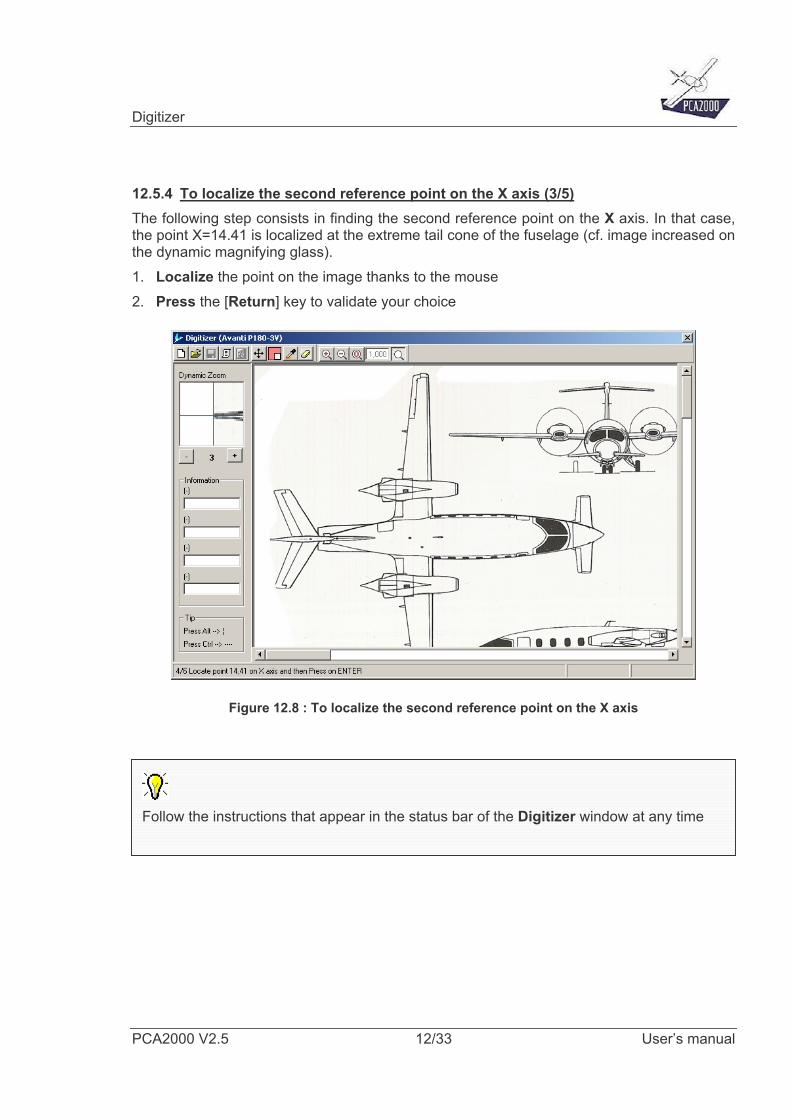
12.5.4 To localize the second reference point on the X axis (3/5) The following step consists in finding the second reference point on the X axis. In that case, the point X=14.41 is localized at the extreme tail cone of the fuselage (cf. image increased on the dynamic magnifying glass). 1. Localize the point on the image thanks to the mouse 2. Press the [Return] key to validate your choice
Figure 12.8 : To localize the second reference point on the X axis
Follow the instructions that appear in the status bar of the Digitizer window at any time
Digitizer
PCA2000 V2.5 13/33 User’s manual
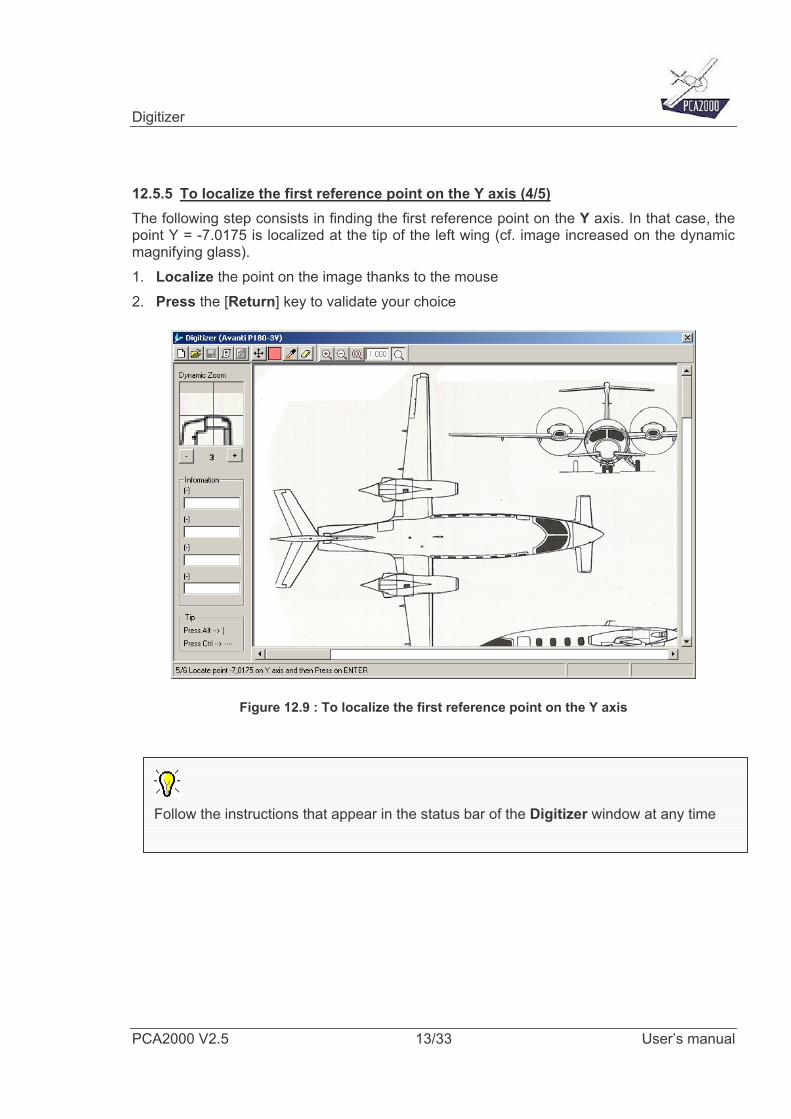
12.5.5 To localize the first reference point on the Y axis (4/5) The following step consists in finding the first reference point on the Y axis. In that case, the point Y = -7.0175 is localized at the tip of the left wing (cf. image increased on the dynamic magnifying glass). 1. Localize the point on the image thanks to the mouse 2. Press the [Return] key to validate your choice
Figure 12.9 : To localize the first reference point on the Y axis
Follow the instructions that appear in the status bar of the Digitizer window at any time
Digitizer
PCA2000 V2.5 14/33 User’s manual
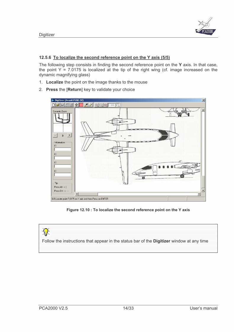
12.5.6 To localize the second reference point on the Y axis (5/5) The following step consists in finding the second reference point on the Y axis. In that case, the point Y = 7.0175 is localized at the tip of the right wing (cf. image increased on the dynamic magnifying glass) 1. Localize the point on the image thanks to the mouse 2. Press the [Return] key to validate your choice
Figure 12.10 : To localize the second reference point on the Y axis
Follow the instructions that appear in the status bar of the Digitizer window at any time
Digitizer
PCA2000 V2.5 15/33 User’s manual
12.6 To save a georeferenced image
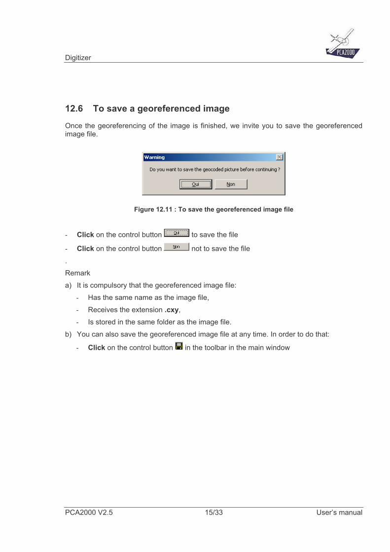
Once the georeferencing of the image is finished, we invite you to save the georeferenced image file.
Figure 12.11 : To save the georeferenced image file
- Click on the control button to save the file
- Click on the control button not to save the file . Remark a) It is compulsory that the georeferenced image file:
- Has the same name as the image file, - Receives the extension .cxy, - Is stored in the same folder as the image file.
b) You can also save the georeferenced image file at any time. In order to do that:
- Click on the control button in the toolbar in the main window
Digitizer
PCA2000 V2.5 16/33 User’s manual
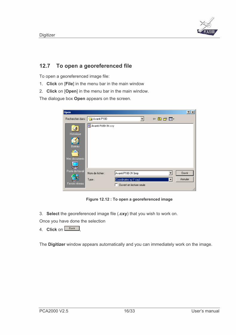
12.7 To open a georeferenced file
To open a georeferenced image file: 1. Click on [File] in the menu bar in the main window 2. Click on [Open] in the menu bar in the main window. The dialogue box Open appears on the screen.
Figure 12.12 : To open a georeferenced image
3. Select the georeferenced image file (.cxy) that you wish to work on. Once you have done the selection
4. Click on , The Digitizer window appears automatically and you can immediately work on the image.
Digitizer
PCA2000 V2.5 17/33 User’s manual
A compulsory validation In order to check the quality of the image as well as the good progress of thegeoreferencing, we strongly advise you to proceed with the validation of thegeoreferenced image. The validation consists in comparing the result of a measure (distance or surface) doneon a georeferenced image with known information (wing span or surface in the case of a3 views plan for example).
In the case of a 3 views plan: The first checking consists in measuring the wing span. In order to do that, we invite youto follow the procedure described under 12.8.2 The second checking consists in measuring the wing surface. In order to do that, we inviteyou to follow the procedure described under 12.8.5. A difference of ±3% remainsacceptable. In the case of a graphic: The checking consists in placing the cursor on different points of known coordinates (theorigin of the graph for example, one or more points on the main axis, …) and checkingthat the coordinates sent back by the cursor that are displayed in the upper right corner ofthe Digitizer correspond to each other.
Digitizer
PCA2000 V2.5 18/33 User’s manual
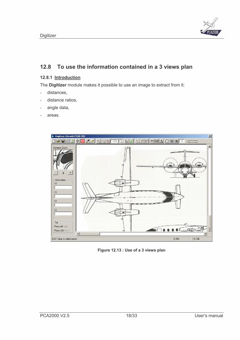
12.8 To use the information contained in a 3 views plan
12.8.1 Introduction The Digitizer module makes it possible to use an image to extract from it: - distances, - distance ratios, - angle data, - areas.
Figure 12.13 : Use of a 3 views plan
Digitizer
PCA2000 V2.5 19/33 User’s manual
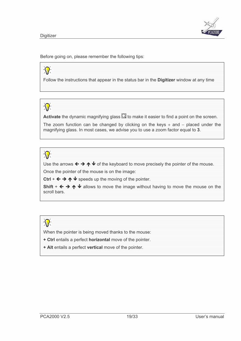
Before going on, please remember the following tips:
Follow the instructions that appear in the status bar in the Digitizer window at any time
Use the arrows of the keyboard to move precisely the pointer of the mouse. Once the pointer of the mouse is on the image: Ctrl + speeds up the moving of the pointer. Shift + allows to move the image without having to move the mouse on thescroll bars.
Activate the dynamic magnifying glass to make it easier to find a point on the screen.
The zoom function can be changed by clicking on the keys + and − placed under themagnifying glass. In most cases, we advise you to use a zoom factor equal to 3.
When the pointer is being moved thanks to the mouse: + Ctrl entails a perfect horizontal move of the pointer.
+ Alt entails a perfect vertical move of the pointer.
Digitizer
PCA2000 V2.5 20/33 User’s manual
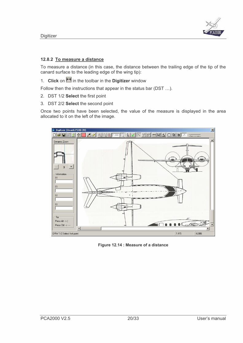
12.8.2 To measure a distance To measure a distance (in this case, the distance between the trailing edge of the tip of the canard surface to the leading edge of the wing tip):
1. Click on in the toolbar in the Digitizer window Follow then the instructions that appear in the status bar (DST …). 2. DST 1/2 Select the first point 3. DST 2/2 Select the second point Once two points have been selected, the value of the measure is displayed in the area allocated to it on the left of the image.
Figure 12.14 : Measure of a distance
Digitizer
PCA2000 V2.5 21/33 User’s manual
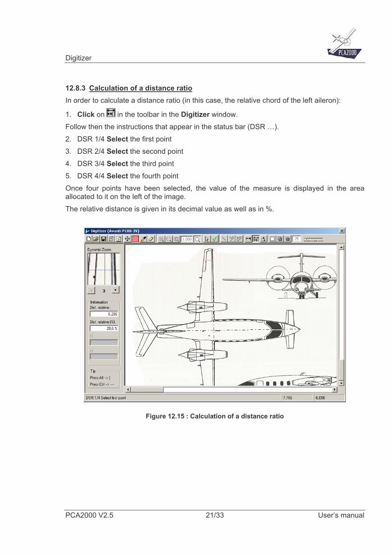
12.8.3 Calculation of a distance ratio In order to calculate a distance ratio (in this case, the relative chord of the left aileron):
1. Click on in the toolbar in the Digitizer window. Follow then the instructions that appear in the status bar (DSR …). 2. DSR 1/4 Select the first point 3. DSR 2/4 Select the second point 4. DSR 3/4 Select the third point 5. DSR 4/4 Select the fourth point Once four points have been selected, the value of the measure is displayed in the area allocated to it on the left of the image. The relative distance is given in its decimal value as well as in %.
Figure 12.15 : Calculation of a distance ratio
Digitizer
PCA2000 V2.5 22/33 User’s manual
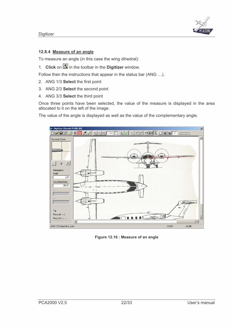
12.8.4 Measure of an angle To measure an angle (in this case the wing dihedral):
1. Click on in the toolbar in the Digitizer window. Follow then the instructions that appear in the status bar (ANG …). 2. ANG 1/3 Select the first point 3. ANG 2/3 Select the second point 4. ANG 3/3 Select the third point Once three points have been selected, the value of the measure is displayed in the area allocated to it on the left of the image. The value of the angle is displayed as well as the value of the complementary angle.
Figure 12.16 : Measure of an angle
Digitizer
PCA2000 V2.5 23/33 User’s manual
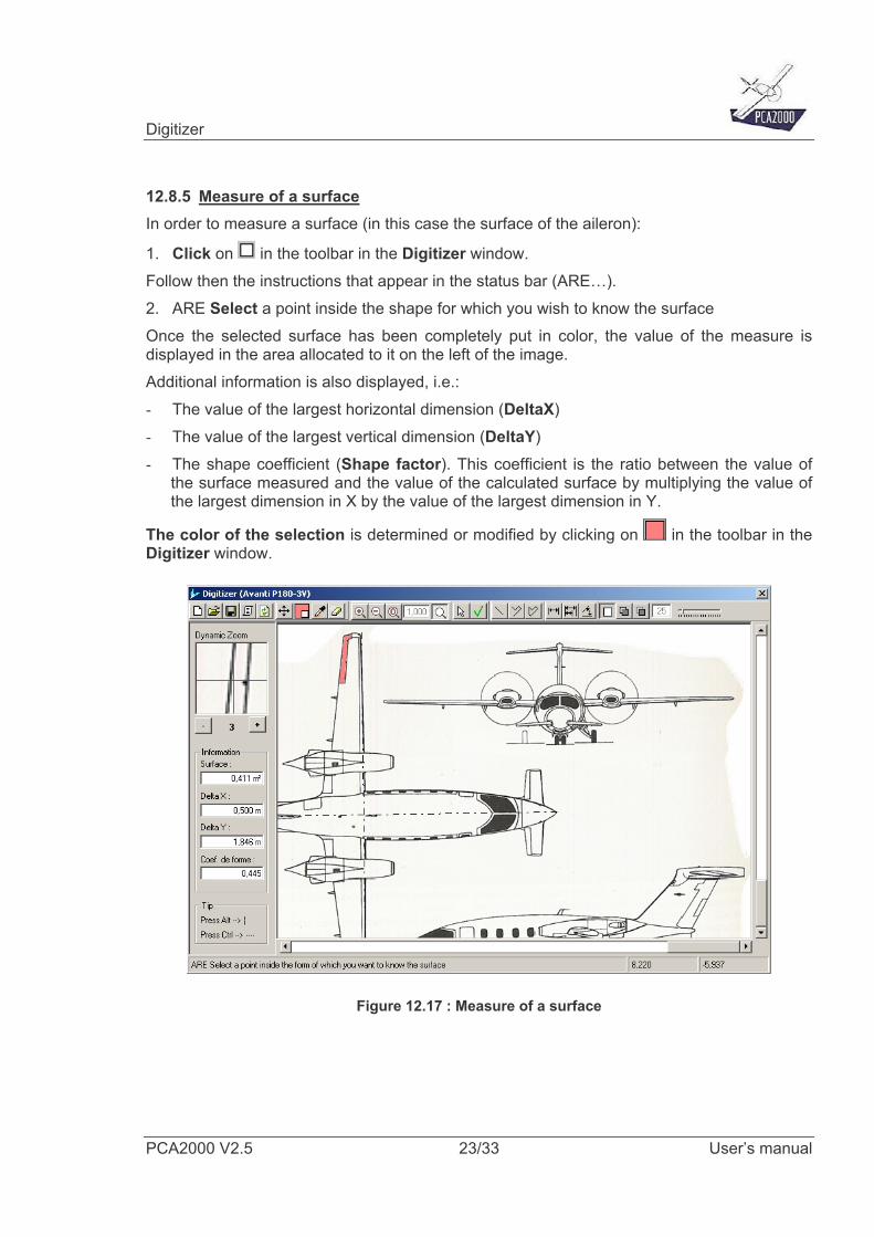
12.8.5 Measure of a surface In order to measure a surface (in this case the surface of the aileron):
1. Click on in the toolbar in the Digitizer window. Follow then the instructions that appear in the status bar (ARE…). 2. ARE Select a point inside the shape for which you wish to know the surface Once the selected surface has been completely put in color, the value of the measure is displayed in the area allocated to it on the left of the image. Additional information is also displayed, i.e.: - The value of the largest horizontal dimension (DeltaX) - The value of the largest vertical dimension (DeltaY) - The shape coefficient (Shape factor). This coefficient is the ratio between the value of
the surface measured and the value of the calculated surface by multiplying the value of the largest dimension in X by the value of the largest dimension in Y.
The color of the selection is determined or modified by clicking on in the toolbar in the Digitizer window.
Figure 12.17 : Measure of a surface
Digitizer
PCA2000 V2.5 24/33 User’s manual
The initial color of the surface is determined by the color of the point that is at the rightof the pointer at the time of the selection. A point is part of a surface if its color corresponds to the one of the surface, except forone tolerance value. By default, this tolerance equals 25.
The tolerance value can be modified by moving the cursor
BEWARE If that tolerance is too high, the edges of the shape risk not to be recognized and theselection will go beyond the selected area. If that happens, running the function can beinterrupted by clicking on the Esc (Escape) key. In the same way, if the selected area is not closed, the selection will go beyond thedesired area. In that case, it is necessary to interrupt the function by clicking on the Esc(Escape) key.
Digitizer
PCA2000 V2.5 25/33 User’s manual
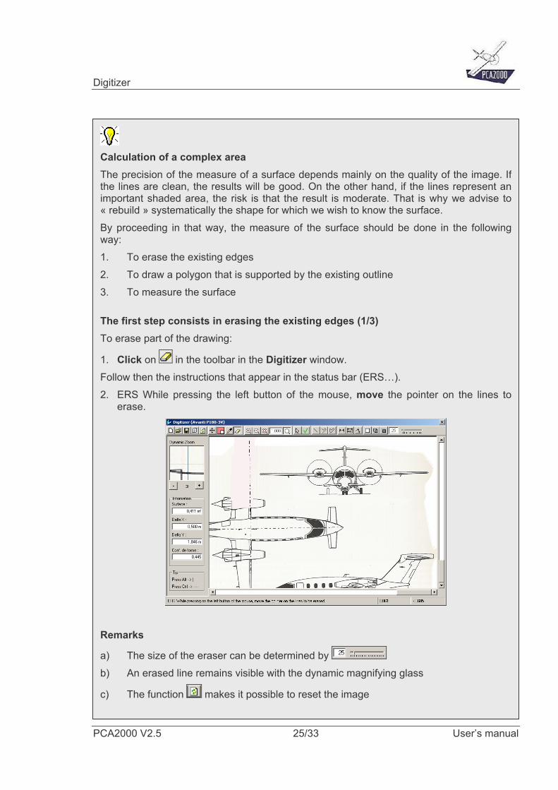
Calculation of a complex area The precision of the measure of a surface depends mainly on the quality of the image. Ifthe lines are clean, the results will be good. On the other hand, if the lines represent animportant shaded area, the risk is that the result is moderate. That is why we advise to« rebuild » systematically the shape for which we wish to know the surface. By proceeding in that way, the measure of the surface should be done in the followingway: 1. To erase the existing edges 2. To draw a polygon that is supported by the existing outline 3. To measure the surface
The first step consists in erasing the existing edges (1/3) To erase part of the drawing:
1. Click on in the toolbar in the Digitizer window. Follow then the instructions that appear in the status bar (ERS…). 2. ERS While pressing the left button of the mouse, move the pointer on the lines to
erase.
Remarks
a) The size of the eraser can be determined by b) An erased line remains visible with the dynamic magnifying glass
c) The function makes it possible to reset the image
Digitizer
PCA2000 V2.5 26/33 User’s manual
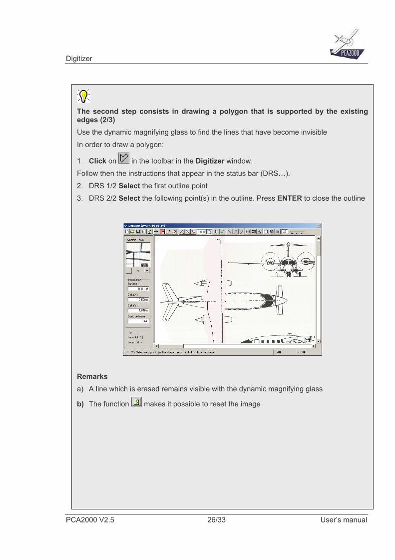
The second step consists in drawing a polygon that is supported by the existingedges (2/3) Use the dynamic magnifying glass to find the lines that have become invisible In order to draw a polygon:
1. Click on in the toolbar in the Digitizer window. Follow then the instructions that appear in the status bar (DRS…). 2. DRS 1/2 Select the first outline point 3. DRS 2/2 Select the following point(s) in the outline. Press ENTER to close the outline
Remarks a) A line which is erased remains visible with the dynamic magnifying glass
b) The function makes it possible to reset the image
Digitizer
PCA2000 V2.5 27/33 User’s manual
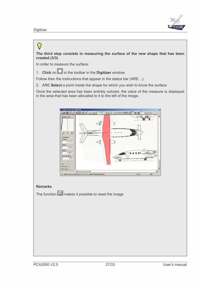
The third step consists in measuring the surface of the new shape that has beencreated (3/3) In order to measure the surface:
1. Click on in the toolbar in the Digitizer window. Follow then the instructions that appear in the status bar (ARE…). 2. ARE Select a point inside the shape for which you wish to know the surface Once the selected area has been entirely colored, the value of the measure is displayedin the area that has been allocated to it to the left of the image.
Remarks
The function makes it possible to reset the image
Digitizer
PCA2000 V2.5 28/33 User’s manual
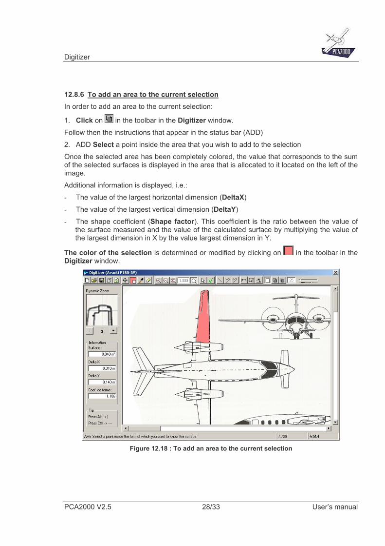
12.8.6 To add an area to the current selection In order to add an area to the current selection:
1. Click on in the toolbar in the Digitizer window. Follow then the instructions that appear in the status bar (ADD) 2. ADD Select a point inside the area that you wish to add to the selection Once the selected area has been completely colored, the value that corresponds to the sum of the selected surfaces is displayed in the area that is allocated to it located on the left of the image. Additional information is displayed, i.e.: - The value of the largest horizontal dimension (DeltaX) - The value of the largest vertical dimension (DeltaY) - The shape coefficient (Shape factor). This coefficient is the ratio between the value of
the surface measured and the value of the calculated surface by multiplying the value of the largest dimension in X by the value largest dimension in Y.
The color of the selection is determined or modified by clicking on in the toolbar in the Digitizer window.
Figure 12.18 : To add an area to the current selection
Digitizer
PCA2000 V2.5 29/33 User’s manual
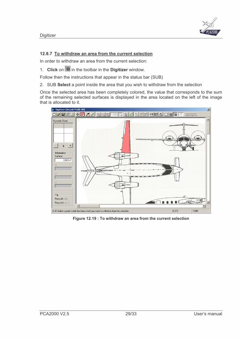
12.8.7 To withdraw an area from the current selection In order to withdraw an area from the current selection:
1. Click on in the toolbar in the Digitizer window. Follow then the instructions that appear in the status bar (SUB) 2. SUB Select a point inside the area that you wish to withdraw from the selection Once the selected area has been completely colored, the value that corresponds to the sum of the remaining selected surfaces is displayed in the area located on the left of the image that is allocated to it.
Figure 12.19 : To withdraw an area from the current selection
Digitizer
PCA2000 V2.5 30/33 User’s manual
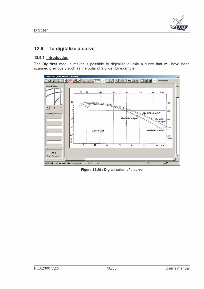
12.9 To digitalize a curve
12.9.1 Introduction The Digitizer module makes it possible to digitalize quickly a curve that will have been scanned previously such as the polar of a glider for example
Figure 12.20 : Digitalization of a curve
Digitizer
PCA2000 V2.5 31/33 User’s manual
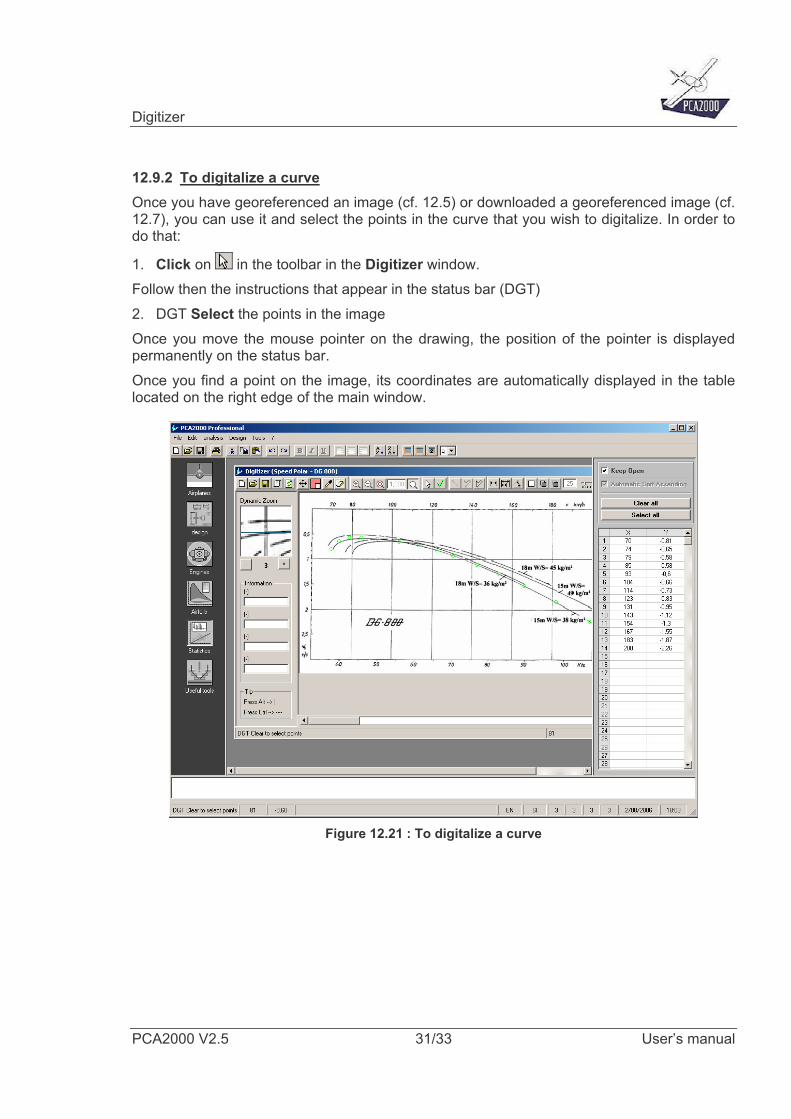
12.9.2 To digitalize a curve Once you have georeferenced an image (cf. 12.5) or downloaded a georeferenced image (cf. 12.7), you can use it and select the points in the curve that you wish to digitalize. In order to do that:
1. Click on in the toolbar in the Digitizer window. Follow then the instructions that appear in the status bar (DGT) 2. DGT Select the points in the image Once you move the mouse pointer on the drawing, the position of the pointer is displayed permanently on the status bar. Once you find a point on the image, its coordinates are automatically displayed in the table located on the right edge of the main window.
Figure 12.21 : To digitalize a curve
Digitizer
PCA2000 V2.5 32/33 User’s manual
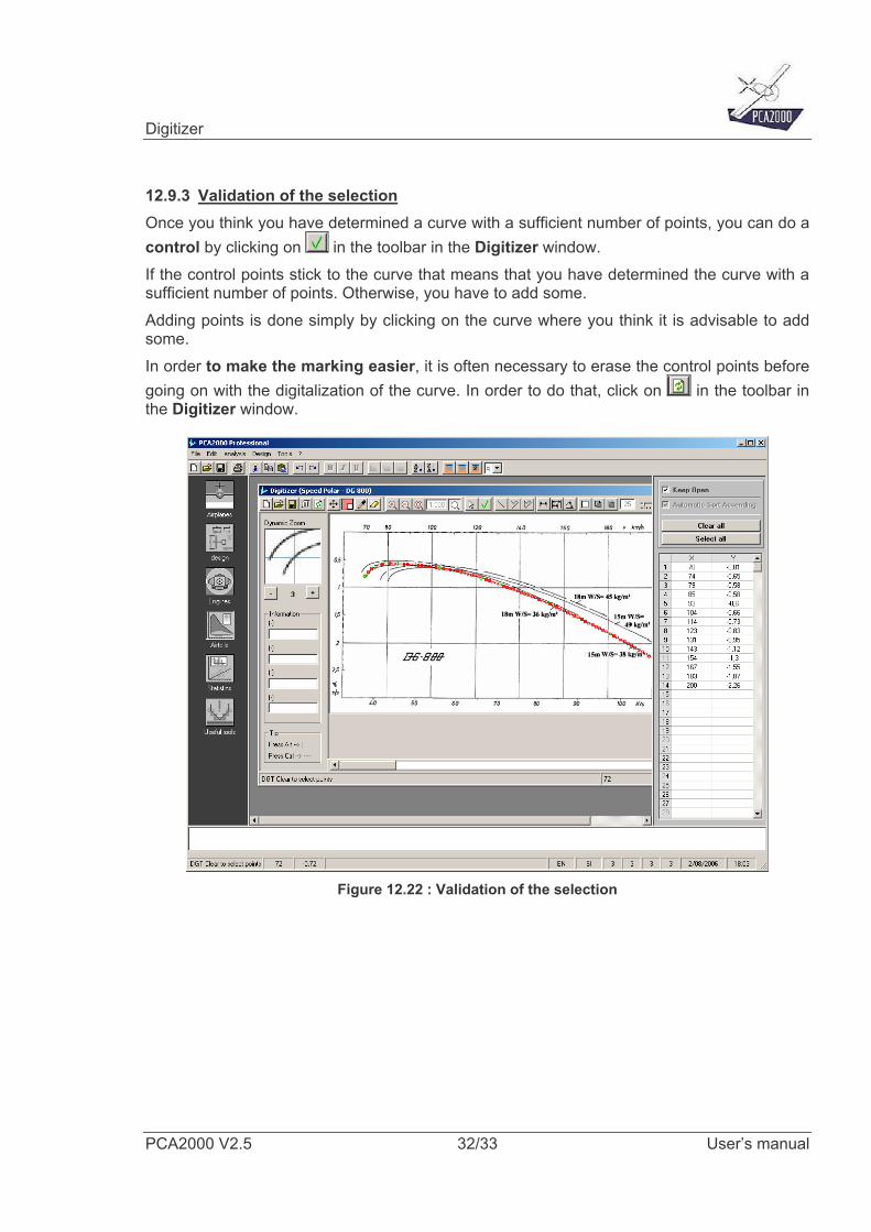
12.9.3 Validation of the selection Once you think you have determined a curve with a sufficient number of points, you can do a control by clicking on in the toolbar in the Digitizer window. If the control points stick to the curve that means that you have determined the curve with a sufficient number of points. Otherwise, you have to add some. Adding points is done simply by clicking on the curve where you think it is advisable to add some. In order to make the marking easier, it is often necessary to erase the control points before going on with the digitalization of the curve. In order to do that, click on in the toolbar in the Digitizer window.
Figure 12.22 : Validation of the selection
Digitizer
PCA2000 V2.5 33/33 User’s manual
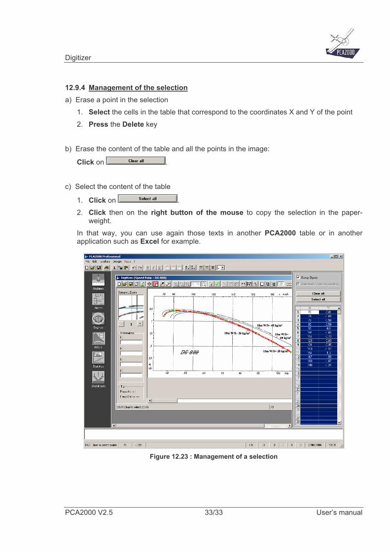
12.9.4 Management of the selection a) Erase a point in the selection
1. Select the cells in the table that correspond to the coordinates X and Y of the point 2. Press the Delete key
b) Erase the content of the table and all the points in the image:
Click on . c) Select the content of the table
1. Click on . 2. Click then on the right button of the mouse to copy the selection in the paper-
weight. In that way, you can use again those texts in another PCA2000 table or in another application such as Excel for example.
Figure 12.23 : Management of a selection


![[Skku2]20070730hd V2.5](https://img.pdfslide.us/doc/110x75/55a1dec51a28ab0c778b4603/skku220070730hd-v25.jpg)