Embed Size (px)
Citation preview

BeBeC-2014-21
1
LABORATORY MODEL OF ACOUSTIC CAMERA BASED ON DIRECT LOCALIZATION METHODS: CONCEPT,
IMPLEMENTATION AND SOME EXPERIMENTAL RESULTS
Miljko Erić1 and Milan Mišković
1
1School of Electrical Engineering, University of Belgrade
Bul. Kralja Aleksandra 73, 11000, Belgrade, Serbia
ABSTRACT
In previous BeBeC 2012 conference authors proposed direct localization
method based on steered covariance matrix approach, as an innovative method
which can be applied for acoustical mapping in acoustic camera. Meanwhile, the
authors realized low cost laboratory model of acoustic camera, named it LM-ERA.
It integrates hardware components such as microphone array, signal processing
platform with multichannel signal acquisition daughter boards, video camera and
PC computer. Application software with Graphical User Interface is developed in
MATLAB. Concept and practical implementation of laboratory model of acoustic
camera LM-ERA are shortly presented in the paper. Some experimental results of
acoustical mapping in real indoor environment are also presented in the paper. In
order to illustrate functionality and performances of the realized LM-ERA
acoustic camera preliminary experimental results provided by the use LM-ERA
acoustic camera are compared with results provided by Brüel & Kjær acoustic
camera for the same signal scenario.
1 INTRODUCTION
Motivation for design and realization of laboratory model of acoustic camera is related to the
Serbian national project of Ministry of Science and Technological Development TR 32026
called "Integration and Harmonization of Sound Insulation in Buildings in the Context of
Sustainable Housing". In this project we tend to apply technical solutions of acoustic camera
for development and verification of technical solutions for sound insulation in buildings. For
those purposes we needed some kind of acoustic camera. As the authors best knowledge,
almost all acoustic cameras available at market are delivered as laboratory instruments with
application software in closed form and possible option to export file with acquired data for
further off-line processing [1-5]. So our idea is to design and realize our own acoustic camera

5th
Berlin Beamforming Conference 2014 Erić and Mišković
2
as open scalable platform in order to implement acoustical mapping based on direct
localization method proposed by authors as innovative solution for acoustical mapping [6,7].
It is good option from the point of researching, development, implementation and testing of
new algorithms for acoustical mapping. The idea is also, that measurement data acquired by
the use of some other commercially available acoustic cameras can be imported and processed
by the application software of our acoustic camera. Hardware components such as
microphone array, signal processing platform with multichannel signal acquisition daughter
boards, video camera and PC computer are integrated in hardware. Application software with
Graphical User Interface is developed in MATLAB. At this moment it likes as laboratory
model but it is open scalable platform and further improvements and developments towards
prototype and possibly commercial product are possible.
Structure of the paper is the next. Brief review of acoustical mapping based on direct
localization is shortly presented in section 2. Concept of laboratory model and practical
implementation of hardware and software are shortly presented in the section 3. Some
experimental results of acoustical mapping in real indoor environment provided by the use of
realized laboratory model of acoustic camera LM-ERA are presented in the section 4.
2 BRIEF REVIEW OF THE ACOUSTIC MAPPING IN NEAR FIELD SIGNAL SCENARIO BASED ON DIRECT LOCALIZATION AND STEERED COVARINACE MATRIX APPROACH
Suppose near field acoustic multiple incident signal scenario with K acoustic sources at the
unknown locations denoted by the set of vectors 3; 1,k k K r . Summary acoustic signal
from K acoustic sources at the unknown locations denoted by the set of vectors 3; 1,k k K r received by the microphone array with L microphones on the known
locations denoted by the set of vectors 3; 1,l l L p can be modeled discrete time
domain in the next form [1]:
0
1
( ) ( ) ( ( )) ( ); 1,K
l l k k l k l
k
x n t b s n t n t n N
r r (1)
where ( )l kb r and ( ) /l k l k v r p r denote attenuation and propagation time delay of the
k-th signal, (0) (.)ks denotes signal of the k-th acoustic source on its location, N denotes total
number of signal samples and v denotes velocity of acoustic wave.
Steering preprocessing transformation in near-field signal scenario is performed in
frequency domain in such a way:
1
( , ) ( , ) ( ) k
Nj n tst
l l n l n
n
n T e
x r T r x (2)
where ( )l nx denotes vector with spectral samples of the acoustic signal on the l-th
microphone and vector 1( , )st xN
l n T C x r represents vector of the time samples on the l-th
microphone in the array after the steering preprocessing transformation. Matrix
( , ) LxL
l n C T r , which is so called steering matrix, is diagonal matrix with elements
/1( ) n lj v
lb e p r
r on the main diagonal.

5th
Berlin Beamforming Conference 2014 Erić and Mišković
3
Furthermore, steered covariance matrix ( )st LxLCR r , which is location dependent, can
be estimated as:
( ) { ( , ) ( , ) }st st st HE n T n T R r x r x r (3)
Steered-Bartlett estimator based on use of steered covariance matrix, can be defined as: _ ( ) ( )st BART H st
yP r v R r v (4)
Steered-MUSIC estimator can be defined as [7]:
_ 1( )
( ) ( )
st MUSIC
y H st st HP r
v E r E r v (5)
Vector 1( ) Lxv r in eq. 4. and 5. has a form: 1[1 1 ... 1]T Lx v (6)
Matrix ( )stE r is the noise subspace matrix of the steered covariance matrix ( )st
R r .
3 CONCEPT AND PRACTICAL IMPLEMENTATION OF LABORATORY MODEL OF ACOUSTIC CAMERA LM-ERA
Block scheme of the laboratory model of acoustic camera LM-ERA is shown on the Fig.1.
Main components of hardware platform of LM-ERA are microphone array with video camera,
signal-processing board with multichannel acquisition daughter boards, and laptop computer.
Microphone array is designed as planar array with four concentric circular arrays. Low cost
commercially available Genius MIC-01C microphones are used in functional model of
acoustic camera, but there is no limitation regarding geometry of microphone array and type
of used microphones. Genius web camera FaceCam 1005 is mounted in the center of
microphone array. Multichannel signal acquisition is performed by DSK_AUDIO4 four-
channel audio input/output acquisition card mounted as daughter board card on the Texas
Instruments TMS320C6713 DSP Starter Kit (DSK). At this moment just one such acquisition
card was available but up to four such acquisition card can be mounted on the same DSK
platform forming 16-channe acquisition system. Application Programming Interface (API) of
DSK_AUDIO4 is used to control of those cards from application software developed in
MATLAB. By the use of API function it is possible to choose sampling frequency and
programmable gains of input channels. DSK platform with just one DSK_AUDIO4 board is
used at this moment just for four-channel signal acquisition and streaming to PC, but
implementation of direct localization methods on signal processing boards for real-time
acoustical mapping is possible in the future. Application software of laboratory model of
acoustic camera LM-ERA is developed in MATLAB. It has object oriented graphical user
interface, Fig. 2, with many functional pushbuttons and pop-keys, and four windows W1, W2,
W3 and W4. Time samples of the signal from microphones are plotted on the W1 window.
Amplitude spectrum and spectrogram of the signal from selected microphone are plotted on
the W2 and W3 microphone, respectively. Results of acoustical mapping are plotted on the
W4 window. Measurement data with all required parameters (microphone geometry,
parameters of acquisitions, frames of images from camera etc) and results of acoustical
mapping can be memorized in file, and used late for repeated processing

5th
Berlin Beamforming Conference 2014 Erić and Mišković
4
Fig.1. Block scheme of the laboratory model of acoustic camera LM-ERA
.
Fig.2. Graphical User Interface (GUI) of the LM-ERA acoustic camera

5th
Berlin Beamforming Conference 2014 Erić and Mišković
5
4 RESULTS OF EXPERIMENTAL VERIFICATION IN REAL INDOOR ENVIRONMENT
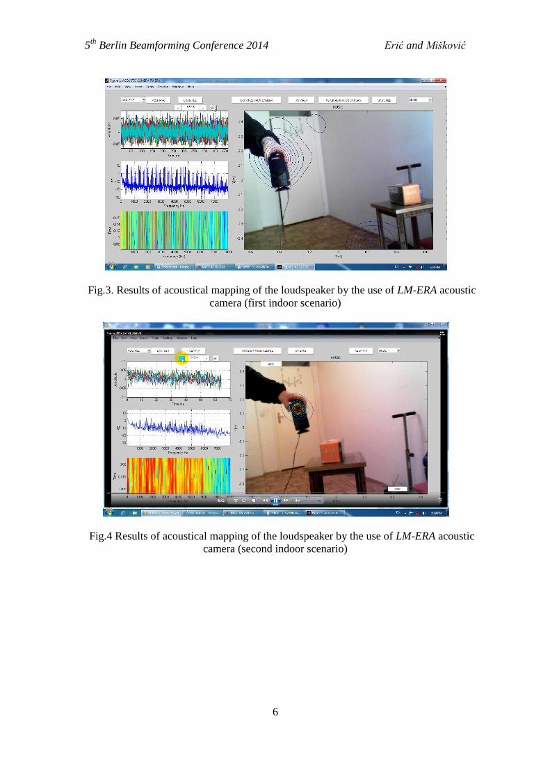
Results of acoustical mapping of the loudspeaker for two indoor scenarios, by the use of
realized LM-ERA acoustic camera, are presented on the Fig. 3. and Fig.4., respectively.
Acoustic equivalent of pseudo-noise sequence implemented in UWB MIMO channel sounder
[10] is used in measurements as acoustic signal transmitted from loudspeaker. Steered MUSIC
function is calculated on grid points in x0y plane for the value of z equal to the known
(measured) distance of loudspeakers from the plane of microphones (1.5 m) and for time
interval equal to 1024 signal samples (sampling frequency was 16ks/s). In both scenarios
mapping is repeated for many signal frames which correspond to different positions of
loudspeaker and results of localizations was always inside contour of the loudspeaker.
Contour plot (level curves) of results of mapping is plotted for values [0 dB,-1 dB,…,-9 dB,-
10 dB] of normalized values of Pm.
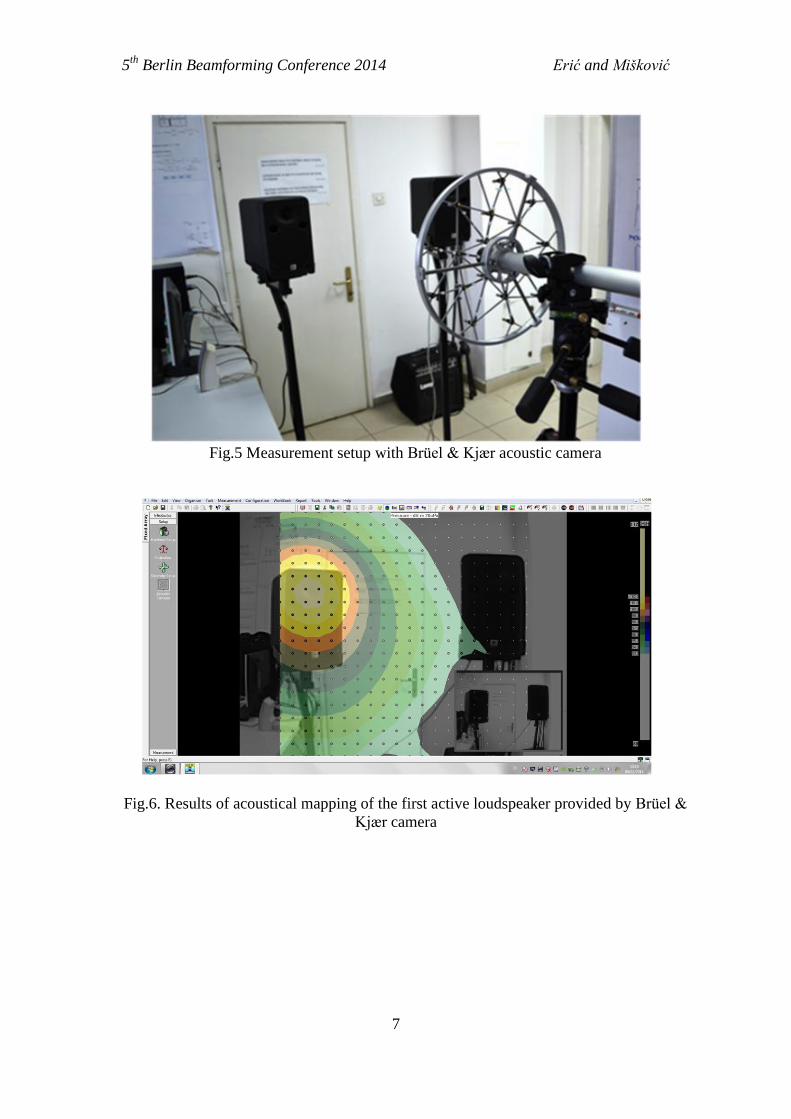
In the second measurement scenario, measurement setup with Brüel & Kjær acoustic
camera is used, Fig. 5. The same data acquired by Brüel & Kjær acoustic camera are used
both for acoustical mapping by the use of Brüel & Kjær acoustic camera and acoustical
mapping by the use realized LM-ERA acoustic camera. In the second measurement scenario
three signal scenarios are realized. Acoustic equivalent of pseudo-noise sequence
implemented in UWB MIMO channel sounder was transmitted from first loudspeaker in the
first scenario. Results of acoustical mapping by the use of realized LM-ERA acoustic camera
and by the use of Brüel & Kjær acoustic camera are presented on the Fig. 5 and Fig 6.,
respectively. MLS sequence was transmitted from the second loudspeaker in the second signal
scenario. Results of acoustical mapping of the second loudspeaker provided by the use of
realized LM-ERA acoustic camera and by the use of Brüel & Kjær acoustic camera are
presented on the Fig. 7 and Fig 8., respectively. In the third signal scenario both loudspeakers
are active at same time. Results of acoustical mapping of the third signal scenario provided by
the use of realized LM-ERA acoustic camera and by the use of Brüel & Kjær acoustic camera
are presented on the Fig. 9 and Fig 10., respectively. Step size in contour plots in figures 6-10
was the same (1dB). Preliminary results show that results of acoustical mapping provided by
LM-ERA acoustic camera are at least comparable with results provided by of Brüel & Kjær
acoustic camera.
5th
Berlin Beamforming Conference 2014 Erić and Mišković
6
Fig.3. Results of acoustical mapping of the loudspeaker by the use of LM-ERA acoustic
camera (first indoor scenario)
Fig.4 Results of acoustical mapping of the loudspeaker by the use of LM-ERA acoustic
camera (second indoor scenario)
5th
Berlin Beamforming Conference 2014 Erić and Mišković
7
Fig.5 Measurement setup with Brüel & Kjær acoustic camera
Fig.6. Results of acoustical mapping of the first active loudspeaker provided by Brüel &
Kjær camera

5th
Berlin Beamforming Conference 2014 Erić and Mišković
8
Fig.7. Results of acoustical mapping of the first active loudspeaker provided by LM-ERA
camera based on measurement data acquired on Brüel & Kjær camera
Fig.8. Results of acoustical mapping of the second active loudspeaker provided by Brüel &
Kjær camera

5th
Berlin Beamforming Conference 2014 Erić and Mišković
9
Fig.9. Results of acoustical mapping of the second active loudspeaker provided by LM-
ERA camera based on measurement data acquired on Brüel & Kjær
Fig.10. Results of acoustical mapping of the first and second active loudspeaker provided
by Brüel & Kjær camera

5th
Berlin Beamforming Conference 2014 Erić and Mišković
10
Fig.11. Results of acoustical mapping of the first and second active loudspeaker provided
by LM-ERA camera based on measurement data acquired on Brüel & Kjær camera
ACKNOWLEDGMENT
This work was supported by the Serbian national project of Ministry of Education and
Science TR 32026 called "Integration and Harmonization of Sound Insulation in Buildings in
the Context of Sustainable Housing".
We wish to acknowledge to PhD student Miloš Bjelić for his help in realization of
measurements using Brüel & Kjær acoustic camera.
.
5 SUMARY AND CONCLUSION
Developed low cost laboratory model of acoustic camera based on direct localization
method is shortly presented in this paper. Hardware components such as microphone array
video camera, signal processing platform with multichannel signal acquisition daughter
boards, and PC computer and application software with object oriented Graphical User
Interface developed in MATLAB are integrated in realized laboratory model. Functionality
and performance of the laboratory model are illustrated by some experimental results of
indoor acoustical mapping and compared with results for the same signal scenario provided
by Brüel & Kjær acoustic camera. As it can be seen, results of acoustical mapping provided
by realized laboratory model for the same signal scenario are quite comparable with results
provided by Brüel & Kjær acoustic camera.

5th
Berlin Beamforming Conference 2014 Erić and Mišković
11
REFERENCES
[1] www.acoustic-camera.com
[2] www.lmsintl.com
[3] www.bksv.com
[4] www.norsonic.com
[5] www.microflown.com
[6] Miljko Erić, Milan Mišković: " Near-field Steered Covariance Matrix Approach for
Resolution and Dynamic Improvement in Acoustic Cammera Application", Proc. of the
4th
Berlin Beamformer Conference BeBeC-2012-4,22-23.02. 2012., Berlin, pp.1-4,
ISBN: 978-3-942709-04-
[7] M.Erić, "Some Research Aspects of Acoustic Camera" 19th
Telecommunications forum
TELFOR 2011, Serbia, Belgrade, November 22-24,2011, pp.1036-1039
[8] "Beamforming", Brüel&Kjær Technical Review, No.1. 204 available on site
www.bksv.com
[9] Miomir Mijić, Draško Mašović, Dragana Šumarac Pavlović and Mirjana Adnađević
,"A Model of Planar Microphone Array Realized with Low-cost Multimedia
Microphones", 19th
Telecommunications forum TELFOR 2011, Serbia, Belgrade,
November 22-24,2011, pp.1040-1043
[10] Zetik, R., Thomä, R. and Sachs, J.:‘Ultra-wideband real-time channel sounder design
and application’, URSI International symposium on electromagnetic theory, Pisa, Italy,
May 2004.