Embed Size (px)
Citation preview

Machine Components: Shafts,Keys, and Couplings
ME 72 Engineering DesignLaboratory

Shafts• Shaft Functions
– Provide an axis of rotation
– Used to transmit power
– Used to position/mount gears, pulleys,bearings, etc.
• Shaft Design Issues– Geometry (stepped cylindrical geometry)
– Loading
– Stress and Deflection (Strength and Rigidity)

Shaft Design Procedure
• Develop a static free-body diagram.
• Draw a bending moment diagram in twoplanes.
• Develop a torque diagram.
• Establish the location of the critical crosssection.
• Perform a Stress Analysis for sizing.

ShaftAssembly
Shaft Assembly.
(a) Shaft with two bearings atA and B and two gears withresulting forces P1 and P2;
(b) free-body diagram oftorque and forces resultingfrom assembly drawing;
(c) moment diagram in x-zand x-y planes;
(d) torque diagram.

Loads
• Static Loading– Radial
– Tangential
– Axial (Thrust)
• Dynamic (Cyclic) Loads– Fully reversed
– Repeated
– Fluctuating

Stresses
• Stress due to Axial Loading
• Stress due to Bending
• Stress due to Torsion
σπx
F
d=
42
σ xM y
I= σ
πmax =32
3M
d
τπxy
T
d=
163
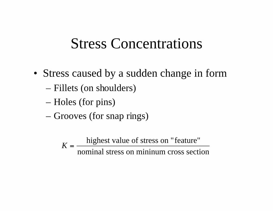
Stress Concentrations
• Stress caused by a sudden change in form– Fillets (on shoulders)
– Holes (for pins)
– Grooves (for snap rings)
K =highest value of stress on "feature"
nominal stress on mininum cross section

σ σmax = K d

Shaft Design Guidelines
• Keep shafts short and minimize cantilever designs.
• Hollow shafts have better stiffness/mass ratios, but aremore expensive.
• Configure shaft geometry to reduce stress concentrations.
• Remember that gears can produce radial, tangential, andaxial loads.
• Be aware of maximum shaft deflection requirements ofbearings.
• Shaft natural frequency should be as high as practical.

Constraining Parts on Shafts
• For Torque Transfer– Keys
– Set screws
– Pins
– Splines
– Tapered fits
– Press or shrink fits
• For Axial Location– Nut and cotter pins
– Sleeves
– Shoulders
– Ring and groove
– Collar and set screw
– Split hub


Couplings• Couplings transmit torque and motion between
shafts in the presence of various types ofmisalignment
• Types of Misalignment– Angular
– Parallel
– Torsional
– Axial


Types of Couplings
• Rigid Couplings– Set-screw
– Keyed
– Clamped
• Flexible Couplings– Jaw type
– Gear, spline, grid, chain
– Helical and bellows
– Linkages
– Universal Joints• Used in pairs
• Basic Specs Include: nominal and peaktorque, misalignment tolerances, shaft size,operating temp, speed range, and backlash.


Summary
• Shafts transmit rotary power.
• Shafts are typically designed for maximumstiffness and minimum deflection.
• Keys and similar elements are used to attachparts and align components along a shaft.
• Couplings are used to transmit powerbetween two misaligned shafts.

References
• Hindhede, U., Zimmerman, J., Hopkins, B., et al.,Machine Design Fundamentals: A Practical Approach,Englewood Cliffs: Prentice Hall, 1983.
• Shigley, J., and Mischke, C., Mechanical EngineeringDesign, 5th Ed., San Francisco: McGraw-Hill Inc., 1989.
• Norton, R., Machine Design: An Integrated Approach,Upper Saddle River: Prentice-Hall, 1998.
• Hamrock, B., Jacobson, B., and Schmid, S., Fundamentalsof Machine Elements, San Francisco, WCB McGraw-Hill,1999


![INDEX [file.seekpart.com]file.seekpart.com/keywordpdf/2010/11/25/2010112510365625.pdf · ashok leylandbeaver/hippo 1 ... ashok leyland 1 ** in old models. comet/viking/cheetah tauras](https://img.pdfslide.us/doc/110x75/5abdb4ad7f8b9a5d718c078f/index-file-file-leylandbeaverhippo-1-ashok-leyland-1-in-old-models.jpg)