Embed Size (px)
Citation preview
KTA-200 Dual Amplifier / Attenuator
Dual DC Amplifier / Attenuator
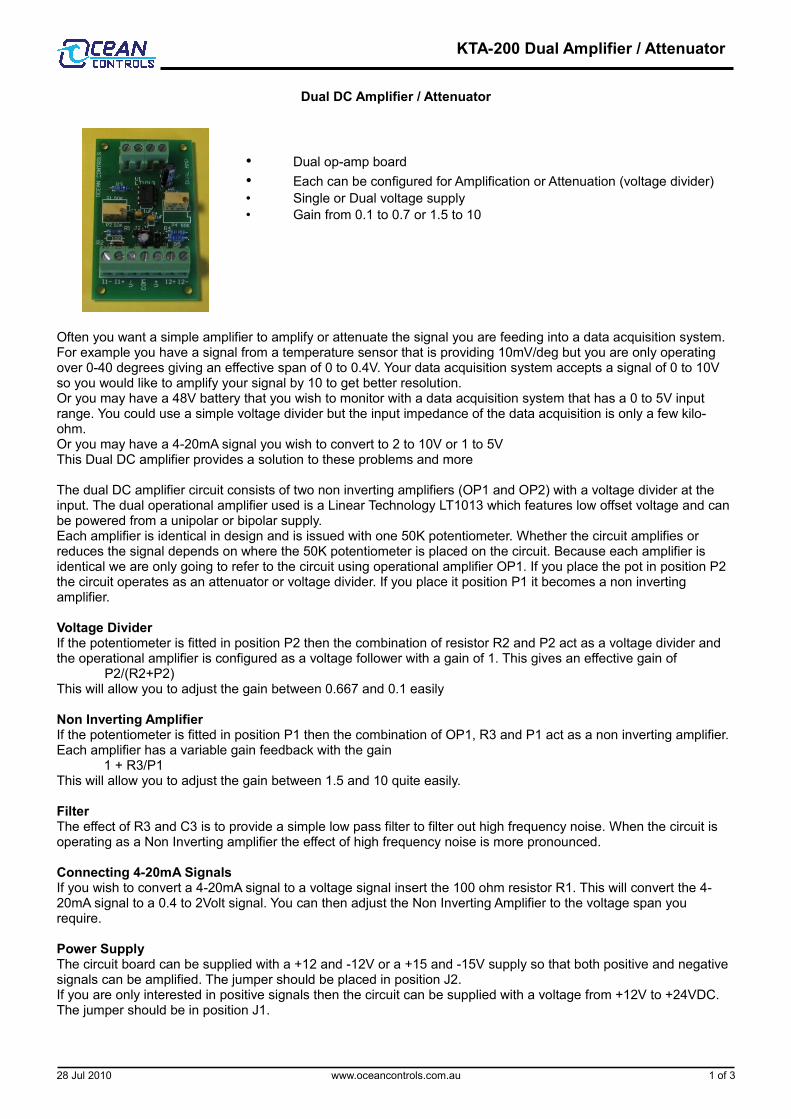
• Dual op-amp board• Each can be configured for Amplification or Attenuation (voltage divider)• Single or Dual voltage supply• Gain from 0.1 to 0.7 or 1.5 to 10
Often you want a simple amplifier to amplify or attenuate the signal you are feeding into a data acquisition system. For example you have a signal from a temperature sensor that is providing 10mV/deg but you are only operating over 0-40 degrees giving an effective span of 0 to 0.4V. Your data acquisition system accepts a signal of 0 to 10V so you would like to amplify your signal by 10 to get better resolution.Or you may have a 48V battery that you wish to monitor with a data acquisition system that has a 0 to 5V input range. You could use a simple voltage divider but the input impedance of the data acquisition is only a few kilo-ohm.Or you may have a 4-20mA signal you wish to convert to 2 to 10V or 1 to 5V This Dual DC amplifier provides a solution to these problems and more
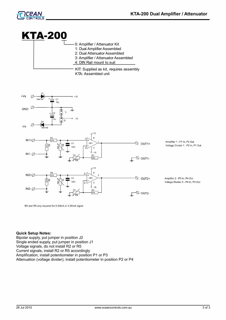
The dual DC amplifier circuit consists of two non inverting amplifiers (OP1 and OP2) with a voltage divider at the input. The dual operational amplifier used is a Linear Technology LT1013 which features low offset voltage and can be powered from a unipolar or bipolar supply.Each amplifier is identical in design and is issued with one 50K potentiometer. Whether the circuit amplifies or reduces the signal depends on where the 50K potentiometer is placed on the circuit. Because each amplifier is identical we are only going to refer to the circuit using operational amplifier OP1. If you place the pot in position P2 the circuit operates as an attenuator or voltage divider. If you place it position P1 it becomes a non inverting amplifier.
Voltage DividerIf the potentiometer is fitted in position P2 then the combination of resistor R2 and P2 act as a voltage divider and the operational amplifier is configured as a voltage follower with a gain of 1. This gives an effective gain of
P2/(R2+P2)This will allow you to adjust the gain between 0.667 and 0.1 easily
Non Inverting AmplifierIf the potentiometer is fitted in position P1 then the combination of OP1, R3 and P1 act as a non inverting amplifier. Each amplifier has a variable gain feedback with the gain
1 + R3/P1This will allow you to adjust the gain between 1.5 and 10 quite easily. FilterThe effect of R3 and C3 is to provide a simple low pass filter to filter out high frequency noise. When the circuit is operating as a Non Inverting amplifier the effect of high frequency noise is more pronounced.
Connecting 4-20mA SignalsIf you wish to convert a 4-20mA signal to a voltage signal insert the 100 ohm resistor R1. This will convert the 4-20mA signal to a 0.4 to 2Volt signal. You can then adjust the Non Inverting Amplifier to the voltage span you require.
Power SupplyThe circuit board can be supplied with a +12 and -12V or a +15 and -15V supply so that both positive and negative signals can be amplified. The jumper should be placed in position J2. If you are only interested in positive signals then the circuit can be supplied with a voltage from +12V to +24VDC. The jumper should be in position J1.
28 Jul 2010 www.oceancontrols.com.au 1 of 3
KTA-200 Dual Amplifier / Attenuator
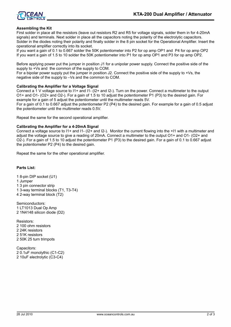
Assembling the KitFirst solder in place all the resistors (leave out resistors R2 and R5 for voltage signals, solder them in for 4-20mA signals) and terminals. Next solder in place all the capacitors noting the polarity of the electrolytic capacitors. Solder in the diodes noting their polarity and finally solder in the 8 pin socket for the Operational Amplifier. Insert the operational amplifier correctly into its socket.If you want a gain of 0.1 to 0.667 solder the 50K potentiometer into P2 for op amp OP1 and P4 for op amp OP2If you want a gain of 1.5 to 10 solder the 50K potentiometer into P1 for op amp OP1 and P3 for op amp OP2.
Before applying power put the jumper in position J1 for a unipolar power supply. Connect the positive side of the supply to +Vs and the common of the supply to COM.For a bipolar power supply put the jumper in position J2. Connect the positive side of the supply to +Vs, the negative side of the supply to –Vs and the common to COM.
Calibrating the Amplifier for a Voltage SignalConnect a 1 V voltage source to I1+ and I1- (I2+ and I2-). Turn on the power. Connect a multimeter to the output O1+ and O1- (O2+ and O2-). For a gain of 1.5 to 10 adjust the potentiometer P1 (P3) to the desired gain. For example for a gain of 5 adjust the potentiometer until the multimeter reads 5V.For a gain of 0.1 to 0.667 adjust the potentiometer P2 (P4) to the desired gain. For example for a gain of 0.5 adjust the potentiometer until the multimeter reads 0.5V.
Repeat the same for the second operational amplifier.
Calibrating the Amplifier for a 4-20mA SignalConnect a voltage source to I1+ and I1- (I2+ and I2-). Monitor the current flowing into the +I1 with a multimeter and adjust the voltage source to give a reading of 20mA. Connect a multimeter to the output O1+ and O1- (O2+ and O2-). For a gain of 1.5 to 10 adjust the potentiometer P1 (P3) to the desired gain. For a gain of 0.1 to 0.667 adjust the potentiometer P2 (P4) to the desired gain.
Repeat the same for the other operational amplifier.
Parts List:
1 8-pin DIP socket (U1)1 Jumper 1 3 pin connector strip1 3-way terminal blocks (T1, T3-T4)4 2-way terminal block (T2)
Semiconductors:1 LT1013 Dual Op Amp2 1N4148 silicon diode (D2)
Resistors:2 100 ohm resistors2 24K resistors2 51K resistors2 50K 25 turn trimpots
Capacitors:2 0.1uF monolythic (C1-C2)2 10uF electrolytic (C3-C4)
28 Jul 2010 www.oceancontrols.com.au 2 of 3
KTA-200 Dual Amplifier / Attenuator
Quick Setup Notes:Bipolar supply, put jumper in position J2Single ended supply, put jumper in position J1Voltage signals, do not install R2 or R5Current signals, install R2 or R5 accordinglyAmplification, install potentiometer in position P1 or P3Attenuation (voltage divider), install potentiometer in position P2 or P4
28 Jul 2010 www.oceancontrols.com.au 3 of 3
KTA-2000: Amplifier / Attenuator Kit1: Dual Amplifier Assembled2: Dual Attenuator Assembled3: Amplifier / Attenuator Assembled4: DIN Rail mount to suit
KIT: Supplied as kit, requires assemblyKTA: Assembled unit