Embed Size (px)
Citation preview

ORIGINAL ARTICLE
Kinematic design of a novel 4-DOF parallel mechanismfor turbine blade machining
Hiwa Ghaffari & Gholamhasan Payeganeh &
Mohammadreza Arbabtafti
Received: 23 December 2013 /Accepted: 28 May 2014# Springer-Verlag London 2014
Abstract This paper presents a novel four-degree-of-freedom (4-DOF) partially decoupled parallel mechanismwhich can generally be used in machining processes, buthere, it is particularly designed for turbine blade machin-ing. Forward and inverse kinematic formulations havebeen derived for proposed mechanism, and using Jacobi-an matrix has proved that the mechanism has no singu-larity in its workspace. The workspace has been analyzedusing a geometric approach, and the required strokelengths of mechanism’s actuators for the defined taskhave been acquired.
Keywords Parallel mechanism . Hybridmachine tool .
Kinematics . Blade machining .Workspace analysis .
Singularity
1 Introduction
Since 1994 when the first parallel kinematic machinetools were presented to the market, only few cases ofthese machine tools have been turned out to be compa-rable with their serial-type conventional counterparts.The failure of these machine tools seems to derive fromsome shortcomings such as small workspace, relativelylow dexterity, and limited angular movements. Thesedrawbacks caused parallel machine tools develop lessthan what was expected in spite of some advantages likepotentially high stiffness and accuracy [1–3].
Exploring successful practical cases of parallel machinetools, one can find some common reasons for their success,mainly [4]:
& Mostly, the right design has been adapted to the specificapplication. Most of the successful parallel machine toolswere designed to perform one or a few tasks and not asversatile machine tools. This is true especially about fullparallel machine tools.
& Using parallel mechanisms in combination with serialones (hybridization). This work brings about advantagesof improved stiffness and accuracy while keeping dexter-ity and tool rotating capability at a high level.
& Using parallel mechanisms with decoupled degrees offreedom, if possible. Such mechanisms have often beendesirable because they have simpler kinematics.
Different four-degree-of-freedom (4-DOF) parallel mecha-nisms have been designed and analyzed in the past twodecades. Roland [5] reported the design and prototyping oftwo 3T1R (three translations, one rotation) parallel robots,KANUK and MANTA, and presented their kinematics andsingularities. Wen-Jia et al. [6] offered a 2T2R (two transla-tions, two rotations) parallel mechanism and, after obtainingits kinematic equations, suggested a five-axis machine toolusing this mechanism. Sangveraphunsiri and Tantawiroon [7]presented the kinematics design and singularity analysis of a3T1R parallel robot with linear actuators which they offeredfor general machining purposes. Wu et al. [8, 9] offered a newfamily of 4-DOF parallel manipulators for high-speed pickand place and machining applications, called H4, based on theidea of Delta robot. Briot et al. [10] reported kinematic designand prototyping of a partially decoupled 4-DOF 3T1R parallelmanipulator in which displacements of the platform in thehorizontal plane are decoupled from the platform’s translationalong the vertical axis. Pierrot et al. [11] introduced the
H. Ghaffari :G. Payeganeh :M. Arbabtafti (*)Shahid Rajaee Teacher Training University, Tehran, Islamic Republicof Irane-mail: [email protected]
Int J Adv Manuf TechnolDOI 10.1007/s00170-014-6015-0

kinematic and dynamic design of 4-DOF parallel robot whichthey named Par4. Experimental results about maximumachievable speed and acceleration of the mechanism’s proto-type and also its kinematic and dynamic optimization arereported. Kong and Gosselin [12] presented forward displace-ment analysis and the type two singularity analysis of aquadratic 4-DOF 3T1R parallel manipulator namedQuadrupteron. Kuo and Dai [13] offered a new 4-DOF fullydecoupled parallel manipulator for application in minimallyinvasive surgery. They solved inverse kinematics problem,identified singular configuration via Jacobian analysis, andanalyzed the reachable and collision-free workspaces of theproposed manipulator. Ye [14] presented singularity analysisof a class of 4-DOF parallel mechanism. These kinds ofmechanisms have one constraint driven limb in addition tofour S-P-S driving limbs and may have 2T2R, 1T3R, or 3T1Rdegrees of freedom. Moving character has been analyzed byusing screw theory, and the different degrees of freedom havebeen calculated by revised Kutzbach-Grübler formula.
However, the aim of all industrial parallel mechanismmachine tools is to machine all possibly complicated surfaces[2], but task-based parallel machine tools have been alsopresented such as those optimized for dedicated machines[2, 15]. Although blade machining is important, few re-searches are available in the field of designing of parallelmechanisms particularly for this process. Li et al. [16] havedealt with dynamic comparison and optimization of two 3-DOF parallel mechanisms for using in a blade machininghybridmachine tool. In another research in this category, Yanget al. [17] also have used a three-degree-of-freedom parallelrobot for constructing a hybrid six-axis machine tool forturbine blades grinding. Since blade machining is a compli-cated and important task in industry, it is convincible to havemore researches on dedicated machine design for this process.
In all the above-reviewed papers, one or all of the followingshortcomings can be seen:
& Complicated nonlinear kinematics equations of designedor used mechanisms.
& Low workspace volume or irregularity of its shape whichmakes the mechanism inappropriate for machining tasks.
& None task-based design and optimization of mechanismscauses the results to be immeasurable. For example, withoutconsidering a specific task, limitation in maximum rotationof angular degrees of freedom can be a serious drawback.
In this work, in order to enjoy benefits of parallel mecha-nisms in machining process of gas turbine blades, which is oneof the most complicated machining tasks, a novel four-degree-of-freedom parallel mechanism will be introduced. This mech-anism have been designed and optimized based on blade ma-chining demands, and necessary features for using it in a hybridsix-axis machine tool are taken into consideration.
2 Turn milling and design consideration
One of the most effective and popular methods for machininggas turbine blades, especially small to medium size blades (upto 600 mm in length), is turn milling which is defined as themilling of a curved surface while rotating the workpiecearound its center point or longitudinal axis (Fig. 1). Thisprocess has made it possible for different industries to manu-facture many components which would otherwise have beendifficult to make and needed a number of different machiningoperations. Turn milling excels when manufacturing compo-nents with unsymmetrical forms is considered. If correctlyapplied, turn milling has also some other attractive advantagesin comparison with other strategies, including: higher metalremoval, better chip control, smaller cutting forces, and bettercoping with interrupted cuts [18].
Turn milling centers are versatile machines in which thecutting head can either hold a single cutting edge whichremains stationary (in which case, the machining operationis fundamentally a turning process) or a multi-tool cuttinghead rotating just in its own place (as in a milling process)[18].
When a blade structure is turn milled, the workpiecemounted in a turning fixture slowly rotates along its longitu-dinal axis in front of the tool, while the cutting head moves inthree orthogonal axes and rotates around one or two axes. Ofcourse, one or more of the linear movements of tool head canbe applied to worktable on which the revolving workpiece ismounted. In practice, the profile is thus machined in a singlecutting engagement while the milling tool moves slowly alongthe revolving workpiece (Fig. 2).
In this work, it is assumed that the worktable of the ma-chine tool can translate along the longitudinal direction of theblade and the blade can be rotated about its longitudinal axis.So to perform blade machining, the tool head mechanismshould also have at least three degrees of freedom (two trans-lational and one rotational). However, more degrees of free-dom for the tool head mechanism can improve its flexibilityand dexterity in turn milling strategy, so the tool head mech-anism in this work has been designed to have 4-DOFs (twotranslational and two rotational).
3 The mechanism description
Figure 3 shows a schematic diagram of the designed 2T2R(two translational and two rotational) 4-DOF parallel mecha-nism. As it can be seen, the base of the mechanism is con-nected to the milling head by means of four kinematic chainsincluding two P-C-U-P and one P-R-C-P chains which have acommon P joint and also one P-P-R-R chain (P, R, U, and Care prismatic, revolute, universal, and cylindrical joints,respectively).
Int J Adv Manuf Technol

CAD models of the designed mechanism are provided inFigs. 4, 5, 6, and 7. Four sliders, S1, S2, S3, and S4, can beseparately actuated using four motors. Linear movements ofthese sliders make the milling head to have two displacements(along y and z axes) and two revolutions (about the x″ and y″axes). Simultaneous actuation of sliders S1, S2, and S3 makethe milling head to move along the z-axis. A single actuationof the slider S4 causes the milling head to move along the y″-axis, while a pure ymovement of the head needs the actuationof S1, S2, and S3 as well as S4 actuation. Rotation of themilling head about the y″-axis occurs by actuating S1 and S2in the opposite directions. Furthermore, simultaneous actua-tion of S1 and S2 in the opposite direction of S3 can make themilling head to rotate about the x″-axis.
The combined prismatic-revolute (cylindrical) jointsconnecting link L1 to sliders S1 and S2 make it possible forlink L1 to have variable length which is necessary for itsrotating capability (Fig. 5). The universal joint connects linksL1 and L2; the cylindrical (prismatic-revolute) joint connectslinks L2 and L5 (Fig. 6); and the revolute joint connects link L5
with slider S3 (Fig. 6), all together facilitate the simultaneousrotation of the milling head about the x″ and y″ axes.
It should be noted that in a universal joint, the angularvelocities of input and output drive shafts are not linearlyrelated. So, when the drive shaft rotates at a constant speed,the driven shaft speed varies with angle of rotation in aperiodic manner. This condition causes varying feed rate forthe mechanismwhenmachining a workpiece and also leads to
vibration and wear. This problem can be solved in two ways.The first way is to use a constant velocity (CV) joint, instead.In these joints, a constant output angular velocity will beobtained when the input shaft revolves at a constant speed.There are several types of CV joints with different propertiessuch as Double Hook’s type, pot-type and Carl Weiss joints.As the use of CV joint instead of the universal joint in themechanism has no effect on the kinematics analysis, it will notbe mentioned in the following sections. The second way is to
Fig. 1 Turn milling principles
Fig. 2 Turn milling of a turbine blade [18]
Fig. 3 Kinematic structure of the mechanism
Fig. 4 CAD model of the mechanism
Int J Adv Manuf Technol

keep the universal joint but to control the speed of the relatedactuators, S1 and S2, in order to have constant speed in theoutput shaft.
4 Kinematics
Forward and inverse kinematic problems have been solved forthe proposed 2T2R mechanism. This section describes theforward and inverse kinematic problems. For this purpose,three frames will be used: {A}: o-xyz is the reference framewhich is attached to the top of the mechanism so as it’s z-axisis coincident with universal joint’s axis. {B}: o′-x y z and{C}: o″-x″y″z″ are mobile frames which are attached to thecenter of the milling head. {B} is fixed orientation, but {C}rotates with the tool (T). The tool vector will remain inopposite direction of the z″-axis.
4.1 Forward kinematic problem
Here, the tool’s position and orientation for a given actuatedset of sliders S1 to S4 will be developed. Figure 8 shows theside view of milling head and its attached frame. β is therotation angle of the head frame about y″-axis. Using thepositions of S1 and S2 in the reference frame, which are (0,
b/2,−c1) and (0,−b/2,−c2), respectively, it can be written asfollows:
β ¼ tan−1c2−c1b
� �ð1Þ
Front view of the mechanism is shown in Fig. 9. It isobvious from the figure that the position of the head frames(o′ and o″) in y direction is as follows:
y ¼ c4 ð2Þ
c′ is defined as the mean value of the vertical positions ofthe sliders S1 and S2:
c0 ¼ c1 þ c22
ð3Þ
Fig. 5 Rule of prismatic anduniversal joints in milling head’sroll and pitch revolving
Fig. 6 Detail view of slider S3 and its relation with links L5 and L2 Fig. 7 Attached frames used for kinematic
Int J Adv Manuf Technol

Having the position of the slider S3 as (0, a, −c3), then therotation angle of the head frame about x″-axis can be writtenas follows:
α ¼ tan−1c3−c0
a
� �ð4Þ
Also, according to Fig. 8, the z position of the head framewith respect to reference frame can be derived as follows:
z ¼ c0 þ c4tanα ð5Þ
So, the forward kinematic equations are as follows:
y ¼ c4
z ¼ c1 þ c22
þ c42c3− c1 þ c2ð Þ
2a
� �
α¼ tan−12c3− c1 þ c2ð Þ
2a
� �β ¼ tan−1
c2−c1b
� �
8>>>>>>><>>>>>>>:
ð6Þ
Using x-y-z Euler angles, the rotation matrix which de-scribes {C} relative to {B} will be obtained:
cBRx0y0z0 α;β; 0ð Þ ¼
cosβ 0 sinβsinαsinβ cosα −sinαcosβ−cosαsinβ sinα cosαcosβ
24
35 ð7Þ
The tool vector in frame {C} can be expressed as follows:
cT¼00−1
24
35 ð8Þ
So, the tool orientation in frame {B} and consequently inframe {A} can be obtained as the following:
BT¼BCR
cT¼−sinβ
sinαcosβ−cosαcosβ
24
35 ð9Þ
4.2 Inverse kinematics
In order to obtain better surface finish for a turbine blade, it isimportant for the tool to remain perpendicular to blade’ssurface during turn milling. So, in a given point on the bladesurface like K (Fig. 10), the normal vector of the surface (G)defines the direction of the approach for the tool.
In order to define tool machining trajectory for sophisticat-ed parts like turbine blades, usually CAM software is used.CAM programs get a CAD model of the part and generate acutter location (CL) data file that contains all necessary posi-tions and orientations of the cutter with respect to workpiececoordinate system. Using the CL data and the coordinatesystem fixed to the rotating workpiece, the tool orientation,i.e., φ and γ, with respect to the machine’s fixed frame can bederived. These angles are shown in Fig. 11.
As shown in Fig. 11, the tool orientation using angles of φand γ in frame {B} can be obtained as the following:
Fig. 8 Kinematics of milling head when revolving about y″-axis
Fig. 9 Kinematic parameters of the mechanism from front view
Int J Adv Manuf Technol

BTsinγcosφsinγsinφ−cosγ
24
35 ð10Þ
Now, we can find anglesα and β from the input angles ofφand γ equalizing (9) and (10):
sinγcosφsinγsinφ−cosγ
24
35 ¼
−sinβsinαcosβ−cosαcosβ
24
35 ð11Þ
So, the milling head’s rotation angels are obtained as follows:
β ¼ sin−1 −sinγcosφð Þα ¼ sin−1
sinγsinφcosβ
� �8<: ð12Þ
Having α, β, and position of the milling head in referenceframe (x and y), positions of the mechanism’s sliders can becalculated. The inverse kinematic equations have been direct-ly derived from the forward equations. Equation (1) can berewritten as the following:
c2−c1 ¼ btanβ ð13Þ
Also using Eq. (2) and (6), it will be obtained:
c1 þ c2 ¼ 2 zþ ytanαð Þ ð14Þ
From simultaneous solving of Eqs. (13) and (14), c1 and c2will be acquired as follows:
c1 ¼ z–ytanα– b=2ð Þtanβ ð15Þ
c2 ¼ z–ytanαþ b=2ð Þtanβ ð16Þ
Furthermore, according to Eq. (5), c3 can be found asfollows:
c3 ¼ a–yð Þtanαþ z ð17Þ
and c4 will be found from Eq. (2):
c4 ¼ y ð18Þ
So, the inverse kinematic equations of the designed 2T2Rmechanism are summarized as follows:8>><>>:
c1 ¼ z–ytanα− b=2ð Þtanβc2 ¼ z–ytanαþ b=2ð Þtanβc3 ¼ a–yð Þ tanα þ zc4 ¼ y
ð19Þ
5 Velocities
The time derivative of the forward kinematics equations yieldsthe velocity relations of the mechanism:
X: ¼ JC
: ð20Þ
in which X:and C
:are the velocity vectors of the milling head
and the actuators respectively and J is the Jacobian matrix. Infact, the matrix will give a mapping between the linear
Fig. 10 Determination of the tool orientation using the normal vector ofthe blade’s surface
Fig. 11 Tool orientation description in fixed orientation frame
Int J Adv Manuf Technol

velocities of the actuators to the linear and angular velocitiesof the milling head. The matrix will be used in the singularityanalysis. The velocity equations are derived as follows:
y ̇ ¼ c:
4 ð21Þ
z ̇ ¼ 1=2ð Þ 1ð − c4=að Þ½ �c ̇1 þ 1=2ð Þ 1ð − c4=að Þ½ �c ̇
2
þ c4=að Þc ̇3 þ 2c3− c1 þ c2ð Þ
2a
� �c ̇4 ð22Þ
α ̇ ¼ −2a4a2 þ 2c3−c1−c2ð Þ2
" #c ̇1 þ −2a
4a2 þ 2c3−c1−c2ð Þ2" #
c ̇2
þ 4a
4a2 þ 2c3−c1−c2ð Þ2" #
c ̇3 ð23Þ
β ̇ ¼ −bb2 þ c2−c1ð Þ2
" #c ̇
1 þb
b2 þ c2−c1ð Þ2" #
c ̇2 ð24Þ
Writing velocity equations in matrix form yields the Jaco-bian matrix of the mechanism:
y ̇
z ̇
α ̇
β ̇
2664
3775 ¼
0 0 0 1a−c42a
a−c42a
c4a
c3−c0
a
� �−a
2a2 þ 2 c3−c0ð Þ2−a
2a2 þ 2 c3−c0ð Þ2a
a2 þ c3−c0ð Þ2 0
−bb2 þ c2−c1ð Þ2
b
b2 þ c2−c1ð Þ2 0 0
266666664
377777775
c ̇1
c ̇2
c ̇3
c ̇4
2664
3775 ð25Þ
6 Singularities
Singular configurations are particular poses of the end-effector for which parallel robots lose their inherentinfinite rigidity and in which the end-effector will have
uncontrollable degrees of freedom [1]. In a possiblesingular configuration, the Eq. (20) has no solutions,i.e., Jacobian matrix is not invertible. So, it should bedetermined that if in any pose, the determinant of Ja-cobian matrix is equal to zero:
Fig. 12 aOrientation workspace.b Total orientation workspace incut plane. c Revised totalorientation workspace in cutplane
Int J Adv Manuf Technol

Jj j ¼ 0 ð26Þ
The mechanism’s Jacobian matrix determinant is obtainedas follows:
Jj j ¼ −abm b2 þ c2�
" #ð27Þ
in which
m ¼ a2 þ c3−c0ð Þ2c ¼ c2− c1
ð28Þ
It is obvious that the Eq. (26) has no answer, so themechanism has no singularities in its workspace.
7 Workspace analysis
A graphical representation of the workspace of parallel robotswill be possible only for 3-DOF robots. For robots with n>3-DOF, workspace representation will be possible only if we fixn−3 pose parameters. Different types of workspace will beobtained regarding the number and type of parameters whichare fixed or the kind of constraints that are imposed on them[1].
Constant orientation workspace defined as all possiblelocations of the tool that can be reached with a givenorientation. All the possible orientations that can be
Fig. 13 Constant orientation workspace projected in y–z plane: a α=0 (maximal workspace); b α>0
Fig. 14 Constant orientationworkspace: a α=0; b α>0
Int J Adv Manuf Technol
reached while the tool is in a fixed location are calledorientation workspace. All the locations of the tool thatmay be reached with at least one orientation of themilling head form reachable workspace. Total orientationworkspace is all the locations of the tool that may bereached with all the orientations among a set defined byranges on the orientation angles. A particular case oftotal orientation workspace for which the ranges of therotation angles is [0, 2π] usually is labeled as dexterousworkspace [1].
There are various approaches to acquire the workspace ofparallel robots including analytical, numerical, discretisation,and geometrical. In this paper, geometrical approach is used todetermine the mechanism’s workspace.
Figure 12 shows the mechanism in the x–z plane. Ineach position on line OP, actuating S1 and S2 in theopposite directions cause the milling head rotates from−βmax to βmax (Fig. 12a). Repeating this procedure for allpoints on line OP, the 2D total orientation workspace inthe x–z plane will be obtained (Fig. 12b). Since thesliders S1 and S2 are limited in their courses, achievableamounts for β gradually become confined as the millinghead gets closer to the maximum and minimum z posi-tions. So, the 2D total orientation workspace in x–z planeshould be revised as shown in Fig. 12c.
Now, the mechanism will be considered as a 2T1Rplanar mechanism in the y–z plane as shown in Fig. 13.Regarding maximum course length of mechanism’s
Fig. 15 Total orientationworkspace: a determiningmethod; b result workspace
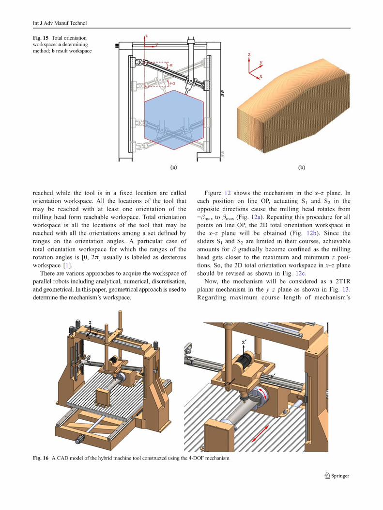
Fig. 16 A CAD model of the hybrid machine tool constructed using the 4-DOF mechanism
Int J Adv Manuf Technol

sliders, the constant orientation workspace of the mech-anism in the y–z plane can be obtained. Fig. 13a showsthe workspace for α=0, and Fig. 13b shows it for agiven α>0.
Combining the constant orientation workspace inFig. 13 with the total orientation workspace demonstrat-ed in Fig. 12c, the 3D constant orientation workspace ofthe mechanism will be obtained. Figure 14a, b showsthe 3D constant orientation workspace of the mechanismfor α=0 and α>0, respectively.
Determining the common volume between constantorientation workspace for positive and negative amountsof α, the total orientation workspace of the mechanismfor α [−αmax,+αmax] will be obtained as it can be seenin Fig. 15. It is obvious that the larger amounts for αleads to smaller volume for the resulted workspace, sothe optimum amount for this angle should be determinedaccording to the desired machining process.
8 Sliders’ necessary course length
Using a worktable which can travel in x direction and arotating fixture which can be mounted on the worktable, a 6-DOF hybrid machine tool will be constructed which can beused for blade machining (Fig. 16). Now considering a bladewith parametric dimensions, relations for necessary courselength of the parallel 2T2R mechanism’s sliders will beobtained.
In the turn milling process, the blade revolution, is per-formed within a hypothetical cylinder, (in this study labeled asrotation cylinder) which its radius is larger than the chordlength (e) of the blade (Fig. 17):
r¼n:e ð29Þ
For efficient machining of a blade airfoil, as it is shown inFig. 18, dexterous workspace of the parallel tool head shouldcontain upper half part of circumferential cylinder. So, fromthe geometry of the defined workspace in Fig. 18, it can bewritten as follows:
Zmax−Zmin ¼ n:e:sin αmaxð Þ þ 1
cos αmaxð Þ� �
ð30Þ
Since the tool head will be rotated about the y″-axis byactuating the sliders S1 and S2, in order to have a rotation angleof βmax, each slider must travel equal distance of Δ in theopposite directions:
Δ ¼ b:tan βmaxð Þ=2 ð31Þ
Fig. 17 Rotation cylinder of blade airfoil
Fig. 18 Necessary relationbetween dexterous workspaceand revolution cylinder of blade
Int J Adv Manuf Technol

So, the minimum necessary course for the sliders S1 and S2has to be as follows:
c1ð Þmax ¼ c2ð Þmax≥n:e:sin αmaxð Þ þ 1
cos αmaxð Þ� �
þ b:tan βmaxð Þ ð32Þ
Using a similar reasoning minimum course for the slider S3will be the following:
c3ð Þmax≥n:e:sin αmaxð Þ þ 1
cos αmaxð Þ� �
ð33Þ
Furthermore, the slider S4 should be able to travel a dis-tance at least equal to the diameter of the circumferentialcylinder of the blade:
c4ð Þmax≥2:n:e ð34Þ
It should be noticed that the horizontal distance betweenthe sliders S1 and S2 should be kept as small as possible tohave smaller traveling distance of these sliders and betterstiffness of the whole mechanism.
9 Conclusion
It is shown in this article that the task-based design andhybridization are two effective ways for utilizing parallelmechanisms in machining tasks while avoiding their draw-backs. Using these two approaches, a plan for constructing ahybrid machine is proposed which can perform necessarymachining operations for manufacturing turbine blades. Forhis purpose, a novel 4-DOF parallel mechanism is suggested,and its kinematics, workspace, and dimensional optimizationare discussed. The results show that the mechanism has ad-vantages including partially decoupled degrees of freedom,simple and analytical kinematic equations, and regular-shapedworkspace with sufficient volume for the prescribed task.
Evaluation and optimization of stiffness and dexterity ofthe presented parallel mechanism will be the next steps to-wards prototyping it.
References
1. Merlet J (2006) Parallel robots, Springer2. Zhang D (2010) Parallel robotic machine tools, Springer3. Weck M, Staimer D (2002) Parallel kinematic machine tools—cur-
rent state and future potentials. CIRP Ann Manuf Technol 51:671–683
4. Pandilov Z, Klaus R (2006) Parallel kinematic machine tools: history,present, future, mechanical. Eng Sci J 25:1–46
5. Rolland L (1999) The manta and the kanuk: Novel 4-dof parallelmechanisms for industrial handling, in: ASME Dynamic Systemsand Control Division, IMECE’99 Conference, 1999, pp. 831–844
6. Wen-Jia C, Ming-Yang, Z Shu-Hong C, Hong-Guang W, Zhi-GangX, Li-Jin F (2001) A novel 4-dof parallel manipulator and its kine-matic modelling, in: Robotics and Automation, 2001. Proceedings2001 ICRA. IEEE International Conference on, IEEE, 2001, pp.3350–3355
7. Sangveraphunsiri V, Tantawiroon N (2003) Novel design of a 4DOFparallel robot, in: Proc. JSAE Annual Congress, 2003, pp. 29–32
8. Wu J, Yin Z, Xiong Y (2006) Singularity analysis of a novel 4-dofparallel manipulator H4. Int J Adv Manuf Technol 29:794–802
9. Wu J, Yin Z (2008) A novel 4-DOF parallel manipulator H4, in:parallel manipulators, towards new applications, ITech Educationand Publishing, Vienna, 2008, pp. 405–448
10. Briot S, Arakelian V, Guegan S (2008) Design and prototyping of apartially decoupled 4-DOF 3T1R parallel manipulator with high-loadcarrying capacity. J Mech Des 130:122303
11. Pierrot F, Nabat V, Krut S, Poignet P (2009) Optimal design of a 4-dofparallel manipulator: from academia to industry. Robot IEEE Transon 25:213–224
12. Kong X, Gosselin C (2011) Forward displacement analysis of aquadratic 4-DOF 3T1R parallel manipulator. Meccanica 46:147–154
13. Kuo C-H, Dai JS (2012) Kinematics of a fully-decoupled remotecenter-of-motion parallel manipulator for minimally invasive surgery.J Med Devices 6:021008
14. Ye J (2013) The singularity research of a class of 4-DOFs parallelmechanism and configuration analysis, in: Advanced MechatronicSystems (ICAMechS), 2013 International Conference on, 2013, pp.379–383
15. Chanal H, Duc E, Ray P, Hascoet JY (2007) A new approach for thegeometrical calibration of parallel kinematics machine tools based onthe machining of a dedicated part. Int J Mach Tools Manuf 47:1151–1163
16. Li Y, Wang J, Liu X-J, Wang L-P (2010) Dynamic performancecomparison and counterweight optimization of two 3-DOF parallelmanipulators for a new hybrid machine tool. Mech Mach Theory 45:1668–1680
17. Yang Z, Zhao J, Zhang L, Li D, Li R (2009) A novel surface self-adapting parallel machine tool for blade machining, in: Mechatronicsand Automation, 2009. ICMA 2009. International Conference on,IEEE, 2009, pp. 3921–3926
18. Blade machining moves to a new level, in, Sandvic Coromnate.http://www.sandvik.coromant.com/en-gb/industrysolutions/condensing_power/gas_turbines/Pages/Turbine-blade.aspx,(Acssesed: March 15, 2013)
Int J Adv Manuf Technol