Embed Size (px)
Citation preview
Benchmark of the 3-DOF Gantry-Tau Parallel Kinematic MachineGeir Hovland
Agder University CollegeN-4898 Grimstad, Norway
Email: geir [email protected]
Martin Choux & Matthew MurraySchool of Inf.Tech & Elec.EngThe University of Queensland
Brisbane, Australia QLD 4072
Torgny BrogardhABB Robotics
SE-721 68 Vasteras, SwedenEmail: [email protected]
Abstract— In this paper the invited session and the 4 originalcontributions are described first. Then the details of the firstpaper in the invited session is presented. In this first papera new method for calculating the dynamic stiffness (frequencyresponse) of parallel kinematic machines (PKMs) with six links,or Hexapods, is presented. The method assumes that eachlink and universal joint can be described by a mass-spring-damper model and calculates the transfer function from aCartesian force or torque to Cartesian position or orientation.The new method has been used to benchmark two versionsof the Gantry-Tau PKM, a relatively new PKM which hasbeen designed to achieve a large workspace to installationspace ratio, while at the same time achieve higher static anddynamic stiffness compared to serial-type industrial robots. Thebenchmark results presented in this paper show that these goalscan be achieved in large sections of the workspace envelope.The benchmark also shows that machining centre specificationscan be met if the location and dimensions of the work objectsare known at the design stage.
I. INVITED SESSION
Session title: A Common Benchmark of a Group of ParallelKinematic MachinesOriginal contributors: T. Brogardh, C. Budde, D. Chablat,M. Choux, V. Duchaine, S. Foucault, C. Gosselin, J. Hes-selbach, G. Hovland, X. Kong, P. Last, M.T. Masouleh, M.Murray, A. Pashkevich, P.-L. Richard, P. Wenger
The study of parallel kinematic machines (PKMs) has beenan active research field in robotics and mechanical designfor more than two decades. However, these machines havenot yet got any broader use in industrial applications. Oneof the few designs that have made an impact in industry isthe Delta robot by Clavel, [1]. The Delta robot has beensuccessful in fast pick-and-place applications. However, theuse of the Delta robot is restricted to applications where asmall workspace to footprint ratio can be accepted.
The idea of using PKMs as CNC-type machine toolsemerged during the early and mid 1990’s. Fassi and Wiens[2] presented an overview of both industrial and universityprototypes of PKM machine tools. Most of the existingPKM machine tools were developed in Europe, with theremainder developed in North America and Asia. It was earlyrealised that PKM machine tools have many advantages, suchas high payload to load ratio, noncumulative joint errors,high structural rigidity, modularity, location of motors at thefixed base and simple solutions of the inverse kinematicsproblem. However, as research continued the drawbacks ofPKM machine tools also emerged: singularities inside theworkspace, nonuniform Cartesian stiffness and resonancefrequencies, complicated forward kinematics, complicated
calibration strategies, often a limited workspace and diffi-culties to obtain joint stiffness and accuracy. The scientificcommunity is currently strongly divided between supportersand those who think that PKM machine tools do not havea future. One critical article of PKMs was presented by [3].They show that a chosen hexapod structure does not yet meetthe specifications of a high-speed 5-axis machining centre.
It is still too early to conclude if high-speed machine toolapplications will be too difficult for PKMs. On the otherhand, there are still a large number of other application areaswhich would benefit from the advantages PKM structureshave over their serial robot counterparts. It can be argued thathigh-performance machine tool applications have receivedtoo much attention from the PKM scientific community.Currently, there exist large gaps between the stiffness anddynamic properties of serial-type robots and many of thedeveloped PKM prototypes. An industrial serial-type robottypically has a Cartesian stiffness in the range 1-2 Newtonsper micron (N/µm) and resonance frequencies below 10 Hz.A high-speed machining centre typically has stiffness largerthan 50N/µm and resonance frequencies larger than 50 Hz.Between these specifications there exists a large range ofuntapped application areas for PKMs. With higher stiffnessand resonance frequencies compared to serial robots, PKMscan provide benefits such as reduced oscillations and over-shoots which in turn can lead to economic benefits gainedfrom reduced cycle-times.
During the last ten years a new group of PKMs hasemerged. These machines use linear actuators at the robotbase to increase and overcome one of the main limitationsof PKMs in the past - the small workspace to footprintratio. In this invited session several of these new PKMsare presented and for the first time benchmarked againsta common set of criteria, including workspace, degrees offreedom, stiffness, singularities and dynamic properties. Thegoal of this invited session is to establish a current baselineof PKM performance which other researchers can challengeand improve in the future. In order to ease the comparison ofthe different machine concepts and to establish a benchmarkfor future comparison, a standard set of joints and links havebeen chosen by all the participants in the invited session.
The invited session contains the following PKM struc-tures: The Tripteron, Quadrupteron and Pentapteron from theUniversite Laval Canada, the Triglide from the TechnischeUniversitat Braunschweig Germany, the Orthoglide from IR-CCyN France and the Gantry-Tau invented by ABB RoboticsSweden and prototyped at the University of Queensland.
The Tripteron and Quadrupteron robots are kinemati-
2007 IEEE International Conference onRobotics and AutomationRoma, Italy, 10-14 April 2007
WeB6.1
1-4244-0602-1/07/$20.00 ©2007 IEEE. 535
cally decoupled (or partially decoupled) parallel mechanismsbased on fixed linear actuators. These robots arise fromthe systematic type synthesis of parallel mechanisms fortranslational and scara motions. They have been inventedand developed at Universite Laval. Because of their de-coupling features, the Tripteron and Quadrupteron haveno singularities inside their workspace and a very simplekinematic model. They are also insensitive to errors in mostof their link lengths. In this invited session, the prototypesof the Tripteron and Quadrupteron built at Universite Lavalwill be benchmarked against workspace to footprint ratio,Cartesian stiffness, lowest resonance frequency, singularitiesand sensitivity to geometric errors.
The Triglide robot has been developed as a test bed forthe Collaborative Research Centre SFB 562 at the TechnicalUniversity of Braunschweig. According to the main topicof this interdisciplinary research group the robot has beendesigned for high speed handling and assembly tasks. Itshybrid structure with four degrees of freedom offers the well-known Scara-type motions. The parallel part of the structureis based on the linear Delta [4] with three identical kinematicchains whose build-up and arrangement have been alteredand optimized for the realization of a workspace enlarge-ment approach. Based on the use of several workspacesgoing along with different assembly modes of the structurethis procedure allows for a significant enhancement of theworkspace to installation space ratio. In this invited ses-sion the kinematic structure of the Triglide is benchmarkedagainst workspace to installation space ratio, translationalstiffness and sensitivity to geometric errors.
The Orthoglide is a Delta-type PKM dedicated to 3-axisrapid machining applications that was originally developed atIRCCyN France in 2000-2001 to meet the advantages of bothserial 3-axis machines (regular workspace and homogeneousperformances) and parallel kinematic architectures (gooddynamic performances and stiffness). This machine has threefixed parallel linear joints that are mounted orthogonally.The geometric parameters of the Orthoglide were definedas function of the size of a prescribed cubic Cartesianworkspace that is free of singularities and internal collision.The interesting features of the Orthoglide are a regular Carte-sian workspace shape, uniform performances in all directionsand good compactness. The entire Cartesian workspace isreally available for tool paths. In this invited session, the Or-thoglide is benchmarked according to geometric, kinematicand stiffness criteria : workspace to footprint ratio, conditionnumber of the Jacobian matrix, sensitivity to geometricerrors, torsional stiffness and translational stiffness.
The Tau family of robots was invented at ABB Robotics,Sweden in 2001. Tau robots are hexapods characterised bya grouping of the links in clusters of 1, 2 and 3. The Taufamily also covers parallel and triangular mounted links. TheGantry-Tau prototyped at the University of Queensland is aspecial variant of this family, which uses linear actuators atthe base and a triangular mounted link-pair. The triangularmounted pair allows for an extension of the reachableworkspace of the robot while avoiding internal link and
platform collisions. The Gantry-Tau is benchmarked againstworkspace to footprint ratio, translational stiffness, lowestresonance frequency, condition number of the link Jacobianand the sensitivity to geometric errors.
II. INTRODUCTION
The purpose of this paper is twofold. First, a new andgeneral approach for calculating the dynamic frequency re-sponse of parallel kinematic machines (PKMs) with six links(Hexapods) is presented. This new method exploits the factthat this type of PKMs only experiences axial link forces andthe method is significantly faster than general Finite Element(FE) methods used for other PKM structures which also takelink bending and twisting moments into account. Second,a benchmark including five criteria is presented for twoversions of the six-link Gantry-Tau PKM. The structure andkinematics of the Gantry-Tau have been presented before, forexample in [5], [6], [7], but this paper presents for the firsttime a benchmark of the machine. The new general methodfor obtaining the frequency response of Hexapods PKMs isused in one of the benchmark criteria.
A frequency response model of a PKM over the entireworking envelope is an essential tool when designing anddimensioning PKMs for high-speed machining and otherapplications. The flexibility of PKMs may cause structuralresonance in the cutting process and mechanical interactionwith the control system because of regenerative and modalchattering, which is the main concern in high-speed machin-ing.
The majority of published works about PKM structureshas been on kinematics and singularity analysis. The study ofdynamics of PKMs has received less attention, and flexibledynamics less than rigid-body dynamics. One of the firstpublished works on flexible PKM dynamics was presentedby [8]. A 3-DOF spatial PKM with three flexible links wasmodelled and simulated. The model took both axial forcesand bending moments into account. The model was onlysimulated in the time-domain, and no frequency responsedata was presented.
Two recent publications dealing with modelling of flexiblePKMs were presented by [10], [11]. Both papers modelledTripod PKMs with flexible links. Because of the Tripodstructure, the flexible dynamic models must take link bendingand twisting moments as well as axial forces into account.[11] presents a frequency response diagram of a Tripod andis able to quantify the lowest resonance frequency of themachine over the entire working envelope.
Very little work has been presented on flexible dynamicmodelling of Hexapod PKMs. [9] is an example of a pub-lication of a rigid-body dynamics model of a Hexapod. Toour knowledge no general flexible links dynamics modelswhich exploit the Hexapod structure have previously beenpublished.
III. STATIC STIFFNESS ANALYSIS
This section contains definitions and static relations whichare required for the dynamic stiffness analysis in section IV.
WeB6.1
536
The following notation is introduced: X , Y , Z are theCartesian TCP coordinates, α, β, γ are the Cartesian TCPorientations, li and Fi where i = 1, · · · , 6 are the six PKMlink lengths and link forces, respectively. Fx, Fy and Fz arethe external Cartesian forces acting on the TCP and Mx, My
and Mz are the external Cartesian torques acting on the TCP,where TCP is defined in this paper as the tip of a millingtool located in the centre of the manipulated platform. Thefollowing vectors are then introduced
X = [X Y Z]T θ = [α β γ]T
F = [Fx Fy Fz]T M = [Mx My Mz]T
L = [l1 l2 l3 l4 l5 l6]T Fa = [F1 F2 F3 F4 F5 F6]T
The relationship between the TCP forces and the link forcescan then be expressed by the following two equations.
F =6∑
i=1
Fiui M =6∑
i=1
FiAi × ui (1)
where ui is a unit vector in the direction of link i and Ai is avector pointing from the TCP to the platform-side end-pointof link i. The two equations above can be rewritten usingthe 6× 6 statics matrix H as follows (left).[
FM
]= HFa
[∆X∆θ
]= J∆L (2)
The Jacobian matrix of the PKM relates changes in Cartesianposition and orientation with changes in the link lengthsas shown in eq.(2) (right) where the vectors ∆X and ∆θrepresent small changes in Cartesian position and orientation,the vector ∆L represents small changes in the link lengths.This particular Jacobian should not be confused with therobot Jacobian which relates Cartesian velocities with theactuator velocities. Gosselin [12] showed the duality betweenthe statics and the link Jacobian for PKMs, ie.
H−1 = JT (3)
Based on the duality result, the Cartesian stiffness matrix Kcan be derived as a function of the statics matrix as follows.[
FM
]= K
[∆X∆θ
]= HFa = HKL∆L
= HKLJ−1
[∆X∆θ
]= HKLHT
[∆X∆θ
]⇒ K = HKLHT (4)
where KL is a 6×6 diagonal matrix with the individual linkstiffnesses along the diagonal. The result in eq.(4) has thebenefit that no matrix inversions are required to calculate theCartesian stiffness, which means that the Cartesian stiffnesscan be calculated at all coordinates, including coordinateswhere H is singular.
IV. DYNAMIC STIFFNESS ANALYSIS
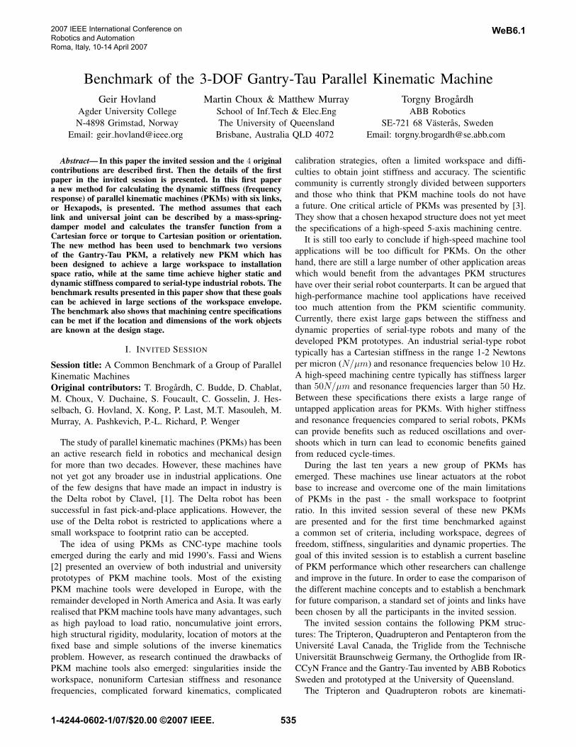
In this section a new method for calculating the frequencyresponse of any Hexapod PKM structure is presented. Fig. 1shows typical PKM links with a universal joint at either end.The flexible model of a single link in Fig. 2 assumes that
Fig. 1. Picture of typical PKM links with universal joints.
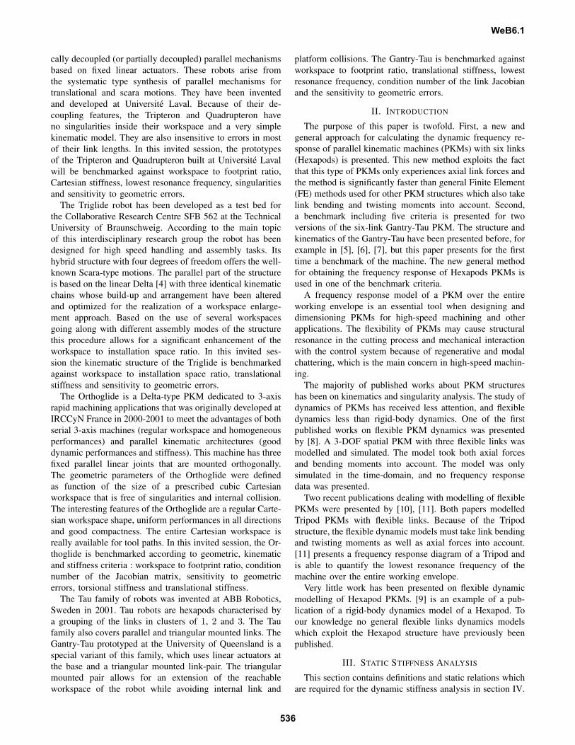
Fig. 2. Flexible link model.
the actuator is rigid and stationary as modelled by the fixedreference at the left-hand side of Fig. 2. For an accuratemodelling of a link a number of serially connected massesand springs can be used. However, since usually a link isdesigned in such a way that the stiffness of the joint is muchlower than the stiffness of the link a model as in Fig 2 willbe a very good approximation.
The parameters kj and damper zj represent the flexibilityin the universal joint. The mass mj is the total weight ofthe joint. In Fig. 2 only half of the joint mass is used, as itis assumed that one half of the joint is rigidly attached tothe stationary actuator. The mass ma is the total weight ofthe link between the two universal joints. The two halves ofthe link weight are lumped together with the joint masses.The parameters ka and za represent the link flexibility. Theparameter m2 represent the platform weight.
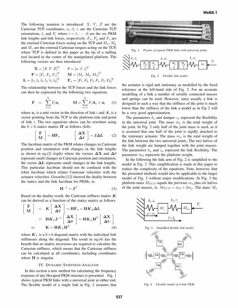
In the following the link arm of Fig. 2 is simplified to themodel in Fig. 3. This simplification is made in this paper toreduce the complexity of the equations. Note, however, thatthe presented methods would also be applicable to the largermodel of Fig. 2 without major modifications. In Fig. 3 theplatform mass MTCP equals the previous m2 plus six halvesof the joint masses, ie. MTCP = m2 + 3mj . The mass Ma
Fig. 3. Simplified flexible link model.
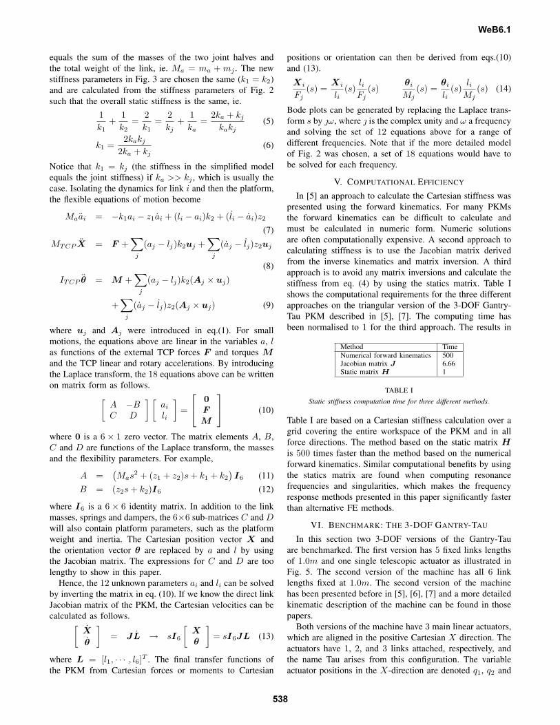
Fig. 4. Flexible model of 6-link PKM.
WeB6.1
537
equals the sum of the masses of the two joint halves andthe total weight of the link, ie. Ma = ma + mj . The newstiffness parameters in Fig. 3 are chosen the same (k1 = k2)and are calculated from the stiffness parameters of Fig. 2such that the overall static stiffness is the same, ie.
1k1
+1k2
=2k1
=2kj
+1ka
=2ka + kj
kakj(5)
k1 =2kakj
2ka + kj(6)
Notice that k1 = kj (the stiffness in the simplified modelequals the joint stiffness) if ka >> kj , which is usually thecase. Isolating the dynamics for link i and then the platform,the flexible equations of motion become
Maai = −k1ai − z1ai + (li − ai)k2 + (li − ai)z2
(7)
MTCP X = F +∑
j
(aj − lj)k2uj +∑
j
(aj − lj)z2uj
(8)
ITCP θ = M +∑
j
(aj − lj)k2(Aj × uj)
+∑
j
(aj − lj)z2(Aj × uj) (9)
where uj and Aj were introduced in eq.(1). For smallmotions, the equations above are linear in the variables a, las functions of the external TCP forces F and torques Mand the TCP linear and rotary accelerations. By introducingthe Laplace transform, the 18 equations above can be writtenon matrix form as follows.[
A −BC D
] [ai
li
]=
0FM
(10)
where 0 is a 6 × 1 zero vector. The matrix elements A, B,C and D are functions of the Laplace transform, the massesand the flexibility parameters. For example,
A =(Mas2 + (z1 + z2)s + k1 + k2
)I6 (11)
B = (z2s + k2)I6 (12)
where I6 is a 6 × 6 identity matrix. In addition to the linkmasses, springs and dampers, the 6×6 sub-matrices C and Dwill also contain platform parameters, such as the platformweight and inertia. The Cartesian position vector X andthe orientation vector θ are replaced by a and l by usingthe Jacobian matrix. The expressions for C and D are toolengthy to show in this paper.
Hence, the 12 unknown parameters ai and li can be solvedby inverting the matrix in eq. (10). If we know the direct linkJacobian matrix of the PKM, the Cartesian velocities can becalculated as follows.[
X
θ
]= JL → sI6
[Xθ
]= sI6JL (13)
where L = [l1, · · · , l6]T . The final transfer functions ofthe PKM from Cartesian forces or moments to Cartesian
positions or orientation can then be derived from eqs.(10)and (13).
Xi
Fj(s) =
Xi
li(s)
liFj
(s)θi
Mj(s) =
θi
li(s)
liMj
(s) (14)
Bode plots can be generated by replacing the Laplace trans-form s by ω, where is the complex unity and ω a frequencyand solving the set of 12 equations above for a range ofdifferent frequencies. Note that if the more detailed modelof Fig. 2 was chosen, a set of 18 equations would have tobe solved for each frequency.
V. COMPUTATIONAL EFFICIENCY
In [5] an approach to calculate the Cartesian stiffness waspresented using the forward kinematics. For many PKMsthe forward kinematics can be difficult to calculate andmust be calculated in numeric form. Numeric solutionsare often computationally expensive. A second approach tocalculating stiffness is to use the Jacobian matrix derivedfrom the inverse kinematics and matrix inversion. A thirdapproach is to avoid any matrix inversions and calculate thestiffness from eq. (4) by using the statics matrix. Table Ishows the computational requirements for the three differentapproaches on the triangular version of the 3-DOF Gantry-Tau PKM described in [5], [7]. The computing time hasbeen normalised to 1 for the third approach. The results in
Method TimeNumerical forward kinematics 500Jacobian matrix J 6.66Static matrix H 1
TABLE IStatic stiffness computation time for three different methods.
Table I are based on a Cartesian stiffness calculation over agrid covering the entire workspace of the PKM and in allforce directions. The method based on the static matrix His 500 times faster than the method based on the numericalforward kinematics. Similar computational benefits by usingthe statics matrix are found when computing resonancefrequencies and singularities, which makes the frequencyresponse methods presented in this paper significantly fasterthan alternative FE methods.
VI. BENCHMARK: THE 3-DOF GANTRY-TAU
In this section two 3-DOF versions of the Gantry-Tauare benchmarked. The first version has 5 fixed links lengthsof 1.0m and one single telescopic actuator as illustrated inFig. 5. The second version of the machine has all 6 linklengths fixed at 1.0m. The second version of the machinehas been presented before in [5], [6], [7] and a more detailedkinematic description of the machine can be found in thosepapers.
Both versions of the machine have 3 main linear actuators,which are aligned in the positive Cartesian X direction. Theactuators have 1, 2, and 3 links attached, respectively, andthe name Tau arises from this configuration. The variableactuator positions in the X-direction are denoted q1, q2 and
WeB6.1
538
q3 and have lower and upper bounds at 0 and 2.2m. The Yand Z coordinates of the actuators are fixed and are givenby: Y1 = −Q, Z1 = Q, Y2 = 0, Z2 = 2Q, Y3 = 0 andZ3 = 0, where Q = 0.5m.
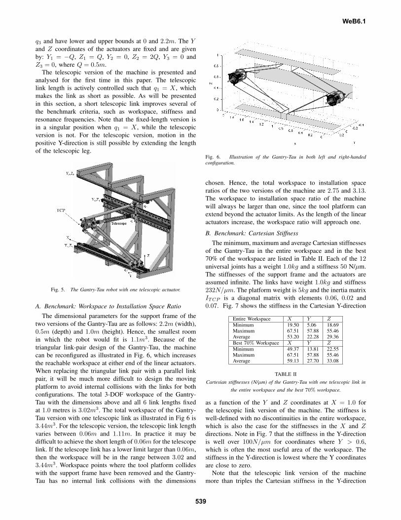
The telescopic version of the machine is presented andanalysed for the first time in this paper. The telescopiclink length is actively controlled such that q1 = X , whichmakes the link as short as possible. As will be presentedin this section, a short telescopic link improves several ofthe benchmark criteria, such as workspace, stiffness andresonance frequencies. Note that the fixed-length version isin a singular position when q1 = X , while the telescopicversion is not. For the telescopic version, motion in thepositive Y-direction is still possible by extending the lengthof the telescopic leg.
Fig. 5. The Gantry-Tau robot with one telescopic actuator.
A. Benchmark: Workspace to Installation Space RatioThe dimensional parameters for the support frame of the
two versions of the Gantry-Tau are as follows: 2.2m (width),0.5m (depth) and 1.0m (height). Hence, the smallest roomin which the robot would fit is 1.1m3. Because of thetriangular link-pair design of the Gantry-Tau, the machinecan be reconfigured as illustrated in Fig. 6, which increasesthe reachable workspace at either end of the linear actuators.When replacing the triangular link pair with a parallel linkpair, it will be much more difficult to design the movingplatform to avoid internal collisions with the links for bothconfigurations. The total 3-DOF workspace of the Gantry-Tau with the dimensions above and all 6 link lengths fixedat 1.0 metres is 3.02m3. The total workspace of the Gantry-Tau version with one telescopic link as illustrated in Fig 6 is3.44m3. For the telescopic version, the telescopic link lengthvaries between 0.06m and 1.11m. In practice it may bedifficult to achieve the short length of 0.06m for the telescopelink. If the telescope link has a lower limit larger than 0.06m,then the workspace will be in the range between 3.02 and3.44m3. Workspace points where the tool platform collideswith the support frame have been removed and the Gantry-Tau has no internal link collisions with the dimensions
Fig. 6. Illustration of the Gantry-Tau in both left and right-handedconfiguration.
chosen. Hence, the total workspace to installation spaceratios of the two versions of the machine are 2.75 and 3.13.The workspace to installation space ratio of the machinewill always be larger than one, since the tool platform canextend beyond the actuator limits. As the length of the linearactuators increase, the workspace ratio will approach one.
B. Benchmark: Cartesian StiffnessThe minimum, maximum and average Cartesian stiffnesses
of the Gantry-Tau in the entire workspace and in the best70% of the workspace are listed in Table II. Each of the 12universal joints has a weight 1.0kg and a stiffness 50 N/µm.The stiffnesses of the support frame and the actuators areassumed infinite. The links have weight 1.0kg and stiffness232N/µm. The platform weight is 5kg and the inertia matrixITCP is a diagonal matrix with elements 0.06, 0.02 and0.07. Fig. 7 shows the stiffness in the Cartesian Y-direction
Entire Workspace X Y ZMinimum 19.50 5.06 18.69Maximum 67.51 57.88 55.46Average 53.20 22.28 29.36Best 70% Workspace X Y ZMinimum 49.37 13.81 22.55Maximum 67.51 57.88 55.46Average 59.13 27.70 33.08
TABLE IICartesian stiffnesses (N/µm) of the Gantry-Tau with one telescopic link in
the entire workspace and the best 70% workspace.
as a function of the Y and Z coordinates at X = 1.0 forthe telescopic link version of the machine. The stiffness iswell-defined with no discontinuities in the entire workspace,which is also the case for the stiffnesses in the X and Zdirections. Note in Fig. 7 that the stiffness in the Y-directionis well over 100N/µm for coordinates where Y > 0.6,which is often the most useful area of the workspace. Thestiffness in the Y-direction is lowest where the Y coordinatesare close to zero.
Note that the telescopic link version of the machinemore than triples the Cartesian stiffness in the Y-direction
WeB6.1
539
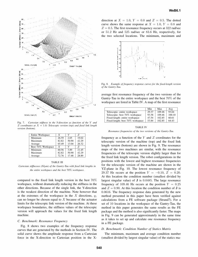
Fig. 7. Cartesian stiffness in the Y-direction as function of the Y andZ coordinates at X = 1.0: Telescopic version (top) and fixed link lengthversion (bottom).
Entire Workspace X Y ZMinimum 26.59 2.05 19.02Maximum 82.82 50.90 42.29Average 65.49 13.04 26.32Best 70% Workspace X Y ZMinimum 60.56 3.89 21.45Maximum 82.82 50.90 42.29Average 72.76 17.48 28.89
TABLE IIICartesian stiffnesses (N/µm) of the Gantry-Tau with fixed link lengths in
the entire workspace and the best 70% workspace.
compared to the fixed link length version in the best 70%workspace, without dramatically reducing the stiffness in theother directions. Because of the single link, the Y-directionis the weakest direction of the machine. Note however thatat the extremes of the workspace in the X directions, q1
can no longer be chosen equal to X because of the actuatorlimits for the telescopic link version of the machine. At theseworkspace boundaries, the stiffness values of the telescopicversion will approach the values for the fixed link lengthmachine.
C. Benchmark: Resonance Frequency
Fig. 8 shows two examples of the frequency responsecurves that are generated by the methods in Section IV. Thesolid curve shows the amplitude response from a Cartesianforce in the X-direction to Cartesian position in the X-
direction at X = 1.0, Y = 0.0 and Z = 0.5. The dottedcurve shows the same response at X = 1.0, Y = 0.8 andZ = 0.5. The first resonance frequency occurs at 322 rad/secor 51.2 Hz and 525 rad/sec or 83.6 Hz, respectively, forthe two selected locations. The minimum, maximum and
Fig. 8. Example of frequency response curves for the fixed-length versionof the Gantry-Tau.
average first resonance frequency of the two versions of theGantry-Tau in the entire workspace and the best 70% of theworkspace are listed in Table IV. A map of the first resonance
Min Max AvgTelescopic: entire workspace 29.37 109.46 93.64Telescopic: best 70% workspace 93.58 109.46 100.10Fixed-length: entire workspace 47.54 102.85 60.61Fixed-length: best 70% workspace 53.84 102.85 64.43
TABLE IVResonance frequencies of the two versions of the Gantry-Tau.
frequency as a function of the Y and Z coordinates for thetelescopic version of the machine (top) and the fixed linklength version (bottom) are shown in Fig. 9. The resonancemaps of the two machines are similar, with the resonancefrequencies of the telescopic version slightly larger than forthe fixed link length version. The robot configurations in thepositions with the lowest and highest resonance frequenciesfor the telescopic version of the machine are shown in theYZ-plane in Fig. 10. The lowest resonance frequency of29.37 Hz occurs at the position Y = −0.10, Z = 0.20.At this location the condition number (smallest divided bylargest singular value) of J is 0.0485. The large resonancefrequency of 109.46 Hz occurs at the position Y = 0.25and Z = 0.90. At this location the condition number of J is0.0616. The frequency response data generated by the newmethod presented in this paper have been verified againstcalculations from a FE software package (Strand7). For aset of 10 locations in the workspace of the Gantry-Tau, themethod in this paper generates the same results as the FEpackage and the method is also significantly faster. The mapsin Fig. 9 can be generated approximately in the same timeas it takes to set up and calculate one resonance frequencyin a FE package.
D. Benchmark: Condition Number of Statics Matrix
The minimum, maximum and average condition number(smallest divided by largest singular value) of the statics ma-
WeB6.1
540
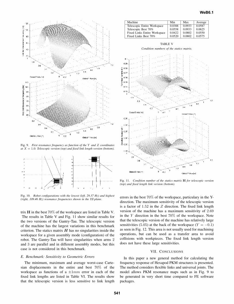
Fig. 9. First resonance frequency as function of the Y and Z coordinatesat X = 1.0: Telescopic version (top) and fixed link length version (bottom).
Fig. 10. Robot configurations with the lowest (left, 29.37 Hz) and highest(right, 109.46 Hz) resonance frequencies shown in the YZ-plane.
trix H in the best 70% of the workspace are listed in Table V.The results in Table V and Fig. 11 show similar results for
the two versions of the Gantry-Tau. The telescopic versionof the machine has the largest variations in this benchmarkcriterion. The statics matrix H has no singularities inside theworkspace for a given assembly mode (configuration) of therobot. The Gantry-Tau will have singularities when arms 2and 3 are parallel and in different assembly modes, but thiscase is not considered in this benchmark.
E. Benchmark: Sensitivity to Geometric Errors
The minimum, maximum and average worst-case Carte-sian displacements in the entire and best 70% of theworkspace as functions of a ±1mm error in each of thefixed link lengths are listed in Table VI. The results showthat the telescopic version is less sensitive to link length
Machine Min Max AverageTelescopic Entire Workspace 0.0388 0.0933 0.0587Telescopic Best 70% 0.0558 0.0933 0.0625Fixed Links Entire Workspace 0.0422 0.0802 0.0550Fixed Links Best 70% 0.0520 0.0802 0.0575
TABLE VCondition numbers of the statics matrix.
Fig. 11. Condition number of the statics matrix H for telescopic version(top) and fixed length link version (bottom).
errors in the best 70% of the workspace, particulary in the Y-direction. The maximum sensitivity of the telescopic versionis a factor of 1.52 in the Z direction. The fixed link lengthversion of the machine has a maximum sensitivity of 2.69in the Y direction in the best 70% of the workspace. Notethat the telescopic version of the machine has relatively largesensitivities (5.05) at the back of the workspace (Y = −0.1)as seen in Fig. 12. This area is not usually used for machiningoperations, but can be used as a transfer area to avoidcollisions with workpieces. The fixed link length versiondoes not have these large sensitivities.
VII. CONCLUSIONS
In this paper a new general method for calculating thefrequency response of Hexapod PKM structures is presented.The method considers flexible links and universal joints. Themodel allows PKM resonance maps such as in Fig. 9 tobe generated in very short time compared to FE softwarepackages.
WeB6.1
541
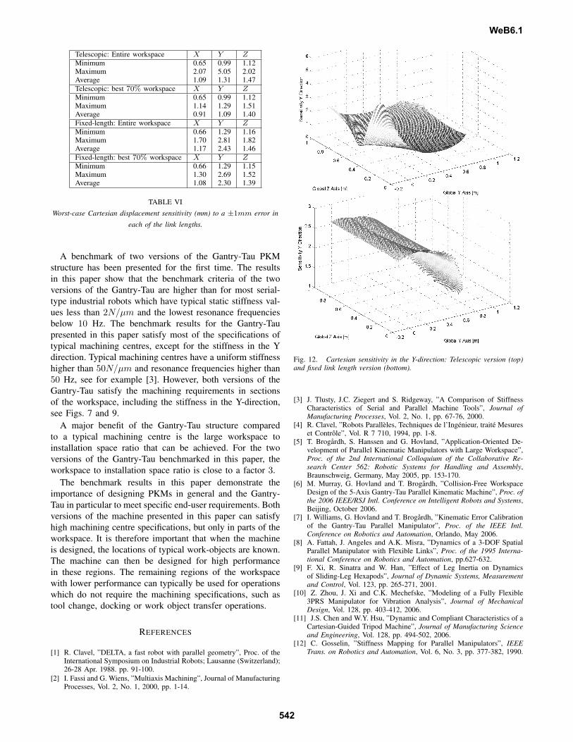
Telescopic: Entire workspace X Y ZMinimum 0.65 0.99 1.12Maximum 2.07 5.05 2.02Average 1.09 1.31 1.47Telescopic: best 70% workspace X Y ZMinimum 0.65 0.99 1.12Maximum 1.14 1.29 1.51Average 0.91 1.09 1.40Fixed-length: Entire workspace X Y ZMinimum 0.66 1.29 1.16Maximum 1.70 2.81 1.82Average 1.17 2.43 1.46Fixed-length: best 70% workspace X Y ZMinimum 0.66 1.29 1.15Maximum 1.30 2.69 1.52Average 1.08 2.30 1.39
TABLE VIWorst-case Cartesian displacement sensitivity (mm) to a ±1mm error in
each of the link lengths.
A benchmark of two versions of the Gantry-Tau PKMstructure has been presented for the first time. The resultsin this paper show that the benchmark criteria of the twoversions of the Gantry-Tau are higher than for most serial-type industrial robots which have typical static stiffness val-ues less than 2N/µm and the lowest resonance frequenciesbelow 10 Hz. The benchmark results for the Gantry-Taupresented in this paper satisfy most of the specifications oftypical machining centres, except for the stiffness in the Ydirection. Typical machining centres have a uniform stiffnesshigher than 50N/µm and resonance frequencies higher than50 Hz, see for example [3]. However, both versions of theGantry-Tau satisfy the machining requirements in sectionsof the workspace, including the stiffness in the Y-direction,see Figs. 7 and 9.
A major benefit of the Gantry-Tau structure comparedto a typical machining centre is the large workspace toinstallation space ratio that can be achieved. For the twoversions of the Gantry-Tau benchmarked in this paper, theworkspace to installation space ratio is close to a factor 3.
The benchmark results in this paper demonstrate theimportance of designing PKMs in general and the Gantry-Tau in particular to meet specific end-user requirements. Bothversions of the machine presented in this paper can satisfyhigh machining centre specifications, but only in parts of theworkspace. It is therefore important that when the machineis designed, the locations of typical work-objects are known.The machine can then be designed for high performancein these regions. The remaining regions of the workspacewith lower performance can typically be used for operationswhich do not require the machining specifications, such astool change, docking or work object transfer operations.
REFERENCES
[1] R. Clavel, ”DELTA, a fast robot with parallel geometry”, Proc. of theInternational Symposium on Industrial Robots; Lausanne (Switzerland);26-28 Apr. 1988. pp. 91-100.
[2] I. Fassi and G. Wiens, ”Multiaxis Machining”, Journal of ManufacturingProcesses, Vol. 2, No. 1, 2000, pp. 1-14.
Fig. 12. Cartesian sensitivity in the Y-direction: Telescopic version (top)and fixed link length version (bottom).
[3] J. Tlusty, J.C. Ziegert and S. Ridgeway, ”A Comparison of StiffnessCharacteristics of Serial and Parallel Machine Tools”, Journal ofManufacturing Processes, Vol. 2, No. 1, pp. 67-76, 2000.
[4] R. Clavel, ”Robots Paralleles, Techniques de l’Ingenieur, traite Mesureset Controle”, Vol. R 7 710, 1994, pp. 1-8.
[5] T. Brogardh, S. Hanssen and G. Hovland, ”Application-Oriented De-velopment of Parallel Kinematic Manipulators with Large Workspace”,Proc. of the 2nd International Colloquium of the Collaborative Re-search Center 562: Robotic Systems for Handling and Assembly,Braunschweig, Germany, May 2005, pp. 153-170.
[6] M. Murray, G. Hovland and T. Brogardh, ”Collision-Free WorkspaceDesign of the 5-Axis Gantry-Tau Parallel Kinematic Machine”, Proc. ofthe 2006 IEEE/RSJ Intl. Conference on Intelligent Robots and Systems,Beijing, October 2006.
[7] I. Williams, G. Hovland and T. Brogardh, ”Kinematic Error Calibrationof the Gantry-Tau Parallel Manipulator”, Proc. of the IEEE Intl.Conference on Robotics and Automation, Orlando, May 2006.
[8] A. Fattah, J. Angeles and A.K. Misra, ”Dynamics of a 3-DOF SpatialParallel Manipulator with Flexible Links”, Proc. of the 1995 Interna-tional Conference on Robotics and Automation, pp.627-632.
[9] F. Xi, R. Sinatra and W. Han, ”Effect of Leg Inertia on Dynamicsof Sliding-Leg Hexapods”, Journal of Dynamic Systems, Measurementand Control, Vol. 123, pp. 265-271, 2001.
[10] Z. Zhou, J. Xi and C.K. Mechefske, ”Modeling of a Fully Flexible3PRS Manipulator for Vibration Analysis”, Journal of MechanicalDesign, Vol. 128, pp. 403-412, 2006.
[11] J.S. Chen and W.Y. Hsu, ”Dynamic and Compliant Characteristics of aCartesian-Guided Tripod Machine”, Journal of Manufacturing Scienceand Engineering, Vol. 128, pp. 494-502, 2006.
[12] C. Gosselin, ”Stiffness Mapping for Parallel Manipulators”, IEEETrans. on Robotics and Automation, Vol. 6, No. 3, pp. 377-382, 1990.
WeB6.1
542


![Kinematic Analysis of A 3-DOF Parallel Mechanism for ... · dance with the Kutzbach-Gruebler criterion [2], λ=6, n=8, ... Kinematic Analysis of A 3-DOF Parallel Mechanism for Milling](https://img.pdfslide.us/doc/110x75/5b1c01a67f8b9a46258f3522/kinematic-analysis-of-a-3-dof-parallel-mechanism-for-dance-with-the-kutzbach-gruebler.jpg)