Embed Size (px)
Citation preview

115 ,I2 MAR 04 INTRODUCTION ZUEFPEsENAPPROACH CHART LEGENDAIRPORT CHART FORMAT
The airport chart is typically printed on the reverse side of the first approach chart in the ser¡es. At many airports,espec¡ally large terrninals, the airport chart will precede the first approach chart and contain an enlarged diagram.Airport charts depict commun¡cations frequencies as well as runway, taxiway and ramp information. Additionally,approach and runway lighting, declared distances, IFR and obstacle depárture procedures, and take-off and alternateminimums are shown. ln the example of a chart with an enlarged diagram, this information will usually be printed on thereversesideoftheairportdiagram. Separatechartsmaybeincludedthatdepictdetailedrampareasandparkingpos¡tions as well as low visibility tax¡ [outes.
HEADING
Airport, Ramp and Taxiway chartsAt the top of page are the location and a¡rport names, the airport's elevation and latitude and longitude, the JeppesenNavData (ICAO) and IATA ¡dentif¡ers, and the revision date.
ATWN/TWN.AApt Elev 1575'F-4N¿0 00.0 wl04 5t.0 ,r
¿.r t¡JEPPEsElu o=*lt¡ytOwN. W0RLD\onr¡ @..--O O+ANYTóWN, INTL
O Jeppesen NavData (ICAO) and IATA identifiers. O Revison date.
O A¡rpod elevation. O lndex (page) number (same as approachchart when the airport is pr¡nted on the
lO Geograph¡clatitudeandlongitudecoord¡nates¡n reverses¡deofthefirstapproachchart).degrees, minutes, and tenths of m¡nutes, representingthe location ofthe a¡rport reference point (ARP) when O Geographic location name.an ARP symbol is shown. On charts where the ARP isnot shown, coordinates represent the airport location O A¡rport name.as provided by the controlling authority.
COMMUNICATIONS
Communications for departure are l¡sted ¡n order of normal use.q
ATIS {ASO5
127.75Ground
121.9D.AT¡S
PDCTWIP l3 t .97
CTAF
120.100lo-i800 l8t'-3ó0'r2ó.55 125.5
UNICOM122.95
NAl,lED Cenler (R)
120.45
/O VOR test trequency. (L¡mited) preceding VOT ¡ndicates O An aster¡sk (-) indicates part-time
the test signal can only be received at designated operat¡on.posit¡ons on the airport
o Radar is ava¡rable
@ JÉPPESEN SANDERSON, INC., 1990, 2004, ALL RIGHfS RESERVED
NEW FORIüAT 6 Io DEc a9 INTRODUCTION ¡UEPF¡ESEN
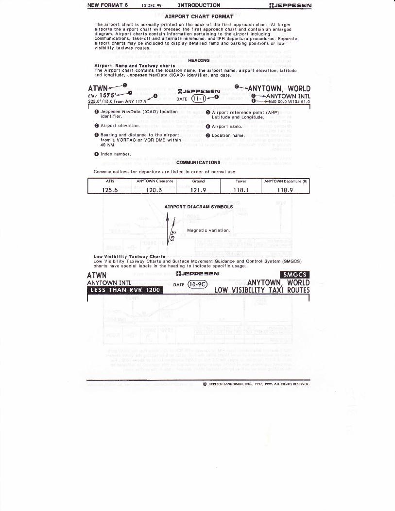
A¡RPORT CHART FORMAT
Th€ e¡rport chart ls normally prlnl€d on the back of the lirst approach chart. At largera¡rports the alrport chart w¡ll pr€c€€d lhe f¡rst approach chart and conte¡n an enlargedd¡agram. A¡rport chafts contain informalion perta¡ning to the airporl ¡ncludingcommun¡cations, take-off and alternalo minimums, and IFR departure procsdures. Separatea¡rpo.t oharts may be included to display dola¡led tamp and parking positions or lowvis¡bil¡ty taxiway roules.
HEAOINGAlrporl, R¡mp rnd Tarlury chrrtrThe Alrporl chart conieins the locat¡on name, the airport namo, eirport elevatlon, lat¡lud€and longitude, Jeppesen NavData (ICAO) ldentlfior, and dele.
O Jeppesen Navoata (!CAO) locatlonidentil¡er.
@ lirport elevatlon.
@ Bearing and disl€noe to the airportfrom a VORTAC or VOR DME within40 NM.
O Index number.
ATWNANYTOWN INTT ANYTOWN, WORLD
ATWN*-..--o^ zuEPpEsErv o-ANyTOWN, WORLDi.liiils'-,=o Zl¡eeeesr22s.0./tr.orromANy ,rr.r} oerr (Til-o SSTrtlr?#lijlJl
ooilltuNrcATroNs
Communications for departure are listed ln order of normal use.
At ¡5
125.6
uwN qt@tcnce
t20.3
Ordnd
121-9
Towcr
llR.tANYTOWN O€parrure (R)
I t8.9
A¡RPORT DIAGRAT' SYiIBOLS
Megnetic variat¡on,
Low Vlrlbll¡ly Texlwlt ChrrlrLow Vis¡bility Taxiway Charts and Surlace Movemenl Guidance and Control System (SMGCS)charts have special lab6ls in the hoading lo ¡nd¡cate specific usage.
3l¡ee¡¡eseruoot, (IE)
O Airport refer€noe point (ARP)Latitude and Longitude.
@ Alrport name.
@ Location name.
@ JEPPESEN sANDEisoN, tNc., 1997, 1999, Ar.r. RrcHrs RESERVED

JEFFIEE¡EI\I ¡NTRODUCTION II JUt 97 117
APPROACH CHART LEGENDA¡RPORT PLAN VIEW
sYttBoLsPhys¡cal feature symbols used on lhe airporl
^ Runway number is magnetic
- (27) unless followed by T for lrue
¡n the far north-
Runway number and (whén
- @ [li#i ¿l1srilii'riiii;,.
==@ ifiB'¡ff.il"1"tins area' or
-
Paved runway
-¡
Unpaved runway
@ Pierced stoel Plank¡ng (PSP)
. Seaplane operating area or
=,=== water runway. Dash lines in-dicate operating area.
ffdf Displacedthreshold
I¡r Designated stoo bar or------- designated hold¡ng position.
rrrrtF Category IIllII holding posit¡on.
{pg, f,:Bi:::I l,nn:'..h;ñ'"no'nn 'o
É unidirectional Arrester Gear
-- Bidirectional Arrester Gear
+ Jet Barrier
Closed runway. Temporary
-t
closed runways will retainlength and runway numbers.
-l
Stopway or overrun
==== Area undsr construction
I Flunwav shoulder lwhen
-
readily noticeable)
No differentiation between types of surface torramps, tax¡ways, closed runways, closed taxi-ways, runway shoulders, and areas other thanrunways. Stopways and overruns are shownregardless of surface, with the length, whenknown. Stopway and overrun lengths are notincluded ¡n runway lengths.
ADDTTTONAL INFORMATION
Runway end elsvations are shown on the air-port diagram ¡f source is available.
Approach lights and beacons are the onlyl¡ght¡ng symbolized on the airport diagram.Approach l¡ghts are normally shown to scale ¡n
a recognizable form. For approach light sym-bols see page 121.
A representative select¡on of relerence po¡ntsknown to Jeppesen is depicted. The slevationof reféronce points dspicted ¡s above mean sealevel (MSL).
Latitude and longitude ticks at lenths of a min'ute ¡nterval are charted around most planviewneallines.
chart are illustrated below.
hü raxiway and apron
x xxxx Permanently Closed taxiway
C Authorized Landing Area
A Helicopter landing pad
/+\ Airport Reference Point. Off-tl/ runway. Center of cross posi-ARP tioned at exact locat¡on.
ARp Airport Reference Point. Lo-{ cated on runway centerline.
-
Arrow pornrs Io exacl rocalron.
I-7F'IE RVR measuring site, may havev v v idsntifying letter or number.
Ai roort/Aerodrome/\E, Ide;t¡fication beacon.
On-airport navaid - VOR, NDBor LCTR (locators, other thanvux
- o'-" locators associated with ILS).Depicted on charts dated onand after 5 FEB 93.
. Railroad
Pole line
Y Lighted Pole
Road
: Bluffcr,J
-.1.r.,,- l lrees
F Cone
v Tee
a Tetrahedron
I t f Buildings
N\t Larse bu¡ldins
teer 0 1000 2000 3000 4000 5000ffia,++{++¡'|-tMetsrs 0 500 1000 1500
Bar Scale
O JEPPESEN SANDERSoN, ¡Nc., 1991, 199?. Att R¡cHls RCSERVEo.

118 il JUt 97 INTRODUCTTON JEPPEs¡EIU
APPROACH CHART LEGENDADDITIONAL RUNWAY INFORMATION
RUNWAY AND APPROACH LIGHTSFor abbreviat¡ons used see page 119.
PILOT CONTROLLED AIRPORT LIGHT¡NG SYSTEMS
See "Pilot Controlled Lights (PCL)" in the following seclions: INTRODUCTION, Chart Gloss-ary for the Uniled States of America, AIR TRAFFIC CONTROL, Rules and Procedures for theapplicable State. Non-standard light¡ng act¡vat¡ons are spec¡fied on ind¡vidual charts.
See O above for chart¡n9 sample.
USABLE LENGTHS
The usable lengths have been determined as follows in the additional runway information.When usable runway lengths differ from those depicted in the airport planview, lengths arespec¡fied ¡n the "USABLE LENGTHS" columns. Blank columns indicate that the runway lengthdepicted ¡n the airport planview ¡s appl¡cable.
LANDING BEYOND
Threshold--When the landing length is restrictéd, thé length shown is the distance beyond thelanding threshold to the roll out end of the runway.
Glide Slope--The length shown for ILS is the d¡stance from a po¡nt abeam the glide slopetransmitter to the roll-out end of the runway. For PAR, the length shown ¡s the distancs fromthe theoretlcal gltde slope interception with the runway to the roll-out end of the runway. lfboth ILS and PAR are available, data provided is for ILS.
TAKE-OFF
When the lakeroff length is restricted, the length shown is the d¡stance beyond the point forbeginning the lake-off roll to lhe end ot the surface usable for lake-off.Stopways, ovdrruns, or clearways are not included in the above figures.
NOTE: An NA charted as Addit¡onal Runway lnformation indicatés that take-offs or land¡ngsare not aulhorized for the rwy shown.
LAND AND HOLD SHORT OPERATTONS(LAHSO)
Air Traff¡c Controllers may author¡ze operations wh¡ch ¡nclude simullaneous take-offs and 1
land¡ngs and/or simultaneous landings when a land¡ng aircraft is able and ¡s instructed bythe controller to hold-short of the inlersecting runway/taxiway or designated hold-shortpoint. Thé available land¡ng distance is shown ¡n the LAHSO D¡stance column. On chartsdated before 1 l JUL 97 the column is titled Threshold lo Intersecting Runway. r
@ JEPPESEN SANDERSoN, ¡Nc., t929, t997. Au. R¡cHTs RESERVEo.
USABI-E I.ENGTHSI-ANDING BEYOND ----+
HIRT CT HIATS SFI
ORt OVAS¡ (angle 2.,t')
QAcrivate on 122,8.
HlRt MATSR VASI-I grooved

ZUEFpESEIv INTRODUCTION II MAYOI
APPROACH CHART LEGENDTAKE-OFF AND ALTERNATE MINIMUMS
Publication oi m¡nimums does not constituté au¡hotity fot lheir use by all operalors. Each índívidualoperalor must obla¡n appropriale approval for their use,
On all formats, when the take-ofl minimums are specified ¡n terms of c€iling and visibilily,EOTH must be reported by the responsible ground unit.
TAKE.OFF iIINIIIIIUIIS, USA CHARTS
125
Standard Take-off lAinimums in the USA: lnestandard take-off minimums is nvn50o.l for1 & 2 Eng. aircraft and nva24o"Yz for 3 & 4Eng. aircraft.
Runway Visual Range (RVR) is to be usedinstead of reported v¡s¡bility for operat¡ngon any runway for which RVR is report€d.
Take-ott reslrictions, including ceiling andvisibility requif€ments, and obstacle deP-arture procedures, apply to FAR 121, 129and 135 operalors.
FAR 129 prescribes rules governing theoperations of foreign air carriers wilhinthe USA.
A, Lowet-than-Stánda¡d lake-oif Minimums:On runways where standard minimums areaulhorized, and lowEr-than-standardminimums are not denisd, the followingminimums are also author¡zed for operatorsunder FAR Part 121, and 129. Such minimumgmay be authorized for those FAR 135opsralors, having gpecific author¡zat¡on inth€¡r Operat¡ons Specif ¡cations.
The Lower-than-Standarcl Minimums are:
Visibility or RVV /¡ statute mile or Touch-down Zone RVR 16, prov¡d€d at least one ofthe follow¡ng v¡sual a¡ds is ava¡lable. TheTouchdown Zone RVR report, it available, iscontrolling. The Mid RVR report may be sub-st¡tuted for the Touchdown zone RVR reportif the Touchdown Zone RVR report is notavai lable.
(1) Operative high intens¡ty runway l¡ghts(HIRL)
(2) Operative runway centerl¡ne lights (CL).
(3) Runway centsrline marking (RCLM).
(4) In circumslances when none of tho abovevisual a¡ds are availabl€, v¡sibility orRVV y1 statute mile may still be used,provided other runway markings or run-way lighting provide pilots with adequatevlsual reference to continuously identifythe teke-off surlace and maintain direct-ional control throughout the take-otf run.
B. Touchdown Zone RVR 10 (beginning oftake-off run) and Rollout RVR 10, providedall of the follow¡ng visual a¡ds and RVR squ¡p-meni ars available. The M¡d RVR may bs sub-stituted for the Touchdown Zone RVR report¡f the Touchdown Zone RVR report is notavai lable.
('l) Operative runway centerline lights (CL).
(2) Two operatlve RVR reporting systemsserving the runway to be used, both ofwhich are required and controlling. AMid RVR report may be substituted foreither a Touchdown Zone RVR report ifa Touchdown Zone report is not ava¡l-able or a Rollout RVR report if a Roll-out RVR report is not ava¡lable.
(2) Runway centerline mark¡ngs (RCLM).
(3) Operative Touchdown Zone and RolloutRVR reporting systems serving the run-way to be used, both of which are con-troll¡ng, or three RVR reporting systemsserving the runway to be used, all ofwhich are controlling. However, if oneof th6 three RVR reporting systems hasfa¡led, a take-off is authorized, providedthe remaining two RVR values are at orabove the appropriate take-off minimums.
D. Take-off Guidance System, if apPlicable.
Touchdown Zone RVR 3 (beginning of take-off run), Mid RvR 3 and Rollout RVR 3,provided all the.following aids are ava¡lable.Op€rative Touchdown Zone RVR and RolloutRVR reporting systems serv¡ng the runway tobe used, both of which are controlling, or threeRVR reporting systems serv¡ng the runway tobe usgd, all of which are controlling. Howevsrif one of the three RVR reporting systems hasfailed, a take-off is authorized, provided therema¡ning two RVR values are at or above lheappropriate take-off minimums.
(1) Operative h¡gh intensity runway lights(HIRL)
(2) Operative runway centerline lights (CL).
(3) Serviceable runway centerline markings(RCLM).
(4) Front course guidance from the localizermust be available and usód (if applicable toguidance system used).
(5) The reported crosswind comPonenl shallnot excesd l0 knots.
16) The oilot ¡n command and the second in' comrhand have completed the certificateholders approved trainlng program forthese operations.
(7) All operat¡ons us¡ng these minimums shallbg conducted to runways wh¡ch providedirect access to taxiway routing wh¡ch are€qu¡pped with op€rativo taxiway centerlinelightlng which meets U.S. or ICAO crlteriafor CAT III operations; or other taxiwayguidanc€ systems approved for theseoperat ions,
At soms airports, obstructions or other. C. Touchdown Zone RVR S (beginning offactors require lhe establishment of.higher také-off run), Mid RVR 5 a;d ño¡¡ouI RVR S,lhan standard take-off m¡nimums and/or..ob- prov¡ded all'óf the following v¡sual aids andstacle departure procedures.lo asslsl pilots hVR equipment are availablé.during the IFR climbout to the minimumenroule altitude or cruising altitude. (1) Operative runway centerl¡ne l¡ghts (CL).
O JEPPESEN SANDERSoN, tNc., 1991,2001. Al.l RIGHTS RESERVED.

126 II MAYOI INTRODUCTTON
'UEPPESENIAPPROACH CHART LEGENDTAKE-OFF AND ALTERNATE MIN¡MUMS (continued)
USA FORMAT
The title TAKE-OFF & OBSTACLE DEPARTURE PROCEDURE ¡S uSEd tO iNdiCAIE thAt bothtake-off m¡nimums and obstacle departure procedures are specif¡ed. In such cases, refer tolhe note oBSTACLE OP to the lef t and immediately below the m¡nimum columns for theprocedure.
Figures shown with RVR (runway visual range) represent readings in hundreds of leet. Thef¡guros without the RVR prefix represent vis¡bility in statute miles or fractions thereof.For example: nvn50orl means 5000 feet RVR or one statute mile visibility:eva24o,Yz means 2400 feet RVR or one-half statute m¡le v¡sib¡l¡ty.lndividual runway columns are shown whenever m¡n¡mums are not the sams for all runwaysThe best opportunity runway is shown at the fer left. Wilhin eech runway column, all con-dilions are spec¡fiecl, and'i.nimums are positioned in ascending order, left to right.Columns are not establ¡shed solely to identify runways with and without RVR when allother condit¡ons are the same.
Altitudes listed in climb gradient requirements or for obstacl6 departure proceduros areabove Mean Sea Level (MSL). Ce¡ling spec¡f¡ed for Take-off m¡nimums or Alternate minimumsare heights Above Airport Level (AAL).
O JEPPESEN SANDERSoN, lNc., 1991, 2001. Att RIGHIS RESERVED.
"Adequate V¡s Ref" is shown as a rem¡nder that at least oneof the following visual aids must be available. The TouchdownZoné RVR réport, if available, is controlling. The M¡d RVR re-port may be substituted for the Touchdown Zone RVR reportif lhe Touchdown Zone RVR is not available.(1) Operat¡ve high intensity runway lights (HIRL).(2) Operal¡ve runway centerline lights (CL).(3) Runway centerline marking (RCLM).(4) ln circumstancss when none of the above visual aids are
available, visibility or RVV y¡ statute mile may still béused, prov¡ded other runway markings or runway light¡ngprovide pilots with adequate visual reference to continuous-ly identify the take-off surface and mainlain directional
I
Fppll""bl" t" FAR 121 and 129 operators. I| ¡bbl¡caure to FAR 135 operators having I /I specific authorization ¡n their operations I /I specifications. I /tt/I Operative Touchdown Zone and Rollout I tI RVR reporting systems serving the run- I / /I way to be used, both of wh¡ch are con- I / /I trolling, or three RVR reporting systems I / /I serving lhe runway to be used, all of I / /I which are controll¡ng. However, ¡f one I 1 /I of the three RVR reporting systems has I / /I taiteo, a take-off is authoiized provided I / /I the remaining two RVR values are at or I / I
ISTD denotes standardItake-of f min¡mums forlrnR lzr, 123, 1zs,129land 135 ooerators./Stanoaro is nvn50o.lllfor 1 & 2 Ens.lleva24",fzfor3&4
/ I ens.
I-I I The obstacle DP for/ | runw"ys 29LlR require/ | lwnen the weather is/ | below 1000' ceiling-7/ I m¡les) a climb to 1800'/ I tr¡sl- on runwav head-I /ling before iniiiatingl llaturn.'t-/ I to ue el¡gible for the/ | minimum shown in the/ lcolumns below, a climb/ | gradient of at least
I 290'lNM is roquiredI until reaching 1000' MSL.
I If unaOte to meot climbI requirement, 300' ceil¡ng-I RVR 50 or 1 mile apply.
./ Restrictions in this/ column, if any, apply
to all opsrators.Approaches \w¡rh \ LOC, VOR, etc.electronic \approaches.glide slope. \ \
above the iate take-of f minimums.
/\ TAKE-oFF & oBSTACLEIEPARTIdRE PI DURE
ffi\ Rwys I lR, 29t 4, ltt,22,\29RJ (Rwy llR) \lApproved GuidanceI Svstem Redu¡réd
ct & Rcr.r
\vnvnoul, othetwo req.
/Adequate
/STD
With Mlm climb o''zso'ltúvl ro looo' \
OthercL & RctM
any RVR out, othertwo r€ouired
Vis Ref ldequfiev¡s úl STD
l&2Eng
roz nvn 5MId RVR 3
Rollout RVR 3
TDZ ERVR JMid ERVR J
Rol lout ERVR J
nvn lóorf t
nv1504,1 ,uJ,u
"1"
RVR 50o. I 500-
nvn 50o, I
4B 600-2 800-2
3&,1Eñg
/nvn 24orfz
RVR 24", Yt
cD
OBSTACIE DP: Rwys 291 & 29R when weather is fbelow 1000-7 northbound depariures (29óo clockwiseI ló") climb rwy heading to 1800' before turning.

¡uEPFEsElv INTRoDUCTIoN I I MAY 0l 127
APPROACH CHART LEGEND
TAKE.OFF AND ALTERNATE I,ITNII'UMS (CONtINUEd}
TAKE-OFF lllN¡ilUlls, WoRLDWIDE CHARTSPublication oÍ minimums does not constilule aulhority for ¡heir use by all oPeralors, Each individualoperelü musl obla¡n aPPrcPriale approval for lheir use'
On all formats, when the take-off m¡nimums are specified ¡n tsrms of ceiling and visibility, bothvaluEs must be reported by the responsible ground unit.The taks-off mintmums publ¡shed under the title AtR CARRIER ars based on Joint Av¡ation RsgulationOperat¡ons Subpart E. On charts datsd prior to 12 Nov 99, th€ take-off min¡mums are Publ¡shsd basedon ICAO/ECAC guidance material supportsd by adopted pract¡ce.
Táke-off minimums published under the tille A¡R CARRTER (FAR 121) are based on U.S. Operat¡ons
- Specificat¡ons.
G fne application of these taks-off minimums may be limited by the obstacle env¡ronment ¡n lhe take-I otf and departure area. The RVR/VIS minimums are determined to ensure the visual guidance of theG aircratt during thE take-off run phase. Ths subsequent clearance of obstacles is the responsi-
bility of the operator.
RVR and visiblity values arg shown in msasur¡ng units as reportsd by the governing agency.
The tifle TAKE-OFF & DEPARTURE PROCEDURE is used to ind¡cate that both take-off min¡mumsand departure procedures are specified. tn such cases, refer to the note DEPARTURE PROCE-DURE to the left and immediately below the minimum colums for the procedure.
WORTDWIDE FORMAT FOR NON.FAA OR JAA MEMBERSTATES ON CHARTS DATED ON OR AFTER II MAY 01.
TAKI .OFF
ALVP must be
Rwys 07, 08,25,25
pr tat
IR CARRIER
ln Force I
Att Rwys I
RctM (oAY olv)lALL Rwys
RCLM (DAY only)a¡ Rt
AIR CARRIER (FAR I2Rwys 07, 08,25,26
I
CL A RCLM I
rnv RVR out. I Ad"ou.t.athár two re;. I Vi3 rel
)
Rwys02r.. 20R
AdeoualeVis ref
lIc
200n (t50n) 250m
t 100m
2
Eng
3&,1Eng
TDZ RVR '5OM
Mid RVR t50m
Ioll out RVR ,50,
RVR 500n
vIS 100m
\RVR 500m
vIS l00m
D 250m 1200m) '- tubn -.'Thess min¡mums are providod for operators notapply¡ng take-off min¡mums as specified und€rAir Carrier (FAR 121). RVR/VIS in paren-theses apply only if TDZ RVR is supplementedby RVR reports at mid runway and/or roll-outend. The TDZ RVR can be determ¡ned by thepilot from the take-off position and isconsidered for the appl¡cat¡on of these min¡-mums. Therefore, RVR/VIS m¡nimums approp-riale to TDZ RVR may be charted, even thoughlhe RVR may not be installed. Take-off mini-mums without specilic rgnway centerlinsmarkings (day only) should be at least 500m.A Low Vis¡bility Take-off with RVR/vlS below400m requires the verilicat¡on lhat Low VisibilityProcedures (LVPS) have been establishad and arein force (all CAT II/lll approved aerodromes).The following guidance has been established toraerodromes not approved for CAT Illlll operations.
Until such time that tho concePt for LVPs isalso established for such aerodromes, lhecommander must satlsfy himsslf with A¡rTrsftic Serv¡ces, or the Aerodrome Operator,that for a Low Visibility Take-off only oneaircraft at a tim€ is on the maneuveringarea, and lhal vehicle traffic on themaneuvering area is controlled andrestr¡ctod to ths absolute m¡nimum.
Author¡zed lower-than-slandard take-off m¡n¡-mums of RVR 500m VIS r00m must b€ increassdto the standard RYR 1500m ot VIS ló00m lo( 1
& 2 eng. aircraft and lo RVRT20DotVlS 800nfor 3 & 4 eng. aircralt, unless one of the follow-¡ng v¡sual aids ¡s ava¡lablo.
"Adequate V¡s Ref" is shown as a reminder thatat least one of the following visual aids must beavailable. The Touchdown Zone RVR report, ifavailable, is controll¡ng. The Mid RVR reportmay be substituted for the Touchdown ZoneRVR report if the Touchdown Zone RVR reportis not available.(f) Operative high intsnsity runway lights
(HrRL).(2) Operatlve runway centerline lights (CL).(3) Runway cenlerllne marking (RCLM).(4) In circumstances when none of lhe abovevisual aids are available, 400m vis¡bility IRVR500m vis 400m (RVR 16 orl¡¡)l may still beused, prov¡ded other runway markings orrunway lighting Provide Pilots witñ adequatevísual reÍerence to cont¡nuously ident¡fy thetake-off surface and maintain d¡rectional con-trol throughout the take-off run.
@ JEPPESEN SANDERSoN, INc., 1989,2001. Att RIGHIS RESERVED.

128 II MAYOI INTRODUCTTON !l¡eeeeseruAPPROACH CHART LEGEND
TAKE-OFF AND ALTERNATE M¡NIMUIIS (contlnued)ALTERNATE MINIMUMS
ALTERNATE min¡mums w¡ll be charted only for individual airports when spécified by th€ country.Charted min¡mums are those specified by the country. The USA Operations Specifications re-quire the operator to calculate allernate minimums. The follow¡ng ¡s a condensed version of theapplicable Operations Spec¡f ications.
MINIMUMS FOR FII.ING AS ATTERNATE
When USA Operations Specifications are binding, the cerlificate holder is authorized to derivealternate airport weather min¡mums from the following table. In no case shall the certificat6holder us6 an altsrnate a¡rporl wsather minimum lower than any applicabls minimum derived fromthis table. In determining alternate airport wealher minimums, the certificate holder shall notuse any a¡rport which is not authorized for use as an Alternate Airport.
tln this context, a "d¡fferent" runway is any runway with a different runway number, whereas"separate" runways cannot be opposite ends ot the same runway.
@ JEPpESEN SANDERSoN, tNc., t989, 2oor. Ail- RrGHts RESERVED.
APPROACH FACITITY CONFIGURATION Alternale Airport IFfCeil ing
Weaiher MinimumsVisiblility
For a¡rports with at least one operational navi-gat¡ónal fac¡l¡ty provid¡ng a stra¡ght-in non-precision approach procedure, or Category 1
precision approach, or, when appl¡cable, a cir-cl¡ng maneuver from an instrument approachpr oced ure.
Add 400 fr to the MDHor DH as applicable.
Add I SMor ló00mtothe landing m¡nimum.
For airports with at least two operational navi-gational fac¡l¡ties, each providing a straight-inapproach procedure to different, 'su¡tablerunways.For an ER-OPS Enroute Allernate Airport theseoperat¡ons spec¡fications apply for separate'su¡table runways.
Add 200 ft to theh¡gher DH or MDH ofthe two approachss
used.
Add J¡¡Si¡t or 800m tothe higher authorized
landing min¡mum ofthe two approaches
used.