Embed Size (px)
Citation preview
Installation guide
V1.0.9
JACO - Installation Guide
ii | P a g e
TABLE OF CONTENTS
ABOUT THIS DOCUMENT ....................................................................................................... 1
Symbols, definitions and acronyms .......................................................................................................... 1
General Information ................................................................................................................................ 1
DISCLAIMER ................................................................................................................................ 2
MECHANICAL INTEGRATION................................................................................................. 3
Bolt Fastening Requirements ................................................................................................................... 3
Wheelchair Interface ............................................................................................................................... 5
Main base ................................................................................................................................................ 7
Bracket system ........................................................................................................................................ 8
Mechanical Integration Assembly Validation ......................................................................................... 12
ELECTRICAL INTEGRATION ................................................................................................ 13
CONTROL INTEGRATION ..................................................................................................... 14
Kinova standard joystick ........................................................................................................................ 14
Through the wheelchair controller ......................................................................................................... 15
CONTACT SUPPORT .............................................................................................................. 17
APPENDIX 1: MECHANICAL INTEGRATION – PARTS DESCRIPTION ..................... 18
APPENDIX 2: ASSEMBLING TWO SQUARE EXTRUSION ............................................ 22
APPENDIX 3: CABLE PROVIDED FOR WHEELCHAIR ELECTRICAL INTEGRATION
......................................................................................................................................................... 1
APPENDIX 4: BOLT PATTERN FOR KINOVA STANDARD JOYSTICK ......................... 1
JACO - Installation Guide
iii | P a g e
APPENDIX 5: CONTROL INTERFACE FOR HMC ............................................................... 2
The HMC wheelchair controller ............................................................................................................... 2
Connection schematic of the JACO arm.................................................................................................... 3
Accessing the JACO arm control ............................................................................................................... 4
JACO - Installation Guide
iv | P a g e
TABLE OF FIGURES
Figure 1 – Global schematic of a mechanical integration ............................................................... 3
Figure 2 – Recommended screw, Nord-Lock and torque ................................................................ 4
Figure 3 - Nord-Lock Assembly ........................................................................................................ 5
Figure 4 - Nord-Lock Outer Diameter Specifications ....................................................................... 5
Figure 5 - Tubular seat frame .......................................................................................................... 6
Figure 6- Rail type seat frame ......................................................................................................... 6
Figure 7 - Installation of the tubular adapter .................................................................................. 7
Figure 8 - Main base final assembly ................................................................................................ 8
Figure 9 - Main bracket specifications ............................................................................................. 9
Figure 10 - Bracket system assembly (part I) ................................................................................ 10
Figure 11 - Bracket system assembly (part II) ............................................................................... 11
Figure 12 - Universal Interface Connection ................................................................................... 15
Figure 13 - Assembling two square extrusions .............................................................................. 22
Figure 14 - Bolt pattern for Kinova standard joystick...................................................................... 1
Figure 15 – HMC system, part identification ................................................................................... 2
Figure 16 - Connection schematic with HMC system (part I) .......................................................... 3
Figure 17 - Connection schematic with HMC system (part II) ......................................................... 3
JACO - Installation Guide
1 | P a g e
ABOUT THIS DOCUMENT
Read all instructions before installing this product.
This document contains information regarding the installation of Kinova’s JACO arm. It is
intended for:
� Authorized distributor of the JACO arm and their qualified technician field service
experts.
For more information about the JACO arm, its use and operating principles, please refer the
JACO arm user guide.
Symbols, definitions and acronyms
Important information regarding safe operation of JACO arm.
General Information
The installation of the JACO arm must be secure and adequately integrated onto the wheelchair.
Do not attempt installation if any of the JACO arm hardware component in the part kit
is missing or damaged. Contact Kinova to report the damage and request a replacement
kit.
The installation of the JACO arm to the wheelchair includes three principal categories of
integration:
1) Mechanical integration
2) Electrical integration
3) Control integration
The information given in this document is for a non-intrusive installation, meaning that the
wheelchair components are not altered in any way.
The system described in this document is subject to modifications. All the figures are not
necessarily in accordance with the latest version of every component.

JACO - Installation Guide
2 | P a g e
DISCLAIMER
Kinova, JACO, and Kinova’s logo are trademarks of Kinova inc. All other brand and product
names are trademarks or registered trademarks of their respective corporations.
The mention of any product does not constitute an endorsement by Kinova Inc. This manual is
furnished under a lease agreement and may only be copied or used within accordance with the
terms of such lease agreement. Except as permitted by such lease agreement, no part of this
publication may be reproduced, stored in any retrieval system, or transmitted, in any form or by
any means, electronic, mechanical, recording, or otherwise, without prior written consent of
Kinova.
The content of this manual is furnished for informational use only, is subject to change without
notice, and should not be construed as a commitment by Kinova. Kinova assumes no
responsibility or liability for any errors or inaccuracies that may appear in this document.
Changes are periodically made to the information herein; these changes will be incorporated
into new editions of this publication. Kinova may make improvements and/or changes in the
products and/or software programs described in this publication at any time.
If you have comments on this manual or the products it describes, address them to:
� Kinova’s publication: [email protected]
Kinova may use or distribute whatever information you supply in any way it believes
appropriate without incurring any obligations to you.
Copyright © 2011 Kinova. All rights reserved.
JACO - Installation Guide
3 | P a g e
MECHANICAL INTEGRATION
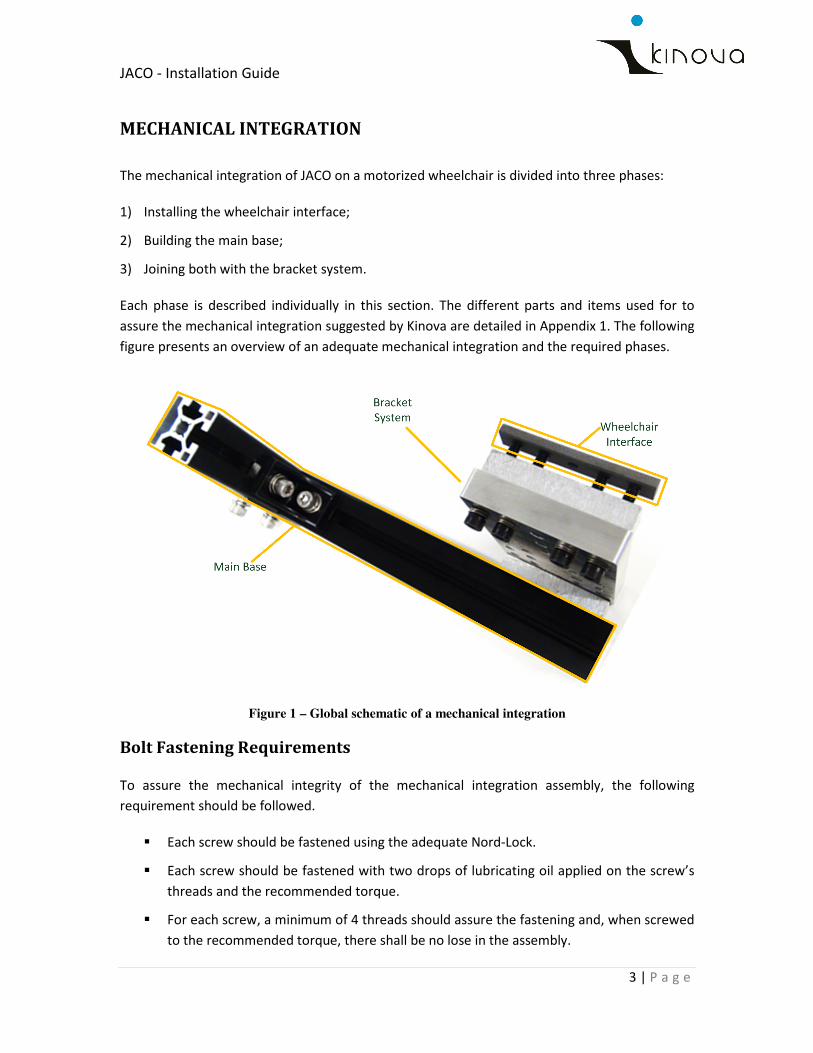
The mechanical integration of JACO on a motorized wheelchair is divided into three phases:
1) Installing the wheelchair interface;
2) Building the main base;
3) Joining both with the bracket system.
Each phase is described individually in this section. The different parts and items used for to
assure the mechanical integration suggested by Kinova are detailed in Appendix 1. The following
figure presents an overview of an adequate mechanical integration and the required phases.
Figure 1 – Global schematic of a mechanical integration
Bolt Fastening Requirements
To assure the mechanical integrity of the mechanical integration assembly, the following
requirement should be followed.
� Each screw should be fastened using the adequate Nord-Lock.
� Each screw should be fastened with two drops of lubricating oil applied on the screw’s
threads and the recommended torque.
� For each screw, a minimum of 4 threads should assure the fastening and, when screwed
to the recommended torque, there shall be no lose in the assembly.
JACO - Installation Guide
4 | P a g e
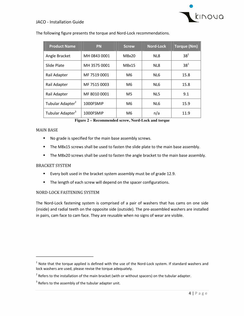
The following figure presents the torque and Nord-Lock recommendations.
Product Name PN Screw Nord-Lock Torque (Nm)
Angle Bracket MH 0843 0001 M8x20 NL8 381
Slide Plate MH 3575 0001 M8x15 NL8 381
Rail Adapter MF 7519 0001 M6 NL6 15.8
Rail Adapter MF 7515 0003 M6 NL6 15.8
Rail Adapter MF 8010 0001 M5 NL5 9.1
Tubular Adapter2 1000FSMIP M6 NL6 15.9
Tubular Adapter3 1000FSMIP M6 n/a 11.9
Figure 2 – Recommended screw, Nord-Lock and torque
MAIN BASE
� No grade is specified for the main base assembly screws.
� The M8x15 screws shall be used to fasten the slide plate to the main base assembly.
� The M8x20 screws shall be used to fasten the angle bracket to the main base assembly.
BRACKET SYSTEM
� Every bolt used in the bracket system assembly must be of grade 12.9.
� The length of each screw will depend on the spacer configurations.
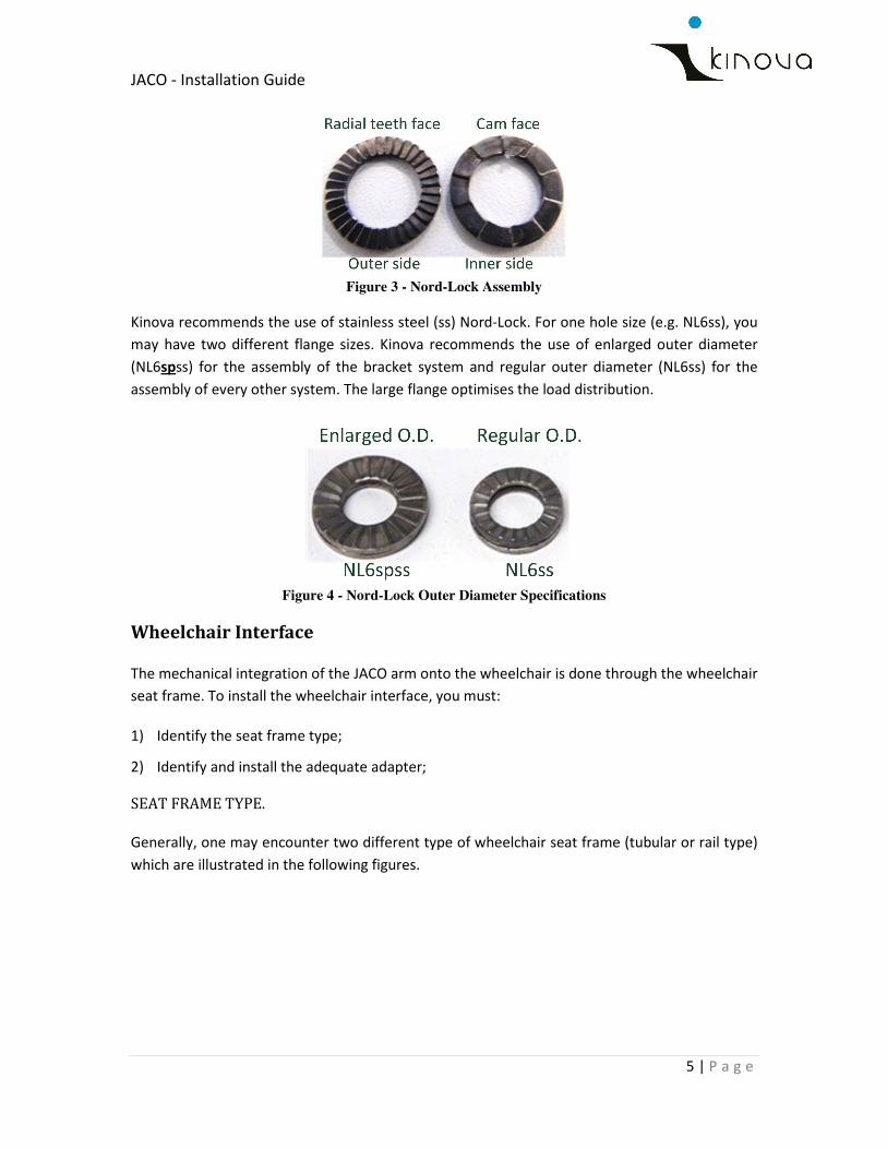
NORD-LOCK FASTENING SYSTEM
The Nord-Lock fastening system is comprised of a pair of washers that has cams on one side
(inside) and radial teeth on the opposite side (outside). The pre-assembled washers are installed
in pairs, cam face to cam face. They are reusable when no signs of wear are visible.
1 Note that the torque applied is defined with the use of the Nord-Lock system. If standard washers and
lock washers are used, please revise the torque adequately.
2 Refers to the installation of the main bracket (with or without spacers) on the tubular adapter.
3 Refers to the assembly of the tubular adapter unit.
JACO - Installation Guide
5 | P a g e
Figure 3 - Nord-Lock Assembly
Kinova recommends the use of stainless steel (ss) Nord-Lock. For one hole size (e.g. NL6ss), you
may have two different flange sizes. Kinova recommends the use of enlarged outer diameter
(NL6spss) for the assembly of the bracket system and regular outer diameter (NL6ss) for the
assembly of every other system. The large flange optimises the load distribution.
Figure 4 - Nord-Lock Outer Diameter Specifications
Wheelchair Interface
The mechanical integration of the JACO arm onto the wheelchair is done through the wheelchair
seat frame. To install the wheelchair interface, you must:
1) Identify the seat frame type;
2) Identify and install the adequate adapter;
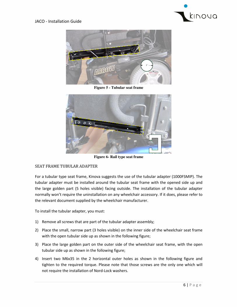
SEAT FRAME TYPE.
Generally, one may encounter two different type of wheelchair seat frame (tubular or rail type)
which are illustrated in the following figures.
JACO - Installation Guide
6 | P a g e
Figure 5 - Tubular seat frame
Figure 6- Rail type seat frame
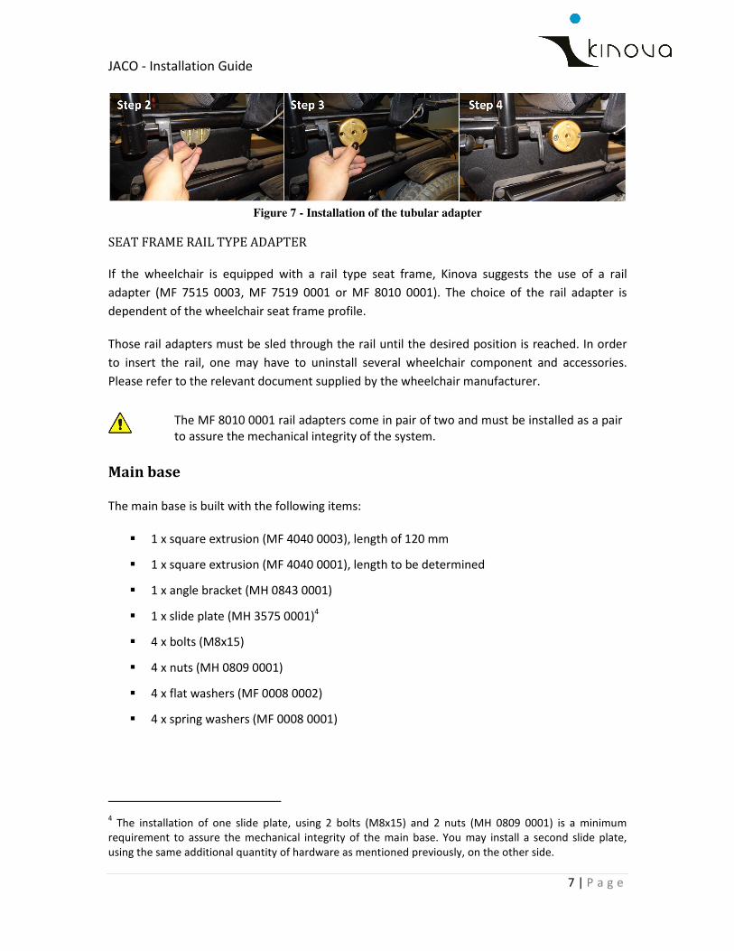
SEAT FRAME TUBULAR ADAPTER
For a tubular type seat frame, Kinova suggests the use of the tubular adapter (1000FSMIP). The
tubular adapter must be installed around the tubular seat frame with the opened side up and
the large golden part (5 holes visible) facing outside. The installation of the tubular adapter
normally won’t require the uninstallation on any wheelchair accessory. If it does, please refer to
the relevant document supplied by the wheelchair manufacturer.
To install the tubular adapter, you must:
1) Remove all screws that are part of the tubular adapter assembly;
2) Place the small, narrow part (3 holes visible) on the inner side of the wheelchair seat frame
with the open tubular side up as shown in the following figure;
3) Place the large golden part on the outer side of the wheelchair seat frame, with the open
tubular side up as shown in the following figure;
4) Insert two M6x35 in the 2 horizontal outer holes as shown in the following figure and
tighten to the required torque. Please note that those screws are the only one which will
not require the installation of Nord-Lock washers.
JACO - Installation Guide
7 | P a g e
Figure 7 - Installation of the tubular adapter
SEAT FRAME RAIL TYPE ADAPTER
If the wheelchair is equipped with a rail type seat frame, Kinova suggests the use of a rail
adapter (MF 7515 0003, MF 7519 0001 or MF 8010 0001). The choice of the rail adapter is
dependent of the wheelchair seat frame profile.
Those rail adapters must be sled through the rail until the desired position is reached. In order
to insert the rail, one may have to uninstall several wheelchair component and accessories.
Please refer to the relevant document supplied by the wheelchair manufacturer.
The MF 8010 0001 rail adapters come in pair of two and must be installed as a pair
to assure the mechanical integrity of the system.
Main base
The main base is built with the following items:
� 1 x square extrusion (MF 4040 0003), length of 120 mm
� 1 x square extrusion (MF 4040 0001), length to be determined
� 1 x angle bracket (MH 0843 0001)
� 1 x slide plate (MH 3575 0001)4
� 4 x bolts (M8x15)
� 4 x nuts (MH 0809 0001)
� 4 x flat washers (MF 0008 0002)
� 4 x spring washers (MF 0008 0001)
4 The installation of one slide plate, using 2 bolts (M8x15) and 2 nuts (MH 0809 0001) is a minimum
requirement to assure the mechanical integrity of the main base. You may install a second slide plate,
using the same additional quantity of hardware as mentioned previously, on the other side.
JACO - Installation Guide
8 | P a g e
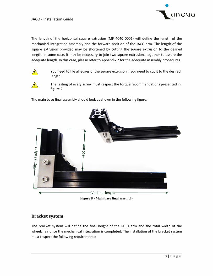
The length of the horizontal square extrusion (MF 4040 0001) will define the length of the
mechanical integration assembly and the forward position of the JACO arm. The length of the
square extrusion provided may be shortened by cutting the square extrusion to the desired
length. In some case, it may be necessary to join two square extrusions together to assure the
adequate length. In this case, please refer to Appendix 2 for the adequate assembly procedures.
You need to file all edges of the square extrusion if you need to cut it to the desired
length.
The fasting of every screw must respect the torque recommendations presented in
figure 2.
The main base final assembly should look as shown in the following figure:
Figure 8 - Main base final assembly
Bracket system
The bracket system will define the final height of the JACO arm and the total width of the
wheelchair once the mechanical integration is completed. The installation of the bracket system
must respect the following requirements:
JACO - Installation Guide
9 | P a g e
� The JACO hand may easily reach the ground, on a surface of about one squared foot, in
an area where the user may have a good visual appreciation of the actions done with
the JACO hand;
� The JACO arm may achieve most of the basic movements without interfering with the
user, the wheelchair or its accessories;
� The JACO arm and its mechanical integration assembly don’t expand the wheelchair
width beyond 2 to 3 inches;
� There is no loose in the mechanical integration assembly.
The fasting of every screw must respect the torque recommendations presented in
figure 2.
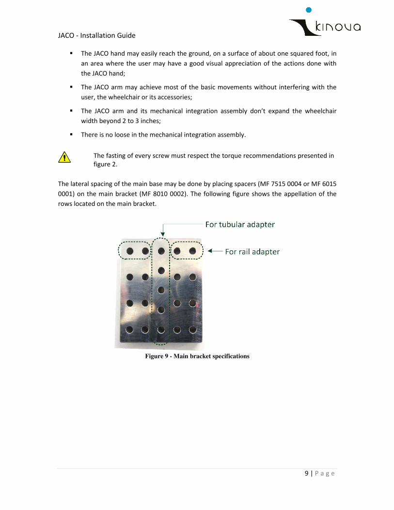
The lateral spacing of the main base may be done by placing spacers (MF 7515 0004 or MF 6015
0001) on the main bracket (MF 8010 0002). The following figure shows the appellation of the
rows located on the main bracket.
Figure 9 - Main bracket specifications
JACO - Installation Guide
10 | P a g e
Please note that:
� Upper spacing refers to spacers used between the main bracket and the rail adapter
(wheelchair).
� Lower spacing refers to spacers used between the main base and the main bracket.
� The square spacers (MF 7515 0004) are used for lower spacing of the main base and the
upper spacing when used with rail adapters (MF 7519 0001, MF 7515 0003 or MF 8010
0001).
� The round spacers (MF 6015 0001) are only used for upper spacing of the main base
when used with tubular adapter (1000FSMIP).
� The quantity of lower and upper spacer will vary depending on the required
configuration.
� Screw lengths shall adjust with the spacing requirements of the bracket system
assembly.
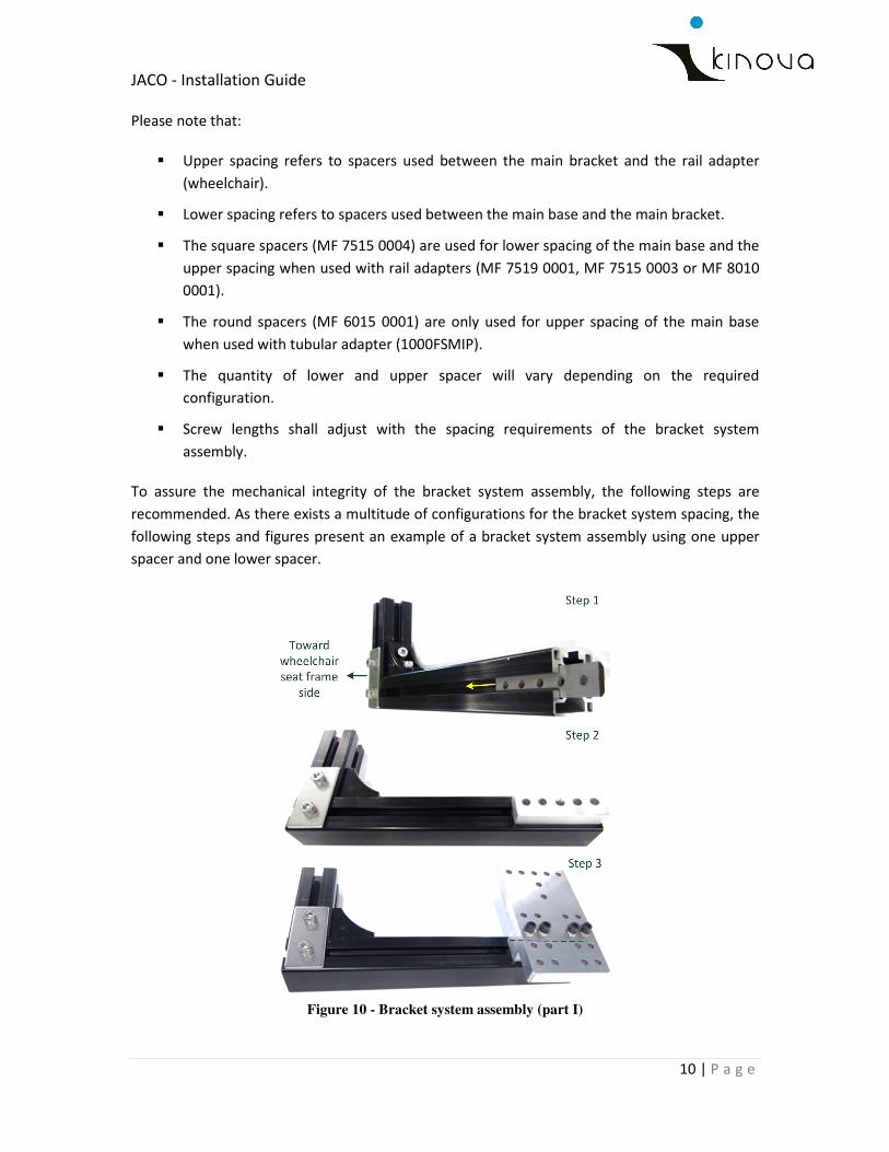
To assure the mechanical integrity of the bracket system assembly, the following steps are
recommended. As there exists a multitude of configurations for the bracket system spacing, the
following steps and figures present an example of a bracket system assembly using one upper
spacer and one lower spacer.
Figure 10 - Bracket system assembly (part I)
JACO - Installation Guide
11 | P a g e
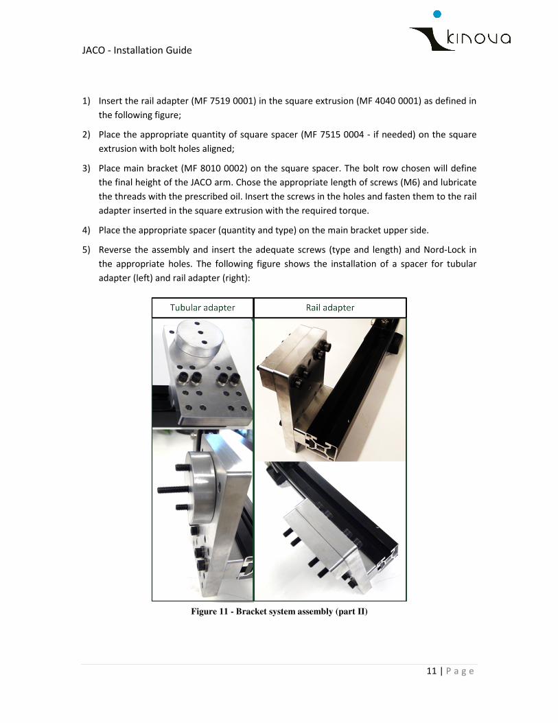
1) Insert the rail adapter (MF 7519 0001) in the square extrusion (MF 4040 0001) as defined in
the following figure;
2) Place the appropriate quantity of square spacer (MF 7515 0004 - if needed) on the square
extrusion with bolt holes aligned;
3) Place main bracket (MF 8010 0002) on the square spacer. The bolt row chosen will define
the final height of the JACO arm. Chose the appropriate length of screws (M6) and lubricate
the threads with the prescribed oil. Insert the screws in the holes and fasten them to the rail
adapter inserted in the square extrusion with the required torque.
4) Place the appropriate spacer (quantity and type) on the main bracket upper side.
5) Reverse the assembly and insert the adequate screws (type and length) and Nord-Lock in
the appropriate holes. The following figure shows the installation of a spacer for tubular
adapter (left) and rail adapter (right):
Figure 11 - Bracket system assembly (part II)

JACO - Installation Guide
12 | P a g e
6) Fasten the bracket system assembly to the adapter (already installed on the wheelchair seat
frame) with the required torque.
Please note that the bracket system requires screws of two different lengths to allow adequate
fastening to the tubular adapter. The middle screw should be about 15 to 20 mm longer than
both extremities screws, as shown in the preceding figure.
Mechanical Integration Assembly Validation
The following validation should be made to the mechanical integration assembly before
installing the JACO arm:
� Verify there is no lose in the mechanical integration assembly by shaking it in all
direction. If a loose is noticed, please verify the torque applied to all screws and screw
length.
You may now install the JACO arm on the main base.
� Verify the JACO arm may be easily installed and uninstalled by a caregiver.
� Assure that there is a sufficient clearance between the JACO fixe base and any part of
the wheelchair to allow easy access to every connectors, buttons and screws located on
the JACO fixed base.
� Once the JACO arm is installed, you should verify the hand may touch the ground on an
appropriate surface and in an appropriate area for easy object pick up by the user.
Before finalizing the installation, the following points should be checked with the user to assure
that the mechanical integration respects his/her daily activities:
� The user may enter his/her adapted transport, secure the wheelchair in place and close
all doors without interfering with JACO;
� The user may slide his/her wheelchair under the tables (only applicable if the user still
needs to slide the wheelchair under the tables);
� The user may move the wheelchair around his/her home and pass through every
doorway.
� The retracted position does not interfere with either the wheelchair or the bracket
system.
� The configuration respects the installation system and the user may close together only
2 fingers.

JACO - Installation Guide
13 | P a g e
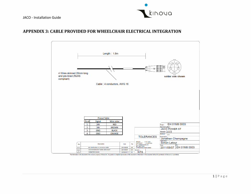
ELECTRICAL INTEGRATION
The power supply to the arm must be 24V D.C. The electrical power provided to the JACO arm,
when used on a motorized wheelchair, will come from both wheelchair batteries. The JACO arm
power cable provided by Kinova is presented in Appendix 3. At one end, it is equipped with the
necessary connector for the JACO base and the other end is equipped with no connector. The 4
free wires at this end are devoted to be joined to the adequate connector to acquire the 24V
D.C. necessary for powering the JACO arm.
It is the responsibility of the technician to assure that the 24V electric outlet is safe for both
JACO and the wheelchair.
Once the cable is adequately prepared, and to assure an adequate electrical integration, please
proceed with the following steps:
1) Find the adequate 24V D.C. outlet on the wheelchair;
2) From the 24V D.C. outlet on the wheelchair to the JACO arm fixe base, define the path that
the power cable will follow;
3) Rout the power cable in a way that it will not interfere with normal wheelchair or swinger
movements and so it is not visually intrusive;
4) Secure the power cable in place.
Assure that the connector is securely connected and will not come out with
wheelchair vibrations.
JACO - Installation Guide
14 | P a g e
CONTROL INTEGRATION
There are two principal ways of achieving the control over JACO when it is installed on a
motorized wheelchair. You may control JACO with
� The Kinova standard joystick;
� The wheelchair control system.
Both methods necessitate special recommendation that will be explained in the following
sections. Note that the control may be customized. Please refer to the Jacosoft User Guide for
detailed information on the configuration methods.
Kinova standard joystick
In order to allow the user to achieve a suitable control over the JACO arm with the Kinova
standard joystick, you must:
1) Define an adequate location5 for the Kinova standard joystick.
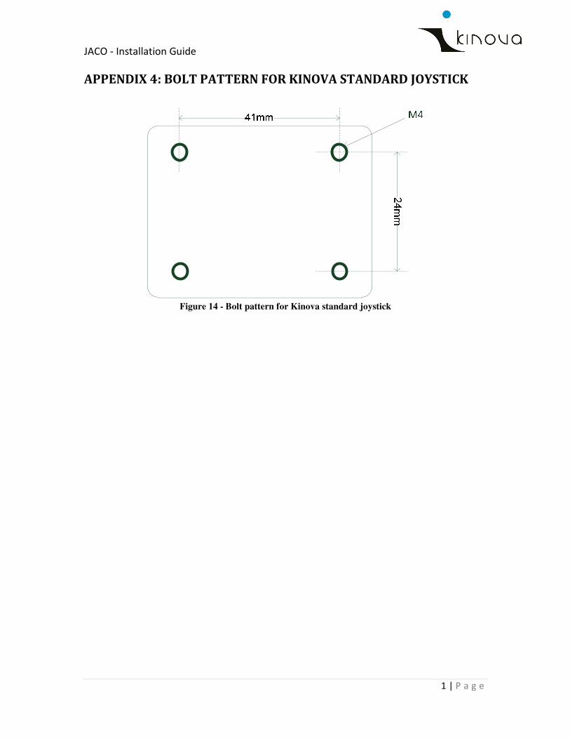
2) Install the Kinova standard joystick and secure it in place. You will find a detailed bolt
pattern for the joystick in Appendix 4 to help you design a joystick support.
3) Rout the joystick cable in a way that it will not interfere with normal wheelchair or swinger
movements and so it is not visually intrusive;
4) Secure the joystick cable in place.
Depending on the user’s physical capacities, additional push buttons may need to be connected
to the joystick. In this case, the emplacement of those push buttons must be studied carefully
and advices of a therapist are recommended.
For more information on the Kinova standard joystick and its functionalities, please refer to the
JACO User Guide.
5 An adequate location refers to a place that won’t interfere with normal user movements, or his control
over the wheelchair. Refer to a therapist for help and approval of the joystick location.
JACO - Installation Guide
15 | P a g e
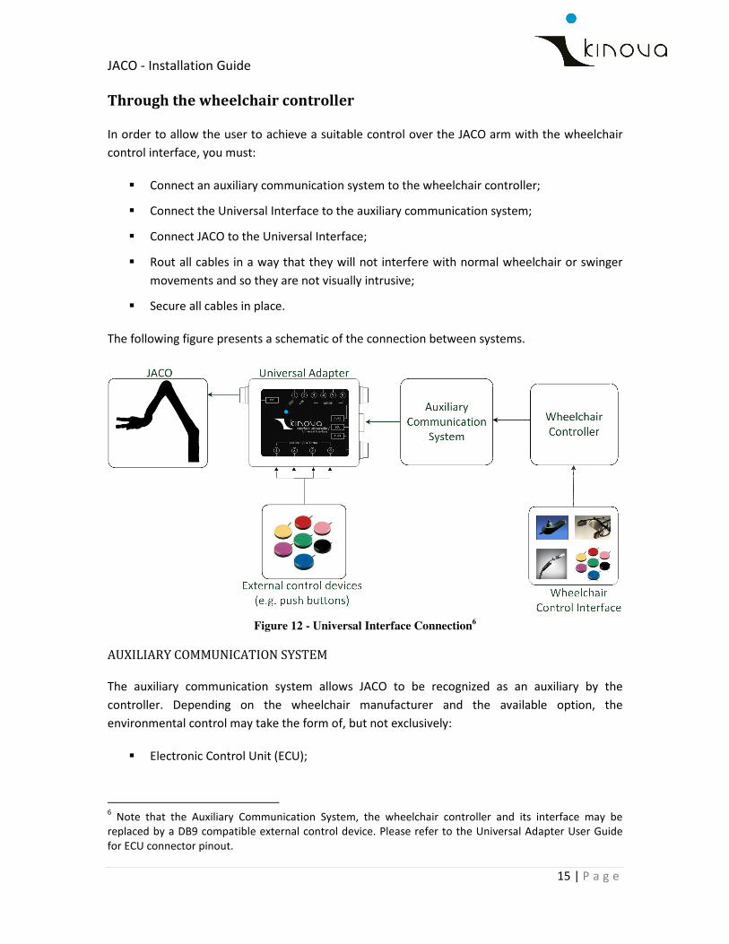
Through the wheelchair controller
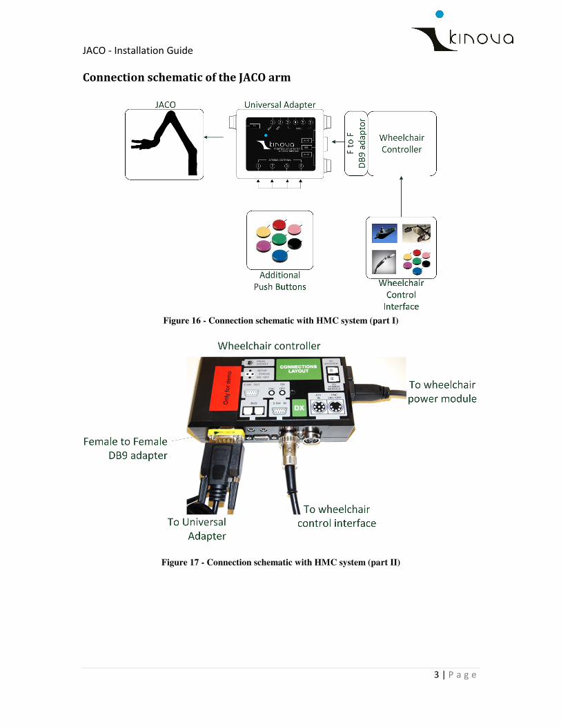
In order to allow the user to achieve a suitable control over the JACO arm with the wheelchair
control interface, you must:
� Connect an auxiliary communication system to the wheelchair controller;
� Connect the Universal Interface to the auxiliary communication system;
� Connect JACO to the Universal Interface;
� Rout all cables in a way that they will not interfere with normal wheelchair or swinger
movements and so they are not visually intrusive;
� Secure all cables in place.
The following figure presents a schematic of the connection between systems.
Figure 12 - Universal Interface Connection
6
AUXILIARY COMMUNICATION SYSTEM
The auxiliary communication system allows JACO to be recognized as an auxiliary by the
controller. Depending on the wheelchair manufacturer and the available option, the
environmental control may take the form of, but not exclusively:
� Electronic Control Unit (ECU);
6 Note that the Auxiliary Communication System, the wheelchair controller and its interface may be
replaced by a DB9 compatible external control device. Please refer to the Universal Adapter User Guide
for ECU connector pinout.

JACO - Installation Guide
16 | P a g e
� Input/Output Module (IOM)7;
� Mouse Emulator;
� Bluetooth module.
This auxiliary communication system will transfer the controller output to the Universal
Interface. The auxiliary communication system must be connected to the controller. Please refer
to the documents provided by the wheelchair manufacturer for detailed procedure.
UNIVERSAL INTERFACE
The Universal Interface is an electronic device which translates the output of the auxiliary
communication system into an adequate command to JACO.
Additional push buttons must be connected to the Universal Interface to allow reaching Home
and Retract positions and toggling between modes of operation. In this case, the emplacement
of those push buttons must be studied carefully and advices of a therapist are recommended.
7 See Appendix 5 for detailed information on how to connect the JACO arm to an HMC system.

JACO - Installation Guide
17 | P a g e
CONTACT SUPPORT
If you need help, have questions or comments about this guide or the information detailed in it,
please contact Kinova at: [email protected]
www.kinovaRobotics.com
JACO - Installation Guide
18 | P a g e
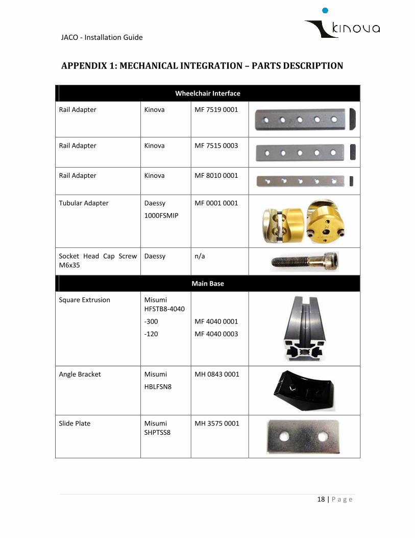
APPENDIX 1: MECHANICAL INTEGRATION – PARTS DESCRIPTION
Wheelchair Interface
Rail Adapter Kinova MF 7519 0001
Rail Adapter Kinova MF 7515 0003
Rail Adapter Kinova MF 8010 0001
Tubular Adapter Daessy
1000FSMIP
MF 0001 0001
Socket Head Cap Screw
M6x35
Daessy n/a
Main Base
Square Extrusion Misumi
HFSTB8-4040
-300
-120
Misumi HFSTB8-
4040
MF 4040 0001
MF 4040 0003
Angle Bracket Misumi
HBLFSN8
MH 0843 0001
Slide Plate Misumi
SHPTSS8
MH 3575 0001
JACO - Installation Guide
19 | P a g e
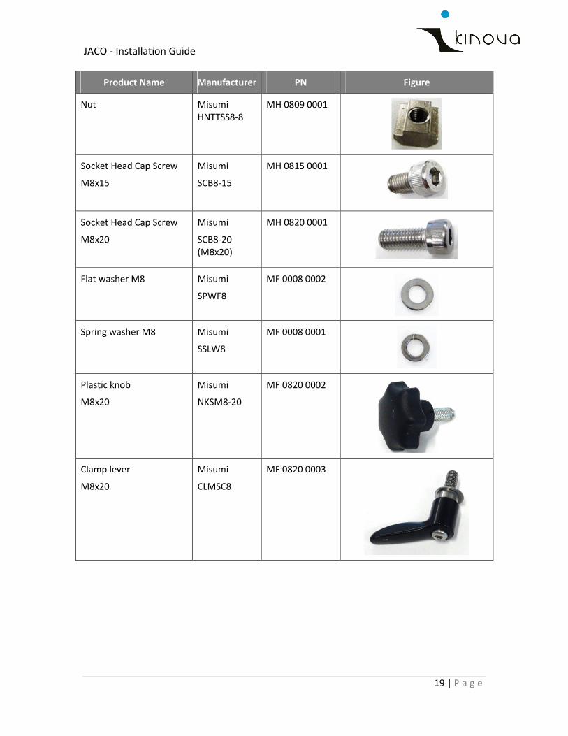
Product Name Manufacturer PN Figure
Nut Misumi
HNTTSS8-8
MH 0809 0001
Socket Head Cap Screw
M8x15
Misumi
SCB8-15
MH 0815 0001
Socket Head Cap Screw
M8x20
Misumi
SCB8-20
(M8x20)
MH 0820 0001
Flat washer M8 Misumi
SPWF8
MF 0008 0002
Spring washer M8 Misumi
SSLW8
MF 0008 0001
Plastic knob
M8x20
Misumi
NKSM8-20
MF 0820 0002
Clamp lever
M8x20
Misumi
CLMSC8
MF 0820 0003
JACO - Installation Guide
20 | P a g e
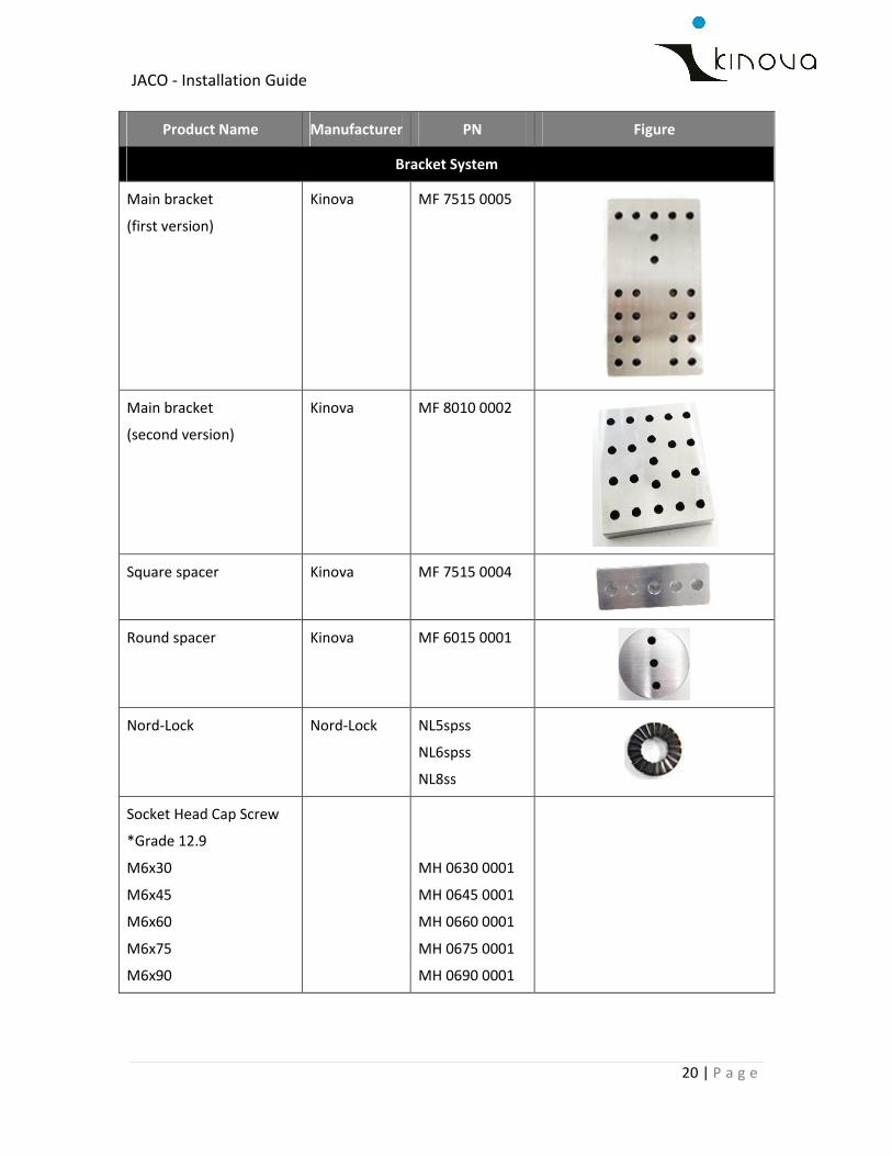
Product Name Manufacturer PN Figure
Bracket System
Main bracket
(first version)
Kinova MF 7515 0005
Main bracket
(second version)
Kinova MF 8010 0002
Square spacer Kinova MF 7515 0004
Round spacer Kinova MF 6015 0001
Nord-Lock Nord-Lock NL5spss
NL6spss
NL8ss
Socket Head Cap Screw
*Grade 12.9
M6x30
M6x45
M6x60
M6x75
M6x90
MH 0630 0001
MH 0645 0001
MH 0660 0001
MH 0675 0001
MH 0690 0001
JACO - Installation Guide
21 | P a g e
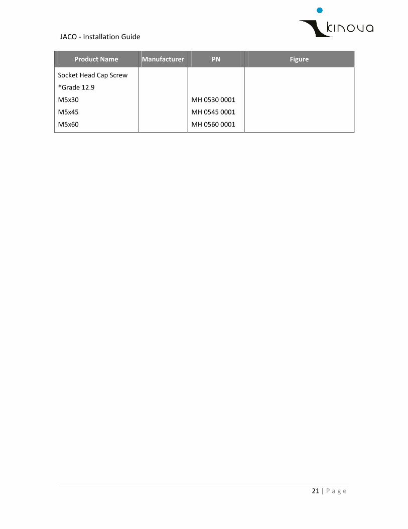
Product Name Manufacturer PN Figure
Socket Head Cap Screw
*Grade 12.9
M5x30
M5x45
M5x60
MH 0530 0001
MH 0545 0001
MH 0560 0001
JACO - Installation Guide
22 | P a g e
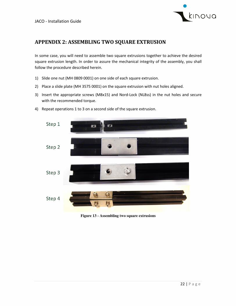
APPENDIX 2: ASSEMBLING TWO SQUARE EXTRUSION
In some case, you will need to assemble two square extrusions together to achieve the desired
square extrusion length. In order to assure the mechanical integrity of the assembly, you shall
follow the procedure described herein.
1) Slide one nut (MH 0809 0001) on one side of each square extrusion.
2) Place a slide plate (MH 3575 0001) on the square extrusion with nut holes aligned.
3) Insert the appropriate screws (M8x15) and Nord-Lock (NL8ss) in the nut holes and secure
with the recommended torque.
4) Repeat operations 1 to 3 on a second side of the square extrusion.
Figure 13 - Assembling two square extrusions
JACO - Installation Guide
1 | P a g e
APPENDIX 3: CABLE PROVIDED FOR WHEELCHAIR ELECTRICAL INTEGRATION
JACO - Installation Guide
1 | P a g e
APPENDIX 4: BOLT PATTERN FOR KINOVA STANDARD JOYSTICK
Figure 14 - Bolt pattern for Kinova standard joystick
JACO - Installation Guide
2 | P a g e
APPENDIX 5: CONTROL INTERFACE FOR HMC
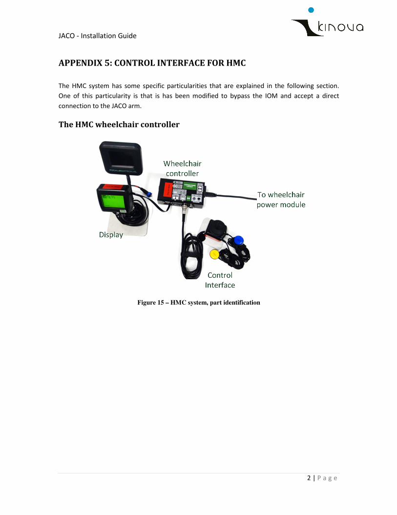
The HMC system has some specific particularities that are explained in the following section.
One of this particularity is that is has been modified to bypass the IOM and accept a direct
connection to the JACO arm.
The HMC wheelchair controller
Figure 15 – HMC system, part identification
JACO - Installation Guide
3 | P a g e
Connection schematic of the JACO arm
Figure 16 - Connection schematic with HMC system (part I)
Figure 17 - Connection schematic with HMC system (part II)
JACO - Installation Guide
4 | P a g e
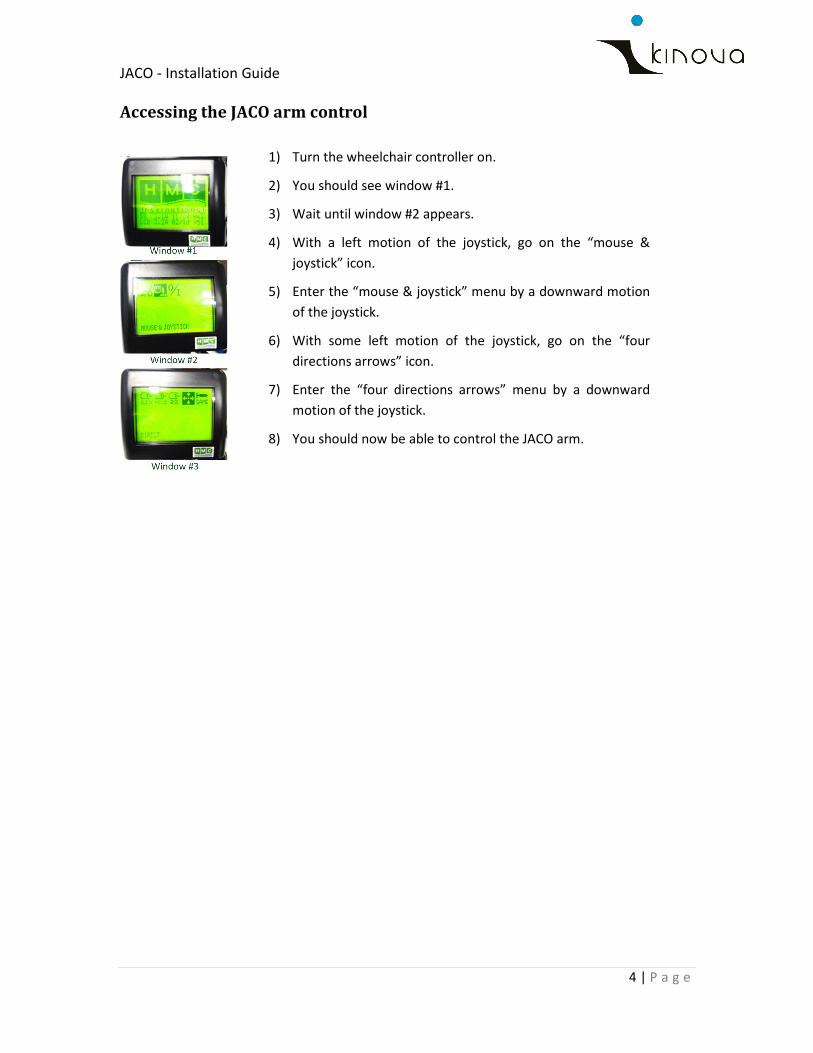
Accessing the JACO arm control
1) Turn the wheelchair controller on.
2) You should see window #1.
3) Wait until window #2 appears.
4) With a left motion of the joystick, go on the “mouse &
joystick” icon.
5) Enter the “mouse & joystick” menu by a downward motion
of the joystick.
6) With some left motion of the joystick, go on the “four
directions arrows” icon.
7) Enter the “four directions arrows” menu by a downward
motion of the joystick.
8) You should now be able to control the JACO arm.