Embed Size (px)
Citation preview

I n t e r n a t i o n a l T e l e c o m m u n i c a t i o n U n i o n
ITU-T L.206 TELECOMMUNICATION STANDARDIZATION SECTOR OF ITU
(08/2017)
SERIES L: ENVIRONMENT AND ICTS, CLIMATE CHANGE, E-WASTE, ENERGY EFFICIENCY; CONSTRUCTION, INSTALLATION AND PROTECTION OF CABLES AND OTHER ELEMENTS OF OUTSIDE PLANT
Optical infrastructures – Infrastructure including node elements (except cables)
Requirements for passive optical nodes – Outdoor optical cross-connect cabinets
Recommendation ITU-T L.206
ITU-T L-SERIES RECOMMENDATIONS
ENVIRONMENT AND ICTS, CLIMATE CHANGE, E-WASTE, ENERGY EFFICIENCY; CONSTRUCTION,
INSTALLATION AND PROTECTION OF CABLES AND OTHER ELEMENTS OF OUTSIDE PLANT
OPTICAL FIBRE CABLES
Cable structure and characteristics L.100–L.124
Cable evaluation L.125–L.149
Guidance and installation technique L.150–L.199
OPTICAL INFRASTRUCTURES
Infrastructure including node elements (except cables) L.200–L.249
General aspects and network design L.250–L.299
MAINTENANCE AND OPERATION
Optical fibre cable maintenance L.300–L.329
Infrastructure maintenance L.330–L.349
Operation support and infrastructure management L.350–L.379
Disaster management L.380–L.399
PASSIVE OPTICAL DEVICES L.400–L.429
MARINIZED TERRESTRIAL CABLES L.430–L.449
For further details, please refer to the list of ITU-T Recommendations.
Rec. ITU-T L.206 (08/2017) i
Recommendation ITU-T L.206
Requirements for passive optical nodes –
Outdoor optical cross-connect cabinets
Summary
Recommendation ITU-T L.206 refers to outdoor optical cross-connect cabinets deployed as passive
optical nodes in outdoor environments. It deals with the cabinet housing, internal fibre management
system, cable attachment and termination system, and also specifies the mechanical and environmental
characteristics.
History
Edition Recommendation Approval Study Group Unique ID*
1.0 ITU-T L.206 2017-08-13 15 11.1002/1000/13296
Keywords
Enclosures, interconnection, optical cross-connect cabinets, outside plant, passive optical nodes.
* To access the Recommendation, type the URL http://handle.itu.int/ in the address field of your web
browser, followed by the Recommendation's unique ID. For example, http://handle.itu.int/11.1002/1000/11
830-en.
ii Rec. ITU-T L.206 (08/2017)
FOREWORD
The International Telecommunication Union (ITU) is the United Nations specialized agency in the field of
telecommunications, information and communication technologies (ICTs). The ITU Telecommunication
Standardization Sector (ITU-T) is a permanent organ of ITU. ITU-T is responsible for studying technical,
operating and tariff questions and issuing Recommendations on them with a view to standardizing
telecommunications on a worldwide basis.
The World Telecommunication Standardization Assembly (WTSA), which meets every four years, establishes
the topics for study by the ITU-T study groups which, in turn, produce Recommendations on these topics.
The approval of ITU-T Recommendations is covered by the procedure laid down in WTSA Resolution 1.
In some areas of information technology which fall within ITU-T's purview, the necessary standards are
prepared on a collaborative basis with ISO and IEC.
NOTE
In this Recommendation, the expression "Administration" is used for conciseness to indicate both a
telecommunication administration and a recognized operating agency.
Compliance with this Recommendation is voluntary. However, the Recommendation may contain certain
mandatory provisions (to ensure, e.g., interoperability or applicability) and compliance with the
Recommendation is achieved when all of these mandatory provisions are met. The words "shall" or some other
obligatory language such as "must" and the negative equivalents are used to express requirements. The use of
such words does not suggest that compliance with the Recommendation is required of any party.
INTELLECTUAL PROPERTY RIGHTS
ITU draws attention to the possibility that the practice or implementation of this Recommendation may involve
the use of a claimed Intellectual Property Right. ITU takes no position concerning the evidence, validity or
applicability of claimed Intellectual Property Rights, whether asserted by ITU members or others outside of
the Recommendation development process.
As of the date of approval of this Recommendation, ITU had not received notice of intellectual property,
protected by patents, which may be required to implement this Recommendation. However, implementers are
cautioned that this may not represent the latest information and are therefore strongly urged to consult the TSB
patent database at http://www.itu.int/ITU-T/ipr/.
ITU 2017
All rights reserved. No part of this publication may be reproduced, by any means whatsoever, without the prior
written permission of ITU.
Rec. ITU-T L.206 (08/2017) iii
Table of Contents
Page
1 Scope ............................................................................................................................. 1
2 References ..................................................................................................................... 1
3 Definitions .................................................................................................................... 2
3.1 Terms defined elsewhere ................................................................................ 2
3.2 Terms defined in this Recommendation ......................................................... 2
4 Abbreviations and acronyms ........................................................................................ 3
5 Conventions .................................................................................................................. 3
6 Characteristics of optical cross-connect cabinets ......................................................... 3
6.1 General requirements ...................................................................................... 3
6.2 Cabinet housing .............................................................................................. 4
6.3 Fibre management system (organizer system) ............................................... 5
6.4 Cable attachment and termination system ...................................................... 8
7 Performance evaluation test programme ...................................................................... 9
8 Sample preparation ....................................................................................................... 9
Annex A – Performance evaluation criteria ............................................................................. 11
A.1 Mechanical and sealing evaluation ................................................................. 11
A.2 Optical evaluation ........................................................................................... 11
Annex B – Performance test programme for ground level and above ground cabinets ......... 13
B.1 Mechanical and sealing evaluation ................................................................. 13
B.2 Optical evaluation ........................................................................................... 15
Appendix I – Sample illustrations of cabinet structure ............................................................ 17
Appendix II – Product characterization checklist .................................................................... 21
Bibliography............................................................................................................................. 24
iv Rec. ITU-T L.206 (08/2017)
Introduction
Cabinets are widely used for protection of cross-connection points among multiple cables in outdoor
environments. A cabinet along with internal functional assemblies can be referred to as an outdoor
cross-connect cabinet.
An optical cross-connect cabinet comprises a mechanical structure (cabinet housing) for mechanical
protection and environmental sealing of internal systems, a fibre management system for guiding and
managing the fibres and fibre connections inside the node, and a cable attachment and termination
system for attaching and terminating the cable ends. Patch cords, splitters and other passive optical
devices are optional accessories of a cabinet. The optical cross-connect cabinet will:
– work as a cross-connection area in outdoor plant;
– protect the fibres, fibre joints and optical devices from the outdoor environment at ground
level (normally, on a concrete base) and above ground (e.g., wall mounted or pole mounted
by steel supports);
– provide for the organization of the fibre joints, passive devices and the storage of fibre
overlength (excess fibre length);
– provide electrical bonding and grounding of the metal parts of the cable sheath and strength
members.
This Recommendation specifies the requirements of optical cross-connect cabinets and the means for
characterization and evaluation of the performance of cabinets according to the principles of
[ITU-T L.200]. This includes mechanical performance, sealing performance and optical stability of
the product which simulate the effect of environmental factors or interventions related to network
maintenance and reconfiguration. It contains a basic test programme for the cabinet that is globally
applicable. Additional requirements may be agreed between customer and supplier to reflect local or
special conditions. All functions and features that a product may contain should be reflected in the
mix of test samples that are subjected to the test programme.
Rec. ITU-T L.206 (08/2017) 1
Recommendation ITU-T L.206
Requirements for passive optical nodes –
Outdoor optical cross-connect cabinets
1 Scope
This Recommendation:
– refers to optical cross-connect cabinets as passive optical nodes in outdoor environments;
– deals with the cabinet housing as well as the fibre management system, and the cable
attachment and termination system;
– specifies mechanical and environmental characteristics of the optical cabinets;
– specifies characteristics of the fibre management system;
– provides a test plan for the performance evaluation of outdoor optical cross-connect cabinets;
– supplies the simulation of the effect of interventions related to network maintenance and
reconfiguration;
– gives a checklist for a systematic product characterization according to [ITU-T L.200].
2 References
The following ITU-T Recommendations and other references contain provisions which, through
reference in this text, constitute provisions of this Recommendation. At the time of publication, the
editions indicated were valid. All Recommendations and other references are subject to revision;
users of this Recommendation are therefore encouraged to investigate the possibility of applying the
most recent edition of the Recommendations and other references listed below. A list of the currently
valid ITU-T Recommendations is regularly published. The reference to a document within this
Recommendation does not give it, as a stand-alone document, the status of a Recommendation.
[ITU-T G.652] Recommendation ITU-T G.652 (2016), Characteristics of a single-mode
optical fibre and cable.
[ITU-T G.657] Recommendation ITU-T G.657 (2016), Characteristics of a bending-loss
insensitive single-mode optical fibre and cable.
[ITU-T K.11] Recommendation ITU-T K.11 (2009), Principles of protection against
overvoltages and overcurrents.
[ITU-T K.47] Recommendation ITU-T K.47 (2012), Protection of telecommunication
lines against direct lightning flashes.
[ITU-T L.200] Recommendation ITU-T L.200/L.51 (2003), Passive node elements for fibre
optic networks – General principles and definitions for characterization and
performance evaluation.
[ITU-T L.361] Recommendation ITU-T L.361/L.64 (2012), ID tag requirements for
infrastructure and network elements management.
[IEC 60529] IEC 60529:2013, Degrees of protection provided by enclosures (IP Code).
[IEC 61300-2-1] IEC 61300-2-1:2009, Fibre optic interconnecting devices and passive
components – Basic test and measurement procedures – Part 2-1: Tests –
Vibration (sinusoidal).
2 Rec. ITU-T L.206 (08/2017)
[IEC 61300-2-4] IEC 61300-2-4:1995, Fibre optic interconnecting devices and passive
components – Basic test and measurement procedures – Part 2-4: Tests –
Fibre/cable retention.
[IEC 61300-2-5] IEC 61300-2-5:2009, Fibre optic interconnecting devices and passive
components – Basic test and measurement procedures – Part 2-5: Tests –
Torsion.
[IEC 61300-2-9] IEC 61300-2-9:2017, Fibre optic interconnecting devices and passive
components – Basic test and measurement procedures – Part 2-9: Tests –
Shock.
[IEC 61300-2-12] IEC 61300-2-12:2009, Fibre optic interconnecting devices and passive
components – Basic test and measurement procedures – Part 2-12: Tests –
Impact.
[IEC 61300-2-22] IEC 61300-2-22:2007, Fibre optic interconnecting devices and passive
components – Basic test and measurement procedures – Part 2-22: Tests –
Change of temperature.
[IEC 61300-2-26] IEC 61300-2-26:2006, Fibre optic interconnecting devices and passive
components – Basic test and measurement procedures – Part 2-26: Tests –
Salt mist.
[IEC 61300-2-33] IEC 61300-2-33:2012, Fibre optic interconnecting devices and passive
components - Basic test and measurement procedures – Part 2-33: Tests –
Assembly and disassembly of fibre optic mechanical splices, fibre
management systems and closures.
[IEC 61300-2-34] IEC 61300-2-34:2009, Fibre optic interconnecting devices and passive
components – Basic test and measurement procedures – Part 2-34: Tests –
Resistance to solvents and contaminating fluids of interconnecting
components and closures.
[IEC 61300-2-37] IEC 61300-2-37:2016, Fibre optic interconnecting devices and passive
components – Basic test and measurement procedures – Part 2-37: Tests –
Cable bending for fibre optic closures.
[IEC 61300-3-1] IEC 61300-3-1 (2005), Fibre optic interconnecting devices and passive
components – Basic test and measurement procedures – Part 3-1:
Examinations and measurements – Visual examination.
[IEC 61300-3-3] IEC 61300-3-3:2009, Fibre optic interconnecting devices and passive
components – Basic test and measurement procedures – Part 3-3:
Examinations and measurements – Active monitoring of changes in
attenuation and return loss.
[IEC 61300-3-28] IEC 61300-3-28:2012, Fibre optic interconnecting devices and passive
components – Basic test and measurement procedures – Part 3-28:
Examinations and measurements – Transient loss.
3 Definitions
3.1 Terms defined elsewhere
None.
3.2 Terms defined in this Recommendation
This Recommendation defines the following terms:
Rec. ITU-T L.206 (08/2017) 3
3.2.1 optical cross-connect cabinet: A cabinet with an integrated fibre management system to
protect the cross-connections of optical fibre cables.
3.2.2 cabinet housing: The outer shell of a cabinet, including lockable doors and not including the
fibre management system or the cable attachment and termination system. Its main functions are
protection and sealing of its contents.
3.2.3 fibre management system (organizer system): The whole of the means and features that
guide and store fibres and passive devices inside a node, at any location where they are not protected
by the cable sheath. In a cabinet, the optical fibres are properly managed and guided from where
cables enter the node until their exit.
4 Abbreviations and acronyms
This Recommendation uses the following abbreviations and acronyms:
ID Identification
IP Ingress Protection
ME Multiple Element (mass storage)
OA Outdoor Above ground
OG Outdoor Ground level
SC Single Circuit
SE Single Element
SF Single Fibre
SMC Sheet Moulding Compound
SR Single Ribbon
5 Conventions
None.
6 Characteristics of optical cross-connect cabinets
6.1 General requirements
The general structure of optical cabinets is shown in Figure 1.

4 Rec. ITU-T L.206 (08/2017)
Figure 1 – General structure of optical cabinets
Each cabinet should comply with the general requirements as listed in clause 8 of [ITU-T L.200].
Figures I.1 to I.4 show examples of cabinets to illustrate their structures and internal fibre organization
systems.
6.2 Cabinet housing
The following should be considered:
– dimensions should be compatible with internal contents and installation site. Generally, the
maximum height of cabinet should be less than 1.6 m;
– the doors should be re-openable for installation, maintenance or reconfiguration. The opening
angle of the door should not be less than 110o and the lock on the door should have sufficient
protection ability;
– the protection level of the cabinet housing should comply with the requirements of IP54 or
higher degrees in [IEC 60529];
– the cabinet housing should be made from high strength materials to provide sufficient
mechanical strength, e.g., metal or sheet moulding compound (SMC; sheet form glass-fibre
reinforced polyester material processed by compression moulding);
– the metallic parts of the cabinet housing should be electrically bonded and grounded;
– the housing should allow access for multiple cable ends. The cables may be of different sizes
or types. Normally, the cables enter the cabinet from the bottom of the housing via cable
entry holes. The apertures between cables and the housing should allow sealing by putty or
other materials to ensure adequate performance, and the sealing material should be easily
removable for reconfiguration;
– the housing should stand and be fixable on a concrete base or steel supports;
– if the housing is limited to use in certain applications and environments in the network, any
limitations should be clearly indicated to the user – a detailed characterization of features and
compatibility of a cabinet can be assessed using the checklist in Appendix II;
– if necessary, a cabinet can be equipped with an access control system that makes remote door
control (via a dedicated network) available;
Rec. ITU-T L.206 (08/2017) 5
– materials that will be exposed to solar radiation should be resistant to ultraviolet light. All
polymeric materials that are exposed to the environment should be sufficiently resistant to
fungi. Metallic parts should be corrosion resistant when exposed to the salt mist test
[IEC 61300-2-26].
6.3 Fibre management system (organizer system)
The fibre management system is an integral part of an optical cross-connect cabinet. The system
comprises units or modules and support frames that have means for routing and holding fibre joints,
fibre overlength, patch cords and other possible passive devices (splitters, adapters, etc.) in an orderly
manner, and should minimize fibre strain.
Compatibility and features of fibre management system can be assessed by using the checklist in
Appendix II. The desired optical stability type can be selected according to [ITU-T L.200].
6.3.1 Functions of the fibre management system
The functions of the optical fibre management system are:
– to provide means for routing, storing and protecting fibre joints or other passive devices in a
predetermined order, from one cable sheath end to another;
– to provide means for installation, reconfiguration and expansion of fibre circuits, to make the
cabinet a flexible optical cross-connection point;
– to separate circuits up to a certain degree as defined in [ITU-T L.200]. This will limit the risk
of interruption of traffic to those fibres that belong to the same group of circuits (see
[ITU-T L.200]: single fibre (SF), single circuit (SC), single ribbon (SR), single element (SE)
or multiple element (ME). For an optical cross-connect cabinet, a separation degree higher
than SE is preferred;
– to provide means for storing the fibre overlength required for jointing and for possible
re-jointing in the future;
– to ensure that the fibre bend radius is not less than 30 mm in general applications with
ITU-T G.652 fibres. For special applications, a minimum bend radius of 20 mm can be agreed
between customer and supplier (in order to maintain mechanical reliability and minimize
losses in the network, the cumulative length of fibre exposed to this smaller bend radius
should be limited to less than 2 m per fibre link). In the case of ITU-T G.657 fibres, smaller
bend radius is allowed (see [b-ITU-T G-Sup.59] for guidance on optical fibre and cable
reliability);
– to provide easy identification and access to any connectors and stored fibre joints for
maintenance and reconfiguration, all optical connectors (including optical adapters and
plugs) should be labelled clearly and uniquely to identify their routes. Electronic
identification (ID) is optional, which should comply with the requirements of [ITU-T L.361].
The materials used for making the management system should be compatible with the other materials
in the cabinet and the degreasing agents as recommended in the installation instructions.
6.3.2 Modules of fibre management system
The fibre management system may contain the following modules:
a) Splice modules
Splice modules, normally in the form of trays, are used for storing and protecting fibre splices
and fibre overlength.
Splice modules can store splices of the fibres from the ingoing and outgoing cables together
(direct splicing modules) or can store splices of the fibres from the ingoing and outgoing
cables to pigtails.
6 Rec. ITU-T L.206 (08/2017)
In some cases, the splice modules can store the splitter components which are then spliced to
the fibres of the cables or pigtails.
b) Distribution modules
Distribution modules, normally in the form of trays, have fibre distribution function that
allows a cross-connection between the ingoing and outgoing fibres by using patch panels.
Typically, patch cords are used in cross-connection between the distributing modules.
c) Storage modules for cable overlength (excess cable length)
Storage modules, normally in the form of winding wheels, are capable of storing cable
overlength of patch cords and pigtails. Normally, storage of fibre overlength is done in the
splice modules.
d) Splitter modules
Splitter modules, normally in the form of trays with splitters inside or individual splitters, are
capable of splitting optical power into different branches of the network. In most cases, the
splitter ports are connectorized to allow fast installation or reconfiguration.
Several functions of different modules can be combined into one module. For example, some modules
have combined the splicing and the distribution function into one ''splice and distribution module''.
Modules in the form of trays may be organized in one of the following ways:
– lateral sliding from a frame – similar to removing a book from a shelf;
– lateral rotation about a vertical axial – similar to turning a blade out of a pen knife;
– hinging – similar to turning pages in a book.
All movements of the trays should proceed in a predetermined and controlled way in order to reduce
optical losses or interruption of traffic during organizer manipulations.
6.3.3 Configurations of optical fibre management system
Various configurations of the fibre management system in the cross-connect cabinet are possible: a)
to h).
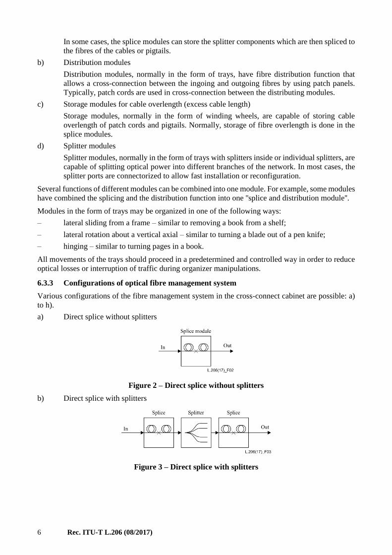
a) Direct splice without splitters
Figure 2 – Direct splice without splitters
b) Direct splice with splitters
Figure 3 – Direct splice with splitters
Rec. ITU-T L.206 (08/2017) 7
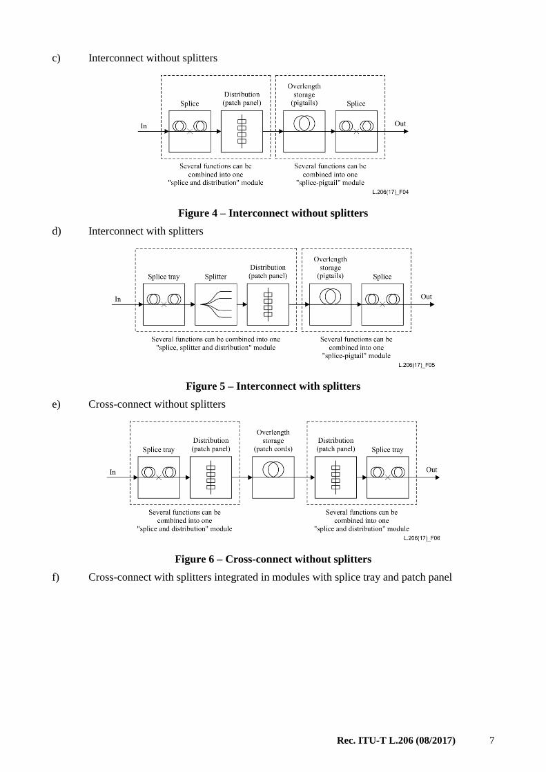
c) Interconnect without splitters
Figure 4 – Interconnect without splitters
d) Interconnect with splitters
Figure 5 – Interconnect with splitters
e) Cross-connect without splitters
Figure 6 – Cross-connect without splitters
f) Cross-connect with splitters integrated in modules with splice tray and patch panel

8 Rec. ITU-T L.206 (08/2017)
Figure 7 – Cross-connect with splitters integrated in modules
with splice tray and patch panel
g) Cross-connect with individual pigtailed splitter modules
Figure 8 – Cross-connect with individual pigtailed splitter modules
h) Cross-connect with individual splitter and distribution modules
Figure 9 – Cross-connect with individual splitter and distribution modules
If required, the fibre management system can be divided into multiple subsystems and stored in
separate regions in the cabinet so that multiple telecommunication operators can share the subscriber
cables and the space inside the cabinet. In this case, the separated regions should be independently
lockable and easy to identify.
6.4 Cable attachment and termination system
The following characteristics of cable attachment and termination system should be considered:
– the system should allow for attachment of all cables entering the cabinet. The cables may be
of different sizes or types;

Rec. ITU-T L.206 (08/2017) 9
– the system should allow for good bonding and grounding for metallic elements of cables,
while the cable metallic elements should be insulated to other metallic parts of the cabinet.
The method of achieving electrical continuity will vary with the type of cable sheath and the
type and location of the strength members. Further information is given in [ITU-T K.11] and
[ITU-T K.47];
– the system should be installed near the cable entry points in the cabinet, normally the lower
section of the cabinet inner housing;
– the system should allow the addition or removal of cables with no interruption to service on
other cables;
– the materials used in the system should be compatible with the other materials in the cabinet
and the degreasing agents recommended in the installation instructions.
7 Performance evaluation test programme
The complete test programme for an optical cross-connect cabinet consists of:
– a basic test programme for the applicable environment (see Annexes A and B);
– a number of additional requirements according to local standards when necessary (see
[ITU-T L.200] and the checklist in Appendix II).
For specific products, alternative test conditions to those given in Annex B may be agreed between
customer and supplier.
Tests should be executed according to IEC 61300-2-series test methods where available.
The performance test programme of an optical cross-connect cabinet should:
– evaluate the product for two groups of criteria: mechanical and sealing evaluation, and optical
stability (see Annex A);
– simulate the effects of exposure to:
• the environment in which it will be installed,
• an intervention at the node;
– simulate installation or maintenance conditions;
– evaluate all available features of the product.
When an optical cross-connect cabinet is suitable for both outdoor above ground (OA) and outdoor
ground level (OG) environments (see [ITU-T L.200]), it should pass the most severe conditions of
either environment. As an alternative, the tests that are different for each of these environments may
be duplicated at both settings.
Two types of optical stability can be selected (see clause 6.2.1 of [ITU-T L.200]). For products that
may be subject to an intervention on a live network, dynamic optical stability is recommended.
8 Sample preparation
A representative number of test samples is to be prepared, taking into account the following
parameters:
– all product features and compatibility (see checklist in Appendix II);
– applicable sizes of cables;
– sealing performance test samples should be installed at −15°C, room temperature or +45°C;
– optical performance test samples should be installed at room temperature;
10 Rec. ITU-T L.206 (08/2017)
– for mechanical evaluation, a fresh sample should be prepared for each different test; if a
failure occurs when consecutive testing is applied on the same sample, the failed test may be
repeated on a fresh sample.
Appendix I of [ITU-T L.200] illustrates how optical samples can be prepared. Due to their
complexity, consecutive testing on the same sample is most practical.
Rec. ITU-T L.206 (08/2017) 11
Annex A
Performance evaluation criteria
(This annex forms an integral part of this Recommendation.)
A.1 Mechanical and sealing evaluation
The performance evaluation criteria should be satisfied during or after performing the tests specified
in Annex B.
A.1.1 Sealing performance
International Standard: [IEC 60529].
Conditions: Conditions according to protection degree of the cabinet
(IP54 or higher).
Requirement: Meet the requirements of the protection degree of the cabinet
(IP54 or higher).
A.1.2 Visual examination
International Standard: [IEC 61300-3-1].
Conditions: Examination of product with the unaided naked eye.
Requirement: No defects or physical damages that would affect product performance.
A.2 Optical evaluation
NOTE 1 – All optical losses indicated are referenced to the initial optical signal at the start of the test.
NOTE 2 – An incoming fibre is defined as a part of an optical circuit containing the fibre entering the product,
spliced to a fibre leaving the product. One optical circuit can contain many incoming fibres. Light will
sequentially flow through all the incoming fibres.
NOTE 3 – Fibre type used for single mode: ITU-T G.652 D fibre. The applications with other fibre types (e.g.,
ITU-T G.657 fibre) will be qualified by similarity since most fibre types are equally or less sensitive to bending
compared to ITU-T G.652 D fibre.
A.2.1 Change in insertion loss (attenuation) (static optical stability)
International Standard: [IEC 61300-3-3] Method 1.
Conditions: Source wavelength: 1 310 nm, 1 550 nm and 1 625 nm
Requirement: If only splices are part of the optical path:
IL ≤ 0.2 dB (1 310 nm/1 550 nm) per incoming fibre during the test
(excursion loss);
IL ≤ 0.5 dB (1 625 nm) per incoming fibre during the test
(excursion loss);
IL ≤ 0.1 dB (1 310 nm/1 550 nm/1 625 nm) per incoming fibre after
the test (residual loss).
12 Rec. ITU-T L.206 (08/2017)
If optical connectors are part of the optical path:
IL ≤ 0.2 dB (1 310 nm/1 550 nm) per incoming fibre during the test
(excursion loss);
IL ≤ 0.5 dB (1 625 nm) per incoming fibre during the test (excursion
loss);
IL ≤ 0.2 dB (1 310 nm/1 550 nm/1 625 nm) per incoming fibre after
the test (residual loss).
If optical splitter is part of the optical path:
IL ≤ 0.5 dB (1 310 nm/1 550 nm) per incoming fibre during the test
(excursion loss);
IL ≤ 0.8 dB (1 625 nm) per incoming fibre during the test (excursion
loss);
IL ≤ 0.5 dB (1 310 nm/1 550 nm/1 625 nm) per incoming fibre after
the test (residual loss).
A.2.2 Transient loss (dynamic optical stability)
International Standard: [IEC 61300-3-28].
Conditions: Source wavelength: 1 310 nm, 1 550 nm and 1 625 nm (measurements at
1 550 nm and 1 625 nm are particularly important for dynamic transient
loss. 1 310 nm is optional, subject to agreement between customer and
supplier), unpolarized; Detector bandwidth: (0-1 500) Hz.
Requirement: If only splices are part of the optical path:
IL ≤ 0.5 dB (1 310 nm/1 550 nm) during the test measured in the life
circuit (transient loss);
IL ≤ 1.0 dB (1 625 nm) during the test measured in the life circuit
(transient loss);
IL ≤ 0.1 dB (1 310 nm/1 550 nm/1 625 nm) after the test in the life
circuit (residual loss).
If optical connectors are part of the optical path:
IL ≤ 0.5 dB (1 310 nm/1 550 nm) during the test measured in the life
circuit (transient loss).
IL ≤ 1.0 dB (1 625 nm) during the test measured in the life circuit
(transient loss).
IL ≤ 0.2 dB (1 310 nm/1 550 nm/1 625 nm) after the test in the life
circuit (residual loss).
If optical splitter is part of the optical path:
IL ≤ 0.5 dB (1 310 nm/1 550 nm) per incoming fibre during the test
(excursion loss).
IL ≤ 1.0 dB (1 625 nm) per incoming fibre during the test
(excursion loss).
IL ≤ 0.5 dB (1 310 nm/1 550 nm/1 625 nm) per incoming fibre after
the test (residual loss).

Rec. ITU-T L.206 (08/2017) 13
Annex B
Performance test programme for ground level
and above ground cabinets
(This annex forms an integral part of this Recommendation.)
For tests in this annex, the test settings are applicable for cabinets used in both environments OG and
OA unless specifically marked. All testing is at room temperature unless otherwise stated. When
sealing performance evaluation for dust and water ingress is required, it can be performed after all
related tests have been finished, instead of after each of the tests. In optical evaluations in clause B.2,
the requirements for static or dynamic optical stability are to be agreed between customer and
supplier, and the appropriate optical performance criteria are to be selected accordingly.
B.1 Mechanical and sealing evaluation
B.1.1 Static load (crush test) on the top of cabinet
International Standard:
Conditions:
[IEC 61300-2-10]
Vertical load (N): 1 750 (Pa) × Cabinet width (m) × Cabinet depth (m)
and minimum 500
Application: uniformly distributed on the top surface
Test time: 10 min.
Performance criteria: Sealing performance; Visual examination
B.1.2 Static load on cabinet door
International Standard: [IEC 61300-2-10]
Conditions: Vertical load: 200 N
Point of application: far end of the top of opening door, at the most
extreme point that creates the highest moment
Test time: 10 min
Performance criteria: Sealing performance; Visual examination
B.1.3 Resistance to side load
International Standard: None
Conditions: Fully equipped cabinet and in installed condition
Force (N) = 1500 (Pa) × Width (m) × Height (m)
Point of application: most extreme point located away from attachment
pointsDirection: in the axis that will generate the highest moment,
performed in the two directions.
Duration: 5 s
Performance criteria: Visual appearance
B.1.4 Cable retention force
International Standard: [IEC 61300-2-4]
14 Rec. ITU-T L.206 (08/2017)
Conditions: Install cables of appropriate type on the cabinet
Load per cable: D/45 mm × 1 000 N (maximum 1 000 N), where D is the
cable outer diameter in millimetres
Test time: 1 h per cable
Performance criteria: Visual appearance
If the performance of the cable attachment and termination system is not influenced by other
components, the system can be taken down from the cabinet to do the test.
B.1.5 Cable bending
International Standard: [IEC 61300-2-37]
Conditions: Bending angle ±30° or maximum bending force 500 N is reached
Point of application: 400 mm from the cable entry of the cabinet. For
cables with a very rigid construction (e.g., slotted core cables, armoured
cables), the clamping distance may need to be increased to 1 000 mm.
Keep angle for 5 min at each extreme position.
Number of cycles: five per cable
Performance criteria: Visual appearance
B.1.6 Cable torsion
International Standard: [IEC 61300-2-5]
Conditions: Install cables of appropriate type on the cabinet
Torsion angle ±90° or maximum torque 50 N m is reached
Torque application: 400 mm from the cable entry of the cabinet. For
cables with a very rigid construction (e.g., slotted core cables, armoured
cables), the clamping distance may need to be increased to 1000 mm.
Duration at extreme position: 5 min
Number of cycles: five per cable
Performance criteria: Visual appearance
If the performance of the cable attachment and termination system is not influenced by other
components, the system can be taken down from the cabinet to do the test.
B.1.7 Impact
International Standard: [IEC 61300-2-12] Method B
Conditions: Impact tool: Steel ball
Mass: 1 kg
Drop height: 1 m
Test temperatures: (−15 2) °C and (+45 2) ºC;
Location: at the centres of the cabinet at 0° (the centre of the front door),
90º, 180º, 270º around the longitudinal axis, and on top of the cabinet
Number of impacts: one per location.
Performance criteria: Sealing performance; Visual examination: No evidence of cracks and
deformations, surface protective layer (if there is one) does not fall off,
scratches on surface can be ignored
Rec. ITU-T L.206 (08/2017) 15
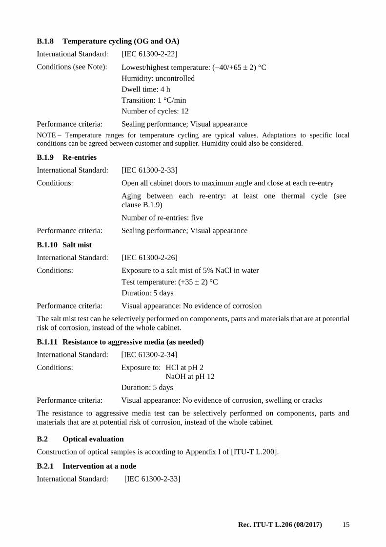
B.1.8 Temperature cycling (OG and OA)
International Standard: [IEC 61300-2-22]
Conditions (see Note): Lowest/highest temperature: (−40/+65 2) °C
Humidity: uncontrolled
Dwell time: 4 h
Transition: 1 °C/min
Number of cycles: 12
Performance criteria: Sealing performance; Visual appearance
NOTE – Temperature ranges for temperature cycling are typical values. Adaptations to specific local
conditions can be agreed between customer and supplier. Humidity could also be considered.
B.1.9 Re-entries
International Standard: [IEC 61300-2-33]
Conditions: Open all cabinet doors to maximum angle and close at each re-entry
Aging between each re-entry: at least one thermal cycle (see
clause B.1.9)
Number of re-entries: five
Performance criteria: Sealing performance; Visual appearance
B.1.10 Salt mist
International Standard: [IEC 61300-2-26]
Conditions:
Exposure to a salt mist of 5% NaCl in water
Test temperature: (+35 2) °C
Duration: 5 days
Performance criteria: Visual appearance: No evidence of corrosion
The salt mist test can be selectively performed on components, parts and materials that are at potential
risk of corrosion, instead of the whole cabinet.
B.1.11 Resistance to aggressive media (as needed)
International Standard: [IEC 61300-2-34]
Conditions: Exposure to: HCl at pH 2
NaOH at pH 12
Duration: 5 days
Performance criteria: Visual appearance: No evidence of corrosion, swelling or cracks
The resistance to aggressive media test can be selectively performed on components, parts and
materials that are at potential risk of corrosion, instead of the whole cabinet.
B.2 Optical evaluation
Construction of optical samples is according to Appendix I of [ITU-T L.200].
B.2.1 Intervention at a node
International Standard: [IEC 61300-2-33]

16 Rec. ITU-T L.206 (08/2017)
Conditions: Execute all manipulations that will normally occur for this product
during an intervention after initial installation. A list of typical
manipulations can be found in Appendix II of [ITU-T L.200]
Performance criteria: Visual appearance; Static: Change in attenuation (residual loss)
Dynamic: Transient loss
B.2.2 Vibration
International Standard: [IEC 61300-2-1]
Conditions: Sweep range: (5-500) Hz sinusoidal at 1 octave/min
Crossover frequency: 9 Hz
– amplitude below 9 Hz: 1.2 mm
– acceleration above 9 Hz: 4 m/s2 (~0.4g)
Direction: three mutually perpendicular axes
Duration: 10 cycles (5-500-5) Hz/axis
Performance criteria: Visual appearance
Static: Change in attenuation (residual loss)
Dynamic: Transient loss
B.2.3 Shock
International Standard: [IEC 61300-2-9]
Conditions: Wave form: Half sine
Duration: 11 ms
Acceleration: 50 m/s2 (~5g)
Direction: three mutually perpendicular axes
Number of shocks: three up and three down per axis
Performance criteria: Visual appearance
Static: Change in attenuation (residual loss)
Dynamic: Transient loss
B.2.4 Temperature cycling (OG and OA)
International Standard: [IEC 61300-2-22]
Conditions (see Note): Lowest/highest temperature: (−40/+65 2) °C
Humidity: uncontrolled
Dwell time: 4 h
Transition: 1 °C/min
Number of cycles: 12
Performance criteria Visual appearance
Static: Change in attenuation (excursion and residual loss)
NOTE – Temperature ranges for temperature cycling are typical values. Adaptations to specific local
conditions can be agreed between customer and supplier. Humidity could also be considered.
Rec. ITU-T L.206 (08/2017) 17
Appendix I
Sample illustrations of cabinet structure
(This appendix does not form an integral part of this Recommendation.)
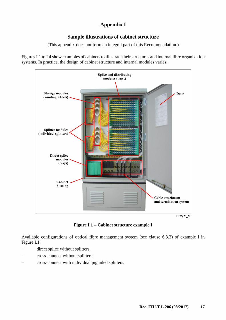
Figures I.1 to I.4 show examples of cabinets to illustrate their structures and internal fibre organization
systems. In practice, the design of cabinet structure and internal modules varies.
Figure I.1 – Cabinet structure example I
Available configurations of optical fibre management system (see clause 6.3.3) of example I in
Figure I.1:
– direct splice without splitters;
– cross-connect without splitters;
– cross-connect with individual pigtailed splitters.

18 Rec. ITU-T L.206 (08/2017)
Figure I.2 – Cabinet structure example II
Available configurations of optical fibre management system (see clause 6.3.3) of example II in
Figure I.2:
– direct splice without splitters;
– cross-connect with individual splitters integrated in distribution modules.
Rec. ITU-T L.206 (08/2017) 19
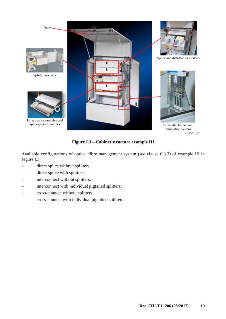
Figure I.3 – Cabinet structure example III
Available configurations of optical fibre management system (see clause 6.3.3) of example III in
Figure I.3:
– direct splice without splitters;
– direct splice with splitters;
– interconnect without splitters;
– interconnect with individual pigtailed splitters;
– cross-connect without splitters;
– cross-connect with individual pigtailed splitters.
20 Rec. ITU-T L.206 (08/2017)
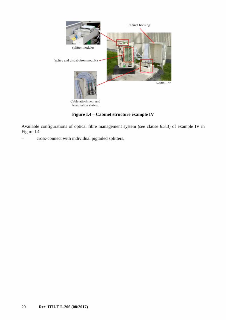
Figure I.4 – Cabinet structure example IV
Available configurations of optical fibre management system (see clause 6.3.3) of example IV in
Figure I.4:
– cross-connect with individual pigtailed splitters.

Rec. ITU-T L.206 (08/2017) 21
Appendix II
Product characterization checklist
(This appendix does not form an integral part of this Recommendation.)
This checklist facilitates the systematic characterization of the features and capabilities of an optical
cross-connect cabinet. It reflects the parameters that are described in [ITU-T L.200]. It may be useful
for preparation of the test programme of products as well as product descriptions for tenders and
purchasing specifications, comparison of different or competitive products and creation of
commercial information and ordering guides.
Product name: ....................................................
Material of cabinet housing
Metal
SMC
Other: …….......................................................
Application environment(s) (see clause 7.1 of [ITU-T L.200])
OG Outdoor ground level
OA Above ground level
E Extreme (describe differences versus a basic environmental class)
Ingress protection (IP) protection class
IP54
IP55
Other: …….......................................................
Optical functionality and compatibility (see clause 6 of [ITU-T L.200])
– optical stability level:
Static
Dynamic (transient free)
– wavelength (see clause 6.3 of [ITU-T L.200])
1 310 nm
1 550 nm
1 625 nm
Other: …….......................................................
22 Rec. ITU-T L.206 (08/2017)
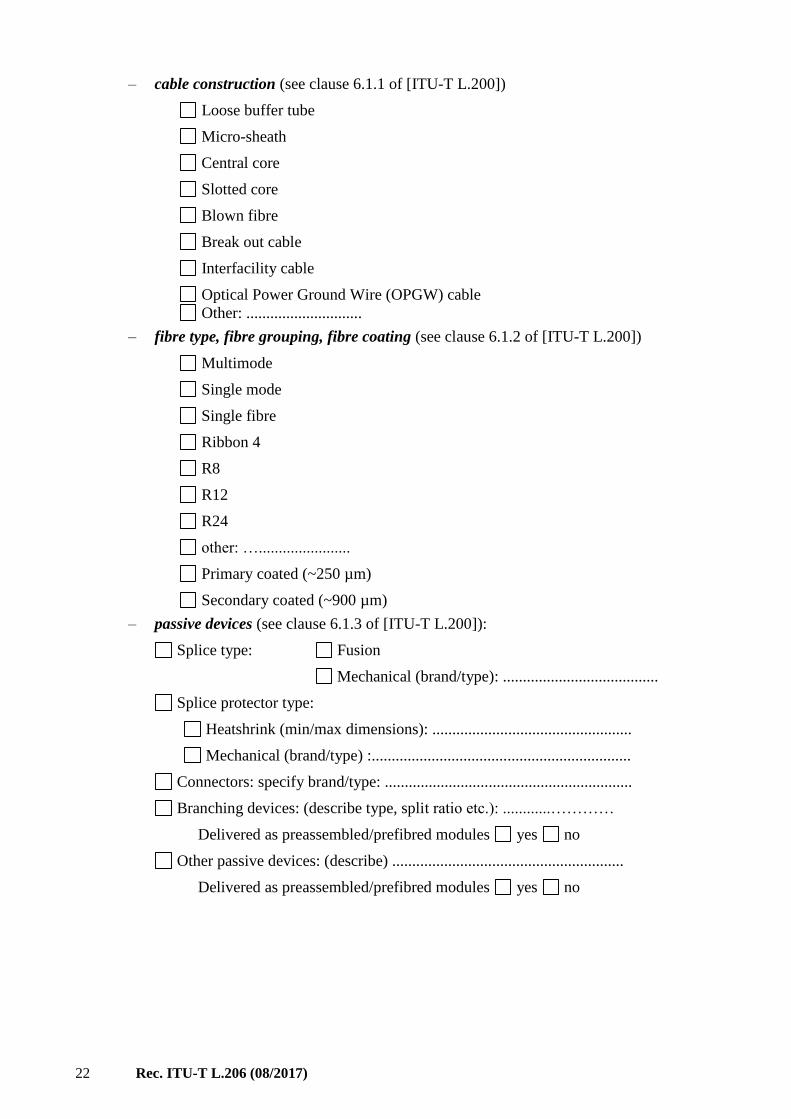
– cable construction (see clause 6.1.1 of [ITU-T L.200])
Loose buffer tube
Micro-sheath
Central core
Slotted core
Blown fibre
Break out cable
Interfacility cable
Optical Power Ground Wire (OPGW) cable
Other: .............................
– fibre type, fibre grouping, fibre coating (see clause 6.1.2 of [ITU-T L.200])
Multimode
Single mode
Single fibre
Ribbon 4
R8
R12
R24
other: ….......................
Primary coated (~250 µm)
Secondary coated (~900 µm)
– passive devices (see clause 6.1.3 of [ITU-T L.200]):
Splice type: Fusion
Mechanical (brand/type): .......................................
Splice protector type:
Heatshrink (min/max dimensions): ..................................................
Mechanical (brand/type) :.................................................................
Connectors: specify brand/type: ..............................................................
Branching devices: (describe type, split ratio etc.): ............…………
Delivered as preassembled/prefibred modules yes no
Other passive devices: (describe) ..........................................................
Delivered as preassembled/prefibred modules yes no
Rec. ITU-T L.206 (08/2017) 23
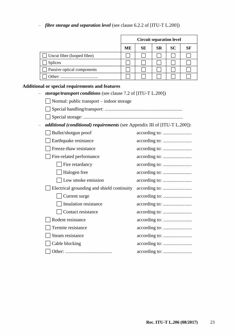
– fibre storage and separation level (see clause 6.2.2 of [ITU-T L.200])
Circuit separation level
ME SE SR SC SF
Uncut fibre (looped fibre)
Splices
Passive optical components
Other: ..................................
Additional or special requirements and features
– storage/transport conditions (see clause 7.2 of [ITU-T L.200])
Normal: public transport – indoor storage
Special handling/transport: .................................................................
Special storage: ...................................................................................
– additional (conditional) requirements (see Appendix III of [ITU-T L.200]):
Bullet/shotgun proof according to: ........................
Earthquake resistance according to: ........................
Freeze-thaw resistance according to: ........................
Fire-related performance according to: ........................
Fire retardancy according to: ........................
Halogen free according to: ........................
Low smoke emission according to: ........................
Electrical grounding and shield continuity according to: ........................
Current surge according to: ........................
Insulation resistance according to: ........................
Contact resistance according to: ........................
Rodent resistance according to: ........................
Termite resistance according to: ........................
Steam resistance according to: ........................
Cable blocking according to: ........................
Other: ....................................... according to: ........................
24 Rec. ITU-T L.206 (08/2017)
Bibliography
[b-ITU-T G-Sup.59] ITU-T G-series Recommendations – Supplement 59 (2016), Guidance
on optical fibre and cable reliability.

Printed in Switzerland Geneva, 2017
SERIES OF ITU-T RECOMMENDATIONS
Series A Organization of the work of ITU-T
Series D Tariff and accounting principles and international telecommunication/ICT economic and
policy issues
Series E Overall network operation, telephone service, service operation and human factors
Series F Non-telephone telecommunication services
Series G Transmission systems and media, digital systems and networks
Series H Audiovisual and multimedia systems
Series I Integrated services digital network
Series J Cable networks and transmission of television, sound programme and other multimedia
signals
Series K Protection against interference
Series L Environment and ICTs, climate change, e-waste, energy efficiency; construction,
installation and protection of cables and other elements of outside plant
Series M Telecommunication management, including TMN and network maintenance
Series N Maintenance: international sound programme and television transmission circuits
Series O Specifications of measuring equipment
Series P Telephone transmission quality, telephone installations, local line networks
Series Q Switching and signalling, and associated measurements and tests
Series R Telegraph transmission
Series S Telegraph services terminal equipment
Series T Terminals for telematic services
Series U Telegraph switching
Series V Data communication over the telephone network
Series X Data networks, open system communications and security
Series Y Global information infrastructure, Internet protocol aspects, next-generation networks,
Internet of Things and smart cities
Series Z Languages and general software aspects for telecommunication systems