Embed Size (px)
Citation preview
)45 4 8����TELECOMMUNICATION (07/94)STANDARDIZATION SECTOROF ITU
$!4!��.%47/2+3��!.$��/0%.��3934%-#/--5.)#!4)/.3
/0%.��3934%-3��).4%2#/..%#4)/.�� ��-/$%,!.$��./4!4)/.
).&/2-!4)/.��4%#(./,/'9��/0%.��3934%-3��).4%2#/..%#4)/.��"!3)#��2%&%2%.#%��-/$%,�4(%��"!3)#��-/$%,
)45 4��2ECOMMENDATION��8����
(Previously “CCITT Recommendation”)
INTERNATIONAL TELECOMMUNICATION UNION
Foreword
ITU (International Telecommunication Union) is the United Nations Specialized Agency in the field oftelecommunications. The ITU Telecommunication Standardization Sector (ITU-T) is a permanent organ of the ITU.Some 179 member countries, 84 telecom operating entities, 145 scientific and industrial organizations and38 international organizations participate in ITU-T which is the body which sets world telecommunications standards(Recommendations).
The approval of Recommendations by the Members of ITU-T is covered by the procedure laid down in WTSCResolution No. 1 (Helsinki, 1993). In addition, the World Telecommunication Standardization Conference (WTSC),which meets every four years, approves Recommendations submitted to it and establishes the study programme for thefollowing period.
In some areas of information technology which fall within ITU-T’s purview, the necessary standards are prepared on acollaborative basis with ISO and IEC. The text of ITU-T Recommendation X.200 was approved on 1st of July 1994. Theidentical text is also published as ISO/IEC International Standard 7498-1.
___________________
NOTE
In this Recommendation, the expression “Administration” is used for conciseness to indicate both a telecommunicationadministration and a recognized operating agency.
ITU 1994
All rights reserved. No part of this publication may be reproduced or utilized in any form or by any means, electronic ormechanical, including photocopying and microfilm, without permission in writing from the ITU.
ITU-T Rec. X.200 (1994 E) i
CONTENTSITU-T Rec. X.200 (1994 E)
Page
1 Scope.............................................................................................................................................................. 1
2 Definitions...................................................................................................................................................... 2
3 Notation.......................................................................................................................................................... 2
4 Introduction to Open Systems Interconnection (OSI) .................................................................................... 24.1 Definitions........................................................................................................................................... 24.2 Open System Interconnection Environment ....................................................................................... 34.3 Modelling the OSI Environment......................................................................................................... 4
5 Concepts of a layered architecture ................................................................................................................. 55.1 Introduction......................................................................................................................................... 55.2 Principles of layering .......................................................................................................................... 65.3 Communication between peer-entities ................................................................................................ 95.4 Identifiers ............................................................................................................................................ 135.5 Properties of service-access-points ..................................................................................................... 145.6 Data-units............................................................................................................................................ 155.7 The nature of the (N)-service .............................................................................................................. 165.8 Elements of layer operation ................................................................................................................ 165.9 Routing................................................................................................................................................ 275.10 Quality Of Service (QOS)................................................................................................................... 27
6 Introduction to the specific OSI layers........................................................................................................... 286.1 Specific layers ..................................................................................................................................... 286.2 The principles used to determine the seven layers in the Reference Model ....................................... 296.3 Layer descriptions ............................................................................................................................... 306.4 Combinations of connection-mode and connectionless-mode............................................................ 306.5 Configurations of OSI Open Systems ................................................................................................. 31
7 Detailed description of the resulting OSI architecture ................................................................................... 327.1 Application Layer ............................................................................................................................... 327.2 Presentation Layer .............................................................................................................................. 337.3 Session Layer ...................................................................................................................................... 347.4 Transport Layer................................................................................................................................... 377.5 Network Layer .................................................................................................................................... 417.6 Data Link Layer .................................................................................................................................. 467.7 Physical Layer..................................................................................................................................... 49
8 Management aspects of OSI........................................................................................................................... 528.1 Definitions........................................................................................................................................... 528.2 Introduction......................................................................................................................................... 538.3 Categories of management activities................................................................................................... 538.4 Principles for positioning management functions............................................................................... 54
9 Compliance and Consistency with this reference model................................................................................ 549.1 Definitions........................................................................................................................................... 549.2 Application of consistency and compliance requirements .................................................................. 55
Annex A – Brief explanation of how the layers were chosen ................................................................................ 56
Annex B – Alphabetical index to definitions ......................................................................................................... 57

ii ITU-T Rec. X.200 (1994 E)
Summary
This reference model provides a common basis for the coordination of standards development for the purpose of systemsinterconnection, while allowing existing standards to be placed into perspective within the overall reference model. Italso identifies areas for developing and improving standards and provides a common reference for maintainingconsistency among all related standards. The text was developed jointly with ISO/IEC and the main intent of thisrevision is to introduce the joint text, which incorporates inclusion of the concept of connectionless transmission, inaddition to a number of technical and editorial refinements.
ISO/IEC 7498-1 : 1994(E)
ITU-T Rec. X.200 (1994 E) 1
INTERNATIONAL STANDARDISO/IEC 7498-1 : 1994(E)
ITU-T Rec. X.200 (1994 E)
CCITT RECOMMENDATION
INFORMATION TECHNOLOGY – OPEN SYSTEMS INTERCONNECTION –BASIC REFERENCE MODEL: THE BASIC MODEL
1 Scope
1.1 The purpose of this Reference Model of Open Systems Interconnection is to provide a common basis for thecoordination of standards development for the purpose of systems interconnection, while allowing existing standards tobe placed into perspective within the overall Reference Model.
1.2 The term Open Systems Interconnection (OSI) qualifies standards for the exchange of information amongsystems that are “open” to one another for this purpose by virtue of their mutual use of the applicable standards.
1.3 The fact that a system is open does not imply any particular systems implementation, technology or means ofinterconnection, but refers to the mutual recognition and support of the applicable standards.
1.4 It is also the purpose of this Reference Model to identify areas for developing or improving standards, and toprovide a common reference for maintaining consistency of all related standards. It is not the intent of this ReferenceModel either to serve as an implementation specification, or to be a basis for appraising the conformance of actualimplementations, or to provide a sufficient level of detail to define precisely the services and protocols of theinterconnection architecture. Rather, this Reference Model provides a conceptual and functional framework whichallows international teams of experts to work productively and independently on the development of standards for eachlayer of the Reference Model for OSI.
1.5 The Reference Model has sufficient flexibility to accommodate advances in technology and expansion in userdemands. This flexibility is also intended to allow the phased transition from existing implementations to OSI standards.
1.6 While the scope of the general architectural principles required for OSI is very broad, this Reference Model isprimarily concerned with systems comprising terminals, computers, and associated devices and the means fortransferring information between such systems. Other aspects of OSI requiring attention are described briefly (see 4.2).
1.7 The description of the Basic Reference Model of OSI is developed in stages:
1.8 Clause 4 establishes the reasons for Open Systems Interconnection, defines what is being connected, the scopeof the interconnection, and describes the modelling principles used in OSI.
1.9 Clause 5 describes the general nature of the architecture of the Reference Model; namely that it is layered,what layering means, and the principles used to describe layers.
1.10 Clause 6 names, and introduces the specific layers of the architecture.
1.11 Clause 7 provides the description of the specific layers.
1.12 Clause 8 provides the description of Management Aspects of OSI.
1.13 Clause 9 specifies compliance and consistency with the OSI Reference Model.
1.14 An indication of how the layers were chosen is given in Annex A to this Basic Reference Model.
1.15 Additional aspects of this Reference Model beyond the basic aspects are described in several parts. The firstpart describes the Basic Reference Model. The second part describes the architecture for OSI Security. The third partdescribes OSI Naming and Addressing. The fourth describes OSI System Management.
1.16 The Basic Reference Model serves as a framework for the definition of services and protocols which fit withinthe boundaries established by the Reference Model.
1.17 In those few cases where a feature is explicitly marked (optional) in the Basic Reference Model it shouldremain optional in the corresponding service or protocol (even if at a given instant the two cases of the option are not yetdocumented).
ISO/IEC 7498-1 : 1994(E)
2 ITU-T Rec. X.200 (1994 E)
1.18 This Reference Model does not specify services and protocols for OSI. It is neither an implementationspecification for systems, nor a basis for appraising the conformance of implementations.
1.19 For standards which meet the OSI requirements, a small number of practical subsets are defined from optionalfunctions, to facilitate implementation and compatibility.
2 Definitions
Definitions of terms are included at the beginning of individual clauses and sub-clauses. An index of these terms isprovided in Annex B for easy reference.
3 Notation
3.1 Layers are introduced in clause 5. An (N)-, (N+1)- and (N–1)- notation is used to identify and relate adjacentlayers:
(N)-layer: any specific layer;
(N+1)-layer: the next higher layer;
(N–1)-layer: the next lower layer.
This notation is also used for other concepts in the model which are related to these layers, for example (N)-protocol,(N+1)-service.
3.2 Clause 6 introduces names for individual layers. When referring to these layers by name, the (N)-, (N+1)-and (N–1)- prefixes are replaced by the names of the layers, for example transport-protocol, session-entity, andnetwork-service.
4 Introduction to Open Systems Interconnection (OSI)NOTE – The general principles described in clauses 4 and 5 hold for all layers of the Reference Model, unless layer
specific statements to the contrary are made in clauses 6 and 7.
4.1 Definitions
4.1.1 real system: A set of one or more computers, the associated software, peripherals, terminals, humanoperators, physical processes, information transfer means, etc., that forms an autonomous whole capable of performinginformation processing and/or information transfer.
4.1.2 real open system: A real system which complies with the requirements of OSI standards in itscommunication with other real systems.
4.1.3 open system: The representation within the Reference Model of those aspects of a real open system that arepertinent to OSI.
4.1.4 application process: An element within a real open system which performs the information processing for aparticular application.
4.1.5 Open System Interconnection Environment (OSIE): An abstract representation of the set of concepts,elements, functions, services, protocols, etc., as defined by the OSI Reference Model and the derived specific standardswhich, when applied, enable communications among open systems.
4.1.6 Local System Environment (LSE): An abstract representation of that part of the real system that is notpertinent to OSI.
NOTE – The LSE may include functions necessary for non-OSI communication.
4.1.7 application-process-invocation: A specific utilization of part or all of the capabilities of a given applicationprocess in support of a specific occasion of information processing.
4.1.8 application-process-type: A description of a class of application processes in terms of a set of informationprocessing capabilities.
ISO/IEC 7498-1 : 1994(E)
ITU-T Rec. X.200 (1994 E) 3
4.2 Open System Interconnection Environment
4.2.1 In the concept of OSI, a real system is a set of one or more computers, associated software, peripherals,terminals, human operators, physical processes, information transfer means, etc., that forms an autonomous wholecapable of performing information processing and/or information transfer.
4.2.2 An application process is an element within a real open system which performs the information processing fora particular application.
4.2.3 Application processes can represent manual processes, computerized processes or physical processes.
4.2.4 Some examples of application processes that are applicable to this open system definition are the following:
a) a person operating a banking terminal is a manual application-process;
b) a FORTRAN program executing in a computer center and accessing a remote database is a computerizedapplication-process; the remote database management systems server is also an application-process; and
c) a process control program executing in a dedicated computer attached to some industrial equipment andlinked into a plant control system is a physical application-process.
4.2.5 An application process represents a set of resources, including processing resources, within a real open systemthat may be used to perform a particular information processing activity. An application process may organize itsinteractions with other application processes in whatever way is necessary to achieve a particular information processinggoal: no constraints are imposed by this Reference Model either on the form of these interactions or on the possiblerelationships that may exist between them.
4.2.6 The activity of a given application process is represented by one or more application process invocations.Cooperation between application processes takes place via relationships established among application processinvocations. At a particular time, an application process may be represented by none, one or more application processinvocations. An application process invocation is responsible for coordinating its interactions with other applicationprocess invocations. Such coordination is outside the scope of this Reference Model.
4.2.7 OSI is concerned with the exchange of information between open systems (and not the internal functioning ofeach individual real open system).
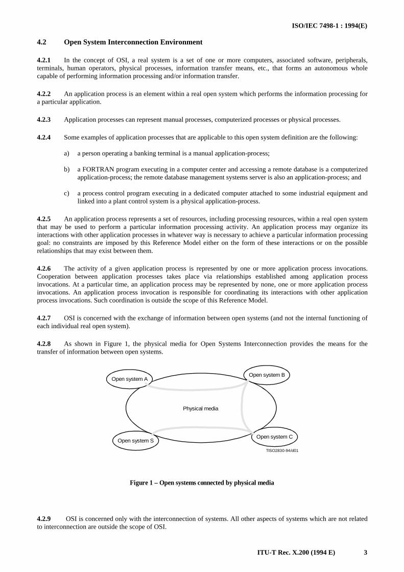
4.2.8 As shown in Figure 1, the physical media for Open Systems Interconnection provides the means for thetransfer of information between open systems.
TISO2830-94/d01
Open system AOpen system B
Open system SOpen system C
Physical media
Figure 1 – Open systems connected by physical media
FIGURE 1/X.200...[D01] = 6.5 CM
4.2.9 OSI is concerned only with the interconnection of systems. All other aspects of systems which are not relatedto interconnection are outside the scope of OSI.
ISO/IEC 7498-1 : 1994(E)
4 ITU-T Rec. X.200 (1994 E)
4.2.10 OSI is concerned not only with the transfer of information between systems, i.e. transmission, but also withtheir capability to interwork to achieve a common (distributed) task. In other words, OSI is concerned with theinterconnection aspects of cooperation1) between systems, which is implied by the expression “systems interconnection.”
4.2.11 The objective of OSI is to define a set of standards to enable real open systems to cooperate. A system whichcomplies with the requirements of applicable OSI standards in its cooperation with other systems is termed a real opensystem.
4.2.12 The design intent of the OSI standards is to specify a set of standards that make it possible for autonomoussystems to communicate. Any equipment which communicates in conformance with all applicable OSI protocolstandards is a real world equivalent of the model concept “open system”. Equipment that is in the “terminal” category,that is, one that requires human intervention for the dominant parts of information processing, may satisfy the conditionsof the previous sentences when the appropriate OSI standards are employed in communication with other open systems.
4.3 Modelling the OSI Environment
4.3.1 The development of OSI standards, i.e. standards for the interconnection of real open systems, is assisted bythe use of abstract models. To specify the external behavior of interconnected real open systems, each real open systemis replaced by a functionally equivalent abstract model of a real open system called an open system. Only theinterconnection aspects of these open systems would strictly need to be described. However to accomplish this, it isnecessary to describe both the internal and external behavior of these open systems. Only the external behavior of opensystems is retained for the definition of standards for real open systems. The description of the internal behavior of opensystems is provided in the Basic Reference Model only to support the definition of the interconnection aspects. Any realsystem which behaves externally as an open system can be considered to be a real open system.
4.3.2 This abstract modelling is used in two steps.
4.3.3 First, basic elements of open systems and some key decisions concerning their organization and functioning,are developed. This constitutes the Basic Reference Model of Open Systems Interconnection described in thisRecommendation | Part of this International Standard.
4.3.4 Then, the detailed and precise description of the functioning of the open system is developed in the frameworkformed by the Basic Reference Model. This constitutes the services and protocols for OSI which are the subject of otherRecommendations and/or International Standards.
4.3.5 It should be emphasized that the Basic Reference Model does not, by itself, specify the detailed and precisefunctioning of the open system and, therefore, it does not specify the external behavior of real open systems and does notimply the structure of the implementation of a real open system.
4.3.6 The reader not familiar with the technique of abstract modelling is cautioned that those concepts introduced inthe description of open systems constitute an abstraction despite a similiar appearance to concepts commonly found inreal systems. Therefore, real open systems need not be implemented as described by the Model.
_______________1) Cooperation among open systems involves a broad range of activities of which the following have been identified:
a) interprocess communication, which concerns the exchange of information and the synchronization of activitybetween OSI application processes;
b) data representation, which concerns all aspects of the creation and maintenance of data descriptions and datatransformations for reformatting data exchanged between open systems;
c) data storage, which concerns storage media, and file and database systems for managing and providing access to datastored on the media;
d) process and resource management, which concerns the means by which OSI application processes are declared,initiated and controlled, and the means by which they acquire OSI resources;
e) integrity and security, which concern information processing constraints that have to be preserved or assured duringthe operation of the open systems; and
f) program support, which concerns the definition, compilation, linking, testing, storage, transfer, and access to theprograms executed by OSI application-processes.
Some of these activities may imply exchange of information between the interconnected open systems and their interconnectionaspects may, therefore, be of concern to OSI.
This Basic Reference Model covers the elements of OSI aspects of these activities which are essential for early development of OSIstandards.
ISO/IEC 7498-1 : 1994(E)
ITU-T Rec. X.200 (1994 E) 5
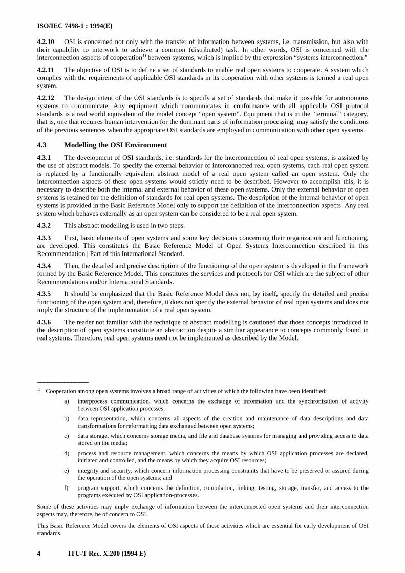
4.3.7 Throughout the remainder of this Basic Reference Model, only the aspects of real systems and application-processes which lie within the OSI Environment (OSIE) are considered. Their interconnection is illustrated throughoutthis Reference Model as depicted in Figure 2.
4.3.8 The extent of the application of the OSIE concept through the use of OSI standards may result in subsets of theOSIE which corresponds to partially disjoint sets of real open systems, which are not physically capable of OSIcommunication between them.
TISO2840-94/d02
Aspects of application-processes of concern to OSI,i.e. applications-entities (see 7.1)
Open system A Open system B Open system C Open system S
Physical media for OSI Associations
Aspects of realopen systems ofconcern to OSI
Figure 2 – Basic elements of OSI
FIGURE 2/X.200...[D02] = 11.5 CM
5 Concepts of a layered architecture
5.1 Introduction
5.1.1 Clause 5 sets forth the architectural concepts that are applied in the development of the Reference Model ofOpen Systems Interconnection. Firstly, the concept of a layered architecture (with layers, entities, service-access-points,protocols, connections, etc.) is described. Secondly, identifiers are introduced for entities, service-access-points, andconnections. Thirdly, service-access-points and data-units are described. Fourthly, elements of layer operation aredescribed including connections, transmission of data, and error functions. Then, routing aspects are introduced andfinally, management aspects are discussed.
5.1.2 The concepts described in clause 5 are those required to describe the Reference Model of Open SystemsInterconnection. However, not all of the concepts described are employed in each layer of the Reference Model.
ISO/IEC 7498-1 : 1994(E)
6 ITU-T Rec. X.200 (1994 E)
5.1.3 Four elements are basic to the Reference Model (see Figure 2):
a) open systems;
b) the application-entities which exist within the OSI Environment (see 7.1);
c) the associations (see 5.3) which join the application-entities and permit them to exchange information;and
d) the physical media for OSI.
NOTE – Security aspects which are also general architectural elements of protocols are discussed in CCITT Rec. X.800 |ISO 7498-2.
5.2 Principles of layering
5.2.1 Definitions
5.2.1.1 (N)-subsystem: An element in a hierarchical division of an open system which interacts directly only withelements in the next higher division or the next lower division of that open system.
5.2.1.2 (N)-layer: A subdivision of the OSI architecture, constituted by subsystems of the same rank (N).
5.2.1.3 peer-(N)-entities: Entities within the same (N)-layer.
5.2.1.4 sublayer: A subdivision of a layer.
5.2.1.5 (N)-service: A capability of the (N)-layer and the layers beneath it, which is provided to (N+1)-entities at theboundary between the (N)-layer and the (N+1)-layer.
5.2.1.6 (N)-facility: A part of an (N)-service.
5.2.1.7 (N)-function: A part of the activity of (N)-entities.
5.2.1.8 (N)-service-access-point, (N)-SAP: The point at which (N)-services are provided by an (N)-entity to an(N+1)-entity.
5.2.1.9 (N)-protocol: A set of rules and formats (semantic and syntactic) which determines the communicationbehavior of (N)-entities in the performance of (N)-functions.
5.2.1.10 (N)-entity-type: A description of a class of (N)-entities in terms of a set of capabilities defined for the(N)-layer.
5.2.1.11 (N)-entity: An active element within an (N)-subsystem embodying a set of capabilities defined for the(N)-layer that corresponds to a specific (N)-entity-type (without any extra capabilities being used).
5.2.1.12 (N)-entity-invocation: A specific utilization of part or all of the capabilities of a given (N)-entity (withoutany extra capabilities being used).
5.2.2 Description
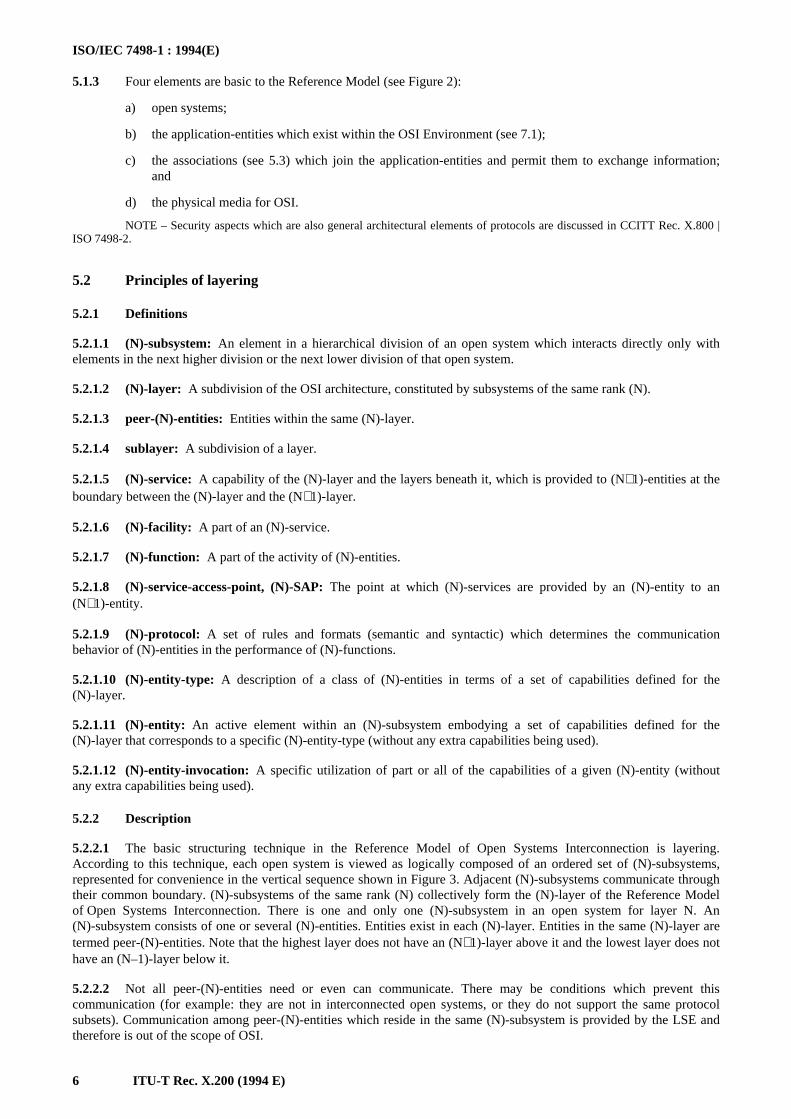
5.2.2.1 The basic structuring technique in the Reference Model of Open Systems Interconnection is layering.According to this technique, each open system is viewed as logically composed of an ordered set of (N)-subsystems,represented for convenience in the vertical sequence shown in Figure 3. Adjacent (N)-subsystems communicate throughtheir common boundary. (N)-subsystems of the same rank (N) collectively form the (N)-layer of the Reference Modelof Open Systems Interconnection. There is one and only one (N)-subsystem in an open system for layer N. An(N)-subsystem consists of one or several (N)-entities. Entities exist in each (N)-layer. Entities in the same (N)-layer aretermed peer-(N)-entities. Note that the highest layer does not have an (N+1)-layer above it and the lowest layer does nothave an (N–1)-layer below it.
5.2.2.2 Not all peer-(N)-entities need or even can communicate. There may be conditions which prevent thiscommunication (for example: they are not in interconnected open systems, or they do not support the same protocolsubsets). Communication among peer-(N)-entities which reside in the same (N)-subsystem is provided by the LSE andtherefore is out of the scope of OSI.
ISO/IEC 7498-1 : 1994(E)
ITU-T Rec. X.200 (1994 E) 7
TISO2850-94/d03
Opensystem A
Opensystem B
Opensystem C
Opensystem S
Physical media for OSI
Highest layer
(N + 1)-layer
(N)-layer
(N – 1)-layer
Lowest layer
Figure 3 – Layering in cooperating open systems
FIGURE 3/X.200...[D03] = 10 CM
NOTES
1 The distinction between the type of some object and an instance of that object is a distinction of significance for OSI.A type is a description of a class of objects. An instance of this type is any object that conforms to this description. The instances ofthe same type constitute a class. A type, and any instances of this type can be referred to by an individual name. Each nameableinstance and the type to which this instance belongs carry distinguishable names.
For example, given that a programmer has written a computer program, that programmer has generated a type of somethingwhere instances of that type are created every time that particular program is invoked into execution by a computer. Thus, aFORTRAN compiler is a type and each occasion where a copy of that program is invoked in a data processing machine one displaysan instance of that program.
The general concept of instantiation applies within OSI: Consider now an (N)-entity in the OSI context. It too, has twoaspects, a type and a collection of invocations. The type of an (N)-entity is defined by description of the specific set of (N)-layerfunctions it is able to perform. An invocation of that type of (N)-entity is a specific invocation of whatever it is within the relevantopen system that provides the (N)-layer functions called for by its type for a particular occasion of communication. It follows fromthese observations that (N)-entities refer only to the properties of an association between peer (N)-entities, while an (N)-entity-invocation refers to the specific, dynamic occasions of actual information exchange.
It is important to note that actual communication occurs only between (N)-entity-invocations at all layers. In theconnection-mode (see 5.3.3), it is only at connection establishment time (or its logical equivalent during a recovery process) that(N)-entities are explicitly relevant. An actual connection is always made with a specific (N)-entity-invocation, although the request forconnection is often made to an arbitrary (N)-entity (of a specific type). If an (N)-entity-invocation is aware of the name of itspeer-(N)-entity-invocation, it is able to request another connection to that (N)-entity-invocation.
2 It may be necessary to further divide a layer into small substructures called sublayers and to extend the technique oflayering to cover other dimensions of OSI. A sublayer is defined as a grouping of functions in a layer which may be bypassed. Thebypassing of all the sublayers of a layer is not allowed. A sublayer uses the entities and communication services of the layer. Thedetailed definition or additional characteristics of a sublayer are for further study.
5.2.2.3 Except for the highest layer, each (N)-layer provides (N+1)-entities in the (N+1)-layer with an (N)-service at(N)-SAP(s). The properties of (N)-SAPs are described in 5.5. The highest layer is assumed to represent all possible usesof the (N)-service which are provided by the lower layers.
NOTE – Not all open systems provide the initial source or final destination of data. Such open systems need not contain thehigher layers of the architecture (see Figure 12).
ISO/IEC 7498-1 : 1994(E)
8 ITU-T Rec. X.200 (1994 E)
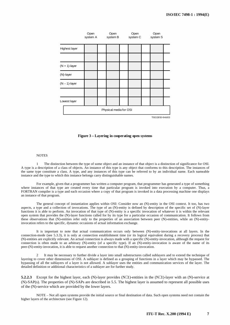
5.2.2.4 Each service provided by an (N)-layer may be tailored by the selection of one or more (N)-facilities whichdetermine the attributes of that service. When a single (N)-entity cannot by itself fully support a service requested by an(N+1)-entity it calls upon the co-operation of other (N)-entities to help complete the service request. In order toco-operate, (N)-entities in any layer, other than those in the lowest layer, communicate by means of the set of servicesprovided by the (N–1)-layer (see Figure 4). The entities in the lowest layer are assumed to communicate directly via thephysical media which connect them.
TISO2860-94/d04
(N + 1)-layer
(N)-layer
(N + 1)-entities
Figure 4 – (N + 1)-entities in the (N + 1)-layercommunicate through the (N)-layer
FIGURE 4/X.200...[D04] = 4.5 CM
5.2.2.5 The services of an (N)-layer are provided to the (N+1)-layer using the (N)-functions performed within the(N)-layer and as necessary the services available from the (N–1)-layer.
NOTE – This does not preclude the case where no protocol action is required in the (N)-layer to support a given(N)-facility because it is already available at the (N–1)-service boundary. However, null functionality of the complete (N)-protocol isnot allowed.
5.2.2.6 An (N)-entity may provide services to one or more (N+1)-entities and use the services of one or more (N–1)-entities. An (N)-service-access-point is the point at which a pair of entities in adjacent layers use or provide services(see Figure 7).
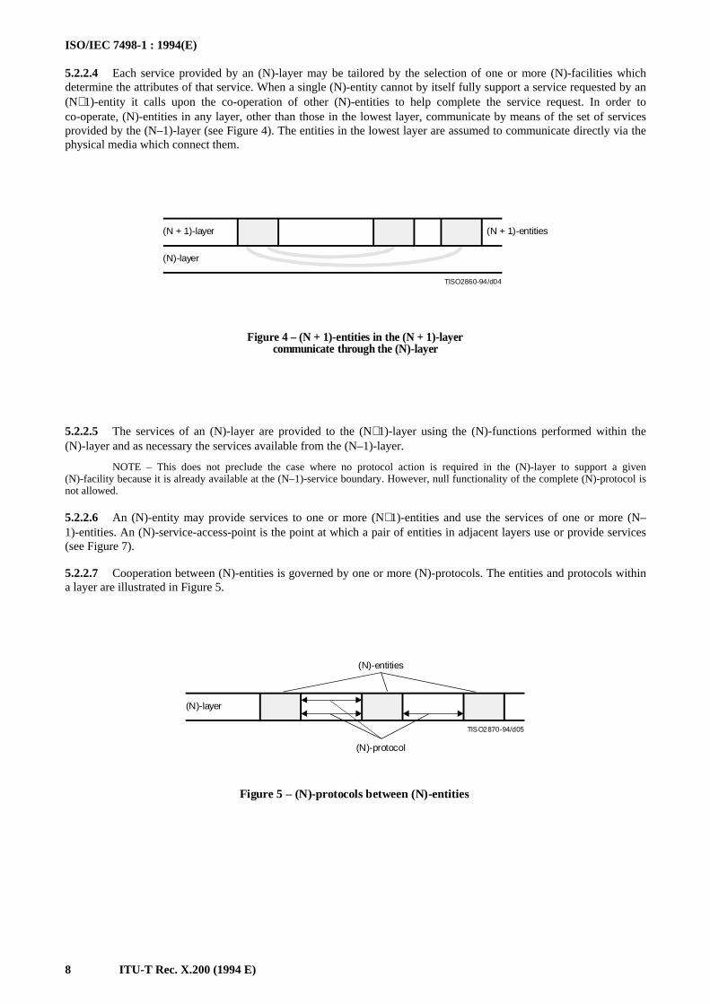
5.2.2.7 Cooperation between (N)-entities is governed by one or more (N)-protocols. The entities and protocols withina layer are illustrated in Figure 5.
TISO2870-94/d05
(N)-entities
(N)-protocol
(N)-layer
Figure 5 – (N)-protocols between (N)-entities
FIGURE 5/X.200...[D06] = 5.5 CM
ISO/IEC 7498-1 : 1994(E)
ITU-T Rec. X.200 (1994 E) 9
5.3 Communication between peer-entities
5.3.1 Definitions
5.3.1.1 (N)-association: A cooperative relationship among (N)-entity-invocations.
5.3.1.2 (N)-connection: An association requested by an (N+1)-entity for the transfer of data betweeen two or more(N+1)-entities. The association is established by the (N)-layer and provides explicit identification of a set of (N)-data-transmissions and agreement concerning the (N)-data-transmission services to be provided for the set.
5.3.1.3 (N)-connection-endpoint: A terminator at one end of an (N)-connection within an (N)-service-access-point.
5.3.1.4 multi-endpoint-connection: A connection with more than two connection-endpoints.
5.3.1.5 correspondent (N)-entities: (N)-entities with an (N–1)-connection between them.
5.3.1.6 (N)-relay: An (N)-function by means of which an (N)-entity forwards data received from one peer-(N)-entityto another peer-(N)-entity.
5.3.1.7 (N)-data-source: An (N)-entity that sends (N–1)-service-data-units (see 5.6.1.7) on an (N–1)-connection.2)
5.3.1.8 (N)-data-sink: An (N)-entity that receives (N–1)-service-data-units on an (N–1)-connnection2)
5.3.1.9 (N)-data-transmission: An (N)-facility which conveys (N)-service-data-units from one (N+1)-entity to oneor more (N+1)-entities.
5.3.1.10 (N)-duplex-transmission: (N)-data-transmission in both directions at the same time.2)
5.3.1.11 (N)-half-duplex-transmission: (N)-data-transmission in either direction, one direction at a time; the choice ofdirection is controlled by an (N+1)-entity.2)
5.3.1.12 (N)-simplex-transmission: (N)-data-transmission in one pre-assigned direction.2)
5.3.1.13 (N)-data-communication: An (N)-function which transfers (N)-protocol-data-units (see 5.6.1.3) according toan (N)-protocol, over one or more (N–1)-connections.2)
5.3.1.14 (N)-two-way-simultaneous-communication: (N)-data-communication in both directions at the same time.
5.3.1.15 (N)-two-way-alternate-communication: (N)-data-communication in both directions, one direction at a time.
5.3.1.16 (N)-one-way-communication: (N)-data-communication in one pre-assigned direction.
5.3.1.17 (N)-connection-mode transmission: (N)-data-transmission in the context of an (N)-connection.
5.3.1.18 (N)-connectionless-mode transmission: (N)-data-transmission not in the context of an (N)-connection andnot required to maintain any logical relationship between (N)-service-data-units.
5.3.2 Description
5.3.2.1 For information to be exchanged between two or more (N+1)-entities, an association is established betweenthem in the (N)-layer using an (N)-protocol.
NOTE – Classes of protocols may be defined within the (N)-protocols.
5.3.2.2 The rules and formats of an (N)-protocol are instantiated in an (N)-subsystem by an (N)-entity. An (N)-entitymay support one or more (N)-protocols. (N)-entities may support (N)-protocols which are connection-mode orconnectionless-mode or both. (N)-entities when supporting connection-mode maintain the binding of (N)-connections tothe appropriate (N+1)-entities at the appropriate (N)-SAPs. (N)-entities when supporting connectionless-mode maintaina binding with the appropriate (N)-SAPs for delivering the connectionless data to the (N+1)-entities.
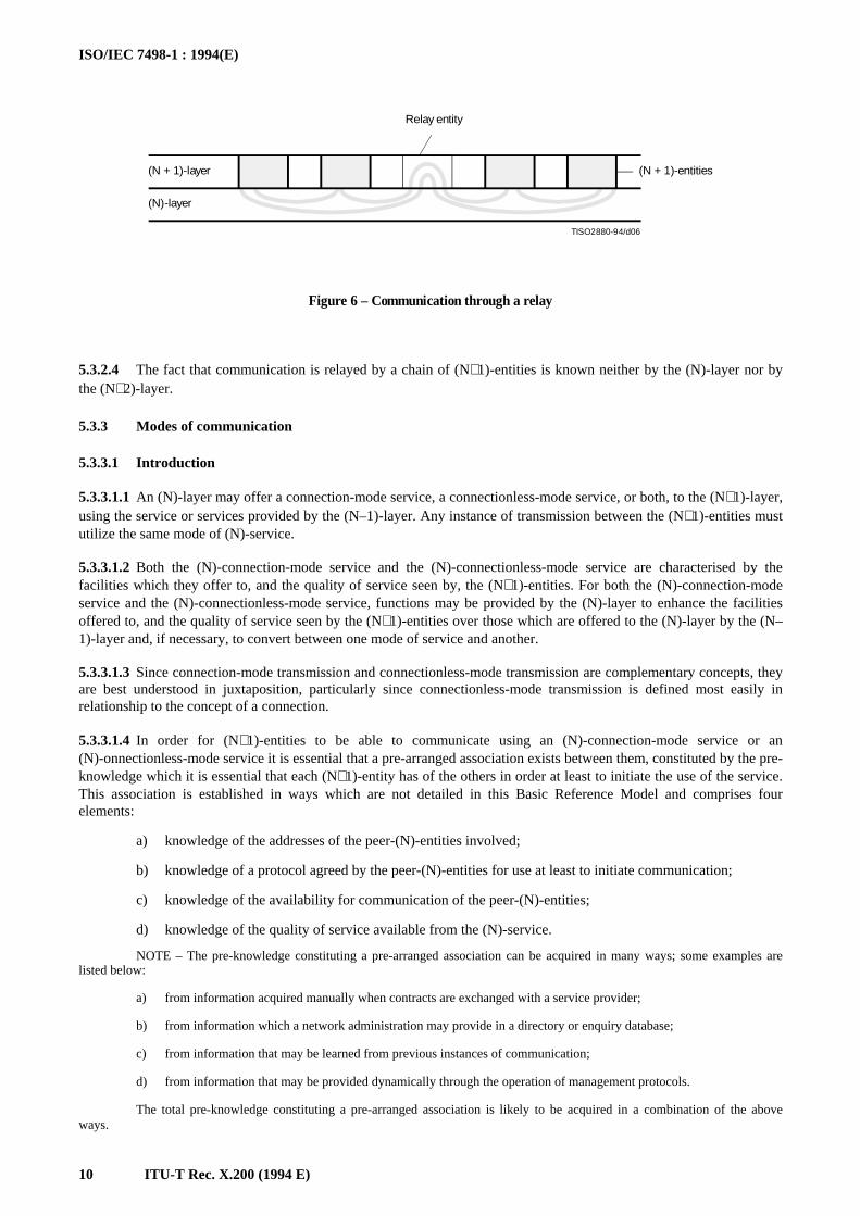
5.3.2.3 (N+1)-entities can communicate only by using the services of the (N)-layer. There are instances where servicesprovided by the (N)-layer do not permit direct access between all of the (N+1)-entities which have to communicate. Ifthis is the case communication can still occur if some other (N+1)-entities can act as relays between them (see Figure 6).
_______________2) These definitions are not for use in this Basic Reference Model, but are for use in other OSI standards.
ISO/IEC 7498-1 : 1994(E)
10 ITU-T Rec. X.200 (1994 E)
TISO2880-94/d06
Relay entity
(N + 1)-entities(N + 1)-layer
(N)-layer
Figure 6 – Communication through a relay
FIGURE 6/X.200...[D06] = 5 CM
5.3.2.4 The fact that communication is relayed by a chain of (N+1)-entities is known neither by the (N)-layer nor bythe (N+2)-layer.
5.3.3 Modes of communication
5.3.3.1 Introduction
5.3.3.1.1 An (N)-layer may offer a connection-mode service, a connectionless-mode service, or both, to the (N+1)-layer,using the service or services provided by the (N–1)-layer. Any instance of transmission between the (N+1)-entities mustutilize the same mode of (N)-service.
5.3.3.1.2 Both the (N)-connection-mode service and the (N)-connectionless-mode service are characterised by thefacilities which they offer to, and the quality of service seen by, the (N+1)-entities. For both the (N)-connection-modeservice and the (N)-connectionless-mode service, functions may be provided by the (N)-layer to enhance the facilitiesoffered to, and the quality of service seen by the (N+1)-entities over those which are offered to the (N)-layer by the (N–1)-layer and, if necessary, to convert between one mode of service and another.
5.3.3.1.3 Since connection-mode transmission and connectionless-mode transmission are complementary concepts, theyare best understood in juxtaposition, particularly since connectionless-mode transmission is defined most easily inrelationship to the concept of a connection.
5.3.3.1.4 In order for (N+1)-entities to be able to communicate using an (N)-connection-mode service or an(N)-onnectionless-mode service it is essential that a pre-arranged association exists between them, constituted by the pre-knowledge which it is essential that each (N+1)-entity has of the others in order at least to initiate the use of the service.This association is established in ways which are not detailed in this Basic Reference Model and comprises fourelements:
a) knowledge of the addresses of the peer-(N)-entities involved;
b) knowledge of a protocol agreed by the peer-(N)-entities for use at least to initiate communication;
c) knowledge of the availability for communication of the peer-(N)-entities;
d) knowledge of the quality of service available from the (N)-service.
NOTE – The pre-knowledge constituting a pre-arranged association can be acquired in many ways; some examples arelisted below:
a) from information acquired manually when contracts are exchanged with a service provider;
b) from information which a network administration may provide in a directory or enquiry database;
c) from information that may be learned from previous instances of communication;
d) from information that may be provided dynamically through the operation of management protocols.
The total pre-knowledge constituting a pre-arranged association is likely to be acquired in a combination of the aboveways.
ISO/IEC 7498-1 : 1994(E)
ITU-T Rec. X.200 (1994 E) 11
5.3.3.2 Connection mode
5.3.3.2.1 A connection is an association established for the transfer of data between two or more peer-(N)-entities. Thisassociation binds the peer-(N)-entities together with the (N–1)-entities in the next lower layer. The ability to establishand release a connection and to transfer data over it is provided to the (N)-entities in a given (N)-layer by the next lowerlayer as a connection-mode service. The use of a connection-mode service by peer-(N)-entities proceeds through threedistinct phases:
a) connection establishment;
b) data transfer; and
c) connection release.
5.3.3.2.2 In addition to the clearly distinguishable lifetime exhibited by these phases,a connection has the followingfundamental characteristics:
a) it involves establishing and maintaining a two or more party agreement concerning the transmission ofdata among the peer-(N)-entities concerned, and using the provider of the (N–1)-service;
b) it allows the negotiation between all the parties concerned of the parameters and options that will governthe transmission of data;
c) it provides connection identification by means of which the overheads involved in address resolution andtransmission can be avoided on data transfers;
d) it provides a context within which successive units of data transmitted between the peer-entities arelogically related, and makes it possible to maintain sequence and provide flow control for thosetransmissions.
5.3.3.2.3 The characteristics of connection-mode transmission are particularly attractive in applications which call forrelatively long-lived, stream-oriented interactions between entities in stable configurations. Examples are provided bydirect terminal use of a remote computer, file transfer, and long-term attachment of remote job entry stations. In thesecases, the entities involved initially discuss their requirements and agree to the terms of their interaction, reservingwhatever resources they may need, transfer a series of related units of data to accomplish their mutual objective, andexplicitly end their interaction, releasing the previously reserved resources. The properties of connection-modetransmission are also relevant in a wide range of other applications.
5.3.3.2.4 Connection-mode transmission is accomplished through the use of (N)-connections. (N)-connections areprovided by the (N)-layer between two or more (N)-service-access-points. The terminator of an (N)-connection at an(N)-service-access-point is called an (N)-connection-endpoint. An (N)-connection is provided by the (N)-layer betweentwo or more (N)-service-access-points at the request of a calling (N+1)-entity in support of the (N+1)-entities attached tothe (N)-service-access-points involved in the (N)-connection. An (N)-connection with more than two endpoints istermed a multi-endpoint-connection. (N)-entities with a connection between them are termed correspondent (N)-entities.
NOTE – Data transfer using an (N)-connection-mode service involves the establishment of an (N)-connection prior to thedata transfer. This dynamically sets up an association between the (N+1)-entities and the (N)-connection-mode service in addition tothe association identified in 5.3.2. This association involves elements which are not part of the pre-arranged association described in5.3.3.1.4, in particular:
a) knowledge of the willingness of the peer-(N)-entity or entities to undertake a specific communication, and of thewillingness of the underlying service to support it and;
b) the ability for the peer-(N)-entities to negotiate and renegotiate the characteristics of the communication.
5.3.3.3 Connectionless mode
5.3.3.3.1 Connectionless-mode transmission is the transmission of a single unit of data from a source service-access-point to one or more destination service-access-points without establishing a connection. A connectionless-mode serviceallows an entity to initiate such a transmission by the performance of a single service access.
5.3.3.3.2 In contrast to a connection, an instance of the use of a connectionless-mode service does not have a clearlydistinguishable lifetime. In addition,t has the following fundamental characteristics:
a) it requires only a pre-arranged association between the peer-(N)-entities involved which determines thecharacteristics of the data to be transmitted, and no dynamic agreement is involved in an instance of theuse of the service;
b) all the information required to deliver a unit of data – destination address, quality of service selection,options, etc. – is presented to the layer providing the connectionless-mode service, together with the unitof data to be transmitted, in a single service access. The layer providing the connectionless-mode serviceis not required to relate this access to any other access.
ISO/IEC 7498-1 : 1994(E)
12 ITU-T Rec. X.200 (1994 E)
5.3.3.3.3 As a result of these fundamental characteristics it may also be true that:
a) each unit of data transmitted is routed independently by the layer providing the connectionless-modeservice; and
b) copies of a unit of data can be transmitted to a number of destination addresses.
5.3.3.3.4 These characteristics of connectionless-mode transmission do not preclude making available to the service userinformation on the nature and quality of service which may apply for a single invocation of the service or which may beobserved over successive invocations of the service between pairs of (N)-service-access-points or among a set of (N)-service-access-points.
5.3.3.3.5 For each layer, the subclauses of clause 7 identify those items which have relevance to the connectionless-mode service provided by that layer.
5.3.3.3.6 The basic (N)-connectionless-mode service is a service which meets the following conditions:
a) it is not required to exhibit any minimum values of the quality of service measures, in particular thesequence of (N)-service-data-units need not be maintained and;
b) it is not required to exhibit peer flow control.
5.3.3.3.7 Any (N)-connectionless-mode service definition should allow the basic service.
5.3.3.3.8 Since the basic service is not required to maintain the sequence of (N)-service-data-units, there is norequirement for any (N)-layer to provide sequencing functions. However, in real implementations the characteristics ofthe underlying medium or of real subnetworks may offer a high probability of in-sequence delivery and this may bereflected in the characteristics of the connectionless-mode services offered by higher layers.
5.3.3.3.9 An (N+1)-entity provides no information to the provider of an (N)-connectionless-mode service about thelogical relationships between (N)-service-data-units, apart from the source and destination (N)-service-access-point-addresses.
5.3.3.3.10 From the point of view of the (N+1)-entity this means that it is not able to require the (N)-service to apply aparticular function to a sequence of (N)-service-data-units sent by it. However, from the point of view of the (N)-layer,this does not imply any constraint on the functions which support the service.
5.3.3.3.11 (N+1)-entities can communicate using an (N)-connectionless-mode service provided that there is a pre-arranged association between them providing knowledge about each other which allows them to do so. This knowledgeshould allow the locations of the (N+1)-entities to be determined, it should determine the correct interpretation of(N)-ervice-data-units by a receiving (N+1)-entity, and it may define the rates of transfer, rates of response, and theprotocol in use between the entities. The knowledge may result from prior agreement between the (N+1)-entitiesconcerning the parameters, formats, and options to be used.
5.3.3.3.12 (N+1)-entities may require prior knowledge of the facilities offered by the service and the quality of servicewhich they can expect to receive from it in order to choose an (N+1)-protocol to be used for communication over an(N)-connectionless-mode service.
5.3.4 The relationship between services provided at adjacent layer boundaries
5.3.4.1 There are no architectural constraints on any vertical combination of an (N)-layer providing one type of(N)-service (connection-mode or connectionless-mode) using the other type of (N–1)-service. In principle the services atthe two layer boundaries can be:
a) both connection-mode services;
b) both connectionless-mode services;
c) the (N)-service a connection-mode service and the (N–1)-service a connectionless-mode service;
d) the (N)-service a connectionless-mode service and the (N–1)-service a connection-mode service.
5.3.4.2 In order to allow combinations c) and d) two architectural elements are required:
a) a function to provide an (N)-connection-mode service using an (N–1)-connectionless-mode service; and
b) a function to provide an (N)-connectionless-mode service using an (N–1)-connection-mode service.
These are known as mode conversion functions.NOTE – Of these functions, function a) requires significant protocol-control-information. For example, there is a need to
identify the connection which is constructed, control its state and provide sequencing of service-data-units. Function b) requires littleor no additional protocol-control-information, rather, it places constraints on the way in which the connection-mode service is used.
ISO/IEC 7498-1 : 1994(E)
ITU-T Rec. X.200 (1994 E) 13
5.3.5 Application of mode conversion functions
5.3.5.1 Mode conversion functions may be invoked in OSI end systems, or in OSI relay systems (see 6.5). Wheninvoked in OSI relay systems, the mode conversion functions may either:
a) join an (N)-protocol using the (N–1)-connectionless service and an (N)-protocol using the (N–1)-connection-mode service in support of an (N)-connection-mode service; or
b) join an (N)-protocol using the (N–1)-connectionless-mode service and an (N)-protocol using the (N–1)-connection-mode service in support of an (N)-connectionless mode service.
5.3.5.2 The use of mode conversions between (N–1)-services within a layer is not explicitly constrained by theReference Model but, where several (N–1)-services are connected in tandem, the use of mode conversions would beordered to minimize the number of mode conversions necessary to arrive at a given composite (N)-service.
5.3.5.3 Where an (N–1)-connectionless-mode service is enhanced to provide a (N)-connection-mode service, anumber of (N)-connections may be supported by (N–1)-connectionless-mode transmission between the same (N–1)-service-access-points.
5.3.5.4 Where an (N–1)-connection-mode service is used to provide an (N)-connectionless-mode service,(N)-connectionless-mode transmission between a number of different (N)-service-access-points may be supported by thesame (N–1)-connection.
5.4 Identifiers
5.4.1 Definitions
5.4.1.1 (N)-address: A name unambiguous within the OSIE which is used to identify a set of (N)-service-access-points which are all located at a boundary between an (N)-subsystem and an (N+1)-subsystem in the same open system.
NOTE – A name is unambiguous within a given scope when it identifies one and only one object within that scope.Unambiguity of a name does not preclude the existence of synonyms.
5.4.1.2 (N)-service-access-point-address; (N)-SAP-address: An (N)-address that is used to identify a single(N)-SAP.
5.4.1.3 (N)-address-mapping: An (N)-function which provides the mapping between the (N)-addresses and the (N–1)-addresses associated with an (N)-entity.
5.4.1.4 routing: A function within a layer which translates the title of an entity or the service-access-point-address towhich the entity is attached into a path by which the entity can be reached.
5.4.1.5 (N)-connection-endpoint-identifier: An identifier of an (N)-connection-endpoint which can be used toidentify the corresponding (N)-connection at an (N)-service-access-point.
5.4.1.6 (N)-connection-endpoint-suffix: A part of an (N)-connection-endpoint-identifier which is unique within thescope of an (N)-service-access-point.
5.4.1.7 multi-connection-endpoint-identifier: An identifier which specifies the connection-endpoint of a multi-endpoint-connection which should accept the data that is being transferred.
5.4.1.8 (N)-service-connection-identifier: An identifier which uniquely specifies an (N)-connection within theenvironment of the correspondent (N+1)-entities.
5.4.1.9 (N)-protocol-connection-identifier: An identifier which uniquely specifies an individual (N)-connectionwithin the environment of the multiplexed (N–1)-connection.
5.4.1.10 (N)-entity-title: A name that is used to identify unambiguously an (N)-entity.
5.4.2 Description
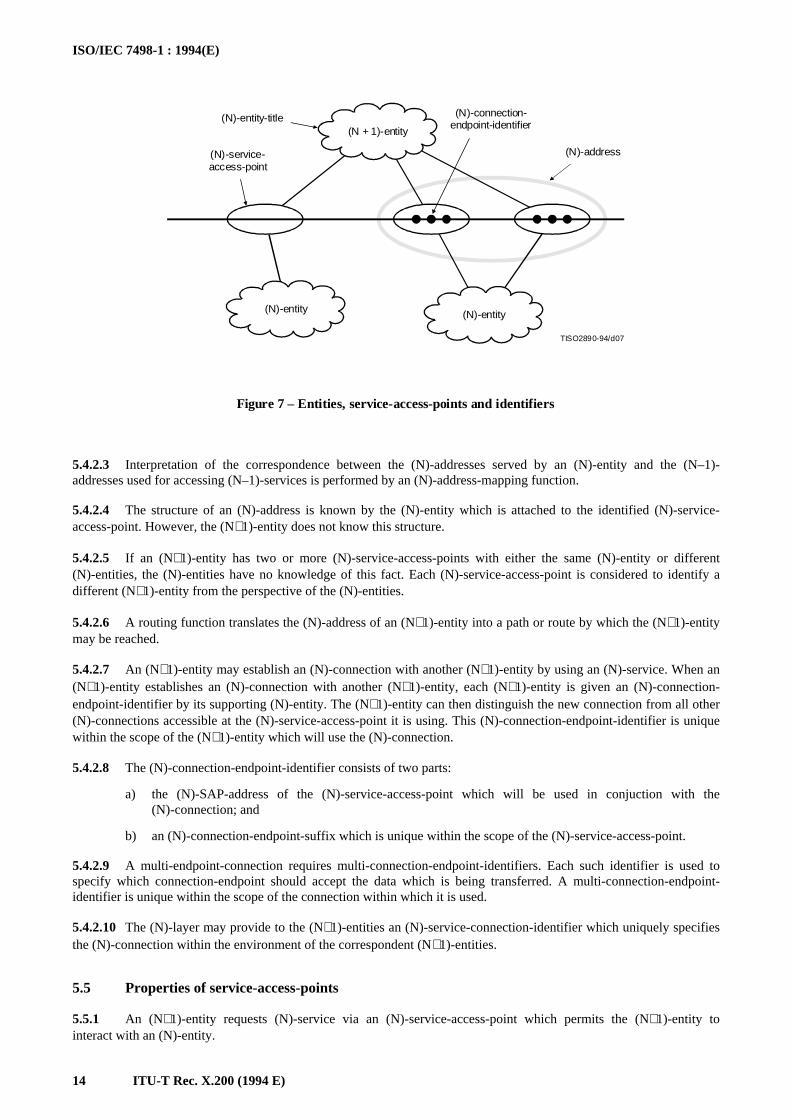
5.4.2.1 An (N)-service-access-point-address identifies a particular (N)-service-access-point to which an (N+1)-entityis attached (see Figure 7). When the (N+1)-entity is detached from the (N)-service-access-point, the (N)-SAP-address nolonger provides access to the (N+1)-entity. If the (N)-service-access-point is reattached to a different (N+1)-entity, thenthe (N)-SAP-address identifies the new (N+1)-entity and not the old one.
5.4.2.2 The use of an (N)-SAP-address to identify an (N+1)-entity is the most efficient mechanism if the permanenceof attachment between the (N+1)-entity and the (N)-service-access-point can be assured.
ISO/IEC 7498-1 : 1994(E)
14 ITU-T Rec. X.200 (1994 E)
TISO2890-94/d07
(N + 1)-entity
(N)-entity (N)-entity
(N)-connection-endpoint-identifier
(N)-address(N)-service-access-point
(N)-entity-title
Figure 7 – Entities, service-access-points and identifiers
FIGURE 7/X.200...[D07] = 8.5 CM
5.4.2.3 Interpretation of the correspondence between the (N)-addresses served by an (N)-entity and the (N–1)-addresses used for accessing (N–1)-services is performed by an (N)-address-mapping function.
5.4.2.4 The structure of an (N)-address is known by the (N)-entity which is attached to the identified (N)-service-access-point. However, the (N+1)-entity does not know this structure.
5.4.2.5 If an (N+1)-entity has two or more (N)-service-access-points with either the same (N)-entity or different(N)-entities, the (N)-entities have no knowledge of this fact. Each (N)-service-access-point is considered to identify adifferent (N+1)-entity from the perspective of the (N)-entities.
5.4.2.6 A routing function translates the (N)-address of an (N+1)-entity into a path or route by which the (N+1)-entitymay be reached.
5.4.2.7 An (N+1)-entity may establish an (N)-connection with another (N+1)-entity by using an (N)-service. When an(N+1)-entity establishes an (N)-connection with another (N+1)-entity, each (N+1)-entity is given an (N)-connection-endpoint-identifier by its supporting (N)-entity. The (N+1)-entity can then distinguish the new connection from all other(N)-connections accessible at the (N)-service-access-point it is using. This (N)-connection-endpoint-identifier is uniquewithin the scope of the (N+1)-entity which will use the (N)-connection.
5.4.2.8 The (N)-connection-endpoint-identifier consists of two parts:
a) the (N)-SAP-address of the (N)-service-access-point which will be used in conjuction with the(N)-connection; and
b) an (N)-connection-endpoint-suffix which is unique within the scope of the (N)-service-access-point.
5.4.2.9 A multi-endpoint-connection requires multi-connection-endpoint-identifiers. Each such identifier is used tospecify which connection-endpoint should accept the data which is being transferred. A multi-connection-endpoint-identifier is unique within the scope of the connection within which it is used.
5.4.2.10 The (N)-layer may provide to the (N+1)-entities an (N)-service-connection-identifier which uniquely specifiesthe (N)-connection within the environment of the correspondent (N+1)-entities.
5.5 Properties of service-access-points
5.5.1 An (N+1)-entity requests (N)-service via an (N)-service-access-point which permits the (N+1)-entity tointeract with an (N)-entity.
ISO/IEC 7498-1 : 1994(E)
ITU-T Rec. X.200 (1994 E) 15
5.5.2 Both the (N)- and (N+1)-entities attached to an (N)-service-access-point are in the same system.
5.5.3 An (N+1)-entity may concurrently be attached to one or more (N)-service-access-points attached to the sameor different (N)-entities.
5.5.4 An (N)-entity may concurrently be attached to one or more (N+1)-entities through (N)-service-access-points.
5.5.5 An (N)-service-access-point is attached to only one (N)-entity and to only one (N+1)-entity at a time.
5.5.6 An (N)-service-access-point may be detached from an (N+1)-entity and reattached to the same or another(N+1)-entity.
5.5.7 An (N)-service-access-point may be detached from an (N)-entity and reattached to the same or another(N)-entity.
5.5.8 An (N)-service-access-point is located by means of its (N)-SAP-address. An (N)-SAP-address is used by an(N+1)-entity to request an instance of communication.
5.5.9 An (N)-service-access-point may support:
a) (N)-connection-mode service only;
b) (N)-connectionless-mode service only;
c) (N)-connection-mode services and (N)-connectionless-mode services concurrently.
5.5.10 A single (N+1)-entity may concurrently be using several (N)-connections and an (N)-connectionless-modeservice through one or more (N)-service-access-points to which it is attached.
5.5.11 (N+1)-entities distinguish between instances of the (N)-connectionless-mode services and the (N)-connection-mode services offered concurrently through the same (N)-service-access-point by the uniqueness of the interactionsprescribed for these services.
5.6 Data-units
5.6.1 Definitions
5.6.1.1 (N)-protocol-control information: Information exchanged between (N)-entities to co-ordinate their jointoperation.
5.6.1.2 (N)-user-data: The data transferred between (N)-entities on behalf of the (N+1)-entities for whom the(N)-entities are providing services.
5.6.1.3 (N)-protocol-data-unit: A unit of data specified in an (N)-protocol and consisting of (N)-protocol-control-information and possibly (N)-user-data.
5.6.1.4 (N)-service-data-unit: An amount of information whose identity is preserved when transferred betweenpeer-(N+1)-entities and which is not interpreted by the supporting (N)-entities.
5.6.1.5 expedited (N)-service-data-unit. (N)-expedited-data-unit: A small (N)-service-data-unit whose transfer isexpedited. The (N)-layer ensures that an expedited-data-unit will not be delivered after any subsequent service-data-unitor expedited unit sent on that connection.
5.6.2 Description
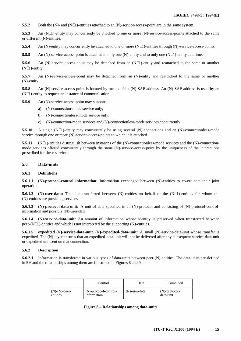
5.6.2.1 Information is transferred in various types of data-units between peer-(N)-entities. The data-units are definedin 5.6 and the relationships among them are illustrated in Figures 8 and 9.
Figure 8 – Relationships among data-units
Control Data Combined
(N)-(N)-peer-entities
(N)-protocol-control-information
(N)-user-data (N)-protocol-data-unit
ISO/IEC 7498-1 : 1994(E)
16 ITU-T Rec. X.200 (1994 E)
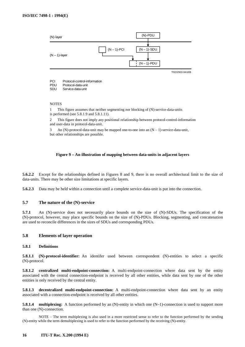
TISO2900-94/d08
(N)-PDU
(N – 1)-SDU
(N – 1)-PDU
(N – 1)-PCI
(N)-layer
(N – 1)-layer
PCIPDUSDU
Protocol-control-informationProtocol-data-unitService-data-unit
NOTES
1 This figure assumes that neither segmenting nor blocking of (N)-service-data-unitsis performed (see 5.8.1.9 and 5.8.1.11).
2 This figure does not imply any positional relationship between protocol-control-informationand user-data in protocol-data-unit.
3 An (N)-protocol-data-unit may be mapped one-to-one into an (N – 1)-service-data-unit,but other relationships are possible.
Figure 9 – An illustration of mapping between data-units in adjacent layers
FIGURE 9/X.200...[D08] = 11 CM
5.6.2.2 Except for the relationships defined in Figures 8 and 9, there is no overall architectural limit to the size ofdata-units. There may be other size limitations at specific layers.
5.6.2.3 Data may be held within a connection until a complete service-data-unit is put into the connection.
5.7 The nature of the (N)-service
5.7.1 An (N)-service does not necessarily place bounds on the size of (N)-SDUs. The specification of the(N)-protocol, however, may place specific bounds on the size of (N)-PDUs. Blocking, segmenting, and concatenationare used to reconcile differences in the sizes of SDUs and corresponding PDUs.
5.8 Elements of layer operation
5.8.1 Definitions
5.8.1.1 (N)-protocol-identifier: An identifer used between correspondent (N)-entities to select a specific(N)-protocol.
5.8.1.2 centralized multi-endpoint-connection: A multi-endpoint-connection where data sent by the entityassociated with the central connection-endpoint is received by all other entities, while data sent by one of the otherentities is only received by the central entity.
5.8.1.3 decentralized multi-endpoint-connection: A multi-endpoint-connection where data sent by an entityassociated with a connection-endpoint is received by all other entities.
5.8.1.4 multiplexing: A function performed by an (N)-entity in which one (N–1)-connection is used to support morethan one (N)-connection.
NOTE – The term multiplexing is also used in a more restricted sense to refer to the function performed by the sending(N)-entity while the term demultiplexing is used to refer to the function performed by the receiving (N)-entity.
ISO/IEC 7498-1 : 1994(E)
ITU-T Rec. X.200 (1994 E) 17
5.8.1.5 demultiplexing: A function performed by an (N)-entity which identifies (N)-protocol-data-units for morethan one (N)-connection within an (N–1)-connection. It is the reverse function of the multiplexing function performedby the (N)-entity sending the (N–1)-service-data-units.
5.8.1.6 splitting: A function within the (N)-layer by which more than one (N–1)-connection is used to support one(N)-connection.
NOTE – The term splitting is also used in a more restrictive sense to refer to the function performed by the sending(N)-entity while the term recombining is used to refer to the function performed by the receiving (N)-entity.
5.8.1.7 recombining: The function performed by an (N)-entity which identifies (N)-protocol-data-units for a single(N)-connection in (N–1)-service-data-units received on more than one (N–1)-connection. It is the reverse function of thesplitting function performed by the (N)-entity sending the (N–1)-service-data-units.
5.8.1.8 flow control: A function which controls the flow of data within a layer or between adjacent layers.
5.8.1.9 segmenting: A function performed by an (N)-entity to map one (N)-service-data-unit into multiple(N)-protocol-data-units.
5.8.1.10 reassembling: A function performed by an (N)-entity to map multiple (N)-protocol-data-units into one(N)-service-data-unit. It is the reverse function of segmenting.
5.8.1.11 blocking: A function performed by an (N)-entity to map multiple (N)-service-data-units into one(N)-protocol-data-unit.
5.8.1.12 deblocking: A function performed by an (N)-entity to identify multiple (N)-service-data-units which arecontained in one (N)-protocol-data-unit. It is the reverse function of blocking.
5.8.1.13 concatenation: A function performed by an (N)-entity to map multiple (N)-protocol-data-units into one (N–1)-service-data-unit.
NOTE – Blocking and concatenation though similar (they both permit grouping of data-units) may serve differentpurposes. For instance, concatenation permits the (N)-layer to group one or several acknowledgement (N)-PDUs with one (or several)(N)-PDUs containing user-data. This would not be possible with the blocking function only. Note also that the two functions may becombined so that the (N)-layer performs blocking and concatenation.
5.8.1.14 separation: A function performed by an (N)-entity to identify multiple (N)-protocol-data-units which arecontained in one (N–1)-service-data-unit. It is the reverse function of concatenation.
5.8.1.15 sequencing: A function performed by the (N)-layer to preserve the order of (N)-service-data-units that weresubmitted to the (N)-layer.
5.8.1.16 acknowledgement: A function of the (N)-layer which allows a receiving (N)-entity to inform a sending(N)-entity of the receipt of an (N)-protocol-data-unit.
5.8.1.17 reset: A function which sets the corresponding (N)-entities to a predefined state with a possible loss orduplication of data.
5.8.1.18 (N)-protocol-version-identifier: An identifier conveyed between correspondent (N)-entities which allows theselection of the version of an (N)-protocol.
NOTE – The definition of a new (N)-protocol-version-identifier presupposes a minimal common knowledge of the(N)-protocol identified by the preceding (N)-protocol-version-identifier. When such a minimal common knowledge cannot beachieved, the (N)-protocols are considered to be independent and different.
5.8.2 Protocol selection and identification
5.8.2.1 Protocol identification is the process of determining the type of protocol being used.
5.8.2.2 One or more (N)-protocols may be defined for the (N)-layer. An (N)-entity may employ one or more(N)-protocols.
5.8.2.3 Meaningful communication between (N)-entities requires the agreed selection of one (N)-protocol.
5.8.2.4 (N)-protocol-identifiers name the specific protocols defined. An (N+1)-protocol-identifier cannot be partof (N)-PCI. Thus, an (N)-service uses (N)-addresses to identify an (N+1)-protocol, as described in Rec. X.650 |ISO 7498-3.
5.8.2.5 Since not all protocols (either OSI or non-OSI) can be assumed to carry an (N)-protocol-identifier, an(N)-protocol-identifier cannot be used to distinguish OSI and non-OSI protocols. The proper mechanism to use in thesesituations is an (N)-address.
ISO/IEC 7498-1 : 1994(E)
18 ITU-T Rec. X.200 (1994 E)
5.8.3 Protocol version selection and identification
5.8.3.1 Protocol version identification
5.8.3.1.1 Protocol version identification is a mechanism to identify the level of a particular protocol being used. Theidentification of the protocol version presupposes that the protocol itself has been identified either implicitly or by use ofapproved mechanisms.
5.8.3.1.2 It may be convenient, in many cases, to recognize a sub-version id to be carried in (N)-PCI along with the(N)-protocol-version-id. This allows keeping track of minor evolutions of a given protocol version (e.g. in order todetermine the degree of integration of defect reports, etc.). The decision of whether or not to introduce such a sub-version id is of the responsibility of specific (N)-layer standards. However, only the (N)-protocol-version-id, regardlessof any additional subversion id, is taken into account in order to determine whether or not communication is possiblebetween peer-(N)-entities.
5.8.3.2 The need for a new protocol version
5.8.3.2.1 The need for a new protocol version arises from changes made in the protocol. These changes can be:
1) addition of new functions (i.e. not defined in the existing protocol specifications);
2) deletion of existing functions (i.e. which were defined in the existing protocol specifications);
3) modification of existing functions; or
4) substitution of an alternate way to provide existing functions.
5.8.3.2.2 Changes made in a protocol will not always imply the need for a new protocol version (or for a new protocol).A new protocol version (or new protocol) becomes necessary when these changes lead to a significant functionalmodification which cannot be compatibly negotiated using the existing protocol specifications so that a real open systemutilizing the newly specified protocol functions would not be able to communicate with a real open system utilizing theold specifications.
5.8.3.2.3 In such cases, if the two sets of protocol functions share at least a common understanding of the protocolversion identification mechanisms (e.g. conveying, encoding, negotiating protocol version identifiers), they areconsidered to be two different versions of the same protocol, otherwise they are considered to be two different protocols.
NOTES
1 It is important to note that significant functional modifications are not always coupled to changes to protocol elementsexchanged between pair entities (e.g. modification of the behavior of an (N)-entity due to the introduction of transparent services).
2 It should be noted that new protocol versions are not directly related to the administrative process of revising existingstandards. Such a process may or may not lead to a new protocol version depending on the degree of modification which has takenplace.
5.8.3.3 Negotiation mechanisms
5.8.3.3.1 The negotiation of protocol version can only occur in connection-mode communication. An (N)-protocol-version-id field should be present in PDUs relevant to connection establishment. A mechanism for handling protocolversion identification is to determine, by means of the (N)-protocol-version-id, which version should be invoked on aspecific connection between the calling and called (N)-entities.
5.8.3.3.2 A calling (N)-entity sends information of all supported versions to a called (N)-entity. The called (N)-entityexamines whether or not there are any supported versions common to the calling and called (N)-entities. If there is morethan one common version, the latest common version is selected. If there is no common version, the connectionestablishment request is refused.
5.8.3.3.3 The sub-version id, when present, is not used in the negotiation mechanisms.
5.8.3.3.4 In connectionless-mode protocols, no negotiation mechanism is provided. Identification of the protocol versionis either implicit (e.g. a priori knowledge) or explicitly conveyed in the PDUs.
5.8.4 Properties of connectionless-mode transmission
5.8.4.1 All the information required by an (N)-connectionless-mode service to deliver an (N)-service-data-unit(destination address, quality of service required, options, etc.) is presented to it with the (N)-service-data-unit in a singlelogical service access by the sending (N+1)-entity.
ISO/IEC 7498-1 : 1994(E)
ITU-T Rec. X.200 (1994 E) 19
5.8.4.2 All information related to an (N)-service-data-unit, together with the (N)-service-data-unit itself, is receivedfrom the (N)-service in a single logical service access by the receiving (N+1)-entity.
5.8.4.3 To provide the (N)-connectionless-mode service, the (N)-layer performs functions as described in 5.3.3.3.These functions are supported by (N)-protocols.
5.8.4.4 If an (N)-service-data-unit cannot be accepted by an (N+1)-entity at the time of its arrival at an (N)-service-access-point, the (N+1)-entity may apply service boundary flow control (see 5.8.8.4). This may result in the discardingof the (N)-service-data-unit by the (N)-service provider or, where flow control is provided, in the exercise of serviceboundary flow control at the sending (N)-service-access-point by the (N)-service provider .
5.8.4.5 An (N)-connectionless-mode service may allow the transmission of copies of an (N)-service-data-unit to anumber of destination (N)-service-access-points. (N)-service-data-units transmitted from a number of source(N)-service-access-points can be received at one destination (N)-service-access point. The (N)-layer does not assume anylogical relationship between these (N)-service-data-units.
5.8.4.6 No (N)-protocol-control-information is exchanged between (N)-entities concerning the mutual willingness ofthe (N+1)-entities to exchange data using an (N)-connectionless-mode service.
NOTES
1 The specific interface mechanism employed by a particular implementation of a connectionless-mode service mayinvolve more than one interface exchange to accomplish the single logical service access necessary to initiate a connectionless-modetransmission. However, this is a local implementation detail.
2 The transmission of each (N)-service-data-unit by an (N)-connectionless-mode service should be entirelyself-contained. All the addressing and other information required by the (N)-layer to deliver the (N)-service-data-unit to its destinationshould be included in the service access for each transmission.
3 It is a basic characteristic of connectionless-mode service that no negotiation of the parameters for a transmissiontakes place at the time the service is accessed and no dynamic association is set up between the parties involved. However,considerable freedom of choice can be preserved by allowing most parameter values and options (such as transfer rate, acceptableerror rate, etc.) to be specified at the time the service is accessed. In a given implementation, if the local (N)-subsystem determinesimmediately (from information available to it locally) that the requested transmission cannot be performed under the conditionsspecified, it may abort the transmission, returning an implementation specific error message. If the same determination is made later,after the service access has been completed, the transmission is abandoned, since the (N)-layer is assumed not to have the informationnecessary to take any other action.
5.8.5 Properties of connection-mode transmission
5.8.5.1 An (N)-connection is an association established for communication between two or more (N+1)-entities,identified by their (N)-addresses. An (N)-connection is offered as a service by the (N)-layer, so that information may beexchanged between the (N+1)-entities.
5.8.5.2 An (N+1)-entity may have, simultaneously, one or more (N)-connections with other (N+1)-entities, with anygiven (N+1)-entity, and with itself.
5.8.5.3 An (N)-connection is established by referencing, either explicitly or implicity, an (N)-address for the source(N+1)-entity and an (N)-address for each of one or more destination (N+1)-entities.
NOTE – The specific interface mechanism employed by a particular implementation of a connection-mode service mayinvolve more than one interface exchange to accomplish the single logical service access necessary to initiate a connection-modetransmission. However, this is a local implementation detail.
5.8.5.4 The source (N)-address and one or more of the destination (N)-addresses may be the same. One or more of thedestination (N)-addresses may be the same while the source (N)-address is different. All may be different.
5.8.5.5 One (N)-connection-endpoint is constructed for each (N)-SAP-address referenced explicitly or implicitly whenan (N)-connection is established.
5.8.5.6 An (N+1)-entity accesses an (N)-connection via an (N)-service-access-point.
5.8.5.7 An (N)-connection has two or more (N)-connection-endpoints.
5.8.5.8 An (N)-connection-endpoint is not shared by (N+1)-entities or (N)-connections.
5.8.5.9 An (N)-connection-endpoint relates three elements:
a) an (N+1)-entity;
b) an (N)-entity; and
c) an (N)-connection.
ISO/IEC 7498-1 : 1994(E)
20 ITU-T Rec. X.200 (1994 E)
5.8.5.10 The (N)-entity and the (N+1)-entity related by an (N)-connection-endpoint are those implied by the (N)-SAP-address referenced when the (N)-connection is established.
5.8.5.11 An (N)-connection-endpoint has an identifier, called an (N)-connection-endpoint-identifier, which is uniquewithin the scope of the (N+1)-entity which is bound to the (N)-connection-endpoint.
5.8.5.12 An (N)-connection-endpoint-identifier is not the same as an (N)-SAP-address.
5.8.5.13 An (N+1)-entity references an (N)-connection, using its (N)-connection-endpoint-identifier.
5.8.5.14 Multi-endpoint-connections are connections which have three or more connection-endpoints. Two types ofmulti-endpoint-connection are defined:3)
a) centralized; and
b) decentralized.
5.8.5.15 A centralized multi-endpoint-connection has a central connection-endpoint. Data sent by the entity associatedwith the central connection-endpoint is received by the entities associated with all other connection-endpoints. The datasent by an entity associated with any other connection-endpoint is received by the entity associated with the centralconnection-endpoint.
5.8.5.16 On a decentralized multi-endpoint-connection, data sent by an (N)-entity associated with any connection-endpoint is received by the (N)-entities associated with all of the other connection-endpoints.
5.8.6 Connection establishment and release
5.8.6.1 Introduction
5.8.6.1.1 All (N)-connections require establishment and release procedures. These procedures
– may be designed to send (N)-PCI on the same (N)-connection as (N)-user-data (sometimes calledin-band);
– may be designed to send (N)-PCI on a different (N)-connection than (N)-user-data (sometimes calledout-of-band); or
– may be a priori procedures.
A priori procedures are not the concern of OSI. These procedures may or may not be standardized. In all of these cases,the basic properties of the procedures are the same. Equivalent information is exchanged to initialize and synchronize thestate of the correspondent (N)-entities. OSI is only concerned with in-band and out-of-band establishment and releaseprocedures which are standardized.
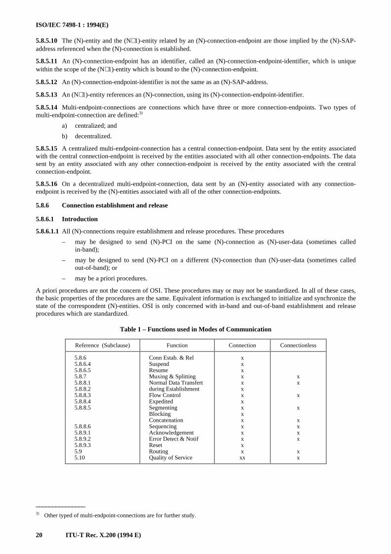
Table 1 – Functions used in Modes of Communication
_______________3) Other typed of multi-endpoint-connections are for further study.
Reference (Subclause) Function Connection Connectionless
5.8.65.8.6.45.8.6.55.8.75.8.8.15.8.8.25.8.8.35.8.8.45.8.8.5
5.8.8.65.8.9.15.8.9.25.8.9.35.95.10
Conn Estab. & RelSuspendResumeMuxing & SplittingNormal Data Transfertduring EstablishmentFlow ControlExpeditedSegmentingBlockingConcatenationSequencingAcknowledgementError Detect & NotifResetRoutingQuality of Service
xxxxxxxxxxxxxxxxxx
xx
x
x
xxxx
xx
ISO/IEC 7498-1 : 1994(E)
ITU-T Rec. X.200 (1994 E) 21
5.8.6.1.2 OSI protocols, operating independently of a given set of instances of communication, may be employed tocontrol the resources that are required to support those instances of communications. These protocols, which are oftencalled “out-of-band”, can be used, for example, in support of the establishment of (N)-connections. Information neededfor the establishment of an (N)-connection may be conveyed, not only through the direct (normally called “in-band”)(N)-protocol, but also as part of a different (N)-layer protocol, common to many instances of communications.
5.8.6.1.3 Non-standard procedures can be allowed in a compatible manner without affecting the operation of the(N)-protocol or (N+1)-protocol. These non-standard procedures should not affect addressing, quality of service, serviceprimitives, OSI management, etc.
5.8.6.1.4 Some (N)-protocols may provide for the combining of connection establishment and connection releaseprotocol exchanges.
5.8.6.2 Connection establishment
5.8.6.2.1 The establishment of an (N)-connection by peer-(N)-entities of an (N)-layer requires the following:
a) the availability of an (N–1)-service between the supporting (N)-entities; and
b) both (N)-entities be in a state in which they can execute the connection establishment protocol exchange.
5.8.6.2.2 If it is not already available, an (N–1)-service has to be established by peer-(N–1)-entities of the (N–1)-layer.This requires, for the (N–1)-layer, the same conditions as described above for the (N)-layer.
5.8.6.2.3 The same consideration applies downwards until either an available lower layer service or the physicalmedium for OSI is encountered.
5.8.6.2.4 Depending upon the characteristics of the (N–1)-service and of the establishment protocol exchange,the establishment of an (N)-connection may or may not be done in conjunction with the establishment of the (N–1-connection.
5.8.6.2.5 The characteristics of the (N)-service with regard to the establishment of the (N)-connection vary dependingupon whether or not (N)-user-data can be transferred by the connection establishment protocol exchange for eachdirection of the (N)-connection.
5.8.6.2.6 Where (N)-user-data is transferred by the (N)-connection establishment protocol exchange, the (N+1)-protocolmay take advantage of this to allow an (N+1)-connection to be established in conjunction with the establishment of the(N)-connection. This is termed “embedding of connection establishment”. If embedding at all layers were to bepermitted, then the length of the user-data parameter in a connection establishment PDU may have to be indefinite.
5.8.6.2.7 At certain layers the complexity involved in providing arbitrarily long user data fields in connectionestablishment primitives at every layer may outweigh any savings that could be accomplished by embedding.
5.8.6.2.8 Embedding between adjacent layers where there are multiplexing, re-use, or quality of service enhancementfunctions causes complexity and redundancy of mechanism. Such additional complexity and redundancy do notnecessarily cancel out all of the potential advantages of embedding. It is the responsibility of a layer to decide whenprotocol elements should be passed in the connection request or in the first data request, provided that adequateprotocols are defined which allow such a selection.
5.8.6.2.9 If embedding is used, failure of a connection establishment will result in failure of the embedded connectionestablishments.
5.8.6.3 Connection Release
5.8.6.3.1 The release of an (N)-connection is normally initiated by one of the (N+1)-entities associated in it.
5.8.6.3.2 The release of an (N)-connection may also be initiated by one of the (N)-entities supporting it as a result of anexception condition occurring in the (N)-layer or the layers below.
5.8.6.3.3 Depending upon the conditions, release of an (N)-connection may result in the discarding of (N)-user-data.
5.8.6.3.4 The orderly release of an (N)-connection requires either the availability of an (N–1)-connection, or a commonreference to time (for example, time of failure of the (N–1)-connection and common time-out). In addition, it requiresthat both (N)-entities are in a state in which they can execute the connection release protocol exchange. It is important tonote, however, that the release of an (N–1)-connection does not necessarily cause the release of the (N)-connection(s)which were using it; the (N–1)-connection can be re-established, or another (N–1)-connection substituted.
NOTE – The common reference to time refers to the expiration of time with respect to, or relative to an instance of service.
ISO/IEC 7498-1 : 1994(E)
22 ITU-T Rec. X.200 (1994 E)
5.8.6.3.5 The characteristics of the (N)-service with regard to the release of an (N)-connection can be of two kinds:
a) (N)-connections are either released immediately when the release protocol is initiated [(N)-user-data notyet delivered may be discarded]; or
b) release is delayed until all (N)-user-data sent previous to the initiation of the release protocol exchangehas been delivered (i.e. delivery confirmation has been received).
5.8.6.3.6 (N)-user-data may be transferred by the connection release protocol exchange.
5.8.6.4 The Suspend function
Suspend is an OSI function provided by the (N)-layer in which a (N–1)-connection can be terminated while the(N)-connection is preserved. A Suspend function in an (N)-layer may be invoked at the explicit request of an upper layerwhen an upper layer entity has knowledge of future activity that indicate that releasing the (N–1)-connection would beadvantageous, or it may be invoked spontaneously within the operation of the (N)-layer based on the occurrence of somecondition (e.g. some period of time with no data transferred) that makes it advantageous to release the (N–1)-connection.
5.8.6.5 The Resume function
Normal operation will be resumed as soon as one party or the other is required to communicate across the suspended (N–1)-connection. To resume such a connection, the (N)-layer will have to re-establish the (N–1)-connection.
5.8.7 Multiplexing and splitting
5.8.7.1 Within the (N)-layer, (N)-connections are mapped onto (N–1)-connections. The mapping may be one of threekinds:
a) one-to-one;
b) many (N)-connections to one (N–1)-connection (multiplexing); and
c) one (N)-connection to many (N–1)-connections (splitting).
5.8.7.2 Multiplexing may be needed in order to:
a) make more efficient or more economic use of the (N–1)-service; and
b) provide several (N)-connections in an environment where only a single (N–1)-connection exists.
5.8.7.3 Splitting may be needed in order to:
a) improve reliability where more than one (N–1)-connection is available;
b) provide the required grade of performance, through the utilization of multiple (N–1)-connections; and
c) obtain cost benefits by the utilization of multiple low cost (N–1)-connections each with less than therequired grade of performance.
5.8.7.4 Multiplexing and splitting each involve a number of associated functions which may not be needed forone-to-one connection mapping.
5.8.7.5 The functions associated with multiplexing are:
a) identification of the (N)-connection for each (N)-protocol-data-unit transferred over the (N–1)-connection, in order to ensure that (N)-user-data from the various multiplexed (N)-connections are notmixed. This identification is distinct from that of the (N)-connection-endpoint-identifiers and is called an(N)-protocol-connection-identifier;
b) flow control on each (N)-connection in order to share the capacity of the (N–1)-connection (see 5.8.8.3);and
c) scheduling the next (N)-connection to be serviced over the (N–1)-connection when more than one(N)-connection is prepared to send data.
5.8.7.6 The functions associated with splitting are:
a) scheduling the utilization of multiple (N–1)-connections used in splitting a single (N)-connection; and
b) resequencing of (N)-protocol-data-units associated with an (N)-connection since they may arrive out ofsequence even when each (N–1)-connection guarantees sequence of delivery (see 5.8.8.6).
ISO/IEC 7498-1 : 1994(E)
ITU-T Rec. X.200 (1994 E) 23
5.8.8 Transfer of data
5.8.8.1 Normal data transfer
5.8.8.1.1 Control information and user data are transferred between (N)-entities in (N)-protocol-data-units. An(N)-protocol-data-unit is a unit of data specified in an (N)-protocol and contains (N)-protocol-control-information andpossibly (N)-user-data.
5.8.8.1.2 (N)-protocol-control-information is transferred between (N)-entities using an (N–1)-service. (N)-protocol-control-information is any information that supports the joint operation of (N)-entities. (N)-user-data is passedtransparently between (N)-entities using an (N–1)-service.
5.8.8.1.3 An (N)-protocol-data-unit has a finite size, which may be limited by the (N–1)-protocol-data-unit size and bythe capabilities of the (N)-protocol. (N)-protocol-data-units are mapped into (N–1)-service-data-units. The interpretationof an (N)-protocol-data-unit is defined by the (N)-protocol in effect for the (N)-service.
5.8.8.1.4 An (N)-service-data-unit is transferred between an (N+1)-entity and an (N)-entity, through an (N)-service-access-point. Each (N)-service-data-unit is transferred as (N)-user-data in one or more (N)-protocol-data-units.
5.8.8.1.5 The exchange of data under the rules of an (N)-protocol can only occur if an instance of the (N–1)-serviceexists. If an instance of the (N–1)-service does not exist, it shall be established before an exchange of data can occur(see 5.8.6).
5.8.8.1.6 The quality of service agreed when the connection was established is related to the flow of service-data-unitsacross service-access-points.
5.8.8.1.7 Even when blocking takes place it is always within the quality of service agreed when the connection wasestablished. There is no case where data will be delayed indefinitely.
5.8.8.2 Data transfer during connection establishment and release
5.8.8.2.1 (N)-user-data may be transferred in the (N)-connection establishment protocol exchange and in the(N)-connection release protocol exchange.
5.8.8.2.2 The connection release protocol exchange may be combined with the connection establishment protocolexchange (see 5.8.6) to provide a means for the delivery of a single unit of (N)-user-data between correspondent(N+1)-entities with a confirmation of receipt.
5.8.8.3 Flow control
5.8.8.3.1 If flow control functions are provided in connectionless-mode, they can operate only on protocol-data-unitsand service-data-units.
5.8.8.3.2 Two types of flow control are identified:
a) peer flow control which regulates the rate at which (N)-protocol-data-units are sent between (N)-entitiessupporting either (N)-connectionless-mode or (N)-connection-mode transmission. Peer flow controlrequires protocol definitions and is based on protocol-data-unit size; and
b) service boundary flow control, which regulates the rate at which (N)-service-data-units are passedbetween an (N+1)-entity and an (N)-entity that supports either an (N)-connectionless-mode or(N)-connection-mode service. Service boundary flow control is based on (N)-service-data-unit size.
5.8.8.3.3 In connectionless-mode transmission, peer flow control may operate on (N)-PDUs within an (N)-SDU, but notacross (N)-SDU boundaries.
NOTE – It may happen however that peer flow control actually results in de facto action across (N)-SDU boundaries. Suchis the case when a sublayer using a connectionless-mode protocol operates over a sublayer operating a connection-mode protocol.Successive (N)-SDUs may be carried in connectionless PDUs which are themselves carried in the PDUs of the connection-modeprotocol. Any peer flow control operating on these PDUs thus results in an action across the (N)-SDU boundaries.
5.8.8.3.4 Multiplexing in a layer may require a peer flow control function for individual flows (see 5.8.7.5).
5.8.8.3.5 Peer flow control functions require flow control information to be included in the (N)-protocol-control-information of an (N)-protocol-data-unit.
5.8.8.3.6 If the size of service-data-units exceeds the maximum size of the (N)-user-data portion of an (N)-protocol-data-unit, then first segmentation shall be performed on the (N)-service-data-unit to make it fit within the (N)-protocol-data-units. Peer flow control can then be applied on the (N)-protocol-data-units.
ISO/IEC 7498-1 : 1994(E)
24 ITU-T Rec. X.200 (1994 E)
5.8.8.4 Expedited transfer of data
5.8.8.4.1 An expedited-data-unit is a service-data-unit which is transferred and/or processed with priority over normalservice-data-units. An expedited data transfer service may be used for signalling and interrupt purposes. Expedited datais only provided in connection-mode transmission.
5.8.8.4.2 Expedited data flow is independent of the states and operation of the normal data flow, although the data senton the two flows may be logically related. Conceptually, a connection that supports expedited flow can be viewed ashaving two subchannels, one for normal data, the other for expedited data. Data sent on the expedited channel isassumed to be given priority over normal data.
5.8.8.4.3 The transfer guarantees that an expedited-data-unit will not be delivered after any subsequent normal service-data-unit or expedited-data-unit sent on the connection.
5.8.8.4.4 Because the expedited flow is assumed to be used to transfer small amounts of data infrequently, simplifiedflow control mechanisms may be used on this data flow.
5.8.8.4.5 An expedited (N)-service-data-unit is intended to be processed by the receiving (N+1)-entity with priority overnormal (N)-service-data-units.
5.8.8.4.6 An expedited (N)-SDU is associated with a specific (N)-connection. Expedited data is defined relative to thenormal data flow of the associated (N)-connection. It is not necessarily expedited with respect to other (N)-connectionsor the connections in higher or lower layers. Expedited data at the (N)-layer will not necessarily be expedited at a lowerlayer.
5.8.8.4.7 Expedited data is not destructive and should not be confused with reset. The receiving entity may decide onsome response, such as to abort output, which is destructive, but that is a separate step. Further, expedited data is notprovided as a method for providing two streams of traffic at different priority levels. Expedited data is intended for usein exceptional circumstances; not as part of routine transfer of data.
5.8.8.4.8 Expedited data transmission as defined here does not occur with connectionless-mode data transmission.Although a similar effect may be achieved by requesting different quality of service parameters, such as lower delay timeor higher “priority”, it is impossible to guarantee delivery before “any subsequent normal SDU” by that means.
5.8.8.4.9 The constraints imposed by the above clauses are that the expedited-data-units:
1) have a limited size; and
2) are subject to separate flow control mechanisms in each (N)-layer.
5.8.8.4.10 In general, this latter constraint means that some small number of expedited data units (usually one) may beoutstanding at a time.
5.8.8.4.11 The consequence of these constraints is that, one should use caution in allowing for mapping an (N)-layerexpedited data service to an (N–1) layer expedited data service:
1) The size limitation can require dependency between layers to match sizes or might require segmentingand blocking of expedited (N)-SDUs at the (N–1) layer.
NOTE – If the sender provides for mapping of an expedited service through several layers, e.g. Application toSession Layers, and there are uniform size restrictions so that there is no segmenting, then the receiving station willoperate properly supporting the expedited service on a layer-by-layer basis whether or not it can provide the sameexpedited service mapping when it is the sender. Therefore, the size limitations may not have to be formally calledout in a standard.
2) There are likely to be problems in managing the use of the (N–1)-expedited-service if that service is usedby the (N)-layer in the operation of the (N)-protocol and in providing the (N)-expedited-service.
3) Such a mapping should not be done if the (N)-layer performs multiplexing onto (N–1)-connections. Flowcontrol on expedited at the (N–1) layer can interfere and inhibit expedited on the (N)-connectionsmultiplexed on the (N–1)-connection.
5.8.8.4.12 In consequence it is preferred that the expedited (N)-SDU be handled entirely by (N)-functions and onlyrely on the basic (N–1)-data transfer facility, not on special services of the (N–1)-layer, such as (N–1) expedited-service.Where the (N)-protocol makes no use of the (N–1)-expedited-service, an exception may occur. In this case, the(N)-expedited-service-data-unit may then be passed directly through to the (N–1)-expedited-service.
ISO/IEC 7498-1 : 1994(E)
ITU-T Rec. X.200 (1994 E) 25
5.8.8.4.13 Although it may be viable in certain very well constrained cases, as noted above, to map an expedited(N)-SDU to an expedited (N–1)-SDU, this mapping is to be avoided if possible. In some cases, layers may be required toprovide more elaborate expedited service such as secure expedited or more flexible flow control, etc. In these cases,more complicated mechanisms will be required to provide the services, such as a separate (N–1)-connection. Suchelaboration or mechanisms for efficiency lead to the recommendation to avoid the (N)-expedited to (N–1)-expeditedmapping.
5.8.8.4.14 It should be noted that the expedited service does not guarantee that lower layer flow control mechanismscan be bypassed. The expedited message may be permanently blocked.
5.8.8.5 Segmenting, blocking, and concatenation
5.8.8.5.1 Data-units in the various layers are not necessarily of compatible size. It may be necessary to performsegmenting, i.e. to map an (N)-service-data-unit into more than one (N)-protocol-data-unit. Similarly, separation mayoccur when (N)-protocol-data-units are mapped into a (N–1)-service-data-unit. Since it is necessary to preserve theidentity of (N)-service-data-units on an (N)-connection, functions shall be available to identify the segments of an(N)-service-data-unit and to allow the correspondent (N)-entities to reassemble the (N)-service-data-unit.
5.8.8.5.2 Segmenting may require that information be included in an (N)-protocol-control-information of an(N)-protocol-data-unit. Within a layer, (N)-protocol-control-information is added to the (N)-service-data-unit to form an(N)-protocol-data-unit when no segmenting or blocking is performed [see Figure 10 a)]. If segmenting is performed, an(N)-service-data-unit is mapped into several (N)-protocol-data-units with added (N)-protocol-control-information[see Figure 10 b)].
5.8.8.5.3 Conversely, it may be necessary to perform blocking. Blocking is the mechanism where several (N)-service-data-units with added (N)-protocol-control-information form an (N)-protocol-data-unit [see Figure 10 c)].
5.8.8.5.4 The Reference Model also permits concatenation where several (N)-protocol-data-units are concatenated into asingle (N–1)-service-data-unit [see Figure 10 d)].
5.8.8.5.5 Segmenting and concatenation functions may occur in connectionless-mode transmission. Blocking anddeblocking functions are not allowed in connectionless-mode transmission.
5.8.8.6 Sequencing
5.8.8.6.1 The (N–1)-services provided by the (N–1)-layer of the OSI architecture may not guarantee delivery of (N–1)-service-data-units in the same order as they were submitted by the (N)-layer. In such case, if the (N)-layer needs topreserve the order of (N–1)-service-data-units transferred through the (N–1)-layer sequencing mechanisms shall bepresent in the (N)-layer. Sequencing may require additional (N)-protocol-control-information.
5.8.8.6.2 In connectionless-mode transmission, sequencing occurs only indirectly when reassembly is applied to an(N)-SDU.
5.8.9 Error functions
5.8.9.1 Acknowledgement
5.8.9.1.1 An acknowledgement function may be used by (N)-entities using an (N)-protocol to obtain a higher probabilityof detecting protocol-data-unit loss than is provided by the (N–1)-layer. Each (N)-protocol-data-unit transferred betweencorrespondent (N)-entities is made uniquely identifiable, so that the receiver can inform the sender of the receipt of the(N)-protocol-data-unit. An acknowledgement function is also able to infer the non-receipt of (N)-protocol-data-units andthe need to take appropriate remedial action.
5.8.9.1.2 An acknowledgement function may require that information be included in the (N)-protocol-control-information of (N)-protocol-data-units.
5.8.9.1.3 The scheme for uniquely identifying (N)-protocol-data-units may also be used to support other functions suchas detection of duplicate data-units, segmenting and sequencing.
5.8.9.1.4 In connectionless-mode transmission, acknowledgement can only apply to (N)-PDUs, not on (N)-SDUs.
NOTE – Other forms of acknowledgement such as confirmation of delivery and confirmation of performance of an actionare for further study.
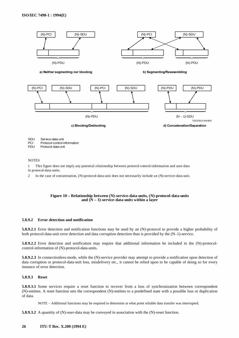
ISO/IEC 7498-1 : 1994(E)
26 ITU-T Rec. X.200 (1994 E)
TISO2910-94/d09
(N)-PCI (N)-SDU (N)-PCI (N)-SDU
(N)-PCI (N)-SDU (N)-PCI (N)-SDU (N)-PDU (N)-PDU
(N)-PDU (N)-PDU (N)-PDU
(N)-PDU (N – 1)-SDU
A�.EITHER�SEGMENTING�NOR�BLOCKING B�3EGMENTING�2EASSEMBLING
C�"LOCKING�$EBLOCKING D�#ONCATENATION�3EPARATION
SDUPCIPDU
Service-data-unitProtocol-control-informationProtocol-data-unit
NOTES
1 This figure does not imply any potential relationship between protocol-control-information and user-datain protocol-data-units.
2 In the case of concatenation, (N)-protocol-data-unit does not necessarily include an (N)-service-data-unit.
Figure 10 – Relationship between (N)-service-data-units, (N)-protocol-data-unitsand (N – 1)-service-data-units within a layer
FIGURE 10/X.200...[D09] = 15 CM
5.8.9.2 Error detection and notification
5.8.9.2.1 Error detection and notification functions may be used by an (N)-protocol to provide a higher probability ofboth protocol-data-unit error detection and data corruption detection than is provided by the (N–1)-service.
5.8.9.2.2 Error detection and notification may require that additional information be included in the (N)-protocol-control-information of (N)-protocol-data-units.
5.8.9.2.3 In connectionless-mode, while the (N)-service provider may attempt to provide a notification upon detection ofdata corruption or protocol-data-unit loss, misdelivery etc., it cannot be relied upon to be capable of doing so for everyinstance of error detection.
5.8.9.3 Reset
5.8.9.3.1 Some services require a reset function to recover from a loss of synchronization between correspondent(N)-entities. A reset function sets the correspondent (N)-entities to a predefined state with a possible loss or duplicationof data.
NOTE – Additional functions may be required to determine at what point reliable data transfer was interrupted.
5.8.9.3.2 A quantity of (N)-user-data may be conveyed in association with the (N)-reset function.
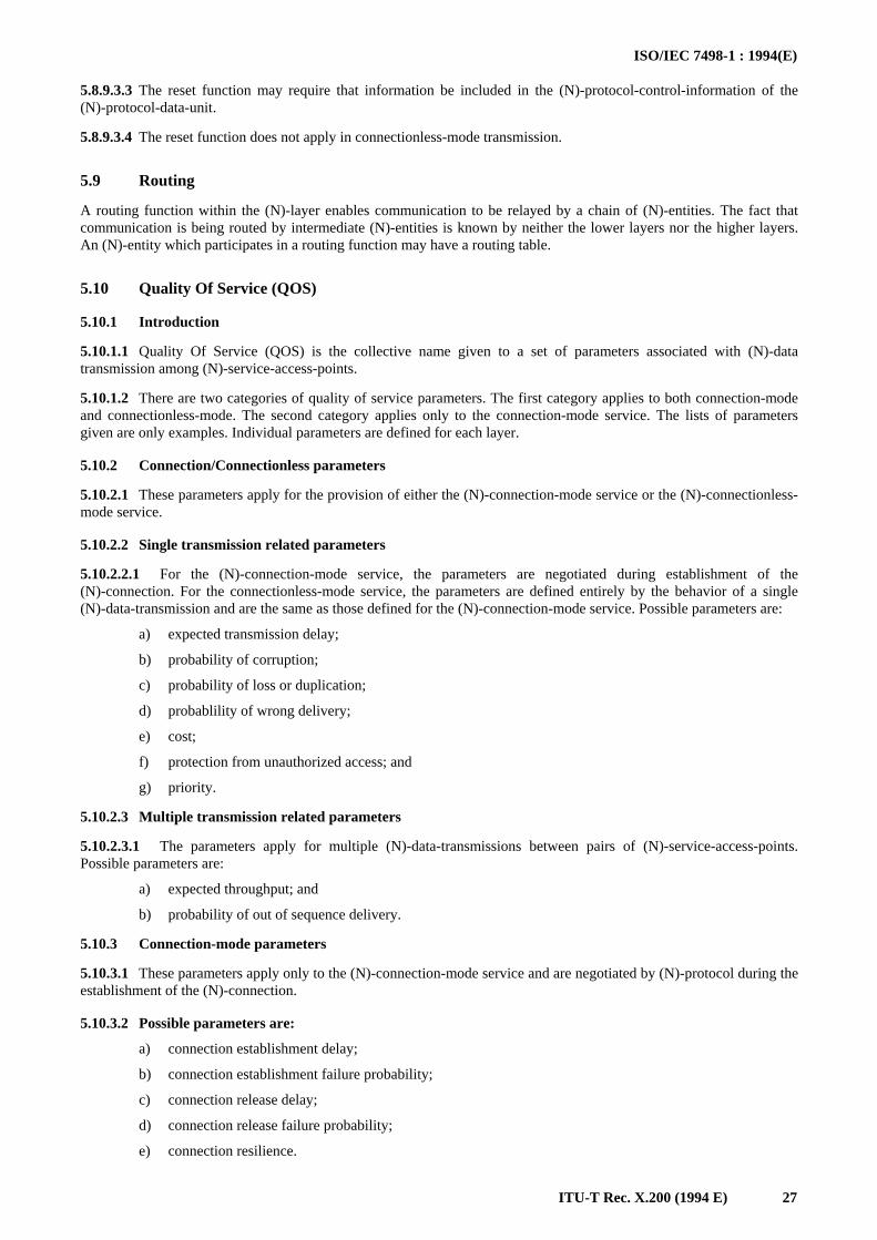
ISO/IEC 7498-1 : 1994(E)
ITU-T Rec. X.200 (1994 E) 27
5.8.9.3.3 The reset function may require that information be included in the (N)-protocol-control-information of the(N)-protocol-data-unit.
5.8.9.3.4 The reset function does not apply in connectionless-mode transmission.
5.9 Routing
A routing function within the (N)-layer enables communication to be relayed by a chain of (N)-entities. The fact thatcommunication is being routed by intermediate (N)-entities is known by neither the lower layers nor the higher layers.An (N)-entity which participates in a routing function may have a routing table.
5.10 Quality Of Service (QOS)
5.10.1 Introduction
5.10.1.1 Quality Of Service (QOS) is the collective name given to a set of parameters associated with (N)-datatransmission among (N)-service-access-points.
5.10.1.2 There are two categories of quality of service parameters. The first category applies to both connection-modeand connectionless-mode. The second category applies only to the connection-mode service. The lists of parametersgiven are only examples. Individual parameters are defined for each layer.
5.10.2 Connection/Connectionless parameters
5.10.2.1 These parameters apply for the provision of either the (N)-connection-mode service or the (N)-connectionless-mode service.
5.10.2.2 Single transmission related parameters
5.10.2.2.1 For the (N)-connection-mode service, the parameters are negotiated during establishment of the(N)-connection. For the connectionless-mode service, the parameters are defined entirely by the behavior of a single(N)-data-transmission and are the same as those defined for the (N)-connection-mode service. Possible parameters are:
a) expected transmission delay;
b) probability of corruption;
c) probability of loss or duplication;
d) probablility of wrong delivery;
e) cost;
f) protection from unauthorized access; and
g) priority.
5.10.2.3 Multiple transmission related parameters
5.10.2.3.1 The parameters apply for multiple (N)-data-transmissions between pairs of (N)-service-access-points.Possible parameters are:
a) expected throughput; and
b) probability of out of sequence delivery.
5.10.3 Connection-mode parameters
5.10.3.1 These parameters apply only to the (N)-connection-mode service and are negotiated by (N)-protocol during theestablishment of the (N)-connection.
5.10.3.2 Possible parameters are:
a) connection establishment delay;
b) connection establishment failure probability;
c) connection release delay;
d) connection release failure probability;
e) connection resilience.
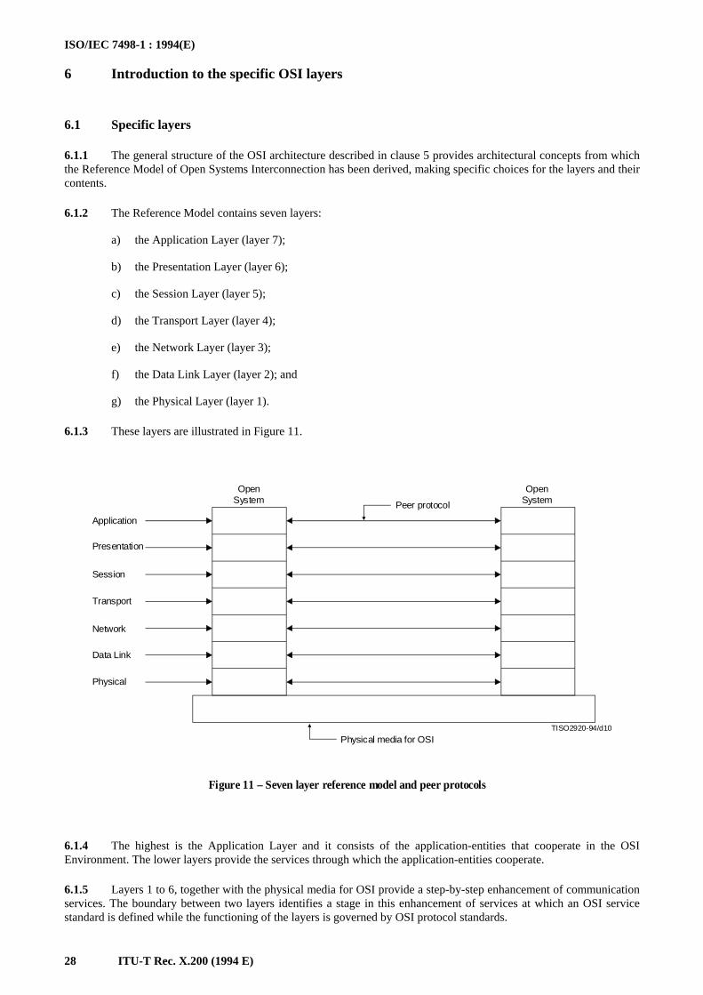
ISO/IEC 7498-1 : 1994(E)
28 ITU-T Rec. X.200 (1994 E)
6 Introduction to the specific OSI layersISO/IEC 7498-1 : 1994(E)
ITU-T Rec. X.200 (1994 E)
6.1 Specific layers
6.1.1 The general structure of the OSI architecture described in clause 5 provides architectural concepts from whichthe Reference Model of Open Systems Interconnection has been derived, making specific choices for the layers and theircontents.
6.1.2 The Reference Model contains seven layers:
a) the Application Layer (layer 7);
b) the Presentation Layer (layer 6);
c) the Session Layer (layer 5);
d) the Transport Layer (layer 4);
e) the Network Layer (layer 3);
f) the Data Link Layer (layer 2); and
g) the Physical Layer (layer 1).
6.1.3 These layers are illustrated in Figure 11.
TISO2920-94/d10
Application
Presentation
Session
Transport
Network
Data Link
Physical
OpenSystem Peer protocol
OpenSystem
Physical media for OSI
Figure 11 – Seven layer reference model and peer protocols
FIGURE 11/X.200...[D10] = 9.5 CM
6.1.4 The highest is the Application Layer and it consists of the application-entities that cooperate in the OSIEnvironment. The lower layers provide the services through which the application-entities cooperate.
6.1.5 Layers 1 to 6, together with the physical media for OSI provide a step-by-step enhancement of communicationservices. The boundary between two layers identifies a stage in this enhancement of services at which an OSI servicestandard is defined while the functioning of the layers is governed by OSI protocol standards.
ISO/IEC 7498-1 : 1994(E)
ITU-T Rec. X.200 (1994 E) 29
6.1.6 Not all open systems provide the initial source or final destination of data. When the physical media for OSIdo not link all open systems directly, some open systems act only as relay open systems, passing data to other opensystems. The functions and protocols which support the forwarding of data are then provided in the lower layers. This isillustrated in Figure 12.
TISO2930-94/d11
Application
Presentation
Session
Transport
Network
Data Link
Physical
OpenSystem
OpenSystemRelay open system
Physical media for OSI
Figure 12 – Communication involving relay open systems
FIGURE 12/X.200...[D11] = 9.5 CM
6.2 The principles used to determine the seven layers in the Reference Model
6.2.1 The following principles have been used to determine the seven layers in the Reference Model and are felt tobe useful for guiding further decisions in the development of OSI standards:
NOTE – It may be difficult to prove that any particular layering selected is the best possible solution. However, there aregeneral principles which can be applied to the question of where a boundary should be placed and how many boundaries should beplaced.
a) Do not create so many layers as to make the system engineering task of describing and integrating thelayers more difficult than necessary.
b) Create a boundary at a point where the description of services can be small and the number of interactionsacross the boundary are minimized.
c) Create separate layers to handle functions that are manifestly different in the process performed or thetechnology involved.
d) Collect similar functions into the same layer.
e) Select boundaries at a point which past experience has demonstrated to be successful.
f) Create a layer of easily localized functions so that the layer could be totally redesigned and its protocolschanged in a major way to take advantage of new advances in architectural, hardware or softwaretechnology without changing the services expected from and provided to the adjacent layers.
g) Create a boundary where it may be useful at some point in time to have the corresponding interfacestandardized.
ISO/IEC 7498-1 : 1994(E)
30 ITU-T Rec. X.200 (1994 E)
NOTES
1 Advantages and drawbacks of standardizing internal interfaces within open systems are not considered inthis Recommendation | International Standard. In particular, mention of, or reference to principle g), should not betaken to imply usefulness of standards for such internal interfaces.
2 It is important to note that OSI per se does not require interfaces within open systems to be standardized.Moreover, whenever standards for such interfaces are defined, adherence to such internal interface standards can inno way be considered as a condition of openness.
h) Create a layer where there is a need for a different level of abstraction in the handling of data, for examplemorphology, syntax, semantics.
j) Allow changes of functions or protocols to be made within a layer without affecting other layers; and
k) create for each layer, boundaries with its upper and lower layer only.
Similar principles have been applied to sublayering:
m) Create further subgrouping and organization of functions to form sublayers within a layer in cases wheredistinct communication services need it.
n) Create, where needed, two or more sublayers with a common, and therefore minimal functionality toallow interface operation with adjacent layers; and
p) allow by-passing of sublayers.
6.3 Layer descriptions
6.3.1 For each of the seven layers identified above, clause 7 provides:
a) an outline of the purpose of the layer;
b) a description of the services offered by the layer to the layer above; and
c) a description of the functions provided in the layer and the use made of the services provided by the layerbelow.
The descriptions, by themselves, do not provide a complete definition of the services and protocols for each layer. Theseare the subject of separate standards.
6.3.2 The facilities and functions listed in clause 7 for each layer represent the set of architectural possibilities. Aservice definition derived from these definitions for a particular layer may include some, or all of the facilities and it maybe characterized by none, some or all of the QoS parameters defined for the layer in clause 7 and in 5.10. A protocolspecification derived from these definitions for a particular layer may invoke some or all of the functions defined for thelayer. Such a service or protocol is constrained to not utilize nor invoke facilities or functions that are not listed.
6.4 Combinations of connection-mode and connectionless-mode
6.4.1 The provision of connectionless-mode and connection-mode services in specific layers of the Reference Modeland the characteristics of these services, together with the provision of functions providing for conversion within a layerbetween one mode of service and another, should be such as to ensure that it is possible to determine whether or notinterworking between open systems is possible. In order to maximize the possibility of interworking and to limit protocolcomplexity, there is a restriction on the number of layers within which conversion between one mode of service and theother may take place. This restriction applies to the layers as follows:
a) Special considerations apply to the Physical and Data Link Layers. Connection-mode and connectionless-mode services are not differentiated for the Physical Layer. The services of the Physical Layer aredetermined by the characteristics of the underlying medium and are too diverse to allow categorizationinto connection-mode and connectionless-mode operation. Functions in the Data Link Layer must convertbetween the services offered by the Physical Layer and the type of Data Link service needed.
b) Conversion may be provided in the Network Layer to support a network service of a given mode overa Data Link or subnetwork service of the other mode. This, in conjunction with relaying, provides anend-to-end network service of a given mode over concatenated subnetworks and/or Data Link services ofeither mode (see 5.3.4). Support of such conversions, where they are necessary to provide a given modeof network service, is a requirement of OSI standards.
ISO/IEC 7498-1 : 1994(E)
ITU-T Rec. X.200 (1994 E) 31
c) Conversion may be provided in the Transport Layer on condition that this makes use of only limitedadditional protocol functions over those required to support a given mode of transport service over thesame mode of network service. Since relaying is not permitted in the Transport Layer, such conversionscan only be applied between end-systems. Support for such conversions is not a requirement of OSIstandards.
d) Conversion in the Session and Presentation Layer is not permitted.
e) No conversion restrictions are imposed at the Application Layer.
NOTE – It is not possible (since a transport protocol operates between end-systems) for a transport protocol to provide thetransport service in an instance of communication between two end-systems utilizing (in that instance of communication) differentmodes of network service.
6.4.2 It follows from these restrictions that:
a) A real open system as defined in 4.1.2 shall support a given mode of transport service over a networkservice of the same mode (utilizing conversion within the Network Layer if necessary); such a systemmay, in addition, provide conversion in the Transport Layer.
b) A real system which only supports a given mode of transport service by providing conversion in theTransport Layer from a network service of the other mode is not fully open as defined in 4.1.2, since sucha system would be incapable of communicating with a system which only supports the given mode oftransport service over a network service of the same mode.
NOTE – The restriction that a given mode of transport service has to be supported by the same mode of network service isapplied so that systems may communicate without requiring prior agreement on the mode of network service to be used. Where prioragreement exists this restriction need not apply, although the requirements for systems to be fully open are as stated in item a) above.
6.5 Configurations of OSI Open Systems
6.5.1 Definitions
6.5.1.1 OSI End System: An open system, which for a particular instance of communication, is the ultimate sourceor destination of data.
6.5.1.2 OSI-(N)-Relay System: An open system which, for a particular instance of communication, makes use ofOSI functions up to and including functions of the (N)-layer and where a relay function is executed within the (N)-layer.
6.5.2 Properties
6.5.2.1 The Reference Model is not restricted to configurations in which only two real open systems participate in aninstance of communication nor to configurations in which all participating real open systems are connected to oneanother by the same physical medium. It also considers configurations in which communication between real opensystems involves other real open systems providing relay functions (see 5.3).
6.5.2.2 In order to distinguish between the roles of real open systems involved in an instance of communication, a realopen system in which there is an application-process acting either as final source or destination of data is termed an(OSI) end real open system for that instance of communication, and a real open system which is providing a relayfunction at layer N is termed an OSI (N)-relay system for that instance of communication.
6.5.2.3 From the point of view of a particular instance of communication a real open system may be acting in the roleeither of an OSI end system or an OSI (N)-relay system, but it does not necessarily act in the same way for all instancesof communication in which it is involved. These different views of the same open system may appear successively, oreven simultaneously when the open system is engaged in several communications with the same or different opensystems.
6.5.2.4 In configurations involving OSI-(N)-relay systems, the Reference Model considers the case where severalsubnetworks (see 7.5.1) are used in tandem or in parallel (see 7.5.2.3). This involves routing and relaying functions toestablish connections through such networks of OSI-(N)-relay systems. Such functions, which support the forwarding ofdata through OSI-(N)-relay systems, are provided in the lower three layers (see 6.1) or in the Application Layer.
6.5.2.5 In the context of distributed applications, relaying may be performed in application-entities.
6.5.2.6 Thus transport-entities are only involved in instances of communication where the open systems act as OSIend systems or as OSI-(N)-relay systems when the relaying function occurs in the Application Layer.
ISO/IEC 7498-1 : 1994(E)
32 ITU-T Rec. X.200 (1994 E)
7 Detailed description of the resulting OSI architecture
7.1 Application Layer
7.1.1 Definitions
7.1.1.1 application-entity: An active element, within an application process, embodying a set of capabilities which ispertinent to OSI and which is defined for the Application Layer, that corresponds to a specific application-entity-type(without any extra capabilities being used).
7.1.1.2 abstract syntax: The specification of Application-protocol-data-units by using notation rules which areindependent of the encoding technique used to represent them.
7.1.2 Purpose
7.1.2.1 As the highest layer in the Reference Model of Open Systems Interconnection, the Application Layer providesthe sole means for the application process to access the OSIE. Hence the Application Layer has no boundary with ahigher layer.
7.1.2.2 The aspects of an application process which need to be taken into account for the purpose of OSI arerepresented by one or more application-entities.
7.1.2.3 An application-entity represents one and only one application process in the OSIE. Different applicationprocesses may be represented by application-entities of the same application-entity-type. An application process may berepresented by a set of application-entitites: each application-entity in this set may be, but need not be, of differentapplication-entity-type.
7.1.3 Services provided by application-entities
7.1.3.1 General
7.1.3.1.1 Application-processes exchange information by means of application-entities which use application-protocolsand presentation services.
7.1.3.1.2 As the only layer in the Reference Model that directly provides services to the application-processes, theApplication Layer necessarily provides all OSI services directly usable by application-processes.
7.1.3.1.3 There exists no Application Layer service in the sense of (N)-layer service in that there is neither a generalservice provided to an upper layer nor a relation to a service-access-point.
NOTE – The related concept of OSI-service, defined in ISO/IEC 10731, is applicable in the Application Layer.
7.1.3.2 Connection-mode facilities
In addition to information transfer, such facilities may include, but are not limited to the following:
a) identification of the intended communication partners (for example by name, by address, by definitedescription, by generic description);
b) determination of the acceptable quality of service (for example response time, tolerable error rate, costvis-a-vis the previous considerations);
c) synchronization of cooperating applications;
d) agreement on responsibility for error recovery;
e) agreement on security aspects (e.g. authentication, access control, data integrity);
f) selection of mode of dialogue; and
g) identification of abstract syntaxes.
7.1.3.3 Connectionless-mode facilities
7.1.3.3.1 Where appropriate for connectionless-mode operation, equivalent facilities to those provided for connection-mode operation are provided in the Application Layer to application-processes.
ISO/IEC 7498-1 : 1994(E)
ITU-T Rec. X.200 (1994 E) 33
7.1.3.3.2 In addition to information transfer, such facilities constituting the service may include, but are not limited to,the following:
a) identification of intended communication partners;
b) establishment of authority to communicate;
c) authorization of intended communication partners;
d) determination of the acceptable quality of service; and
e) identification of abstract syntaxes.
7.1.4 Functions within the Application Layer
7.1.4.1 The Application Layer contains all those functions which imply communication in either mode between opensystems that are not already performed by the lower layers. These include functions performed by programs as well asfunctions performed by human beings.
7.1.4.2 In particular, application-entities maintain, as part of the pre-knowledge necessary in order to communicate,(or have access to, via use of a directory facility) information on the use of connection-mode and/or connectionless-mode transmission by the peer entities with which they may need to communicate.
7.1.4.3 Groupings of functions in the Application Layer
An application-entity can be structured internally into Application Layer objects representing groups of functions. Use ofone grouping of functions may depend on use of some other functions, and the active functions may vary during thelifetime of the application-association.
7.2 Presentation Layer
7.2.1 Definitions
7.2.1.1 concrete syntax: Those aspects of the rules used in the formal specification of data which embody a specificrepresentation of that data.
7.2.1.2 transfer syntax: The abstract and concrete syntax used in the transfer of data between open systems.
7.2.1.3 presentation context: An association of an abstract syntax with a transfer syntax.
7.2.2 Purpose
7.2.2.1 The Presentation Layer provides for the representation of information that application-entities eithercommunicate or refer to in their communication.
7.2.2.2 The Presentation Layer provides for common representation of the data transferred between application-entities. This relieves application-entities of any concern with the problem of “common” representation of information,i.e. it provides them with syntax independence.
7.2.2.3 The Presentation Layer ensures that the information content of the Application Layer data is preserved duringtransfer. Cooperating application-entities are responsible for determining the set of abstract syntaxes they employ in theircommunication. The Presentation Layer is informed of the abstract syntaxes that are to be employed. Knowing the set ofabstract syntaxes to be used by the application-entities, the Presentation Layer is responsible for selecting mutuallyacceptable transfer syntaxes.
NOTE – Presentation-entities have no role in determining the set of abstract syntaxes to be used by the application-entities.
7.2.3 Services provided to the Application Layer
7.2.3.1 The Presentation Layer provides the following facilities:
a) identification of a set of transfer syntaxes;
b) selection of transfer syntax; and
c) access to session services.
7.2.3.2 Identification of a set of transfer syntaxes provides one or more means of representing an abstract syntax.Selection of transfer syntax provides the means of initially selecting a transfer syntax and subsequently modifying theselection.
ISO/IEC 7498-1 : 1994(E)
34 ITU-T Rec. X.200 (1994 E)
7.2.3.3 Session services are provided to application-entities in the form of presentation services.
7.2.3.4 In connectionless-mode, segmentation and resassembly are not provided in the Presentation Layer. Thus, thesize of presentation-service-data-units is limited by the size of presentation-protocol-data-units and presentation-protocol-control-information.
7.2.4 Functions within the Presentation Layer
The Presentation Layer performs the following functions to help accomplish the presentation-services:
a) negotiation and re-negotiation of transfer syntax;
b) representation of the abstract syntax chosen by the application-entities in the transfer syntax negotiated orrenegotiated, including format and special purpose transformations (for example, data compression);
c) restoration of previously negotiated syntaxes on the occurrence of certain events; and
d) use of session-services.
7.2.4.1 Representation of abstract syntax
7.2.4.1.1 Application-entities agree on the abstract syntaxes that will be used for their communication. It is necessarythat these abstract syntaxes are represented in appropriate transfer syntaxes for communication to take place.
NOTE – Within a real open system, data defined in terms of an abstract syntax will be represented within the local systemenvironment by a local concrete syntax. A transformation may be necessary between the local concrete syntax and the transfer syntax.Thus, in communication between real open systems there are three concrete syntax versions of the data: the concrete syntax used bythe originating application-entity, the concrete syntax used by the receiving application-entity, and the concrete syntax used betweenthe presentation-entities (the transfer syntax). It is clearly possible that any or all of these syntaxes be identical. The local concretesyntaxes are not visible within the OSIE.
7.2.4.1.2 The fact that there is or is no actual transformation of concrete syntax has no impact on the presentation-protocol.
7.2.4.1.3 There is not a single predetermined transfer syntax for all OSI. In connection-mode, the transfer syntax to beused on a presentation-connection is negotiated between the correspondent presentation-entities.
7.2.4.1.4 In connectionless-mode, the transfer syntax is selected, but cannot be negotiated.
7.2.4.2 Negotiation of transfer syntax
7.2.4.2.1 Negotiation (or selection) of transfer syntax takes place between two presentation-entities when an application-entity provides the name of an abstract syntax for which a transfer syntax is required.
7.2.4.2.2 In general, there may be more than one combination of abstract syntax and transfer syntax. It may be possibleto represent a specific abstract syntax by one or more transfer syntaxes; also it may be possible to use one transfer syntaxto represent more than one abstract syntax. Each combination of abstract syntax and transfer syntax is called apresentation context. From the viewpoint of the application-entity, a presentation context represents a specific distinctuse of an abstract syntax.
7.2.4.3 Addressing and Multiplexing
There is no multiplexing or splitting in the Presentation Layer.
7.3 Session Layer
7.3.1 Definitions
7.3.1.1 token management: A facility of the session-service which allows correspondent presentation-entities tocontrol explicitly whose right it is to exercise certain session-services.
7.3.1.2 duplex mode: A mode of interaction where both presentation-entities may concurrently send and receivenormal data.
7.3.1.3 half-duplex mode: A mode of interaction where, at a given instance, only one of the two correspondentpresentation-entities is allowed to send normal data.
ISO/IEC 7498-1 : 1994(E)
ITU-T Rec. X.200 (1994 E) 35
7.3.1.4 session-connection synchronization: A facility of the session-service which allows presentation-entities todefine and to identify synchronization points and to reset a session-connection to a predefined state and to agree on aresynchronization point.
7.3.2 Purpose
7.3.2.1 The purpose of the Session Layer is to provide the means necessary for cooperating presentation-entities toorganize and to synchronize their dialogue and to manage their data exchange. To do this, the Session Layer providesservices to establish a session-connection between two presentation-entities, to support orderly data exchangeinteractions, and to release the connection in an orderly manner.
7.3.2.2 The only function of the Session Layer for connectionless-mode communication is to provide a mapping oftransport-addresses to session-addresses.
7.3.2.3 A session-connection is created when requested by a presentation-entity at a session-service-access-point. Thesession-connection exists until it is released by either the presentation-entities or the session-entities.
7.3.2.4 The initiating presentation-entity designates the destination presentation-entity by a session address. In general,there is a many-to-one correspondence between the session-addresses and transport-addresses. This does not implymultiplexing of session-connections onto transport-connections, but does imply that at session-connection establishmenttime, more than one presentation-entity is a potential target of a session-connection establishment request arriving on agiven transport-connection. However, when needed, there may be a one-to-one correspondence between the session-address and the transport-address.
7.3.3 Services provided to the Presentation Layer
7.3.3.1 General
7.3.3.1.1 In connection-mode, the services provided by the Session Layer are described below:
a) session-connection establishment;
b) session-connection release;
c) normal data transfer;
d) expedited data transfer;
e) token management;
f) session-connection synchronization;
g) exception reporting;
h) activity management;
j) typed data transfer; and
k) resynchronization.
7.3.3.1.2 In connectionless-mode, the Session Layer provides the following services:
a) connectionless-mode transmission using the transport-connectionless-mode service; and
b) exception reporting.
7.3.3.1.3 In connectionless-mode, segmentation and resassembly are not provided in the Session Layer. Thus, the size ofsession-service-data-units is limited by the size of session-protocol-data-units and session-protocol-control-information.
7.3.3.2 Session-connection establishment
7.3.3.2.1 The session-connection establishment service enables two presentation-entities to establish a session-connection between them. The presentation-entities are identified by session-addresses used to request the establishmentof the session-connection.
7.3.3.2.2 The session-connection establishment service allows the presentation-entities to determine cooperatively theunique values of session-connection parameters at the time the session-connection is established.
7.3.3.2.3 The session-connection establishment service provides a session-connection identification parameter whichallows the presentation-entities to identify the session-connection.
ISO/IEC 7498-1 : 1994(E)
36 ITU-T Rec. X.200 (1994 E)
7.3.3.3 Session-connection release
7.3.3.3.1 The session-connection release service allows presentation-entities to release a session-connection in a orderlyway without loss of data. It also allows either presentation-entity to request at any time that a session-connection beaborted; in this case, data may be lost.
7.3.3.3.2 A session-connection may also be aborted by one of the session-entities supporting it.
7.3.3.4 Normal data transfer
The normal data transfer service allows a sending presentation-entity to transfer a session-service-data-unit to a receivingpresentation-entity.
7.3.3.5 Expedited data transfer
The expedited data transfer service provides expedited handling of the transfer of expedited session-service-data-units.A specific size restriction is placed on expedited session-service-data-units.
7.3.3.6 Token management
The token management service allows the presentation-entities to control explicitly whose turn it is to exercise certaincontrol functions.
7.3.3.7 Session-connection synchronization
7.3.3.7.1 The session-connection synchronization service allows presentation-entities:
a) to define and identify synchronization points; and
b) to reset the session-connection to a defined state and agree on a resynchronization point with the potentialof the loss of data.
7.3.3.7.2 Any semantics which session-service users may give to their synchronization points are transparent to thesession-service provider.
7.3.3.7.3 The Session Layer is not responsible for any associated checkpointing or commitment action associated withsynchronization.
7.3.3.7.4 Symmetric synchronization allows synchronization points to be set independently on the two directions of theflow.
7.3.3.8 Exception reporting
The exception reporting service permits the presentation-entities to be notified of exceptional situations.
7.3.3.9 Activity management
The activity concept allows session-service users to distinguish logical pieces of work called activities. Each activityconsists of one or more dialog units. Only one activity is allowed on a session-connection at a time, but there may beserveral consecutive activities during a session-connection. An activity may also span more than one session-connection.Activities can also be interrupted and then resumed on the same or a subsequent session-connection.
7.3.3.10 Typed Data Transfer
The typed data transfer service allows a sending presentation-entity to transfer a session-service-data-unit to a receivingpresentation-entity independent of the provisions of token management.
7.3.3.11 Resynchronization
Resynchronization may be initiated by either session-service user. It sets the session-connection to a defined state andtherefore includes reassignment of tokens and setting the synchronization point serial number to a new value.Resynchronization may purge undelivered data.
7.3.4 Functions within the Session Layer
7.3.4.1 The functions within the Session Layer are those which shall be performed by session-entities in order toprovide the session-services. When providing the connectionless-mode service, the Session Layer provides a one-to-onemapping of Session-connectionless-mode-transmissions onto transport-connectionless-mode-transmissions.
ISO/IEC 7498-1 : 1994(E)
ITU-T Rec. X.200 (1994 E) 37
7.3.4.2 Most of the functions required are readily implied by the services provided. Additional description is givenbelow for the following functions:
a) session-connection to transport-connection mapping; and
b) session-connection flow control.
7.3.4.3 Session-connection to transport-connection mapping
There is a one-to-one mapping between a session-connection and a transport-connection at any given instant. However,the lifetime of a transport-connection and that of a related session-connection can be distinguished so that a transport-connection supports several consecutive session-connections.
7.3.4.4 Session-connection flow control
There is no peer flow control in the Session Layer. To prevent the receiving presentation-entity from being overloadedwith data, the receiving session-entity applies back pressure across the transport-connection using the transport flowcontrol.
7.4 Transport Layer
7.4.1 Definitions
No Transport Layer specific terms are identified.
7.4.2 Purpose
7.4.2.1 The transport-service provides transparent transfer of data between session-entities and relieves them from anyconcern with the detailed way in which reliable and cost effective transfer of data is achieved.
7.4.2.2 The Transport Layer optimizes the use of the available network-service to provide the performance required byeach session-entity at minimum cost. This optimization is achieved within the constraints imposed by the overalldemands of all concurrent session-entities and the overall quality and capacity of the network-service available to theTransport Layer.
7.4.2.3 All protocols defined in the Transport Layer have end-to-end significance, where the ends are defined astransport entities having transport associations. Therefore, the Transport Layer is OSI end open system oriented andtransport-protocols operate only between OSI end open systems.
7.4.2.4 The Transport Layer is relieved of any concern with routing and relaying since the network-service providesdata transfer from any transport-entity to any other, including the case of tandem subnetworks (see 7.5.1).
7.4.2.5 The transport functions invoked in the Transport Layer to provide a requested service quality depend on thequality of the network-service. The quality of the network-service depends on the way the network-service is achieved(see 7.5.3).
7.4.3 Services provided to the Session Layer
7.4.3.1 Introduction
7.4.3.1.1 The Transport Layer uniquely identifies each session-entity by its transport-address. When providing theconnectionless-mode service, the Transport Layer provides a connectionless-mode service which maps a request fortransmission of a transport-service-data-unit onto a request to the connectionless-mode network-service. In connection-mode, the transport-service provides the means to establish, maintain, and release transport-connections. Transport-connections provide duplex transmission between a pair of session-entites (through transport-SAPs).
7.4.3.1.2 More than one transport-connection can be established between the same pair of transport-addresses. Asession-entity uses transport-connection-endpoint-identifiers provided by the Transport Layer to distinguish betweentransport-connection-endpoints.
7.4.3.1.3 The operation of one transport-connection is independent of the operation of all others except for thelimitations imposed by the finite resources available to the Transport Layer.
7.4.3.1.4 The quality of service provided on a transport-connection depends on the service class requested by thesession-entities when establishing the transport-connection. The selected quality of service is maintained throughout thelifetime of the transport-connection. The session-entity is notified of any failure to maintain the selected quality ofservice on a given transport-connection.
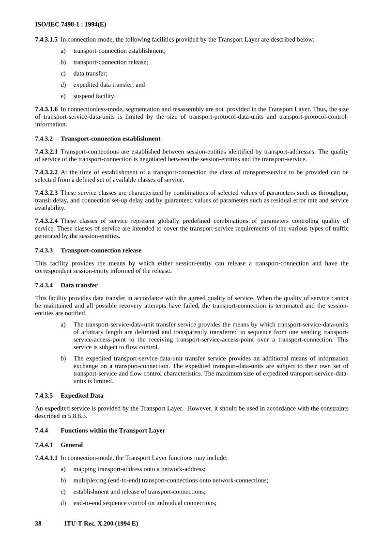
ISO/IEC 7498-1 : 1994(E)
38 ITU-T Rec. X.200 (1994 E)
7.4.3.1.5 In connection-mode, the following facilities provided by the Transport Layer are described below:
a) transport-connection establishment;
b) transport-connection release;
c) data transfer;
d) expedited data transfer; and
e) suspend facility.
7.4.3.1.6 In connectionless-mode, segmentation and resassembly are not provided in the Transport Layer. Thus, the sizeof transport-service-data-units is limited by the size of transport-protocol-data-units and transport-protocol-control-information.
7.4.3.2 Transport-connection establishment
7.4.3.2.1 Transport-connections are established between session-entities identified by transport-addresses. The qualityof service of the transport-connection is negotiated between the session-entities and the transport-service.
7.4.3.2.2 At the time of establishment of a transport-connection the class of transport-service to be provided can beselected from a defined set of available classes of service.
7.4.3.2.3 These service classes are characterized by combinations of selected values of parameters such as throughput,transit delay, and connection set-up delay and by guaranteed values of parameters such as residual error rate and serviceavailability.
7.4.3.2.4 These classes of service represent globally predefined combinations of parameters controling quality ofservice. These classes of service are intended to cover the transport-service requirements of the various types of trafficgenerated by the session-entities.
7.4.3.3 Transport-connection release
This facility provides the means by which either session-entity can release a transport-connection and have thecorrespondent session-entity informed of the release.
7.4.3.4 Data transfer
This facility provides data transfer in accordance with the agreed quality of service. When the quality of service cannotbe maintained and all possible recovery attempts have failed, the transport-connection is terminated and the session-entities are notified.
a) The transport-service-data-unit transfer service provides the means by which transport-service-data-unitsof arbitrary length are delimited and transparently transferred in sequence from one sending transport-service-access-point to the receiving transport-service-access-point over a transport-connection. Thisservice is subject to flow control.
b) The expedited transport-service-data-unit transfer service provides an additional means of informationexchange on a transport-connection. The expedited transport-data-units are subject to their own set oftransport-service and flow control characteristics. The maximum size of expedited transport-service-data-units is limited.
7.4.3.5 Expedited Data
An expedited service is provided by the Transport Layer. However, it should be used in accordance with the constraintsdescribed in 5.8.8.3.
7.4.4 Functions within the Transport Layer
7.4.4.1 General
7.4.4.1.1 In connection-mode, the Transport Layer functions may include:
a) mapping transport-address onto a network-address;
b) multiplexing (end-to-end) transport-connections onto network-connections;
c) establishment and release of transport-connections;
d) end-to-end sequence control on individual connections;
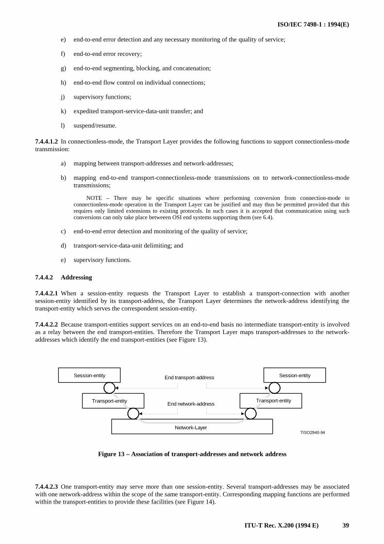
ISO/IEC 7498-1 : 1994(E)
ITU-T Rec. X.200 (1994 E) 39
e) end-to-end error detection and any necessary monitoring of the quality of service;
f) end-to-end error recovery;
g) end-to-end segmenting, blocking, and concatenation;
h) end-to-end flow control on individual connections;
j) supervisory functions;
k) expedited transport-service-data-unit transfer; and
l) suspend/resume.
7.4.4.1.2 In connectionless-mode, the Transport Layer provides the following functions to support connectionless-modetransmission:
a) mapping between transport-addresses and network-addresses;
b) mapping end-to-end transport-connectionless-mode transmissions on to network-connectionless-modetransmissions;
NOTE – There may be specific situations where performing conversion from connection-mode toconnectionless-mode operation in the Transport Layer can be justified and may thus be permitted provided that thisrequires only limited extensions to existing protocols. In such cases it is accepted that communication using suchconversions can only take place betweeen OSI end systems supporting them (see 6.4).
c) end-to-end error detection and monitoring of the quality of service;
d) transport-service-data-unit delimiting; and
e) supervisory functions.
7.4.4.2 Addressing
7.4.4.2.1 When a session-entity requests the Transport Layer to establish a transport-connection with anothersession-entity identified by its transport-address, the Transport Layer determines the network-address identifying thetransport-entity which serves the correspondent session-entity.
7.4.4.2.2 Because transport-entities support services on an end-to-end basis no intermediate transport-entity is involvedas a relay between the end transport-entities. Therefore the Transport Layer maps transport-addresses to the network-addresses which identify the end transport-entities (see Figure 13).
TISO2940-94
Session-entity Session-entity
Transport-entity Transport-entity
End transport-address
End network-address
Network-Layer
Figure 13 – Association of transport-addresses and network address
FIGURE 13/X.200...[D12] = 5.5 CM
7.4.4.2.3 One transport-entity may serve more than one session-entity. Several transport-addresses may be associatedwith one network-address within the scope of the same transport-entity. Corresponding mapping functions are performedwithin the transport-entities to provide these facilities (see Figure 14).
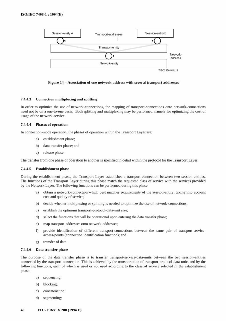
ISO/IEC 7498-1 : 1994(E)
40 ITU-T Rec. X.200 (1994 E)
TISO2950-94/d13
Session-entity A Session-entity BTransport-addresses
Transport-entity
Network-entity
Network-address
Figure 14 – Association of one network address with several transport addresses
FIGURE 14/X.200...[D13] = 5.5 CM
7.4.4.3 Connection multiplexing and splitting
In order to optimize the use of network-connections, the mapping of transport-connections onto network-connectionsneed not be on a one-to-one basis. Both splitting and multiplexing may be performed, namely for optimizing the cost ofusage of the network-service.
7.4.4.4 Phases of operation
In connection-mode operation, the phases of operation within the Transport Layer are:
a) establishment phase;
b) data transfer phase; and
c) release phase.
The transfer from one phase of operation to another is specified in detail within the protocol for the Transport Layer.
7.4.4.5 Establishment phase
During the establishment phase, the Transport Layer establishes a transport-connection between two session-entities.The functions of the Transport Layer during this phase match the requested class of service with the services providedby the Network Layer. The following functions can be performed during this phase:
a) obtain a network-connection which best matches requirements of the session-entity, taking into accountcost and quality of service;
b) decide whether multiplexing or splitting is needed to optimize the use of network-connections;
c) establish the optimum transport-protocol-data-unit size;
d) select the functions that will be operational upon entering the data transfer phase;
e) map transport-addresses onto network-addresses;
f) provide identification of different transport-connections between the same pair of transport-service-access-points (connection identification function); and
g) transfer of data.
7.4.4.6 Data transfer phase
The purpose of the data transfer phase is to transfer transport-service-data-units between the two session-entitiesconnected by the transport-connection. This is achieved by the transportation of transport-protocol-data-units and by thefollowing functions, each of which is used or not used according to the class of service selected in the establishmentphase:
a) sequencing;
b) blocking;
c) concatenation;
d) segmenting;
ISO/IEC 7498-1 : 1994(E)
ITU-T Rec. X.200 (1994 E) 41
e) multiplexing or splitting;
f) flow control;
g) error detection;
h) error recovery;
j) expedited data transfer;
k) transport-service-data-unit delimiting; and
m) transport-connection identification.
7.4.4.7 Release phase
The purpose of the release phase is to release the transport-connection. It may include the following functions:
a) notification of reason for release;
b) identificaton of the transport-connection released; and
c) transfer of data.
7.4.4.8 Transport Layer management
The Transport Layer protocols deal with some management activities of the layer (such as activation and error control).See clause 8 and ITU-T Rec. X.700 | ISO 7498-4 for the relationship with other management aspects.
7.5 Network Layer
7.5.1 Definitions
7.5.1.1 real subnetwork: A collection of equipment and physical media which forms an autonomous whole andwhich can be used to interconnect real systems for the purpose of data transfer.
7.5.1.2 subnetwork: An abstraction of a real subnetwork.
NOTES
1 A subnetwork is a representation within the OSI Reference Model of a real network such as a carrier network, aprivate network, or a local area network.
2 A subnetwork may itself be an open system, although this is not necessarily always the case. See ISO 8648 – InternalOrganization of the Network Layer.
7.5.1.3 subnetwork-connection: A communication path through a subnetwork which is used by entities in theNetwork Layer in providing a network-connection.
7.5.2 Purpose
7.5.2.1 The Network Layer provides the functional and procedural means for connectionless-mode or connection-mode transmission among transport-entities and, therefore, provides to the transport-entities independence of routing andrelay considerations.
7.5.2.2 The Network Layer provides the means to establish, maintain, and terminate network-connections betweenopen systems containing communicating application-entities and the functional and procedural means to exchangenetwork-service-data-units between transport-entities over network-connections.
7.5.2.3 It provides to the transport-entities independence from routing and relay consideration associated with theestablishment and operation of a given network-connection. This includes the case where several subnetworks are usedin tandem (see 7.5.4.2) or in parallel. It makes invisible to transport-entities how underlying resources such as data-link-connections are used to provide network-connections.
7.5.2.4 Any relay functions and hop-by-hop service enhancement protocols used to support the network-servicebetween the OSI end systems are operating below the Transport Layer, i.e. within the Network Layer or below.
7.5.3 Service provided to the Transport Layer
7.5.3.1 Introduction
7.5.3.1.1 The basic service of the Network Layer is to provide the transparent transfer of data between transport-entities.This service allows the structure and detailed content of submitted data to be determined exclusively by layers above theNetwork Layer.
ISO/IEC 7498-1 : 1994(E)
42 ITU-T Rec. X.200 (1994 E)
7.5.3.1.2 All facilities are provided to the Transport Layer at a known cost.
7.5.3.1.3 The Network Layer contains functions necessary to provide the Transport Layer with a firmNetwork/Transport Layer boundary which is independent of the underlying communications media in all things otherthan quality of service. Thus the Network Layer contains functions necessary to mask the differences in thecharacteristics of different transmission and subnetwork technologies into a consistent network service.
7.5.3.1.4 The service provided at each end of a network-connection is the same even when a network-connection spansseveral subnetworks, each offering dissimilar services (see 7.5.4.2).
NOTE – It is important to distinguish the specialized use of the term “service” within the OSI Reference Model from itscommon use by suppliers of private networks and carriers.
7.5.3.1.5 The quality of service is negotiated between the transport-entities and the network-service at the time ofestablishment of a network-connection. While this quality of service may vary from one network-connection to anotherit will be agreed for a given network-connection and be the same at both network-connection-endpoints.
7.5.3.1.6 In connection-mode, the facilities provided by the Network Layer are described below:
a) network-addresses;
b) network-connections;
c) network-connection-endpoint-identifiers;
d) network-service-data-unit transfer;
e) quality of service parameters;
f) error notification;
g) expedited network-service-data-unit transfer ;
h) reset;
j) release; and
k) receipt of confirmation.
7.5.3.1.7 Some of these facilities are optional. This means that:
a) the user has to request the facilities; and
b) the network-service provider may honour the request or indicate that the service is not available.
7.5.3.1.8 In connectionless-mode, the facilities provided by the Network Layer, operating among network-service-access-points, are:
a) transmission of network-service-data-units of a defined maximum size;
b) quality of service parameters; and
c) local error notification.
7.5.3.2 Network-addresses
Transport-entities are known to the Network Layer by means of network-addresses. Network-addresses are provided bythe Network Layer and can be used by transport-entities to identify uniquely other transport-entities, i.e. network-addresses are necessary for transport-entities to communicate using the network-service. The Network Layer uniquelyidentifies each of the end open systems (represented by transport-entities) by their network-addresses. This may beindependent of the addressing needed by the underlaying layers.
7.5.3.3 Network-connections
7.5.3.3.1 A network-connection provides the means of transferring data between transport-entities identified bynetwork-SAP-addresses. The Network Layer provides the means to establish, maintain and release network-connections.
7.5.3.3.2 A network-connection is point-to-point.
7.5.3.3.3 More than one network-connection may exist between the same pair of transport-entities (through the network-SAP-addresses).
7.5.3.4 Network-connection-endpoint-identifiers
The Network Layer provides to the transport-entity a network-connection-endpoint-identifier which uniquely identifiesthe network-connection-endpoint with the associated network-SAP-address.
ISO/IEC 7498-1 : 1994(E)
ITU-T Rec. X.200 (1994 E) 43
7.5.3.5 Network-service-data-unit transfer
7.5.3.5.1 On a network-connection, the Network Layer provides for the transmission of network-service-data-units.These units have a distinct beginning and end and the integrity of the unit’s content is maintained by the Network Layer.
7.5.3.5.2 In connection-mode, no limit is imposed on the maximum size of network-service-data-units.
7.5.3.5.3 The network-service-data-units are transferred transparently between transport-entities.
7.5.3.6 Quality of service parameters
7.5.3.6.1 The Network Layer establishes and maintains a selected qualilty of service for the duration of the network-connection.
7.5.3.6.2 The quality of service parameters include residual error rate, service availability, reliability, throughput, transitdelay (including variations), and delay for network-connection establishment.
7.5.3.7 Error notification
7.5.3.7.1 Unrecoverable errors detected by the Network Layer are reported to the transport-entities.
7.5.3.7.2 Error notification may or may not lead to the release of the network-connection, according to the specificationof a particular network-service.
7.5.3.8 Expedited network-service-data-unit transfer
7.5.3.8.1 The expedited network-service-data-unit transfer is optional and provides an additional means of informationexchange on a network-connection. The transfer of a expedited network-service-data-units is subject to a different set ofnetwork-service characteristics and to separate flow control.
7.5.3.8.2 The maximum size of an expedited network-service-data-unit is limited.
7.5.3.8.3 This service is an optional service that may not always be available.
7.5.3.9 Reset
The reset facility is optional and when invoked causes the Network Layer to discard all network-service-data-units intransit on the network-connection and to notify the transport-entity at the other end of the network-connection that areset has occurred.
7.5.3.10 Release
7.5.3.10.1 A transport-entity may request release of a network-connection. The network-service does not guaranteedelivery of data preceding the release request and still in transit. The network-connection is released regardless of theaction taken by the correspondent transport-entity.
7.5.3.10.2 This facility is optional and may not always be available.
7.5.3.11 Receipt confirmation
7.5.3.11.1 A transport-entity may confirm receipt of data over a network-connection. The use of the receiptconfirmation service is agreed by the two users of the network-connection during connection establishment.
7.5.3.11.2 This service is optional and may not always be available.4)
7.5.4 Functions within the Network Layer
7.5.4.1 Introduction
7.5.4.1.1 Network Layer functions provide for the wide variety of configurations supporting network-connectionsranging from network-connections supported by point-to-point configurations to network-connections supported bycomplex combinations of subnetworks with different characteristics.
NOTE – In order to cope with this wide variety of cases, network functions should be structured into sublayers. Thesubdivision of the Network Layer into sublayers need only be done when this is useful. In particular, sublayering need not be usedwhen the access protocol to the subnetwork supports the complete functionality of the OSI network-service.
_______________4) This service is included in the network-service only to support existing features of ITU-T Rec. X.25.
ISO/IEC 7498-1 : 1994(E)
44 ITU-T Rec. X.200 (1994 E)
7.5.4.1.2 The following are functions performed by the Network Layer:
a) routing and relaying;
b) network-connections;
c) network-connection multiplexing;
d) segmenting and blocking;
e) error detection;
f) error recovery;
g) sequencing;
h) flow control;
j) expedited data transfer;
k) reset;
m) service selection;
n) mapping between network-addresses and data-link addresses;
o) mapping network-connectionless-mode transmissions to data-link-connectionless-mode transmissions;
p) converting from data-link-connection-mode service to network-connectionless-mode service;
q) enhancing a data-link-connectionless mode service to provide a network-connection-mode service; and
r) network layer management.
7.5.4.2 Routing and relaying
7.5.4.2.1 Network-connections are provided by network-entities in OSI end systems and by intermediate open systemswhich provide relaying. These intermediate open systems may interconnect subnetwork-connections, data-link-connections, and data-circuits (see 7.7). Routing functions determine an appropriate route between network-addresses. Inorder to set up the resulting communication, it may be necessary for the Network Layer to use the services of the DataLink Layer to control the interconnection of data-circuits (see 7.6.4.10 and 7.7.3.1).
7.5.4.2.2 The control of interconnection of data-circuits (which are in the Physical Layer) from the Network Layerrequires interaction between a network-entity and a physical-entity in the same open system. Since the Reference Modelpermits direct interaction only between adjacent layers, the network-entity cannot interact directly with the physical-entity. This interaction is thus described through the Data Link Layer which intervenes transparently to convey theinteraction between the Network Layer and the Physical Layer.
7.5.4.2.3 This representation of the control of data-circuit interconnection is an abstract representation. It is a localmatter in an open system. It does not model the functioning of real open systems and as such has no impact on thestandardization of OSI protocols.
NOTE – When Network Layer functions are performed by combinations of several individual subnetworks, thespecification of routing and relaying functions could be facilitated by using sublayers, isolating individual subnetworks routing andrelaying functions from internetwork routing and relaying functions. However, when subnetworks have access protocols supportingthe complete functionality of the OSI network service, there need be no sublayering in the Network Layer.
7.5.4.3 Network-connections
7.5.4.3.1 This function provides network-connections between transport-entities, making use of data-link-connectionsprovided by the Data Link Layer.
7.5.4.3.2 A network-connection may also be provided as subnetwork-connections in tandem, i.e. using severalindividual subnetworks in series. The interconnected individual subnetworks may have the same or different servicecapabilities. Each end of a subnetwork-connection may operate with a different subnetwork protocol.
7.5.4.3.3 The interconnection of a pair of subnetworks of differing qualities may be achieved in two ways. To illustratethese, consider a pair of subnetworks, one of high quality and the other of low quality:
a) The two subnetworks are interconnected as they stand. The quality of the resulting network-connection isnot higher than that of the lower quality subnetwork (see Figure 15).
b) The lower quality subnetwork is enhanced to equal the higher quality subnetwork and the subnetworksare then interconnected. The quality of the resulting network-connection is approximately that of thehigher quality subnetwork (see Figure 16).
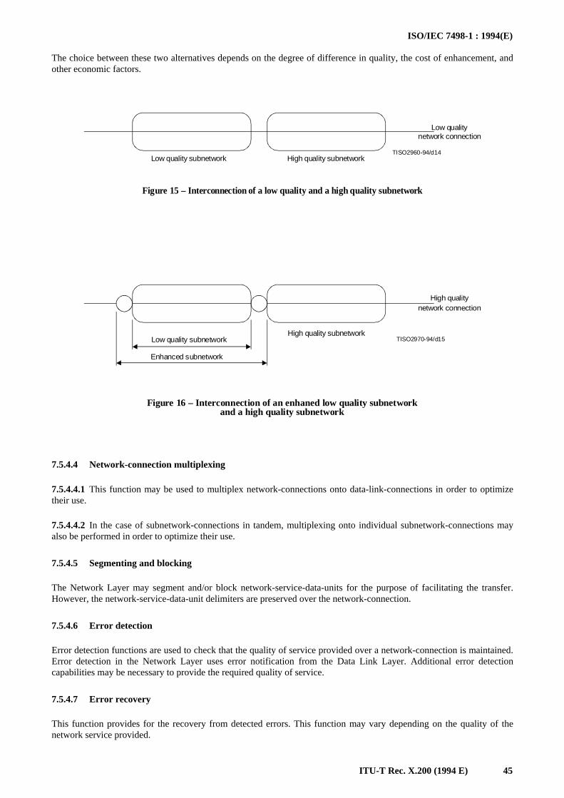
ISO/IEC 7498-1 : 1994(E)
ITU-T Rec. X.200 (1994 E) 45
The choice between these two alternatives depends on the degree of difference in quality, the cost of enhancement, andother economic factors.
TISO2960-94/d14
Low qualitynetwork connection
Low quality subnetwork High quality subnetwork
Figure 15 – Interconnection of a low quality and a high quality subnetwork
FIGURE 15/X.200...[D14] = 3.5 CM
TISO2970-94/d15
High qualitynetwork connection
Low quality subnetworkHigh quality subnetwork
Enhanced subnetwork
Figure 16 – Interconnection of an enhaned low quality subnetworkand a high quality subnetwork
FIGURE 16/X.200...[D15] = 5 CM
7.5.4.4 Network-connection multiplexing
7.5.4.4.1 This function may be used to multiplex network-connections onto data-link-connections in order to optimizetheir use.
7.5.4.4.2 In the case of subnetwork-connections in tandem, multiplexing onto individual subnetwork-connections mayalso be performed in order to optimize their use.
7.5.4.5 Segmenting and blocking
The Network Layer may segment and/or block network-service-data-units for the purpose of facilitating the transfer.However, the network-service-data-unit delimiters are preserved over the network-connection.
7.5.4.6 Error detection
Error detection functions are used to check that the quality of service provided over a network-connection is maintained.Error detection in the Network Layer uses error notification from the Data Link Layer. Additional error detectioncapabilities may be necessary to provide the required quality of service.
7.5.4.7 Error recovery
This function provides for the recovery from detected errors. This function may vary depending on the quality of thenetwork service provided.
ISO/IEC 7498-1 : 1994(E)
46 ITU-T Rec. X.200 (1994 E)
7.5.4.8 Sequencing
This function provides for the sequenced delivery of network-service-data-units over a given network-connection whenrequested by a transport-entity.
7.5.4.9 Flow control
If flow control is required, this function may need to be performed.
7.5.4.10 Expedited data transfer
This function provides for the expedited data transfer facility.
7.5.4.11 Reset
This function provides for the reset service.
7.5.4.12 Service selection
This function allows service selection to be carried out to ensure that the service provided at each end of a network-connection is the same when a network-connection spans several subnetworks of dissimilar quality.
7.5.4.13 Network Layer management
The Network Layer protocols deal with some management activities of the layer (such as activation and error control).See clause 8 and ITU-T Rec. X.700 | ISO 7498-4 for the relationship with other management aspects.
7.6 Data Link Layer
7.6.1 Definitions
No Data Link Layer specific terms are identified.
7.6.2 Purpose
7.6.2.1 The Data Link Layer provides functional and procedural means for connectionless-mode amongnetwork-entities, and for connection-mode for the establishment, maintenance, and release data-link-connections amongnetwork-entities and for the transfer of data-link-service-data-units. A data-link-connection is built upon one or severalphysical-connections.
7.6.2.2 The Data Link Layer detects and possibly corrects errors which may occur in the Physical Layer.
7.6.2.3 In addition, the Data Link Layer enables the Network Layer to control the interconnection of data-circuitswithin the Physical Layer.
7.6.3 Service provided to the Network Layer
7.6.3.1 In connection-mode, the facilities provided by the Data Link Layer are:
a) data-link-addresses;
b) data-link-connection;
c) data-link-service-data-units;
d) data-link-connection-endpoint-identifiers;
e) error notification;
f) quality of service parameters; and
g) reset.
7.6.3.2 In connectionless-mode, the facilities provided by the Data Link Layer are:
a) data-link-addresses;
b) transmission of data-link-service-data-units of a defined maximum size; and
c) quality of service parameters.
ISO/IEC 7498-1 : 1994(E)
ITU-T Rec. X.200 (1994 E) 47
7.6.3.3 Data-link-addresses
Network-entities are known to the Data Link Layer by means of data-link-addresses. Data-link-addresses are providedby the Data Link Layer and can be used by network-entities to identify other network-entities which communicate usingthe data link service. A data-link-address is unique within the scope of the set of Open Systems attached to a commonData Link Layer. The notion of a data-link-address is distinct from that of a data-link-service-access-point-address(DLSAP address).
7.6.3.4 Data-link-connection
A data-link-connection provides the means of transferring data between network-entities identified by data-link-addresses. A data-link-connection is established and released dynamically.
7.6.3.5 Data-link-service-data-units
7.6.3.5.1 The Data Link Layer allows exchange of data-link-service-data-units over a data-link-connection or exchangeof data-link-service-data-units (that bear no relation to any other data-link-service-data-units) using the connectionless-mode data-link-service.
7.6.3.5.2 The size of the data-link-service-data-units may be limited by the relationship between the physical-connectionerror rate and the Data Link Layer error detection capability.
7.6.3.6 Data-link-connection-endpoint-identifiers
If needed, the Data Link Layer provides data-link-connection-endpoint-identifiers that can be used by a network-entityto identify a correspondent network-entity.
7.6.3.7 Error notification
Notification is provided to the network-entity when any unrecoverable error is detected by the Data Link Layer.
7.6.3.8 Quality of service parameters
Quality of service parameters may be optionally selectable. The Data Link Layer establishes and maintains a selectedquality of service for the duration of the data-link-connection. The quality of service parameters include mean timebetween detected but unrecoverable errors, residual error rate (where errors may arise from alteration, loss, duplication,misordering, misdelivery of data-link-service-data-units, and other causes), service availability, transit delay andthroughput.
7.6.3.9 Reset
The network-entity can force the data-link-entity-invocation into a known state by invoking the reset facility.
7.6.4 Functions within the Data Link Layer
In connection-mode and connectionless-mode, the functions performed by the Data Link Layer are:
a) data-link-service-data-unit mapping;
b) identification and parameter exchange;
c) control of data-circuit interconnection;
d) error detection;
e) routing and relaying; and
f) data Link Layer management.
In connection-mode, the following functions are also performed by the Data Link Layer:
a) data-link-connection establishment and release;
b) connection-mode data-link data transmission;
c) data-link-connection splitting;
d) sequence control;
e) delimiting and synchronization;
ISO/IEC 7498-1 : 1994(E)
48 ITU-T Rec. X.200 (1994 E)
f) flow control;
g) error recovery; and
h) reset.
In connectionless-mode, the following function is also performed by the Data Link Layer:
a) connectionless-mode data-link data transmission.
7.6.4.1 Data-link-connection establishment and release
These functions establish and release data-link-connections on activated physical-connections. When a physical-connection has multiple endpoints (for example multipoint connection) a specific function is needed within the DataLink Layer to identify the data-link-connections using such a physical-connection.
7.6.4.2 Connectionless-mode data-link-data transmission
The connectionless-mode data-link-data transmission provides the means for the transmission of data-link-service-data-units between data-link-service-access-points without establishing a data-link-connection.
7.6.4.3 Data-link-service-data-unit mapping
This function maps data-link-service-data-units into data-link-protocol-data-units on a one-to-one basis.
NOTE – More general mappings are for further study.
7.6.4.4 Data-link-connection splitting
This function performs splitting of one data-link-connection onto several physical-connections.
7.6.4.5 Delimiting and synchronization
These functions provide recognition of a sequence of physical-service-data-units (i.e. bits, see 7.7.3.2) transmitted overthe physical-connection, as a data-link-protocol-data-unit.
NOTE – These functions are sometimes referred to as framing.
7.6.4.6 Sequence control
This function maintains the sequential order of data-link-service-data-units across a data-link-connection.
7.6.4.7 Error detection
This function detects transmission, format and operational errors occurring either on the physical-connection, or as aresult of a malfunction of the correspondent data-link-entity.
7.6.4.8 Error recovery
This function attempts to recover from detected transmission, format and operational errors and notifies the network-entities of errors which are unrecoverable.
7.6.4.9 Flow control
In connection-mode, each network-entity can dynamically control (up to the agreed maximum) the rate at which itreceives data-link-service-data-units from a data-link-connection. This control may be reflected in the rate at whichthe Data Link Layer accepts data-link-service-data-units at the correspondent data-link-connection-endpoint. Inconnectionless-mode, there is service boundary flow control, but no peer flow control.
7.6.4.10 Identification and parameter exchange
This function performs data-link-entity identification and parameter exchange.
7.6.4.11 Reset
This function performs a data-link reset forcing the data-link-entity-invocation to a known state.
7.6.4.12 Control of data-circuit interconnection
This function conveys to network-entities the capability of controlling the interconnection of data-circuits within thePhysical Layer.
ISO/IEC 7498-1 : 1994(E)
ITU-T Rec. X.200 (1994 E) 49
NOTE – This function is used in particular when a physical-connection is established/released across a circuit-switchedsubnetwork by relaying within an intermediate system between data-circuits. These data-circuits are elements of the end-to-end path.A network-entity in the intermediate system makes the appropriate routing decisions as a function of the path requirements derivedfrom the network signalling protocols.
7.6.4.13 Routing and Relaying
Some subnetworks, and particularly some configurations of local area networks, require that routing and relayingbetween individual local networks be performed in the data-link-layer.
7.6.4.14 Data Link Layer management
The Data Link Layer protocols deal with some management activities of the layer (such as activiation and error control).See clause 8 and ITU-T Rec. X.700 | ISO 7498-4 for the relationship with other management aspects.
7.7 Physical Layer
7.7.1 Definition
7.7.1.1 data-circuit: A communication path in the physical media for OSI among two or more physical-entities,together with the facilities necessary in the Physical Layer for the transmission of bits on it.
7.7.2 Purpose
The Physical Layer provides the mechanical, electrical, functional and procedural means to activate, maintain, andde-activate physical-connections for bit transmission between data-link-entities. A physical-connection may involveintermediate open systems, each relaying bit transmission within the Physical Layer. Physical Layer entities areinterconnected by means of a physical medium.
7.7.3 Services provided to the Data Link Layer
7.7.3.1 The services provided by the Physical Layer are determined by the characteristics of the underlying mediumand are too diverse to allow categorization into connection-mode and connectionless-mode.
7.7.3.2 The services or elements of services are provided by the Physical Layer:
a) physical-connections;
b) physical-service-data-units;
c) physical-connection-endpoints;
d) data-circuit identification;
e) sequencing;
f) fault condition notification; and
g) quality of service parameters.
7.7.3.3 Physical-connections
7.7.3.3.1 The Physical Layer provides for the transparent transmission of bit streams between data-link-entities acrossphysical-connections.
7.7.3.3.2 A data-circuit is a communication path in the physical media for OSI among two or more physical-entities,together with the facilities necessary in the Physical Layer for the transmission of bits on it.
7.7.3.3.3 A physical-connection may be provided by the interconnection of data-circuits using relaying functions in thePhysical Layer. The provision of a physical-connection by such an assembly of data-circuits is illustrated in Figure 17.
7.7.3.3.4 The control of the interconnection of data-circuits is offered as a service to data-link-entities.
7.7.3.4 Physical-service-data-units
7.7.3.4.1 A physical-service-data-unit consists of one bit or a string of bits.
NOTE – Serial or parallel transmission can be accommodated by the design of the protocol within the Physical Layer.
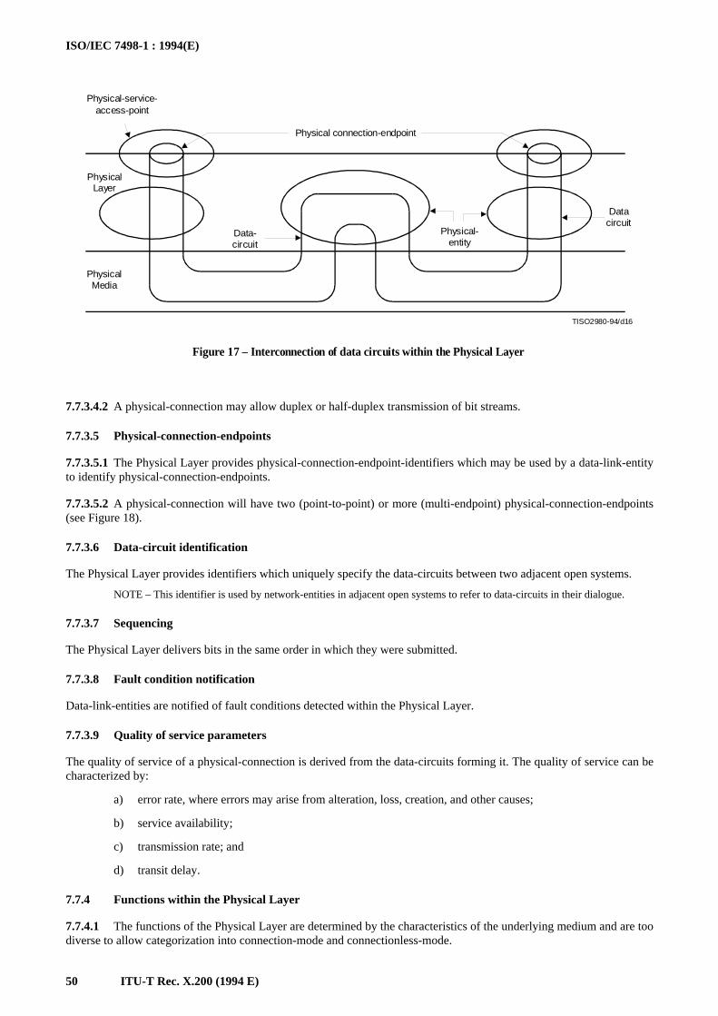
ISO/IEC 7498-1 : 1994(E)
50 ITU-T Rec. X.200 (1994 E)
TISO2980-94/d16
Physical-service-access-point
Physical connection-endpoint
PhysicalLayer
Data-circuit
Physical-entity
Datacircuit
PhysicalMedia
Figure 17 – Interconnection of data circuits within the Physical Layer
FIGURE 17/X.200...[D16] = 8 CM
7.7.3.4.2 A physical-connection may allow duplex or half-duplex transmission of bit streams.
7.7.3.5 Physical-connection-endpoints
7.7.3.5.1 The Physical Layer provides physical-connection-endpoint-identifiers which may be used by a data-link-entityto identify physical-connection-endpoints.
7.7.3.5.2 A physical-connection will have two (point-to-point) or more (multi-endpoint) physical-connection-endpoints(see Figure 18).
7.7.3.6 Data-circuit identification
The Physical Layer provides identifiers which uniquely specify the data-circuits between two adjacent open systems.
NOTE – This identifier is used by network-entities in adjacent open systems to refer to data-circuits in their dialogue.
7.7.3.7 Sequencing
The Physical Layer delivers bits in the same order in which they were submitted.
7.7.3.8 Fault condition notification
Data-link-entities are notified of fault conditions detected within the Physical Layer.
7.7.3.9 Quality of service parameters
The quality of service of a physical-connection is derived from the data-circuits forming it. The quality of service can becharacterized by:
a) error rate, where errors may arise from alteration, loss, creation, and other causes;
b) service availability;
c) transmission rate; and
d) transit delay.
7.7.4 Functions within the Physical Layer
7.7.4.1 The functions of the Physical Layer are determined by the characteristics of the underlying medium and are toodiverse to allow categorization into connection-mode and connectionless-mode.
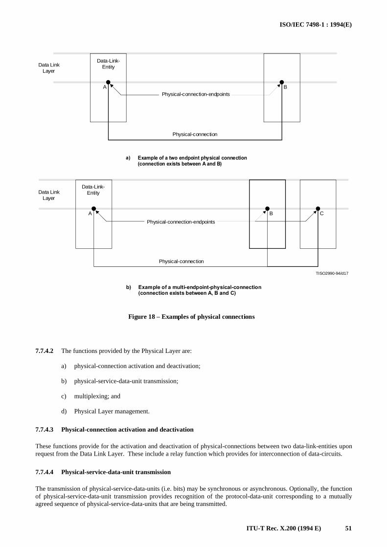
ISO/IEC 7498-1 : 1994(E)
ITU-T Rec. X.200 (1994 E) 51
A B
A B C
TISO2990-94/d17
Data LinkLayer
Data-Link-Entity
Physical-connection-endpoints
Physical-connection
%XAMPLE�OF�A�TWO�ENDPOINT�PHYSICAL�CONNECTION�CONNECTION�EXISTS�BETWEEN�!�AND�"
A
Data LinkLayer
Data-Link-Entity
Physical-connection-endpoints
Physical-connection
%XAMPLE�OF�A�MULTI ENDPOINT PHYSICAL CONNECTION�CONNECTION�EXISTS�BETWEEN�!��"�AND�#
B
Figure 18 – Examples of physical connections
FIGURE 18/X.200...[D17] = 15 CM
7.7.4.2 The functions provided by the Physical Layer are:
a) physical-connection activation and deactivation;
b) physical-service-data-unit transmission;
c) multiplexing; and
d) Physical Layer management.
7.7.4.3 Physical-connection activation and deactivation
These functions provide for the activation and deactivation of physical-connections between two data-link-entities uponrequest from the Data Link Layer. These include a relay function which provides for interconnection of data-circuits.
7.7.4.4 Physical-service-data-unit transmission
The transmission of physical-service-data-units (i.e. bits) may be synchronous or asynchronous. Optionally, the functionof physical-service-data-unit transmission provides recognition of the protocol-data-unit corresponding to a mutuallyagreed sequence of physical-service-data-units that are being transmitted.
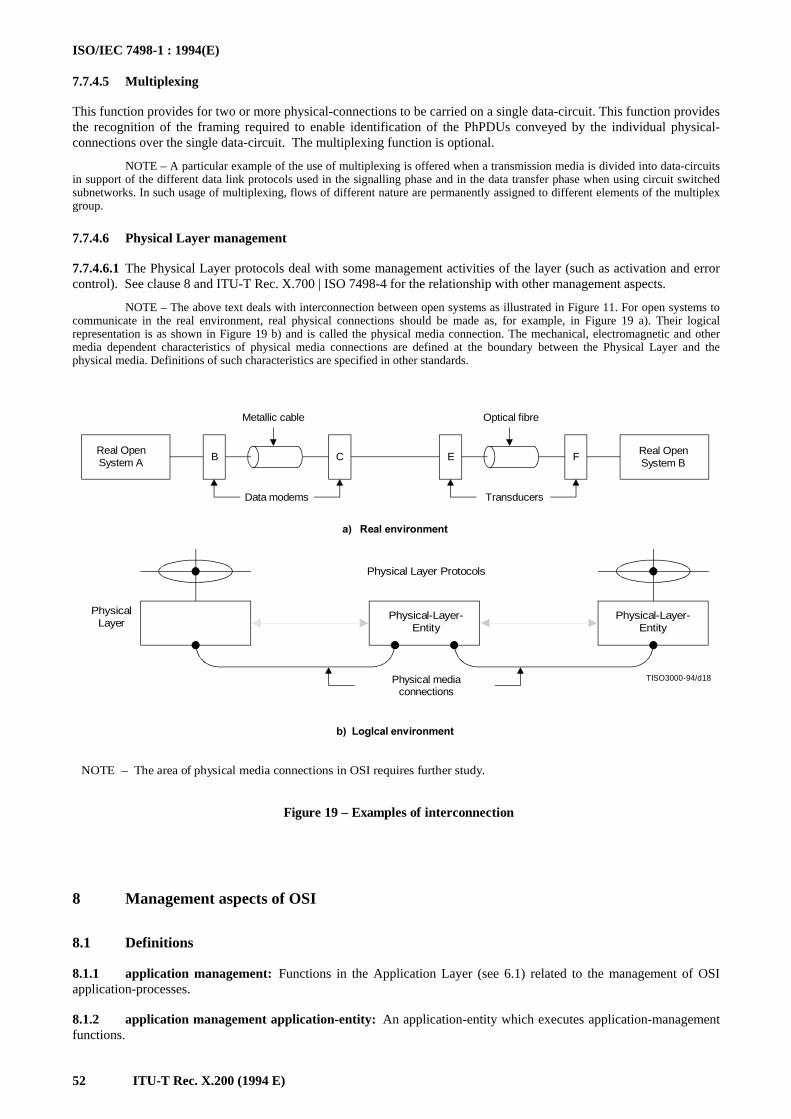
ISO/IEC 7498-1 : 1994(E)
52 ITU-T Rec. X.200 (1994 E)
7.7.4.5 Multiplexing
This function provides for two or more physical-connections to be carried on a single data-circuit. This function providesthe recognition of the framing required to enable identification of the PhPDUs conveyed by the individual physical-connections over the single data-circuit. The multiplexing function is optional.
NOTE – A particular example of the use of multiplexing is offered when a transmission media is divided into data-circuitsin support of the different data link protocols used in the signalling phase and in the data transfer phase when using circuit switchedsubnetworks. In such usage of multiplexing, flows of different nature are permanently assigned to different elements of the multiplexgroup.
7.7.4.6 Physical Layer management
7.7.4.6.1 The Physical Layer protocols deal with some management activities of the layer (such as activation and errorcontrol). See clause 8 and ITU-T Rec. X.700 | ISO 7498-4 for the relationship with other management aspects.
NOTE – The above text deals with interconnection between open systems as illustrated in Figure 11. For open systems tocommunicate in the real environment, real physical connections should be made as, for example, in Figure 19 a). Their logicalrepresentation is as shown in Figure 19 b) and is called the physical media connection. The mechanical, electromagnetic and othermedia dependent characteristics of physical media connections are defined at the boundary between the Physical Layer and thephysical media. Definitions of such characteristics are specified in other standards.
B C E F
TISO3000-94/d18
Real OpenSystem A
Metallic cable Optical fibre
Real OpenSystem B
Data modems Transducers
A���2EAL�ENVIRONMENT
Physical Layer Protocols
Physical Layer
Physical-Layer-Entity
Physical-Layer-Entity
Physical mediaconnections
B��,OGLCAL�ENVIRONMENT
Figure 19 – Examples of interconnection
NOTE – The area of physical media connections in OSI requires further study.
FIGURE 19/X.200...[D18] = 11 CM
8 Management aspects of OSI
8.1 Definitions
8.1.1 application management: Functions in the Application Layer (see 6.1) related to the management of OSIapplication-processes.
8.1.2 application management application-entity: An application-entity which executes application-managementfunctions.
ISO/IEC 7498-1 : 1994(E)
ITU-T Rec. X.200 (1994 E) 53
8.1.3 OSI resources: Data processing and data communication resources which are of concern to OSI.
8.1.4 systems management: Functions in the Application Layer related to the management of various OSIresources and their status across all layers of the OSI architecture.
8.1.5 systems management application-entity: An application-entity for the purposes of systems-managementcommunications.
8.1.6 layer management: Functions related to the management of the (N)-layer partly performed in the (N)-layeritself according to the (N)-protocol of the layer (activities such as activation and error control) and partly performed as asubset of systems-management.
8.2 Introduction
8.2.1 Within the OSI Reference Model, there is a need to recognize the special problems of initiating, terminating,and monitoring activities and assisting in their harmonious operations, as well as handling abnormal conditions. Thesehave been collectively considered as the management aspects of the OSI architecture. These concepts are essential to theoperation of the interconnected open systems.
8.2.2 The management activities which are of concern are those which imply actual exchanges of informationbetween open systems. Only the protocols needed to conduct such exchanges are candidates for standardization withinthe OSIE.
8.2.3 This clause describes key concepts relevant to the management aspects, including the different categories ofmanagement activities and the positioning of such activities within the OSI Reference Model.
8.2.4 Systems and layer management provide the initialization action to establish support for connectionless-modeservices between systems.
8.2.5 Management facilities may be provided to allow characteristics of the nature, quality and type ofconnectionless-mode service provided by a layer to be conveyed to the next higher layer prior to the invocation of thatservice. These facilities may provide this information either prior to any invocation of the service or at any time during aperiod when it is available.
8.3 Categories of management activities
8.3.1 Introduction
8.3.1.1 Only those management activities which imply actual exchanges of information between remote managemententities are pertinent to the OSI architecture. Other management activities local to particular open systems are outside itsscope.
8.3.1.2 Similarly, not all resources are pertinent to OSI. This International Standard considers only OSI resources,i.e. those data processing and data communication resources which are of concern to OSI.
8.3.1.3 The following categories of management activities are identified:
a) application management;
b) systems management; and
c) layer management.
8.3.2 Application-management
8.3.2.1 Application-management relates to the management of OSI application-processes. The following list is typicalof activities which fall into this category but it is not exhaustive:
a) initialization of parameters representing application-processes;
b) initiation, maintenance, and termination of application-processes;
c) allocation and de-allocation of OSI resources to application-processes;
d) detection and prevention of OSI resource interference and deadlock;
e) integrity and commitment control;
f) security control; and
g) checkpointing and recovery control.
ISO/IEC 7498-1 : 1994(E)
54 ITU-T Rec. X.200 (1994 E)
8.3.2.2 The protocols for application-management reside within the Application Layer, and are handled byapplication-management-application-entities.
8.3.3 Systems-management
8.3.3.1 Systems-management relates to the management of OSI resources and their status across all layers of the OSIReference Model. The following list is typical of activities which fall into this category but it is not exhaustive:
a) activation/deactivation management which includes:
1) activation, maintenance, and termination of OSI resources distributed in open systems, includingphysical media for OSI:
2) some program loading functions;
3) establishment/maintenance/ release of connections between management entities; and
4) open systems parameter initialization/modification;
b) monitoring which includes:
1) reporting status or status changes; and
2) reporting statistics; and
c) error control which includes:
1) error detection and some of the diagnostic functions; and
2) reconfiguration and restart.
8.3.3.2 The protocols for systems-management reside in the application-layer, and are handled by systems-management-application-entities.
8.3.4 Layer-management
8.3.4.1 There are two aspects of layer-management. One of these is concerned with layer activities such as activationand error control. This aspect is implemented by the layer protocol to which it applies.
8.3.4.2 The other aspect of layer-management is a subset of systems-management. The protocols for these activitiesreside within the Application Layer and are handled by systems-management-application-entities.
8.4 Principles for positioning management functions
Several principles are important in positioning management functions in the Reference Model of Open SystemsInterconnection. They include the following:5)
a) both centralization and decentralization of management functions are allowed. Thus, the OSI ReferenceModel does not dictate any particular fashion or degree of centralization of such functions. This principlecalls for a structure in which each open system is allowed to include any (subset of) systems-managementfunctions and each subsystem is allowed to include any (subset of) layer-management functions;
b) if it is necessary, connections between management entities are established when an open system whichhas been operating in isolation from other open systems, becomes part of the OSIE.
9 Compliance and Consistency with this reference model
9.1 Definitions
9.1.1 consistency: A “referencing” ITU-T Recommendation | International Standard is said to be consistent with a“referenced” ITU-T Recommendation | International Standard if it does not alter their meanings.
9.1.2 compliance: A “referencing” ITU-T Recommendation | International Standard is said to comply with theapplicable requirements of a “referenced” ITU-T Recommendation | International Standard if the following are true:
a) the “referenced” ITU-T Recommendation | International Standard specifies requirements (using the verb“shall”) which are applicable to the type of ITU-T Recommendation | International Standard of which the“referencing” ITU-T Recommendation | International Standard is an instance;
_______________5) Other principles are for further study.
ISO/IEC 7498-1 : 1994(E)
ITU-T Rec. X.200 (1994 E) 55
b) the “referenced” ITU-T Recommendation | International Standard includes a compliance clause to clarifywhich requirements apply to the type of ITU-T Recommendation | International Standard of which the“referencing” ITU-T Recommendation | International Standard is an instance;
c) the “referencing” ITU-T Recommendation | International Standard contains a claim of compliance to the“referenced” ITU-T Recommendation | International Standard; or
d) it is possible by inspection of the “referencing” ITU-T Recommendation | International Standard to verifythat the applicable requirements have been fulfilled.
9.2 Application of consistency and compliance requirements
9.2.1 Other modelling ITU-T Recommendations | International Standards which extend or refine this BasicReference Model shall be consistent with this part of it.
9.2.2 Compliance and consistency with this Basic Reference Model is also applicable to ITU-T Recommendations,International standards and technical reports which describe or specify OSI functions. These ITU-T Recommendations,International standards and reports can be architecture documents, models, frameworks, service definitions, or protocolspecifications.
9.2.3 Consistency
9.2.3.1 An architecture, a framework, a multilayer model, a single layer model, a service definition, or a protocolspecification consistent with this Basic Reference Model and other modelling ITU-T Recommendations | InternationalStandards which extend or refine this Basic Reference Model shall state:
“This architecture, multilayer model, single layer model, service description, or protocol specification:
a) follows the architectural principles and prescriptions of the OSI Basic Reference Model (ITU-TRec. X.200 | ISO/IEC 7498-1);
b) uses the concepts established by the OSI Basic Reference Model (ITU-T Rec. X.200 | ISO/IEC 7498-1)with identical definitions and terminology.”
9.2.4 Compliance
9.2.4.1 Compliance of an architecture, framework, or multilayer model
An architecture, a framework, or a multilayer model compliant with this Basic Reference Model and other modelingITU-T Recommendations | International Standards associated with this Basic Reference Model which refine this BasicReference Model shall state:
“This architecture, framework, or multilayer model is compliant with the OSI Basic Reference Model(ITU-T Rec. X.200 | ISO/IEC 7498-1) in that it describes operations and mechanisms which are assignable tolayers as specified in the OSI Basic Reference Model.”
9.2.4.2 Compliance of a single layer model
A single layer model compliant with this OSI Basic Reference Model shall state:
“This single layer standard is compliant with the OSI Basic Reference Model (ITU-T Rec. X.200 |ISO/IEC 7498-1) in that it describes operations and mechanisms which pertain to a particular layer as specifiedin the relevant subclause of clause 7 of the OSI Basic Reference Model.”
9.2.4.3 Compliance of a service definition
A service definition compliant with OSI Basic Reference Model shall state:
“This service definition is compliant with the OSI Basic Reference Model (ITU-T Rec. X.200 |ISO/IEC 7498-1) in that it describes facilities which pertain to a particular layer as specified in the relevantsubclause of clause 7 of the OSI Basic Reference Model.”
9.2.4.4 Compliance of a protocol specification
A protocol specification compliant with the OSI Basic Reference Model shall state:
“This protocol specification is compliant with the OSI Basic Reference Model (ITU-T Rec. X.200 |ISO/IEC 7498-1) in that it describes functions which pertain to a particular layer as specified in the relevantsubclause of clause 7 of the OSI Basic Reference Model.”
ISO/IEC 7498-1 : 1994(E)
56 ITU-T Rec. X.200 (1994 E)
Annex ABrief explanation of how the layers were chosen
(This annex does not form an integral part of this Recommendation | International Standard)
A.1 This annex provides elements giving additional information to this Recommendation | International Standard.
A.2 The following is a brief explanation of how the layers were chosen:
A.2.1 It is essential that the architecture permits usage of a realistic variety of physical media for interconnectionwith different control procedures (for example ITU-T Recs. V.24, V.25, etc.). Application of principles in 6.2 c), e)and h) leads to identification of a Physical Layer as the lowest layer in the architecture.
A.2.2 Some physical communication media (for example, telephone line) require specific techniques to be used inorder to transmit data between systems despite a relatively high error rate (i.e. an error rate not acceptable for the greatmajority of applications). These specific techniques are used in data-link control procedures which have been studiedand standardized for a number of years. It must also be recognized that new physical communication media (forexample, fibre optics) will require different data-link control procedures. Application of principles in 6.2 c), e) and h)leads to identification of a Data Link Layer on top of the Physical Layer in the architecture.
A.2.3 In the open systems architecture, some open systems will act as the final destination of data, see clause 4.Some open systems may act only as intermediate nodes [(forwarding data to other systems) (see Figure 13)]. Applicationof principles in 6.2 c), e) and g) leads to identification of a Network Layer on top of the Data Link Layer. Networkoriented protocols such as routing, for example, will be grouped in this layer. Thus, the Network Layer will provide aconnection path (network-connection) between a pair transport-entities; including the case where intermediate nodes areinvolved, see Figure 12 (see also 7.5.4.2).
A.2.4 Control of data transportation from source end open system to destination end open system (which is notperformed in intermediate nodes) is the last function to be performed in order to provide the totality of the transport-service. Thus, the upper layer in the transport-service part of the architecture is the Transport Layer, on top of theNetwork Layer. This Transport Layer relieves higher layer entities from any concern with the transportation of databetween them.
A.2.5 There is a need to organize and synchronize dialogue, and to manage the exchange of data. Application ofprinciples in 6.2 c) and d) leads to the identification of a Session Layer on top of the Transport Layer.
A.2.6 The remaining set of general interest functions are those related to representation and manipulation ofstructured data for the benefit of application programs. Application of principles in 6.2 c) and d) leads to identification ofa Presentation Layer on top of the Session Layer.
A.2.7 Finally, there are applications consisting of application-processes which perform information processing. Anaspect of these application-processes and the protocols by which they communicate comprise the Application Layer asthe highest layer of the architecture.
A.3 The resulting architecture with seven layers, illustrated in Figure 11, obeys the principles in 6.2 a) and b).
A more detailed definition of each of the seven layers identified above is given in clause 7 of this Recommendation |International Standard, starting from the top with the Application Layer described in 7.1 down to the Physical Layerdescribed in 7.7.
ISO/IEC 7498-1 : 1994(E)
ITU-T Rec. X.200 (1994 E) 57
Annex BAlphabetical index to definitions
(This annex forms an integral part of this Recommendation | International Standard)
Term Subclause Page
abstract syntax 7.1.1.2 32
acknowledgement 5.8.1.16 17
(N)-address 5.4.1.1 13
(N)-address-mapping 5.4.1.3 13
application-entity 7.1.1.1 32
application-management 8.1.1 52
application-management-application-entity 8.1.2 52
application-process 4.1.4 2
application-process-invocation 4.1.7 2
application-process-type 4.1.8 2
(N)-association 5.3.1.1 9
blocking 5.8.1.11 17
centralized multi-endpoint-connection 5.8.1.2 16
compliance 9.1.2 54
concatenation 5.8.1.13 17
concrete syntax 7.2.1.1 33
(N)-connection 5.3.1.2 9
(N)-connection-endpoint 5.3.1.3 9
(N)-connection-endpoint-identifier 5.4.1.5 13
(N)-connection-endpoint-suffix 5.4.1.6 13
(N)-connection-mode-transmission 5.3.1.17 9
(N)-connectionless-mode-transmission 5.3.1.18 9
consistency 9.1.1 54
correspondent (N)-entities 5.3.1.5 9
data-circuit 7.7.1.1 49
(N)-data communication 5.3.1.13 9
(N)-data sink 5.3.1.8 9
(N)-data source 5.3.1.7 9
(N)-data transmission 5.3.1.9 9
deblocking 5.8.1.12 17
decentralized multi-endpoint-connection 5.8.1.3 16
demultiplexing 5.8.1.5 17
duplex mode 7.3.1.2 34
(N)-duplex transmission 5.3.1.10 9
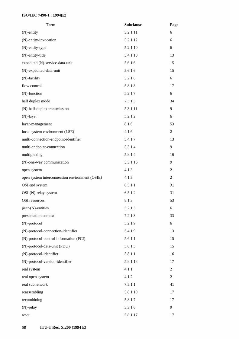
ISO/IEC 7498-1 : 1994(E)
58 ITU-T Rec. X.200 (1994 E)
Term Subclause Page
(N)-entity 5.2.1.11 6
(N)-entity-invocation 5.2.1.12 6
(N)-entity-type 5.2.1.10 6
(N)-entity-title 5.4.1.10 13
expedited (N)-service-data-unit 5.6.1.6 15
(N)-expedited-data-unit 5.6.1.6 15
(N)-facility 5.2.1.6 6
flow control 5.8.1.8 17
(N)-function 5.2.1.7 6
half duplex mode 7.3.1.3 34
(N)-half-duplex transmission 5.3.1.11 9
(N)-layer 5.2.1.2 6
layer-management 8.1.6 53
local system environment (LSE) 4.1.6 2
multi-connection-endpoint-identifier 5.4.1.7 13
multi-endpoint-connection 5.3.1.4 9
multiplexing 5.8.1.4 16
(N)-one-way communication 5.3.1.16 9
open system 4.1.3 2
open system interconnection environment (OSIE) 4.1.5 2
OSI end system 6.5.1.1 31
OSI-(N)-relay system 6.5.1.2 31
OSI resources 8.1.3 53
peer-(N)-entities 5.2.1.3 6
presentation context 7.2.1.3 33
(N)-protocol 5.2.1.9 6
(N)-protocol-connection-identifier 5.4.1.9 13
(N)-protocol-control-information (PCI) 5.6.1.1 15
(N)-protocol-data-unit (PDU) 5.6.1.3 15
(N)-protocol-identifier 5.8.1.1 16
(N)-protocol-version-identifier 5.8.1.18 17
real system 4.1.1 2
real open system 4.1.2 2
real subnetwork 7.5.1.1 41
reassembling 5.8.1.10 17
recombining 5.8.1.7 17
(N)-relay 5.3.1.6 9
reset 5.8.1.17 17
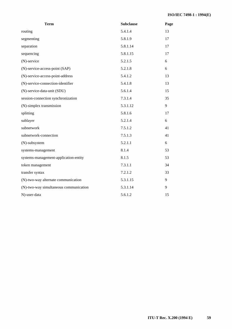
ISO/IEC 7498-1 : 1994(E)
ITU-T Rec. X.200 (1994 E) 59
Term Subclause Page
routing 5.4.1.4 13
segmenting 5.8.1.9 17
separation 5.8.1.14 17
sequencing 5.8.1.15 17
(N)-service 5.2.1.5 6
(N)-service-access-point (SAP) 5.2.1.8 6
(N)-service-access-point-address 5.4.1.2 13
(N)-service-connection-identifier 5.4.1.8 13
(N)-service-data-unit (SDU) 5.6.1.4 15
session-connection synchronization 7.3.1.4 35
(N)-simplex transmission 5.3.1.12 9
splitting 5.8.1.6 17
sublayer 5.2.1.4 6
subnetwork 7.5.1.2 41
subnetwork-connection 7.5.1.3 41
(N)-subsystem 5.2.1.1 6
systems-management 8.1.4 53
systems-management-application-entity 8.1.5 53
token management 7.3.1.1 34
transfer syntax 7.2.1.2 33
(N)-two-way alternate communication 5.3.1.15 9
(N)-two-way simultaneous communication 5.3.1.14 9
N)-user-data 5.6.1.2 15