Embed Size (px)
Citation preview

ISK 71-242 ISK 71-942Betriebsanleitung (Original)ISK 71‑242 + ISK 71‑942 Induktives Sicherheitsschaltgerät De
utsc
h
Seite 3-11
Manuel d’utilisationISK 71‑242 + ISK 71‑942 elais de scurit induction elais de scurit induction de scurit induction induction
Operating ManualISK 71‑242 + ISK 71‑942 Inductive Saet ela Inductive Saet elaela En
glis
hFr
ança
is
Page 13-21
Page 23-31
Manuale di istruzioneISK 71‑242 + ISK 71‑942 Sistema di sicurezza induttivo Ita
liano
Pagina 33-41
GebruiksaanwijzingISK 71‑242 + ISK 71‑942 Inductie Veiligheidsschakelrelais Ne
derla
nds
Pagina 43-51
1110
9
8 7 6 5 4
321
Transmit OpeningStationary Opening
TransmitStationary
Power
ISK 71-24
D-33154 Salzkottenwww.asosafety.com
1110
9
8 7 6 5 4
321
Transmit OpeningStationary Opening
TransmitStationary
Power
ISK 71-942
D-33154 Salzkottenwww.asosafety.com
2
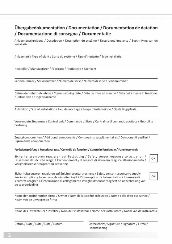
Übergabedokumentation / Documentation / Documentation de datation / Documentazione di consegna / DocumentatieAnlagenbeschreibung / Description / Description du sstème / Descrizione impianto / Beschrijving van de installatie
Anlagenart / Tpe o plant / Sorte du sstème / Tipo d’impianto / Tpe installatie
Hersteller / Manuacturer / Fabricant / Produttore / Fabrikant
Seriennummer / Serial number / Numro de srie / Numero di serie / Seriennummer
Datum der Inbetriebnahme / Commissioning date / Date de mise en marche / Data della messa in unzione / Datum van de ingebruikname
Austellort / Site o installation / Lieu de montage / Luogo d’installazione / Opstellingsplaats
Verwendete Steuerung / Control unit / Commande utilise / Centralina di comando adottata / Gebruikte besturing
Zusatzkomponenten / Additional components / Composants supplmentaires / Componenti ausiliari / Bijkomende componenten
Funktionsprüfung / Functional test / Contrôle de fonction / Controllo funzionale / Functiecontrole
Sicherheitssensoren reagieren au Betätigung / Saet sensor response to actuation / Le senseur de scurit ragit l’actionnement / Il sensore di sicurezza reagisce all’azionamento / Veiligheidssensor reageert op activering
Sicherheitssensoren reagieren au Zuleitungsunterbrechung / Saet sensor response to suppl line interruption / Le senseur de scurit ragit l’interruption de l’alimentation / Il sensore di sicurezza reagisce all’interruzione di collegamento Veiligheidssensor reageert op onderbreking van de toevoerleiding
ok
Name der ausührenden Firma / Owner / Nom de la socit excutrice / Nome della ditta esecutrice / Naam van de uitvoerende firma
Name des Installateurs / Installer / Nom de l’installateur / Nome dell’installatore / Naam van de installateur
Datum / Date / Date / Data / Datum Unterschrift / Signature / Signature / Firma / Handtekening
ok

3
ISK 71-242 + ISK 71-942Induktives Sicherheitsschaltgerät
Technische und betriebsrelevante Änderungen zu den in dieser Dokumentation aufgeführten Produkten und Geräten sind jederzeit auch ohne Vorankündigung vor-behalten.
1. Inhaltsverzeichnis
1. Inhaltsverzeichnis . . . . . . . . . . . . . . . . . . . . . . . 3
2. Allgemeine Sicherheitsbestimmungen und Schutzmaßnahmen . . . . . . . . . . . . . . . . . . . . . . 4
3. Allgemeines und Funktionsbeschreibung . . . . . . . . . . 5
4 . Bestimmungsgemäße Verwendung . . . . . . . . . . . . . 5
5. Sstemkomponenten am Tor . . . . . . . . . . . . . . . . . 6
6. Geräteübersicht . . . . . . . . . . . . . . . . . . . . . . . . 66 .1 Signalanzeigen . . . . . . . . . . . . . . . . . . . . . . . . . . . . 66 .2 Anschlussklemmen . . . . . . . . . . . . . . . . . . . . . . . . . 7
7. Anschluss des Gerätes . . . . . . . . . . . . . . . . . . . . 77.1 Voraussetzungen.1 Voraussetzungen . . . . . . . . . . . . . . . . . . . . . . . . . . 77.2 Versorgungsspannung.2 Versorgungsspannung . . . . . . . . . . . . . . . . . . . . . . . 77 .3 Anschluss eststehender Spulenkern . . . . . . . . . . . . . . . 77 .4 Anschluss eststehende Kontaktleisten . . . . . . . . . . . . . . 77 .5 Anschluss Steuerstromkreise . . . . . . . . . . . . . . . . . . . . 8
8 . Anschließen der mitfahrenden Signalgeber . . . . . . . . . 88 .1 Anschluss am Spulenkern SPK 54 . . . . . . . . . . . . . . . . . 88 .2 .2 Anschluss von mehreren Signalgebern pro Signalgeberkreis . . . 8
9 . Inbetriebnahme und Funktionsprüung . . . . . . . . . . . 8
10. Fehlerdiagnose . . . . . . . . . . . . . . . . . . . . . . . . 9
11 . Außerbetriebnahme und Entsorgung . . . . . . . . . . . 10
12. Technische Daten . . . . . . . . . . . . . . . . . . . . . . 10
13 . EG Konormitätserklärung . . . . . . . . . . . . . . . . . 11De
utsc
h

4
ISK 71-242 + ISK 71-942 Induktives Sicherheitsschaltgerät
2. Allgemeine Sicherheitsbestimmungen und Schutzmaßnahmen • Hersteller und Benutzer der Anlage / Maschine, an der die Schutzeinrichtung verwendet wird, sind daür verantwortlich, alle geltenden Sicherheitsvorschriften und ‑regeln in eigener Verantwortung abzustimmen und einzuhalten.• Die Schutzeinrichtung garantiert in Verbindung mit der übergeordneten Steuerung eine unktionale Sicherheit, nicht aber die Sicherheit der gesamten Anlage / Maschine. Vor dem Einsatz des Gerätes ist deshalb eine Sicherheitsbetrachtung der gesamten Anlage / Maschine nach der Maschinenrichtlinie 2006/42/EG EG oder nach entsprechender Produktnorm notwendig.• Die Bedienungsanleitung muss ständig am Einsatzort der Schutzeinrichtung verügbar sein. Sie ist von jeder Person, die mit der Bedienung, Wartung oder Instandhaltung der Schutzeinrichtung beauftragt wird, gründlich zu lesen und anzuwenden.• Die Installation und Inbetriebnahme der Schutzeinrichtung dar nur durch Fachpersonal erolgen, die mit dieser Betriebsanleitung und den geltenden Vorschriften über Arbeitssicherheit und Unallverhütung vertraut sind. Die Hinweise in dieser Anleitung sind unbedingt zu beachten und einzuhalten. Elektrische Arbeiten düren nur von Elektroachkräften durchgeührt werden.• Sicherheitsvorschriften der Elektrotechnik und der Berusgenossenschaft sind zu beachten.• Bei Arbeiten am Schaltgerät ist dieses spannungsrei zu schalten, au Spannungsreiheit zu prüen und gegen Wiedereinschalten zu sichern .• Werden die potentialreien Kontakte der elaisausgänge mit einer geährlichen Spannung remdgespeist, ist sicherzustellen, dass diese bei Arbeiten an dem Schaltgerät ebenalls abgeschaltet werden.• Das Schaltgerät enthält keine vom Anwender zu wartende Bauteile. Durch eigenmächtige Umbauten bzw. eparaturen am Schaltgerät erlischt jegliche Gewährleistung und Haftung des Herstellers.• Das Schutzsstem ist in geeigneten Zeitabständen von Sachkundigen zu prüen und in jederzeit nach‑ vollziehbarer Weise zu dokumentieren.
Sicherheitshinweise • Das Schaltgerät ermöglicht den Betrieb an 24 V AC/DC. Der Anschluss der Betriebsspannung an die alschen Klemmen kann das Schaltgerät zerstören.• Das Schaltgerät ist in einem Schaltschrank zu montieren.• Nicht in unmittelbarer Nähe von starken Wärmequellen montieren.• Bei kapazitiven und induktiven Verbrauchern ist ür eine ausreichende Schutzbeschaltung zu sorgen.
Das Schaltgerät ist nach ISO 13849-1 „Sicherheitsbezogene Teile von Steuerungen“ für Kat. 3 ausgelegt. Zur Einhaltung der Kat. 3 ist das Schaltgerät redundant, mit zwei sich gegenseitig abfragenden, zwangsgeführten Sicherheitsrelais pro Kanal aufgebaut.
Die Anforderungen der Tornormen EN 12978 „Schutzeinrichtungen für kraftbetätigte Türen und Tore“ und EN 12453 „Nutzungssicherheit kraftbetätigter Tore“ werden ebenfalls erfüllt.
Bei Nichtbeachtung oder vorsätzlichem Missbrauch entfällt die Haftung des Herstellers.
Deut
sch

5
3. Allgemeines und FunktionsbeschreibungDas Seilübertragungssstem ISK löst die Problematik, bewegliche Signalgeber mit einer eststehenden Aus- wertung ohne mechanische Belastung zu verbinden. Die Kommunikation zwischen den beweglichen Signalgebern und der Auswertelektronik beruht hierbei au induktiver Basis. Die Überwachungselektronik induziert hierür eine Frequenz au einen Spulenkern, der in eine geschlossene Leiterschleie eingebunden ist .
Der zweite Spulenkern, an dem die beweglichen Signalgeber angeschlossen sind, empängt diese Frequenz und gibt bei Kabelbruch oder bei Betätigung eines Signalgebers eine entsprechende ückmeldung an die Auswertelektronik.
Das kompakte und montagereundliche Sicherheitsschaltgerät ist ür den Einsatz im Schaltschrank ausgelegt, wo eine 24 V Versorgungsspannung zur Verügung steht. An das Schaltgerät können bis zu vier Sicherheitskontaktleistenkreise angeschlossen werden. Für die Sicher-heitskontaktleisten (SKL) am Torblatt stehen zwei Kanäle (SKL Au‑Bewegung und SKL Zu‑Bewegung), und ür die Sicherheitskontaktleisten am Führungsposten ebenalls zwei Kanäle zur Verügung. Die beweglichen, am Torblatt mitfahrenden Sicherheitskontaktleisten werden durch das Seilübertragungssstem berührungslos und verschleißrei überwacht. Die eststehenden Sicherheitskontaktleisten werden direkt an das Schaltgerät angeschlossen. Das Schaltgerät überwacht diese vier Sicherheitskontaktleistenkreise permanent au Betätigung oder Unter-brechung (Kabelbruch). Bei einer Störung wird dem entsprechenden Sicherheitskontaktleistenkreis einem der zwei Stop‑Beehle zugeordnet (Stop in Au‑ichtung oder Stop in Zu‑ichtung). Um eine uhestromüber-wachung des gesamten Sstems zu ermöglichen, ist in die Endleiste des jeweilige Sicherheitskontaktleisten-kreises ein Abschlusswiderstand integriert. Fließt der Soll‑uhestrom, so sind die Ausgangsrelais angesteuert und die Schaltkontakte geschlossen. Wird das Schaltelement betätigt oder der Signalgeberstromkreis unter-brochen, öffnen die elais‑Schaltkontakte.
Die Schaltzustände der elais und die angelegte Betriebsspannung werden durch LED‘s angezeigt.
4. Bestimmungsgemäße VerwendungDas Schaltgerät ISK 71‑242 (ISK 71‑942) kann seine sicherheitsrelevante Augabe nur erüllen, wenn es bestimmungsgemäß eingesetzt wird.
Das Sicherheitsübertragungssstem ISK 71‑242 (ISK 71‑942) ist ausgelegt ür die Auswertung von eststehenden und mitfahrenden Sicherheitskontaktleisten mit konstantem 8,2KΩ Widerstand.
Ein anderer oder darüber hinausgehender Einsatz ist nicht bestimmungsgemäß. Für Schäden, die aus nicht bestimmungsgemäßen Verwendungen entstehen, übernimmt der Hersteller keine Haftung.
Der Einsatz bei Sonderanwendungen bedar einer Freigabe vom Hersteller.
Deut
sch
6
ISK 71-24
Transmit OpeningStationary Opening
TransmitStationary
Power
ISK 71-242
33 11 10 1 2
2 2 2
5. Systemkomponenten am Tor
2 4 3
1 Tor öffnet
Tor schließt
SKL
AUF
Bew
egun
g
SKL
AUF
Bew
egun
g
SKL
AUF
Bew
egun
g
SKL
ZU B
eweg
ung
SKL
ZU B
eweg
ung
SKL
ZU B
eweg
ung
ISK 71-242 + ISK 71-942 Induktives Sicherheitsschaltgerät
ISK 71-242 ISK 71-942
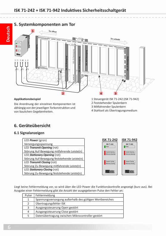
1 Steuergerät ISK 71‑242 (ISK 71‑942)2 Feststehender Spulenkern3 Mitfahrender Spulenkern4 Stahlseil als Übertragungsmedium
ApplikationsbeispielDie Anordnung der einzelnen Komponenten ist abhängig von der jeweiligen Torkonstruktion und von baulichen Gegebenheiten.
6. Geräteübersicht6.1 Signalanzeigen
Deut
sch
LED Power (grün)VersorgungsspannungLED Transmit Opening (rot)Störung Au‑Bewegung mitfahrende Leiste(n)LED Stationary Opening (rot)Störung Au‑Bewegung eststehende Leiste(n)LED Transmit Closing (rot)Störung Zu‑Bewegung mitfahrende Leiste(n)LED Stationary Closing (rot)Störung Zu‑Bewegung eststehende Leiste(n)
Power
Transmit Opening
Stationary Opening
Transmit Closing
Stationary Closing
ISK 71-242Power
Transmit Opening
Stationary Opening
Transmit Closing
Stationary Closing
ISK 71-942
Pulse Fehlermeldung1 Spannungsversorgung außerhalb des gültigen Wertbereiches2 Übertragungsehler ISK3 Ausgangssteuerung Open gestört4 Ausgangssteuerung Close gestört5 Datenübertragung zwischen Mikrocontroller gestört
Liegt keine Fehlermeldung vor, so wird über die LED Power die Funktionskontrolle angezeigt (kurz aus). Bei Ausgabe einer Fehlermeldung gibt die Anzahl der ausgegebenen Pulse den Fehler an:

7
Stationary Op.
Transmit
Stationary Cl.
P o w e r
T r a n s m i t O p e n i n gS t a t i o n a r y O p e n i n g
T r a n s m i t C l o s i n gS t a t i o n a r y C l o s i n g
I S K 7 1 - 9 4 2
Serial No.: 1 0 2 0 1 1 0 0 0 0 0
ISK 71-942 V0.0
Sta
tion
. Op
.
Tr
an
sm
it
Sta
tion
. Cl.
cl
os
in
g
di
re
ct
io
n
op
en
in
g
di
re
ct
io
n
cl
os
in
g
di
re
ct
io
n
op
en
in
g
di
re
ct
io
n
8,2 kOhm
8,2 kOhm
8,2 kOhm
8,2 kOhm
steel rope
transmission coil
fixed
transmission coil
travelling
Te
ch
nic
al d
at
a:
U =
24
V A
C/D
CI =
10
0 m
AP
= 2
,4 W
1110
9
8 7 6 5 4
321
9
8
21
7 6 5 4
1110 3
% %- + 24V AC/DC
1110 3
7 6 5 48
21
9
1110
9
8 7 6 5 4
321
% %- + 24V AC/DC
ISK 71-242 ISK 71-942
Unterseite
ISK 71-942TransmitStationary Op.Stationary Cl. Pin 4, 5Pin 6, 7Pin 8, 9
ISK 71-242 Pin 1, 2 eststehender SpulenkernPin 3, 11 SKL Führungsposten ÖffnenPin 3, 10 SKL Führungsposten Schliessen Pin 4, 5 elais‑Ausgang zur Steuerung Stop ÖffnenPin 6, 7 elais‑Ausgang zur Steuerung Stop SchliessenPin 8, 9 Versorgungsspannung 24 V
7.2 Versorgungsspannung.2 VersorgungsspannungAls Spannungsversorgung ist bei der ISK 71‑242 und der ISK 71‑942 an dem Klemmenpaar 8, 9 24V AC/DC anzuschließen. Die Versorgungsleitung zum Schaltgerät ist mit einer passenden Sicherung zu schützen.
7.3 Anschluss feststehender SpulenkernISK 71-242: An das Klemmenpaar 1, 2 ist der eststehende Spulenkern anzuschließen, wobei die Polarität beliebig ist.ISK 71-942: Der eststehende Spulenkern ist mit dem Steckplatz Transmit zu verbinden. Der Anschluss am Spulenkern erolgt über die mitgelieerten Quetsch‑ verbinder oder durch direktes Anlöten der Leitung an die Stecker.
7.4 Anschluss feststehende KontaktleistenISK 71-242: Die eststehende(n) Sicherheitskontaktleiste(n) (SKL) am Führungsposten ür die Au‑Bewegung wird (werden) an das Klemmen- paar 3, 11 angeschlossen.ISK 71-942: Die eststehende(n) SKL ür die Au‑Bewegung wird (werden) mit dem Steckplatz Stationary Opening verbunden .Bei mehreren SKL werden diese in eihe geschaltet und die Endleiste mit 8,2 kΩ abgeschlossen. ISK 71-242: Die eststehende(n) SKL ür die Zu‑Bewegung wird (werden) an das Klemmenpaar 3, 10 angeschlossen.ISK 71-942: Die eststehende(n) SKL ür die Zu‑Bewegung wird (werden) mit dem Steckplatz Stationary Closing verbunden.Sollte ein Kanal für die feststehenden SKL oder eventuell beide Kanäle nicht genutzt werden, sind die Kanäle mit den mitgelieferten 8,2 kΩ Widerständen zu belegen.
7. Anschluss des Gerätes7.1 Voraussetzungen.1 Voraussetzungen• Die Versorgungsspannung der ISK 71‑242 und der ISK 71‑942 muss den Anorderungen ür Schutzklein‑ spannung (SELV) entsprechen.• Leitungen, die im Freien oder außerhalb vom Schaltschrank verlegt werden, müssen entsprechend geschützt werden.• Die ür das Gerät angegebene Schutzart ist nur dann sichergestellt, wenn die Zuleitungen ordnungsgemäß in die Verschraubungen geklemmt sind.
Deut
sch
6.2 Anschlussklemmen
Stationary Op.
Transmit
Stationary Cl.
Serial No.: 1 0 2 0 1 1 0 0 0 0 0
ISK 71-942 V0.0
8 7 6 5 4
910 11 1 2
3
ISK 71-242 ISK 71-942

8
ISK 71-242 + ISK 71-942 Induktives Sicherheitsschaltgerät
ASO-Signalgeber dürfen nicht parallel geschaltet werden.
Bild 1: Verschaltung am Spulenkern
SKL
ZU-Bewegung
SKL
AUF-Bewegung
OC
9. Inbetriebnahme / FunktionsprüfungNach entsprechendem Anschluss aller elektrischen Verbindungen und Einschalten der Versorgungsspannung, muss die Toranlage au korrekte Funktion überprüft werden. Hierzu sind alle Sicherheitskontaktleisten der eihe nach zu betätigen und die entsprechenden eaktionen des Schaltgerätes zu kontrollieren.
8. Anschließen der Signalgeber8.1 Anschluss am Spulenkern SPK 54 (Bild 1)
8.2 Anschluss von mehreren Signalgebern pro Signalgeberkreis (Bild 2)
An dem Signalgebereingang O bzw . C können ein oder mehrere Signalgeber angeschlossen werden. Hierür werden die einzelnen Signalgeber entsprechend Bild 2 in Serie geschaltet. Maximal können 5 Signalgeber mit einer Gesamtkabellänge von max. 25 m in Serie geschaltet werden. Die Länge eines Signalgebers kann bis zu 25 m betragen. Vor dem Anschließen der in Serie geschalteten Signalgeber ist es empehlenswert, den Widerstandswert der Verschaltung auszumessen.Bei unbetätigter SKL muss der Widerstand 8,2 kΩ ± 500 Ω betragen. Ist die SKL betätigt, dar der Widerstand 500 Ω nicht überschreiten.
Sollte ein Kanal nicht genutzt werden, muss dieser mit einem 8,2 kΩ WiderstandWiderstand belegt werden .
Die mitahrenden Leisten (SKL) werden mit dem mitfahrenden Spulenkern verbunden.Hierzu wird die mitfahrende SKL ZU Bewegung mit dem Anschluss C des mitahrenden Spulenkerns verbunden und die optionale SKL AUF Bewegung mit dem Anschluss O .
Signalgeber 1 Signalgeber 2 Signalgeber „n“
O
C
Bild 2: Verschaltung mehrerer Signalgeber, hier am Beispiel Sicherheitskontaktleiste
Deut
sch
2222
7 6 5 48
1110 3
21
9
7 6 5 48
1110 3
21
9
7.5 Anschluss SteuerstromkreiseAn das Klemmenpaar 4, 5 ist der zu überwachende Steuerstromkreis ür die Au‑Bewegung (Stop‑Au‑Bewegung) und an das Klemmenpaar 6, 7 der entsprechende Steuerstromkreis ür die Zu‑Bewegung (Stop‑Zu‑Bewegung) anzuschließen. Die Steuerstromkreise sind abhängig vom Nennstrom mit einer entsprechenden Sicherung zu schützen, oder der Nennstrom au den Steuerstromkreisen muss durch andere Maßnahmen au den maximalen Wert begrenzt werden.

9
10. FehlerdiagnoseBei korrekter Verdrahtung und Anlegen der Versorgungsspannung dar nur die grüne LED leuchten. Bei Aufleuchten einer der roten LED‘s ist ein Fehler im Sstem vorhanden, der sich mit Hile der LED eingrenzen lässt.
LED Fehler FehlerbeseitigungLED‘s leuchten nicht
Versorgungsspannung ehlt, zu gering oder alsch angeschlossen
Anschlüsse und Versorgungsspannung überprüen:‑ 24 V AC/DC an Klemmen 8 9Toleranzbereich: ±10%
einzelne rote LED leuchtet
Kontaktleiste(n) nicht angeschlossen, ehlerhaft angeschlossen oder deekt
‑ Anschlüsse der entsprechenden Kontaktleiste überprüen (abgequetschte Zuleitungen, brüchige Zuleitungen etc.)
‑ Sicherheitskontaktleiste(n) überprüen*
Ein Kontaktleisten‑Anschluss wird nicht benutzt
Nicht benutzte Kontaktleisten‑Anschlüsse dauer-haft mit einem der mitgelieerten 8,2 kΩ‑Wider-stände überbrücken
beide roten Transmit LED‘s leuchten
Übertragungsstrecke ist gestört oder ehlerhaft montiert
‑ mech. Montageanleitung beachten (ISK Sicher-heitsübertragungsstem)
‑ Übertragungskerne au Verschleiß überprüen. ‑ Seilkreis überprüen; hier ist darau zu achten, dass beide Übertragungskerne sich innerhalb des Seilkreis befinden‑ Kontaktstellen Seil / Torkörper überprüen.‑ Versorgungsspannung überprüen**
Kontaktleiste(n) nicht angeschlossen, ehlerhaft angeschlossen oder deekt
‑ Anschlüsse der entsprechenden Kontaktleiste überprüen (abgequetschte Zuleitungen, brüchige Zuleitungen etc.)
‑ Sicherheitskontaktleiste(n) überprüen*
* Liegt der Fehler nicht in der Verdrahtung, kann die Funktion der Elektronik durch Belegung aller SKL‑ Eingänge an der ISK 71‑242 (ISK 71‑942) Auswertelektronik (Klemmen 3, 10 und Klemmen 3, 11) und am mitfahrenden Spulenkern (Anschlüsse O und C) mit jeweils einem 8,2 kΩ Widerstand überprüft werden. Arbeitet danach die Elektronik einwandrei, müssen die Sicherheitskontaktleisten mit einem Wider‑ standsmessgerät überprüft werden. Hierür muss die jeweilige Verbindung der SKL zur Auswertelektronik oder zum mitfahrenden Spulenkern augetrennt und mit einem Widerstandsmessgerät verbunden werden .
Bei unbetätigter Sicherheitskontaktleiste muss der Widerstand 8,2 kΩ ±500 Ω betragen. Ist die Sicher-heitskontaktleiste betätigt, dar der Widerstand 500 Ω nicht überschreiten.
** Sollten die beiden LED’s ür die mitfahrenden SKL (Transmit Opening und Transmit Closing) leuchten, ist ein Fehler im induktiven Übertragungssstem vorhanden. Die häufigsten Fehlerquellen hierür sind schlechte Verbindungen an den Spulenkernen, nicht ordnungsgemäß installierte Seilsstemkomponenten (siehe Montageanleitung ISK‑Sicherheitsübertragungssstem) oder eine unzulässig niedrige Versorgungs-spannung .
Die Seilschleie dar einen maximalen Widerstandswert von 3 Ω haben. Der Widerstandswert kann durch Lösen des Stahlseiles von der Erdungsklemme und anschließendem Messen zwischen Stahlseilende und Erdungsklemme ermittelt werden.
Deut
sch

10
ISK 71-242 + ISK 71-942 Induktives Sicherheitsschaltgerät
11. Außerbetriebnahme und EntsorgungDie von ASO hergestellten Produkte sind ausschließlich ür den gewerblichen Gebrauch (B2B) vorgesehen. Nach Nutzungsbeendigung sind die Produkte gemäß allen örtlichen, regionalen und nationalen Vorschriften zu entsorgen. ASO nimmt die Produkte auch gern zurück und entsorgt diese ordnungsgemäß.
12. Technische DatenVersorgungsspannung UE 24 V AC/DC ±10% IE = 85 mA; Imax = 180mA (100ms)
Anschlusswiderstand Sicherheitskontaktleisten Nominalwert nom = 8,2 kΩ oberer Schaltwert AO > 20 kΩ unterer Schaltwert AU < 2,5 kΩ
Relais Stufen Nennstrom DC 3 A 30 V DC Nennstrom AC 3 A 30 V AC Mech. Lebensdauer >106 Betätigungen
Schaltzeiten Sicherheitsrelais eaktionszeit < 10 ms (eststehende SKL) < 30 ms (ISK) Freischaltzeit 500 ms
MontageStecksockel zur 35 mm DIN‑Schnappschienenmontage
Gehäuse 11 pol. DIN Stecksockelgehäuse mit Stecksockel ür 35 mm MontageschieneAbmessungen: (HxBxT) Gehäuse 82 x 38 x 84 mm Gehäuse incl. Stecksockel 82 x 38 x 110 mm
Schutzart IP20
Gewicht 225 g
Temperaturbereich ‑25°C bis +55°C
Querschnitt Anschlussleitungenein‑, oder eindrähtige Leitung 0,75‑1,5 mm2
Zulassungen DIN EN ISO 13849‑1:2008 Kategorie 3 PL e MTTFd 170 Jahre, DC 91% Elektronik MTTFd 1616 Jahre, DC 99 % Elektromechanik B10d 1000000 MTTFd 190 Jahre (Nop 52560) Sicherheitseinrichtung nach DIN EN 12978
Alle an das Schaltgerät angeschlossenen Spannungen müssen sicher getrennte Spannungen sein!
Deut
sch
Prüfbericht Nr.:12 205 399386-000
Zertifikat Nr.:44 780 12 399386
EG Baumuster Nr.: 44 205 12 399386
1110
9
8 7 6 5 4
321
Transmit OpeningStationary Opening
TransmitStationary
Power
ISK 71-942
38
82
84
26
D-33154 Salzkottenwww.asosafety.com
1110
9
8 7 6 5 4
321
Transmit OpeningStationary Opening
TransmitStationary
Power
ISK 71-242
38
82
84
26
D-33154 Salzkottenwww.asosafety.com
ISK 71-242
ISK 71-942

11
13. EG Konformitätserklärung
Hiermit erklären wir, dass die nacholgend bezeichneten Produkte der Baureihe:
ISK 71-242 (Artikelnummer 1204‑0100, Format Seriennummer mmnnnnn)ISK 71-942 (Artikelnummer 1204‑0110, Format Seriennummer mmnnnnn)
Induktive Übertragungsvorrichtung mit Sicherheitsschaltsstem zur Kombination mit Schaltleisten zur Vermeidung von Geahren an Quetsch‑ und Scherstellen bei Tor‑ sstemen augrund ihrer Konzipierung und Bauart sowie in der von uns in Verkehr gebrachten Ausührung, den einschlägigen grundlegenden Sicherheits‑ und Gesund-heitsanorderungen der nacholgenden EG‑ichtlinien und Normen entspricht:
EG - Maschinenrichtlinie 2006/42/EGEN ISO 13849‑1:2008EN ISO 13849‑2:2008EN 61000‑6‑2:2005EN 61000‑6‑3:2007
EG - BaumusterprüfungNotified Bod 0044TÜV NOD CET GmbHLangemarckstraße 20D‑45141 EssenEG Baumuster Nr.: 44 205 12 399386
Diese Konormitätserklärung entbindet den Konstrukteur/Hersteller der Maschine nicht von seiner Pflicht, die Konormität der gesamten Maschine, an der dieses Produkt angebracht wird, entsprechend der EG‑ichtlinie sicherzustellen.
Hersteller und Dokumentenbevollmächtigter:ASO, Antriebs‑ und Steuerungstechnik GmbH,Am Grarock 8, D‑33154 Salzkotten
Salzkotten, den XX.XX.2012
Helmut Friedrich(Geschäftsührer und Dokumentenbevollmächtigter)
Deut
sch

12

13
Engl
ish
ISK 71-242 + ISK 71-942 Inductive Safety Relay Inductive Safety RelayRelay
We reserve the right to make technical and operationally relevant changes to the products and devices described in this documentation at any time and without prior notice.
1. Contents
1. Contents . . . . . . . . . . . . . . . . . . . . . . . . . . . 13
2. General saet regulations and protective measures . . 14
3. General and Function . . . . . . . . . . . . . . . . . . . . 15
4 . Proper use . . . . . . . . . . . . . . . . . . . . . . . . . . 15
5. Sstem components fitted to the gate . . . . . . . . . . . 16
6. Device overview . . . . . . . . . . . . . . . . . . . . . . . 166 .1 Signal Indicators . . . . . . . . . . . . . . . . . . . . . . . . . . . 166 .2 Connection terminals . . . . . . . . . . . . . . . . . . . . . . . . 17
7. Connecting the device . . . . . . . . . . . . . . . . . . . 177.1 Prerequisites Prerequisites . . . . . . . . . . . . . . . . . . . . . . . . . . . . . 1777.2 Suppl voltage Suppl voltage . . . . . . . . . . . . . . . . . . . . . . . . . . . . 1777 .3 Connecting the stationar coil core . . . . . . . . . . . . . . . . 177 .4 Connecting the stationar contact edges . . . . . . . . . . . . . 18
8 . Connecting the travelling sensors . . . . . . . . . . . . . 188 .1 Connecting to the coil core SPK 54 . . . . . . . . . . . . . . . . 188.2 Connecting multiple sensors per sensor circuit Connecting multiple sensors per sensor circuit . . . . . . . . . . 18
9 . Commissioning and unctional test . . . . . . . . . . . . . 18
10. Error diagnosis . . . . . . . . . . . . . . . . . . . . . . . . 19
11 . Taking out o service and disposal . . . . . . . . . . . . . 20
12. Technical specifications . . . . . . . . . . . . . . . . . . . 20
13 . EC declaration o conormit . . . . . . . . . . . . . . . . 21

14
Engl
ish
2. General safety regulations and protective measures • The manuacturer and users o the plant / machine on which the protection is being used are responsible
or implementing and ollowing all applicable saet regulations and rules.• When used in conjunction with the higher‑order controller, the protection guarantees unctional saet,
but not the saet o the entire plant / machine. The saet o the entire plant / machine must, thereore, be assessed in accordance with machiner directive 2006/42/EG or appropriate product norm beore using the device.
• The operating instructions must alwas be available at the place o installation o the protection. The must be read thoroughl and observed b all persons involved in the operation, maintenance and
servicing o the protection.• The protection must onl be installed and commissioned b proessionals amiliar with these opera-
ting instructions and the applicable operational saet and accident prevention regulations. All o the instructions provided in these operating instructions must be observed and ollowed.
All electrical work must onl be perormed b skilled electricians.• All relevant electrical engineering and Emploer's Liabilit Insurance Association saet regulations must
be observed.• During work on the switching unit, it is to be switched to zero potential, checked to ensure that it is at
zero potential and protected against being restarted.• I the potential‑ree contacts o the rela outputs are supplied externall with a dangerous voltage, make
certain that these outputs are also switched off during work on the switching unit.• The switching unit does not contain an components that require servicing b the user. Unauthorised
conversions and repairs made to the switching unit will void all guarantees and the manuacturer’s liabilit.
• The protection sstem is to be proessionall inspected at appropriate intervals and be documented in such a wa that it is comprehensible at all times.
Safety advice • The switching unit enables operation at 230 V as well as with 24 V AC/DC. Connecting the operating voltage
to the wrong terminals can destro the switching unit.• The switching unit is to be installed in a switching cabinet.• Do not install in the immediate vicinit o strong sources o heat.• For capacitive and inductive loads, ensure adequate protective circuits.
The switching unit complies with EN ISO 13849-1 "Safety-related parts of control systems", Cat. 3. To meet Cat. 3 requirements, the switching unit has a redundant structure with two, two-way polling, forcibly actuated safety relays per channel.
The requirements of EN 12978 "Safety devices for power operated doors and gates" and EN 12453 "Safety in use of power operated gates" are also fulfilled.
The manufacturer assumes no liability in the event of non-observance or intentional abuse.
ISK 71-242 + ISK 71-942 Inductive Safety Relay Inductive Safety RelayRelay
15
Engl
ish
3. General and FunctionThe ISK signal transmission sstem solves the problem o connecting moveable sensors to a stationar evalua-tion sstem without mechanical stress. Communication between the moveable sensors and the electronic evaluation sstem is based on induction. To achieve this, the monitoring electronics induce a requenc on a coil core, which is integrated in a closed conductor loop.
The second coil core, to which the moveable sensors are connected, receives this requenc and sends cor-responding eedback to the electronic evaluation sstem in the event o cable break or actuation o a sensor.
The compact and eas‑to‑install saet rela is designed or outdoor use and can be operated with 230 V mains voltage or 24 V AC/DC. Up to our saet contact edge circuits can be connected to the switching unit. Two channels (SCE opening movement and SCE closing movement) are available or the saet contact edges (SCE) on the gate lea; two channels are also available or the saet contact edges on the leading pillar. The signal transmission sstem monitors the travelling saet contact edges on the gate lea without contact and without abrasion. The stationar saet contact edges are connected directl to the switching unit. The switching unit continuousl monitors these our saet contact edge circuits or actuation or interruption (cable break). In the event o a ault, one o the two stop commands (stop in the opening direction or stop in the closing direction) is issued to the respective saet contact edge circuit. A terminating resistor is integra-ted into the end edge o the relevant saet contact edge circuit in order to enable the standb current o the entire sstem to be monitored. I the specified standb current is flowing, the output relas are activated and the switching contacts are closed. I the switching element is actuated or the sensor circuit is interrupted, the rela switching contacts open.
The switching states o the relas and the applied operating voltage are indicated b LEDs.
4. Proper useThe ISK 71‑242 (ISK 71‑942) switching unit can onl ulfil its saet‑related task i used properl.
The ISK 71‑242 (ISK 71‑942) saet transmission sstem is designed or evaluating stationar and travelling saet contact edges with constant 8.2 kΩ resistance.
An uses above and beond these uses constitute improper use. The manuacturer assumes no liabilit or damages arising rom improper use.
The device ma onl be used in special applications with the manuacturer’s express consent.

16
ISK 71-24
Transmit OpeningStationary Opening
TransmitStationary
Power
ISK 71-242
33 11 10 1 2
2 2 2
Engl
ish
ISK 71-242 + ISK 71-942 Inductive Safety Relay Inductive Safety RelayRelay
ISK 71-242 ISK 71-942
6. Device overview6.1 Signal Indicators
LED Power (green)Suppl voltageLED Transmit Opening (red)Fault, opening movement ‑ travelling edge(s)LED Stationary Opening (red)Fault, opening movement stationar edge(s)LED Transmit Closing (red)Fault, closing movement ‑ travelling edge(s)LED Stationary Closing (red)Fault, closing movement ‑ stationar edge(s)
Power
Transmit Opening
Stationary Opening
Transmit Closing
Stationary Closing
ISK 71-242Power
Transmit Opening
Stationary Opening
Transmit Closing
Stationary Closing
ISK 71-942
Pulse Error message1 Voltage suppl outside o the valid value range2 ISK transmission error3 Output control Open ault4 Output control Close ault5 Data transmission with microcontroller ault
I no error is present, then LED Power shows the unction control (briefl off). During the output o an error message, the number o output pulses indicates the error:
5. System components fitted to the gate
2 4 3
Gate opens
Gate closes
SCE
OPE
N m
ovem
ent
SCE
OPE
N m
ovem
ent
SCE
OPE
N m
ovem
ent
SCE
CLO
SE m
ovem
ent
SCE
CLO
SE m
ovem
ent
SCE
CLO
SE m
ovem
ent
1 ISK 71‑242 (ISK 71‑942) control device2 Stationar coil core3 Travelling coil core4 Steel cable acting as transmission medium
Example of useThe actual arrangement o the individual components depends on the design o the gate in question and the conditions at the installation site.
1

17
7. Connecting the device7.1 Prerequisites.1 PrerequisitesPrerequisites• The suppl voltage used or the ISK 71‑242 and the ISK 71‑942 must compl with the requirements or saet low voltage (SELV).• Cables installed outdoors or outside o the switching cabinet must be protected appropriatel.• The protection class specified or this device is onl ensured i the suppl lines have been properl clamped to the screw connections.
Engl
ish
Stationary Op.
Transmit
Stationary Cl.
P o w e r
T r a n s m i t O p e n i n gS t a t i o n a r y O p e n i n g
T r a n s m i t C l o s i n gS t a t i o n a r y C l o s i n g
I S K 7 1 - 9 4 2
Serial No.: 1 0 2 0 1 1 0 0 0 0 0
ISK 71-942 V0.0
Sta
tion
. Op
.
Tr
an
sm
it
Sta
tion
. Cl.
cl
os
in
g
di
re
ct
io
n
op
en
in
g
di
re
ct
io
n
cl
os
in
g
di
re
ct
io
n
op
en
in
g
di
re
ct
io
n
8,2 kOhm
8,2 kOhm
8,2 kOhm
8,2 kOhm
steel rope
transmission coil
fixed
transmission coil
travelling
Te
ch
nic
al d
at
a:
U =
24
V A
C/D
CI =
10
0 m
AP
= 2
,4 W
1110
9
8 7 6 5 4
321
9
8
21
7 6 5 4
1110 3
% %- + 24V AC/DC
1110 3
7 6 5 48
21
9
1110
9
8 7 6 5 4
321
% %- + 24V AC/DC
ISK 71-242 ISK 71-942
Bottom
ISK 71-942TransmitStationary Op.Stationary Cl. Pin 4, 5Pin 6, 7Pin 8, 9
ISK 71-242 Pin 1, 2 stationar coil corePin 3, 11 SCE ‑ leading pillar openingPin 3, 10 SCE ‑ leading pillar closing Pin 4, 5 rela output or controller ‑ stop openingPin 6, 7 rela output or controller ‑ stop closingPin 8, 9 suppl voltage 24 V
7.2 Supply voltage.2 Supply voltageSupply voltageWith the ISK 71‑242 and ISK 71‑942, 24 V AC/DC is to be connected to terminal pair 8, 9 as voltage suppl. The suppl line to the switching unit must be protected with an appropriate use.
7.3 Connecting the stationary coil coreISK 71-242: Connect the stationar coil core to terminal pair 1, 2; no special attention is required or polarit.ISK 71-942: The stationar coil core is to be connected to the Transmit slot. The cable or the coil core is connected using the supplied crimp connec-tors or b directl soldering the wire to the connectors.
7.4 Connecting the stationary contact edgesISK 71-242: The stationar saet contact edge(s) (SCE) on the leading pillar or the opening movement is (are) connected to terminal pair 3, 11 .ISK 71-942: The stationar SCE(s) or the opening movement is (are) connected to the Stationary Opening slot .I several SCEs are being used, the must be connected in series and the end edge must be terminated using an 8.2 kΩ resistor. ISK 71-242: The stationar SCE(s) or the closing movement is (are) con-nected to terminal pair 3, 10 .ISK 71-942: The stationar SCE(s) or the closing movement is (are) connected to the Stationary Closing slot.If one or both channels for the stationary SCE are not used, the sup-plied 8.2 kΩ resistors are to be connected to the respective channels.
6.2 Connection terminals
Stationary Op.
Transmit
Stationary Cl.
Serial No.: 1 0 2 0 1 1 0 0 0 0 0
ISK 71-942 V0.0
8 7 6 5 4
910 11 1 2
3
ISK 71-242 ISK 71-942

18
Engl
ish
ISK 71-242 + ISK 71-942 Inductive Safety Relay Inductive Safety RelayRelay
7 6 5 48
1110 3
21
9
7 6 5 48
1110 3
21
9
7.5 Connecting the control circuitsThe control circuit to be monitored or the opening movement (stop‑opening movement) is to be connected to terminal pair 4, 5 ; or the closing movement (stop‑closing movement), the appropriate control circuit is to be connected to terminal pair 6, 7. The control circuits areThe control circuits are dependent on the rated current to protect with an appropriate use or the rated current to the control circuits must be limited b other measures to the maximum value.
ASO sensors must not be connected in parallel.
Figure 1: Connection at the coil core
SCE
CLOSING
movement
SCE
OPENING
movement
OC
8. Connecting the sensors8.1 Connecting to the coil core SPK 54 (figure 1)
9.2 Connecting multiple sensors per sensor circuit (figure 2)One or more sensors can be connected to sensor input O or C. For this purpose, the individual sensors are connected in series according to figure 2. Up to five sensors ma be connected in series, whereb the total cable length must not exceed 25 m.The length o one sensor ma be up to 25 m. Beore connecting the sensors that are connected in series, it is recommended that the resistance value o the arrangement be measured.The resistance must be 8.2 kΩ ± 500 Ω when the SCE is inactive and must not exceed 500 Ω when it is active.
I a channel is not used, it must be connected to an 8,2 kΩ resistor.resistor.
The travelling edges (SCE) are connected to the tra-velling coil core.For this purpose, the travelling SCE CLOSING movement is connected to connection C o the travelling coil core and the optional SCE OPENING movement is connected to connection O .
9. Commissioning / functional testThe gate sstem must be tested or proper unction after all o the electrical connections have been established and the suppl voltage has been turned on. To do this, activate each o the saet contact edges one after another and check the corresponding reactions o the switching unit.
Figure 2: Wiring of multiple sensors; in this example: safety contact edge
Sensor 1 Sensor 2 Sensor „n“
O
C2222

19
Engl
ish
10. Error diagnosisOnl the green LED ma illuminate i the suppl voltage has been correctl connected. I one o the red LEDs illuminate, there is an error in the sstem which can be pinpointed with the aid o the LED.
LED Error Error correctionLEDs are not illuminated
The suppl voltage is missing, too low or has been connected incor-rectl
Check connections and suppl voltage:‑ 24 V AC/DC at terminals 8 9Tolerance range: ±10%
A single red LED is illuminated
Contact edge(s) not connected, connected incorrectl or ault
- Check the connections o the corresponding contact edge (squeezed or brittle suppl lines, etc.)
‑ Check saet contact edge(s)*
One o the contact edge connections is not being used
An contact edge connections that are not being used must be permanentl bridged using one o the supplied 8.2 kΩ resistors
Both o the red Transmit LEDs are illuminated
The transmission line is ault or has been installed incorrectl
‑ Observe the mech. assembl instructions (ISK saet transmission sstem)
‑ Check transmission coil cores or abrasion. ‑ Check cable loop; make certain that both transmission coil cores are in the cable loop
‑ Check cable / gate lea contact points.‑ Check suppl voltage**
Contact edge(s) not connected, connected incorrectl or ault
- Check the connections o the corresponding contact edge (squeezed or brittle suppl lines, etc.)
‑ Check saet contact edge(s)*
* I the error is not in the wiring, the unction o the electronics can be tested b connecting an 8.2 kΩ resistor to all SCE inputs on the ISK 71‑242 (ISK 71‑942) electronic evaluation sstem (terminals 3, 10 and terminals 3, 11) and to the travelling coil core (connections O and C). I the electronics work perectl after perorming the test, the saet contact edges must be checked using an ohmmeter. To do this, the respective connection on the SCE or the electronic evaluation sstem or or the travelling coil core must be disconnected and connected to an ohmmeter.
The resistance must be 8.2 kΩ ±500 Ω when the saet contact edge is inactive and must not exceed 500 Ω when it is active.
** I both o the LEDs or the travelling SCEs (Transmit Opening and Transmit Closing) illuminate, there is an error in the inductive signal transmission sstem. The most requent causes o these errors are bad coil core connections, incorrectl installed cable sstem components (see IKS saet transmission sstem assembl instructions) or an impermissibl low suppl voltage.
The maximum resistance value o the cable loop must not exceed 3 Ω . The resistance value can be measured b disconnecting the steel cable rom the ground terminal and then measuring the resistance between the end o the steel cable and ground terminal.

20
Engl
ish
ISK 71-242 + ISK 71-942 Inductive Safety Relay Inductive Safety RelayRelay
12. Technical specificationsSupply voltage UE 24 V AC/DC ±10% IE = 85 mA; Imax = 180mA (100ms)
Terminal resistance of the SCEs nominal value nom = 8,2 kΩ upper switching point AO > 20 kΩ lower switching point AU < 2,5 kΩ
Relay stages Nominal current DC 3 A 30 V DC Nominal current AC 3 A 30 V AC Mechanical lie‑time >106 actuations
Safety relay switching times esponse time < 10 ms (stationar SCE) < 30 ms (ISK) Turn‑off time 500 ms
AssemblyPlug base or 35 mm DIN snap‑on rail mounting
Housing 11‑pin DIN plug‑base housing with plug base or 35 mm mounting rail (DIN rail)Dimensions: (HxWxD) Housing 82 x 38 x 84 mm Housing incl. plug base 82 x 38 x 110 mm
Protection class IP20
Weight 225 g
Temperature range ‑25°C to +55°C
Connection cable cross-sectionsingle‑ or fine‑stranded cable 0,75‑1,5 mm2
Certifications DIN EN ISO 13849‑1:2008 Categor 3 PL e MTTFd 170 ears, DC 91% Elektronik MTTFd 1616 ears, DC 99 % Elektromechanik B10d 1000000 MTTFd 190 ears (Nop 52560) Saet device acc. to DIN EN 12978
All voltages connected to the switching unit must be safely isolated!
Prüfbericht Nr.:12 205 399386-000
Zertifikat Nr.:44 780 12 399386
EG Baumuster Nr.: 44 205 12 399386
1110
9
8 7 6 5 4
321
Transmit OpeningStationary Opening
TransmitStationary
Power
ISK 71-942
38
82
84
26
D-33154 Salzkottenwww.asosafety.com
1110
9
8 7 6 5 4
321
Transmit OpeningStationary Opening
TransmitStationary
Power
ISK 71-242
38
82
84
26
D-33154 Salzkottenwww.asosafety.com
ISK 71-242
ISK 71-942
11. Taking out of service and disposalThe products manuactured b ASO are intended solel or commercial use (B2B). At the end o use, the products are to be disposed o according to all local, regional and national regulations. Products can also be returned to ASO, which will then dispose o them properl.

21
Engl
ish
13. EC declaration of conformity
We hereb declare that the ollowing product:
ISK 71-242 (part no. 1204‑0100, serial number ormat mmnnnnn)ISK 71-942 (part no. 1204‑0110, serial number ormat mmnnnnn)
Saet rela to be used in combination with saet edges, saet contact mats and saet bumpers or preventing dangers at locations where there is a risk o crushing and cutting satisfies the relevant essential health and saet requirements o the EC directives and standards listed below on account o its design and construction, as does the version brought to market b us:
EC - machinery directive 2006/42/ECEN ISO 13849‑1:2008EN ISO 13849‑2:2008EN 61000‑6‑2:2005EN 61000‑6‑3:2007
EC - type approvalNotified Bod 0044TÜV NOD CET GmbHLangemarckstraße 20D‑45141 EssenEC tpe‑examination no.: 44 205 12 399386
This declaration o conormit does not relieve the designer/manuacturer o the machine rom his obligation to ensure that the conormit o the entire machine to which this product is attached satisfies the corresponding EC directive.
Manufacturer and Authorised Signatory:ASO, Antriebs‑ und Steuerungstechnik GmbH,Am Grarock 8, D‑33154 Salzkotten / German
Salzkotten, XX.XX.2012
Helmut Friedrich(General Manager and Authorised Signator)

22

23
Fran
çais
ISK 71-242 + ISK 71-942 Relais de sécurité inductif
Des modifications techniques et importantes pour le fonctionnement des produits et appareils décrits dans cette documentation sont possibles à tout moment et sans préavis.
1. Table des matières
1. Table des matières . . . . . . . . . . . . . . . . . . . . . 23
2. Prescriptions gnrales de scurit et mesures de protection . . . . . . . . . . . . . . . . . . . . . . . . 24
3. Gnralits et Fonctionnement . . . . . . . . . . . . . . 25
4 . Utilisation conorme . . . . . . . . . . . . . . . . . . . . 25
5. Composants du sstème sur le portail . . . . . . . . . . . 26
6. Vue d'ensemble de l'appareil . . . . . . . . . . . . . . . 266 .1 Indicateurs . . . . . . . . . . . . . . . . . . . . . . . . . . . . . . 266 .2 Bornes de connexion . . . . . . . . . . . . . . . . . . . . . . . . 27
7. accordement de l'appareil . . . . . . . . . . . . . . . . 277.1 Conditions Conditions . . . . . . . . . . . . . . . . . . . . . . . . . . . . . . 2777.2 Alimentation Alimentation . . . . . . . . . . . . . . . . . . . . . . . . . . . . . 2777 .3 accordement du noau de bobine stationnaire . . . . . . . . . 277 .4 accordement des barres palpeuses stationnaires . . . . . . . . 277 .5 accordement des circuits de contrôle . . . . . . . . . . . . . . 28
8 . accordement des metteurs de signaux mobiles . . . . 288 .1 accordement au noau de bobine SPK 54 . . . . . . . . . . . . 288.2 accordement de plusieurs metteurs de signaux par accordement de plusieurs mett eurs de signaux paraccordement de plusieurs metteurs de signaux par circuit de signal . . . . . . . . . . . . . . . . . . . . . . . . . . . 28
9 . Mise en service et test des onctions . . . . . . . . . . . . 28
10. Diagnostic d'erreurs . . . . . . . . . . . . . . . . . . . . . 29
11 . Mise hors‑service et limination . . . . . . . . . . . . . . 30
12. Donnes techniques . . . . . . . . . . . . . . . . . . . . 30
13 . Dclaration de conormit CE . . . . . . . . . . . . . . . 31
24
Fran
çais
ISK 71-242 + ISK 71-942 Relais de sécurité inductif
2. Prescriptions générales de sécurité et mesures de protection • Le abricant et l'utilisateur du sstème / de la machine sur lequel est plac le dispositi deprotection, ont
la responsabilit d'appliquer et de suivre toutes les directives et règles de scurit en vigueur.• Le dispositi de protection associ une commande approprie garantit la scurit onctionnelle, mais
pas celle de l'ensemble du sstème / de la machine. Avant l'emploi de l'appareil, une valuation de la scurit de l'ensemble du sstème / de la machine est donc indispensable conormment la directive sur les machines 2006/42/EG ou la norme de produit correspondante.
• Le mode d'emploi doit toujours être disponible sur le lieu d'utilisation du dispositi de protection. Il doit être minutieusement lu et appliqu par toute personne charge de l'emploi, de l'entretien et de
la maintenance du dispositi de protection.• Seul le personnel spcialis connaissant ce mode d'emploi et les prescriptions en vigueur en matière
de scurit de travail et de prvention des accidents a le droit d'effectuer l'installation et la mise en service du dispositi de protection. Les indications de ce manuel doivent imprativement être suivies et respectes.
Les travaux lectriques doivent être effectus uniquement par des lectriciens proessionnels.• Les prescriptions de scurit du secteur de l'lectrotechnique et des associations proessionnelles
doivent être respectes.• Lors de travaux sur le relais de scurit, il aut couper la tension, vrifier l'absence de tension et le protger
contre tout renclenchement.• Si une tension dangereuse alimente les contacts libres de potentiel des sorties relais, il aut s'assurer que
cette tension est galement teinte lors des travaux sur le relais de scurit.• Le relais de scurit ne contient pas d'lments ncessitant un entretien par l'utilisateur. Des transor‑
mations ou rparations du relais de scurit par soi‑même entraînent la perte de toute garantie et de toute responsabilit du abricant.
• Le sstème de protection doit être examin par des spcialistes et document de açon toujours comp-rhensible intervalles adapts.
Consignes de sécurité • Le relais de scurit peut être utilis sous 230 V comme sous 24 V CA/CC. Le raccordement de la tension
de service aux mauvaises bornes peut dtruire le relais de scurit.• Le relais de scurit doit être mont dans une armoire de contrôle.• Ne pas l'installer proximit immdiate de ortes sources de chaleur.• En cas de consommateurs capacitis et inductis, garantir un circuit de protection suffisant.
Le relais de sécurité est conçu pour la catégorie 3 de la norme EN ISO 13849-1, « Parties des systèmes de commande relatives à la sécurité ». Afin de respecter les exigences requises pour la catégorie 3, le relais de sécurité est redondant et emploie deux relais forcés qui s'interrogent mutuellement par canal.
Les exigences des normes EN 12978 « Dispositifs de sécurité pour portes et portails motorisés » et EN 12453 « Sécurité pour l'usage de portes ou portails motorisés » sont également remplies. Le fabricant n'est pas responsable en cas de non-respect ou d'utilisation non conforme intentionnelle.

25
Fran
çais
3. Généralités et FonctionnementLe sstème de transmission par câble ISK sert relier des metteurs de signaux mobiles avec une unit d'valuation stationnaire sans contrainte mcanique. La communication entre les metteurs de signaux mo-biles et le sstème lectronique d'valuation est inductive. Le sstème lectronique de surveillance induit pour cela une rquence sur un noau de bobine intgr dans une boucle de transmission erme.
Le deuxième noau de bobine, auquel les metteurs de signaux mobiles sont raccords, reçoit cette rquence et, en cas de rupture de câble ou d'actionnement d'un metteur de signaux, il envoie un message de eed‑back correspondant au sstème lectronique d'valuation.
Le relais de scurit compact et acile monter est conçu pour l'emploi en extrieur et peut être utilis sous la tension rseau de 230 V ou avec une alimentation de 24 V CA/CC. Il est possible de raccorder jusqu' 4 circuits de barres palpeuses au relais de scurit. Deux canaux sont disponibles pour les barres palpeuses (SKL) montes sur le vantail de porte (mouvement d'ouverture et mouvement de ermeture) et deux autres canaux pour les barres palpeuses montes sur le poteau de gui-dage. Les barres palpeuses mobiles embarques sur le vantail de porte sont surveilles sans contact et sans usure par le biais du sstème de transmission par câble. Les barres palpeuses stationnaires sont raccordes directement au relais de scurit. Le relais de scurit contrôle constamment l'actionnement ou l'interruption (rupture de câble) de ces quatre circuits de barres palpeuses. En cas d'incident, un des deux ordres d'arrêt (arrêt d'ouverture ou arrêt de er-meture) est attribu au circuit de barres palpeuses correspondant. Afin de permettre un contrôle du courant de repos de tout le sstème, une rsistance terminale est intgre dans la barre palpeuse de fin de parcours du circuit de barres palpeuses concern. Lorsque le courant de repos thorique circule, les relais de sortie sont activs et les contacts de commutation sont erms. Si l'lment de commutation est actionn ou si le circuit de signal est interrompu, les contacts de commutation des relais s'ouvrent.
Les tats de commutation des relais et la tension de service sont indiqus par des LED.
4. Utilisation conformeLe relais de scurit ISK 71‑242 (ISK 71‑942) ne peut remplir ses onctions de scurit que s‘il est utilis de açon conorme.
Le sstème de transmission de scurit ISK 71‑242 (ISK 71‑942) est conçu pour l'valuation de barres palpeuses stationnaires et mobiles avec une rsistance constante de 8,2 kΩ.
Un autre emploi n'est pas conorme. Le abricant dcline toute responsabilit en cas de dommages provenant d'une utilisation non conorme.
Un emploi dans des applications spciales requiert une validation de la part du abricant.

26
Fran
çais
ISK 71-242 + ISK 71-942 Relais de sécurité inductif
ISK 71-242 ISK 71-942
6. Vue d'ensemble de l'appareil6.1 Indicateurs
LED Power (verte)Tension d'alimentationLED Transmit Opening (rouge)Erreur l'ouverture de la ou des barres palpeuses mobilesLED Stationary Opening (rouge)Erreur l'ouverture de la ou des barres palpeuses stationnairesLED Transmit Closing (rouge)Erreur la ermeture de la ou des barres palpeuses mobilesLED Stationary Closing (rouge)Erreur la ermeture de la ou des barres palpeuses stationnaires
Power
Transmit Opening
Stationary Opening
Transmit Closing
Stationary Closing
ISK 71-242Power
Transmit Opening
Stationary Opening
Transmit Closing
Stationary Closing
ISK 71-942
Impulsions Message d'erreur1 Alimentation en tension en dehors des limites valides2 Erreur de transmission ISK3 Commande de sortie Open perturbe4 Commande de sortie Close perturbe5 Transmission de donnes entre microcontrôleurs perturbe
Si aucun message d’erreur n’apparaît, le LED Power affiche le contrôle de la onction. (brièvement teint). LorsLors de l'dition d'un message d'erreur, le nombre d'impulsions mises identifie l'erreur::
5. Composants du système sur le portail
ISK 71-24
Transmit OpeningStationary Opening
TransmitStationary
Power
ISK 71-242
33 11 10 1 2
2 2 2
2 4 3
1 Le portail s'ouvre
Le portail se ferme
OU
VERT
URE
SKL
OU
VERT
URE
SKL
OU
VERT
URE
SKL
FERM
ETU
RE S
KL
FERM
ETU
RE S
KL
FERM
ETU
RE S
KL
1 Appareil de commande ISK 71‑242 (ISK 71‑942)2 Noau de bobine fixe3 Noau de bobine mobile4 Câble d'acier comme moen de transmission
Exemple d'applicationLa disposition des diffrents composants dpend de la construction spcifique du portail et des caractristiques des bâtiments.

27
7. Raccordement de l'appareil7.1 Conditions.1 ConditionsConditions• L'alimentation de l'ISK 71‑242 et de l'ISK 71‑942 doit rpondre aux exigences de la très basse tension de protection (TBTP).• Les câbles poss en extrieur ou en dehors de l'armoire lectrique doivent être protgs de açon approprie.• L'indice de protection indiqu pour l'appareil n'est garanti que si les câbles d'alimentation sont fixs correctement dans les presse‑toupe.
Fran
çais
Stationary Op.
Transmit
Stationary Cl.
P o w e r
T r a n s m i t O p e n i n gS t a t i o n a r y O p e n i n g
T r a n s m i t C l o s i n gS t a t i o n a r y C l o s i n g
I S K 7 1 - 9 4 2
Serial No.: 1 0 2 0 1 1 0 0 0 0 0
ISK 71-942 V0.0
Sta
tion
. Op
.
Tr
an
sm
it
Sta
tion
. Cl.
cl
os
in
g
di
re
ct
io
n
op
en
in
g
di
re
ct
io
n
cl
os
in
g
di
re
ct
io
n
op
en
in
g
di
re
ct
io
n
8,2 kOhm
8,2 kOhm
8,2 kOhm
8,2 kOhm
steel rope
transmission coil
fixed
transmission coil
travelling
Te
ch
nic
al d
at
a:
U =
24
V A
C/D
CI =
10
0 m
AP
= 2
,4 W
1110
9
8 7 6 5 4
321
9
8
21
7 6 5 4
1110 3
% %- + 24V AC/DC
1110 3
7 6 5 48
21
9
1110
9
8 7 6 5 4
321
% %- + 24V AC/DC
ISK 71-242 ISK 71-942
Dessous
ISK 71-942TransmitStationary Op.Stationary Cl. Pin 4, 5Pin 6, 7Pin 8, 9
ISK 71-242 Broches 1, 2 noau de bobine fixeBroches 3, 11 barre palp. poteau de guidage ouvertureBroches 3, 10 barre palp. poteau de guidage ermetureBroches 4, 5 sortie relais commande arrêt d'ouvertureBroches 6, 7 sortie relais commande arrêt de ermetureBroches 8, 9 alimentation 24 V
7.2 Alimentation.2 AlimentationAlimentationPour l'alimentation en tension de l'ISK 71‑242 et de l'ISK 71‑942, 24 V CA/CC doivent être raccords la paire de bornes 8, 9. La ligne d‘alimentation au relais de scurit doit être protge par un usible adquat.
7.3 Raccordement du noyau de bobine stationnaireISK 71-242: accordez le noau de bobine stationnaire la paire de bornes 1, 2, la polarit n'aant aucune importance.ISK 71-942: eliez le noau de bobine stationnaire l'emplacement Transmit . Pour le raccordement au noau de la bobine, emploez les embouts ournis ou soudez les fils directement aux connecteurs.
7.4 Raccordement des barres palpeuses stationnairesISK 71-242: accordez la ou les barres palpeuses stationnaires (SKL) montes sur le poteau de guidage côt ouverture la paire de bornes 3, 11 .ISK 71-942: eliez la ou les barres palpeuses fixes côt ouverture l'emplacement Stationary Opening .Si plusieurs barres palpeuses sont prvues, elles doivent être montes en srie et la dernière doit être raccorde une rsistance terminale de 8,2 kΩ. ISK 71-242: accordez la ou les barres palpeuses stationnaires cot ermeture la paire de bornes 3, 10 .ISK 71-942: eliez la ou les barres palpeuses fixes côt ermeture l'emplacement Stationary Closing .Si un ou même les deux canaux pour les barres palpeuses stationnaires ne sont pas utilisés, ils doivent être pontés avec les résistances de 8,2 kΩ fournies.
6.2 Bornes de connexion
Stationary Op.
Transmit
Stationary Cl.
Serial No.: 1 0 2 0 1 1 0 0 0 0 0
ISK 71-942 V0.0
8 7 6 5 4
910 11 1 2
3
ISK 71-242 ISK 71-942

28
Fran
çais
ISK 71-242 + ISK 71-942 Relais de sécurité inductif
7 6 5 48
1110 3
21
9
7 6 5 48
1110 3
21
9
7.5 Raccordement des circuits de contrôleaccordez le circuit de contrôle surveiller pour le mouvement d'ouverture (arrêt d'ouverture) aux bornes marques 4, 5 et le circuit de contrôle de ermeture correspondant (arrêt de ermeture) aux bornes marques 6, 7 . Les circuits de contrôle sont dpendants du courant nominal protger avec un usible appropri ou le courant nominal au circuits de contrôle doit être limite par d‘autres mesures pour la valeur maximale.
Figure 1: Câblage au noyau de bobine
SKL
FERMETURE
SKL
OUVERTURE
OC
8. Raccordement des émetteurs de signaux8.1 Raccordement au noyau de bobine SPK 54 (figure 1)
8.2 Raccordement de plusieurs émetteurs de signaux par circuit de signal (figure 2)
Un ou plusieurs metteurs de signaux peuvent être raccords sur l'entre d'metteur de signaux O ou C . Pour cela, les metteurs de signaux individuels sont monts en srie comme illustr (figure 2). Il est possible de monter au plus 5 metteurs de signaux en srie sur une longueur totale de câble de 25 m maximum. La longueur d‘un metteur de signaux peut être jusqu‘ 25 m.Avant le raccordement des metteurs de signaux en srie, il est recommand de mesurer la valeur ohmique du câblage.Quand la barre palpeuse est au repos, la rsistance doit être de 8,2 kΩ ± 500 Ω. Si la barre palpeuse est actionne, la rsistance ne doit pas excder 500 Ω.
Si un canal n'est pas utilis, il doit être pont avec une rsistance de 8,2 kΩ. .
Les barres palpeuses mobiles (SKL) sont relies au noau de bobine mobile.Pour cela, le mouvement de FERMETURE de la barre palpeuse mobile est raccord au point C du noau de bobine mobile et le mouvement d'OUVERTURE en option au point O .
9. Mise en service / test des fonctionsAprès avoir effectu toutes les connexions lectriques et branch la tension, le bon onctionnement du portail doit être contrôl. Pour ce aire, activez toutes les barres palpeuses les unes après les autres et vrifiez les ractions du relais de scurit.
Les émetteurs de signaux ASO ne doivent jamais être montés en parallèle.
Figure 2 : Câblage de plusieurs émetteurs de signaux, exemple de la barre palpeuse
Émetteur de signaux 1 Émetteur de signaux 2 Émetteur de signaux „n“
O
C2222

29
Fran
çais
10. Diagnostic d'erreursSi le câblage est correct, lors de la mise sous tension, seule la LED verte doit briller. Si une des LED rouges s'allume, il a une erreur dans le sstème que la LED allume permet de localiser.
LED Erreur CorrectionLes LED ne brillent pas
Pas d'alimentation, trop peu, mal branche
Contrôler les raccordements et l'alimentation :‑ 24 V CA/CC aux bornes 8 9Tolrance : ±10 %
Une LED rouge isole brille
Barres palpeuses non raccordes, mal raccordes ou dectueuses
‑ Contrôler les raccords de la barre palpeuse concerne (câbles coincs, ragiliss, etc.)
‑ Contrôler la ou les barres palpeuses*
Un raccord de barre palpeuse n'est pas utilis
Si un raccord n'est pas utilis, il doit être pont en permanence avec une des rsistances de 8,2 kΩ ournies
Les deux LED rouges Trans-mit brillent
Parcours de transmission perturb ou mal mont
‑ especter les instructions de montage mca-nique (sstème de transmission de scurit ISK)
‑ Contrôler l'usure des noaux de transmission. ‑ Contrôler la boucle du câble ; il convient ici de veiller ce que les deux noaux de transmissi-on se trouvent au sein de la boucle du câble
‑ Contrôler les points de contact entre câble et corps du portail.
‑ Contrôler la tension d'alimentation**
Barres palpeuses non raccordes, mal raccordes ou dectueuses
‑ Contrôler les raccords de la barre palpeuse concerne (câbles coincs, ragiliss, etc.)
‑ Contrôler la ou les barres palpeuses*
* Si l'erreur n'est pas dans le câblage, il est possible de vrifier le onctionnement de l'lectronique en pontant toutes les entres de barre palpeuse sur le sstème lectronique d'valuation de l'ISK 71‑242 (ISK 71‑942) (bornes 3, 10 et bornes 3, 11) et sur le noau de bobine mobile (raccords O et C) avec une rsistance de 8,2 kΩ chacune. Si alors, l'lectronique onctionne correctement, les barres palpeuses doi-vent être vrifies l'aide d'un ohmmètre. Pour cela, coupez la liaison concerne de la barre palpeuse l'lectronique d'valuation ou au noau de bobine mobile et reliez‑la un ohmmètre.
Quand la barre palpeuse est au repos, la rsistance doit être de 8,2 kΩ ±500 Ω. Si la barre palpeuse est actionne, la rsistance ne doit pas excder 500 Ω.
** Si les deux LED des barres palpeuses mobiles (Transmit Opening et Transmit Closing) brillent, il a une erreur dans le sstème de transmission inducti. Les sources d'erreurs les plus courantes sont des mauvaises liaisons sur les noaux de bobine, des composants du sstème câble mal installs (voir les instructions de montage du sstème de transmission de scurit ISK) ou une tension d'alimentation trop basse.
La boucle du câble peut avoir une rsistance maximale de 3 Ω. Pour dterminer la valeur de la rsistance, dbranchez le câble d'acier de la borne de terre et effectuez ensuite la mesure entre le bout du câble d'acier et la borne de terre.

30
Fran
çais
ISK 71-242 + ISK 71-942 Relais de sécurité inductif
12. Données techniquesTension d'alimentation UE 24 V AC/DC ±10% IE = 85 mA; Imax = 180mA (100ms)
Résistance terminale des barres palpeuses valeur nominale nom = 8,2 kΩ valeur suprieure de com. AO > 20 kΩ valeur inrieure de com. AU < 2,5 kΩ
Relais Courant nominal CC 3 A 30 V CC Courant nominal CA 3 A 30 V CA Dure de vie mcanique >106 actionnements
Temps de commutation du relais de sécurité Temps de raction < 10 ms (SKL stationnaires) < 30 ms (ISK) Temps de dconnexion 500 ms
MontageSocle encliquetage pour le montage sur rail DIN de 35 mm
Boîtier Boîtier de socle encliquetage DIN 11 pôles pour rail de montage de 35 mmDimensions (HxLxP) Boîtier 82 x 38 x 84 mm Boîtier, presse‑toupe incl. 82 x 38 x 110 mm
Indice de protection IP20
Poids 225 g
Températures ‑25°C +55°C
Section des câblescâble monobrin ou brins fins 0,75‑1,5 mm2
Homologations DIN EN ISO 13849‑1:2008 Catgorie 3 PL e MTTFd 170 ans, DC 91% Électronique MTTFd 1616 ans, DC 99 % mcanique lectrique B10d 1000000 MTTFd 190 ans (Nop 52560) Dispositi de scurit conorme EN 12978
Toutes les tensions raccordées au relais de sécurité doivent être des tensions à isolation sûre!
Prüfbericht Nr.:12 205 399386-000
Zertifikat Nr.:44 780 12 399386
EG Baumuster Nr.: 44 205 12 399386
1110
9
8 7 6 5 4
321
Transmit OpeningStationary Opening
TransmitStationary
Power
ISK 71-942
38
82
84
26
D-33154 Salzkottenwww.asosafety.com
1110
9
8 7 6 5 4
321
Transmit OpeningStationary Opening
TransmitStationary
Power
ISK 71-242
38
82
84
26
D-33154 Salzkottenwww.asosafety.com
ISK 71-242
ISK 71-942
11. Mise hors-service et éliminationLes produits abriqus par ASO sont prvus exclusivement pour l'emploi industriel (B2B). Après la fin d'utilisation, les produits doivent être limins en respectant toutes les consignes locales, rgionales et nati-onales en vigueur. ASO reprend volontiers ses produits et les limine en bonne et due orme.

31
Fran
çais
13. Déclaration de conformité CE
Nous dclarons par la prsente que le produit:
ISK 71-242 (article n° 1204‑0100, ormat de numro de srie mmnnnnn)ISK 71-942 (article n° 1204‑0110, ormat de numro de srie mmnnnnn)
dispositis de transmission inductis avec sstème de commutation de scurit pour la combinaison de barres palpeuses dans le but d'viter les risques d'crasement et de cisaillement sur les sstèmes de portails, de par leur conception et leur construction, ainsi que dans les modèles mis en circulation par nos soins, rpondent aux exigences de base pour la scurit et la sant des directives et normes CE suivantes :
Directive CE sur les machines 2006/42/CEEN ISO 13849‑1:2008EN ISO 13849‑2:2008EN 61000‑6‑2:2005EN 61000‑6‑3:2007
Examen CE du modèle typeNotified Bod 0044TÜV NOD CET GmbHLangemarckstrasse 20D‑45141 EssenCertificat d‘examen CE de tpe n˚ 44 205 12 399386
Cette dclaration de conormit ne dlie pas le constructeur/abricant de la machine de son obligation d'assurer la conormit de l'ensemble de la machine laquelle ce produit est appos selon la directive CE.
Fabricant et responsable documentation :ASO, Antriebs‑ und Steuerungstechnik GmbH,Am Grarock 8, D‑33154 Salzkotten
Salzkotten, le XX/XX/2012
Helmut Friedrich(Directeur et responsable documentation)

32

33
Italia
no
ISK 71-242 + ISK 71-942 Sistema di sicurezza induttivo
Con riserva di modifiche tecniche e di funzionamento senza preavviso dei prodotti ed apparecchi descritti nel presente documento.
1. Indice
1. Indice . . . . . . . . . . . . . . . . . . . . . . . . . . . . . 33
2. Disposizioni generali di sicurezza e misure di protezione . . . . . . . . . . . . . . . . . . . . . . . . 34
3 . Inormazioni generali e descrizione del unzionamento . 35
4 . Uso conorme . . . . . . . . . . . . . . . . . . . . . . . . 35
5. Componenti di sistema sul cancello . . . . . . . . . . . . 36
6. Panoramica . . . . . . . . . . . . . . . . . . . . . . . . . 366 .1 LED di segnalazioneo . . . . . . . . . . . . . . . . . . . . . . . . 366 .2 Morsetti di collegamento . . . . . . . . . . . . . . . . . . . . . . 37
7. Collegamento dell'apparecchio . . . . . . . . . . . . . . 377.1 Condizioni preliminari Condizioni preliminari . . . . . . . . . . . . . . . . . . . . . . . 3777.2 Tensione di alimentazione Tensione di alimentazione . . . . . . . . . . . . . . . . . . . . . 3777 .3 Collegamento della bobina fissa . . . . . . . . . . . . . . . . . . 377 .4 Collegamento dei bordi sensibili di sicurezza fissi . . . . . . . . 377 .5 Collegamento dei circuiti di comando . . . . . . . . . . . . . . . 38
8 . Collegamento dei sensori mobili . . . . . . . . . . . . . . 388 .1 Collegamento sulla bobina SPK 54 . . . . . . . . . . . . . . . . . 388.2 Collegamento di pi sensori ad un solo circuito Collegamento di pi sensori ad un solo circuitoCollegamento di pi sensori ad un solo circuito . . . . . . . . . 38
9 . Avviamento e controllo del unzionamento . . . . . . . . 38
10. Diagnosi anomalie . . . . . . . . . . . . . . . . . . . . . . 39
11 . Messa uori servizio e smaltimento . . . . . . . . . . . . 40
12. Dati tecnici . . . . . . . . . . . . . . . . . . . . . . . . . . 40
13 . Dichiarazione di conormit CE . . . . . . . . . . . . . . . 41

34
Italia
noISK 71-242 + ISK 71-942 Sistema di sicurezza induttivo
2. Disposizioni generali di sicurezza e misure di protezione • Il produttore e l'utilizzatore dell'impianto/macchina, sul quale viene utilizzato il dispositivo di protezione,
sono tenuti a rispettare, sotto la propria responsabilit, tutte le norme e le disposizioni di sicurezza in vigore.
• Il dispositivo di protezione in combinazione con il dispositivo di comando garantisce la propria sicurezza unzionale, ma non la sicurezza dell'intero impianto / macchina. Prima di utilizzare l'apparecchio è pertanto necessario verificare la sicurezza dell'intero impianto / macchina ai sensi della direttiva sulle macchine 2006/42/EG o della rispettiva norma sul prodotto.
• Le istruzioni per l'uso devono essere sempre a disposizione dell'operatore in prossimit del dispositivo di protezione e devono essere lette ed applicate attentamente sia dall'operatore, sia dal personale addetto alla manutenzione ed alla messa a punto del dispositivo.
• L'installazione e l'avviamento del dispositivo di protezione devono essere eseguiti esclusivamente da personale specializzato ed autorizzato e che è a conoscenza delle presenti istruzioni per l'uso e delle prescrizioni vigenti sulla sicurezza sul lavoro e sull'antinortunistica. Attenersi e rispettare le avvertenze del presente manuale .
Solo elettricisti specializzati possono eseguire i lavori elettrici.• ispettare le disposizioni di sicurezza dell'elettrotecnica e delle associazioni di categoria.• Prima di sottoporlo ad interventi, il relè di sicurezza deve essere scollegato dalla tensione, si deve poi ve-
rificare l'effettiva assenza della tensione ed adottare provvedimenti per impedire che venga ricollegata.• Se i contatti a potenziale libero delle uscite dei relè hanno un'alimentazione esterna pericolosa, controllare
che siano spenti durante i lavori sul relè di sicurezza.• Il relè di sicurezza non contiene parti che richiedono manutenzione da parte dell'utilizzatore. La garanzia
e la responsabilit del produttore decadono se si eseguono riparazioni o modifiche al relè di sicurezza di propria iniziativa.
• Il sistema di protezione deve essere controllato da un tecnico qualificato ad intervalli regolari e documen-tato in modo comprensibile in qualsiasi momento.
Avvertenze sulla sicurezza • Il relè di sicurezza può essere collegato ad una tensione di 230 V e di 24 V AC/DC. Il collegamento della
tensione di esercizio ai morsetti errati può danneggiare irreparabilmente il relè di sicurezza.• Il relè di sicurezza deve essere montato in un quadro elettrico.• Non montarlo in prossimit di onti di calore intenso.• In caso di carichi capacitivi ed induttivi è necessario prevedere un idoneo circuito di protezione.
Il relè di sicurezza è omologato per la categoria di sicurezza 3 secondo la norma EN ISO 13849-1 "Parti di sistemi di comando legate alla sicurezza". Per garantire i requisiti della categoria 3, il relè di sicurezza ha una circuitazione ridondante con due relè a guida forzata per ogni canale.
Vengono soddisfatti anche i requisiti previsti dalla norma EN 12978 "Dispositivi di sicurezza per porte e cancelli motorizzati" e dalla norma EN 12453 "Sicurezza d'uso per cancelli motorizzati".
In caso di mancata osservanza o di abuso intenzionale, la responsabilità del produttore è nulla.

35
Italia
no
3. Informazioni generali e descrizione del funzionamentoIl sistema di trasmissione dei segnali ISK risolve il problema di collegare sensori mobili ad una centralina di analisi fissa senza sollecitazioni meccaniche. La comunicazione tra i sensori mobili e la centralina di controllo viene realizzata per via induttiva. A tal fine l'elettronica di sorveglianza induce una requenza in una bobina interagente con un circuito chiuso.
La seconda bobina a cui sono collegati i sensori mobili riceve questa requenza e, in caso di rottura del cavo o di azionamento di un sensore, invia un segnale di risposta alla centralina di controllo.
Il sistema di sicurezza compatto e di acile montaggio è progettato per l'impiego all'aperto e può unzionare alla tensione di rete di 230 V o a 24 V AC/DC. Si possono collegare al relè di sicurezza fino a quattro circuiti di bordi sensibili di sicurezza. Per i bordi sensibili di sicurezza (BSS) sul cancello sono a disposizione due canali (BSS movimento di apertura e BSS movimento di chiusura) e altri due canali sono a disposizione dei bordi che si trovano sul piedino di fissaggio. I bordi sensibili di sicurezza mobili sul cancello vengono controllati dal sistema di trasmissione dei segnali, senza contatto e senza usura. I bordi sensibili di sicurezza fissi vengono collegati direttamente al relè di sicurezza. Il relè di sicurezza sorveglia costantemente se questi quattro circuiti dei bordi sensibili di sicurezza sono azionati o interrotti (rottura del cavo). In caso di anomalia al circuito dei bordi di sicurezza interessato viene attribuito uno dei due comandi di arresto (arresto nel verso di apertura o arresto nel verso di chiusura). Per consentire il controllo della corrente di riposo dell'intero sistema, sul bordo terminale del circuito dei bordi sensibili di sicurezza viene integrata una resistenza terminale. Se circola la corrente a riposo, i relè di uscita sono attivati ed i contatti di commutazione chiusi. Azionando l'elemento di comando o interrompendo il circuito di sensori, i contatti di commutazione dei relè si aprono.
Gli stati di commutazione dei relè e la presenza della tensione d’esercizio sono visualizzati tramite LED.
4. Uso conformeIl relè di sicurezza ISK 71‑242 (ISK 71‑942) può svolgere la sua unzione di sicurezza solo se viene utilizzato in modo conorme.
Il sistema di trasmissione di sicurezza ISK 71‑242 (ISK 71‑942) è progettato per analizzare bordi sensibili di sicurezza fissi e mobili con resistenza costante di 8,2 kΩ.
Qualsiasi altro uso diverso è considerato non conorme. Il produttore declina qualsiasi responsabilit per i danni derivanti da un uso non conorme.
Per l'utilizzo in applicazioni speciali è necessaria l'approvazione del produttore.
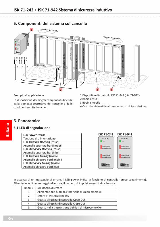
36
Italia
noISK 71-242 + ISK 71-942 Sistema di sicurezza induttivo
ISK 71-242 ISK 71-942
6. Panoramica6.1 LED di segnalazione
LED Power (verde)Tensione di alimentazioneLED Transmit Opening (rosso)Anomalia apertura bordi mobiliLED Stationary Opening (rosso)Anomalia apertura bordi fissiLED Transmit Closing (rosso)Anomalia chiusura bordi mobiliLED Stationary Closing (rosso)Anomalia chiusura bordi fissi
Power
Transmit Opening
Stationary Opening
Transmit Closing
Stationary Closing
ISK 71-242Power
Transmit Opening
Stationary Opening
Transmit Closing
Stationary Closing
ISK 71-942
Impulsi Messaggio di errore1 Alimentazione uori dall'intervallo di valori ammessi2 Errore di trasmissione ISK3 Guasto all'uscita di controllo Open Out4 Guasto all'uscita di controllo Close Out5 Guasto nella trasmissione dei dati al microcontroller
In assenza di un messaggio di errore, il LED power indica la unzione di controllo (breve spegnimento).All'emissione di un messaggio di errore, il numero di impulsi emessi indica l'errore:
ISK 71-24
Transmit OpeningStationary Opening
TransmitStationary
Power
ISK 71-242
33 11 10 1 2
2 2 2
5. Componenti del sistema sul cancello
2 4 3
1 Apertura del cancello
Chiusura del cancello
APER
TURA
del
BSS
APER
TURA
del
BSS
APER
TURA
del
BSS
CHIU
SURA
del
BSS
CHIU
SURA
del
BSS
CHIU
SURA
del
BSS
1 Dispositivo di controllo ISK 71‑242 (ISK 71‑942)2 Bobina fissa3 Bobina mobile4 Cavo d'acciaio utilizzato come mezzo di trasmissione
Esempio di applicazioneLa disposizione dei singoli componenti dipende dalla tipologia costruttiva del cancello e dalle condizioni architettoniche.
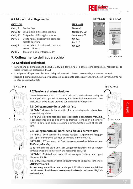
37
ISK 71-942TransmitStationary Op.Stationary Cl. Pin 4, 5Pin 6, 7Pin 8, 9
7. Collegamento dell'apparecchio7.1 Condizioni preliminari.1 Condizioni preliminariCondizioni preliminari• La tensione di alimentazione dell'ISK 71‑242 ed dell'ISK 71‑942 deve essere conorme ai requisiti per la bassa tensione di protezione (PELV).• I cavi posati all'aperto o all'esterno del quadro elettrico devono essere adeguatamente protetti.• Il grado di protezione indicato per l'apparecchio è garantito solo se i cavi vengono fissati correttamente nei relativi passacavi filettati.
Italia
no
Stationary Op.
Transmit
Stationary Cl.
P o w e r
T r a n s m i t O p e n i n gS t a t i o n a r y O p e n i n g
T r a n s m i t C l o s i n gS t a t i o n a r y C l o s i n g
I S K 7 1 - 9 4 2
Serial No.: 1 0 2 0 1 1 0 0 0 0 0
ISK 71-942 V0.0
Sta
tion
. Op
.
Tr
an
sm
it
Sta
tion
. Cl.
cl
os
in
g
di
re
ct
io
n
op
en
in
g
di
re
ct
io
n
cl
os
in
g
di
re
ct
io
n
op
en
in
g
di
re
ct
io
n
8,2 kOhm
8,2 kOhm
8,2 kOhm
8,2 kOhm
steel rope
transmission coil
fixed
transmission coil
travelling
Te
ch
nic
al d
at
a:
U =
24
V A
C/D
CI =
10
0 m
AP
= 2
,4 W
1110
9
8 7 6 5 4
321
9
8
21
7 6 5 4
1110 3
% %- + 24V AC/DC
1110 3
7 6 5 48
21
9
1110
9
8 7 6 5 4
321
% %- + 24V AC/DC
ISK 71-242 ISK 71-942
Lato ineriore
ISK 71-242 Pin 1, 2 Bobina fissaPin 3, 11 BSS piedino di fissaggio aperturaPin 3, 10 BSS piedino di fissaggio chiusura Pin 4, 5 Uscita relè al dispositivo di comando arresto aperturaPin 6, 7 Uscita relè al dispositivo di comando arresto chiusuraPin 8, 9 Tensione di alimentazione 24 V
7.2 Tensione di alimentazione.2 Tensione di alimentazioneTensione di alimentazioneCome alimentazione alla ISK 71‑242 ed alla ISK 71‑942 si devono collegare 24 V AC/DC alla coppia di morsetti 8, 9. La linea di alimentazione al relè di sicurezza deve essere protetta con un usibile appropriato.
7.3 Collegamento della bobina fissaISK 71-242: alla coppia di morsetti 1, 2 si deve collegare la bobina fissa, la polarit è qualsiasi.ISK 71-942: la bobina fissa deve essere collegata al connettore Transmit . Il collegamento alla bobina avviene tramite i connettori ad innesto orniti in dotazione oppure saldando direttamente il cavo al connet-tore.
7.4 Collegamento dei bordi sensibili di sicurezza fissiISK 71-242: I bordi sensibili di sicurezza fissi (BSS) sul piedino di fissaggio per l'apertura vengono collegati alla coppia di morsetti 3, 11 .ISK 71-942: i BSS stazionari per l'apertura vengono collegati al connettore Stationary Opening .Se ne sono presenti pi di uno, i BSS vengono collegati in serie ed il bordo terminale viene terminato con una resistenza di 8,2 kΩ. ISK 71-242: i BSS stazionari per la chiusura vengono collegati alla coppia di morsetti 3, 10 .ISK 71-942: i BSS stazionari per la chiusura vengono collegati al connettore Stationary Closing .Se non vengono utilizzati un canale per i BSS fissi o nessuno dei due canali, questi ultimi devono essere terminati con le resistenze di 8,2 kΩ in dotazione.
6.2 Morsetti di collegamento
Stationary Op.
Transmit
Stationary Cl.
Serial No.: 1 0 2 0 1 1 0 0 0 0 0
ISK 71-942 V0.0
8 7 6 5 4
910 11 1 2
3
ISK 71-242 ISK 71-942

38
Italia
noISK 71-242 + ISK 71-942 Sistema di sicurezza induttivo
7 6 5 48
1110 3
21
9
7 6 5 48
1110 3
21
9
7.5 Collegamento dei circuiti di comandoAlla coppia di morsetti 4, 5 si deve collegare il circuito di comando da sorvegliare per l'apertura (arresto apertura) ed alla coppia di morsetti 6, 7 il corrispondente circuito di comando per la chiusura (arresto chiusura). II circuiti di comando dipendono dalla corrente nominale per proteggere con un usibile appropriato o la corrente nominale per il circuiti di comando deve essere limitata da altre misure per il valore massimo.
8. Collegamento dei sensori8.1 Collegamento alla bobina SPK 54 (Figura 1)
8.2 Collegamento di più sensori ad un solo circuito (figura 2)All'ingresso dei sensori O o C si possono collegare uno o pi sensori. I singoli sensori vengono collegati in serie come illustrato in figura 2. Si possono collegare in serie al massimo 5 sensori con un cavo lungo max. 25 m. La lunghezza di un sensori può essere fino a 25 m.Prima di collegare i sensori in serie è consigliabile di misurare il valore della resistenza del circuito.
Con BSS non azionato, il valore di resistenza deve essere di 8,2 kΩ ± 500 Ω. Con BSS azionato, il valore di resistenza non deve essere maggiore di 500 Ω.
Se non viene utilizzato, un canale deve essere terminato con una resistenza di 8,2kΩ. kΩ.kΩ.Ω. .
I bordi mobili (BSS) vengono collegati alla bobina mobile.A tal fine il BSS CHIUSURA mobile viene collegato ai morsetti C della bobina mobile ed il BSS APERTURA opzionale ai morsetti O .
9. Avviamento / controllo del funzionamentoDopo aver eseguito tutti i collegamenti elettrici e collegato la tensione di alimentazione, è necessario controllare che il cancello unzioni correttamente. A tal fine azionare uno dopo l'altro tutti i bordi sensibili di sicurezza e controllare le relative reazioni del relè di sicurezza.
Figura 1: collegamento alla bobina
BSS
CHIUSURA
BSS
APERTURA
OC
Sensore 1 Sensore 2 Sensore „n“
O
CFigura 2: collegamento di più sensori, qui nell‘esempio: bordo sensibile di sicurezza
I sensori ASO non devono essere collegati in parallelo.
2222

39
Italia
no
10. Diagnosi anomalieSe il cablaggio è corretto e la tensione di alimentazione è applicata, deve accendersi solo il LED verde . Se si accende uno dei LED rossi, significa che nel sistema è presente un'anomalia che può essere individuata almeno approssimativamente mediante i LED.
LED Anomalia Eliminazione anomalieI LED non si accendono
Tensione di alimentazione assente o collegata in modo errato
Controllare i collegamenti e la tensione di aliment-azione:‑ 24 V AC/DC ai morsetti 8 9Tolleranza: ±10 %
Si accende un solo LED rosso
Bordi sensibili di sicurezza non collegati, collegati in modo errato o danneggiati
‑ Controllare i collegamenti dei rispettivi bordi sensibili di sicurezza (cavi schiacciati, ragili, ecc.)
‑ Controllare i bordi sensibili di sicurezza*
Un collegamento del bordo sensibile di sicurezza non è usato
Collegare i morsetti dei bordi sensibili di sicurezza non utilizzati tramite una resistenza da 8,2 kΩ in dotazione
Si accendono entrambi i LED rossi Transmit
Il tratto di trasmissione è guasto o montato in modo errato
‑ Osservare le istruzioni di montaggio meccanico (sistema di trasmissione di sicurezza ISK)
‑ Controllare l'usura delle bobine di trasmissione ‑ Controllare il circuito di collegamento verificando che le due bobine di trasmissione si trovino nello stesso circuito di collegamento
‑ Controllare punti di contatto cavo / corpo del cancello
‑ Controllare la tensione di alimentazione**
Bordi sensibili di sicurezza non collegati, collegati in modo errato o danneggiati
‑ Controllare i collegamenti dei rispettivi bordi sensibili di sicurezza (cavi schiacciati, ragili, ecc.)
‑ Controllare i bordi sensibili di sicurezza*
* Se l'anomalia non deriva dal cablaggio, il unzionamento dell'elettronica può essere controllato collegan-do ad ognuno degli ingressi BSS della centralina di controllo ISK 71‑242 (ISK 71‑942) (morsetti 3, 10 e morsetti 3, 11) ed alla bobina mobile (collegamenti O e C) una resistenza di 8,2 kΩ. Se dopo questa verifica l'elettronica unziona correttamente, è necessario controllare i bordi sensibili di sicurezza mediante un ohmetro. A tal fine il collegamento del BSS alla centralina di controllo o alla bobina mobile deve essere interrotto e collegato ad un ohmetro.
Con bordo sensibile di sicurezza non azionato, il valore della resistenza deve essere di 8,2 kΩ ±500 Ω. Con bordo sensibile di sicurezza azionato, il valore della resistenza non deve essere maggiore di 500 Ω.
** Se sono accesi entrambi i LED per i BSS mobili (Transmit Opening e Transmit Closing), significa che è presente un'anomalia nel sistema di trasmissione induttivo. Le cause pi requenti dell'anomalia sono in questo caso collegamenti di cattiva qualit alle bobine, componenti del sistema a cavo non installati cor-rettamente (vedere le istruzioni di montaggio del sistema di trasmissione di sicurezza ISK) o una tensione di alimentazione eccessivamente bassa.
Il circuito del cavo deve avere un valore massimo di resistenza di 3 Ω. Il valore della resistenza può essere misurato scollegando il cavo d'acciaio dal morsetto di terra e misurando tra l'estremit finale del cavo ed il morsetto di terra.

40
Italia
noISK 71-242 + ISK 71-942 Sistema di sicurezza induttivo
12. Dati tecniciTensione di alimentazione UE 24 V AC/DC ±10% IE = 85 mA; Imax = 180mA (100ms)
Resistenza terminale dei bordi sensibili di sicurezza valore nominale nom = 8,2 kΩ soglia superiore AO > 20 kΩ soglia ineriore AU < 2,5 kΩ
Portata dei contatti Corrente nominale DC 3 A 30 V DC Corrente nominale AC 3 A 30 V AC Vita meccanica >106 azionamenti
Tempi di commutazione del relè di sicurezza Tempo di intervento < 10 ms (BSS fissi) < 30 ms (ISK) Tempo di attivazione 500 ms
MontaggioZoccolo per il montaggio della guida ad innesto DIN da 35 mm
Custodia Alloggiamento per zoccolo a 11 poli DIN con zoccolo a innesto per guida di montaggio da 35 mmDimensioni (HxLxP) Custodia 82 x 38 x 84 mm
Custodia con passacavo filettato 82 x 38 x 110 mm
Grado di protezione IP20
Peso 225 g
Campo di temperatura ‑25°C . . +55°C
Sezione dei cavi di collegamento conduttore rigido o flessibile 0,75‑1,5 mm2
Omologazioni DIN EN ISO 13849‑1:2008 Categoria 3 PL e MTTFd 170 anni, DC 91% Elettronica MTTFd 1616 anni, DC 99 % Elettromeccanica B10d 1000000 MTTFd 190 anni (Nop 52560) Dispositivo di sicurezza conorme a DIN EN 12978
Tutte le tensioni collegate al relè di sicurezza devono essere tensioni con disaccoppiamento sicuro!
Prüfbericht Nr.:12 205 399386-000
Zertifikat Nr.:44 780 12 399386
EG Baumuster Nr.: 44 205 12 399386
1110
9
8 7 6 5 4
321
Transmit OpeningStationary Opening
TransmitStationary
Power
ISK 71-942
38
82
84
26
D-33154 Salzkottenwww.asosafety.com
1110
9
8 7 6 5 4
321
Transmit OpeningStationary Opening
TransmitStationary
Power
ISK 71-242
38
82
84
26
D-33154 Salzkottenwww.asosafety.com
ISK 71-242
ISK 71-942
11. Messa fuori servizio e smaltimentoI prodotti ASO sono previsti esclusivamente per l'uso industriale (B2B). I prodotti non pi utilizzati devono essere smaltiti conormemente alle norme locali, regionali e nazionali. I prodotti possono essere anche restituiti alla ASO che provvede a smaltirli correttamente.

41
Italia
no
13. Dichiarazione di conformità CE
Dichiariamo che i seguenti prodotto:
ISK 71-242 (codice articolo 1204‑0100, ormato del numero di serie mmnnnnn)ISK 71-942 (codice articolo 1204‑0110, ormato del numero di serie mmnnnnn)
dispositivi di trasmissione induttiva con sistema di comando di sicurezza da combinare con bordi sensibili di sicurezza per evitare i pericoli derivanti dai punti di schiacciamento e di taglio di sistemi di cancelli e portoni, per progettazione e modello e nel tipo da noi messo in commercio sono conormi ai requisiti ondamentali per la sicurezza e la salute previsti dalle seguenti direttive e norme CE:
Direttiva sulle macchine 2006/42/CEEN ISO 13849‑1:2008EN ISO 13849‑2:2008EN 61000‑6‑2:2005EN 61000‑6‑3:2007
Prova di omologazione CENotified Bod 0044TÜV NOD CET GmbHLangemarckstraße 20D‑45141 EssenN. certificazione prova di omologazione CE: 44 205 12 399386
La presente dichiarazione di conormit non esonera il progettista/produttore della mac-china dall'obbligo di verificare la conormit alla direttiva CE della macchina complessi-va in cui viene installato questo prodotto.
Produttore ed incaricato alla documentazione:ASO, Antriebs‑ und Steuerungstechnik GmbH,Am Grarock 8, D‑33154 Salzkotten
Salzkotten, XX/XX/2012
Helmut Friedrich(Amministratore ed incaricato alla documentazione)

42

43
Nede
rland
s
ISK 71-242 + ISK 71-942 Inductief veiligheidsrelais
Technische en bedrijfsrelevante wijzigingen met betrekking tot de producten en toestellen in deze documentatie zijn allen tijde, ook zonder vooraankondiging, voor-behouden.
1. Inhoudsopgave
1. Inhoudsopgave . . . . . . . . . . . . . . . . . . . . . . . 43
2. Algemene veiligheidsbepalingen en veiligheidsmaatregelen . . . . . . . . . . . . . . . . . . 44
3 . Algemeen en Functie . . . . . . . . . . . . . . . . . . . . 45
4 . Correct gebruik . . . . . . . . . . . . . . . . . . . . . . . 45
5. Ssteemcomponenten op de poort . . . . . . . . . . . . 46
6 . Toesteloverzicht . . . . . . . . . . . . . . . . . . . . . . . 466 .1 Signaalweergaven . . . . . . . . . . . . . . . . . . . . . . . . . . 466 .2 Aansluitklemmen . . . . . . . . . . . . . . . . . . . . . . . . . . 47
7. Aansluiting van het toestel . . . . . . . . . . . . . . . . . 477.1 Voorwaarden.1 Voorwaarden . . . . . . . . . . . . . . . . . . . . . . . . . . . . 477.2 Voedingsspanning.2 Voedingsspanning . . . . . . . . . . . . . . . . . . . . . . . . . . 477 .3 Aansluiting vaste spoelkern . . . . . . . . . . . . . . . . . . . . 477 .4 Aansluiting vaste contactlijsten . . . . . . . . . . . . . . . . . . 477 .5 Aansluiting stuurstroomkringen . . . . . . . . . . . . . . . . . . 48
8 . Aansluiten van de meebewegende signaalgevers . . . . 488 .1 Aansluiting aan de meebewegende spoelkern . . . . . . . . . . 488.2 Aansluiting van meerdere signaalgevers per Aansluiti ng van meerdere signaalgevers perAansluiting van meerdere signaalgevers per
signaalgevercircuit . . . . . . . . . . . . . . . . . . . . . . . . . 48
9 . Inbedrijstelling en unctiecontrole . . . . . . . . . . . . . 48
10. Foutendiagnose . . . . . . . . . . . . . . . . . . . . . . . 49
11 . Buitenbedrijstelling en avoer . . . . . . . . . . . . . . . 50
12. Technische gegevens . . . . . . . . . . . . . . . . . . . . 50
13 . EG‑verklaring van overeenstemming . . . . . . . . . . . 51

44
Nede
rland
sISK 71-242 + ISK 71-942 Inductief veiligheidsrelais
2. Algemene veiligheidsbepalingen en veiligheidsmaatregelen • Fabrikant en gebruiker van de installatie / machine, waarop de veiligheidsinrichting wordt gebruikt, zijn
ervoor verantwoordelijk om alle geldende veiligheidsvoorschriften en ‑regels op eigen verantwoordelijk‑ heid a te stemmen en te respecteren.
• De veiligheidsinrichting garandeert in combinatie met de bovengeschikte besturing een unctionele veilig-heid, maar niet de veiligheid van de complete installatie / machine. Voordat de machine wordt gebruikt, is daarom een veiligheidsobservatie van de complete installatie / machine conorm de machinerichtlijn 2006/42/EG o de betreffende productnorm noodzakelijk.
• De bedieningshandleiding moet permanent op de installatieplaats van de veiligheidsinrichting beschikbaar zijn .
Ze moet door iedereen die zich bezighoudt met bedienings‑, onderhouds‑ o servicewerkzaamheden van de veiligheidsinrichting, grondig worden gelezen en toegepast.
• De installatie en inbedrijstelling van de veiligheidsinrichting mag enkel door vakpersoneel gebeuren, dat vertrouwd is met deze bedieningshandleiding en de geldende voorschriften over arbeidsveiligheid en ongevallenpreventie. De aanwijzingen in deze handleiding moeten absoluut nageleed worden.
Elektrische werkzaamheden mogen enkel door elektriciens worden uitgevoerd.• De veiligheidsvoorschriften betreffende elektrotechniek en die van de bedrijsvereniging moeten in acht
worden genomen.• Het relais dient bij werkzaamheden hieraan spanningsvrij geschakeld, op spanningsvrijheid gecontroleerd
en tegen opnieuw inschakelen beveiligd te worden.• Als de potentiaalvrije contacten van de relaisuitgangen met een gevaarlijke spanning extern gevoed worden,
dan moet gegarandeerd worden dat deze bij werkzaamheden aan het relais eveneens uitgeschakeld worden.
• Het relais bevat enkel onderhoudsvrije onderdelen. Door eigenhandige ombouwwerken resp. herstellingen aan het relais vervalt elke garantie en aansprakelijkheid van de abrikant.
• Het beveiligingsssteem dient met passende tijdsintervallen door deskundigen gecontroleerd en te allen tijde inzichtelijk gedocumenteerd te worden.
Veiligheidsaanwijzingen • Met het relais is zowel werking op 230 V als met 24 V AC/DC mogelijk. Door de bedrijsspanning op de
verkeerde klemmen aan te sluiten kan het relais kapot gaan.• Het relais dient in een schakelkast gemonteerd te worden.• Niet in directe nabijheid van sterke warmtebronnen monteren.• Bij capacitieve en inductieve verbruikers dient voor voldoende beveiligingsschakeling gezorgd te worden.
Het relais is conform EN ISO 13849-1 „Onderdelen van besturingssystemen met een veilig-heidsfunctie“ voor cat. 3 geconcipieerd. Voor de naleving van cat. 3 is het relais redundant opgebouwd, met twee gedwongen veiligheidsrelais per kanaal, die elkaar bewaken.
De eisen van de poortnormen EN 12978 „Veiligheidsvoorzieningen voor automatisch werkende deuren en hekken“ en EN 12453 „Gebruiksveiligheid van aangedreven deuren“ worden eveneens vervuld.
In geval van het niet in acht nemen of opzettelijk misbruik vervalt de aansprakelijkheid van de fabrikant.

45
Nede
rland
s
3. Algemeen en FunctieHet kabeloverdrachtsssteem ISK levert de oplossing voor het probleem om bewegende signaalgevers te verbinden met een stationaire analse zonder mechanische belasting. De communicatie tussen de bewegende signaalgevers en de analse‑elektronica berust hierbij op een inductieve basis. De bewakingselektronica induceert hiertoe een requentie op een spoelkern die in een gesloten geleidende lus geïntegreerd is.
De tweede spoelkern waar de bewegende signaalgevers op aangesloten worden, ontvangt deze requentie en stuurt bij kabelbreuk o bij activering van een signaalgever een dienovereenkomstig antwoordsignaal naar de analse‑elektronica.
Het compacte en montagevriendelijke veiligheidsrelais is geconcipieerd voor buitengebruik en kan met 230 V netspanning o 24 V AC/DC worden gevoed. Op het relais kunnen max. vier circuits met veiligheidscontactlijsten aangesloten worden. Voor de veiligheids‑ contactlijsten (SKL) op het poortblad staan twee kanalen (SKL open‑beweging en SKL dicht‑beweging), en voor de veiligheidscontactlijsten op de steunpaal eveneens twee kanalen ter beschikking. De op het poort-blad meebewegende veiligeidscontactlijsten worden door het kabeloverbrengingsssteem contactloos en slijtvast bewaakt. De vaste veiligheidscontactlijsten worden direct op het relais aangesloten. Het relais bewaakt deze vier circuits met veiligheidscontactlijsten permanent op activering o onderbreking (kabelbreuk). Bij een storing wordt aan het betreffende veiligheidscontactlijstcircuit n van de twee stop‑ commando’s toegewezen (stop in open‑richting o stop in dicht‑richting). Om een ruststroombewaking van het complete ssteem mogelijk te maken, is in de eindlijst van het respectievelijke veiligheidscontactlijst‑ circuit een asluitweerstand geïntegreerd. Als de gewenste ruststroom stroomt, dan zijn de uitgangrelais aangestuurd en de schakelcontacten gesloten. Als het schakelelement geactiveerd wordt o het signaal‑ gevercircuit onderbroken wordt, gaan de relaisschakelcontacten open.
De schakeltoestanden van de relais en de voorhanden bedrijsspanning worden door LED's weergegeven.
4. Correct gebruikHet relais ISK 71‑242 (ISK 71‑942) kann deze veiligheidsrelevante taak alleen vervullen als deze correct wordt toegepast.
Het veiligheidsoverdrachtsssteem ISK 71‑242 (ISK 71‑942) is ontworpen voor het analseren van stationaire en meebewegende veiligheidscontactlijsten met constante weerstand van 8,2 KΩ.
Een ander o daarvan awijkend gebruik geldt als niet correct. Voor schade die door een niet reglementair gebruik ontstaat, is de abrikant niet aansprakelijk.
Voor het gebruik in speciale toepassingen moet de abrikant toestemming verlenen.
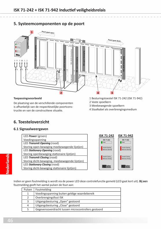
46
Nede
rland
sISK 71-242 + ISK 71-942 Inductief veiligheidsrelais
ISK 71-242 ISK 71-942
6. Toesteloverzicht6.1 Signaalweergaven
LED Power (groen)VoedingsspanningLED Transmit Opening (rood)Storing open‑beweging meebewegende lijst(en)LED Stationary Opening (rood)Storing openbeweging stationaire lijst(en)LED Transmit Closing (rood)Storing dicht‑beweging, meebewegende lijst(en)LED Stationary Closing (rood)Storing dicht‑beweging stationaire lijst(en)
Power
Transmit Opening
Stationary Opening
Transmit Closing
Stationary Closing
ISK 71-242Power
Transmit Opening
Stationary Opening
Transmit Closing
Stationary Closing
ISK 71-942
Pulsen Foutmelding1 Voedingsspanning buiten geldige waardebereik2 Overbrengingsout ISK3 Uitgangsbesturing „Open” gestoord4 Uitgangsbesturing „Close” gestoord5 Gegevensoverdracht tussen microcontrollers gestoord
Indien er geen outmelding is wordt via de power LED deze controleunctie gemeld (LED gaat kort uit). Bij eenBij een outmelding geeft het aantal pulsen de out aan:
5. Systeemcomponenten op de poort
ISK 71-24
Transmit OpeningStationary Opening
TransmitStationary
Power
ISK 71-242
33 11 10 1 2
2 2 2
2 4 3
1 Poort gaat open
Poort gaat dicht
SKL
open
bew
egin
g
SKL
open
bew
egin
g
SKL
open
bew
egin
g
SKL
dich
t-be
weg
ing
SKL
dich
t-be
weg
ing
SKL
dich
t-be
weg
ing
1 Besturingstoestel ISK 71‑242 (ISK 71‑942)2 Vaste spoelkern3 Meebewegende spoelkern4 Staalkabel als overbrengingsmedium
ToepassingsvoorbeeldDe plaatsing van de verschillende componenten is afhankelijk van de respectievelijke poortcons-tructie en van de constructieve situatie.

47
7. Aansluiting van het toestel7.1 Voorwaarden.1 VoorwaardenVoorwaarden• De voedingsspanning van de ISK 71‑242 en de ISK 71‑942 moet aan de voorwaarden voor unctionele laagspanning met veilige scheiding beantwoorden.• Leidingen, die buitenshuis o buiten de schakelkast gelegd worden, moeten overeenkomstig beschermd worden.• De voor het toestel aangegeven beschermingsklasse is pas gegarandeerd, wanneer de toevoerleidingen correct in de schroeverbindingen geklemd zijn.
Nede
rland
s
Stationary Op.
Transmit
Stationary Cl.
P o w e r
T r a n s m i t O p e n i n gS t a t i o n a r y O p e n i n g
T r a n s m i t C l o s i n gS t a t i o n a r y C l o s i n g
I S K 7 1 - 9 4 2
Serial No.: 1 0 2 0 1 1 0 0 0 0 0
ISK 71-942 V0.0
Sta
tion
. Op
.
Tr
an
sm
it
Sta
tion
. Cl.
cl
os
in
g
di
re
ct
io
n
op
en
in
g
di
re
ct
io
n
cl
os
in
g
di
re
ct
io
n
op
en
in
g
di
re
ct
io
n
8,2 kOhm
8,2 kOhm
8,2 kOhm
8,2 kOhm
steel rope
transmission coil
fixed
transmission coil
travelling
Te
ch
nic
al d
at
a:
U =
24
V A
C/D
CI =
10
0 m
AP
= 2
,4 W
1110
9
8 7 6 5 4
321
9
8
21
7 6 5 4
1110 3
% %- + 24V AC/DC
1110 3
7 6 5 48
21
9
1110
9
8 7 6 5 4
321
% %- + 24V AC/DC
ISK 71-242 ISK 71-942
Onderzijde
ISK 71-942TransmitStationary Op.Stationary Cl. Pin 4, 5Pin 6, 7Pin 8, 9
ISK 71-242 Pin 1, 2 Vaste spoelkernPin 3, 11 SKL Steunpaal OpenenPin 3, 10 SKL Steunpaal SluitenPin 4, 5 elais‑uitgang naar besturing Stop OpenenPin 6, 7 elais‑uitgang naar besturing Stop SluitenPin 8, 9 Voedingsspanning 24 V
7.2 Voedingsspanning.2 VoedingsspanningVoedingsspanningAls voeding moet bij de ISK 71‑242 en de ISK 71‑942 op elk klemmen‑ paar 8, 9 24 V AC/DC aangesloten worden. De toevoerleiding naar de veiligheidsrelais moet worden beschermd met een geschikte zekering.
7.3 Aansluiting vaste spoelkernISK 71-242: Aan het klemmenpaar 1, 2 moet de vaste spoelkern aan-gesloten worden, waarbij de polariteit om het even is.ISK 71-942: De vaste spoelkern met de insteekplaats Transmit verbinden. De aansluiting aan de spoelkern gebeurt via de meegeleverde krimphulzen o door direct vastsolderen van de leiding aan de stekker.
7.4 Aansluiting vaste contactlijstenISK 71-242: De stationaire veiligheidscontactlijst(en) (SKL) dient (dienen) op de steunpaal voor de open‑beweging aangesloten te worden op het klemmenpaar 3, 11 .ISK 71-942: De stationaire SKL('s) voor de open‑beweging wordt (worden) met de insteekplaatsStationary Opening verbonden. Bij verschillende SKL worden deze in serie geschakeld en de eindlijst met 8,2 kΩ age-sloten. ISK 71-242: De stationaire SKL('s) voor de dicht‑beweging dient (dienen) overeenkomstig aangesloten te worden op het klemmenpaar 3, 10 .ISK 71-942: De stationaire SKL('s) voor de dicht‑beweging wordt (worden) met de insteekplaats Stationary Closing verbonden.Als er een kanaal voor de stationaire SKL's of eventueel beide kanalen niet wordt/worden gebruikt, dienen de kanalen bezet te worden met de meegeleverde 8,2 kΩ-weerstanden.
6.2 Aansluitklemmen
Stationary Op.
Transmit
Stationary Cl.
Serial No.: 1 0 2 0 1 1 0 0 0 0 0
ISK 71-942 V0.0
8 7 6 5 4
910 11 1 2
3
ISK 71-242 ISK 71-942

48
Nede
rland
sISK 71-242 + ISK 71-942 Inductief veiligheidsrelais
7 6 5 48
1110 3
21
9
7 6 5 48
1110 3
21
9
7.5 Aansluiting stuurstroomkringenAan het klemmenpaar 4, 5 moet de te bewaken stuurstroomkring voor de open‑beweging (stop‑open‑beweging) en aan het klemmenpaar 6, 7 de overeenkomstige stuurstroomkring voor de dicht‑beweging (stop‑dicht‑beweging) aangesloten worden. De stuurstroomkringen zijn afhankelijk van de nominale stroom te beschermen met een geschikte zekering o de nominale stroom van de stuurstroomkringen te beperken door andere maatregelen om de maximale waarde.
ASO-Signalgeber dürfen nicht parallel geschaltet werden.
Afbeelding 1: Schakelaansluiting op spoelkern
SKL
Dicht-beweging
SKL
Open-beweging
OC
8. Aansluiten van de meebewegende signaalgevers8.1 Aansluiting aan de spoelkern SPK 54 (afbeelding 1)
8.2 Aansluiting van meerdere signaalgevers per signaalgevercircuit (afbeelding 2)Op signaalgeveringang O resp . C kunnen n o meerdere signaalgevers worden aangesloten. Hiertoe dienen de azonderlijke signaalgevers als in afbeelding 2 in serie geschakeld te worden. Er kunnen maximaal vij signaalgevers met een totale kabellengte van max. 25 m in serie geschakeld worden. De lengte van een signaalgever kan tot 25 m.Voor het aansluiten van de in serie geschakelde signaalgevers is het aan te bevelen om de weerstandswaarde van de schakeling te meten.Bij niet‑geactiveerde SKL moet de weerstand 8,2 kΩ ± 500 Ω bedragen. Als de SKL geactiveerd is, mag de weerstand 500 Ω niet overschrijden.
Als een kanaal niet gebruikt wordt, moet dit kanaal bezet worden met een 8,2kΩ -weer--weer-stand .
De meebewegende lijsten (SKL's) worden met de meebewegende spoelkern verbonden.Hiertoe dient de meebewegende SKL DICHT-beweging met de aansluiting C van de meebewegende spoelkern en de optionele SKL OPEN beweging met de aanslui-ting O verbonden te worden.
9. Inbedrijfstelling / FunctiecontroleNa de overeenkomstige aansluiting van alle elektrische verbindingen en inschakeling van de voedingsspanning, moet de poort op correcte unctie gecontroleerd worden. Daartoe moeten alle veiligheidscontactlijsten n voor n geactiveerd worden en de overeenkomstige reacties van het relais gecontroleerd worden.
Afbeelding 2: Bedrading bij meerdere signaalgevers, hier bijvoorbeeld veiligheidscontactlijst
Signaalgever 1 Signaalgever 2 Signaalgever „n“
O
C2222

49
Nede
rland
s
11. FoutendiagnoseBij een correcte bedrading en aansluiting van de voedingsspanning mag enkel de groene LED branden. Wan-neer n van de rode LED's oplicht, zit er in het ssteem een out, die met behulp van de LED's kan worden opgespoord.
LED Fout Verhelping van de foutLED's branden niet
Voedingsspanning ontbreekt,te laag o out aangesloten
Aansluitingen en voedingsspanning controleren:‑ 24 V AC/DC op klemmen 8 9Tolerantiebereik: ±10 %
enkele rode LED brandt
Contactlijst(en) niet aangesloten, out aangesloten o deect
‑ Aansluitingen van de betreffende contactlijst controleren (beschadigde toevoerleidingen, brok-kelige toevoerleidingen etc.)
‑ Veiligheidscontactlijst(en) controleren*
Een contactlijst‑aansluiting wordt niet gebruikt
Niet gebruikte contactlijst‑aansluitingen permanent met n van de meegeleverde 8,2 kΩ‑weerstanden overbruggen.
beide rode Transmit LED's branden
Overbrengingstraject is verstoordo out gemonteerd
‑ Mech. montagehandleiding in acht nemen (ISK veiligheidsoverbrengingsssteem)
‑ Overbrengingskernen op slijtage controleren. ‑ Kabelcircuit controleren; hier moet erop gelet worden, dat beide overbrengingskernen zich binnen het kabelcircuit bevinden
‑ Contactpunten kabel / poortlichaam controleren.‑ Voedingsspanning controleren**
Contactlijst(en) niet aangesloten, out aangesloten o deect
‑ Aansluitingen van de betreffende contactlijst controleren (beschadigde toevoerleidingen, brok-kelige toevoerleidingen etc.)
‑ Veiligheidscontactlijst(en) controleren*
* Als de out niet in de bedrading zit, kan de unctie van de elektronica door bezetting van alle SKL‑ingangen aan de ISK 71‑242 (ISK 71‑942) analse‑elektronica (klemmen 3, 10 en klemmen 3, 11) en aan de meebe-wegende spoelkern (aansluitingen O en C) met telkens n 8,2 kΩ weerstand gecontroleerd worden. Als de elektronica daarna correct werkt, moeten de veiligheidscontactlijsten met een weerstandsmeettoestel gecontroleerd worden. Daarvoor moet de respectievelijke verbinding van de SKL naar de analse‑elek-tronica o naar de meebewegende spoelkern losgemaakt en met een weerstandsmeettoestel verbonden worden.
Bij niet‑geactiveerde veiligheidscontactlijst moet de weerstand 8,2 kΩ ±500 Ω bedragen. Als de veilig-heidscontactlijst geactiveerd is, mag de weerstand 500 Ω niet overschrijden.
** Als de beide LED’s voor de meebewegende SKL's (Transmit Opening en Transmit Closing) branden, is een out in het inductieve overbrengingsssteem voorhanden. De meest voorkomende oorzaken hiervoor zijn slechte verbindingen op de spoelkernen, niet correct geïnstalleerde kabelssteemcomponenten (zie montagehandleiding ISK‑veiligheidsoverbrengingsssteem) o een ontoelaatbaar lage voedingsspan-ning .
De kabellus mag een maximale weerstandswaarde van 3 Ω hebben. De weerstandswaarde kan door los-maken van de staalkabel van de aardingsklem en daarna meten tussen staalkabeluiteinde en aardingsklem bepaald worden.
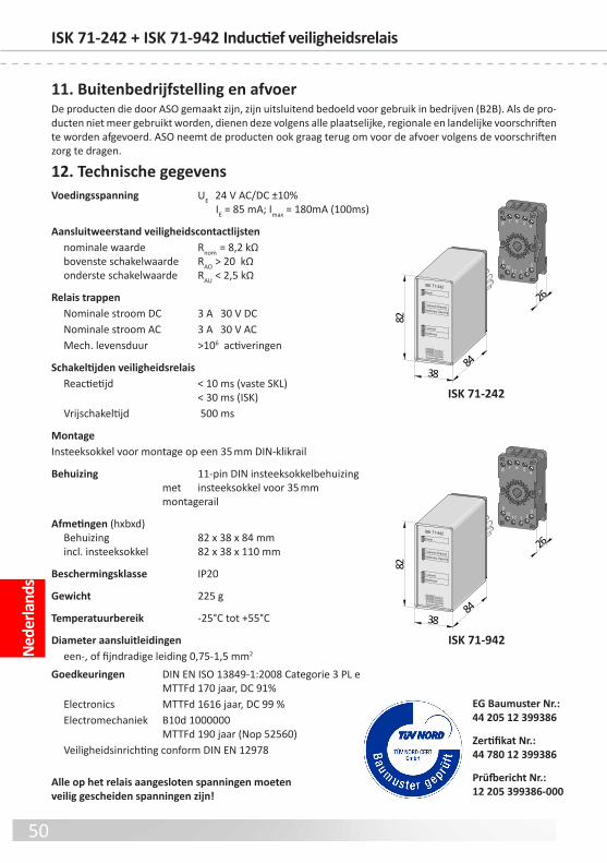
50
Nede
rland
sISK 71-242 + ISK 71-942 Inductief veiligheidsrelais
12. Technische gegevensVoedingsspanning UE 24 V AC/DC ±10% IE = 85 mA; Imax = 180mA (100ms)
Aansluitweerstand veiligheidscontactlijsten nominale waarde nom = 8,2 kΩ bovenste schakelwaarde AO > 20 kΩ onderste schakelwaarde AU < 2,5 kΩ
Relais trappen Nominale stroom DC 3 A 30 V DC Nominale stroom AC 3 A 30 V AC Mech. levensduur >106 activeringen
Schakeltijden veiligheidsrelais eactietijd < 10 ms (vaste SKL) < 30 ms (ISK) Vrijschakeltijd 500 ms
MontageInsteeksokkel voor montage op een 35 mm DIN‑klikrail
Behuizing 11‑pin DIN insteeksokkelbehuizing met insteeksokkel voor 35 mm montagerail
Afmetingen (hxbxd) Behuizing 82 x 38 x 84 mm incl. insteeksokkel 82 x 38 x 110 mm
Beschermingsklasse IP20
Gewicht 225 g
Temperatuurbereik ‑25°C tot +55°C
Diameter aansluitleidingen een‑, o fijndradige leiding 0,75‑1,5 mm2
Goedkeuringen DIN EN ISO 13849‑1:2008 Categorie 3 PL e MTTFd 170 jaar, DC 91% Electronics MTTFd 1616 jaar, DC 99 % Electromechaniek B10d 1000000 MTTFd 190 jaar (Nop 52560) Veiligheidsinrichting conorm DIN EN 12978
Alle op het relais aangesloten spanningen moeten veilig gescheiden spanningen zijn!
Prüfbericht Nr.:12 205 399386-000
Zertifikat Nr.:44 780 12 399386
EG Baumuster Nr.: 44 205 12 399386
1110
9
8 7 6 5 4
321
Transmit OpeningStationary Opening
TransmitStationary
Power
ISK 71-942
38
82
84
26
D-33154 Salzkottenwww.asosafety.com
1110
9
8 7 6 5 4
321
Transmit OpeningStationary Opening
TransmitStationary
Power
ISK 71-242
38
82
84
26
D-33154 Salzkottenwww.asosafety.com
ISK 71-242
ISK 71-942
11. Buitenbedrijfstelling en afvoerDe producten die door ASO gemaakt zijn, zijn uitsluitend bedoeld voor gebruik in bedrijven (B2B). Als de pro-ducten niet meer gebruikt worden, dienen deze volgens alle plaatselijke, regionale en landelijke voorschriften te worden agevoerd. ASO neemt de producten ook graag terug om voor de avoer volgens de voorschriften zorg te dragen.

51
Nede
rland
s
13. EG-verklaring van overeenstemming
Hierbij verklaren wij dat de hieronder genoemde product:
ISK 71-242 (artikelnummer 1204‑0100, ormaat serienummer mmnnnnn)ISK 71-942 (artikelnummer 1204‑0110, ormaat serienummer mmnnnnn)
Inductieve overdrachtsinrichting met veiligheidsschakelssteem ter combinatie met schakellijsten voor het vermijden van gevaar op knel‑ en klemplaatsen bij poortsstemen op basis van het ontwerp en constructie en in de door ons in omloop gebrachte uitvo-ering voldoet aan de desbetreffende undamentele veiligheids‑ en gezondheidseisen uit de volgende EG‑richtlijnen en normen:
EG - machinerichtlijn 2006/42/EGEN ISO 13849‑1:2008EN ISO 13849‑2:2008EN 61000‑6‑2:2005EN 61000‑6‑3:2007
EG - typeonderzoekNotified Bod 0044TÜV NOD CET GmbHLangemarckstraße 20D‑45141 EssenEG tpegoedkeuringscertificaatnr.: 44 205 12 399386
Deze verklaring van overeenstemming ontbindt de constructeur/abrikant van de ma-chine niet van zijn plicht om de conormiteit van de totale machine waarop dit product wordt aangebracht in overeenstemming met de EG‑richtlijn te waarborgen.
Fabrikant en documentatie-gevolmachtigde:ASO, Antriebs‑ und Steuerungstechnik GmbH,Am Grarock 8, D‑33154 Salzkotten
Salzkotten, XX‑XX‑2012
Helmut Friedrich(directeur en documentatie‑gevolmachtigde)

52
Deutsch 12.DB.04.111 Technische Daten ev 02 Technische Änderungen vorbehalten.Für Irrtümer und Druckehler kann keine Haftung übernommen werden.
Antriebs‑ und SteuerungstechnikAm Grarock 8 • D‑33154 Salzkotten Tel.: +49 (0) 5258/9327‑0 • Fax: +49 (0) 5258/9327‑99www.asosaet.com • e‑mail: [email protected]
12.DB.04.111 Technical Specifications ev 02 Subject to technical modifications.No liabilit can be assumed or errors or misprints.
12.DB.04.111 Donnes techniques v 02 Sous rserve de modifications techniques.Nous dclinons toute responsabilit en cas d‘erreurs et de autes d‘impression.
12.DB.04.111 Dati tecnici ev 02 Con riserva di modifiche tecniche.Si declina qualsiasi responsabilit per errori ed errori di stampa.
12.DB.04.111 Technische gegevens ev 02 Technische wijzigingen voorbehouden.Wij zijn niet aansprakelijk voor vergissingen en drukouten.
English
Français
Italiano
Nederlands


![942 bekey[2]](https://img.pdfslide.us/doc/110x75/54996dd0b479593d4d8b5699/942-bekey2.jpg)