Embed Size (px)
Citation preview
I. INTRODUCTION
The aim of this work is to improve muscle activated human body models (HBMs) for integral safety. In standard
applications muscles are mainly modelled as straight lines, connecting origin and insertion areas. Due to
ligaments, bone surfaces, etc., muscles in human bodies do not operate like straight‐line vectors; rather they are
guided along a specific, curved path. In the literature, different strategies exist to achieve a more physiological
representation of muscle paths within HBMs. In [1] a new open‐source, advanced muscle model in LS‐Dyna, based
on the formulation of the Hill model reported in [2], is introduced. Main advantages of the new user‐defined
muscle model are easier parameterisation, inclusion of activation dynamics and higher calculation efficiency.
However, the standard routing element of the standard LS‐Dyna muscle material *ELEMENT_BEAM_PULLEY is not
applicable for the newly defined muscle model, because of the formulation as user‐defined material. Therefore,
in LS‐Dyna a new approach is used to include the routing functionality.
II. METHODS
The main approach of this work was to divide the standard modelled muscle (lMTC) into a shorter one (lbeam)
plus standard LS‐Dyna elements with total length loffset, see Fig. 1. These additional elements can be added to both
sides of the muscle element and should be capable of routing applications. For example combinations of seatbelt‐
(*MAT_SEATBELT) and slipring‐elements (*ELEMENT_SEATBELT_SLIPRING) are suitable. Internally the subtracted
muscle length loffset, which is an input of the muscle model, is added to the modelled beam length. Therefore the
muscle dynamics are calculated with the correct length of the whole muscle lMTC = lBeam + loffset, including the length
of the guided standard LS‐Dyna elements. After successful validation with a single piglet muscle, see [3], the
upper‐extremity parts of the ViVA‐OpenHBM [4] were extracted and equipped with active one‐dimensional
muscle elements. The newly implemented muscle routing strategy was used for guiding the tricep muscles. Fig. 2
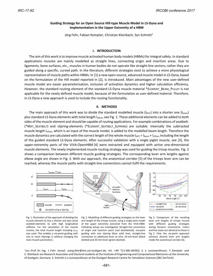
shows a comparison between different muscle guiding strategies. The corresponding lever arm lengths against
elbow angle are shown in Fig. 3. With our approach, the anatomical corridor [5] of the triceps lever arm can be
reached, whereas the muscle paths with straight‐line connections cannot fulfil the requirements.
Fig. 1. Illustration of the approach of dividing the muscle element a) into a shorter one plus serial seatbelt‐elements b) with high longitudinal stiffness. For the calculation of the muscle routine, the total muscle length including loffset was used. This enables a via‐point‐guiding with one or more sliprings c) without changing the main muscle parameters.
Fig. 2. Modelling of different guiding strategies on the lever arm length of the triceps muscle, using a single‐joint model of the upper extremity extracted from the ViVA‐HBM. Following setups are investigated: Straight‐line connection of origin and insertion point (red dashdotted), via‐point guiding with one slipring (blue solid line), straight‐line connection to additional lever at ulna: 10 mm‐lever (black dotted) and 20 mm‐lever (green dashed).
Fig. 3. Comparison of the resulting lever arm lengths of triceps muscle with different guiding strategies during forearm movements. Colors and line styles are identical to those in Fig. 2. Only the via‐point approach achieves desired lever arm lengths inside the anatomical corridor [4].
1Jun.‐Prof. Dr.‐Ing. J. Fehr (email: [email protected]‐stuttgart.de; tel: +49 711‐685‐66392) is a Juniorprofessor, F. Kempter and C. Kleinbach are Research Associates and Doctoral students at the Institute of Engineering and Computational Mechanics at the University of Stuttgart, Germany. S. Schmitt is a Juniorprofessor at the Stuttgart Research Centre for Simulation Sciences (SRC SimTech)
Jörg Fehr, Fabian Kempter, Christian Kleinbach, Syn Schmitt1
Guiding Strategy for an Open Source Hill-type Muscle Model in LS-Dyna and Implementation in the Upper Extremity of a HBM
IRC-17-92 IRCOBI conference 2017
-681-
Overall the upper extremity model is activated by nine muscles, see Fig. 4. One main difficulty in muscle modelling is the correct setting of the muscle parameters. By choosing anatomical origin and insertion points for each muscle, the modelled lengths are nearly identical to the real muscle‐tendon‐lengths in the human body. This enables the usage of anatomical data for the specific muscle parameters such as optimal muscle fiber length lCE,opt. For lCE,opt we used values presented in [6] and scaled them with the ratio of the length of radius bones of the midsized male THUMS‐HBM [7] and the midsized female ViVA‐OpenHBM. With the second length‐dependent muscle parameter lSEE0, describing the resting length of the tendon, it is possible to define the optimal length of the modelled muscle. This parameter was used for a basic fitting of the isometric torque vs. elbow angle curve. An optimal parameter fitting is not the object of this work. The force parameters Fmax, representing the maximal force of the contractile element [2], were used to match the maximum isometric torques, measured in elbow extension and flexion experiments with female subjects [9]. The unspecific muscle parameters were adopted from [10], in which also the Hill formulation reported in [2] was used.
Fig. 4. Complete model of the upper extremity with nine implemented muscle elements representing the muscles biceps long head (BILH), biceps short head (BISH), brachialis (BRAC), brachioradialis (BRAD), pronator teres (PRTE), extensor carpi radialis longus (ECRL), triceps long head (TRLO), triceps lateral head (TRLA) and triceps medial head (TRME).
Fig. 5. Maximal isometric torque against elbow position for flexion (top) and extension (bottom). As first targets we used experimental data from male subjects [8], scaled for a female HBM (black dashed). Comparison between optimal elbow position of all flexors at 100° (blue) and changed values for BILH (70°), BRAD (70°) and BRAC (110°) (red dash‐dotted).
III. INITIAL FINDINGS
As already shown in Fig. 3 the lever arm length of the triceps can be improved with the new routing approach.
In Fig. 5 the adaptation of the isometric torque curve by changing the optimal muscle lengths of the muscles is
shown. If the optimal lengths of all flexors are set to match the geometry of an elbow angle of 100°, the flexors
produce large passive forces for small elbow angles. This results in low extension torque values at small angles.
Therefore, the resting position of the forearm is located at high elbow angles. To get the forearm stretched, the
extensors have to be activated quite strongly to compensate the passive torques. By changing the optimal length
of BILH and BRAD to 70° elbow angle, the passive flexor forces drops and the maximum isometric extension
torque raises. Unfortunately this also leads to decreased flexion torque values for angles higher than 90°, which
cannot be fully compensated with a higher optimal length of BRAC.
IV. DISCUSSION
A suitable set of muscle parameters is essential for the characteristics of the muscles and the activated models.
The presented approach allows the user to define length‐dependent muscle parameters based on anatomical
data, independent from muscle routing. With the implemented model of the upper extremity we can achieve fast
forearm movements by using different control strategies for activating the muscles, which show high
conformance with experimental data. Similar to the implemented upper extremity model, also other parts of
HBMs can be activated with the shown approach. Beside the via‐point method, the presented guiding approach
enables also muscle paths inspired by the obstacle set method, for example by defining contacts between seatbelt
elements and surfaces of bones or other structures.
V. REFERENCES
[1] Promies J., Master Thesis ITM Stuttgart, 2016.
[2] Haeufle D.F.B et al., JBiomech, 2014.
[3] Kempter F., Master Thesis ITM Stuttgart, 2017.
[4] Östh J. et al., IRCOBI, 2016.
[5] Murray W. et al., JBiomech, 2002.
[6] Holzbaur K. et al., JBiomech, 2005.
[7] Iwamoto M., IRCOBI, 2002.
[8] Buchanan et al., J Biomech Eng, 1998.
[9] Holzbaur K. et al., JBiomech, 2007.
[10] Bayer A. et al., CMBBE, 2017.
IRC-17-92 IRCOBI conference 2017
-682-
![Investigation of Parameters Affecting Brain Model ... · IRC-17-58 IRCOBI Conference 2017-410-displacement histories of all NDTs, in all directions and for all impact cases [22‐27]](https://img.pdfslide.us/doc/110x75/5b85840a7f8b9aef498e8cba/investigation-of-parameters-affecting-brain-model-irc-17-58-ircobi-conference.jpg)