Embed Size (px)
Citation preview

ADVANTAGE ENGINEERING, INC. 525 East Stop 18 Road Greenwood, IN 46142
317-887-0729 fax: 317-881-1277 Service Department fax: 317-885-8683
www.AdvantageEnegineering.come-mail: [email protected]
I.O.M. #053 9/04 updated 02/07/2013
INSTRUCTION MANUAL • INSTALLATION • OPERATION • MAINTENANCE


INSTRUCTION MANUALTOUGH TANK ʻTTKʼ
for TOWER WATER SYSTEMSand CHILLED WATER SYSTEMS
COVERING
INSTALLATIONOPERATION
MAINTENANCE
ADVANTAGE ENGINEERING, INC.525 East Stop 18 Road
Greenwood, Indiana 46142phone: 317-887-0729 fax: 317-881-1277
service department fax: 317-885-8683website: www.AdvantageEngineering.com
e-mail: [email protected]
©2007 ADVANTAGE ENGINEERING, INC.

Page: 4
Note: this page intentionally left blank

TABLE OF CONTENTS
1.0 GENERAL 71.1 Safety 81.2 Efficiency 81.3 Component placement 8
2.0 INSTALLATION 112.1 Installation drawings 122.2 Pump base to tank mating instructions 122.3 Plant water distribution 142.4 Water bleed (for tower systems only) 142.5 Vacuum Breakers 152.6 Process connections 162.7 Water supply connection 162.8 Drain and overflow connections 172.9 Electrical connection 172.10 Probe installation 18
3.0 OPERATIONS 213.1 General 223.2 Start up/operations procedure 223.3 Instrument and controls 27
4.0 MAINTENANCE 334.1 Preventive maintenance 344.2 Pump seal service 354.3 Solenoid Valve Service 384.4 Instrument Calibration 40
5.0 RELATED DRAWINGS 415.1 Electrical 42
6.0 APPENDIX 436.1 Typical Press Drop 44

Page: 6
Note: this page intentionally left blank

Page: 7ADVANTAGE ENGINEERING, INC.525 East Stop 18 Road Greenwood, Indiana 46142
317-887-0729 Fax: 317-881-1277Service Department Fax: 317-885-8683
Email: [email protected]
ʻTTKʻ Polyethylene Pump Tank Stations
1.0 GENERAL1.1 SAFETY1.2 EFFICIENCY1.3 COMPONENT PLACEMENT
ʻTTKʻ Polyethylene Pump Tank Stations
Page: 8ADVANTAGE ENGINEERING, INC.525 East Stop 18 Road Greenwood, Indiana 46142
317-887-0729 Fax: 317-881-1277Service Department Fax: 317-885-8683
Email: [email protected]
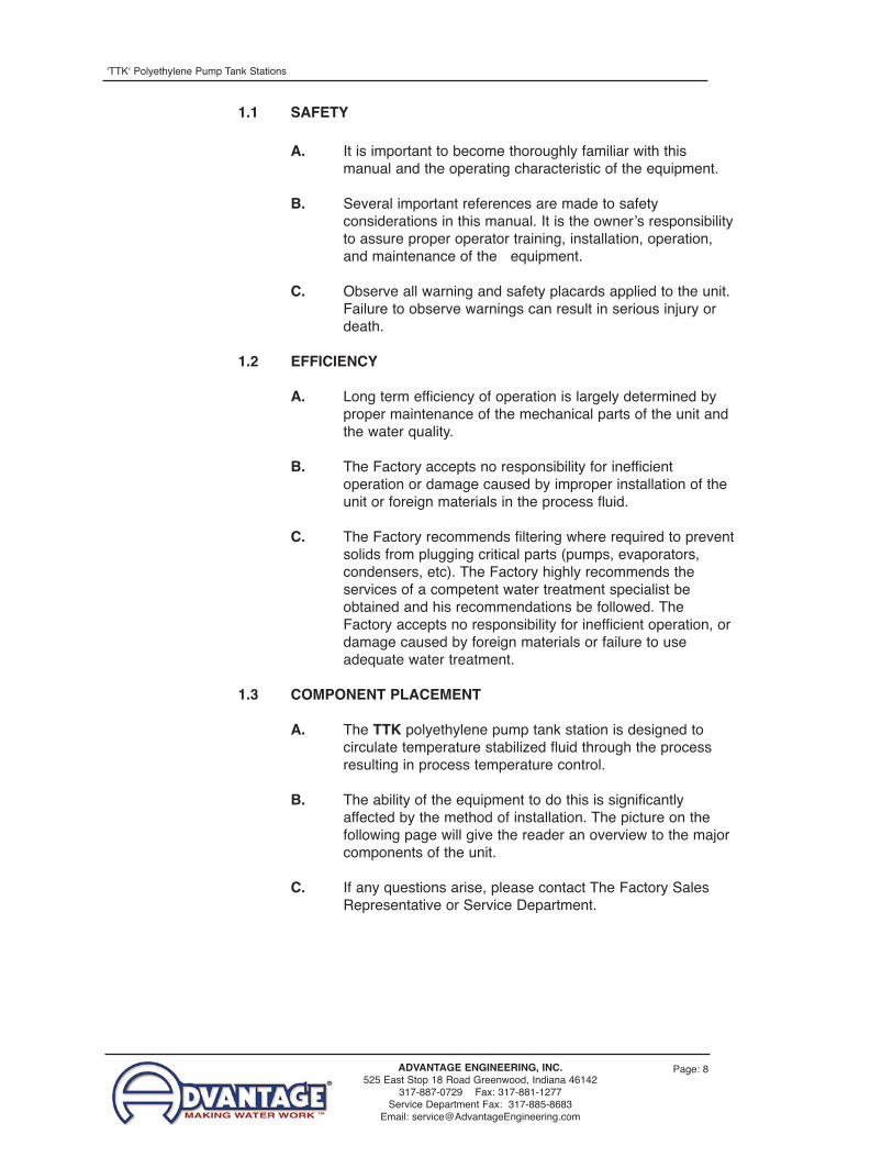
1.1 SAFETY
A. It is important to become thoroughly familiar with thismanual and the operating characteristic of the equipment.
B. Several important references are made to safetyconsiderations in this manual. It is the ownerʼs responsibilityto assure proper operator training, installation, operation,and maintenance of the equipment.
C. Observe all warning and safety placards applied to the unit.Failure to observe warnings can result in serious injury ordeath.
1.2 EFFICIENCY
A. Long term efficiency of operation is largely determined byproper maintenance of the mechanical parts of the unit andthe water quality.
B. The Factory accepts no responsibility for inefficientoperation or damage caused by improper installation of theunit or foreign materials in the process fluid.
C. The Factory recommends filtering where required to preventsolids from plugging critical parts (pumps, evaporators,condensers, etc). The Factory highly recommends theservices of a competent water treatment specialist beobtained and his recommendations be followed. TheFactory accepts no responsibility for inefficient operation, ordamage caused by foreign materials or failure to useadequate water treatment.
1.3 COMPONENT PLACEMENT
A. The TTK polyethylene pump tank station is designed tocirculate temperature stabilized fluid through the processresulting in process temperature control.
B. The ability of the equipment to do this is significantlyaffected by the method of installation. The picture on thefollowing page will give the reader an overview to the majorcomponents of the unit.
C. If any questions arise, please contact The Factory SalesRepresentative or Service Department.

Page: 9ADVANTAGE ENGINEERING, INC.525 East Stop 18 Road Greenwood, Indiana 46142
317-887-0729 Fax: 317-881-1277Service Department Fax: 317-885-8683
Email: [email protected]
ʻTTKʻ Polyethylene Pump Tank Stations
Service Lid
Alarm
Process Pump
Tower/Evaporator Pump
CheckmateTM Control Panel
Polyethylene Reservoir
Control Console
Polyethylene Tank
Sight Glass
Temperature Gauges
Alarm Beacon
Drain Valve
Pump Assembly
Pressure Gauges
Electrical Cabinet
CheckmateTM Control Panel

Page: 10
Note: this page intentionally left blank

Page: 11ADVANTAGE ENGINEERING, INC.525 East Stop 18 Road Greenwood, Indiana 46142
317-887-0729 Fax: 317-881-1277Service Department Fax: 317-885-8683
Email: [email protected]
ʻTTKʻ Polyethylene Pump Tank Stations
2.0 INSTALLATION2.1 INSTALLATION DRAWINGS2.2 PUMP BASE TO TANK MATING INSTRUCTIONS2.3 PLANT WATER DISTRIBUTION2.4 WATER BLEED (FOR TOWER SYSTEMS ONLY)2.5 VACUUM BREAKERS2.6 PROCESS CONNECTIONS2.7 WATER SUPPLY CONNECTION2.8 DRAIN AND OVERFLOW CONNECTION2.9 ELECTRICAL CONNECTION2.10 PROBE INSTALLATION

ʻTTKʻ Polyethylene Pump Tank Stations
Page: 12ADVANTAGE ENGINEERING, INC.525 East Stop 18 Road Greenwood, Indiana 46142
317-887-0729 Fax: 317-881-1277Service Department Fax: 317-885-8683
Email: [email protected]
2.1 INSTALLATION DRAWINGS
A. A number of typical drawings have been provided within this manualand with the unit. It is necessary to review all drawings supplied toassure proper installation.
B. Custom engineering drawings detailing plant water distribution areoptional. If supplied, these drawings will recommend pipe sizes,valve locations and pressure by-pass location(s) specific to yourfacility.
C. Electrical diagrams are provided based on the system design withthe unit. A typical electrical diagram have been provided within thismanual. Other electrical diagrams will be supplied as prints onrequest.
2.2 PUMP BASE TO TANK MATING INSTRUCTIONS
A. The following instructions detail the mating of the pump base to thepolyethylene tank. Refer to the drawing on the next page (figure2.2A).
B. Unless otherwise noted, all necessary parts have been supplied bythe factory.
C. Optional standby pump, alarm automatic water make-up and controlconsole are shown in the drawing. Not all systems are supplied withthese options.
D. Please note that the control console is shown ʻoff baseʼ for drawingpurposeʼs only.
E. Pump discharge manifold and sight glass are not shown in thedrawing.
F. Follow these steps to mate the pump base to the tank:
1. Slide the rubber sleeve over the pump suction ports on thetank and secure with the hose clamps.
2. Slide the loose end of the PVC pipe (with slip flange on theother end) into the empty end of the rubber sleeve andsecure with the hose clamps.
3. Align the pump base with the tank, such that the pumpsuction manifold flanges are aligned with the PVC slipflanges (as installed in step 2).
4. Mate the flanges (with the gasket in between) and bolttogether.

Page: 13ADVANTAGE ENGINEERING, INC.525 East Stop 18 Road Greenwood, Indiana 46142
317-887-0729 Fax: 317-881-1277Service Department Fax: 317-885-8683
Email: [email protected]
ʻTTKʻ Polyethylene Pump Tank Stations
Figure 2.2A
Control Console(optional)
Alarm (optional)
Level Switch Box (optional)
Standby Pump (optional)
Pump Suction Manifold
Hose ClampRubber
Tank Lid
Customer sup-plied overflowpiping
Rubber Sleeve
Hose Clamp
Overflow Port
Tough Tank
Pump Suction Port
PVC Slip Flange
Gasket
Pump BaseProcess Pump
1/2” Hose
Tower Pump

ʻTTKʻ Polyethylene Pump Tank Stations
Page: 14ADVANTAGE ENGINEERING, INC.525 East Stop 18 Road Greenwood, Indiana 46142
317-887-0729 Fax: 317-881-1277Service Department Fax: 317-885-8683
Email: [email protected]
5. Note: this step applies only if the optional water make-up system has been installed. Attach one end of the 1/2”hose to the hose barb on the bottom of the level switch boxand secure with the hose clamp. Attach the other end of the1/2” hose to the hose barb on the bottom center of the tank(see drawing) and secure with the hose clamp.
6. Slide the rubber sleeve over the overflow port and securewith the hose clamp.
7. Using either PVC with a slip flange or a pipe with no flange,slide a customer supplied overflow pipe into the other endof the rubber sleeve and secure with the hose clamp.
8. Make sure all hose clamps and bolts are fastened securely.
2.3 PLANT WATER DISTRIBUTION
A. Please note that all material used in theinstallation should be rated for 150°F and200 psi minimum. Also note that thematerials should have the equivalentdiameter or larger of their processconnections.
B. Plant water distribution system design iscritical to maximum performance of thesystem. Careful attention should be paidto the pipe sizing, length of runs, numberof elbows, tees and valving, as specified.Normally, the most successful installationsare those which insure maximum flowsand minimum pressure drops.
C. All water distribution piping should beproperly braced to prevent sway andundue stress. Brace all pipes to assure noexcess loads or strains are applied to theunit. Insulate all pipes to control excessivecondensation and to help maintain settemperature to the process (on chilled water systems).
2.4 WATER BLEED (FOR TOWER SYSTEMS ONLY)
A. It is necessary to have a water bleed-off point on all tower systems.The purpose of the water bleed-off is to purge solids whichaccumulate in the systems. See figure 2.4A for location.
B. Bleed-off rates vary depending on the geographical location of thesystem, but normally will be 2 GPM per hour per ton of tower.
Figure 2.3A

Page: 15ADVANTAGE ENGINEERING, INC.525 East Stop 18 Road Greenwood, Indiana 46142
317-887-0729 Fax: 317-881-1277Service Department Fax: 317-885-8683
Email: [email protected]
ʻTTKʻ Polyethylene Pump Tank Stations
C. The bleed-off rate can reduce significantly when water treatmentsystems are used. Consult local water treatment facilities that arefamiliar with the water quality in your area.
D. Note... never operate a tower system without the proper bleed rate.
2.5 VACUUM BREAKERS
A. Vacuum breakers (figure 2.5A) are required in all systems whereoverhead piping is used. Vacuum breakers keep the main headersystem full of fluid and prevent tank overflow during shut downperiods.
* VACUUM BREAKER IS GENERIC
FOR VACUUM RELIEF VALVE.
DRAIN - DOWN VALVE
COMMON PIPE DIAMETER THROUGHOUT
8" MIN.
VACUUM BREAK (ANTI-SIPHON)*CASH ACME MODEL #VR-801 3/4"OR EQUIVALENT

ʻTTKʻ Polyethylene Pump Tank Stations
Page: 16ADVANTAGE ENGINEERING, INC.525 East Stop 18 Road Greenwood, Indiana 46142
317-887-0729 Fax: 317-881-1277Service Department Fax: 317-885-8683
Email: [email protected]
B. The purpose of the vacuum breaker/anti-siphon (also called a drain-back dam) is to retain water in the header system during shut-downperiods and to allow for air purge which eliminates shock toplumbing during start-up.
C. It is necessary to install vacuum breakers in the ʻsupplyʼ and ʻreturnʼlines (see figure 2.4A). The vacuum breaker must be installed at thehighest point in the system, nearest to the tanks to be mosteffective. A nipple length of 8 inches minimum is required to createsufficient vacuum to open the Cash Acme model VR-801.
2.6 PROCESS CONNECTIONS
A. Connect equipment process pump dischargeport to main header supply line.
B. Connect equipment chiller ortower pump dischargeport to chiller to tower cellinlet.
C. Install return line from thechiller or tower cell intothe back 1/3 section ofthe cold tank through theprovide opening. Returnline from tower is gravityinduced flow and slopingof this pipe is critical toproper flow rates(minimum 10% slope).
D. Install ʻfrom process” lineinto the back 1/3 sectionof the hot side of the tankthrough the providedopening.
E. Note: all lines returningto the tank should extendbelow the water level,approximately 1.5 feetfrom the bottom of thetank.
F. Note: on a single pump system, the return line will connect directlyto the chiller or tower cell inlet. The line exiting out of the chiller ortower cell should be installed into the back 1/3 section of the coldside of the tank through the provided opening.
Process Connection
Tower or EvaporatorConnection
Figure 2.6A

Page: 17ADVANTAGE ENGINEERING, INC.525 East Stop 18 Road Greenwood, Indiana 46142
317-887-0729 Fax: 317-881-1277Service Department Fax: 317-885-8683
Email: [email protected]
ʻTTKʻ Polyethylene Pump Tank Stations
2.7 WATER SUPPLY CONNECTION
A. Connect the unitʼs ʻWATER SUPPLY ̓portto the plantʼs city water or well watersupply.
B. The factory recommend minimumoperating water supply pressurerequirement is identified on the unitʼs datapate. This is normally 20 psi.
C. For units with electric automatic watermake-up the water supply connection islocated on the reservoir. The make-upsolenoid valve provides the water supplyconnection.
D. For units with mechanical automatic watermake-up the water supply connection islocated on the reservoir. A bulk-head fittingattached to a float valve located inside thetank provides the water supply connection.
E. Local codes normally require a back flowprevention device be installed in the watermake-up line (customer supplied).
2.8 DRAIN and OVERFLOW CONNECTIONS:
A. Connect the drain and overflow ports tothe plantʼs drainage system. This isnormally a sanitary sewer. Consult localcodes.
Overflow connection onConventional configurations(same on Space Savingconfigurations)
Overflow connection onConventional configurations(same on Space Savingconfigurations)
Figure 2.8A
Water supplyconnection for unitswith Electrical WaterMake-Up.
Figure 2.7A
Water supplyconnection for unitswith Mechanical WaterMake-Up.
Figure 2.7B

ʻTTKʻ Polyethylene Pump Tank Stations
Page: 18ADVANTAGE ENGINEERING, INC.525 East Stop 18 Road Greenwood, Indiana 46142
317-887-0729 Fax: 317-881-1277Service Department Fax: 317-885-8683
Email: [email protected]
2.9 ELECTRICAL CONNECTION
A. Electrical power supply requirements are identified on theequipment data plate.
B. VERIFY THAT THE AVAILABLE VOLTAGE SUPPLY IS THESAME AS THE UNITʼS VOLTAGE REQUIREMENTS.
WARNING: Do not connect the unit to a voltage supply source notequal to the unitʼs voltage requirements as specified on the unitʼsdata plate. Use of incorrect voltage will void the unitʼs warranty andcause a significant hazard that may result in serious personal injuryand unit damage.
C. For units with the optional centralcontrol console... a customersupplied four conductor cable isrequired for connection to acustomer supplied fuseddisconnecting means. The fuseddisconnecting means shall be sizedand installed according to the unitʼspower supply requirements andlocal electrical codes. Connect thepower cable to the terminal L-1, L-2, L-3 and the ground lug (seefigure 2.9A). Some models may require a power supply entry holebe made in the electrical cabinet.
D. For units without the optional central control console...separate high voltage power with customer supplied disconnectingmeans is required at each motor starter. Select a four conductorcable rated for the motorʼs power requirements and install accordingto local codes. Some motor starters may require a separate 110 voltline be installed.
E. GENERAL
1. Make certain all ground connections to the unit are properlyaffixed.
2. Make certain power conductor, disconnecting means, andfusing are properly sized according to the unitʼs powersupply requirements.
3. Make certain all electrical connections are tightly affixed.Any loose wiring connections must be tighten beforeengaging the power supply.
4. Make certain no moisture or standing water is presentinside the electrical cabinet.
Typical power entry block. Figure 2.9A

Page: 19ADVANTAGE ENGINEERING, INC.525 East Stop 18 Road Greenwood, Indiana 46142
317-887-0729 Fax: 317-881-1277Service Department Fax: 317-885-8683
Email: [email protected]
ʻTTKʻ Polyethylene Pump Tank Stations
Figure 2.10B
Process Return Probe
Tower/Evaporator Return Probe
2.10 PROBE INSTALLATION
A. For systems with the CheckmateTM control panel, two probes areshipped inside the electrical cabinet and must be installed into thereturn distribution piping. These probes are encased in a threadedbulb well.
B. P2 - From Process Probe... install this probe into the from processreturn piping.
C. P4 - Tower/Evaporator Out Probe... install this probe into thereturn line from the tower or evaporator piping.
D. See the drawing (figure 2.10B) on this page for location details.
Typical shipping location for probes Figure 2.10A

Page: 20
Note: this page intentionally left blank

Page: 21ADVANTAGE ENGINEERING, INC.525 East Stop 18 Road Greenwood, Indiana 46142
317-887-0729 Fax: 317-881-1277Service Department Fax: 317-885-8683
Email: [email protected]
ʻTTKʻ Polyethylene Pump Tank Stations
3.0 OPERATIONS3.1 GENERAL3.2 START UP/OPERATIONS PROCEDURE3.3 INSTRUMENTS AND CONTROLS

ʻTTKʻ Polyethylene Pump Tank Stations
Page: 22ADVANTAGE ENGINEERING, INC.525 East Stop 18 Road Greenwood, Indiana 46142
317-887-0729 Fax: 317-881-1277Service Department Fax: 317-885-8683
Email: [email protected]
3.1 GENERAL
A. Failure to follow the factory required operation procedures mayadversely affect the unitʼs ability to adequately distribute processwater and may create a hazardous operating condition which mayresult in unit damage and serious operator injury.
B. The operator must verify that all plumbing and electricalconnections are in accordance to section 2 of this manual and localcodes.
C. The Operations segment of this manual is outlined below:
3.2 Start-up/operations procedure - follow this segment tostart the unit after the initial installation. This sectionincludes information on system fill, electric motor phasing(pump rotation) and process flow adjustments.
3.3 Instrument and controls - follow this segment to start upand operate the instrument and controls. This sectionincludes feature explanations of PTS and CPTSinstruments.
3.2 START UP / OPERATIONS
A. SYSTEM CHECKS
1. Before operating the pump tank station, verify the unitpiping installation and unit electrical installation is correct asoutlined in section 2 of this manual.
B. SYSTEM FILL
1. All systems have automatic make-up. Some havemechanical and some system use a float switch thatactivates an electric solenoid valve.
2. For units with electric automatic water make-up. Turn onplant water supply to the tank and activate power supply tothe tank. The water make-up solenoid will open and beginfilling the tank. Note: if electrical service is not connectedthe tank will not fill, manually fill the tank until the waterlevel is even with the location of the external level switchtank.
3. For units with mechanical water make-up... turn on theplant water supply to the tank. The tank will fill until thewater level reaches the make-up float.
4. For all units... when the water level has nearly reached thetop of the baffle, the unit is ready to start.

Page: 23ADVANTAGE ENGINEERING, INC.525 East Stop 18 Road Greenwood, Indiana 46142
317-887-0729 Fax: 317-881-1277Service Department Fax: 317-885-8683
Email: [email protected]
ʻTTKʻ Polyethylene Pump Tank Stations
C. VALVE PLACEMENT
1. Open to 100% thesuction valves on theprocess andtower/evaporatorpumps.
2. Open to 50% thedischarge valves onthe process andtower/evaporatorpumps.
3. Open to 100% themain ʻtoʼ and ʻfromʼprocess headervalves.
4. Open as manyprocess connectionvalves as possible toestablish a water flowpath.
D. MOTOR ROTATION FORPROCESS PUMP
1. Activate the electrical power to the unit.
2. Turn the process pump ʻonʼ momentarily and then ʻoffʼagain. Observe the shaft of each motor. As the shaft slowsto a stop, its rotation can be determined. Correct rotation isclockwise when viewed from the rear of the motor.
3. If rotation for a motor is incorrect, disconnect power andreverse any two wires at the motorʼs starter block.
E. MOTOR ROTATION FOR TOWER/EVAPORATOR PUMP ANDTOWER FAN
1. Activate the electrical power to the unit.
2. For tower system applications. It may be necessary tolower the setpoint on the Checkmate control instrument.
3. Turn the pump or fan ʻonʼ momentarily, then ʻoffʼ again.Observe the shaft of the motor. As the shaft slows to a stop,its rotation can be determined. For pump motors, correctrotation is clockwise when viewed from the rear of themotor. As for Advantage Power Tower fiberglass coolingtowers, correct rotation is counter clockwise or air should be
Suction Valve
Discharge Valve
Figure 3.2A
ʻTTKʻ Polyethylene Pump Tank Stations
Page: 24ADVANTAGE ENGINEERING, INC.525 East Stop 18 Road Greenwood, Indiana 46142
317-887-0729 Fax: 317-881-1277Service Department Fax: 317-885-8683
Email: [email protected]
drawn from the bottom of the tower and out the top. Forother tower cells, check the tower cell manual forinstructions on correct rotation.
4. If rotation for a motor is incorrect, disconnect power andreverse any two wires at the motorʼs starter block.
F. PUMP FLOW ADJUSTMENTS
1. When starting a centrifugal pump, it is important to properlyset the flow rate to prevent overloading of the pump motor.The following example is the start up procedure for a twopump system.
2. Fully open the suction valves to the process andtower/evaporator pump. Note: never allow the pumps tooperate ʻdryʼ, as this can cause shaft seal failure.
3. Close the discharge valves of the process andtower/evaporator pumps. Note: a centrifugal pump can beoperated with no flow without damage, although this shouldnot be for an extended period of time. Internal friction willcause the water in the pump case to overheat.
4. Place an amp meter on one leg of the process pump wiresat the motor starter. Start the motor. Slowly open thedischarge valve, allowing the process piping to fill withwater. After flow is established, continue to open thedischarge valve. The amp draw will increase as the flowincrease. Once the run-load amp rating, as listed on themotor data tag, is reached, leave the valve in that position.
5. Note... in initial start up, the water use points may not besufficient to fully load the motor. As you add use points, youshould recheck the amp draw on the motor and adjust thedischarge valve as needed to prevent overloading themotor.
6. Repeat the procedure with the tower/evaporator pump.
7. On tower systems... the back pressure is very low on mosttower cells. The discharge valve may only be open one ortwo notches at full load.
8. Note... never operate a centrifugal pump without water inthe case. Also, never operate a centrifugal pump withoutchecking for proper amp draw.
9. Note... always operate a centrifugal pump with the suctionvalve fully open. Adjust the amp draw with the dischargevalve starting from a closed position. Starting from a wideopen position can give a false reading and result in motor

Page: 25ADVANTAGE ENGINEERING, INC.525 East Stop 18 Road Greenwood, Indiana 46142
317-887-0729 Fax: 317-881-1277Service Department Fax: 317-885-8683
Email: [email protected]
ʻTTKʻ Polyethylene Pump Tank Stations
overload.10. Note... if during operations, the motor overload trips, the
overloads will need to be manually reset to restartoperations. Once the pump is restarted, check forexcessive motor amps at the motor start block and throttleback the discharge valve as needed.
G. PUMP TANK CYCLE
1. Two pump operation... the pump tank set is divided intotwo sections by a baffle. The sections are referred to as theʻhot sideʼ and the ʻcold sideʼ. The ʻprocess pumpʼ suction isconnected to the cold side and pumps water through thedistribution system. The water removes heat from theprocesses and returns to the hot side of the tank. Theʻevaporator pumpʼ or ʻtower pumpʼ receives water from thehot side of pumps the water through the chiller(s) ortower(s) and returns the cooled water to the cold side of thetank.
2. One pump operation... the process pump suction isconnected to the tank and pumps water through thedistribution system. The water removes heat from theprocesses and passes through the chiller(s) or tower(s).The cooled water then returns to the tank.
3. Standby pump operation... standby pumps are suppliedas an option. If installed on the system, they are suppliedvalved and wired such that switching to back-up will takeonly a few minutes. A valve orientation guide is provided insection 8 of this manual.
H. VALVE ORIENTATION FOR NORMAL AND STANDBY PUMPOPERATION
1. Refer to the following chart for proper position of the valvesfor normal and standby operations:
VALVE
Tower/Evaporator Suction Valve
Stand-By Pump (Left Side) Suction Valve
Stand-By Pump (Right Side) Suction Valve
Process Pump Suction Valve
Tower/Evaporator Discharge Valve
Manifold (Left Side) Valve
Manifold (Right Side) Valve
Process Pump Discharge Valve
Stand-ByOperation
substitute fortower/chiller pump
Stand-ByOperation
substitute fortower/chiller pump
NormalOperation
open
openopen
openopen
open
open
open
open
open
open
open
closed
closed
closed
closed
closed
closedclosed
closed
closed
closed
closedclosed

ʻTTKʻ Polyethylene Pump Tank Stations
Page: 26ADVANTAGE ENGINEERING, INC.525 East Stop 18 Road Greenwood, Indiana 46142
317-887-0729 Fax: 317-881-1277Service Department Fax: 317-885-8683
Email: [email protected]
I. TEMPERATURE AND PRESSURE GAUGES
1. Pressure gauges. The ʻto processʼ pressure gauges ismounted on the discharge side of the ʻto processʼ pump andindicates pressure to the distribution system. Theʻtower/evaporatorʼ pressure gauge is mounted on thedischarge side of the tower/evaporator pump and indicatespressure to the tower cell or chiller evaporator.
2. Temperature gauges. On systems without the digitalannunciator display, temperature gauges are mounted onboth sides of the tank. On system with the digitalannunciator display, temperature is indicated on the digitaldisplay window.
3.3 INSTRUMENT AND CONTROLS
A. INSTRUMENT AND CONTROL OPERATION
1. Determine power is supplied to the unit, (note theilluminated ʻpowerʼ led). Pressing ʻstartʼ will activate thesystem.
2. Each motor has a Top OperatorTM switch which must be ʻonʼfor the pump to activate. These switches allow for selectingprimary or standby pumps as needed. To turn off a selectedpump simply switch ʻoffʼ the pump. Press ʻstopʼ to shutdown the system. Pressing ʻstopʼ will deactivate all pumpsthat have been switched ʻonʼ by their individual toggles.
3. Each pump is controlled by dedicated motor starters. Toactivate the pump, press ʻstartʼ. To deactivate the pump,press ʻstopʼ.
Typical pressure gauge set up onsystem with the conventionalconfiguration (to process pressuregauge shown).
Typical temperature gauge setup on system without thedigital annunciator panel
Page: 27ADVANTAGE ENGINEERING, INC.525 East Stop 18 Road Greenwood, Indiana 46142
317-887-0729 Fax: 317-881-1277Service Department Fax: 317-885-8683
Email: [email protected]
ʻTTKʻ Polyethylene Pump Tank Stations
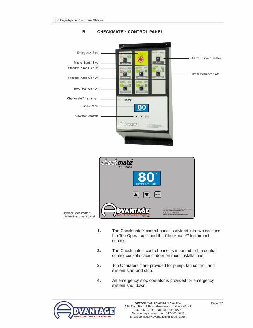
B. CHECKMATETM CONTROL PANEL
1. The CheckmateTM control panel is divided into two sections:the Top OperatorsTM and the CheckmateTM instrumentcontrol.
2. The CheckmateTM control panel is mounted to the centralcontrol console cabinet door on most installations.
3. Top OperatorsTM are provided for pump, fan control, andsystem start and stop.
4. An emergency stop operator is provided for emergencysystem shut down.
Master Start / Stop
Emergency Stop
Process Pump On / Off
Standby Pump On / Off
CheckmateTM Instrument
Display Panel
Operator Controls
Tower Fan On / Off
Alarm Enable / Disable
Tower Pump On / Off
Typical CheckmateTM
control instrument panel

ʻTTKʻ Polyethylene Pump Tank Stations
Page: 28ADVANTAGE ENGINEERING, INC.525 East Stop 18 Road Greenwood, Indiana 46142
317-887-0729 Fax: 317-881-1277Service Department Fax: 317-885-8683
Email: [email protected]
C. TOP OPERATORTM OPERATION FOR PUMP CONTROL
1. To start the pump turn the switch to“ON”.
2. To stop the pump turn the switch to“OFF”.
3. Normal pump operation is indicated bythe “GREEN” light. Overload conditionis indicated by a “RED” light.
D. TOP OPERATORTM OPERATION FOR TOWER FAN CONTROL
1. To start the fan turn the switch to “ON”.
2. To stop the pump turn the switch to“OFF”.
3. To auto control the tower fan turn theswitch to “AUTO”. The fan will becontrolled by the system instrument.
4. Normal fan operation is indicated by the “GREEN” light.Overload condition is indicated by a “RED” light.
E. CHECKMATETM INSTRUMENT OPERATION
1. System information is displayed in the center screen. Usethe “SELECT” button to scroll through the different screens.Use the “UP” or “DOWN” arrow buttons to set differentoperational parameters.
2. MAIN SCREEN. Displaysthe current To Processtemperature in °F. Thesetpoint temperature is alsodisplayed.
3. TEMPERATURE STATUSSCREEN. Displays theFrom Process, To Processand From Towertemperatures. On chilledwater installations, there isa From Chiller displayinstead of the From Towerdisplay (as shown in thephoto).
PROCESS
STATUS
84 94
TO FROM
TOWER 94
84
Temperature Status Screen
84SETPOINT 84
°F
Main Screen

Page: 29ADVANTAGE ENGINEERING, INC.525 East Stop 18 Road Greenwood, Indiana 46142
317-887-0729 Fax: 317-881-1277Service Department Fax: 317-885-8683
Email: [email protected]
ʻTTKʻ Polyethylene Pump Tank Stations
4. PROCESS PUMP STATUSSCREEN. Displays the on /off status of the processpumps.
5. CONTROL STATUSSCREEN. Display the on /off status of the fans andprocess pumps.
6. SETUP SCREENS. Theoperator can select thisscreen to enter the SetpointTemperature, the Hi Alarmand Low Alarm values. TheHi Alarm value is thenumber of degree abovethe setpoint when the alarmwill sound. The Lo Alarmtemperature is the numberof degrees below thesetpoint when the alarm willsound.
7. ALARM SCREENS.Displays the date, time andreason of system errors
8. SYSTEM TIME SCREENS.Display the running hours of the process, standby, and tower pump and fan(s).
E. ALARM SYSTEM OPERATION
1. The audible / visual alarmsystem is an optionalcomponent. If installed,there is a visual and audiblealarm beacon mounted onthe control cabinet (typical).There are three types ofalarms, the alarm log willindicate the type of faultactivating the alarm output.
2. Low pump pressure... theʻto processʼ pressure fallsbelow the pressure switchsetting. The default is 40PSI to open the contactsand 20 PSI to close the
PRESSURE 15LEVEL 4
DELAYS
PUMP 1
PROCESS PUMPS
ON 17PUMP 2 OFF 13
Process Pump Status Screen
1 PUMP
OUTPUTS
ON 172 FAN ON 173 FAN ON 174 ON 175 ON 176 ON 17
Control Status Screen
PRESS 5
TO ENTER
SETUP ACCESS
PROCESS 84HI ALARM 20LO ALARM 20
SETPOINTS
PUMP 5FAN 5
CONTROL OFFSET
OUTPUT 1 PUMP
CONFIGURE 1
OUTPUT 2 FANOUTPUT 3 FANOUTPUT 4 OUTPUT 5 OUTPUT 6
Setup Screens (5 of 5)

ʻTTKʻ Polyethylene Pump Tank Stations
Page: 30ADVANTAGE ENGINEERING, INC.525 East Stop 18 Road Greenwood, Indiana 46142
317-887-0729 Fax: 317-881-1277Service Department Fax: 317-885-8683
Email: [email protected]
YEAR 07MONTH 11DAY 30HOUR 12MIN 24
SET TIME
11-23-07 14:13
PRESS 5
TO ENTER
SYSTEM TIME
System Time Screens (2 of 2)
contacts and trigger thealarm).
Causes of low pumppressure are: pump notoperating due to trippedoverloads; impellerdamaged or some internalpump obstruction;excessive gpm.
3. Low water level... the lowwater level alarm can beadjusted from 1 - 30 minutes.If you set to 0, the alarm isdisable.
Possible causes: defectivemakeup solenoid, defectivelevel switch, makeup watersupply insufficient.
PRESS 5
TO ENTER
ALARM LOG
11-23-07 14:13
SETPOINT 78PROCESS 78
SYSTEM RESET
ALARM LOG
Alarm Log Screens (2 of 2)

Page: 31ADVANTAGE ENGINEERING, INC.525 East Stop 18 Road Greenwood, Indiana 46142
317-887-0729 Fax: 317-881-1277Service Department Fax: 317-885-8683
Email: [email protected]
ʻTTKʻ Polyethylene Pump Tank Stations
SEL
SEL
SEL
SEL
SEL
SEL
SEL
SEL
SEL
SEL
SEL
SEL
SEL
Setpoints
Config 1
Delays
Communication
System Config
SEL
SYSTEM CONFIG
ADRESS 1RATE 1
COMMUNICATION
PRESSURE 15LEVEL 4
DELAYS
OUTPUT 1 PUMP
CONFIGURE 1
OUTPUT 2 FANOUTPUT 3 FANOUTPUT 4 OUTPUT 5 OUTPUT 6
PROCESS 84ALT SP 40HI ALARM 20LO ALARM 20
SETPOINTS
PRESS �
TO ENTER
ALARM LOG
11-23-07 14:13
SETPOINT 78PROCESS 78
SYSTEM RESET
ALARM LOG
YEAR 07MONTH 11DAY 30HOUR 12MIN 24
SET TIME
11-23-07 14:13
PRESS �
TO ENTER
SYSTEM TIME
PRESS �
TO ENTER
SETUP ACCESS
PROCESS
STATUS
84 94
TO FROM
TOWER 94
84
PUMP 1
PROCESS PUMPS
ON 17PUMP 2 OFF 13
1 PUMP
OUTPUTS
ON 172 FAN ON 173 FAN ON 174 ON 175 ON 176 ON 17
84SETPOINT 84
°F
RANGE 1 to 99
TYPE 1
1 - PTS2 - CPTS

Page: 32
Note: this page intentionally left blank

Page: 33ADVANTAGE ENGINEERING, INC.525 East Stop 18 Road Greenwood, Indiana 46142
317-887-0729 Fax: 317-881-1277Service Department Fax: 317-885-8683
Email: [email protected]
ʻTTKʻ Polyethylene Pump Tank Stations
4.0 MAINTENANCE4.1 PREVENTIVE MAINTENANCE4.2 PUMP SEAL SERVICE4.3 SOLENOID VALVE SERVICE4.4 INSTRUMENT CALIBRATION

ʻTTKʻ Polyethylene Pump Tank Stations
Page: 34ADVANTAGE ENGINEERING, INC.525 East Stop 18 Road Greenwood, Indiana 46142
317-887-0729 Fax: 317-881-1277Service Department Fax: 317-885-8683
Email: [email protected]
4.1 PREVENTIVE MAINTENANCE
A. The following is a guide to preventive maintenance. The frequencyof maintenance will vary with each application, installationconditions, flow rates, hours of use and operating temperatures.
B. Preventive maintenance:
1. Lubricate all motors. Note: some motors are supplied withsealed bearings.
2. Tighten all wire terminations.
3. Clean and check motor starter and contactor contacts.
4. Check safety switch settings (ie. alarm thermostat).
5. Check all motors for correct amperage.
6. Clean water make-up solenoid valve.
7. Clean and flush unit.

Page: 35ADVANTAGE ENGINEERING, INC.525 East Stop 18 Road Greenwood, Indiana 46142
317-887-0729 Fax: 317-881-1277Service Department Fax: 317-885-8683
Email: [email protected]
ʻTTKʻ Polyethylene Pump Tank Stations
4.2 PUMP SEAL REPLACEMENT
A. The unit pump seal is a carbon/niresist shaft seal assemblyincluding a stationary member, rotating member and tension spring(figure 4.2A).
B. The operator can determine the pump seal is leaking when fluid isidentified leaking from the pump case adapter.
C. Generally, a pump seal will leak due to inadequate unit pressure,excessive flow and poor fluid quality.
D. The operator should follow this procedure to replace the pump seal:
1. Disengage process operations. The operator must becertain process fluid pressure is relieved (pressure gaugereads “0”) and water system flow is shut off and all pressurerelieved.
2. Disengage main power supply. The operator must verify thePOWER light on the display is off.
3. Close the suction and discharge valves.
4. Drain pump. The pump can be drained by using the drainplug located on the pump case.
5. Locate and remove thethree motor wire leads fromthe motor wiring terminals.The operator should “map”the wire terminal locationsto ensure correct rewiring.The power cord should beremoved from the motorhousing (figure 4.2B).
6. Locate and remove thepump casing bolts. Thesebolts secure the motor andmotor adapter to the pumpcasing (figure 4.2C).
7. Separate the motor andmotor adapter from thepump casing to expose thepump impeller (figure4.2D). Remove the motorand motor adapter from theunit and place on aworkbench to continue theprocedure.
Motor leads Figure 4.2B
Pump casing bolts Figure 4.2C

ʻTTKʻ Polyethylene Pump Tank Stations
Page: 36ADVANTAGE ENGINEERING, INC.525 East Stop 18 Road Greenwood, Indiana 46142
317-887-0729 Fax: 317-881-1277Service Department Fax: 317-885-8683
Email: [email protected]
8. Locate and remove thedust cap from motor end toexpose slotted motor shaft.The motor shaft is free torotate, but must be securedto remove the impeller. Tosecure the motor shaft,insert a flat bladed screwdriver in slot to hold theshaft stationary (Figure4.2E).
9. Locate and removeimpeller locking screw(Figure 4.2F). Using asocket and ratchet, theimpeller retaining screwcan be removed. Once theretaining screw is removed,the impeller can be“unthreaded” from themotor shaft to expose thepump seal assembly.
10. Remove all seal parts(Figure 4.2G). Note sealcomponent arrangement tofacilitate reassembly.
11. Clean motor shaft andlubricate with a mild soapsolution.
12. Install new stationary sealmember in pump casingcavity (figure 4.2H). Theoperator must be certainthe stationary seal memberis fully squared and seatedin cavity.
13. Slide the rotating memberonto the lubricated pumpshaft (figure 4.2I). Theoperator must be certainnot to damage or tear therubber bellows assembly.
14. Place the spring onto therotating member.
Removing impeller lockingscrew with ratchet
Figure 4.2F
Seal components Figure 4.2G
Impeller Figure 4.2D
Motor shaft Figure 4.2E

Page: 37ADVANTAGE ENGINEERING, INC.525 East Stop 18 Road Greenwood, Indiana 46142
317-887-0729 Fax: 317-881-1277Service Department Fax: 317-885-8683
Email: [email protected]
ʻTTKʻ Polyethylene Pump Tank Stations
15. Align the impeller, springand rotating memberbefore reinstalling theimpeller (figure 4.2J). Theoperator must be certainthe spring and rotatingmember are aligned beforethe impeller is fully tightenand the impeller retainingscrew is reinstalled.
16. Clean pump casing,cavities, impeller and O-ring before reassembly.
17. Mate the motor and motoradapter to the pumpcasing. Reinstall the pumpcasing bolts.
18. Reconnect the watercooling lines to the pumpadapter (if applicable).
19. Reconnect the motor powercord and leads.
20. Restore all cover panels aswere removed.
E. When the pump seal replacementprocedure is complete, the operatormay restart the unit according thesection 3. In some cases, a newpump seal will experience a smallamount of leakage for a short time.This is normal. After operating afew moments, the new seal will take action and the leak will stop.
Aligning impeller and spring Figure 4.2J
Stationary member Figure 4.2H
Rotating member Figure 4.2I

ʻTTKʻ Polyethylene Pump Tank Stations
Page: 38ADVANTAGE ENGINEERING, INC.525 East Stop 18 Road Greenwood, Indiana 46142
317-887-0729 Fax: 317-881-1277Service Department Fax: 317-885-8683
Email: [email protected]
4.3 SOLENOID VALVE SERVICE
A. Units with the optional electric water make-up system use asolenoid valve controlled by the float switch for water make-up.
B. The operator can determine the solenoid valve requires servicewhen the tank does not ʻmake-upʼ as required.
C. Generally, solenoid valves fail due to poor water quality, low waterflow, or defective valve elements.
D. The operator should follow this procedure to service the coolingsolenoid valve:
1. Disengage main power supply. The operator must verify thePOWER light on the display is “off”.
2. The operator must be certain all water system pressure isrelieved from the supply line.
3. If necessary, remove or open any access cover panel andset aside to gain access to the solenoid valve.
4. Identify the retaining screw (figure 4.3A) on the solenoidvalve coil. Remove the screw. Keeping all electricalconnections intact, lift the coil off of the enclosure tube andset aside.
5. Use a pair of channel lockpliers or a pipe wrench toseparate the bonnetassembly from the valvebody. The plunger is“loose” inside the enclosingtube. Be certain it isretained in the enclosuretube as the bonnet isremoved (figure 4.3B).
6. Identify the diaphragmassembly. Gently removethe assembly from thevalve body (figure 4.3C).
7. Identify the mesh screen.Gently removed the meshscreen and clean orreplace as necessary.Clean the valve body.
Coil Figure 4.3A
Retaining screw
Top bonnet Figure 4.3BEnclosure tube
Plunger Diaphragm assembly

Page: 39ADVANTAGE ENGINEERING, INC.525 East Stop 18 Road Greenwood, Indiana 46142
317-887-0729 Fax: 317-881-1277Service Department Fax: 317-885-8683
Email: [email protected]
ʻTTKʻ Polyethylene Pump Tank Stations
8. Reset the mesh screen intothe valve body.
9. If a new diaphragmassembly was obtained,continue with step 11. Ifnot, disassemble thediaphragm assembly andnote component order(figure 4.3D). Clean thevalve port, plate, collar andO-ring. Once cleaned,reassemble the diaphragm.
10. Set the reassembleddiaphragm assembly intothe valve body. The stemshould be facing out of thevalve body.
11. Inset the plunger withspring first into theenclosing tube of the topbonnet (figure 4.3E).Holding the plunger in theenclosure tube, set the topbonnet onto the valve bodyand tighten.
12. Place the coil onto the topbonnet and replace theretaining screw.
13. Open the water supplyvalve (if installed) tocirculate water. Restartthe unit.
Figure 4.3CO-Ring
Diaphragm assembly Mesh screen
Figure 4.3EPlungerSpring
Top bonnet Enclosure tube
Figure 4.3DO-RingDiaphragm and stem
Collar Plate
ʻTTKʻ Polyethylene Pump Tank Stations
Page: 40ADVANTAGE ENGINEERING, INC.525 East Stop 18 Road Greenwood, Indiana 46142
317-887-0729 Fax: 317-881-1277Service Department Fax: 317-885-8683
Email: [email protected]
4.4 DISPLAY CALIBRATION
A. The temperature is sent to the instrument by sensor probesmounted throughout the unit. These probes are temperaturetransducers embedded into a threaded well. The transducerconverts temperature changes into a proportional current output.The display circuitry converts the information into a digital display.
B. Consult the Service Department for calibration of the instrument at317-887-0729.

Page: 41ADVANTAGE ENGINEERING, INC.525 East Stop 18 Road Greenwood, Indiana 46142
317-887-0729 Fax: 317-881-1277Service Department Fax: 317-885-8683
Email: [email protected]
ʻTTKʻ Polyethylene Pump Tank Stations
5.0 RELATED DRAWINGS5.1 ELECTRICAL

ʻTTKʻ Polyethylene Pump Tank Stations
Page: 42ADVANTAGE ENGINEERING, INC.525 East Stop 18 Road Greenwood, Indiana 46142
317-887-0729 Fax: 317-881-1277Service Department Fax: 317-885-8683
Email: [email protected]
5.1 ELECTRICAL
A. A specific electrical drawing has been prepared for your system.The drawing is generally included with manual.
B. If you need a copy of your electrical drawing, contact the ServiceDepartment at 317-887-0729. You will need your model and serialnumbers to obtain the proper drawing.
Page: 43ADVANTAGE ENGINEERING, INC.525 East Stop 18 Road Greenwood, Indiana 46142
317-887-0729 Fax: 317-881-1277Service Department Fax: 317-885-8683
Email: [email protected]
ʻTTKʻ Polyethylene Pump Tank Stations
6.0 APPENDIX6.1 TYPICAL PRESS DROP

ʻTTKʻ Polyethylene Pump Tank Stations
Page: 44ADVANTAGE ENGINEERING, INC.525 East Stop 18 Road Greenwood, Indiana 46142
317-887-0729 Fax: 317-881-1277Service Department Fax: 317-885-8683
Email: [email protected]
6.1 TYPICAL PRESS DROP
The design of the unit-to-process hook up is key to optimizing the capability of theheating/cooling system. Selecting proper pipe IDʼs, minimum run lengths, minimum elbows,tees, etc. are all important to creating a low pressure drop... thus a high flow rate...installation.
This diagram schematically contains piping and valving details which may not be needed inall cases. However, for molding installations requiring maximum flexibility, a relatively minorincrease in original piping costs can have great efficiency paybacks in the future.
Select pipe sizes for 5-7 feet per second flow velocity and 5-10 psi pressure drop. Consultengineering department for assistance when needed.
KEYTWS - Tower Water SupplyTWR - Tower Water ReturnCWS - Chilled Water Supply*CWR - Chilled Water Return*
*INSULATE ALL CHILLED WATER PIPING
TWSTWRCWSCWR
TWR CWR
TWS CWS
To/fromAuxiliary Unit
To/from Auxiliary Unit
To/fromAuxiliary Unit
Temperature and pressure gaugescheck system performance
Note: for many processes, watermanifolds are desirable at this location
Water Regulator Valve
HydraulicHeat Exchanger
Mold - Roll
or other process
To/fromAuxiliary Unit
TWSTWRCWSCWR
1 3
4
5 6 7 8
9
10
11
12
13 14
18 17 15 16
19 20
2
VALVE POSITIONTower supply for auxiliary Open: 1 - 2Chilled water for auxiliary Open: 3 - 4Tower on mold Open: 5 - 6 - 9 - 10 - 11 - 12Chilled water on mold Open: 7 - 8 - 11 - 12Auxiliary on mold Open: 13 - 14Tower on heat exchanger Open: 5 - 6 - 17 - 18Chilled water on heat exchanger Open: 7 - 8 - 15 - 16Auxiliary on heat exchanger Open: 19 - 20

END© 2013 ADVANTAGE ENGINEERING, INC.
RE 8 02/07/2013