Embed Size (px)
Citation preview
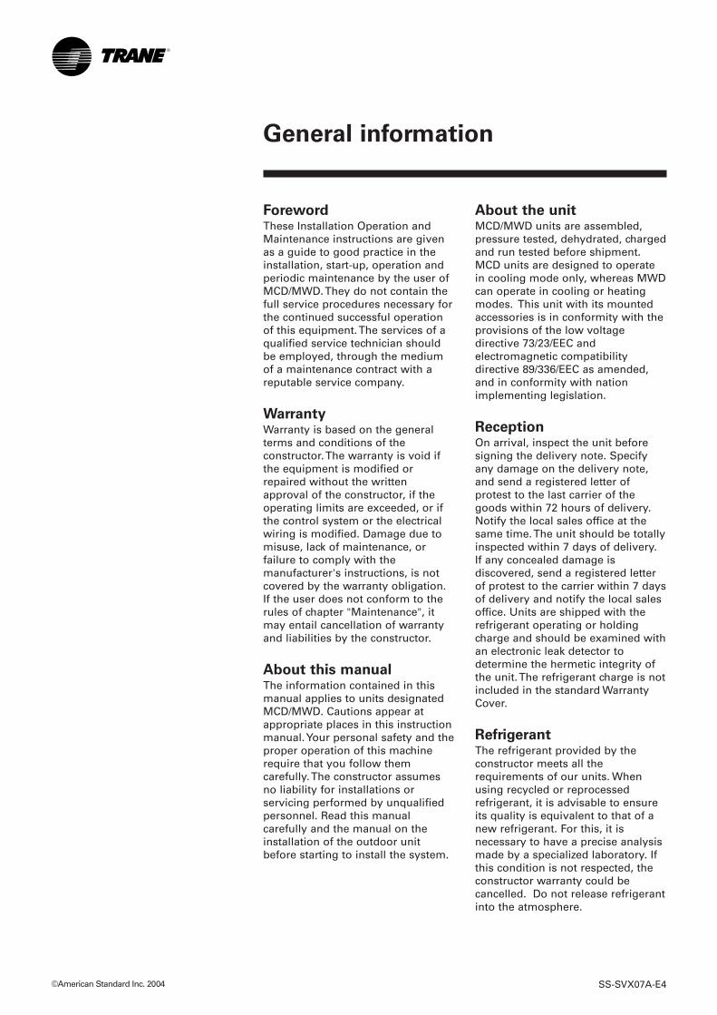
Installation
Operation
Maintenance
MCD/MWD
512-518-524-530-536-048-060
Ductable ceiling-suspended unit
SS-SVX07A-E4
About the unitMCD/MWD units are assembled,pressure tested, dehydrated, chargedand run tested before shipment.MCD units are designed to operatein cooling mode only, whereas MWDcan operate in cooling or heatingmodes. This unit with its mountedaccessories is in conformity with theprovisions of the low voltagedirective 73/23/EEC andelectromagnetic compatibilitydirective 89/336/EEC as amended,and in conformity with nationimplementing legislation.
ReceptionOn arrival, inspect the unit beforesigning the delivery note. Specifyany damage on the delivery note,and send a registered letter ofprotest to the last carrier of thegoods within 72 hours of delivery.Notify the local sales office at thesame time. The unit should be totallyinspected within 7 days of delivery.If any concealed damage isdiscovered, send a registered letterof protest to the carrier within 7 daysof delivery and notify the local salesoffice. Units are shipped with therefrigerant operating or holdingcharge and should be examined withan electronic leak detector todetermine the hermetic integrity ofthe unit. The refrigerant charge is notincluded in the standard WarrantyCover.
RefrigerantThe refrigerant provided by theconstructor meets all therequirements of our units. Whenusing recycled or reprocessedrefrigerant, it is advisable to ensureits quality is equivalent to that of anew refrigerant. For this, it isnecessary to have a precise analysismade by a specialized laboratory. Ifthis condition is not respected, theconstructor warranty could becancelled. Do not release refrigerantinto the atmosphere.
ForewordThese Installation Operation andMaintenance instructions are givenas a guide to good practice in theinstallation, start-up, operation andperiodic maintenance by the user ofMCD/MWD. They do not contain thefull service procedures necessary forthe continued successful operationof this equipment. The services of aqualified service technician shouldbe employed, through the mediumof a maintenance contract with areputable service company.
WarrantyWarranty is based on the generalterms and conditions of theconstructor. The warranty is void ifthe equipment is modified orrepaired without the writtenapproval of the constructor, if theoperating limits are exceeded, or ifthe control system or the electricalwiring is modified. Damage due tomisuse, lack of maintenance, orfailure to comply with themanufacturer's instructions, is notcovered by the warranty obligation.If the user does not conform to therules of chapter "Maintenance", itmay entail cancellation of warrantyand liabilities by the constructor.
About this manualThe information contained in thismanual applies to units designatedMCD/MWD. Cautions appear atappropriate places in this instructionmanual. Your personal safety and theproper operation of this machinerequire that you follow themcarefully. The constructor assumesno liability for installations orservicing performed by unqualifiedpersonnel. Read this manualcarefully and the manual on theinstallation of the outdoor unitbefore starting to install the system.
©American Standard Inc. 2004 SS-SVX07A-E4
General information
SS-SVX07A-E4 3
Contents
General information
Foreword 2Warranty 2General information 2Reception 2Refrigerant 2
Installation
Before starting 4General data 5Operating limits 13Power and control wiring 14Choice of installation position 15Refrigerant connections 16Condensate connections 18Electrical connections 18Connecting the ducts 19Filtering 19Installing the wired controller 19
Operation
Creating a vacuum 20Additional refrigerant charge 20Fan speed 21Configuration and operation 21Before start-up by a qualified technician 21Unit display and emergency switch operation 21Wired controller operation 21Wireless controller operation 21
Maintenance
Periodic maintenance 23Troubleshooting 24Controller troubleshooting 26Safety recommendations 28Maintenance contract 28Training 28
4 SS-SVX07A-E4
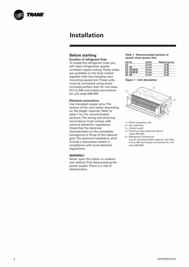
Before startingCreation of refrigerant lines
To create the refrigerant lines youwill need refrigeration qualityannealed copper tubing. These tubesare available on the local markettogether with the insulation andmounting equipment. These unitsmust be connected using screwconnections/flare type for unit sizes512 to 536 and brazed connectionsfor unit sizes 048-060.
Electrical connections
Use insulated copper wire. Thesection of the core varies dependingon the length required. Refer totable 1 for the recommendedsections. The wiring and electricalconnections must comply withnational electricity regulations.Check that the electricalcharacteristics on the nameplatecorrespond to those of the nationalgrid. The electrical installation shallinclude a disconnect switch incompliance with local electricalregulations.
WARNING!
Never open the indoor or outdoorunit without first disconnecting thepower supply. There is a risk ofelectrocution.
Table 1 - Recommended sections of
electric wires (power link)
Unit size Section Maximum fuse size512 2.5 mm² 16 aM518 - 524 2.5 mm² 32 aM530 - 536 RB/SB 4.0 mm² 40 aM530 - 536 RB/SB 2.5 mm² 32 aM048 - 060 2.5 mm² 32 aM
Figure 1 - Unit description
1 = Direct expansion coil2 = Fan assembly3 = Control panel4 = Cooling mode expansion device
(sizes 530-060)5 = Refrigerant connections
(screw connections/flare type for unit sizes512 to 536 and brazed connections for unitsizes 048-060)
▲
1
2
3
5
4
Installation
SS-SVX07A-E4 5
Installation
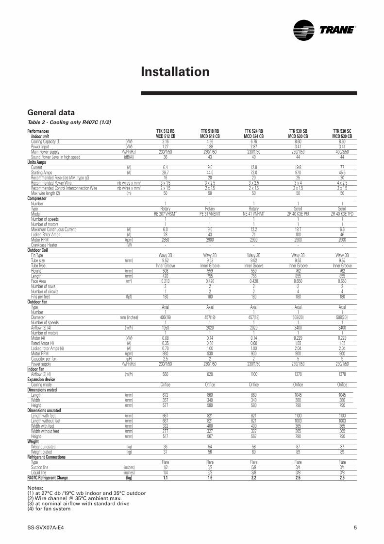
General dataTable 2 - Cooling only R407C (1/2)
Performances TTK 512 RB TTK 518 RB TTK 524 RB TTK 530 SB TTK 530 SCIndoor unit MCD 512 CB MCD 518 CB MCD 524 CB MCD 530 CB MCD 530 CBCooling Capacity (1) (kW) 3.16 4.56 6.76 8.60 8.60Power Input (kW) 1.27 1.88 2.87 3.41 3.41Main Power supply (V/Ph/Hz) 230/1/50 230/1/50 230/1/50 230/1/50 400/3/50Sound Power Level in high speed (dB(A)) 36 43 40 44 44
Units AmpsCurrent (A) 6.4 9.6 12.8 19.8 7.7Starting Amps (A) 28.7 44.0 72.0 97.0 45.5Recommended Fuse size (AM) type gG 16 20 20 25 20Recommended Power Wire nb wires x mm2 3 x 1.5 3 x 2.5 3 x 2.5 3 x 4 4 x 2.5Recommended Control Interconnection Wire nb wires x mm2 2 x 1.5 2 x 1.5 2 x 1.5 2 x 1.5 2 x 1.5Max wire length (2) (m) 50 50 50 50 50
CompressorNumber 1 1 1 1 1Type Rotary Rotary Rotary Scroll ScrollModel RE 207 VHSMT PE 31 VNEMT NE 41 VNHMT ZR 40 K3E PFJ ZR 40 K3E TFDNumber of speeds 1 1 1 1 1Number of motors 1 1 1 1 1Maximum Continuous Current (A) 6.0 9.0 12.2 18.7 6.6Locked Rotor Amps (A) 28 43 71 100 46Motor RPM (rpm) 2850 2900 2900 2900 2900Crankcase Heater (W) - - - - -
Outdoor CoilFin Type Wavy 3B Wavy 3B Wavy 3B Wavy 3B Wavy 3BTube size (mm) 9.52 9.52 9.52 9.52 9.52Tube Type Inner Groove Inner Groove Inner Groove Inner Groove Inner GrooveHeight (mm) 508 559 559 762 762Length (mm) 420 755 755 855 855Face Area (m2) 0.213 0.420 0.420 0.650 0.650Number of rows 2 2 2 2 2Number of circuits 1 2 2 4 4Fins per feet (fpf) 180 180 180 180 180
Outdoor FanType Axial Axial Axial Axial AxialNumber 1 1 1 1 1Diameter mm (inches) 406(16) 457(18) 457(18) 508(20) 508(20))Number of speeds 1 1 1 1 1Airflow (3) (4) (m3/h) 1050 2020 2020 3400 3400Number of motors 1 1 1 1 1Motor (4) (kW) 0.08 0.14 0.14 0.229 0.229Rated Amps (4) (A) 0.35 0.60 0.60 1.05 1.05Locked rotor Amps (4) (A) 0.70 1.00 1.00 2.04 2.04Motor RPM (rpm) 930 930 930 900 900Capacitor per fan (µF) 2.5 2 2 5 5Power supply (V/Ph/Hz) 230/1/50 230/1/50 230/1/50 230/1/50 230/1/50
Indoor FanAirflow (3) (4) (m3/h) 550 820 1100 1370 1370
Expansion deviceCooling mode Orifice Orifice Orifice Orifice Orifice
Dimensions cratedLength (mm) 672 860 860 1045 1045Width (mm) 357 340 340 380 380Height (mm) 577 580 580 790 790
Dimensions uncratedLength with feet (mm) 667 821 821 1100 1100Length without feet (mm) 667 821 821 1003 1003Width with feet (mm) 332 400 400 365 365Width without feet (mm) 277 327 327 365 365Height (mm) 517 567 567 790 790
WeightWeight uncrated (kg) 36 54 58 87 87Weight crated (kg) 37 56 60 89 89
Refrigerant ConnectionsType Flare Flare Flare Flare FlareSuction line (inches) 1/2 5/8 5/8 3/4 3/4Liquid line (inches) 1/4 3/8 3/8 3/8 3/8
R407C Refrigerant Charge (kg) 1.1 1.6 2.2 2.5 2.5
Notes:(1) at 27°C db /19°C wb indoor and 35°C outdoor(2) Wire channel @ 35°C ambient max.(3) at nominal airflow with standard drive(4) for fan system

6 SS-SVX07A-E4
Installation
Table 2 - Cooling only R407C (2/2)
Performances TTK 536 SB TTK 536 SC TTK 048 SC TTK 060 SCIndoor unit MCD 536 CB MCD 536 CB MCD 048 CB MCD 060 CBCooling Capacity (1) (kW) 9.42 9.42 13.14 14.90Power Input (kW) 4.35 4.35 5.25 6.37Main Power supply (V/Ph/Hz) 230/1/50 400/3/50 400/3/50 400/3/50Sound Power Level in high speed (dB(A)) 44 44 53 63
Units AmpsCurrent (A) 24.6 11.1 11.3 12.7Starting Amps (A) 116.0 52.0 64.0 72.5Recommended Fuse size (AM) type gG 40 20 20 20Recommended Power Wire nb wires x mm2 3 x 6 4 x 2.5 4 x 2.5 4 x 2.5Recommended Control Interconnection Wire nb wires x mm2 2 x 1.5 2 x 1.5 2 x 1.5 2 x 1.5Max wire length (2) (m) 50 50 50 50
CompressorNumber 1 1 1 1Type Scroll Scroll Scroll ScrollModel ZR 48 K3E PFJ ZR 48 K3E TFD ZR 61 KCE TFD ZR 72 KCE TFDNumber of speeds 1 1 1 1Number of motors 1 1 1 1Maximum Continuous Current (A) 23.5 10.0 10.0 11.4Locked Rotor Amps (A) 114 50 65.5 74Motor RPM (rpm) 2900 2900 2900 2900Crankcase Heater (W) - - - -
Outdoor CoilFin Type Wavy 3B Wavy 3B Wavy 3B Wavy 3BTube size (mm) 9.52 9.52 9.52 9.52Tube Type Inner Groove Inner Groove Inner Groove Inner GrooveHeight (mm) 762 762 1219 1219Length (mm) 855 855 855 855Face Area (m2) 0.650 0.650 1.048 1.048Number of rows 2 2 2 2Number of circuits 4 4 6 6Fins per feet (fpf) 180 180 240 240
Outdoor FanType Axial Axial Axial AxialNumber 1 1 2 2Diameter mm (inches) 508(20) 508(20) 457(18) 457(18)Number of speeds 1 1 1 1Airflow (3) (4) (m3/h) 3400 3400 4600 4600Number of motors 1 1 2 2Motor (4) (kW) 0.229 0.229 0.29 0.29Rated Amps (4) (A) 1.05 1.05 1.20 1.20Locked rotor Amps (4) (A) 2.04 2.04 2.00 2.00Motor RPM (rpm) 900 900 930 930Capacitor per fan (µF) 5 5 4 4Power supply (V/Ph/Hz) 230/1/50 230/1/50 230/1/50 230/1/50
Indoor FanAirflow (3) (4) (m3/h) 1650 1650 2190 2300
Expansion deviceCooling mode Orifice Orifice Orifice Orifice
Dimensions cratedLength (mm) 1045 1045 1045 1045Width (mm) 380 380 390 390Height (mm) 790 790 1389 1389
Dimensions uncratedLength with feet (mm) 1100 1100 1030 1030Length without feet (mm) 1003 1003 1030 1030Width with feet (mm) 365 365 420 420Width without feet (mm) 365 365 366 366Height (mm) 790 790 1246 1246
WeightWeight uncrated (kg) 89 89 105 108Weight crated (kg) 91 91 108 111
Refrigerant ConnectionsType Flare Flare Braze BrazeSuction line (inches) 3/4 3/4 1 1/8 1 1/8Liquid line (inches) 3/8 3/8 3/8 3/8
R407C Refrigerant Charge (kg) 2.5 2.5 3.8 4.2
Notes:(1) at 27°C db /19°C wb indoor and 35°C outdoor(2) Wire channel @ 35°C ambient max.(3) at nominal airflow with standard drive(4) for fan system
SS-SVX07A-E4 7
Installation
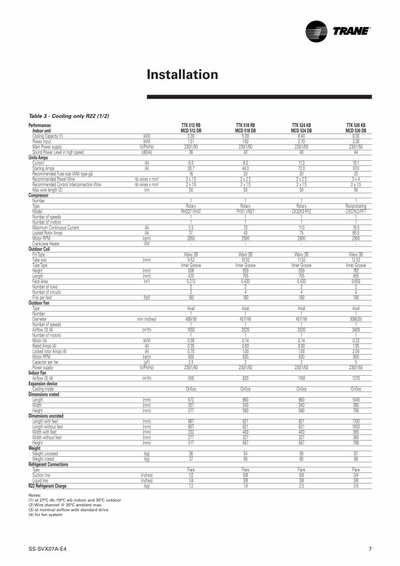
Table 3 - Cooling only R22 (1/2)
Performances TTK 512 RB TTK 518 RB TTK 524 KB TTK 530 KBIndoor unit MCD 512 DB MCD 518 DB MCD 524 DB MCD 530 DBCooling Capacity (1) (kW) 3.30 5.00 6.40 8.30Power Input (kW) 1.51 1.62 2.70 3.30Main Power supply (V/Ph/Hz) 230/1/50 230/1/50 230/1/50 230/1/50Sound Power Level in high speed (dB(A)) 36 43 40 44
Units AmpsCurrent (A) 6.0 8.0 11.3 19.1Starting Amps (A) 28.7 44.0 72.0 97.0Recommended Fuse size (AM) type gG 16 20 20 25Recommended Power Wire nb wires x mm2 3 x 1.5 3 x 2.5 3 x 2.5 3 x 4Recommended Control Interconnection Wire nb wires x mm2 2 x 1.5 2 x 1.5 2 x 1.5 2 x 1.5Max wire length (2) (m) 50 50 50 50
CompressorNumber 1 1 1 1Type Rotary Rotary Rotary ReciprocatingModel RH207 VHAT PH31 VNET CK32K3-PFZ CR37KQ-PFTNumber of speeds 1 1 1 1Number of motors 1 1 1 1Maximum Continuous Current (A) 5.5 7.0 11.0 18.5Locked Rotor Amps (A) 31 43 75 85.5Motor RPM (rpm) 2850 2900 2900 2900Crankcase Heater (W) - - - -
Outdoor CoilFin Type Wavy 3B Wavy 3B Wavy 3B Wavy 3BTube size (mm) 9.52 10.52 11.52 12.52Tube Type Inner Groove Inner Groove Inner Groove Inner GrooveHeight (mm) 508 559 559 762Length (mm) 420 755 755 855Face Area (m2) 0.213 0.420 0.420 0.650Number of rows 2 2 2 2Number of circuits 2 4 4 4Fins per feet (fpf) 180 180 180 180
Outdoor FanType Axial Axial Axial AxialNumber 1 1 1 1Diameter mm (inches) 406(16) 457(18) 457(18) 508(20)Number of speeds 1 1 1 1Airflow (3) (4) (m3/h) 1050 2020 2020 3400Number of motors 1 1 1 1Motor (4) (kW) 0.08 0.14 0.14 0.23Rated Amps (4) (A) 0.35 0.60 0.60 1.05Locked rotor Amps (4) (A) 0.70 1.00 1.00 2.04Motor RPM (rpm) 930 930 930 900Capacitor per fan (µF) 2.5 2 2 5Power supply (V/Ph/Hz) 230/1/50 230/1/50 230/1/50 230/1/50
Indoor FanAirflow (3) (4) (m3/h) 550 820 1100 1370
Expansion deviceCooling mode Orifice Orifice Orifice Orifice
Dimensions cratedLength (mm) 672 860 860 1045Width (mm) 357 340 340 380Height (mm) 577 580 580 790
Dimensions uncratedLength with feet (mm) 667 821 821 1100Length without feet (mm) 667 821 821 1003Width with feet (mm) 332 400 400 365Width without feet (mm) 277 327 327 365Height (mm) 517 567 567 790
WeightWeight uncrated (kg) 36 54 58 87Weight crated (kg) 37 56 60 89
Refrigerant ConnectionsType Flare Flare Flare FlareSuction line (inches) 1/2 5/8 5/8 3/4Liquid line (inches) 1/4 3/8 3/8 3/8
R22 Refrigerant Charge (kg) 1.2 1.9 2.5 3.6
Notes:(1) at 27°C db /19°C wb indoor and 35°C outdoor(2) Wire channel @ 35°C ambient max.(3) at nominal airflow with standard drive(4) for fan system
8 SS-SVX07A-E4
Installation
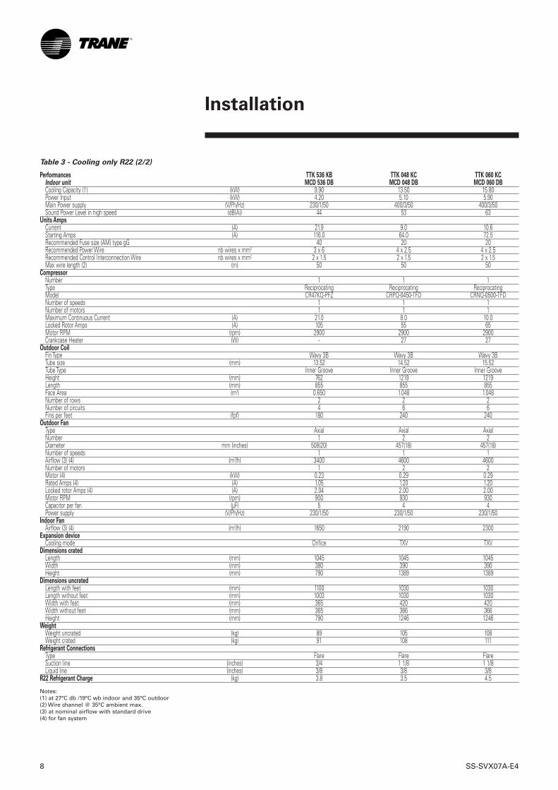
Table 3 - Cooling only R22 (2/2)
Performances TTK 536 KB TTK 048 KC TTK 060 KCIndoor unit MCD 536 DB MCD 048 DB MCD 060 DBCooling Capacity (1) (kW) 9.90 13.50 15.80Power Input (kW) 4.20 5.10 5.90Main Power supply (V/Ph/Hz) 230/1/50 400/3/50 400/3/50Sound Power Level in high speed (dB(A)) 44 53 63
Units AmpsCurrent (A) 21.9 9.0 10.6Starting Amps (A) 116.0 64.0 72.5Recommended Fuse size (AM) type gG 40 20 20Recommended Power Wire nb wires x mm2 3 x 6 4 x 2.5 4 x 2.5Recommended Control Interconnection Wire nb wires x mm2 2 x 1.5 2 x 1.5 2 x 1.5Max wire length (2) (m) 50 50 50
CompressorNumber 1 1 1Type Reciprocating Reciprocating ReciprocatingModel CR47KQ-PFZ CRPQ-0450-TFD CRNQ-0500-TFDNumber of speeds 1 1 1Number of motors 1 1 1Maximum Continuous Current (A) 21.0 8.0 10.0Locked Rotor Amps (A) 105 55 65Motor RPM (rpm) 2900 2900 2900Crankcase Heater (W) - 27 27
Outdoor CoilFin Type Wavy 3B Wavy 3B Wavy 3BTube size (mm) 13.52 14.52 15.52Tube Type Inner Groove Inner Groove Inner GrooveHeight (mm) 762 1219 1219Length (mm) 855 855 855Face Area (m2) 0.650 1.048 1.048Number of rows 2 2 2Number of circuits 4 6 6Fins per feet (fpf) 180 240 240
Outdoor FanType Axial Axial AxialNumber 1 2 2Diameter mm (inches) 508(20) 457(18) 457(18)Number of speeds 1 1 1Airflow (3) (4) (m3/h) 3400 4600 4600Number of motors 1 2 2Motor (4) (kW) 0.23 0.29 0.29Rated Amps (4) (A) 1.05 1.20 1.20Locked rotor Amps (4) (A) 2.04 2.00 2.00Motor RPM (rpm) 900 930 930Capacitor per fan (µF) 5 4 4Power supply (V/Ph/Hz) 230/1/50 230/1/50 230/1/50
Indoor FanAirflow (3) (4) (m3/h) 1650 2190 2300
Expansion deviceCooling mode Orifice TXV TXV
Dimensions cratedLength (mm) 1045 1045 1045Width (mm) 380 390 390Height (mm) 790 1389 1389
Dimensions uncratedLength with feet (mm) 1100 1030 1030Length without feet (mm) 1003 1030 1030Width with feet (mm) 365 420 420Width without feet (mm) 365 366 366Height (mm) 790 1246 1246
WeightWeight uncrated (kg) 89 105 108Weight crated (kg) 91 108 111
Refrigerant ConnectionsType Flare Flare FlareSuction line (inches) 3/4 1 1/8 1 1/8Liquid line (inches) 3/8 3/8 3/8
R22 Refrigerant Charge (kg) 3.8 3.5 4.5
Notes:(1) at 27°C db /19°C wb indoor and 35°C outdoor(2) Wire channel @ 35°C ambient max.(3) at nominal airflow with standard drive(4) for fan system
SS-SVX07A-E4 9
Installation
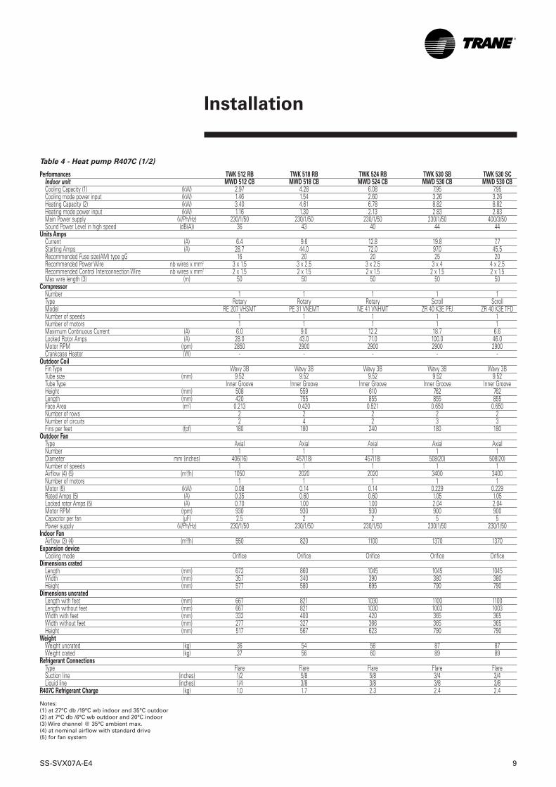
Table 4 - Heat pump R407C (1/2)
Performances TWK 512 RB TWK 518 RB TWK 524 RB TWK 530 SB TWK 530 SCIndoor unit MWD 512 CB MWD 518 CB MWD 524 CB MWD 530 CB MWD 530 CBCooling Capacity (1) (kW) 2.97 4.28 6.08 7.95 7.95Cooling mode power input (kW) 1.46 1.54 2.60 3.26 3.26Heating Capacity (2) (kW) 3.40 4.61 6.78 8.82 8.82Heating mode power input (kW) 1.16 1.30 2.13 2.83 2.83Main Power supply (V/Ph/Hz) 230/1/50 230/1/50 230/1/50 230/1/50 400/3/50Sound Power Level in high speed (dB(A)) 36 43 40 44 44
Units AmpsCurrent (A) 6.4 9.6 12.8 19.8 7.7Starting Amps (A) 28.7 44.0 72.0 97.0 45.5Recommended Fuse size(AM) type gG 16 20 20 25 20Recommended Power Wire nb wires x mm2 3 x 1.5 3 x 2.5 3 x 2.5 3 x 4 4 x 2.5Recommended Control Interconnection Wire nb wires x mm2 2 x 1.5 2 x 1.5 2 x 1.5 2 x 1.5 2 x 1.5Max wire length (3) (m) 50 50 50 50 50
CompressorNumber 1 1 1 1 1Type Rotary Rotary Rotary Scroll ScrollModel RE 207 VHSMT PE 31 VNEMT NE 41 VNHMT ZR 40 K3E PFJ ZR 40 K3E TFDNumber of speeds 1 1 1 1 1Number of motors 1 1 1 1 1Maximum Continuous Current (A) 6.0 9.0 12.2 18.7 6.6Locked Rotor Amps (A) 28.0 43.0 71.0 100.0 46.0Motor RPM (rpm) 2850 2900 2900 2900 2900Crankcase Heater (W) - - - - -
Outdoor CoilFin Type Wavy 3B Wavy 3B Wavy 3B Wavy 3B Wavy 3BTube size (mm) 9.52 9.52 9.52 9.52 9.52Tube Type Inner Groove Inner Groove Inner Groove Inner Groove Inner GrooveHeight (mm) 508 559 610 762 762Length (mm) 420 755 855 855 855Face Area (m2) 0.213 0.420 0.521 0.650 0.650Number of rows 2 2 2 2 2Number of circuits 2 4 2 3 3Fins per feet (fpf) 180 180 240 180 180
Outdoor FanType Axial Axial Axial Axial AxialNumber 1 1 1 1 1Diameter mm (inches) 406(16) 457(18) 457(18) 508(20) 508(20)Number of speeds 1 1 1 1 1Airflow (4) (5) (m3/h) 1050 2020 2020 3400 3400Number of motors 1 1 1 1 1Motor (5) (kW) 0.08 0.14 0.14 0.229 0.229Rated Amps (5) (A) 0.35 0.60 0.60 1.05 1.05Locked rotor Amps (5) (A) 0.70 1.00 1.00 2.04 2.04Motor RPM (rpm) 930 930 930 900 900Capacitor per fan (µF) 2.5 2 2 5 5Power supply (V/Ph/Hz) 230/1/50 230/1/50 230/1/50 230/1/50 230/1/50
Indoor FanAirflow (3) (4) (m3/h) 550 820 1100 1370 1370
Expansion deviceCooling mode Orifice Orifice Orifice Orifice Orifice
Dimensions cratedLength (mm) 672 860 1045 1045 1045Width (mm) 357 340 390 380 380Height (mm) 577 580 695 790 790
Dimensions uncratedLength with feet (mm) 667 821 1030 1100 1100Length without feet (mm) 667 821 1030 1003 1003Width with feet (mm) 332 400 420 365 365Width without feet (mm) 277 327 366 365 365Height (mm) 517 567 623 790 790
WeightWeight uncrated (kg) 36 54 58 87 87Weight crated (kg) 37 56 60 89 89
Refrigerant ConnectionsType Flare Flare Flare Flare FlareSuction line (inches) 1/2 5/8 5/8 3/4 3/4Liquid line (inches) 1/4 3/8 3/8 3/8 3/8
R407C Refrigerant Charge (kg) 1.0 1.7 2.3 2.4 2.4
Notes:(1) at 27°C db /19°C wb indoor and 35°C outdoor(2) at 7°C db /6°C wb outdoor and 20°C indoor(3) Wire channel @ 35°C ambient max.(4) at nominal airflow with standard drive(5) for fan system
10 SS-SVX07A-E4
Installation
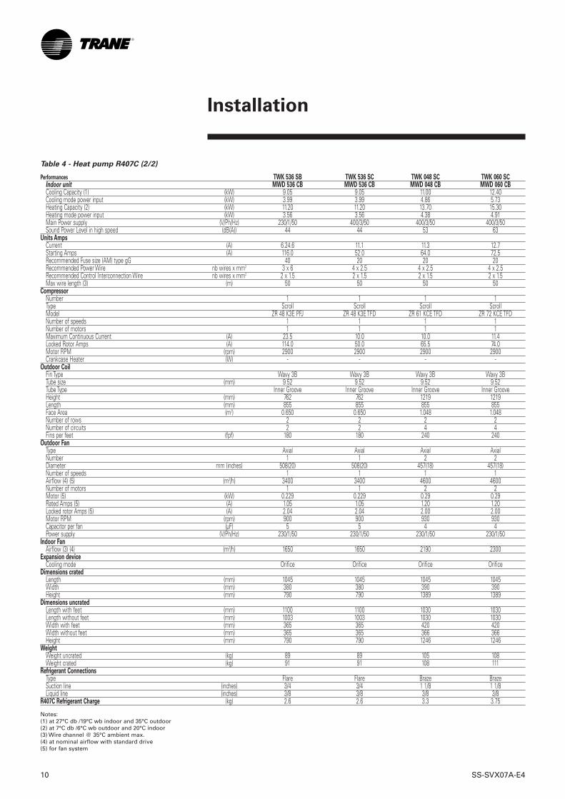
Table 4 - Heat pump R407C (2/2)
Performances TWK 536 SB TWK 536 SC TWK 048 SC TWK 060 SCIndoor unit MWD 536 CB MWD 536 CB MWD 048 CB MWD 060 CBCooling Capacity (1) (kW) 9.05 9.05 11.00 12.40Cooling mode power input (kW) 3.99 3.99 4.86 5.73Heating Capacity (2) (kW) 11.20 11.20 13.70 15.30Heating mode power input (kW) 3.56 3.56 4.38 4.91Main Power supply (V/Ph/Hz) 230/1/50 400/3/50 400/3/50 400/3/50Sound Power Level in high speed (dB(A)) 44 44 53 63
Units AmpsCurrent (A) 6.24.6 11.1 11.3 12.7Starting Amps (A) 116.0 52.0 64.0 72.5Recommended Fuse size (AM) type gG 40 20 20 20Recommended Power Wire nb wires x mm2 3 x 6 4 x 2.5 4 x 2.5 4 x 2.5Recommended Control Interconnection Wire nb wires x mm2 2 x 1.5 2 x 1.5 2 x 1.5 2 x 1.5Max wire length (3) (m) 50 50 50 50
CompressorNumber 1 1 1 1Type Scroll Scroll Scroll ScrollModel ZR 48 K3E PFJ ZR 48 K3E TFD ZR 61 KCE TFD ZR 72 KCE TFDNumber of speeds 1 1 1 1Number of motors 1 1 1 1Maximum Continuous Current (A) 23.5 10.0 10.0 11.4Locked Rotor Amps (A) 114.0 50.0 65.5 74.0Motor RPM (rpm) 2900 2900 2900 2900Crankcase Heater (W) - - - -
Outdoor CoilFin Type Wavy 3B Wavy 3B Wavy 3B Wavy 3BTube size (mm) 9.52 9.52 9.52 9.52Tube Type Inner Groove Inner Groove Inner Groove Inner GrooveHeight (mm) 762 762 1219 1219Length (mm) 855 855 855 855Face Area (m2) 0.650 0.650 1.048 1.048Number of rows 2 2 2 2Number of circuits 2 2 4 4Fins per feet (fpf) 180 180 240 240
Outdoor FanType Axial Axial Axial AxialNumber 1 1 2 2Diameter mm (inches) 508(20) 508(20) 457(18) 457(18)Number of speeds 1 1 1 1Airflow (4) (5) (m3/h) 3400 3400 4600 4600Number of motors 1 1 2 2Motor (5) (kW) 0.229 0.229 0.29 0.29Rated Amps (5) (A) 1.05 1.05 1.20 1.20Locked rotor Amps (5) (A) 2.04 2.04 2.00 2.00Motor RPM (rpm) 900 900 930 930Capacitor per fan (µF) 5 5 4 4Power supply (V/Ph/Hz) 230/1/50 230/1/50 230/1/50 230/1/50
Indoor FanAirflow (3) (4) (m3/h) 1650 1650 2190 2300
Expansion deviceCooling mode Orifice Orifice Orifice Orifice
Dimensions cratedLength (mm) 1045 1045 1045 1045Width (mm) 380 380 390 390Height (mm) 790 790 1389 1389
Dimensions uncratedLength with feet (mm) 1100 1100 1030 1030Length without feet (mm) 1003 1003 1030 1030Width with feet (mm) 365 365 420 420Width without feet (mm) 365 365 366 366Height (mm) 790 790 1246 1246
WeightWeight uncrated (kg) 89 89 105 108Weight crated (kg) 91 91 108 111
Refrigerant ConnectionsType Flare Flare Braze BrazeSuction line (inches) 3/4 3/4 1 1/8 1 1/8Liquid line (inches) 3/8 3/8 3/8 3/8
R407C Refrigerant Charge (kg) 2.6 2.6 3.3 3.75
Notes:(1) at 27°C db /19°C wb indoor and 35°C outdoor(2) at 7°C db /6°C wb outdoor and 20°C indoor(3) Wire channel @ 35°C ambient max.(4) at nominal airflow with standard drive(5) for fan system
SS-SVX07A-E4 11
Installation
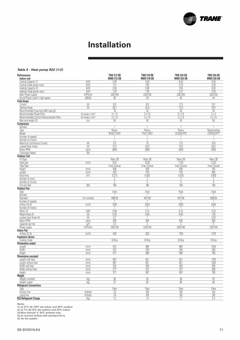
Table 5 - Heat pump R22 (1/2)
Performances TWK 512 RB TWK 518 RB TWK 524 KB TWK 530 KBIndoor unit MWD 512 DB MWD 518 DB MWD 524 DB MWD 530 DBCooling Capacity (1) (kW) 3.30 5.00 6.40 8.30Cooling mode power input (kW) 1.51 1.62 2.70 3.30Heating Capacity (2) (kW) 3.50 5.90 7.50 9.30Heating mode power input (kW) 1.20 1.35 2.21 2.92Main Power supply (V/Ph/Hz) 230/1/50 230/1/50 230/1/50 230/1/50Sound Power Level in high speed (dB(A)) 36 43 40 44
Units AmpsCurrent (A) 6.0 8.0 11.3 19.1Starting Amps (A) 28.7 44.0 72.0 97.0Recommended Fuse size (AM) type gG 16 20 20 25Recommended Power Wire nb wires x mm2 3 x 1.5 3 x 2.5 3 x 2.5 3 x 4Recommended Control Interconnection Wire nb wires x mm2 2 x 1.5 2 x 1.5 2 x 1.5 2 x 1.5Max wire length (2) (m) 50 50 50 50
CompressorNumber 1 1 1 1Type Rotary Rotary Rotary ReciprocatingModel RH207 VHAT PH31 VNET CK32K3-PFZ CR37KQ-PFTNumber of speeds 1 1 1 1Number of motors 1 1 1 1Maximum Continuous Current (A) 5.5 7.0 11.0 18.5Locked Rotor Amps (A) 31.0 43.0 75.0 85.5Motor RPM (rpm) 2850 2900 2900 2900Crankcase Heater (W) - - - -
Outdoor CoilFin Type Wavy 3B Wavy 3B Wavy 3B Wavy 3BTube size (mm) 9.52 10.52 11.52 12.52Tube Type Inner Groove Inner Groove Inner Groove Inner GrooveHeight (mm) 508 559 559 762Length (mm) 420 755 755 855Face Area (m2) 0.213 0.420 0.420 0.650Number of rows 2 2 2 2Number of circuits 2 4 4 4Fins per feet (fpf) 180 180 180 180
Outdoor FanType Axial Axial Axial AxialNumber 1 1 1 1Diameter mm (inches) 406(16) 457(18) 457(18) 508(20)Number of speeds 1 1 1 1Airflow (3) (4) (m3/h) 1050 2020 2020 3400Number of motors 1 1 1 1Motor (4) (kW) 0.08 0.14 0.14 0.23Rated Amps (4) (A) 0.35 0.60 0.60 1.05Locked rotor Amps (4) (A) 0.7 1 1 2.04Motor RPM (rpm) 930 930 930 900Capacitor per fan (µF) 2.5 2 2 5Power supply (V/Ph/Hz) 230/1/50 230/1/50 230/1/50 230/1/50
Indoor FanAirflow (3) (4) (m3/h) 550 820 1100 1370
Expansion deviceCooling mode Orifice Orifice Orifice Orifice
Dimensions cratedLength (mm) 672 860 860 1045Width (mm) 357 340 340 380Height (mm) 577 580 580 790
Dimensions uncratedLength with feet (mm) 667 821 821 1100Length without feet (mm) 667 821 821 1003Width with feet (mm) 332 400 400 365Width without feet (mm) 277 327 327 365Height (mm) 517 567 567 790
WeightWeight uncrated (kg) 36 54 58 87Weight crated (kg) 37 56 60 89
Refrigerant ConnectionsType Flare Flare Flare FlareSuction line (inches) 1/2 5/8 5/8 3/4Liquid line (inches) 1/4 3/8 3/8 3/8
R22 Refrigerant Charge (kg) 1.2 1.4 1.7 2.4
Notes:(1) at 27°C db /19°C wb indoor and 35°C outdoor(2) at 7°C db /6°C wb outdoor and 20°C indoor(3) Wire channel @ 35°C ambient max.(4) at nominal airflow with standard drive(5) for fan system

Installation
12 SS-SVX07A-E4
Table 5 - Heat pump R22 (2/2)
Performances TWK 536 KB TWK 048 KC TWK 060 KCIndoor unit MWD 536 DB MWD 048 DB MWD 060 DBCooling Capacity (1) (kW) 9.90 13.50 15.80Cooling mode power input (kW) 4.2 5.10 5.90Heating Capacity (2) (kW) 11.10 15.10 17.70Heating mode power input (kW) 3.66 4.45 5.20Main Power supply (V/Ph/Hz) 230/1/50 400/3/50 400/3/50Sound Power Level in high speed (dB(A)) 44 53 63
Units AmpsCurrent (A) 21.9 9.0 10.6Starting Amps (A) 116.0 64.0 72.5Recommended Fuse size (AM) type gG 40 20 20Recommended Power Wire nb wires x mm2 3 x 6 4 x 2.5 4 x 2.5Recommended Control Interconnection Wire nb wires x mm2 2 x 1.5 2 x 1.5 2 x 1.5Max wire length (2) (m) 50 50 50
CompressorNumber 1 1 1Type Reciprocating Reciprocating ReciprocatingModel CR47KQ-PFZ CRPQ-0450-TFD CRNQ-0500-TFDNumber of speeds 1 1 1Number of motors 1 1 1Maximum Continuous Current (A) 21.0 8.0 10.0Locked Rotor Amps (A) 105.0 55.0 65.0Motor RPM (rpm) 2900 2900 2900Crankcase Heater (W) - 27 27
Outdoor CoilFin Type Wavy 3B Wavy 3B Wavy 3BTube size (mm) 13.52 14.52 15.52Tube Type Inner Groove Inner Groove Inner GrooveHeight (mm) 762 1219 1219Length (mm) 855 855 855Face Area (m2) 0.650 1.048 1.048Number of rows 2 2 2Number of circuits 4 6 6Fins per feet (fpf) 180 240 240
Outdoor FanType Axial Axial AxialNumber 1 2 2Diameter mm (inches) 508(20) 457(18) 457(18)Number of speeds 1 1 1Airflow (3) (4) (m3/h) 3400 4600 4600Number of motors 1 2 2Motor (4) (kW) 0.23 0.29 0.29Rated Amps (4) (A) 1.05 1.20 1.20Locked rotor Amps (4) (A) 2.04 2 2Motor RPM (rpm) 900 930 930Capacitor per fan (µF) 5 4 4Power supply (V/Ph/Hz) 230/1/50 230/1/50 230/1/50
Indoor FanAirflow (3) (4) (m3/h) 1650 2190 2300
Expansion deviceCooling mode Orifice TXV TXV
Dimensions cratedLength (mm) 1045 1045 1045Width (mm) 380 390 390Height (mm) 790 1389 1389
Dimensions uncratedLength with feet (mm) 1100 1030 1030Length without feet (mm) 1003 1030 1030Width with feet (mm) 365 420 420Width without feet (mm) 365 366 366Height (mm) 790 1246 1246
WeightWeight uncrated (kg) 89 105 108Weight crated (kg) 91 108 111
Refrigerant ConnectionsType Flare Flare FlareSuction line (inches) 3/4 1 1/8 1 1/8Liquid line (inches) 3/8 3/8 3/8
R22 Refrigerant Charge (kg) 2.6 3.5 4.5
Notes:(1) at 27°C db /19°C wb indoor and 35°C outdoor(2) at 7°C db /6°C wb outdoor and 20°C indoor(3) Wire channel @ 35°C ambient max.(4) at nominal airflow with standard drive(5) for fan system
SS-SVX07A-E4 13
Installation
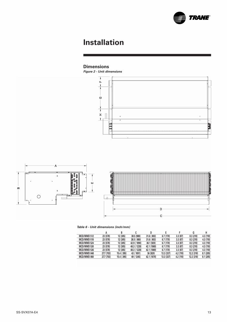
Table 6 - Unit dimensions (inch/mm)
A B C D E F G HMCD/MWD 512 23 (578) 12 (305) 38.5 (980) 31.6 ( 803) 6.7 (170) 3.3 (87) 8.3 (210) 4.3 (110)MCD/MWD 518 23 (578) 12 (305) 38.5 ( 980) 31.6 ( 803) 6.7 (170) 3.3 (87) 8.3 (210) 4.3 (110)MCD/MWD 524 23 (578) 12 (305) 42.9 ( 1090) 36.1 (920) 6.7 (170) 3.3 (87) 8.3 (210) 4.3 (110)MCD/MWD 530 23 (578) 12 (305) 48.3 ( 1228) 42.1 (1069) 6.7 (170) 3.3 (87) 8.3 (210) 4.3 (110)MCD/MWD 536 23 (578) 12 (305) 48.3 ( 1228) 42.1 (1069) 6.7 (170) 3.3 (87) 8.3 (210) 4.3 (110)MCD/MWD 048 27.7 (703) 15.4 ( 395) 43 ( 1091) 36 (920) 13.3 (337) 4.2 (110) 12.2 (310) 8.1 (205)MCD/MWD 060 27.7 (703) 15.4 ( 395) 49 ( 1245) 42.1 (1070) 13.3 (337) 4.2 (110) 12.2 (310) 8.1 (205)
Dimensions Figure 2 - Unit dimensions
14 SS-SVX07A-E4
Installation
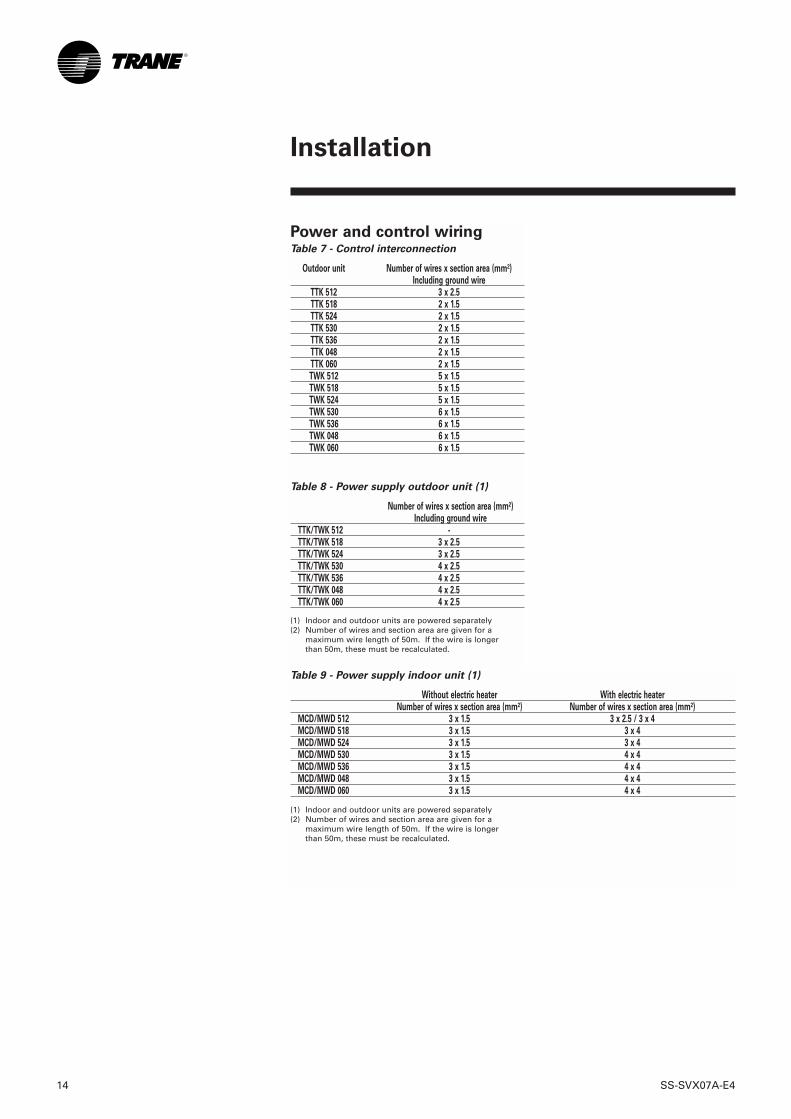
Power and control wiringTable 7 - Control interconnection
Outdoor unit Number of wires x section area (mm²)Including ground wire
TTK 512 3 x 2.5TTK 518 2 x 1.5TTK 524 2 x 1.5TTK 530 2 x 1.5TTK 536 2 x 1.5TTK 048 2 x 1.5TTK 060 2 x 1.5TWK 512 5 x 1.5TWK 518 5 x 1.5TWK 524 5 x 1.5TWK 530 6 x 1.5TWK 536 6 x 1.5TWK 048 6 x 1.5TWK 060 6 x 1.5
Table 8 - Power supply outdoor unit (1)
Number of wires x section area (mm²)Including ground wire
TTK/TWK 512 -TTK/TWK 518 3 x 2.5TTK/TWK 524 3 x 2.5TTK/TWK 530 4 x 2.5TTK/TWK 536 4 x 2.5TTK/TWK 048 4 x 2.5TTK/TWK 060 4 x 2.5
(1) Indoor and outdoor units are powered separately(2) Number of wires and section area are given for a
maximum wire length of 50m. If the wire is longerthan 50m, these must be recalculated.
Table 9 - Power supply indoor unit (1)
Without electric heater With electric heaterNumber of wires x section area (mm²) Number of wires x section area (mm²)
MCD/MWD 512 3 x 1.5 3 x 2.5 / 3 x 4MCD/MWD 518 3 x 1.5 3 x 4MCD/MWD 524 3 x 1.5 3 x 4MCD/MWD 530 3 x 1.5 4 x 4MCD/MWD 536 3 x 1.5 4 x 4MCD/MWD 048 3 x 1.5 4 x 4MCD/MWD 060 3 x 1.5 4 x 4
(1) Indoor and outdoor units are powered separately(2) Number of wires and section area are given for a
maximum wire length of 50m. If the wire is longerthan 50m, these must be recalculated.
SS-SVX07A-E4 15
Installation
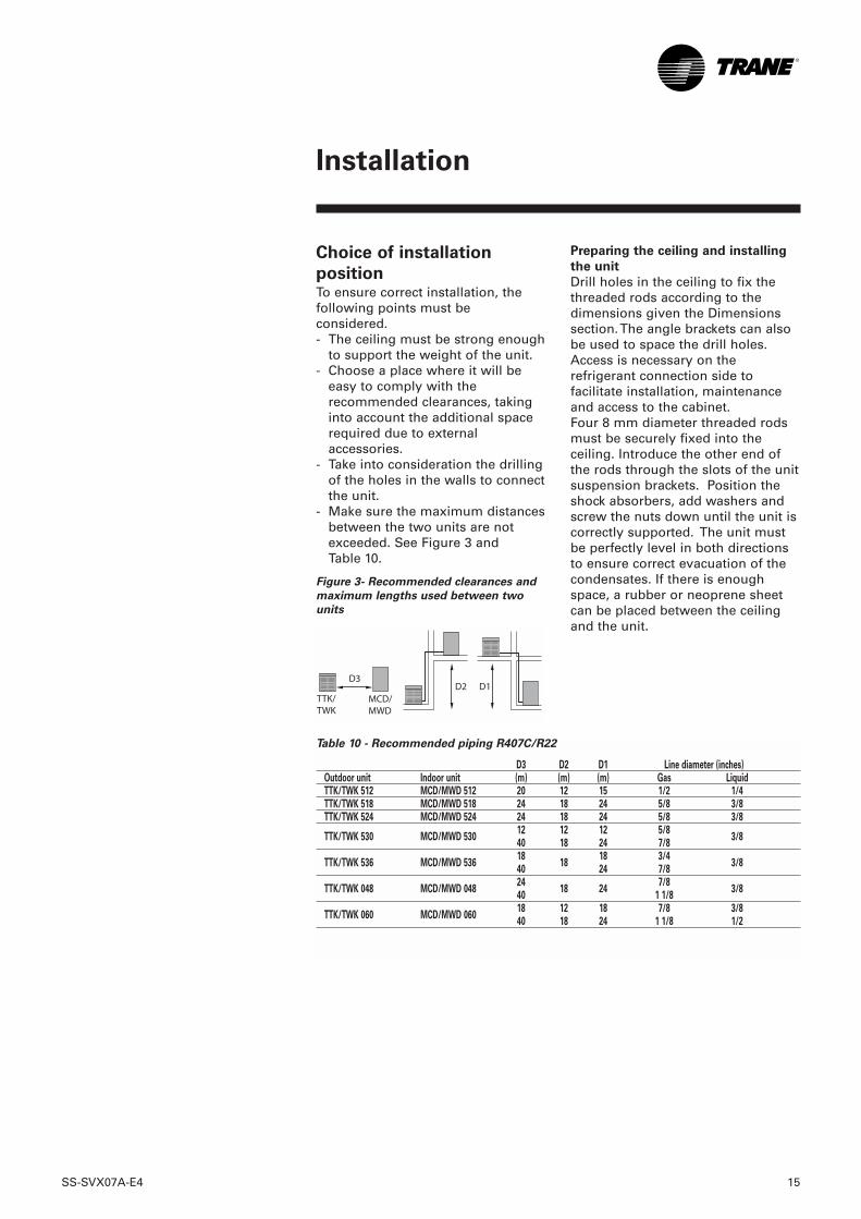
Table 10 - Recommended piping R407C/R22
D3 D2 D1 Line diameter (inches)Outdoor unit Indoor unit (m) (m) (m) Gas LiquidTTK/TWK 512 MCD/MWD 512 20 12 15 1/2 1/4TTK/TWK 518 MCD/MWD 518 24 18 24 5/8 3/8TTK/TWK 524 MCD/MWD 524 24 18 24 5/8 3/8
TTK/TWK 530 MCD/MWD 53012 12 12 5/8
3/840 18 24 7/8
TTK/TWK 536 MCD/MWD 53618
1818 3/4
3/840 24 7/8
TTK/TWK 048 MCD/MWD 04824
18 247/8
3/840 1 1/8
TTK/TWK 060 MCD/MWD 06018 12 18 7/8 3/840 18 24 1 1/8 1/2
Choice of installation
positionTo ensure correct installation, thefollowing points must beconsidered.- The ceiling must be strong enough
to support the weight of the unit.- Choose a place where it will be
easy to comply with therecommended clearances, takinginto account the additional spacerequired due to externalaccessories.
- Take into consideration the drillingof the holes in the walls to connectthe unit.
- Make sure the maximum distancesbetween the two units are notexceeded. See Figure 3 andTable 10.
Figure 3- Recommended clearances and
maximum lengths used between two
units
Preparing the ceiling and installing
the unit
Drill holes in the ceiling to fix thethreaded rods according to thedimensions given the Dimensionssection. The angle brackets can alsobe used to space the drill holes.Access is necessary on therefrigerant connection side tofacilitate installation, maintenanceand access to the cabinet. Four 8 mm diameter threaded rodsmust be securely fixed into theceiling. Introduce the other end ofthe rods through the slots of the unitsuspension brackets. Position theshock absorbers, add washers andscrew the nuts down until the unit iscorrectly supported. The unit mustbe perfectly level in both directionsto ensure correct evacuation of thecondensates. If there is enoughspace, a rubber or neoprene sheetcan be placed between the ceilingand the unit.

16 SS-SVX07A-E4
Installation
Refrigerant connections
It is possible to remove the electricalcabinet to facilitate access to therefrigerant connection.
Installation procedure
- Make sure the route taken by yourrefrigerant lines is as short aspossible.
- Limit pressure losses in the lineswhich may be caused by crushingof the lines, a large number ofbends or bending radii that are toosmall.
- Slope all the gas lines leaving theindoor unit so that oil can return tothe compressor by gravity.
· Prevent any possibility of oiltrapped in the gas lines.
CAUTION!
An insufficiently lubricatedcompressor may break down.
If the vertical difference in levelbetween the units is greater than2.5 m, an oil trap must be positionedat the bottom of the vertical line, andan additional trap must bepositioned every 7.5 m of verticalelevation to allow oil return to thecompressor. There are no specialtechnical recommendations forliquid lines because of the well-balanced mixture of refrigerant andoil. Movement of the liquidrefrigerant also causes the oil tomove.
Passage of the tube and cable
bundle
Before drilling into the wall- make sure there are no pipes or
electrical cables in the wall at theplace where you are going to drillprovide a protective sleeve for thebundle of tubes and cables at thepoint where it passes through thehole (Figure 4). If permitted bylegislation, the condensatedrainage line can also be includedin the bundle. Wrap tape aroundall the lines and cables from thebottom of the outside unit to thepoint where the piping enters thewall. Carry out the same operationfor each circuit.
Figure 4 - Protective sleeve
A = Cable bundle1 = Wall2 = Inside3 = Outside
A
SS-SVX07A-E4 17
Installation
Brazed connections
These lines will be created on theinstallation site. They will beinstalled according to normal tradepractice by qualified personnel, incompliance with local legislation.1. Remove the plugs from the units'
refrigerant connections just beforeconnecting the piping, when allthe connections on the refrigerantlines have been terminated. Thiswill prevent contamination byhumidity. Remove the rubberplugs from the ends of the tubes.
2.Use a clean dry copper tube forrefrigeration installations.
3.Use silver brazing alloy only. Donot overheat the welds and carryout nitrogen scavenging inside thetubes to prevent oxidization duringbrazing.
4.Once all the other connectionshave been made, debraze or cutthe plug on the outdoor unit'srefrigerant line connections.Proceed in the same way as forbrazing of the indoor unit's lines.
Line insulation
To prevent heat losses andcondensation, both liquid and gaslines must be thoroughly insulated.
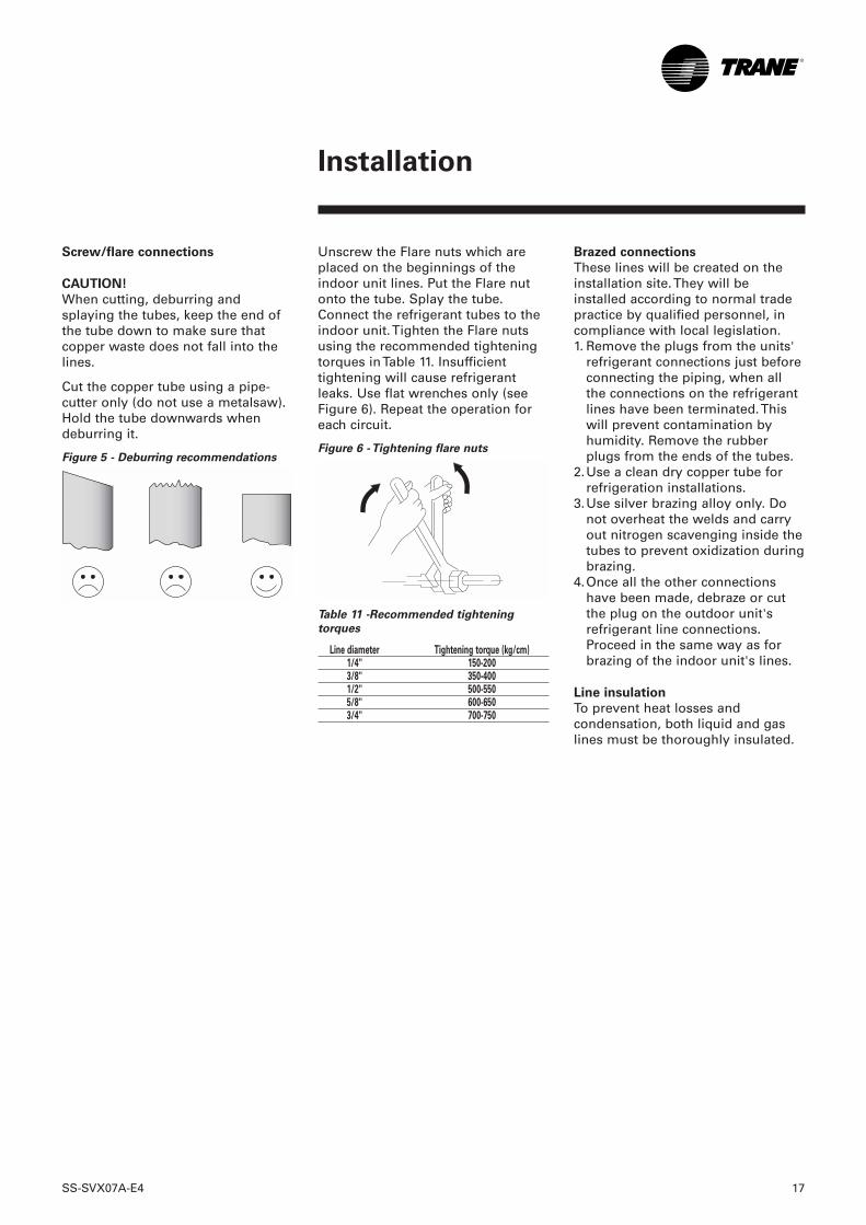
Unscrew the Flare nuts which areplaced on the beginnings of theindoor unit lines. Put the Flare nutonto the tube. Splay the tube.Connect the refrigerant tubes to theindoor unit. Tighten the Flare nutsusing the recommended tighteningtorques in Table 11. Insufficienttightening will cause refrigerantleaks. Use flat wrenches only (seeFigure 6). Repeat the operation foreach circuit.
Figure 6 - Tightening flare nuts
Table 11 -Recommended tightening
torques
Line diameter Tightening torque (kg/cm)1/4'' 150-2003/8'' 350-4001/2'' 500-5505/8'' 600-6503/4'' 700-750
Screw/flare connections
CAUTION!
When cutting, deburring andsplaying the tubes, keep the end ofthe tube down to make sure thatcopper waste does not fall into thelines.
Cut the copper tube using a pipe-cutter only (do not use a metalsaw).Hold the tube downwards whendeburring it.
Figure 5 - Deburring recommendations
18 SS-SVX07A-E4
Installation
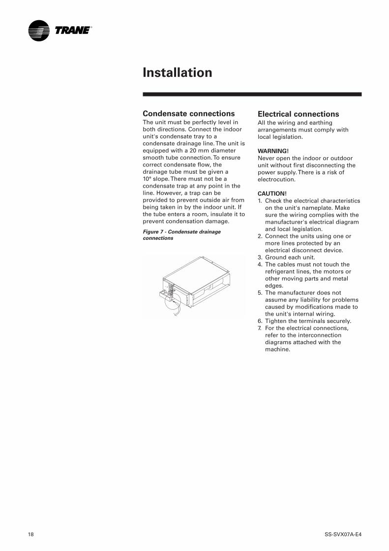
Condensate connectionsThe unit must be perfectly level inboth directions. Connect the indoorunit's condensate tray to acondensate drainage line. The unit isequipped with a 20 mm diametersmooth tube connection. To ensurecorrect condensate flow, thedrainage tube must be given a10° slope. There must not be acondensate trap at any point in theline. However, a trap can beprovided to prevent outside air frombeing taken in by the indoor unit. Ifthe tube enters a room, insulate it toprevent condensation damage.
Figure 7 - Condensate drainage
connections
Electrical connectionsAll the wiring and earthingarrangements must comply withlocal legislation.
WARNING!
Never open the indoor or outdoorunit without first disconnecting thepower supply. There is a risk ofelectrocution.
CAUTION!
1. Check the electrical characteristicson the unit's nameplate. Makesure the wiring complies with themanufacturer's electrical diagramand local legislation.
2. Connect the units using one ormore lines protected by anelectrical disconnect device.
3. Ground each unit.4. The cables must not touch the
refrigerant lines, the motors orother moving parts and metaledges.
5. The manufacturer does notassume any liability for problemscaused by modifications made tothe unit's internal wiring.
6. Tighten the terminals securely.7. For the electrical connections,
refer to the interconnectiondiagrams attached with themachine.
SS-SVX07A-E4 19
Installation
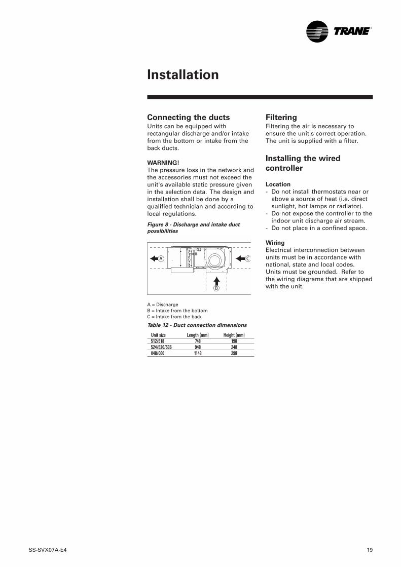
Connecting the ductsUnits can be equipped withrectangular discharge and/or intakefrom the bottom or intake from theback ducts.
WARNING!
The pressure loss in the network andthe accessories must not exceed theunit's available static pressure givenin the selection data. The design andinstallation shall be done by aqualified technician and according tolocal regulations.
Figure 8 - Discharge and intake duct
possibilities
A = DischargeB = Intake from the bottomC = Intake from the back
Table 12 - Duct connection dimensions
Unit size Length (mm) Height (mm)512/518 748 198524/530/536 948 248048/060 1148 298
FilteringFiltering the air is necessary toensure the unit's correct operation.The unit is supplied with a filter.
Installing the wired
controller
Location
- Do not install thermostats near orabove a source of heat (i.e. directsunlight, hot lamps or radiator).
- Do not expose the controller to theindoor unit discharge air stream.
- Do not place in a confined space.
Wiring
Electrical interconnection betweenunits must be in accordance withnational, state and local codes.Units must be grounded. Refer tothe wiring diagrams that are shippedwith the unit.
20 SS-SVX07A-E4
Operation
Creating a vacuumFor this operation, use a pumpcapable of creating a vacuum of1 mm Hg (1.3mbar) or less. To createthe vacuum you must connect thepump to the Schrader pressureconnection on service valveA located on the outdoor unit (gasline). To use the vacuum pump,follow the pump manufacturer'sinstructions. Create a vacuum up to2 mm Hg (2.6mbar) or less. Once thevalue of 2mm Hg or less has beenreached, an increase in pressure willbe observed after a certain time. Themaximum permissible increase is1 mm Hg after 15 minutes. If theincrease is greater and remains at aconstant value, this means there istoo much humidity in the system.In this case, break the vacuum usingdry nitrogen and start the vacuumcreation procedure again.A continuous increase in pressuremeans there is a leak in the system.
WARNING!
Valves A and B must not be openedbefore the installation of therefrigerant circuit has beencompletely finished, or therefrigerant charge will be lost.
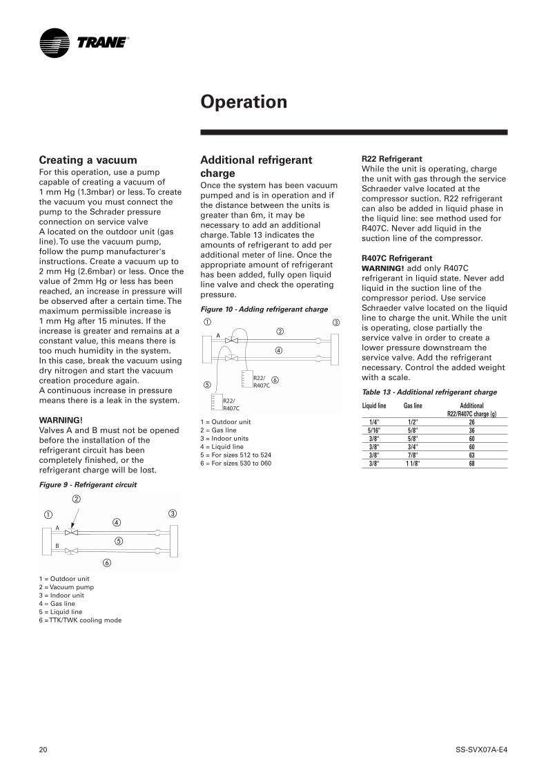
Figure 9 - Refrigerant circuit
1 = Outdoor unit2 = Vacuum pump3 = Indoor unit4 = Gas line5 = Liquid line6 = TTK/TWK cooling mode
Additional refrigerant
charge Once the system has been vacuumpumped and is in operation and ifthe distance between the units isgreater than 6m, it may benecessary to add an additionalcharge. Table 13 indicates theamounts of refrigerant to add peradditional meter of line. Once theappropriate amount of refrigeranthas been added, fully open liquidline valve and check the operatingpressure.
Figure 10 - Adding refrigerant charge
1 = Outdoor unit2 = Gas line3 = Indoor units4 = Liquid line5 = For sizes 512 to 524 6 = For sizes 530 to 060
A
R22 Refrigerant
While the unit is operating, chargethe unit with gas through the serviceSchraeder valve located at thecompressor suction. R22 refrigerantcan also be added in liquid phase inthe liquid line: see method used forR407C. Never add liquid in thesuction line of the compressor.
R407C Refrigerant
WARNING! add only R407Crefrigerant in liquid state. Never addliquid in the suction line of thecompressor period. Use serviceSchraeder valve located on the liquidline to charge the unit. While the unitis operating, close partially theservice valve in order to create alower pressure downstream theservice valve. Add the refrigerantnecessary. Control the added weightwith a scale.
Table 13 - Additional refrigerant charge
Liquid line Gas line Additional R22/R407C charge (g)
1/4'' 1/2'' 26 5/16" 5/8" 36 3/8'' 5/8'' 60 3/8'' 3/4'' 60 3/8'' 7/8'' 63 3/8'' 1 1/8'' 68
SS-SVX07A-E4 21
Operation
Fan speedRefer to the selection data to selectthe static pressure according to theflow rate. From this it is possible todeduce a fan rotation speed. Onceyou have chosen the speed, refer tothe interconnection diagram toconnect the room thermostat to theunit electric cabinet in order topower the correct selected speed.
Configuration and
operationThe unit is equipped with a controlboard that manages operation of thesplit system. It is fitted with 4switches, SW1-1 to SW1-4.
Before start-up by a
qualified technicianOnce the system has been installed,it is recommend to carry out thefollowing checks. 1. Make sure no tools or debris
have been left inside, around oron top of the unit.
2. Unit is perfectly level in bothdirections.
3. Check the electrical connectionshave been correctly done. Checkthe electric power supplycorresponds to the units'nameplates.
4. Make sure the disconnectswitches have been disengaged.
5. Check the refrigerant lines arefixed securely.
6. Check if the condensate drainpan is correctly installed.
7. Check the piping connectionsand the water-tightness of theconnectors using an appropriateleak detection method. Checkthe connections on the site havebeen tightened.
8. Make sure the gas piping andthe condensate drainage tubeare insulated properly to preventproblems with trickling ofcondensation water.
9. Check the fan turns freely. 10. Make sure the intake and
discharge ducts are not blocked.11. Check the filters are correctly
positioned. Show the user howto change the filters.
12. Power up the system andobserve operation carefully:make any necessaryadjustments.
13. Explain to the user how tooperate the unit.
Unit display and
emergency switch
operationFour lamps on the unit display showoperating status. In case of loss ofthe remote control unit, the systemcan be operated temporarily by theemergency switch. The emergencyswitch changes the system mode ofoperation by cycling through thefollowing modes:➠ FAN ➠ COOL ➠ HEAT ➠ AUTO ➠OFF ➠.COOL, HEAT and AUTO operationare at fixed setting of 24°C. Fanspeed is controlled by the AUTOmode. FAN only operation is atHIGH fan speed.
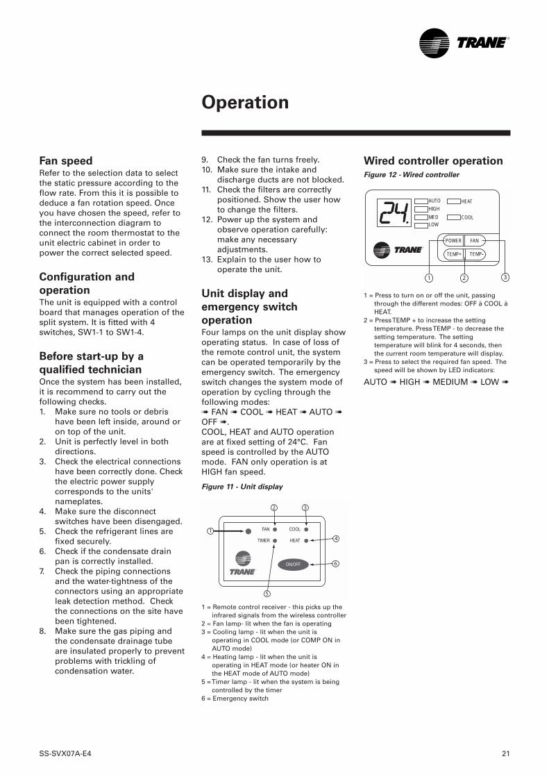
Figure 11 - Unit display
1 = Remote control receiver - this picks up theinfrared signals from the wireless controller
2 = Fan lamp- lit when the fan is operating3 = Cooling lamp - lit when the unit is
operating in COOL mode (or COMP ON inAUTO mode)
4 = Heating lamp - lit when the unit isoperating in HEAT mode (or heater ON inthe HEAT mode of AUTO mode)
5 = Timer lamp - lit when the system is beingcontrolled by the timer
6 = Emergency switch
Wired controller operation
Figure 12 - Wired controller
1 = Press to turn on or off the unit, passingthrough the different modes: OFF à COOL àHEAT.
2 = Press TEMP + to increase the settingtemperature. Press TEMP - to decrease thesetting temperature. The settingtemperature will blink for 4 seconds, thenthe current room temperature will display.
3 = Press to select the required fan speed. Thespeed will be shown by LED indicators:
AUTO ➠ HIGH ➠ MEDIUM ➠ LOW ➠
AUTOHIGHMEDLOW
HEAT
COOL
POWER FAN
TEMP+ TEMP-
22 SS-SVX07A-E4
Operation
Auto (optional)
The unit can be put into 5 differentmodes (FAN, COOL, DRY, HEAT andAUTO). The cycling will be:➠ FAN ➠ COOL ➠ DRY ➠ HEAT ➠HEAT ➠ AUTO ➠When the system is in AUTO mode,the display on the remote controllerwill show COOL and HEAT modes atthe same time.
Louver (optional)
To change the angle of the louver: ifthe button is pressed and released,the angle of the louver is changedone step at a time. If the button ispressed and held, the angle of thelouver is changed until the button isreleased.
Sleep mode
For COOL mode, the settingtemperature will be automaticallyraised 1°C after 1 hour. For HEATmode, the setting temperature willbe automatically lowered 1°C after 1hour.When the system is in SLEEP mode,pressing the SLEEP button willcancel the SLEEP function. Whenthe system is in SLEEP mode,pressing the TEMP button will raisethe setting temperature 1°C from thelast setting.When the system is in SLEEP modeand the unit is stopped by a powerfailure or is turned off, the SLEEPfunction will be canceled.
Wireless controller
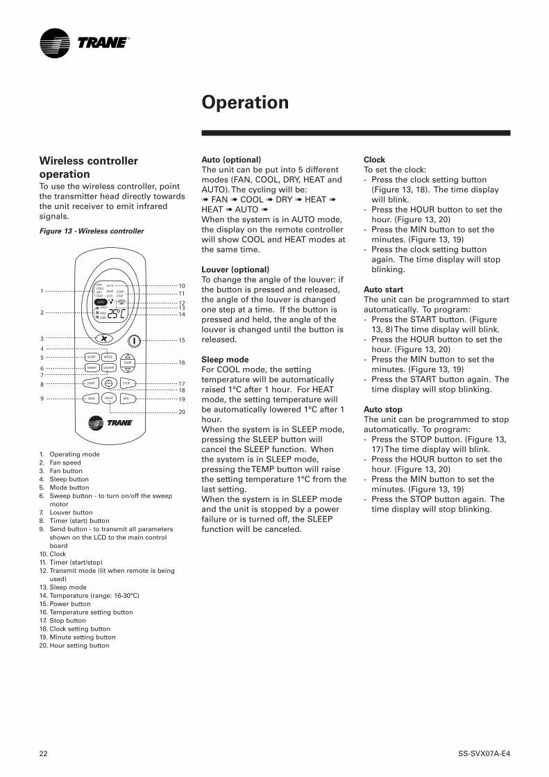
operationTo use the wireless controller, pointthe transmitter head directly towardsthe unit receiver to emit infraredsignals.
Figure 13 - Wireless controller
1. Operating mode2. Fan speed3. Fan button4. Sleep button5. Mode button6. Sweep button - to turn on/off the sweep
motor7. Louver button 8. Timer (start) button9. Send button - to transmit all parameters
shown on the LCD to the main controlboard
10. Clock11. Timer (start/stop)12. Transmit mode (lit when remote is being
used)13. Sleep mode14. Temperature (range: 16-30°C)15. Power button16. Temperature setting button17. Stop button18. Clock setting button19. Minute setting button20. Hour setting button
SLEEP MODE
SWEEP LOUVER
HOUR
START
SEND
TEMP
STOP
MIN
FANCOOLDRYHEAT
10:14
18:40
6:30STARTSTOP
HIGH
MED
LOW
AUTO
Clock
To set the clock:- Press the clock setting button
(Figure 13, 18). The time displaywill blink.
- Press the HOUR button to set thehour. (Figure 13, 20)
- Press the MIN button to set theminutes. (Figure 13, 19)
- Press the clock setting buttonagain. The time display will stopblinking.
Auto start
The unit can be programmed to startautomatically. To program:- Press the START button. (Figure
13, 8) The time display will blink.- Press the HOUR button to set the
hour. (Figure 13, 20)- Press the MIN button to set the
minutes. (Figure 13, 19)- Press the START button again. The
time display will stop blinking.
Auto stop
The unit can be programmed to stopautomatically. To program:- Press the STOP button. (Figure 13,
17) The time display will blink.- Press the HOUR button to set the
hour. (Figure 13, 20)- Press the MIN button to set the
minutes. (Figure 13, 19)- Press the STOP button again. The
time display will stop blinking.
SS-SVX07A-E4 23
Maintenance
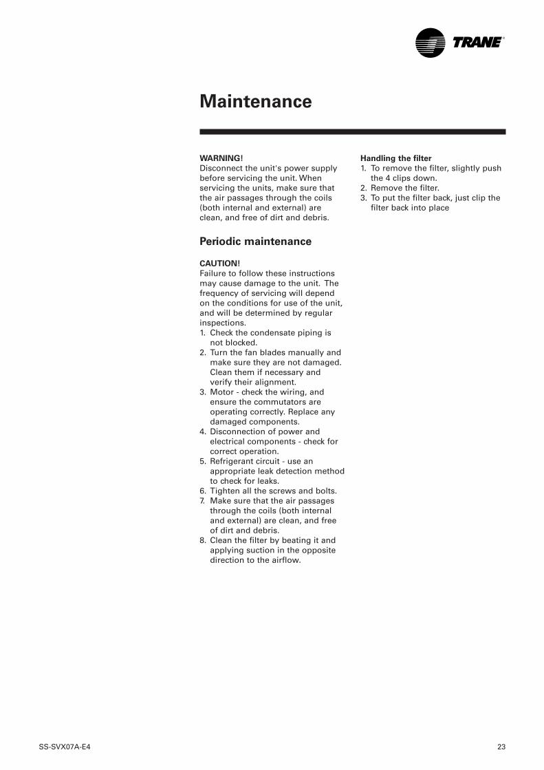
WARNING!
Disconnect the unit's power supplybefore servicing the unit. Whenservicing the units, make sure thatthe air passages through the coils(both internal and external) areclean, and free of dirt and debris.
Periodic maintenance
CAUTION!
Failure to follow these instructionsmay cause damage to the unit. Thefrequency of servicing will dependon the conditions for use of the unit,and will be determined by regularinspections. 1. Check the condensate piping is
not blocked. 2. Turn the fan blades manually and
make sure they are not damaged.Clean them if necessary andverify their alignment.
3. Motor - check the wiring, andensure the commutators areoperating correctly. Replace anydamaged components.
4. Disconnection of power andelectrical components - check forcorrect operation.
5. Refrigerant circuit - use anappropriate leak detection methodto check for leaks.
6. Tighten all the screws and bolts. 7. Make sure that the air passages
through the coils (both internaland external) are clean, and freeof dirt and debris.
8. Clean the filter by beating it andapplying suction in the oppositedirection to the airflow.
Handling the filter
1. To remove the filter, slightly pushthe 4 clips down.
2. Remove the filter.3. To put the filter back, just clip the
filter back into place
24 SS-SVX07A-E4
Maintenance
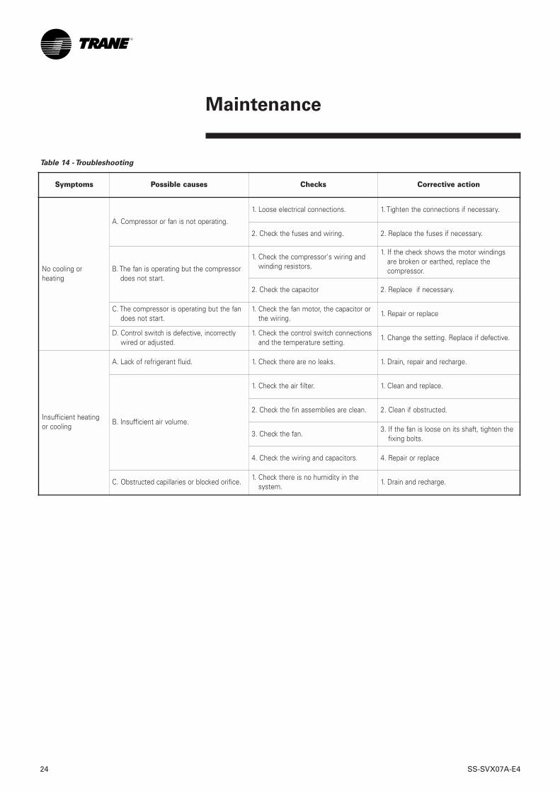
Table 14 - Troubleshooting
Symptoms Possible causes Checks Corrective action
No cooling orheating
A. Compressor or fan is not operating.
1. Loose electrical connections. 1. Tighten the connections if necessary.
2. Check the fuses and wiring. 2. Replace the fuses if necessary.
B. The fan is operating but the compressordoes not start.
1. Check the compressor's wiring andwinding resistors.
1. If the check shows the motor windingsare broken or earthed, replace thecompressor.
2. Check the capacitor 2. Replace if necessary.
C. The compressor is operating but the fandoes not start.
1. Check the fan motor, the capacitor orthe wiring.
1. Repair or replace
D. Control switch is defective, incorrectlywired or adjusted.
1. Check the control switch connectionsand the temperature setting.
1. Change the setting. Replace if defective.
Insufficient heatingor cooling
A. Lack of refrigerant fluid. 1. Check there are no leaks. 1. Drain, repair and recharge.
B. Insufficient air volume.
1. Check the air filter. 1. Clean and replace.
2. Check the fin assemblies are clean. 2. Clean if obstructed.
3. Check the fan. 3. If the fan is loose on its shaft, tighten the
fixing bolts.
4. Check the wiring and capacitors. 4. Repair or replace
C. Obstructed capillaries or blocked orifice. 1. Check there is no humidity in the
system. 1. Drain and recharge.
SS-SVX07A-E4 25
Maintenance
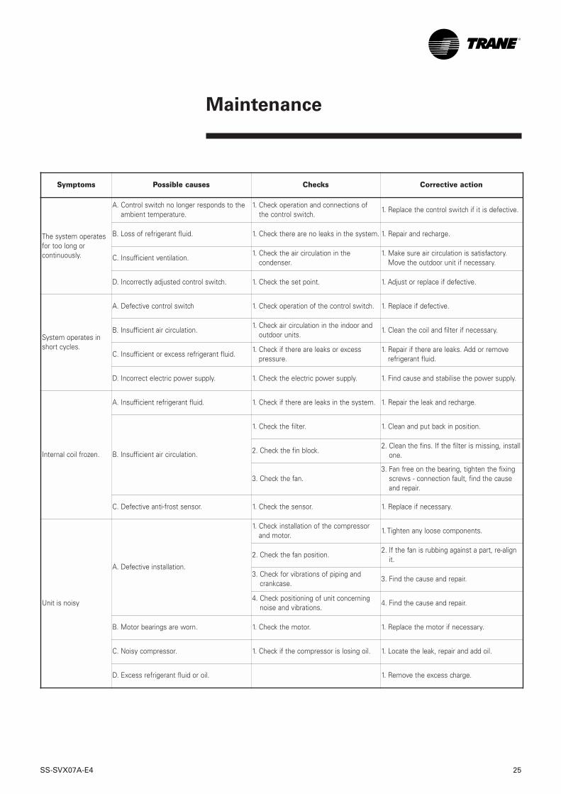
Symptoms Possible causes Checks Corrective action
The system operatesfor too long orcontinuously.
A. Control switch no longer responds to theambient temperature.
1. Check operation and connections ofthe control switch.
1. Replace the control switch if it is defective.
B. Loss of refrigerant fluid. 1. Check there are no leaks in the system. 1. Repair and recharge.
C. Insufficient ventilation. 1. Check the air circulation in the
condenser.1. Make sure air circulation is satisfactory.
Move the outdoor unit if necessary.
D. Incorrectly adjusted control switch. 1. Check the set point. 1. Adjust or replace if defective.
System operates inshort cycles.
A. Defective control switch 1. Check operation of the control switch. 1. Replace if defective.
B. Insufficient air circulation.1. Check air circulation in the indoor and
outdoor units.1. Clean the coil and filter if necessary.
C. Insufficient or excess refrigerant fluid. 1. Check if there are leaks or excess
pressure. 1. Repair if there are leaks. Add or remove
refrigerant fluid.
D. Incorrect electric power supply. 1. Check the electric power supply. 1. Find cause and stabilise the power supply.
Internal coil frozen.
A. Insufficient refrigerant fluid. 1. Check if there are leaks in the system. 1. Repair the leak and recharge.
B. Insufficient air circulation.
1. Check the filter. 1. Clean and put back in position.
2. Check the fin block. 2. Clean the fins. If the filter is missing, install
one.
3. Check the fan.3. Fan free on the bearing, tighten the fixing
screws - connection fault, find the causeand repair.
C. Defective anti-frost sensor. 1. Check the sensor. 1. Replace if necessary.
Unit is noisy
A. Defective installation.
1. Check installation of the compressorand motor.
1. Tighten any loose components.
2. Check the fan position. 2. If the fan is rubbing against a part, re-align
it.
3. Check for vibrations of piping andcrankcase.
3. Find the cause and repair.
4. Check positioning of unit concerningnoise and vibrations.
4. Find the cause and repair.
B. Motor bearings are worn. 1. Check the motor. 1. Replace the motor if necessary.
C. Noisy compressor. 1. Check if the compressor is losing oil. 1. Locate the leak, repair and add oil.
D. Excess refrigerant fluid or oil. 1. Remove the excess charge.
26 SS-SVX07A-E4
Table 15 - Trouble-shooting (electric heating only)
Trouble-shooting
(electric heating only)
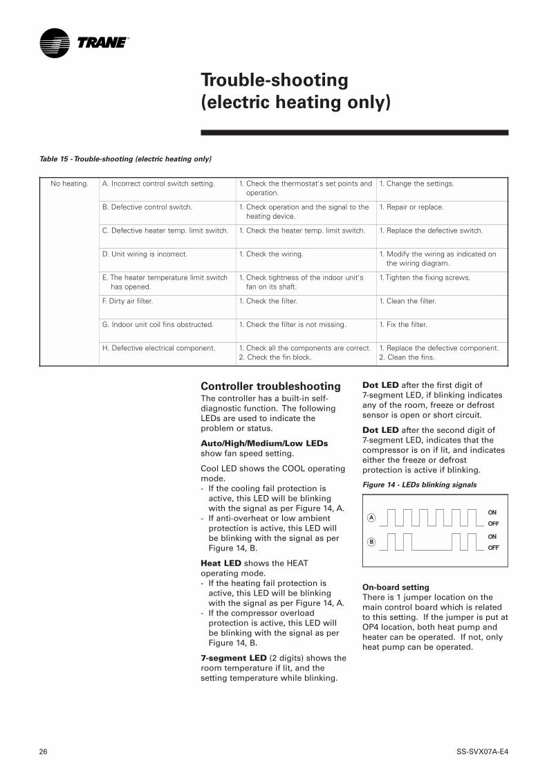
Controller troubleshootingThe controller has a built-in self-diagnostic function. The followingLEDs are used to indicate theproblem or status.
Auto/High/Medium/Low LEDsshow fan speed setting.
Cool LED shows the COOL operatingmode. - If the cooling fail protection is
active, this LED will be blinkingwith the signal as per Figure 14, A.
- If anti-overheat or low ambientprotection is active, this LED willbe blinking with the signal as perFigure 14, B.
Heat LED shows the HEAToperating mode.- If the heating fail protection is
active, this LED will be blinkingwith the signal as per Figure 14, A.
- If the compressor overloadprotection is active, this LED willbe blinking with the signal as perFigure 14, B.
7-segment LED (2 digits) shows theroom temperature if lit, and thesetting temperature while blinking.
Dot LED after the first digit of 7-segment LED, if blinking indicatesany of the room, freeze or defrostsensor is open or short circuit.
Dot LED after the second digit of 7-segment LED, indicates that thecompressor is on if lit, and indicateseither the freeze or defrostprotection is active if blinking.
Figure 14 - LEDs blinking signals
On-board setting
There is 1 jumper location on themain control board which is relatedto this setting. If the jumper is put atOP4 location, both heat pump andheater can be operated. If not, onlyheat pump can be operated.
No heating. A. Incorrect control switch setting. 1. Check the thermostat's set points andoperation.
1. Change the settings.
B. Defective control switch. 1. Check operation and the signal to theheating device.
1. Repair or replace.
C. Defective heater temp. limit switch. 1. Check the heater temp. limit switch. 1. Replace the defective switch.
D. Unit wiring is incorrect. 1. Check the wiring. 1. Modify the wiring as indicated onthe wiring diagram.
E. The heater temperature limit switchhas opened.
1. Check tightness of the indoor unit'sfan on its shaft.
1. Tighten the fixing screws.
F. Dirty air filter. 1. Check the filter. 1. Clean the filter.
G. Indoor unit coil fins obstructed. 1. Check the filter is not missing. 1. Fix the filter.
H. Defective electrical component. 1. Check all the components are correct.2. Check the fin block.
1. Replace the defective component.2. Clean the fins.

SS-SVX07A-E4 27
Notes

Safety recommendationsTo avoid accidents and damage, thefollowing recommendations shouldbe observed during maintenanceand service visits :1. Never apply pressure higher than
7 bar for tests.2. Disconnect the main supply
before any servicing on the unit.3. Service work on the refrigeration
system and the electrical systemshould be carried out only byqualified and experiencedpersonnel.
Maintenance contractIt is strongly recommended that yousign a maintenance contract withyour local Service Agency. Thiscontract provides regularmaintenance of your installation bya specialist in our equipment.Regular maintenance ensures thatany malfunction is detected andcorrected in good time andminimizes the possibility thatserious damage will occur. Finally,regular maintenance ensures themaximum operating life of yourequipment. We would remind youthat failure to respect theseinstallation and maintenanceinstructions may result in immediatecancellation of the warranty.
TrainingThe equipment described in thismanual is the result of many yearsof research and continuousdevelopment. To assist you inobtaining the best use of it, andmaintaining it in perfect operatingcondition over a long period of time,the constructor has at your disposala refrigeration and air conditioningservice school. The principal aim ofthis is to give operators andmaintenance technicians a betterknowledge of the equipment theyare using, or that is under theircharge. Emphasis is particularlygiven to the importance of periodicchecks on the unit operatingparameters as well as on preventivemaintenance, which reduces the costof owning the unit by avoidingserious and costly breakdown.
American Standard Europe BVBARegistered Office: 1789 Chaussée de Wavre, 1160 Brussels - Belgium.
www.trane.comFor more information, contact your local district office or e-mail us [email protected]
Trane has a policy of continuous product and product data improvement and reserves the right tochange design and specifications without notice.Only qualified technicians should perform the installation and servicing of equipment referred to inthis publication..
Literature Order Number SS-SVX07A-E4
Date 0606
Supersedes SS-SVX07A-E4_0604
Stocking Location Europe