Embed Size (px)
Citation preview

CSM_G7TC_DS_E_2_1
1
I/O Relay Terminal
G7TCSingle Cable Connection to PLC Means Space is Saved and Less Control Panel Wiring is Required.• Compact size: 182 (W) ✕ 85 (D) ✕ 68 (H) mm
(8-point Output Block width is 102 mm).• Connects to the PLC through the connecting cable (G79
Series) and connector, and requires only a snap-in operation.• Surge suppressor circuit built-in.• Immediate recognition of I/O signal status using LED
operation indicators.• G3TA I/O Solid-state relay can be mounted instead of G7T.• Mounts easily on a DIN track.• Approved by UL, CSA (except for G7TC-OC16-1).
Ordering InformationI/O Relay Terminal
Note: When ordering, add the rated coil voltage to the model number.Example: G7TC-ID16
* Not approved by UL, CSA.
Accessories (Order Separately)Cable for I/O Relay Terminals XW2Z-R• Cable with Loose Wire and Crimp Terminals: XW2Z-RY@C• Cable with Loose Wires: XW2Z-RA@C• Cable with connectors
• Fujitsu connectors (1:1): XW2Z-R@C(1:2): XW2Z-RI@C-@
XW2Z-RO@C-@(1:3): XW2Z-R@C-@-@
• MIL connectors (1:1): XW2Z-RI@CXW2Z-RO@C
(1:2): XW2Z-RI@-@-D@XW2Z-RM@-@-D@XW2Z-RO@-@-D1
Refer to Connecting Cables on page 12 for details.
Short Bar
Output Short-Circuit Module
Socket
Mounted Relays and I/O Terminal SocketsMounted Relays (G7T I/O Relays and G3TA I/O SSRs)I/O Terminal Sockets (P7TF-IS16/OS16/OS08)Refer to Safety Precautions on page 11 for details.
Indicator Module (With Surge Suppressing Function)
Note: 1. Order the indicator module suitable for the relay coil voltage.2. The indicator module for DC relays can be used with a 12-
V or 24 V DC power supply.
Accessories for DIN Track MountingRefer to your OMRON website for details on the PFP-@.
I/O classification I/O points Internal I/O common Rated voltage Model
Input 16 NPN (– common)
12 VDC
G7TC-ID1624 VDC
100 (110) VDC
100 (110) VACG7TC-IA16
200 (220) VAC
Output
16
NPN (+ common)12 VDC
G7TC-OC1624 VDC
PNP (– common)12 VDC
G7TC-OC16-1 *24 VDC
8 NPN (+ common)12 VDC
G7TC-OC0824 VDC
For the most recent information on models that have been certified for safety standards, refer to your OMRON website.
When your order, specify the rated voltage.
24 VDCRated coil voltage
ModelG78-04
ModelG77-S
ModelP7TF-05
Model Applicable relay coil voltage Remarks
For AC relay P70A100 (110) V AC
Varistor surge suppression200 (220) V AC
For DC relay P70D 12/24 V DC Diode surge suppression
G7TC
2
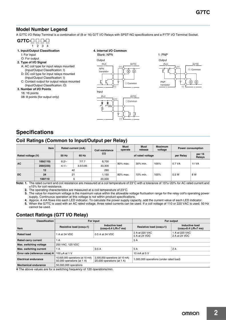
Model Number LegendA G7TC I/O Relay Terminal is a combination of (8 or 16) G7T I/O Relays with SPST-NO specifications and a P7TF I/O Terminal Socket.
SpecificationsCoil Ratings (Common to Input/Output per Relay)
Note: 1. The rated current and coil resistance are measured at a coil temperature of 23°C with a tolerance of 15%/-20% for AC rated current and ±15% for coil resistance.
2. The operating characteristics are measured at a coil temperature of 23°C.3. The value for maximum voltage is the maximum value within the allowable voltage fluctuation range for the relay coil’s operating power
supply. Continuous operation at this voltage is not within product specifications.4. Approx. 4 mA flows into each LED indicator. To calculate the power supply capacity, add the current value of each LED indicator.5. When the G7TC is used with an AC rated voltage, three rated currents can be used. If a coil voltage of 110 or 220 VAC is used, 50 Hz
cannot be used.
Contact Ratings (G7T I/O Relay)
* The above values are for a switching frequency of 120 operations/min.
Item Rated current (mA)Coil resistance
(Ω)
Mustoperate
Mustrelease
Maximumvoltage Power consumption
Rated voltage (V) 50 Hz 60 Hz of rated voltage per Relay per 16Relays
AC100/(110) 8.2/– 7/7.7 8,700
80% max. 30% min. 105% 0.7 VA 11 VA200/(220) 4.1/– 3.5/3.85 33,300
DC
12 42 290
80% max. 10% min. 105% 0.5 W 8 W24 21 1,150
100/110 5 20,000
G7TC-@ @ @-@1 2 3 4
1. Input/Output ClassificationI: For inputO: For output
2. Type of I/O SignalA: AC coil type for input relays mounted
(Input/Output Classification: I)D: DC coil type for input relays mounted
(Input/Output Classification: I)C: Contact output for output relays mounted
(Input/Output Classification: O)3. Number of I/O Points
16: 16 points08: 8 points (for output only)
4. Internal I/O CommonBlank: NPN 1: PNP
X XNPNtransistor
PLC G7TC(+)
(-)Common
PLC G7TC(+)
(-)
Common
X XPNPtransistor
PLC G7TC(+)
(-)
Common
Output Output
Input
Classification For input For output
Item Resistive load (cosφ=1) Inductive load(cosφ=0.4 L/R=7 ms) Resistive load (cosφ=1) Inductive load
(cosφ=0.4 L/R=7 ms)
Rated load 1 A at 24 VDC 0.5 A at 24 VDC 2 A at 220 VAC5 A at 24 VDC
1 A at 220 VAC2 A at 24 VDC
Rated carry current 1 A 5 A
Max. switching voltage 250 VAC, 125 VDC
Max. switching current 1 A 0.5 A 5 A 2 A
Error rate (reference value) * 100 μA at 1 V 10 mA at 5 V
Electrical endurance 10,000,000 operations (at 10 mA)50,000 operations (at 1 A)
2,500,000 operations (at 10 mA)20,000 operations (at 1 A) 1,000,000 operations (under rated load)
Mechanical endurance 50,000,000 operations

3
G7TC
Characteristics
Note: The above values are initial values.*1. Measurement: 1 A at 5 VDC.*2. Ambient temperature: 23°C.*3. This is between connector pin No. 10 and 20, and between connector pin No. 9 and 19.*4. Connecting cables up to 5 m are available as standard products. For longer cables, enquire separately.
UL and CSA StandardsStandard G7TC I/O Relay Terminal, except for the G7TC-OC16-1 and the G7TC-OC08, have met UL and CSA standards (UL file no. E95399; CSA file no. LR35535).Note that the following UL- and CSA-qualifying ratings differ from the performance characteristics of the individual models:
ItemModel G7TC-IA16
(Input, AC coil)G7TC-ID16
(Input, DC coil)G7TC-OC16 (–1)(output, DC coil)
G7TC-OC08(output, DC coil)
Contact form SPST-NO × 16 SPST-NO × 8
Contact mechanism Bifurcated crossbar contact Single contact
Contact material Au cladding + Ag AgInSn
Contact resistance *1 50 mΩ max.
Must Operate time *2 15 ms max.
Release time *2 15 ms max.
Max. switching frequency
Mechanical limit 18,000 operations/h
At rated load 1,800 operations/h
Insulation resistance 100 MΩ (at 500 VDC)
Dielectric strength
Between coil and contact 2,000 VAC, 50/60 Hz for 1 minute
Between same polarity contacts 1,000 VAC, 50/60 Hz for 1 minute
Between paired connectors *3 250 VAC, 50/60 Hz for 1 minute
Vibration resistance 10 to 55 to 10 Hz with 0.5-mm single amplitude (1.0-mm double amplitude)
Shock resistance 200 m/s2
Noise immunity Noise level: 1.5 kV; pulse width: 100 ns to 1 μs
Rated voltage between positive and negative terminal blocks Rated voltage of controller’s (PLC or other) input circuit 12 VDC ±5%
24 VDC ±5%
Rated current between positive and negative terminal blocks
Input circuit current of controller (PLC or other) ✕ number of ON points
12 VDC: 46 mA ✕ number of ON points24 VDC: 25 mA ✕ number of ON points
Cable length *4
To controller 5 m max. (reference value)
To I/O devices 50 m max. (reference value, for 2-mm2 CVV cable) Dependent on load
Ambient operating temperature 0 to 55°C
Ambient operating humidity 35% to 85% (with no icing or condensation)
Tightening torque for external connections 0.78 to 1.18 N·m
Tensile strength No damage when a tensile force of 49 N is applied in each direction.In the direction of the track, the tensile strength is 9.8 N min.
I/O terminal tightening torque Tightening strength: 0.98 N·m; Tensile strength 49 N per minute
LED color Red Green
Case color Transparent red Transparent green Transparent green
Coil surge absorber Varistor Diode (1 A, 1,000 V)
Weight Approx. 640 g Approx. 630 g Approx. 670 g Approx. 350 g
Model Coil ratings Contact ratings
G7TC-ID16, G7TC-IA16 10 mA/point, 24 VDC 250 VAC max.
G7TC-OC16 Coil drive current, 24 VDCInductive load: 10 A, 250 VACResistive load: 10 A, 30 VDCRated horsepower: 1/2 HP, 240 VAC

G7TC
4
Engineering Data (Reference Value)
Life Expectancy of Output Max. Switching capacity of Output(Life expectancy: 1,000,000 operations)
Life Expectancy of Input
Note: These data are actual measured values that were sampled from the production line and prepared in graph format, and are for reference purposes only. A relay is manufactured by mass production, and as a basic rule must be used with allowance made for a certain amount of deviation.
Example for Output Block(for Reference)If a G7T I/O Relay is mounted in every other position on an Output Block (see drawing), a resistive load of 10 A (24 VDC) can be switched. Note that the service life is reduced to 150,000 operations in this case.
Load Current vs. Ambient TemperatureG3TA-OA202SZG3TA-OA202SLG3TA-ODX02S G3TA-OA201S
Inrush CurrentThe following graphs show the maximum inrush currents that can be withstood for non-repetitive operation. For repetitive operation, the figures should be reduced by half.
G3TA-OA202SZG3TA-OA202SL
G3TA-ODX02SG3TA-OD201S
Switched current (A)
1
357
10
305070
100
300500700
1,000
3,0005,000
0 1 2 3 4 5 6 7 8
220 VAC (cosφ 0.4)
24 VDC, L/R=7 ms
24 VDC, resistive load
220 VAC, resistive load
(� 1
04 op
erat
ions
)
0.01
0.030.05
0.1
0.30.5
1
35
10
30
50
1 3 5 10 30 50 100 300 500 1,000
Voltage (V)
AC resistiveload
Ope
ratin
g cu
rren
t (A
)
DC inductive load,L/R = 7 ms
DC resistive load
AC inductive load (cosφ 0.4)
1
35710
305070100
3005007001,000
3,0005,000
0 10 mA 50 mA 100 mA 0.5 A 1 A
24 VDC, L/R=7 ms
24 VDC,resistive load
Switched current (mA range)
Switched current (A range)
(� 1
04 op
erat
ions
)
G7T (10 A) G7T (0.1 A max.)
3.0
2.5
2.0
1.5
1.0
0.5
0100806040200-20-30
Single relay
16 points mounted
Load
cur
rent
(A
)
Ambient temperature (°C)
3.0
2.5
2.0
1.5
1.0
0.70.5
0100806040200-20-30
Single relay
16 points mounted
Load
cur
rent
(A
)
Ambient temperature (°C)
Energizing time (ms)
Inru
sh c
urre
nt (
A: P
eak)
10 30 50 100 200 500 1,000 5,0000
20
10
30
10 30 50 100 300 500 1,000 2,000012
34
56
7
8
9
1011
1213
1415
G3TA-OD201S
G3TA-ODX02S
Energizing time (ms)
Inru
sh c
urre
nt (
A: P
eak)

5
G7TC
Internal Circuits
Note: Pin numbers are indicated for convenience. The ▲ mark can be used to determine orientation.
Cable LengthThe following graph gives reference values for the relationship between cable length and voltage in the case where the voltage fluctuation of the power supply is 5%.
0
20
21
22
23
24
20 40 60 80 100 120
Vol
tage
(V
)
0.3-V drop in voltage indirection of diode toblock reverse current
Rated voltage
Measured data when rated voltage(24 V) applied
Length of power line (AWG 28) (m)
Rated voltage (measured data) – 5%
Lower limit of voltage for relayuse – 10%
5%
G7TC-ID16 (NPN input/– common)
01234567+−
89101112131415+−
1
2
3
4
5
6
7
8
9
10
11
12
13
14
15
16
17
18
19
20
Connector pin No.mark
I/O indications on Screw Terminals
+
−
X
0
C0
X
1
C1
X
2
C2
X
3
C3
X
4
C4
X
5
C5
X
6
C6
X
7
C7
X
8
C8
X
9
C9
X
10
C10
X
11
C11
X
12
C12
X
13
C13
X
14
C14
X X
15
C15
+Screw terminals−
Input relaysG7T-1122S
10
20
12345678
1112131415161718
919
Connectorpin No.
Connector Pin ConfigurationTop View
G7TC-IA16 (NPN input/– common)
01234567+−
89101112131415+−
1
2
3
4
5
6
7
8
9
10
11
12
13
14
15
16
17
18
19
20
Connector pin No.mark
I/O indications on Screw Terminals
X
0
C0
1
C1
2
C2
3
C3
4
C4
5
C5
6
C6
7
C7
8
C8
9
C9
10
C10
11
C11
12
C12
13
C13
14
C14
X
15
C15
10
20
12345678
1112131415161718
919
X X X X X X X X X X X X X X X Input relaysG7T-1122S
Connectorpin No.
+
−
Screw terminals
Connector Pin ConfigurationTop View

G7TC
6
Note: Pin numbers are indicated for convenience. The ▲ mark can be used to determine orientation.
G7TC-OC16 (NPN output/+ common)Note: A controller with an NPN transistor, common output can be connected to the G7TC-OC16.
01234567−+
89101112131415−+
1
2
3
4
5
6
7
8
9
10
11
12
13
14
15
16
17
18
19
20
Connector No.mark
I/O indications on Screw Terminals
0
C0
1
C1
2
C2
3
C3
4
C4
5
C5
6
C6
7
C7
8
C8
9
C9
10
C10
11
C11
12
C12
13
C13
14
C14
15
C15
Screw terminals
X12345678
11121314151617181020
919
XX X X X X X X X X X X X X X X Output relaysG7T-1112S
Connectorpin No.
+
−
Connector Pin ConfigurationTop View
G7TC-OC16-1 (PNP output/- common)Note: A controller with a PNP transistor, + common output can be connected to the G7TC-OC16-1.
Do not connect the G71 Remote Interface to the G7TC-OC16-1. Due to the difference in polarity, the G71 will be damaged if the G7TC-OC16-1 and the G71 are connected to each other. Use the G7TC-OC16 (NPN output/+ common) instead, to connect to the G71.The reception of orders for G71 Remote Interface was discontinued at the end of March 2012.
01234567+−
I/O indications on Screw Terminals
89101112131415+−
1
2
3
4
5
6
7
8
9
10
11
12
13
14
15
16
17
18
19
20
Connector No.mark
0
C0
1
C1
2
C2
3
C3
4
C4
5
C5
6
C6
7
C7
8
C8
9
C9
10
C10
11
C11
12
C12
13
C13
14
C14
15
C15
X12345678
11121314151617181020
919
XX X X X X X X X X X X X X X X
Screw terminals
Output relaysG7T-1112S
Connectorpin No.
+
−
Connector Pin ConfigurationTop View
G7TC-OC08 (NPN output/+ common)Note: A controller with an NPN transistor, -common output can be connected to the G7TC-OC08.
01234567−+
1
2
3
4
5
6
7
8
9
10
11
12
13
14
15
16
17
18
19
20
I/O indications on Screw Terminals
Connector No.mark
+
−
0
C0
1
C1
2
C2
3
C3
4
C4
5
C5
6
C6
7
C7
X12345678
1020
919
XX X X X X X X
Screw terminals
Output relaysG7T-1112S
Connectorpin No.
Connector Pin ConfigurationTop View

7
G7TCDimensions (Unit: mm)
I/O Relay Terminal
G7TC-ID16G7TC-IA16
182
Thirty-six,M3.5
3426
108
85
68
35.3+0.20
21
32.5
G7TC-OC16G7TC-OC16-1
182
108
85
68
21
32.5
Thirty-six,M3.5 35.3+0.2
0
G7TC-OC08102
108
85
68
Twenty,M3.5 35.3+0.2
0
21
32.5

G7TC
8
Accessories (Order Separately)
Short BarG78-04 Use this piece for short-circuiting across terminals.Max. current flow: 20 A
4.5
12.513.3
R1.8
R1.0 37.8
2.510 10 10
7.8 0 −0.1
3.6 0 −0.1
Output Short-Circuit ModuleG77-S The output of the I/O Relay Terminal can be obtained without relays through the G77-S Output Short-Circuit Module. Note that the G77-S Output Short-Circuit Module is not available for inputs.
32 max.39 max.
1.62.4 0.5
29 max.33.5 max.
10 max. 4
Four, 1-dia. holes
3.15
10 max.
15±0.13
4
1 5
Terminal Arrangement/Internal Connections (Bottom View)
(There is no coil polarity.)
SocketP7TF-05 The G7T (SPST-NO, SPST-NC, and SPDT types) and the G3TA I/O Relays can be mounted on the P7TF-05 Socket.The P7TF-05 can be used for applications involving sequences that require slim relays, or to enable use of SPDT relays with the I/O Relay Terminal. To use part of the I/O Relay Terminal with SPDT specifications, insert an Output Short-Circuit Module into the I/O Relay Terminal, and use the P7TF-05 Socket in combination with an SPDT Relay for the Module’s output.
12.5±0.2
62±0.1
4 dia. or M3
19 max.
71.5 max.
4
12.5±0.2
59 max.
19.5
9
35.5
Five, M3.5�8Screw with square washer7
4
23
1
5
Internal Connections(Top View)
Mounting Hole Dimensions
Note: Terminal 1 is positive when the G3TA or Indicator Module is employed.
Note: Terminal 1 is positive when the I/O SSR is employed.
Specifications
Contact resistance 10 mΩ max.(measured at 5 V DC, 1 A)
Dielectric strength 2,000 VAC for 1 minute
Insulation resistance 1,000 MΩ min. (at 500 V)
Vibration resistance 10 to 55 to 10 Hz, 0.5 mm single amplitude (1.0 mm double amplitude)
Shock resistance 1,000 m/s2
Ambient temperature Operating: -40 to 70°C (with no icing or condensation)
Ambient humidity 5% to 85%
Weight Approx. 28 g
Indicator Module (With Surge Suppressing Function)P70@Remove the transparent style strip of the P7TF-05 socket and mount this module and it will function as an operation indicator with the surge suppression.
29.5 max.
32.5 max.39 max.
200.5
1.6
Two, 1-dia.holes
2.6
8.5 max.
(+) (−)DC
P70D (DC relays)
AC
P70A (AC relays)
Internal Connection
(There is no coil polarity for AC relays.)

9
G7TCTerminal Arrangement / Terminal Connection Example
InputG7TC-ID16G7TC-IA16
• Supply power to terminals 0 through 15 and C0 through C15 according to the voltage specifications of the I/O Relays and I/O Relay Terminal. Do not reverse positive and negative terminals on the DC Input Block (0 through 15 are positive; C0 through C15, negative). Short Bar is available.
• Supply to the power terminal (positive and negative) the rated voltage of the controller’s input circuits (24 VDC or 12 VDC). Use a low-noise power source.
• When using a Connecting Cable with two connectors, be sure to use the Cable for Input Blocks. Using the Cable for Output Blocks may result in malfunction or damage to the product.Connecting Cable: XW2Z-RTape Color: Red
Rail hooks
Label (red)
ConnectorInput RelayG7T-1122S Relay hook
Input TerminalP7TF-IS16
LED DC Input: GreenAC Input: Red
+ 0 1 2 3 4 5 6 7 8 9 10 11 12 13 14 15
− C0 C1 C2 C3 C4 C5 C6 C7 C8 C9 C10 C11 C12 C13 C14 C15
DC for the G7TC-ID16;AC for the G7TC-IA16.Use at the rated voltage for the G7TC.Independent Common Possible.
24 VDC or12 VDC (Differ in models.)
External connections
OutputG7TC-OC16(-1)G7TC-OC08
• There are voltage specifications for the Relays and Terminals. Depending on the controller connected, select either 12 or 24 VDC.
• Supply power to contact output terminals 0 through 15 and C0 through C15 according to the requirements of the loads. A 4 terminal Short Bar is available.
• Supply to the power terminals (positive and negative) power both for driving the relays and for controller output transistors. Match the controller and I/O Relay Terminal voltage specifications. Use a low- noise power source.
• When using a Connecting Cable with two connectors, be sure to use the Cable for Output Blocks. Using the Cable for Input Blocks may result in malfunction or damage to the product.Connecting Cable: XW2Z-R Tape Color: Yellow
• Output Block Unit G7TC-OC08 does not have terminals 8 through 15 and C8 through C15. Although a 20-pin connector is used, pins 11 through 18 are not connected.
• When an I/O SSR (G3TA-OD@@) is mounted, terminals 0 to 15 will be positive.
Connector
Rail hooks
Label (yellow)
Output Relay(G7T-1112S)
LED (green) Relay hookOutput Terminal(P7TF-OS16)
+ 0 1 2 3 4 5 6 7 8 9 10 11 12 13 14 15
− C0 C1 C2 C3 C4 C5 C6 C7 C8 C9 C10 C11 C12 C13 C14 C15
AC (DC possible; Independent Common also possible)
L0 L1 L2 L3 L4 L5 L6 L7 L8 L9 L10 L11 L12 L13 L14 L15
24 VDC or12 VDC (Differ in models.)
External connections

G7TC
10
Connection Example for SPDT RelaysThe following is an application example for the P7TF-05 using an SPDT Relay on a terminal of the G7TC-@@16(-1).
Note: If more than one G77-S Output Short-Circuit Module is employed, the voltage output of the terminals on the G7TC is as follows:G7TC-OC16: The positive side (the lower row) connects to the common line internally.G7TC-OC16-1: The negative side (the upper row) connects to the common line internally.
+ 0 1 2 3 4 5 6 7 8 9 10 11 12 13 14 15
− C0 C1 C2 C3 C4 C5 C6 C7 C8 C9 C10 C11 C12 C13 C14 C15
AC (DC possible; Independent Common also possible)
L0 L1 L2 L3 L4 L5 L6 L7 L8 L9 L10 L11 L12 L13 L14
L16
4
23
1
5
L15
G7T(SPDT)
P7TF-05
NO contact
NO contact load SPDT contact load
NC contact
G7TC
G7T (SPST-NO)24 VDC or12 VDC (Differ in models.) * Use the G77-S Output Short-Circuit Module in place of the G7T I/O Relay.
With the G77-S voltage output is available between terminals 15 and C15.The maximum current is determined according to the controller.

11
G7TCSafety PrecautionsBe sure to read the Safety Precautions for All I/O Relay Terminals in the website at: http://www.ia.omron.com/.GeneralI/O Relays and I/O Relay Terminal can be combined as follows to form I/O Relay Terminal:
*1. These are the I/O Relays mounted on the G7TC I/O Relay Terminal.*2. To use I/O SSRs, remove the I/O Relays and mount the I/O SSRs to the slots where the I/O Relays were mounted. Or, order and combine a
P7FT I/O Terminal and I/O SSRs.*3. The P7TF I/O Terminal provides only sockets. It does not have Relays mounter to it. Mount I/O Relays or I/O SSRs to the sockets. Specify the
rated voltage in the same way as when ordering the G7TC I/O Relay Terminal.
• Combinations of AC Input Relays/SSRs and DC Input Relays/SSRs cannot be used with the same Terminal. This is because specifications for coil surge suppression elements are different.Relays/SSRs with different voltage specifications cannot be used with the same Terminal. (For example, a 100-VAC Input Relay and a 200-VAC Input Relay, or a 12-VDC Output Relay and a 24-VDC Output Relay cannot be used with the same Terminal.)This is because specifications of operation indicator circuits are different.
• Only use I/O Terminals, I/O Relays, and I/O SSRs with the same specifications for rated voltage.
• I/O Relay Terminal are color coded, as shown below, according to input/output and AC/DC specifications.
• Both Input and Output Blocks do not have internal power supplies. For an Output Block, supply the relay drive power to the positive and negative terminals (either 12 or 24 VDC). Loads (terminal contacts 0 through 15) must also be supplied with appropriate power. For an Input Block, supply, to the positive and negative terminals, power for input signals to the controller.
• The same Connecting Cable, XW2Z-RY, is used for the G7TC-OC08 eight-point Output Block as for other I/O Relay Terminal; leave 8 points unconnected.
• Indicators indicate the presence or absence of signals.Use the display lever inside each relay for fault diagnosis. (Some relays do not have this lever depending on the specifications.)
• Each relay must be pressed down until its hold-down hooks engage completely. Heating or malfunction can result if relays are not mounted properly.
• Unlabeled terminals are not electrically connected. Use these for repeater terminals.
• Indicator positions and relay orientation differ between Input and Output Blocks. This is to aid in differentiating Input Blocks from Output Blocks and in following signal flow.
• DC Input Blocks and Output Blocks with G3TA-OD@@@@ have positive and negative terminals, with the positive terminals normally being on the top of the I/O Relay Terminal. Reversing positive and negative terminals will prevent operation.
• DIN tracks are generally used to mount I/O Relay Terminal. For screw mounting, a 210-mm DIN track is available that can be used as an adapter in combination with End Plates (PFP-M, two required).
• A Short Bar is provided to connect four terminals. The current capacity of the Short Bar is 20 A. As long as this current capacity is not exceeded, the Short Bar can be used in combination as shown at the right to connect more than four terminals.
• Special Connecting Cables are provided for connections to OMRON PLC I/O Units with Connectors. Connecting Cables with two connectors, however, come in two types: Cables for Input Blocks (XW2Z-R) and Cables for Output Blocks (XW2Z-R).Be sure to purchase the correct Cable for the application.
Microload SwitchingInput Relays (DC coil type) and I/O SSRs (DC input type) can be mounted onto an Output Block. Doing so enables using controller programming to simultaneously switch on or off two outputs (DPST-NO operation) to switch a SPST-NO load that in turn switches another SPST-NO load. One configuration for this is shown below.
I/O Relay Terminal I/O Relay I/O SSR *2 I/O Terminal (Socket) *3DC input G7TC-ID16
G7T-1122S *1DC G3TA-IDZ002 (M) P7TF-IS16 (DC type)
AC input G7TC-IA16 AC G3TA-IAZR02S P7TF-IS16 (AC type)
DC outputG7TC-OC16G7TC-OC16-1G7TC-OC08
G7T–1112S (SPST-NO type) *1G7T–1012S (SPST-NC type)
AC G3TA-OA202SZG3TA-OA202SL P7TF-OS16
P7TF-OS16-1P7TF-OS08DC G3TA-ODX02S
G3TA-OD201S
I/O Terminallabel
I/O Terminalindicators
I/O Relaycase
for InputDC Red Green Green
AC Red Red Red
for Output DC Yellow Green Transparent
Switching signal to motor,heater, valve, etc.
Input signal to controller,electronic device, etc.
G7T-1122SInput Relay(DC coil)G3TA-IDInput SSR(DC Input)
Output Relayor I/O SSR
I/O Terminal SocketP7TF-OS16(-1)P7TF-OS08PLC

G7TC
12
Connecting CablesRefer to XW2Z-R Cables for I/O Relay Terminals (Cat. No. G126) for details on the Connecting Cables.
Type Name I/O Classification Appearance Cable length L (mm) Models
Various devices
Cables with Loose Wires and Crimp Ter-minals
XW2Z-RY C
16 I/O points
1,000 XW2Z-RY100C
1,500 XW2Z-RY150C
2,000 XW2Z-RY200C
3,000 XW2Z-RY300C
5,000 XW2Z-RY500C
Cables with Loose Wires
XW2Z-RA C
16 I/O points
2,000 XW2Z-RA200C
5,000 XW2Z-RA500C
Fujitsu connectors (24 pins)
Cables with Connec-tors (1:1)
XW2Z-R C
16 I/O points
1,000 XW2Z-R100C
1,500 XW2Z-R150C
2,000 XW2Z-R200C
3,000 XW2Z-R300C
5,000 XW2Z-R500C
Fujitsu connectors (40 pins)
Cables with Connec-tors (1:2)
XW2Z-RI C-XW2Z-RO C-
32 input points
(A) 1,000 (B) 750 XW2Z-RI100C-75
(A) 1,500 (B) 1,250 XW2Z-RI150C-125
(A) 2,000 (B) 1,750 XW2Z-RI200C-175
(A) 3,000 (B) 2,750 XW2Z-RI300C-275
(A) 5,000 (B) 4,750 XW2Z-RI500C-475
32 output points
(A) 1,000 (B) 750 XW2Z-RO100C-75
(A) 1,500 (B) 1,250 XW2Z-RO150C-125
(A) 2,000 (B) 1,750 XW2Z-RO200C-175
(A) 3,000 (B) 2,750 XW2Z-RO300C-275
(A) 5,000 (B) 4,750 XW2Z-RO500C-475
Fujitsu connectors (56 pins)
Cables with Connec-tors (1:3)
XW2Z-R C- -
48 I/O points
(A)1,500
(B)1,250
(C)1,000 XW2Z-R150C-125-100
(A)2,000
(B)1,750
(C)1,500 XW2Z-R200C-175-150
(A)3,000
(B)2,750
(C)2,500 XW2Z-R300C-275-250
MIL connectors (20 pins)
Cables with Connec-tors (1:1)
XW2Z-RI C,XW2Z-RO C
16 input points250 XW2Z-RI25C
500 XW2Z-RI50C
16 output points250 XW2Z-RO25C
500 XW2Z-RO50C
MIL connectors (40 pins)
Cables with Connec-tors (1:2)
XW2Z-RI - -D1XW2Z-RO - -D1XW2Z-RM - -D1XW2Z-RI - -D2XW2Z-RM - -D2
32 input points(A) 500 (B) 250 XW2Z-RI50-25-D1
(A) 750 (B) 500 XW2Z-RI75-50-D1
32 output points(A) 500 (B) 250 XW2Z-RO50-25-D1
(A) 750 (B) 500 XW2Z-RO75-50-D1
16 input points/16 output points
(A) 500 (B) 250 XW2Z-RM50-25-D1
(A) 750 (B) 500 XW2Z-RM75-50-D1
32 input points(A) 500 (B) 250 XW2Z-RI50-25-D2
(A) 750 (B) 500 XW2Z-RI75-50-D2
16 input points/16 output points
(A) 500 (B) 250 XW2Z-RM50-25-D2
(A) 750 (B) 500 XW2Z-RM75-50-D2
300L
A side B sideDevice end I/O Relay Terminal
300L
L
Straight length (without bends)
(120)
(A)
(B)
(270)
(B)
(C)
Straight length (without bends)
(120)
(A)
L
(B)
Straight length (without bends)
(120)
(A)

13
G7TC
Mitsubishi Electric PLCs with 32-point connectors (1:2)
Applicable models:For inputs: AX42, A1SX41, A1SX42, QX41, and QX42For outputs: AY42, A1SY41, A1SY42, QY41P, and QY42P
Mitsubishi Electric PLC Connecting Cables
XW2Z-RI C- -MNXW2Z-RO C- -MN
32 input points
(A) 1,000 (B) 750 XW2Z-RI100C-75-MN
(A) 1,500 (B) 1,250 XW2Z-RI150C-125-MN
(A) 2,000 (B) 1,750 XW2Z-RI200C-175-MN
(A) 3,000 (B) 2,750 XW2Z-RI300C-275-MN
32 output points
(A) 1,000 (B) 750 XW2Z-RO100C-75-MN
(A) 1,500 (B) 1,250 XW2Z-RO150C-125-MN
(A) 2,000 (B) 1,750 XW2Z-RO200C-175-MN
(A) 3,000 (B) 2,750 XW2Z-RO300C-275-MN
Type Name I/O Classification Appearance Cable length L (mm) Models
(B)Straight length (without bends)
(120)
(A)
A side B sideDevice end I/O Relay Terminal

Terms and Conditions Agreement Read and understand this catalog. Please read and understand this catalog before purchasing the products. Please consult your OMRON representative if you have any questions or comments. Warranties. (a) Exclusive Warranty. Omron’s exclusive warranty is that the Products will be free from defects in materials and workmanship for a period of twelve months from the date of sale by Omron (or such other period expressed in writing by Omron). Omron disclaims all other warranties, express or implied. (b) Limitations. OMRON MAKES NO WARRANTY OR REPRESENTATION, EXPRESS OR IMPLIED, ABOUT NON-INFRINGEMENT, MERCHANTABILITY OR FITNESS FOR A PARTICULAR PURPOSE OF THE PRODUCTS. BUYER ACKNOWLEDGES THAT IT ALONE HAS DETERMINED THAT THE PRODUCTS WILL SUITABLY MEET THE REQUIREMENTS OF THEIR INTENDED USE. Omron further disclaims all warranties and responsibility of any type for claims or expenses based on infringement by the Products or otherwise of any intellectual property right. (c) Buyer Remedy. Omron’s sole obligation hereunder shall be, at Omron’s election, to (i) replace (in the form originally shipped with Buyer responsible for labor charges for removal or replacement thereof) the non-complying Product, (ii) repair the non-complying Product, or (iii) repay or credit Buyer an amount equal to the purchase price of the non-complying Product; provided that in no event shall Omron be responsible for warranty, repair, indemnity or any other claims or expenses regarding the Products unless Omron’s analysis confirms that the Products were properly handled, stored, installed and maintained and not subject to contamination, abuse, misuse or inappropriate modification. Return of any Products by Buyer must be approved in writing by Omron before shipment. Omron Companies shall not be liable for the suitability or unsuitability or the results from the use of Products in combination with any electrical or electronic components, circuits, system assemblies or any other materials or substances or environments. Any advice, recommendations or information given orally or in writing, are not to be construed as an amendment or addition to the above warranty. See http://www.omron.com/global/ or contact your Omron representative for published information. Limitation on Liability; Etc. OMRON COMPANIES SHALL NOT BE LIABLE FOR SPECIAL, INDIRECT, INCIDENTAL, OR CONSEQUENTIAL DAMAGES, LOSS OF PROFITS OR PRODUCTION OR COMMERCIAL LOSS IN ANY WAY CONNECTED WITH THE PRODUCTS, WHETHER SUCH CLAIM IS BASED IN CONTRACT, WARRANTY, NEGLIGENCE OR STRICT LIABILITY. Further, in no event shall liability of Omron Companies exceed the individual price of the Product on which liability is asserted. Suitability of Use. Omron Companies shall not be responsible for conformity with any standards, codes or regulations which apply to the combination of the Product in the Buyer’s application or use of the Product. At Buyer’s request, Omron will provide applicable third party certification documents identifying ratings and limitations of use which apply to the Product. This information by itself is not sufficient for a complete determination of the suitability of the Product in combination with the end product, machine, system, or other application or use. Buyer shall be solely responsible for determining appropriateness of the particular Product with respect to Buyer’s application, product or system. Buyer shall take application responsibility in all cases. NEVER USE THE PRODUCT FOR AN APPLICATION INVOLVING SERIOUS RISK TO LIFE OR PROPERTY OR IN LARGE QUANTITIES WITHOUT ENSURING THAT THE SYSTEM AS A WHOLE HAS BEEN DESIGNED TO ADDRESS THE RISKS, AND THAT THE OMRON PRODUCT(S) IS PROPERLY RATED AND INSTALLED FOR THE INTENDED USE WITHIN THE OVERALL EQUIPMENT OR SYSTEM. Programmable Products. Omron Companies shall not be responsible for the user’s programming of a programmable Product, or any consequence thereof. Performance Data. Data presented in Omron Company websites, catalogs and other materials is provided as a guide for the user in determining suitability and does not constitute a warranty. It may represent the result of Omron’s test conditions, and the user must correlate it to actual application requirements. Actual performance is subject to the Omron’s Warranty and Limitations of Liability. Change in Specifications. Product specifications and accessories may be changed at any time based on improvements and other reasons. It is our practice to change part numbers when published ratings or features are changed, or when significant construction changes are made. However, some specifications of the Product may be changed without any notice. When in doubt, special part numbers may be assigned to fix or establish key specifications for your application. Please consult with your Omron’s representative at any time to confirm actual specifications of purchased Product. Errors and Omissions. Information presented by Omron Companies has been checked and is believed to be accurate; however, no responsibility is assumed for clerical, typographical or proofreading errors or omissions.
2017.1
In the interest of product improvement, specifications are subject to change without notice.
OMRON Corporation Industrial Automation Company http://www.ia.omron.com/
(c)Copyright OMRON Corporation 2017 All Right Reserved.