Embed Size (px)
Citation preview

1
POCSAG Remote Controller & Messaging Receiver
Model No. Y1727RY2 rev 1.30 July 2012.
Operation Manual

2
Wireless Devices Inc. (Taiwan)
The Y1727RY2 series is the high performance VHF/UHF/900MHz paging telemetry
controller, which is specially designed for electric power lines ON-OFF remote control,
car alarm and security alarm applications etc. And the control concept is to utilize thru
either the existed POCSAG paging infrastructure or on-premises paging transmitter to
send out the various 46 message demands.
3
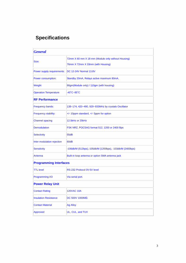
Specifications
General
Size: 72mm X 60 mm X 18 mm (Module only without Housing)
76mm X 72mm X 33mm (with Housing)
Power supply requirements: DC 12-24V Normal 13.8V
Power consumption: Standby 20mA, Relays active maximum 80mA.
Weight 90gm(Module only) / 110gm (with housing)
Operation Temperature -40˚C~85˚C
RF Performance
Frequency bands: 138~174, 420~490, 929~933MHz by crystals Oscillator
Frequency stability: +/- 10ppm standard, +/- 5ppm for option
Channel spacing 12.5kHz or 25kHz
Demodulation FSK NRZ, POCSAG format 512, 1200 or 2400 Bps
Selectivity 55dB
Inter modulation rejection 60dB
Sensitivity -106db/M (512bps),-105db/M (1200bps), -103db/M (2400bps)
Antenna Built-in loop antenna or option SMA antenna jack
Programming Interfaces
TTL level RS-232 Protocol 0V-5V level
Programming I/O Via serial port.
Power Relay Unit
Contact Rating 120VAC 10A
Insulation Resistance DC 500V 1000MΩ.
Contact Material Ag Alloy
Approved UL, CUL, and TUV
4
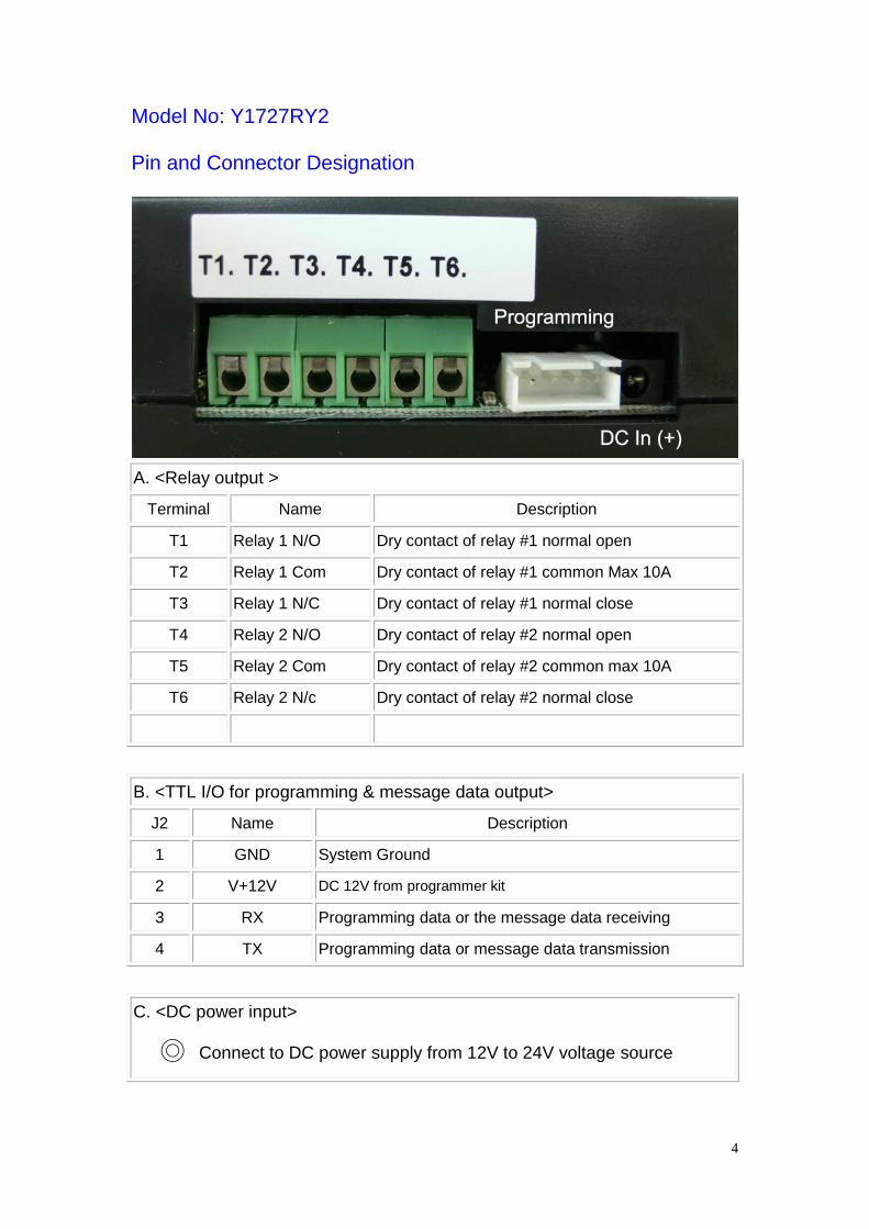
Model No: Y1727RY2
Pin and Connector Designation
A. <Relay output >
Terminal Name Description
T1 Relay 1 N/O Dry contact of relay #1 normal open
T2 Relay 1 Com Dry contact of relay #1 common Max 10A
T3 Relay 1 N/C Dry contact of relay #1 normal close
T4 Relay 2 N/O Dry contact of relay #2 normal open
T5 Relay 2 Com Dry contact of relay #2 common max 10A
T6 Relay 2 N/c Dry contact of relay #2 normal close
B. <TTL I/O for programming & message data output>
J2 Name Description
1 GND System Ground
2 V+12V DC 12V from programmer kit
3 RX Programming data or the message data receiving
4 TX Programming data or message data transmission
C. <DC power input>
Connect to DC power supply from 12V to 24V voltage source
5
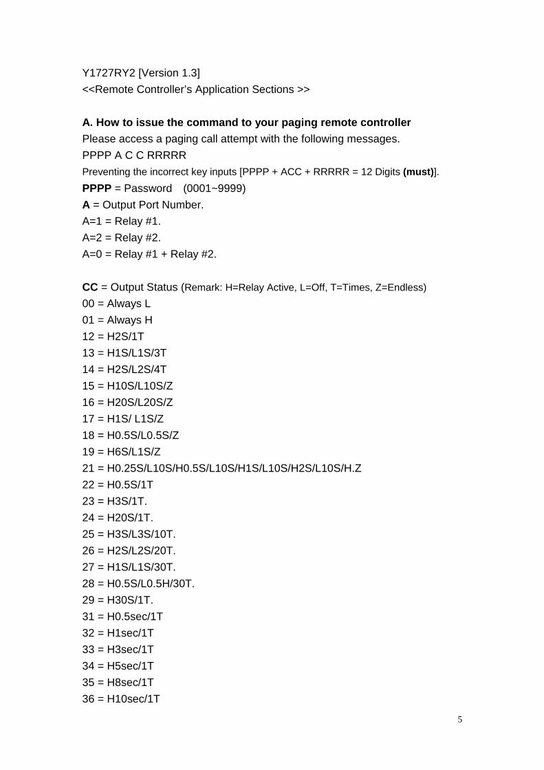
Y1727RY2 [Version 1.3]
<<Remote Controller’s Application Sections >>
A. How to issue the command to your paging remote controller
Please access a paging call attempt with the following messages.
PPPP A C C RRRRR
Preventing the incorrect key inputs [PPPP + ACC + RRRRR = 12 Digits (must)].
PPPP = Password (0001~9999)
A = Output Port Number.
A=1 = Relay #1.
A=2 = Relay #2.
A=0 = Relay #1 + Relay #2.
CC = Output Status (Remark: H=Relay Active, L=Off, T=Times, Z=Endless)
00 = Always L
01 = Always H
12 = H2S/1T
13 = H1S/L1S/3T
14 = H2S/L2S/4T
15 = H10S/L10S/Z
16 = H20S/L20S/Z
17 = H1S/ L1S/Z
18 = H0.5S/L0.5S/Z
19 = H6S/L1S/Z
21 = H0.25S/L10S/H0.5S/L10S/H1S/L10S/H2S/L10S/H.Z
22 = H0.5S/1T
23 = H3S/1T.
24 = H20S/1T.
25 = H3S/L3S/10T.
26 = H2S/L2S/20T.
27 = H1S/L1S/30T.
28 = H0.5S/L0.5H/30T.
29 = H30S/1T.
31 = H0.5sec/1T
32 = H1sec/1T
33 = H3sec/1T
34 = H5sec/1T
35 = H8sec/1T
36 = H10sec/1T

6
37 = H12sec/1T
38 = H30sec/1T
39 = H50sec/1T
41 = H1min/1T
42 = H3min/1T
43 = H5min/1T
44 = H8min/1T
45 = H10min/1T
46 = H15min/1T
47 = H20min/1T
48 = H30min/1T
49 = H45min/1T
51 = H1hr/1T
52 = H2hr/1T
53 = H3hr/1T
54 = H4hr/1T
55 = H6hr/1T
56 = H8hr/1T
57 = H12hr/1T
58 = H13hr/1T
59 = H24hr/1T
If A C C = 0 0 0 = All Relays Off.
RRRRR = Customer ID. These 5 digital ID are to secure the correct message
commands, which must only be set by via the P/C programming.
Example for making the command:
Message: 2222 1 01 12345
Password = 2222 (PPPP)
1 = Relay # 1 (A)
01 = ON (CC)
12345 = customer ID, (RRRRR)
7
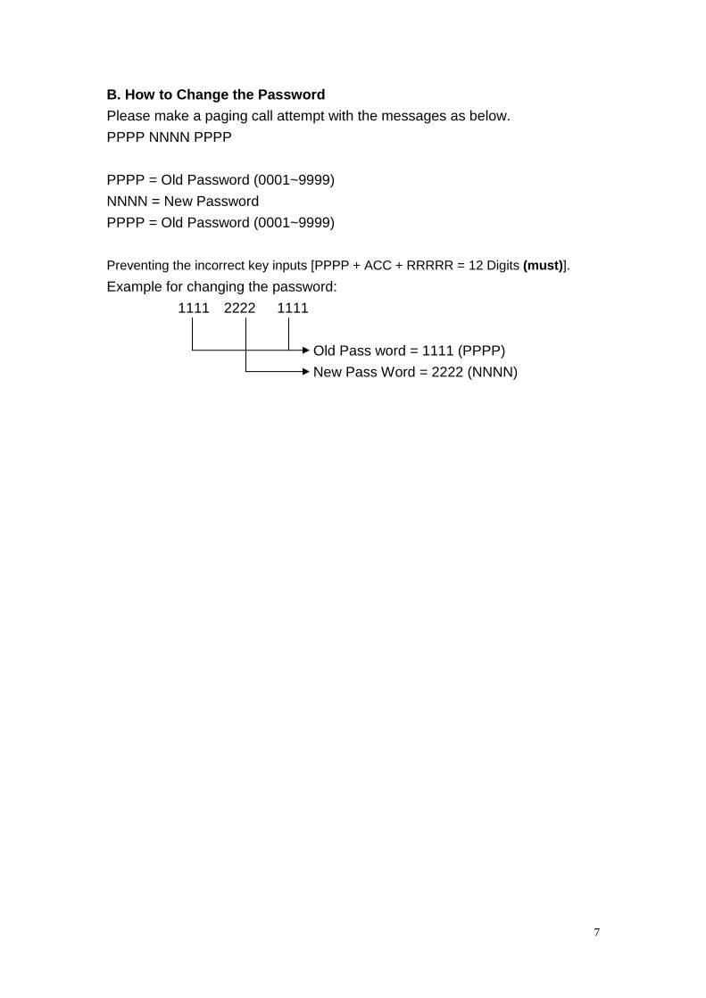
B. How to Change the Password
Please make a paging call attempt with the messages as below.
PPPP NNNN PPPP
PPPP = Old Password (0001~9999)
NNNN = New Password
PPPP = Old Password (0001~9999)
Preventing the incorrect key inputs [PPPP + ACC + RRRRR = 12 Digits (must)].
Example for changing the password:
1111 2222 1111
Old Pass word = 1111 (PPPP)
New Pass Word = 2222 (NNNN)

8
C.How to programming the Y1727RY2
1).Connected with DC plug and RS-232 plug into Y1727-Programmer
2). Into data wire to Y1727RY2 Set
3).Connected RS-232 cable to P/C or N/B
4). Install programming CD on your P/C or N/B
5) Click [Pager Module programming Kit-y1707V1] to set-up your Y1727RY2..

9
Programming with Y1727RY2 (Same As Y1707 A/P)
1. Frequency:
This set-up is used for the reference information only: It does not affect any
Technical features contained in the Y1727RY2 unit.
2. Y1727RY2 Address (Cap Code) Set-Up:
There are total 6 addresses in this unit with each address range from:
Addr 1: set from 0000008 to 2097151. And it must key in 0 digit if disable.
Addr 2: set from 0000008 to 2097151. And it must key in 0 digit if disable.
Addr 3: set from 0000008 to 2097151. And it must key in 0 digit if disable.
Addr 4: set from 0000008 to 2097151. And it must key in 0 digit if disable.
Addr 5: set from 0000008 to 2097151. And it must key in 0 digit if disable.
Addr 6: set from 0000008 to 2097151. And it must key in 0 digit if disable.
Be sure to enter the “0” digit if the “disable” feature is required. Please
Do not leave it blank. Since this will cause the unit malfunction.
3. Command Password Control Set-Up:
There are total in 4 digits’ numeric command password from 0000 to 9999.
And this programming and alternation can be set either by computer or
through the air paging messaging from the applied operator network.
4. Customer ID Set-Up:
Also, the customer ID contains 4 numeric digits from 0000 to 9999. And this
10
ID only can be set vis the PC computer from your local authorized dealer. The Air
paging messages can not have any changes of this set-up.
5. Re-Program ID Set-Up:
There are 5 digits re-program ID reserved for the authorized dealer to
alternate the unit address from the air paging. Please must make sure
These programmed digits before the air paging alternations.
6. At the Start of the Text:
This is to distinguish each receiving messages by adding the programmed
Characters at The start of the text.
7. At the End of The Text:
This is to distinguish each receiving messages by adding the programmed
Characters at the end of the text.
8. Power Saving Set-Up:
“Enable” stands for the power ON-Off-ON-Off. And the “disable” means
The power output always ON.
Remark: This feature is reserved for the PDA operation only.
9. Baud Rate Set-Up: 512/1200/2400 bps for Paging data speed.
10. Data Polarity Set-Up: Can be set by normal data or invert data polarity.
11. Message Type Set-Up:
For numeric (4 bit) or Alphanumeric (7 bit) or Auto (not active yet) set-up.
12. Password Change Over The Air Set-Up:
This feature is to allow users changing their current password through
The service provider’s air messages paging.
13. Address (Cap Code) Alternation Over The Air Set-Up:
This feature is to alternate the Y1727RY2 unit’s 7 address digits changes through
The service provider’s air messages paging.
14. Memory Select Set-Up:
If set at the “power off all reset”, the relay’s received commands will all be
cleared out once the power off and on again. And the “keep last command
status” is to recall the last commands after the power on again.
15. SAVE Function: To save the programmed data into the computer.
16. WRITE Function: To write the programmed data into the Y1727RY2.
17. READ Function: Read the programmed data out from Y1727RY2 unit.
18. EXIT Function: To exit this programming software.
19. Command Buffer Set-Up: For engineer use only.
20. Com Port Pool:
The Y1727RY2’s receiving data can be monitored in this screen. And
The other way to view these data is to activate the Hyper terminal screen
under the MS windows operational software.

11
Part No. and location on PCB.
Y1727RY2 V1.3
item no. Part list BOM688113201457
Part No. Description Remark
1 U1 GS7812D Regulator for dc 12V
2 U2 HT-7530-1 Regulator for dc 3V
3 U3 PIC16F76-04/SO1707v1.3 Micro controller unit (MCU)
4 U4 NC not used for v1.3 only
5 U5 93C66 EE Prom
6 U6 CS9522P SOP POCSAG Decoder unit (PDU)
7 Q1 2N3904 NPN Transistor
8 Q2 2N3904 NPN Transistor
9 D1 1N4403 3A Diode for DC source protect
10 D2 LED Red color Power on indicate
11 D3 LED Green color RX link indicate

12
12 D4 LED Red color Relay 1 active indicate
13 D5 LED Red color Relay 2 active indicate
14 R1 10M ohm 0603 SMD
15 R2 10M ohm 0603 SMD
16 R3 10K ohm 0603 SMD
17 R4 10K ohm 0603 SMD
18 R5 2.2 ohm 0603 SMD
19 R6 2.2 ohm 0603 SMD
20 R7 1K ohm 0603 SMD
21 R8 430 ohm 0603 SMD
22 R9 430 ohm 0603 SMD
23 R10 430 ohm 0603 SMD
24 R11 1K ohm 0603 SMD
25 R12 1K ohm 0603 SMD
26 *R 4.7K ohm 0603 SMD
27 C1 10u/16V E/C 6x5mm SMD
28 C2 10u/16V E/C 6x5mm SMD
29 C3 102 Y5V CM/C 0603
30 C4 16P NP0 CM/C 0603
31 C5 16P NP0 CM/C 0603
32 C6 102 Y5V CM/C 0603
33 C7 102 Y5V CM/C 0603
34 C8 105 Y5V CM/C 0805
35 C9 102 Y5V CM/C 0603
36 C10 102 Y5V CM/C 0603
37 *C 105 Y5V CM/C 0603
38 X1 4.0MHz Resonator
39 Y1 Quartz crystal 76.8KHz 3x9mm
40 J1 DC jack DC-022 DC power jack
41 J2 2.54mm x4HU for TTL operation & programming
42 J3 1.27mm x7 x2 for Receiver module RMB-100
43 J4 1.27mm x5 x1 for Receiver module RMB-500
13
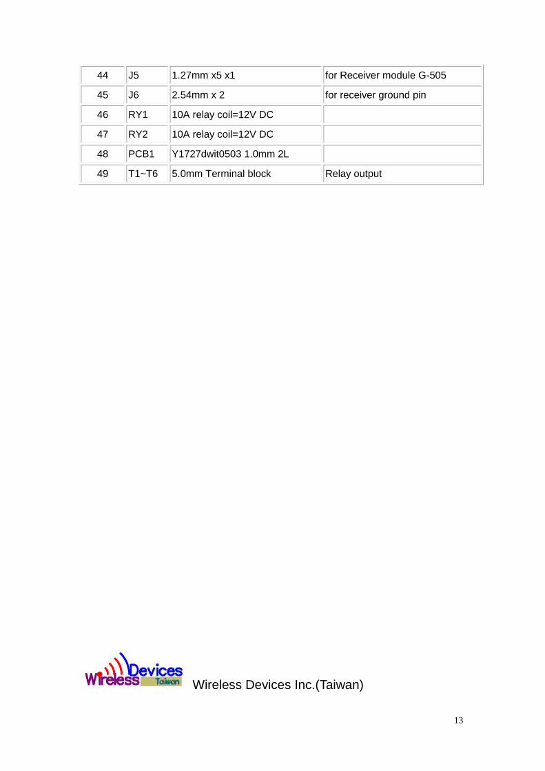
44 J5 1.27mm x5 x1 for Receiver module G-505
45 J6 2.54mm x 2 for receiver ground pin
46 RY1 10A relay coil=12V DC
47 RY2 10A relay coil=12V DC
48 PCB1 Y1727dwit0503 1.0mm 2L
49 T1~T6 5.0mm Terminal block Relay output
Wireless Devices Inc.(Taiwan)