Embed Size (px)
Citation preview
Joachim Rodrigues, EIT, LTH, Introduction to Structured VLSI Design [email protected] VHDL I
Introduction to Structured VLSI Design‐ VHDL I
Joachim Rodrigues
Joachim Rodrigues, EIT, LTH, Introduction to Structured VLSI Design [email protected] VHDL I
Two HDLs used today
–VHDL and Verilog
– Syntax and ``appearance'' of the two languages are very different
–Capabilities and scopes are quite similar
–Both are industrial standards and are supported by most software tools
Joachim Rodrigues, EIT, LTH, Introduction to Structured VLSI Design [email protected] VHDL I
VHDL
Very High Speed Integrated Circuit (VHSIC)
Hardware
Description
Language
A Technology Independent, Standard Hardware description Language (HDL), used for digital system modeling, simulation, and synthesis
Joachim Rodrigues, EIT, LTH, Introduction to Structured VLSI Design [email protected] VHDL I
Why VHDL?
There are several hardware description languages available; VHDL (Europe), Verilog (USA), and System C are the most common.
Advantages of VHDL• IEEE standard.• Supported by all CAD Tools.• Technology independent.• Common – Specially in Europe. • Flexible – Delay modeling, Matrices, etc. • Supports easy modeling of various abstraction levels.
Joachim Rodrigues, EIT, LTH, Introduction to Structured VLSI Design [email protected] VHDL I
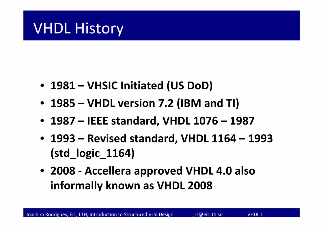
VHDL History
• 1981 – VHSIC Initiated (US DoD)
• 1985 – VHDL version 7.2 (IBM and TI)
• 1987 – IEEE standard, VHDL 1076 – 1987
• 1993 – Revised standard, VHDL 1164 – 1993 (std_logic_1164)
• 2008 ‐ Accellera approved VHDL 4.0 also informally known as VHDL 2008
Joachim Rodrigues, EIT, LTH, Introduction to Structured VLSI Design [email protected] VHDL I
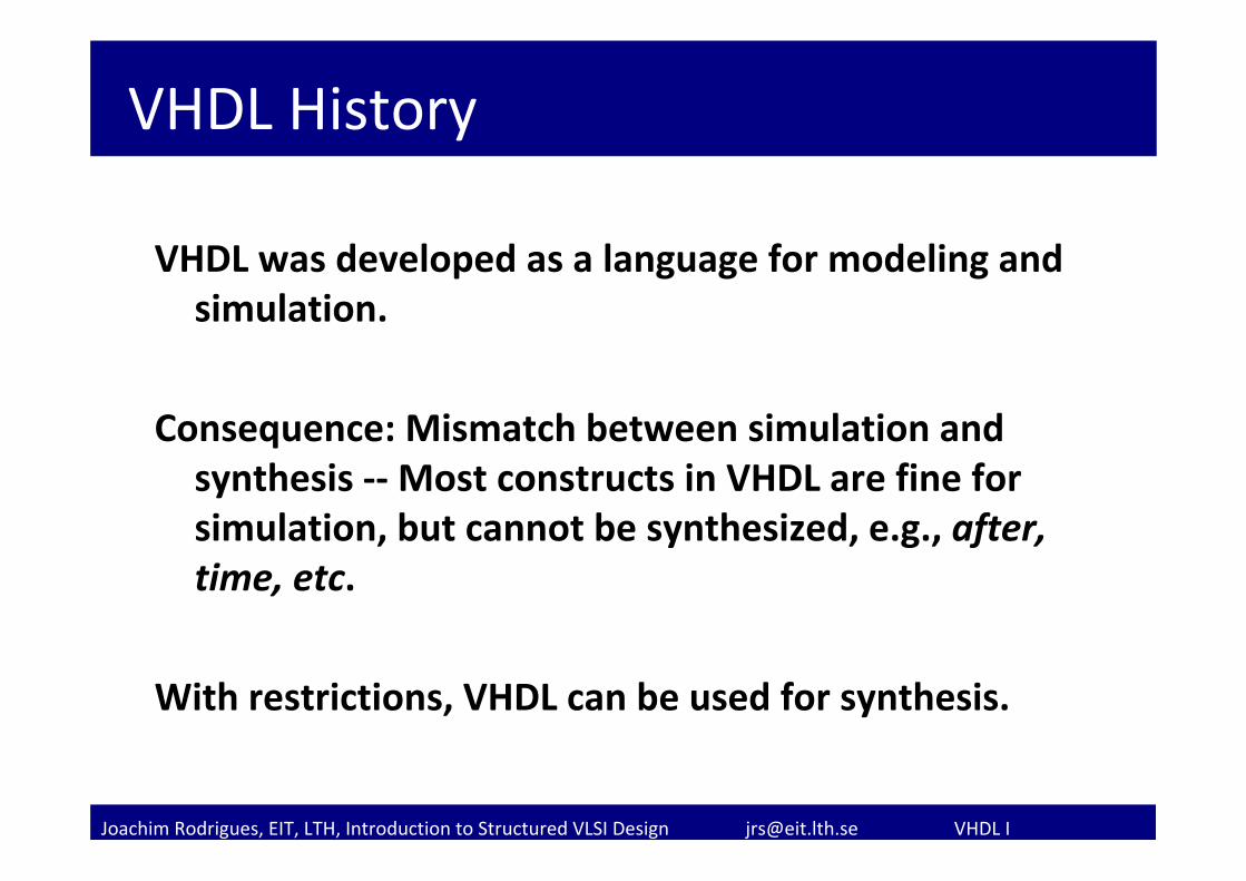
VHDL History
VHDL was developed as a language for modeling and simulation.
Consequence: Mismatch between simulation and synthesis ‐‐Most constructs in VHDL are fine for simulation, but cannot be synthesized, e.g., after, time, etc.
With restrictions, VHDL can be used for synthesis.
Joachim Rodrigues, EIT, LTH, Introduction to Structured VLSI Design [email protected] VHDL I
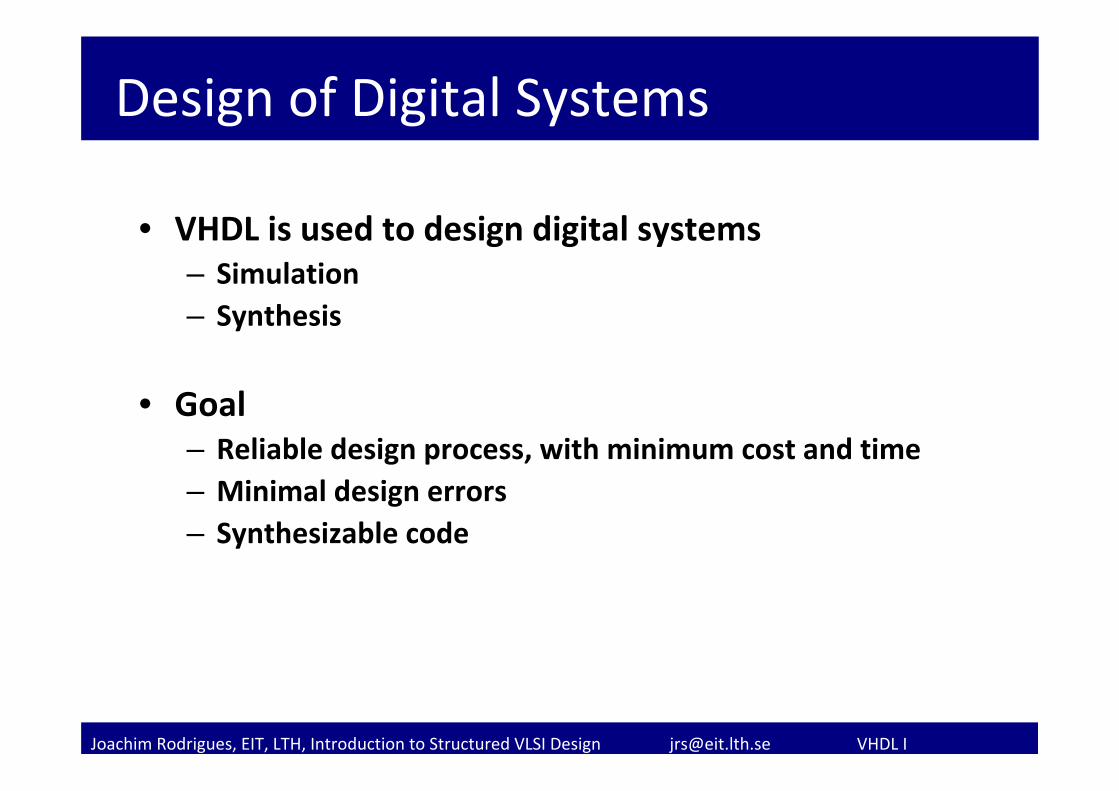
Design of Digital Systems
• VHDL is used to design digital systems– Simulation– Synthesis
• Goal– Reliable design process, with minimum cost and time– Minimal design errors– Synthesizable code
Joachim Rodrigues, EIT, LTH, Introduction to Structured VLSI Design [email protected] VHDL I
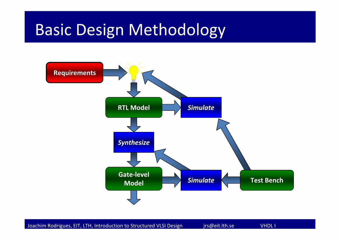
Basic Design Methodology
Requirements
SimulateRTL Model
Gate‐levelModel
Synthesize
Simulate Test Bench
Simulate
Synthesize
Simulate
Joachim Rodrigues, EIT, LTH, Introduction to Structured VLSI Design [email protected] VHDL I
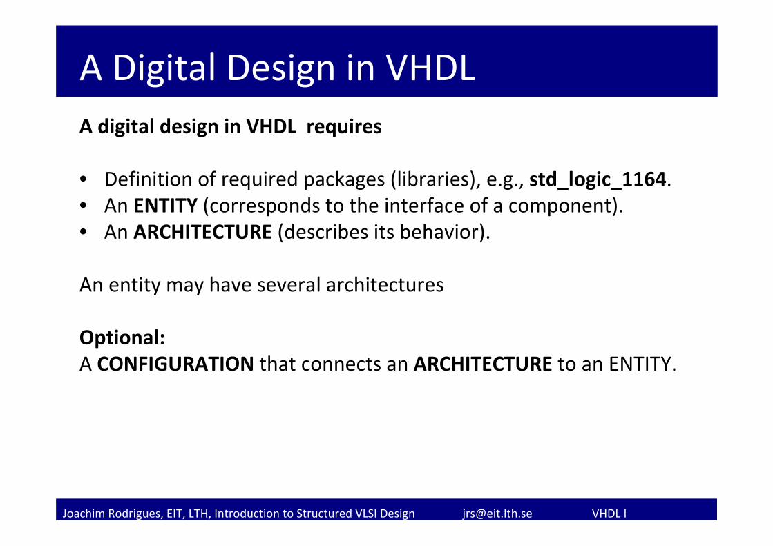
A Digital Design in VHDLA digital design in VHDL requires
• Definition of required packages (libraries), e.g., std_logic_1164.• An ENTITY (corresponds to the interface of a component).• An ARCHITECTURE (describes its behavior).
An entity may have several architectures
Optional:A CONFIGURATION that connects an ARCHITECTURE to an ENTITY.
Joachim Rodrigues, EIT, LTH, Introduction to Structured VLSI Design [email protected] VHDL I
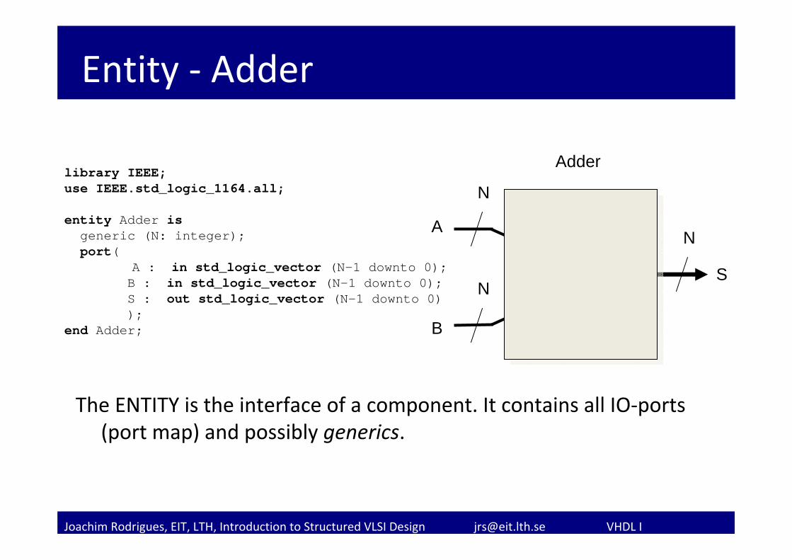
Entity ‐ Adder
The ENTITY is the interface of a component. It contains all IO‐ports (port map) and possibly generics.
library IEEE;use IEEE.std_logic_1164.all;
entity Adder isgeneric (N: integer);port(
A : in std_logic_vector (N-1 downto 0);B : in std_logic_vector (N-1 downto 0);S : out std_logic_vector (N-1 downto 0));
end Adder; B
S
A
+
Adder
N
N
N
Joachim Rodrigues, EIT, LTH, Introduction to Structured VLSI Design [email protected] VHDL I
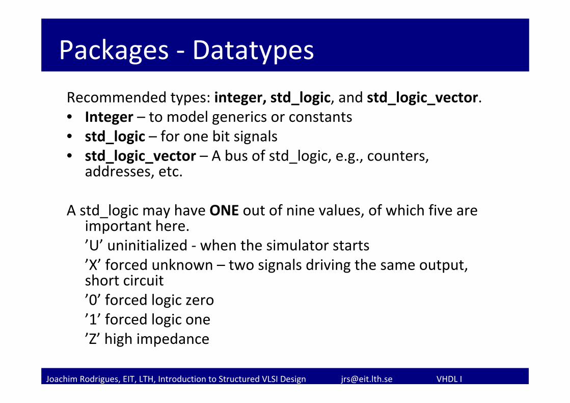
Packages ‐ Datatypes
Recommended types: integer, std_logic, and std_logic_vector.• Integer – to model generics or constants• std_logic – for one bit signals• std_logic_vector – A bus of std_logic, e.g., counters,
addresses, etc.
A std_logic may have ONE out of nine values, of which five are important here.’U’ uninitialized ‐ when the simulator starts’X’ forced unknown – two signals driving the same output, short circuit’0’ forced logic zero’1’ forced logic one’Z’ high impedance
Joachim Rodrigues, EIT, LTH, Introduction to Structured VLSI Design [email protected] VHDL I
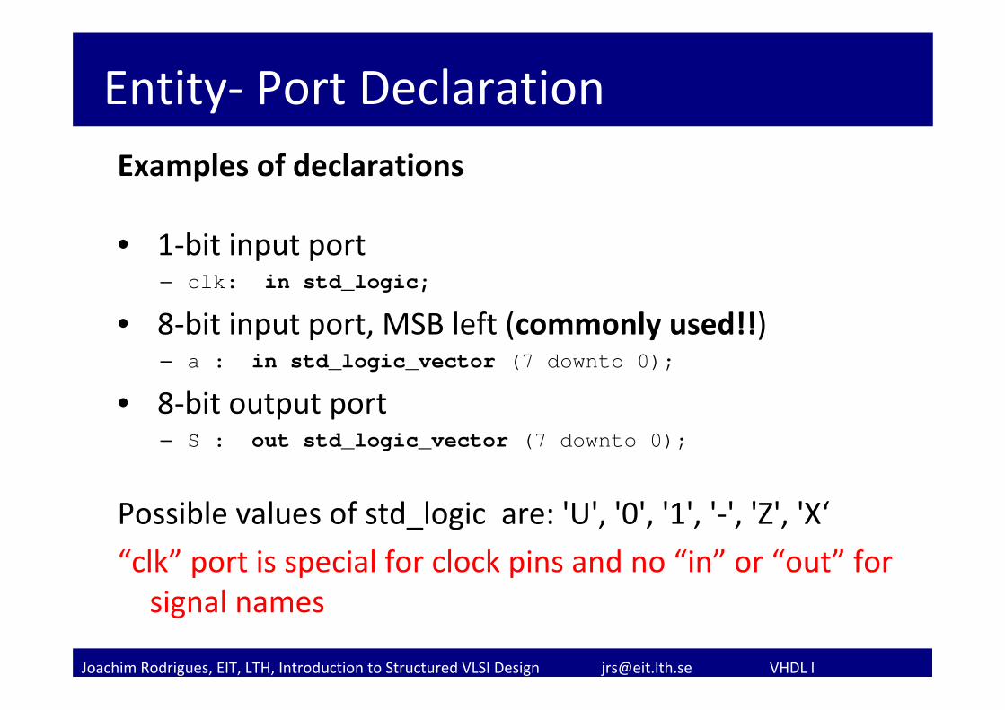
Entity‐ Port DeclarationExamples of declarations
• 1‐bit input port– clk: in std_logic;
• 8‐bit input port, MSB left (commonly used!!)– a : in std_logic_vector (7 downto 0);
• 8‐bit output port– S : out std_logic_vector (7 downto 0);
Possible values of std_logic are: 'U', '0', '1', '‐', 'Z', 'X‘
“clk” port is special for clock pins and no “in” or “out” for signal names
Joachim Rodrigues, EIT, LTH, Introduction to Structured VLSI Design [email protected] VHDL I
Entity ‐ Generics
Used to pass certain properties into a design to make it more general. Typically:
• Bus widths
• Delays
The value can be set in the entity declaration (default value), component declaration, or component instantiation.
Joachim Rodrigues, EIT, LTH, Introduction to Structured VLSI Design [email protected] VHDL I
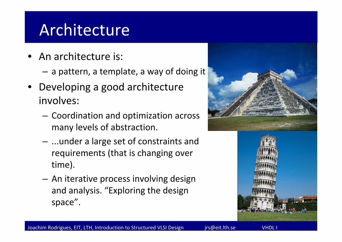
Architecture• An architecture is:
– a pattern, a template, a way of doing it
• Developing a good architecture involves:– Coordination and optimization across many levels of abstraction.
– ...under a large set of constraints and requirements (that is changing over time).
– An iterative process involving design and analysis. “Exploring the design space”.
Joachim Rodrigues, EIT, LTH, Introduction to Structured VLSI Design [email protected] VHDL I
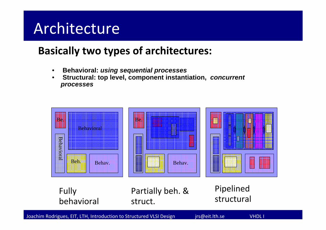
ArchitectureBasically two types of architectures:
• Behavioral: using sequential processes• Structural: top level, component instantiation, concurrent
processes
Behavioral
Behav.
Behavioral
Beh.
Be.
Behav.
Be.
Fully behavioral
Partially beh. & struct.
Pipelined structural
Joachim Rodrigues, EIT, LTH, Introduction to Structured VLSI Design [email protected] VHDL I
B
A
Adder
N
N
N
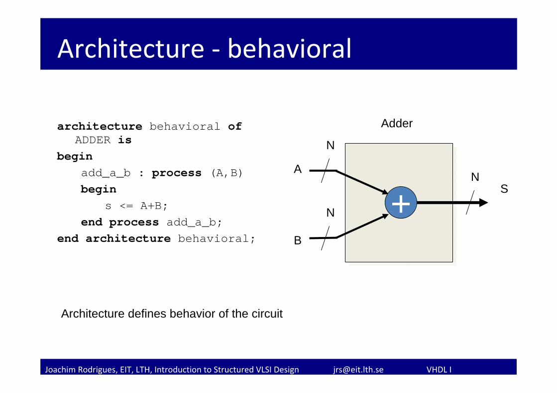
Architecture ‐ behavioral
architecture behavioral ofADDER is
beginadd_a_b : process (A,B) begin
s <= A+B;end process add_a_b;
end architecture behavioral;
S+
Architecture defines behavior of the circuit
Joachim Rodrigues, EIT, LTH, Introduction to Structured VLSI Design [email protected] VHDL I
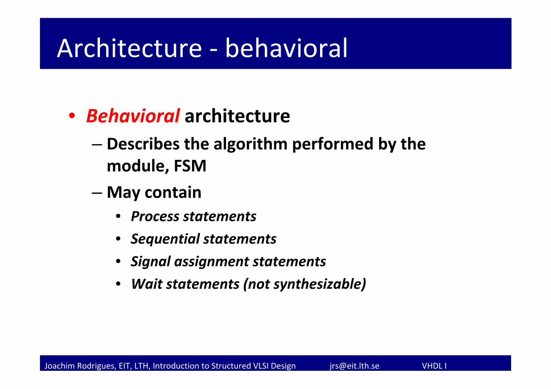
Architecture ‐ behavioral
• Behavioral architecture– Describes the algorithm performed by the module, FSM
– May contain• Process statements
• Sequential statements
• Signal assignment statements
• Wait statements (not synthesizable)
Joachim Rodrigues, EIT, LTH, Introduction to Structured VLSI Design [email protected] VHDL I
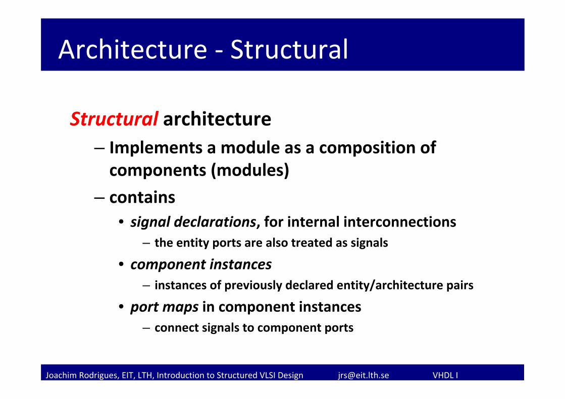
Architecture ‐ Structural
Structural architecture– Implements a module as a composition of components (modules)
– contains• signal declarations, for internal interconnections
– the entity ports are also treated as signals
• component instances– instances of previously declared entity/architecture pairs
• port maps in component instances– connect signals to component ports
Joachim Rodrigues, EIT, LTH, Introduction to Structured VLSI Design [email protected] VHDL I
Structural description
• In structural view, a circuit is constructed by smaller parts.
• Structural description specifies the types of parts and connections.
• Essentially a textual description of a schematic• Done by using “component” in VHDL
– First declared (make known) – Then instantiated (used)
Joachim Rodrigues, EIT, LTH, Introduction to Structured VLSI Design [email protected] VHDL I
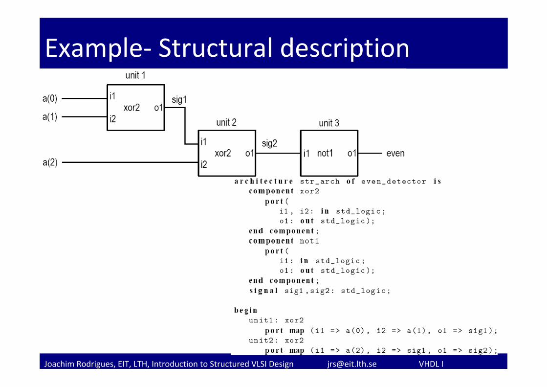
Example‐ Structural description
Joachim Rodrigues, EIT, LTH, Introduction to Structured VLSI Design [email protected] VHDL I
Mixing Behavioral and Structural
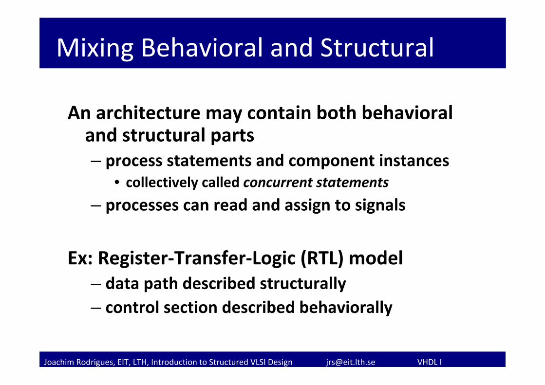
An architecture may contain both behavioral and structural parts– process statements and component instances
• collectively called concurrent statements
– processes can read and assign to signals
Ex: Register‐Transfer‐Logic (RTL) model– data path described structurally– control section described behaviorally
Joachim Rodrigues, EIT, LTH, Introduction to Structured VLSI Design [email protected] VHDL I
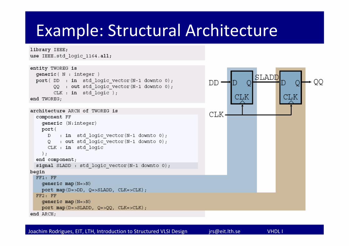
Example: Structural Architecture
Joachim Rodrigues, EIT, LTH, Introduction to Structured VLSI Design [email protected] VHDL I
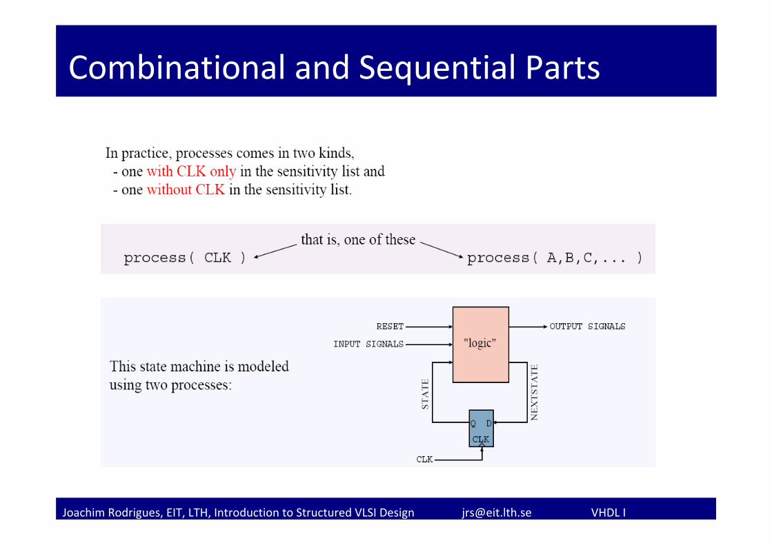
Combinational and Sequential Parts
Joachim Rodrigues, EIT, LTH, Introduction to Structured VLSI Design [email protected] VHDL I
Concurrent Statements and Processes
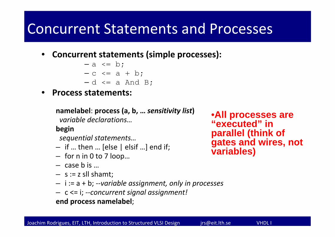
• Concurrent statements (simple processes):– a <= b;– c <= a + b;– d <= a And B;
• Process statements:
namelabel: process (a, b, … sensitivity list)variable declarations…beginsequential statements…
– if … then … [else | elsif …] end if;– for n in 0 to 7 loop…– case b is …– s := z sll shamt;– i := a + b; ‐‐variable assignment, only in processes– c <= i; ‐‐concurrent signal assignment!end process namelabel;
•All processes are “executed” in parallel (think of gates and wires, not variables)
Joachim Rodrigues, EIT, LTH, Introduction to Structured VLSI Design [email protected] VHDL I
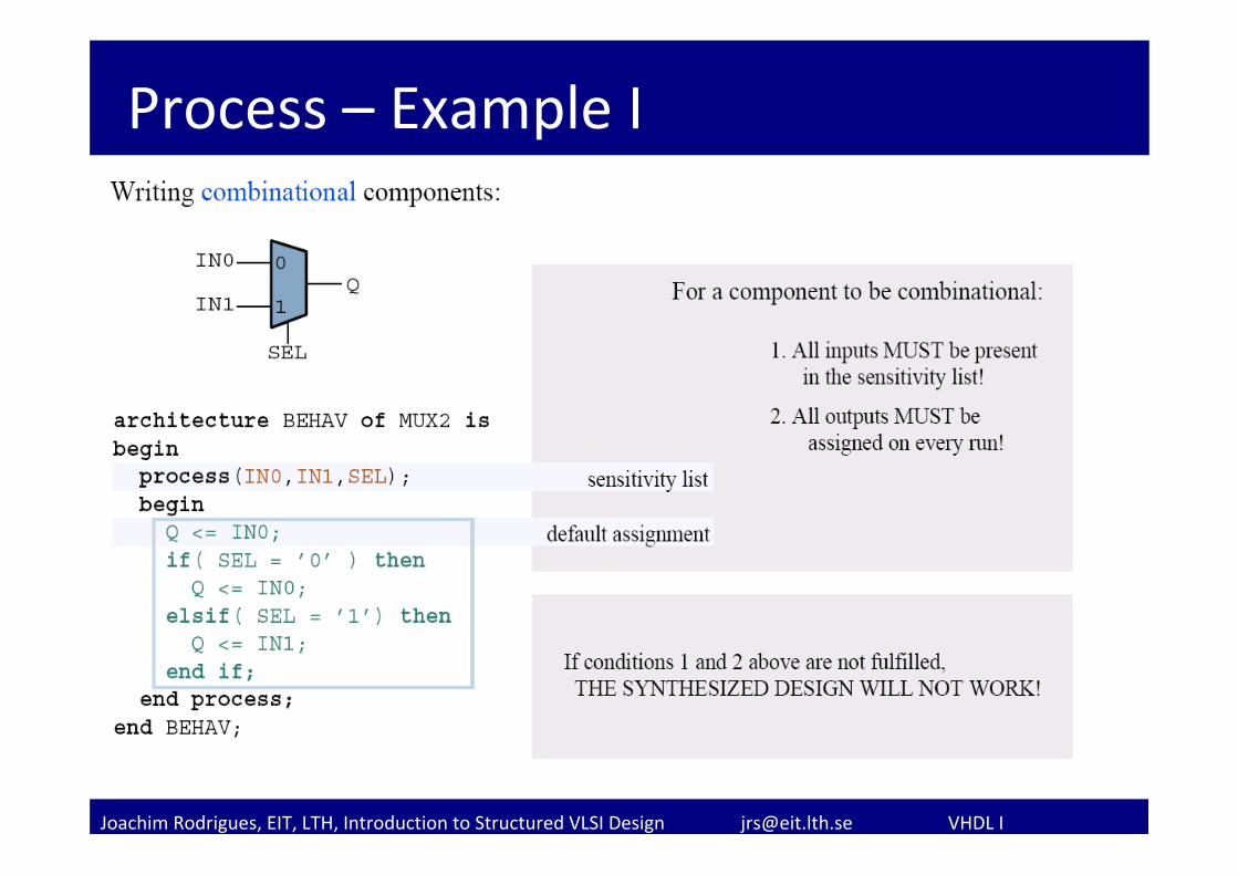
Process – Example I
Joachim Rodrigues, EIT, LTH, Introduction to Structured VLSI Design [email protected] VHDL I
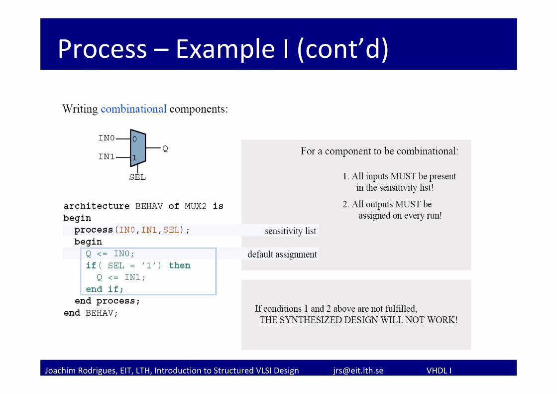
Process – Example I (cont’d)
Joachim Rodrigues, EIT, LTH, Introduction to Structured VLSI Design [email protected] VHDL I
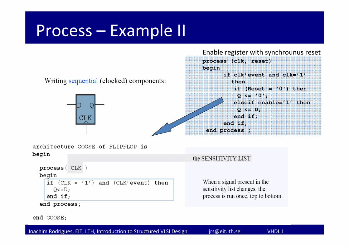
Process – Example II
process (clk, reset)begin
if clk’event and clk=’1’thenif (Reset = '0') thenQ <= '0';elseif enable=’1’ thenQ <= D;end if;
end if;end process ;
Enable register with synchrounus reset
Joachim Rodrigues, EIT, LTH, Introduction to Structured VLSI Design [email protected] VHDL I
Case command
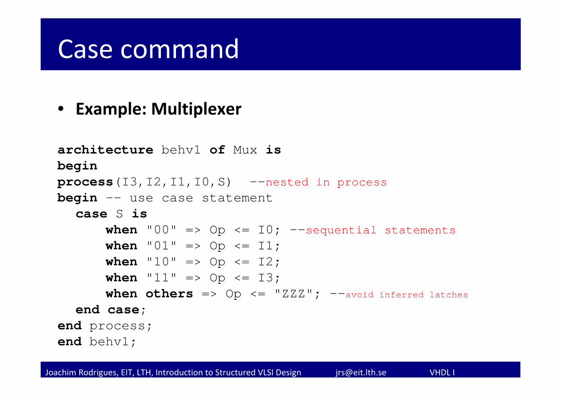
• Example: Multiplexer
architecture behv1 of Mux isbeginprocess(I3,I2,I1,I0,S) --nested in processbegin -- use case statement
case S iswhen "00" => Op <= I0; --sequential statementswhen "01" => Op <= I1; when "10" => Op <= I2; when "11" => Op <= I3; when others => Op <= "ZZZ"; --avoid inferred latches
end case; end process; end behv1;
Joachim Rodrigues, EIT, LTH, Introduction to Structured VLSI Design [email protected] VHDL I
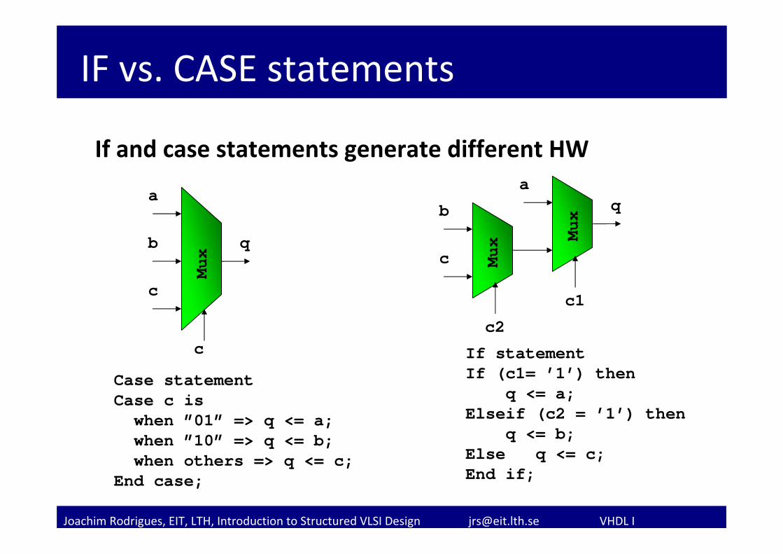
IF vs. CASE statements
If and case statements generate different HW
If statementIf (c1= ’1’) then
q <= a;Elseif (c2 = ’1’) then
q <= b;Else q <= c;End if;
b
Mux
q
Mux
c
a
c2
c1
Case statementCase c iswhen ”01” => q <= a;when ”10” => q <= b;when others => q <= c;
End case;
b
Mux
q
c
c
a
Joachim Rodrigues, EIT, LTH, Introduction to Structured VLSI Design [email protected] VHDL I
Finite State Machines
Why FSMs?– Models different behavoiur at different times (states)
A state machine requires:– An initial state (Reset)– Transitions with stable states– Default values (Case statement)
Realizes:– Datapath– Controller– Datapath+Controller
Joachim Rodrigues, EIT, LTH, Introduction to Structured VLSI Design [email protected] VHDL I
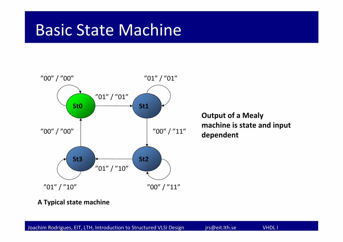
Basic State Machine
St1St0”01” / ”01”
”00” / ”11”
”01” / ”01””00” / ”00”
”00” / ”11”
”00” / ”00”
”01” / ”10”
”01” / ”10”
A Typical state machine
St3 St2
Output of a Mealy machine is state and input dependent
Joachim Rodrigues, EIT, LTH, Introduction to Structured VLSI Design [email protected] VHDL I
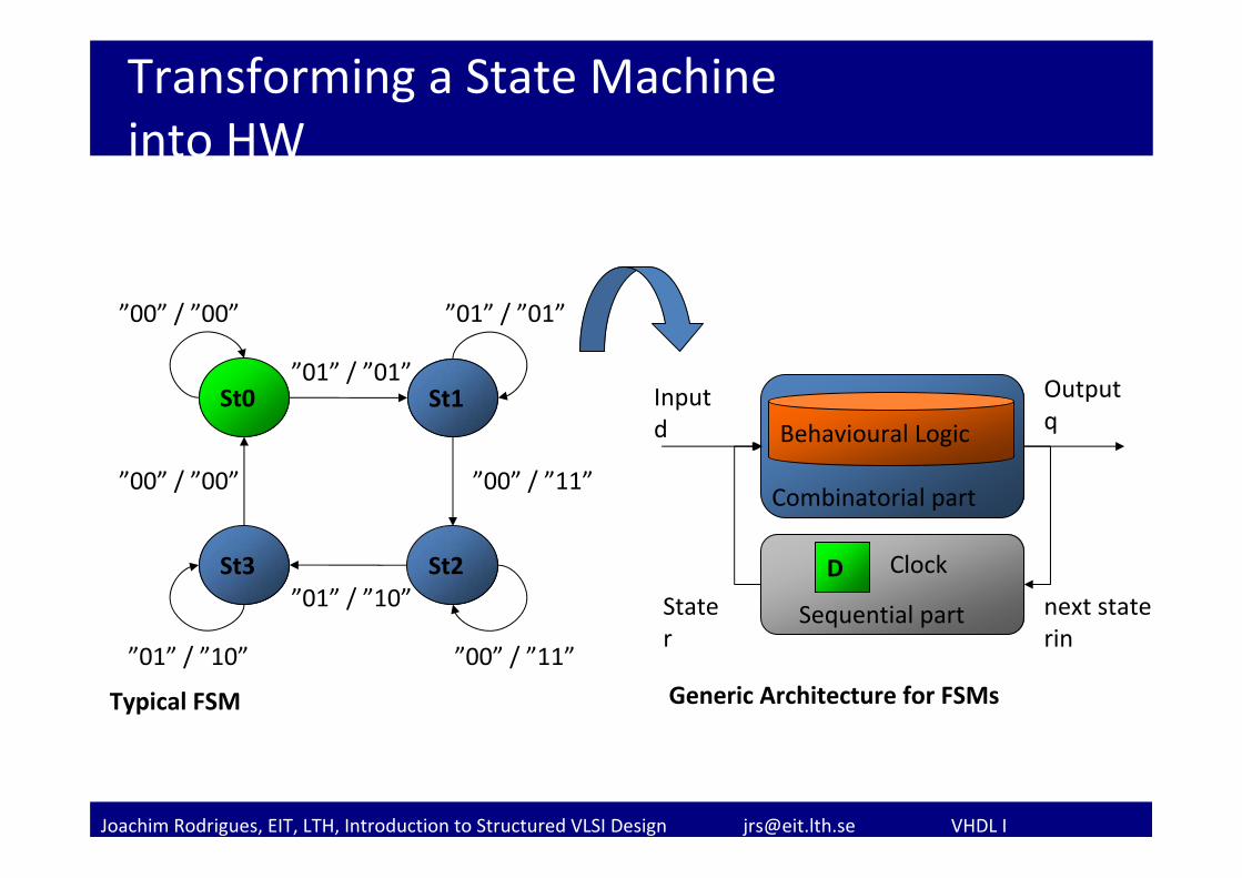
Transforming a State Machine into HW
Behavioural Logic
D
Combinatorial part
Sequential part
Outputq
Inputd
Stater
Clock
next staterin
Generic Architecture for FSMs
St1St0”01” / ”01”
”00” / ”11”
”01” / ”01””00” / ”00”
”00” / ”11”
”00” / ”00”
”01” / ”10”
”01” / ”10”
Typical FSM
St3 St2
Joachim Rodrigues, EIT, LTH, Introduction to Structured VLSI Design [email protected] VHDL I
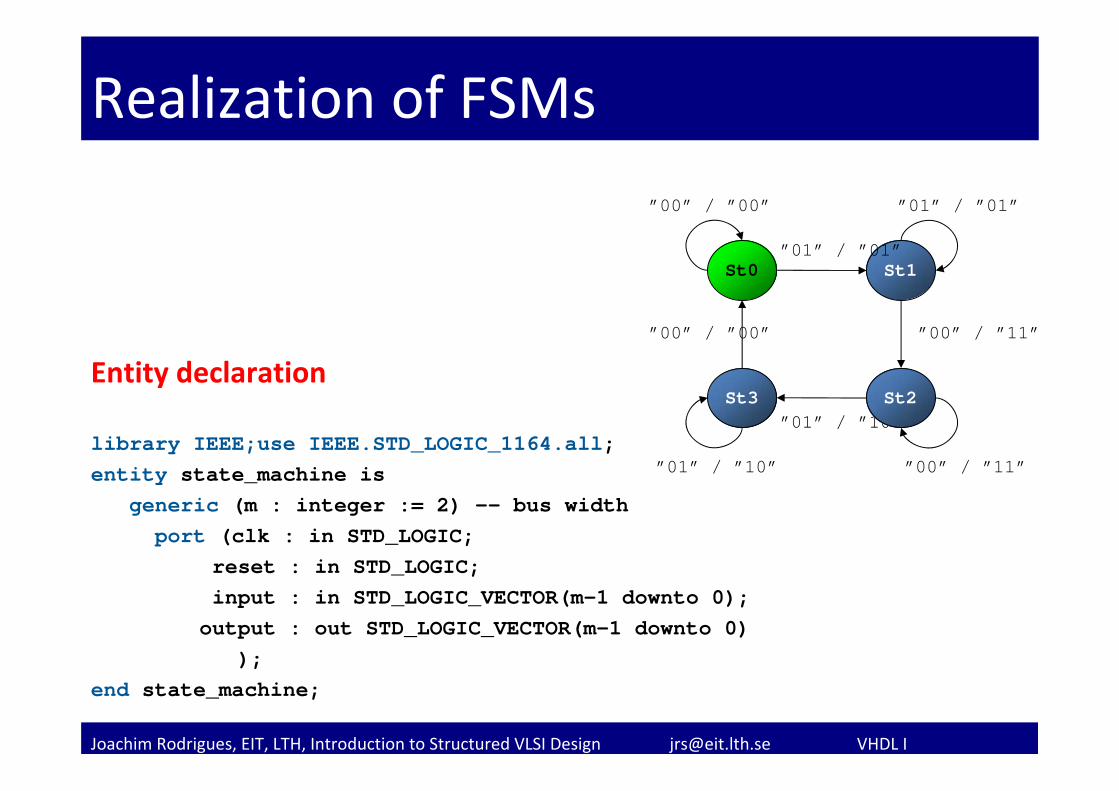
Realization of FSMs
Entity declaration
library IEEE;use IEEE.STD_LOGIC_1164.all;entity state_machine is
generic (m : integer := 2) -- bus width port (clk : in STD_LOGIC;
reset : in STD_LOGIC;input : in STD_LOGIC_VECTOR(m-1 downto 0);output : out STD_LOGIC_VECTOR(m-1 downto 0)
); end state_machine;
St1St0”01” / ”01”
”00” / ”11”
”01” / ”01””00” / ”00”
”00” / ”11”
”00” / ”00”
”01” / ”10”
”01” / ”10”
St3 St2
Joachim Rodrigues, EIT, LTH, Introduction to Structured VLSI Design [email protected] VHDL I
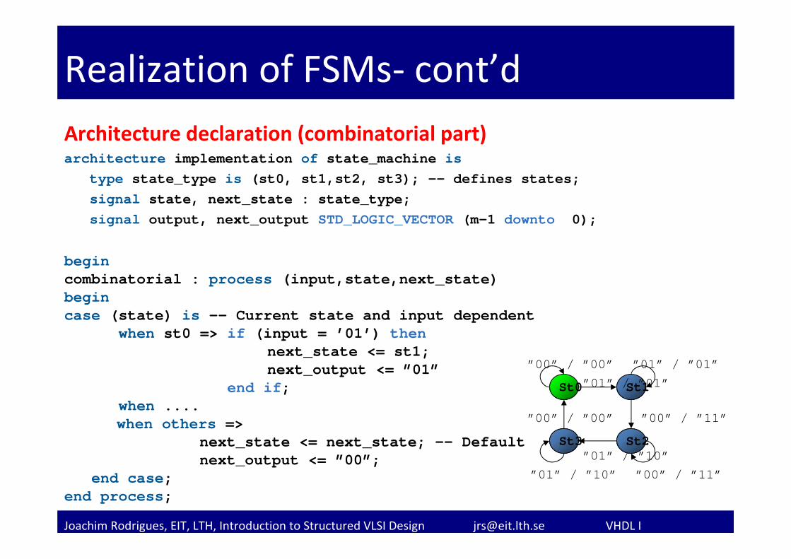
Realization of FSMs‐ cont’dArchitecture declaration (combinatorial part)architecture implementation of state_machine is
type state_type is (st0, st1,st2, st3); -- defines states;signal state, next_state : state_type;signal output, next_output STD_LOGIC_VECTOR (m-1 downto 0);
begin combinatorial : process (input,state,next_state) begincase (state) is -- Current state and input dependent
when st0 => if (input = ’01’) thennext_state <= st1;next_output <= ”01”
end if;when ....when others =>
next_state <= next_state; -- Default next_output <= ”00”;
end case;end process;
St1St0”01” / ”01”
”00” / ”11”
”01” / ”01””00” / ”00”
”00” / ”11”
”00” / ”00”
”01” / ”10””01” / ”10”
St3 St2
Joachim Rodrigues, EIT, LTH, Introduction to Structured VLSI Design [email protected] VHDL I
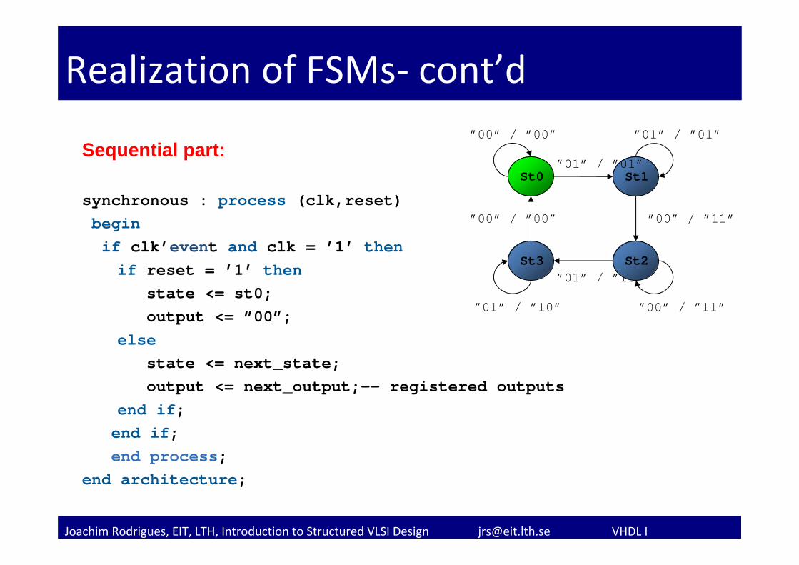
Realization of FSMs‐ cont’d
Sequential part:
synchronous : process (clk,reset)beginif clk’event and clk = ’1’ thenif reset = ’1’ then
state <= st0;output <= ”00”;
elsestate <= next_state;output <= next_output;-- registered outputs
end if;end if;end process;
end architecture;
St1St0”01” / ”01”
”00” / ”11”
”01” / ”01””00” / ”00”
”00” / ”11”
”00” / ”00”
”01” / ”10”
”01” / ”10”
St3 St2
Joachim Rodrigues, EIT, LTH, Introduction to Structured VLSI Design [email protected] VHDL I
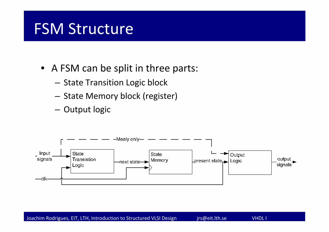
FSM Structure
• A FSM can be split in three parts:– State Transition Logic block
– State Memory block (register)
– Output logic
Joachim Rodrigues, EIT, LTH, Introduction to Structured VLSI Design [email protected] VHDL I
Summary
The knowledge you have gained today is sufficient to implement a simple combinational or structural architecture.
Joachim Rodrigues, EIT, LTH, Introduction to Structured VLSI Design [email protected] VHDL I
What’s next?
• Continue sequence detector
• Find a lab buddy
• 2nd VHDL presentation Monday next week
First Deadline: Preparation of sequence detector Tuesday 7th