Embed Size (px)
Citation preview

Evolution-30Intracavity-Doubled, Diode-Pumped Nd:YLF Laser
User’s Manual
The Solid-State Laser Company
1335 Terra Bella AvenueMountain View, CA 94043
Part Number 0000-298A, Rev. BDecember 2002


iii
Preface
This manual provides information regarding the operation and maintenanceof the Evolution-30 Laser. Spectra-Physics will send a representative toinstall the Evolution-30—call us for details. The performance of the Evolu-tion-30 is not guaranteed unless it is installed by an authorized representa-tive of Spectra-Physics.
The “Introduction” contains a brief description of the Evolution-30 lasersystem and the accessories provided with it.
Following that section is an important chapter on safety. The Evolution-30is a Class IV laser and, as such, emits laser radiation which can perma-nently damage eyes and skin. This section contains information about thesehazards and offers suggestions on how to safeguard against them. To mini-mize the risk of injury or expensive repairs, be sure to read this chapter—then carefully follow these instructions.
“Laser Overview” contains a short section on laser theory regarding theNd:YLF crystal and second harmonic generation used in the Evolution-30.It is followed by a more detailed description of the Evolution-30 laser sys-tem and concludes with system specifications and outline drawings.
The next few chapters describe the Evolution-30 controls, then guide youthrough its installation and operation. The last part of the manual coversservice and includes a replacement parts list and a list of world-wide Spectra-Physics service centers you can call if you need help.
“Service and Repair” is intended to help you guide your Spectra-Physicsfield service engineer to the source of any problems. Do not attempt repairsyourself while the unit is still under warranty; instead, report all problemsto Spectra-Physics for warranty repair.
This product has been tested and found to conform to “Directive 89/336/EEC for Electromagnetic Compatibility.” Class A compliance was demon-strated for “EN 50081-2:1993 Emissions” and “EN 50082-1:1992 Immu-nity” as listed in the official Journal of the European Communities. It alsomeets the intent of “Directive 73/23/EEC for Low Voltage.” Class A com-pliance was demonstrated for “EN 61010-1:1993 Safety Requirements forElectrical Equipment for Measurement, Control and Laboratory use” and“EN 60825-1:1992 Radiation Safety for Laser Products.” Refer to the “CEDeclaration of Conformity” in Chapter 2: Laser Safety.
This product conforms to the requirements of 21 CFR 1040.10 CDRH andis compliant to Underwriters Laboratory UL1950 and is listed as ULR forrecognized components. This equipment has been designed and tested tocomply with the limits for a Class A digital device pursuant to Part 15 ofthe FCC Rules.
Evolution-30 Intracavity-Doubled, Diode-Pumped Nd:YLF Laser
iv
Every effort has been made to ensure that the information in this manual isaccurate. All information in this document is subject to change withoutnotice. Spectra-Physics makes no representation or warranty, either expressor implied, with respect to this document. In no event will Spectra-Physicsbe liable for any direct, indirect, special, incidental or consequential dam-ages resulting from any defects in this documentation.
Should you experience any problems with any equipment purchased fromSpectra-Physics, or you are in need of technical information or support,please contact Spectra-Physics as described in Chapter 7 “Troubleshootingand Customer Service.”
Except as permitted under the United States Copyright Act of 1976, no partof this publication may be reproduced or distributed in any form or by anymeans, or stored in a data base or retrieval system, without the prior writtenpermission of Spectra-Physics. Under the law, copying includes translationinto another language.
Finally, if you encounter any difficulty with the content or style of thismanual, please let us know. The last page is a form to aid in bringing suchproblems to our attention.
Thank you for your purchase of Spectra-Physics instruments.

v
Environmental Specifications
Refer to Chapter 4, “System Installation,” for the dimensions of the majorEvolution-30 system components, and for information regarding correctplacement and spacing requirements.
CE Electrical Equipment Requirements
For information regarding the equipment needed to provide the electricalservice, please refer to specification EN-309, “Plug, Outlet and SocketCouplers for Industrial Uses,” listed in the official Journal of the EuropeanCommunities.
Environmental Specifications
The environmental conditions under which the laser system will functionare listed below:
Indoor use
Altitude: up to 2000 mTemperatures: 10° C to 40° CMaximum relative humidity: 80% non-condensing for temperatures
up to 31° C.Mains supply voltage: do not exceed ±10% of the nominal voltageInsulation category: IIPollution degree: 2
FCC Regulations
This equipment has been designed and tested to comply with the limits fora Class A digital device pursuant to Part 15 of the FCC Rules. These limitsare designed to provide reasonable protection against harmful interferencewhen the equipment is operated in a commercial environment. This equip-ment generates, uses and can radiate radio frequency energy and, if notinstalled and used in accordance with the instruction manual, may causeharmful interference to radio communications. Operation of this equipmentin a residential area is likely to cause harmful interference in which casethe user will be required to correct the interference at his own expense.
Modifications to the laser system not expressly approved by Spectra-Physicscould void your right to operate the equipment.


vii
Table of Contents
Preface . . . . . . . . . . . . . . . . . . . . . . . . . . . . . . . . . . . . . . . . . . . . . . . . . . . . . . . . . . . . . . iii
Environmental Specifications . . . . . . . . . . . . . . . . . . . . . . . . . . . . . . . . . . . . . . . . . . . vCE Electrical Equipment Requirements . . . . . . . . . . . . . . . . . . . . . . . . . . . . . . . . . . . . . . . . . . . . . . . . vEnvironmental Specifications . . . . . . . . . . . . . . . . . . . . . . . . . . . . . . . . . . . . . . . . . . . . . . . . . . . . . . . . vFCC Regulations . . . . . . . . . . . . . . . . . . . . . . . . . . . . . . . . . . . . . . . . . . . . . . . . . . . . . . . . . . . . . . . . . v
Warning Conventions . . . . . . . . . . . . . . . . . . . . . . . . . . . . . . . . . . . . . . . . . . . . . . . . . . xi
Standard Units . . . . . . . . . . . . . . . . . . . . . . . . . . . . . . . . . . . . . . . . . . . . . . . . . . . . . . . . xiii
Abbreviations. . . . . . . . . . . . . . . . . . . . . . . . . . . . . . . . . . . . . . . . . . . . . . . . . . . . . . . . . xv
Unpacking and Inspection . . . . . . . . . . . . . . . . . . . . . . . . . . . . . . . . . . . . . . . . . . . . . . xviiUnpacking Your Laser . . . . . . . . . . . . . . . . . . . . . . . . . . . . . . . . . . . . . . . . . . . . . . . . . . . . . . . . . . . . . xviiAccessory Kit . . . . . . . . . . . . . . . . . . . . . . . . . . . . . . . . . . . . . . . . . . . . . . . . . . . . . . . . . . . . . . . . . . . . xviii
Chapter 1: Introduction . . . . . . . . . . . . . . . . . . . . . . . . . . . . . . . . . . . . . . . . . . . . . . . . . 1-1The Laser Head . . . . . . . . . . . . . . . . . . . . . . . . . . . . . . . . . . . . . . . . . . . . . . . . . . . . . . . . . . . . . . . . . . 1-1The Power Supply . . . . . . . . . . . . . . . . . . . . . . . . . . . . . . . . . . . . . . . . . . . . . . . . . . . . . . . . . . . . . . . . 1-2The Control Computer . . . . . . . . . . . . . . . . . . . . . . . . . . . . . . . . . . . . . . . . . . . . . . . . . . . . . . . . . . . . . 1-2The Closed-Loop Chiller . . . . . . . . . . . . . . . . . . . . . . . . . . . . . . . . . . . . . . . . . . . . . . . . . . . . . . . . . . . 1-2
Chapter 2: Laser Safety. . . . . . . . . . . . . . . . . . . . . . . . . . . . . . . . . . . . . . . . . . . . . . . . . 2-1Hazards . . . . . . . . . . . . . . . . . . . . . . . . . . . . . . . . . . . . . . . . . . . . . . . . . . . . . . . . . . . . . . . . . . . . . . . . 2-1Optical Safety Precautions . . . . . . . . . . . . . . . . . . . . . . . . . . . . . . . . . . . . . . . . . . . . . . . . . . . . . . . . . . 2-2Electrical Safety Precautions . . . . . . . . . . . . . . . . . . . . . . . . . . . . . . . . . . . . . . . . . . . . . . . . . . . . . . . . 2-3Protective Eye Wear . . . . . . . . . . . . . . . . . . . . . . . . . . . . . . . . . . . . . . . . . . . . . . . . . . . . . . . . . . . . . . 2-3CDRH Compliance . . . . . . . . . . . . . . . . . . . . . . . . . . . . . . . . . . . . . . . . . . . . . . . . . . . . . . . . . . . . . . . . 2-4
Power Switch . . . . . . . . . . . . . . . . . . . . . . . . . . . . . . . . . . . . . . . . . . . . . . . . . . . . . . . . . . . . . . . . . 2-4Keyswitch . . . . . . . . . . . . . . . . . . . . . . . . . . . . . . . . . . . . . . . . . . . . . . . . . . . . . . . . . . . . . . . . . . . 2-4Emission Indicators . . . . . . . . . . . . . . . . . . . . . . . . . . . . . . . . . . . . . . . . . . . . . . . . . . . . . . . . . . . . 2-4Fault Indicator . . . . . . . . . . . . . . . . . . . . . . . . . . . . . . . . . . . . . . . . . . . . . . . . . . . . . . . . . . . . . . . . 2-5Remote Interlock Connector . . . . . . . . . . . . . . . . . . . . . . . . . . . . . . . . . . . . . . . . . . . . . . . . . . . . . 2-5Protective Housings . . . . . . . . . . . . . . . . . . . . . . . . . . . . . . . . . . . . . . . . . . . . . . . . . . . . . . . . . . . . 2-5Cover Safety Interlocks . . . . . . . . . . . . . . . . . . . . . . . . . . . . . . . . . . . . . . . . . . . . . . . . . . . . . . . . . 2-6Beam Safety Shutter . . . . . . . . . . . . . . . . . . . . . . . . . . . . . . . . . . . . . . . . . . . . . . . . . . . . . . . . . . . 2-6Beam Attenuator (Output Port) . . . . . . . . . . . . . . . . . . . . . . . . . . . . . . . . . . . . . . . . . . . . . . . . . . . 2-6Location of Controls . . . . . . . . . . . . . . . . . . . . . . . . . . . . . . . . . . . . . . . . . . . . . . . . . . . . . . . . . . . . 2-6Operating Instructions . . . . . . . . . . . . . . . . . . . . . . . . . . . . . . . . . . . . . . . . . . . . . . . . . . . . . . . . . . 2-6Warning Labels . . . . . . . . . . . . . . . . . . . . . . . . . . . . . . . . . . . . . . . . . . . . . . . . . . . . . . . . . . . . . . . 2-6
CE/CDRH Drawings . . . . . . . . . . . . . . . . . . . . . . . . . . . . . . . . . . . . . . . . . . . . . . . . . . . . . . . . . . . . . . . 2-7
Evolution-30 Intracavity-Doubled, Diode-Pumped Nd:YLF Laser
viii
CE/CDRH Labels . . . . . . . . . . . . . . . . . . . . . . . . . . . . . . . . . . . . . . . . . . . . . . . . . . . . . . . . . . . . . . . . .2-10Label Translations . . . . . . . . . . . . . . . . . . . . . . . . . . . . . . . . . . . . . . . . . . . . . . . . . . . . . . . . . . . . .2-11
CDRH Requirements and RS-232 Control . . . . . . . . . . . . . . . . . . . . . . . . . . . . . . . . . . . . . . . . . . . . . .2-12Maintenance Required for CDRH Compliance . . . . . . . . . . . . . . . . . . . . . . . . . . . . . . . . . . . . . . . . . . .2-12CE Declaration of Conformity . . . . . . . . . . . . . . . . . . . . . . . . . . . . . . . . . . . . . . . . . . . . . . . . . . . . . . . .2-13Sources for Additional Information . . . . . . . . . . . . . . . . . . . . . . . . . . . . . . . . . . . . . . . . . . . . . . . . . . . .2-14
Laser Safety Standards . . . . . . . . . . . . . . . . . . . . . . . . . . . . . . . . . . . . . . . . . . . . . . . . . . . . . . . . .2-14Equipment and Training . . . . . . . . . . . . . . . . . . . . . . . . . . . . . . . . . . . . . . . . . . . . . . . . . . . . . . . . .2-15
Chapter 3: System Operation. . . . . . . . . . . . . . . . . . . . . . . . . . . . . . . . . . . . . . . . . . . . 3-1Nd:YLF Laser Material . . . . . . . . . . . . . . . . . . . . . . . . . . . . . . . . . . . . . . . . . . . . . . . . . . . . . . . . . . . . .3-1Acousto-Optic Q-Switching . . . . . . . . . . . . . . . . . . . . . . . . . . . . . . . . . . . . . . . . . . . . . . . . . . . . . . . . . .3-2Intracavity Frequency Doubling . . . . . . . . . . . . . . . . . . . . . . . . . . . . . . . . . . . . . . . . . . . . . . . . . . . . . .3-3Laser Head Configuration . . . . . . . . . . . . . . . . . . . . . . . . . . . . . . . . . . . . . . . . . . . . . . . . . . . . . . . . . . .3-3Component Descriptions . . . . . . . . . . . . . . . . . . . . . . . . . . . . . . . . . . . . . . . . . . . . . . . . . . . . . . . . . . .3-5
Laser Pump Chamber . . . . . . . . . . . . . . . . . . . . . . . . . . . . . . . . . . . . . . . . . . . . . . . . . . . . . . . . . .3-5AOM Q-Switches . . . . . . . . . . . . . . . . . . . . . . . . . . . . . . . . . . . . . . . . . . . . . . . . . . . . . . . . . . . . . .3-5LBO Crystal and Temperature Controller . . . . . . . . . . . . . . . . . . . . . . . . . . . . . . . . . . . . . . . . . . . .3-5
Power Supply . . . . . . . . . . . . . . . . . . . . . . . . . . . . . . . . . . . . . . . . . . . . . . . . . . . . . . . . . . . . . . . . . . . .3-6Smart Analog PC Board . . . . . . . . . . . . . . . . . . . . . . . . . . . . . . . . . . . . . . . . . . . . . . . . . . . . . . . . .3-6Diode Laser Power Supply . . . . . . . . . . . . . . . . . . . . . . . . . . . . . . . . . . . . . . . . . . . . . . . . . . . . . . .3-6Q-Switch Driver . . . . . . . . . . . . . . . . . . . . . . . . . . . . . . . . . . . . . . . . . . . . . . . . . . . . . . . . . . . . . . .3-6LBO Crystal Temperature Controller . . . . . . . . . . . . . . . . . . . . . . . . . . . . . . . . . . . . . . . . . . . . . . .3-6
The Control Computer . . . . . . . . . . . . . . . . . . . . . . . . . . . . . . . . . . . . . . . . . . . . . . . . . . . . . . . . . . . . .3-7RS-232 Connection . . . . . . . . . . . . . . . . . . . . . . . . . . . . . . . . . . . . . . . . . . . . . . . . . . . . . . . . . . . .3-7Control Software . . . . . . . . . . . . . . . . . . . . . . . . . . . . . . . . . . . . . . . . . . . . . . . . . . . . . . . . . . . . . .3-7
Performance Specifications. . . . . . . . . . . . . . . . . . . . . . . . . . . . . . . . . . . . . . . . . . . . . . . . . . . . . . . . . .3-8
Chapter 4: System Installation. . . . . . . . . . . . . . . . . . . . . . . . . . . . . . . . . . . . . . . . . . . 4-1Location . . . . . . . . . . . . . . . . . . . . . . . . . . . . . . . . . . . . . . . . . . . . . . . . . . . . . . . . . . . . . . . . . . . . . . . .4-1Pumping a Spitfire Amplifier . . . . . . . . . . . . . . . . . . . . . . . . . . . . . . . . . . . . . . . . . . . . . . . . . . . . . . . . .4-1Required Utilities . . . . . . . . . . . . . . . . . . . . . . . . . . . . . . . . . . . . . . . . . . . . . . . . . . . . . . . . . . . . . . . . .4-1Preparing to Install the Power Supply . . . . . . . . . . . . . . . . . . . . . . . . . . . . . . . . . . . . . . . . . . . . . . . . .4-2Preparing to Install the Laser Head . . . . . . . . . . . . . . . . . . . . . . . . . . . . . . . . . . . . . . . . . . . . . . . . . . .4-3Preparing to Install the Control Computer . . . . . . . . . . . . . . . . . . . . . . . . . . . . . . . . . . . . . . . . . . . . . .4-3Preparing to Install the Chiller . . . . . . . . . . . . . . . . . . . . . . . . . . . . . . . . . . . . . . . . . . . . . . . . . . . . . . .4-4Mechanical Specifications . . . . . . . . . . . . . . . . . . . . . . . . . . . . . . . . . . . . . . . . . . . . . . . . . . . . . . . . . .4-4
Chapter 5: System Operation. . . . . . . . . . . . . . . . . . . . . . . . . . . . . . . . . . . . . . . . . . . . 5-1Overview . . . . . . . . . . . . . . . . . . . . . . . . . . . . . . . . . . . . . . . . . . . . . . . . . . . . . . . . . . . . . . . . . . . . . . . .5-1Electrical Current Settings . . . . . . . . . . . . . . . . . . . . . . . . . . . . . . . . . . . . . . . . . . . . . . . . . . . . . . . . . .5-1Power Supply . . . . . . . . . . . . . . . . . . . . . . . . . . . . . . . . . . . . . . . . . . . . . . . . . . . . . . . . . . . . . . . . . . . .5-2
Power Supply Front Panel . . . . . . . . . . . . . . . . . . . . . . . . . . . . . . . . . . . . . . . . . . . . . . . . . . . . . . .5-2Power Supply Rear Panel . . . . . . . . . . . . . . . . . . . . . . . . . . . . . . . . . . . . . . . . . . . . . . . . . . . . . . .5-3
Control Software . . . . . . . . . . . . . . . . . . . . . . . . . . . . . . . . . . . . . . . . . . . . . . . . . . . . . . . . . . . . . . . . . .5-4Main Controls . . . . . . . . . . . . . . . . . . . . . . . . . . . . . . . . . . . . . . . . . . . . . . . . . . . . . . . . . . . . . . . . .5-4SYSTEM Panel . . . . . . . . . . . . . . . . . . . . . . . . . . . . . . . . . . . . . . . . . . . . . . . . . . . . . . . . . . . . . . .5-5FAULT Panel . . . . . . . . . . . . . . . . . . . . . . . . . . . . . . . . . . . . . . . . . . . . . . . . . . . . . . . . . . . . . . . . .5-6ERROR LOG Panel . . . . . . . . . . . . . . . . . . . . . . . . . . . . . . . . . . . . . . . . . . . . . . . . . . . . . . . . . . . .5-8FACTORY Panel . . . . . . . . . . . . . . . . . . . . . . . . . . . . . . . . . . . . . . . . . . . . . . . . . . . . . . . . . . . . . .5-8
Start-up Procedure . . . . . . . . . . . . . . . . . . . . . . . . . . . . . . . . . . . . . . . . . . . . . . . . . . . . . . . . . . . . . . . .5-8System Shutdown . . . . . . . . . . . . . . . . . . . . . . . . . . . . . . . . . . . . . . . . . . . . . . . . . . . . . . . . . . . . . . . . .5-9Long Term Shutdown . . . . . . . . . . . . . . . . . . . . . . . . . . . . . . . . . . . . . . . . . . . . . . . . . . . . . . . . . . . . . .5-9

Table of Contents
ix
Chapter 6: Maintenance . . . . . . . . . . . . . . . . . . . . . . . . . . . . . . . . . . . . . . . . . . . . . . . . 6-1Lasing Optimization . . . . . . . . . . . . . . . . . . . . . . . . . . . . . . . . . . . . . . . . . . . . . . . . . . . . . . . . . . . . . . . 6-1
Cavity Mirror Adjustments . . . . . . . . . . . . . . . . . . . . . . . . . . . . . . . . . . . . . . . . . . . . . . . . . . . . . . . 6-1LBO Crystal Temperature Optimization . . . . . . . . . . . . . . . . . . . . . . . . . . . . . . . . . . . . . . . . . . . . . 6-3
Cleaning the Optics . . . . . . . . . . . . . . . . . . . . . . . . . . . . . . . . . . . . . . . . . . . . . . . . . . . . . . . . . . . . . . . 6-4Routine Maintenance—Cooling Water . . . . . . . . . . . . . . . . . . . . . . . . . . . . . . . . . . . . . . . . . . . . . . . . 6-6
Chapter 7: Troubleshooting and Customer Service. . . . . . . . . . . . . . . . . . . . . . . . . . 7-1Troubleshooting Guide . . . . . . . . . . . . . . . . . . . . . . . . . . . . . . . . . . . . . . . . . . . . . . . . . . . . . . . . . . . . . 7-1
Symptom: Laser will not start . . . . . . . . . . . . . . . . . . . . . . . . . . . . . . . . . . . . . . . . . . . . . . . . . . . . 7-1Symptom: Emission light comes on, but no output . . . . . . . . . . . . . . . . . . . . . . . . . . . . . . . . . . . . 7-2Symptom: Variations in output power . . . . . . . . . . . . . . . . . . . . . . . . . . . . . . . . . . . . . . . . . . . . . . 7-2Symptom: Power is below specification . . . . . . . . . . . . . . . . . . . . . . . . . . . . . . . . . . . . . . . . . . . . 7-3Symptom: Laser does not emit Q-switched or CW output . . . . . . . . . . . . . . . . . . . . . . . . . . . . . . . 7-3
Customer Service . . . . . . . . . . . . . . . . . . . . . . . . . . . . . . . . . . . . . . . . . . . . . . . . . . . . . . . . . . . . . . . . . 7-4Warranty . . . . . . . . . . . . . . . . . . . . . . . . . . . . . . . . . . . . . . . . . . . . . . . . . . . . . . . . . . . . . . . . . . . . 7-4Return of the Instrument for Repair . . . . . . . . . . . . . . . . . . . . . . . . . . . . . . . . . . . . . . . . . . . . . . . . 7-4
Service Centers . . . . . . . . . . . . . . . . . . . . . . . . . . . . . . . . . . . . . . . . . . . . . . . . . . . . . . . . . . . . . . . . . . 7-5
Appendix A: OptiShield Algaecide. . . . . . . . . . . . . . . . . . . . . . . . . . . . . . . . . . . . . . . . A-1Filling the Chiller for First Time Use . . . . . . . . . . . . . . . . . . . . . . . . . . . . . . . . . . . . . . . . . . . . . . . . . . . A-1Periodic Changing of Solution . . . . . . . . . . . . . . . . . . . . . . . . . . . . . . . . . . . . . . . . . . . . . . . . . . . . . . . A-2MSDS Sheet for Optishield . . . . . . . . . . . . . . . . . . . . . . . . . . . . . . . . . . . . . . . . . . . . . . . . . . . . . . . . . A-3
Notes
Report Form for Problems and Solutions
List of FiguresFigure 2-1: System Safety Features on the Front Panel . . . . . . . . . . . . . . . . . . . . . . . . . . . . . . . . . . . 2-4Figure 2-2: External Interlock Connector on the Rear Panel . . . . . . . . . . . . . . . . . . . . . . . . . . . . . . . . 2-5Figure 2-3: CE/CDRH Radiation Control Drawing: Scientific Version . . . . . . . . . . . . . . . . . . . . . . . . . 2-7Figure 2-4: CE/CDRH Radiation Control Drawing: OEM Version . . . . . . . . . . . . . . . . . . . . . . . . . . . . 2-8Figure 2-5: CE/CDRH Radiation Control Drawing: Power Supply . . . . . . . . . . . . . . . . . . . . . . . . . . . . 2-9Figure 2-6: CE/CDRH Warning Labels . . . . . . . . . . . . . . . . . . . . . . . . . . . . . . . . . . . . . . . . . . . . . . . . 2-10Figure 3-1: Acousto-Optic Modulation . . . . . . . . . . . . . . . . . . . . . . . . . . . . . . . . . . . . . . . . . . . . . . . . . 3-2Figure 3-2: Laser Head Optical Layout . . . . . . . . . . . . . . . . . . . . . . . . . . . . . . . . . . . . . . . . . . . . . . . . 3-4Figure 4-1: Evolution-30 Scientific Laser Head Outline Drawing . . . . . . . . . . . . . . . . . . . . . . . . . . . . . 4-5Figure 4-2: Evolution-30 OEM Laser Head Outline Drawing . . . . . . . . . . . . . . . . . . . . . . . . . . . . . . . . 4-5Figure 4-3: Evolution-30 Power Supply Outline Drawing . . . . . . . . . . . . . . . . . . . . . . . . . . . . . . . . . . . 4-6Figure 5-1: The Power Supply Front Panel . . . . . . . . . . . . . . . . . . . . . . . . . . . . . . . . . . . . . . . . . . . . . 5-2Figure 5-2: The Power Supply Rear Panel . . . . . . . . . . . . . . . . . . . . . . . . . . . . . . . . . . . . . . . . . . . . . 5-3Figure 5-3: Evolution-30 Control Software . . . . . . . . . . . . . . . . . . . . . . . . . . . . . . . . . . . . . . . . . . . . . . 5-4Figure 5-4: The Control Software SYSTEM Panel . . . . . . . . . . . . . . . . . . . . . . . . . . . . . . . . . . . . . . . . 5-5Figure 5-5: Control Software FAULT Panel . . . . . . . . . . . . . . . . . . . . . . . . . . . . . . . . . . . . . . . . . . . . . 5-6Figure 6-1: Access to End Mirror Adjustment Screws. . . . . . . . . . . . . . . . . . . . . . . . . . . . . . . . . . . . . . 6-2
List of TablesTable 2-1: Label Translations . . . . . . . . . . . . . . . . . . . . . . . . . . . . . . . . . . . . . . . . . . . . . . . . . . . . . . . . 2-11Table 3-1: Specifications, Evolution-30. . . . . . . . . . . . . . . . . . . . . . . . . . . . . . . . . . . . . . . . . . . . . . . . . 3-8Table 4-1: Utility Requirement for the Evolution-30 . . . . . . . . . . . . . . . . . . . . . . . . . . . . . . . . . . . . . . . 4-2Table 4-2: Component Weights . . . . . . . . . . . . . . . . . . . . . . . . . . . . . . . . . . . . . . . . . . . . . . . . . . . . . . 4-4Table 5-1: Evolution-30 Fuse Specifications . . . . . . . . . . . . . . . . . . . . . . . . . . . . . . . . . . . . . . . . . . . . 5-3

Evolution-30 Intracavity-Doubled, Diode-Pumped Nd:YLF Laser
x
xi
Warning Conventions
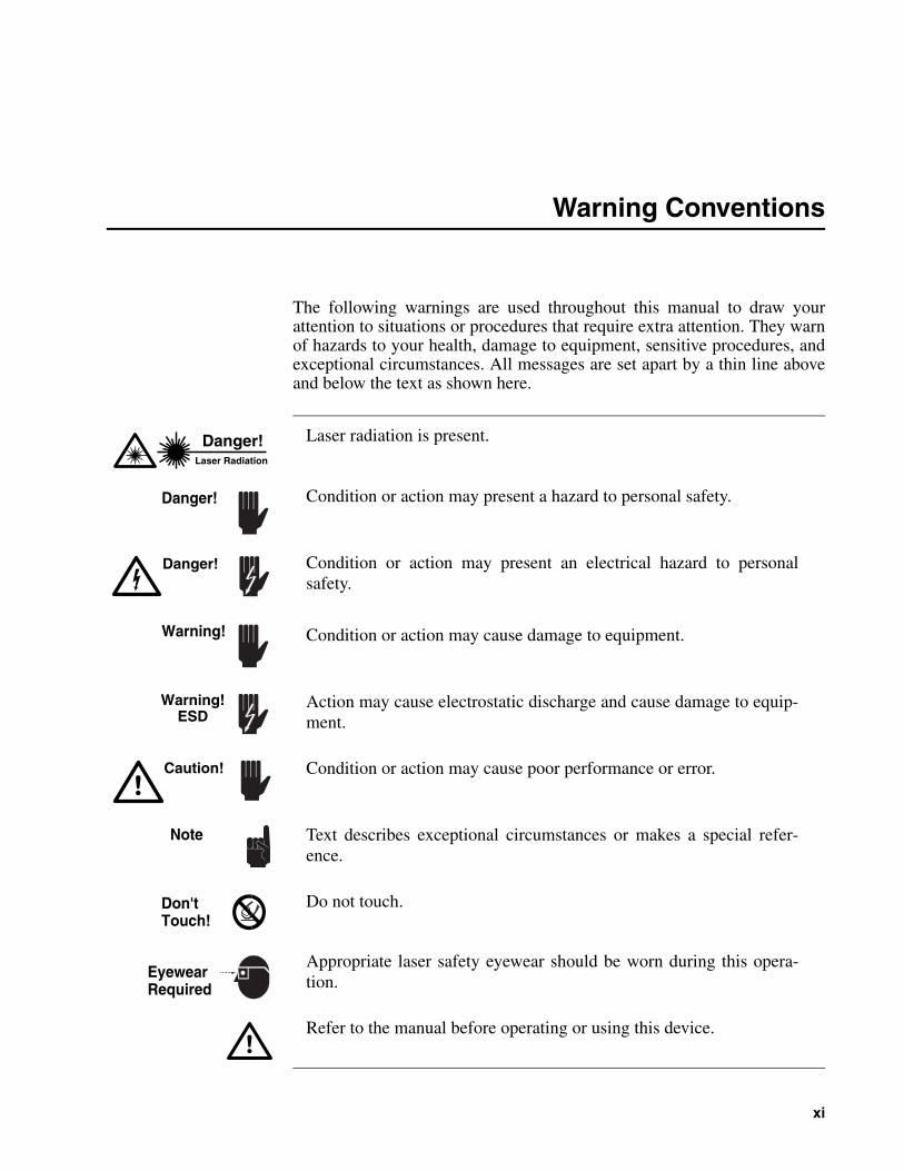
The following warnings are used throughout this manual to draw yourattention to situations or procedures that require extra attention. They warnof hazards to your health, damage to equipment, sensitive procedures, andexceptional circumstances. All messages are set apart by a thin line aboveand below the text as shown here.
Warning!ESD
Laser radiation is present.
Condition or action may present a hazard to personal safety.
Condition or action may cause damage to equipment.
Condition or action may cause poor performance or error.
Text describes exceptional circumstances or makes a special refer-ence.
Do not touch.
Appropriate laser safety eyewear should be worn during this opera-tion.
Danger!
Warning!
Don'tTouch!
EyewearRequired
Note
Condition or action may present an electrical hazard to personalsafety.
Refer to the manual before operating or using this device.
Action may cause electrostatic discharge and cause damage to equip-ment.
Danger!Laser Radiation
Caution!
Danger!


xiii
Standard Units
The following units, abbreviations, and prefixes are used in this Spectra-Physics manual:
Quantity Unit Abbreviation
mass kilogram kg
length meter m
time second s
frequency hertz Hz
force newton N
energy joule J
power watt W
electric current ampere A
electric charge coulomb C
electric potential volt V
resistance ohm Ωinductance henry H
magnetic flux weber Wb
magnetic flux density tesla T
luminous intensity candela cd
temperature Celcius C
Fahrenheit F
pressure pascal Pa
capacitance farad F
angle radian rad
Prefixes
tera (1012) T deci (10-1) d nano (10-9) n
giga (109) G centi (10-2) c pico (10-12) p
mega (106) M mill (10-3) m femto (10-15) f
kilo (103) k micro (10-6) µ atto (10-18) a


xv
Abbreviations
These abbreviations may be found in this manual:
AC alternating current
AOM acousto-optic modulator
APM active pulse mode locking
AR antireflection
bi-fi birefringent filter
CDRH Center of Devices and Radiological Health
CW continuous wave
DC direct current
E/O electro-optic
fs femtosecond or 10-15 second
GTI Gires-Toutnois Interferometer
GVD group velocity dispersion
HR high reflector
IR infrared
OC output coupler
ps picosecond or 10-12 second
PZT piezo-electric transducer
RF radio frequency
SBR saturable Bragg reflector
SCFH standard cubic feet per hour
SPM self phase modulation
TEM transverse electromagnetic mode
Ti:sapphire Titanium-doped Sapphire
UV ultraviolet
λ wavelength

xvii
Unpacking and Inspection
Unpacking Your Laser
Your Evolution-30 laser was packed with great care, and its container wasinspected prior to shipment. If any major damage was noticed at the time ofreceipt (holes in the containers, water damage, crushing, etc.), please notifythe carrier.
If you choose to unpack your laser system, carefully inspect the system asyou do so. If any damage is evident, such as dents or scratches on thecovers or broken parts, immediately notify the carrier and your Spectra-Physics sales representative.
Keep the shipping containers. If you file a damage claim, you may needthem to demonstrate that the damage occurred as a result of shipping. Ifyou need to return the system for service at a later date, the speciallydesigned container assures adequate protection.
The Evolution-30 system is shipped in four crates:
Laser headPower supplyComputer and accessory kitChiller
Each should be carefully opened and unpacked in a clean, dry area. Inspecteach component as you unpack it. To open a crate, remove the clampsaround the top edge of the crate and lift off the top. (The sides are perma-nently fixed to the pallet.)
It is recommended that you wait for your Spectra-Physics representativeto unpack your system. In no event should you attempt to install thelaser yourself, or remove the lid sealing the laser cavity. Either action, ifunauthorized, will void your warranty, and you will be charged for therepair of any damage that may result. Refer to Chapter 4, “SystemInstallation.”
Warning!
Do not turn the crates upside-down or on their sides. Once out of theircrates, do not turn the laser head or the chiller upside-down or on theirsides. Damage to these units may result. Such damage is not covered byyour warranty!
Warning!
Evolution-30 Intracavity-Doubled, Diode-Pumped Nd:YLF Laser
xviii
The laser head is cradled between foam blocks. Remove the laser head andits attached umbilical cord, taking care not to lift the unit using the umbili-cal cord or its attachment. Remove any tie-wraps or tape holding the umbil-ical cable in place. Put the foam blocks back in the shipping crate forstorage.
Remove the laptop computer and accessory box and place them on thetable. The Evolution-30 power supply is strapped to its shipping crate.Remove the straps and carefully lift the power supply out of the crate andplace it on the ground.
The last crate contains the chiller with the filter and hoses already attached.The chiller is strapped to the base of the crate. Remove the straps andcarefully lift the chiller off the base of the crate. DO NOT lift the unit bythe filter or its connecting fixtures.
Accessory Kit
• This Evolution 30 User’s Manual• Laptop computer• One or more beam tube(s)• 4 adjusting feet for the laser head (installed)• A set of Allen head drivers• Serial and power cables for the laptop computer• Power supply power cable• Optishield® corrosion inhibitor/algaecide• Power supply interlock jumper and keys• Spare chiller filter
OptiShield is a registered trademark of Opti Temp, Inc.
1-1
Chapter 1 Introduction
The Evolution-30 is an intracavity-doubled, diode-pumped Nd:YLF laserwith green output at 527 nm. The Q-switched output is pulsed at user-controlled repetition rates that are typically between 1 and 10 kHz. Byusing an internal removable mirror, the user can elect to have the laserbeam exit the Evolution-30 either through the front or side panel of thelaser head. The system is controlled via convenient interface softwareinstalled on the laptop computer that is supplied with the system.
The Evolution-30 system comprises four main elements:
• Evolution-30 laser head• Power supply• Laptop computer and interface software• Closed-loop chiller
The Laser Head
The laser head is a sealed aluminum chassis that contains the followingcomponents:
• Diode-pumped laser chamber• Optical resonator assembly• Two acousto-optic Q-switches• Frequency-doubling crystal and temperature-controlled oven• Safety shutter
The Evolution-30 is available in two versions: OEM and Scientific. Thealuminum chassis of the scientific version is mounted in an externalhousing with an emission indicator and four mounting feet that allow forbeam height adjustment. The OEM version does not include this externalhousing, thus minimizing its footprint and allowing simpler integration ofthe Evolution-30 with other instruments.
The Evolution-30 was designed to provide optimum performance withminimal user intervention. Normal operation should not require the laserhead cover to be opened. Removing the laser head cover without priorauthorization will void the warranty.
Caution!
Evolution-30 Intracavity-Doubled, Diode-Pumped Nd:YLF Laser
1-2
The Power Supply
The power supply contains the electronics required to drive the diodelasers, stabilize the temperature of the doubling crystal, Q-switch the laserand monitor the interlocks. The power supply connects to the laser headthrough a removable 3-meter long umbilical cable. The power supplycontains the following components:
• Master control electronics• Diode laser power supply• Doubling crystal temperature controller• Q-switch driver• Accessory electronics
The Control Computer
The Evolution-30 comes with a commercial laptop computer pre-loadedwith LabVIEW™* software that uses an RS-232 serial interface to controland monitor the functions of the laser. Although the particular computerdelivered with each laser may vary, it is specified to have:
a high-speed CPU≥ 256 MB of RAM≥ 10 GB hard drivea CD-ROM drivea floppy driveWindows XP Home Edition™** operating system
The control software for the Evolution-30 is pre-installed on the laptop andtested with the laser. A copy of this software is delivered on floppy disk orCD-ROM.
The Closed-Loop Chiller
A small closed-loop chiller is provided to dissipate waste heat. In additionit is part of the sub-system that stabilizes the wavelength of the diode lasersto ensure maximum absorption of the pump light in the gain medium. Thechiller has two hoses with quick-release connectors and a pressureregulator valve to reduce the water pressure at the laser head. A chemicaladditive in the distilled water coolant prevents algae growth and corrosion.
The functions of the system and its components are described in detail inChapter 3, “System Overview.”
* LabVIEW is a registered trademark of National Instruments**Windows XP is a registered trademark of Microsoft
2-1
Chapter 2 Laser Safety
This safety section should be reviewed thoroughly prior to operating theEvolution-30 laser system. Safety precautions listed in this manual shouldbe followed carefully.
Hazards
Hazards associated with lasers generally fall into the following categories:
• Exposure to laser radiation which may result in damage to the eyes orskin
• Exposure to chemical hazards such as particulate matter or gaseoussubstances released as a result of laser material processing, or as by-products of the lasing process itself
• Electrical hazards generated in the laser power supply or associatedcircuits
• Secondary hazards such as:
X-radiation from faulty power supplies
Pressurized lamps, hoses, cylinders, etc.
Pressurized liquids and gasses
This user information is in compliance with Section 1040.10 of theCDRH Laser Products Performance Standards from the Health andSafety Act of 1968. Use of controls or adjustments, or performance ofprocedures other than those specified herein, may result in hazardousradiation exposure.
Warning!
The Evolution-30 is a Class IV High Power Laser whose beam is asafety and fire hazard. Take precautions to prevent exposure to direct orreflected beams. Diffuse as well as specular reflections can cause severeeye or skin damage.
Danger!Laser Radiation
Evolution-30 Intracavity-Doubled, Diode-Pumped Nd:YLF Laser
2-2
Optical Safety Precautions
The special nature of laser light poses safety hazards not associated withlight from conventional sources. The safety precautions listed below are tobe read and observed by anyone working with the laser. At all times, ensurethat personnel who operate, maintain or service the laser are protected fromaccidental or unnecessary exposure to laser radiation exceeding the acces-sible emission limits listed in “Performance Standards for Laser Products,”United States Code of Federal Regulations, 21CFR1040 10(d).
The following safety precautions are to be observed at all times:
• Wear protective eyewear at all times; selection depends on the wave-length and intensity of the radiation, the conditions of use, and thevisual function required. Protective eyewear vendors are listed in theLaser Focus World, Lasers and Optronics, and Photonics Spectrabuyer’s guides. Consult the ANSI, ACGIH, or OSHA standards listedat the end of this section for guidance.
• Avoid wearing jewelry or other objects that may reflect or scatter thebeam while using the laser.
• Work in high ambient illumination. This keeps the eye’s pupil con-stricted, thus reducing the possibility of eye damage.
• Never look directly into the laser beam.• Avoid looking at the beam; even diffuse reflections are hazardous.• Use an infrared detector to ascertain whether the laser beam is on or
off before working on the laser.• Work with the lowest beam intensity consistent with the application.• Operate lasers only in well-marked areas with controlled access. Be
sure to post appropriate warning signs, clearly visible.• Limit access to the laser system to qualified personnel who are essen-
tial to its operation and who have been trained in the safety principles.When not in use, lasers should be shut down completely and desig-nated off-limits to unauthorized personnel.
• Provide enclosures for beam paths whenever possible.• Terminate the laser beam with an appropriate energy-absorbing target.• Shield unnecessary reflections and scattered laser radiation.• Avoid blocking the output beam or any reflections with any part of
your body.• Set up the laser so that the beam height is either well above or well
below eye level.
Laser Safety
2-3
Electrical Safety Precautions
The following precautions should be observed by anyone working withpotentially hazardous electrical circuitry:
• Disconnect main power lines before working on any electrical equip-ment when it is not necessary for the equipment to be operating.
• Do not short or ground the power supply output. Protection againstpossible hazards requires proper connection of the ground terminal onthe power cable, and an adequate external ground. Check these con-nections at the time of installation, and periodically thereafter.
• Never work on electrical equipment unless there is another personnearby who is familiar with the operation and hazards of the equip-ment, and who is competent to administer first aid.
• When possible, keep one hand away from the equipment to reduce thedanger of current flowing through the body if a live circuit is touchedaccidentally.
• Always use approved, insulated tools when working on equipment.• Special measurement techniques are required for this system. Ground
references must be selected by a technician who has a complete under-standing of the system operation and associated electronics.
Protective Eye Wear
It is recommended that laser-safe eye wear be worn at all times when theEvolution-30 laser is operating. The eye wear should be attenuated to atleast protect against the following wavelength ranges:
• 1047–1053 nm Covers the fundamental operation wavelength• 523–527 nm Covers the second harmonic wavelength• 794–810 nm Covers wavelength emitted by the diode lasers
During normal operation of the laser the operator will not be exposeddirectly to hazardous diode laser emission. However, removal of themechanical housing cover will not only invalidate your warranty, but willexpose you to hazardous diode laser radiation!
Normal operation of the Evolution-30 should not require access to thepower supply circuitry. Removing the power supply cover will exposethe user to potentially lethal electrical hazards. Contact an authorizedservice representative before attempting to correct any problem with thepower supply.
Danger!
Evolution-30 Intracavity-Doubled, Diode-Pumped Nd:YLF Laser
2-4
CDRH Compliance
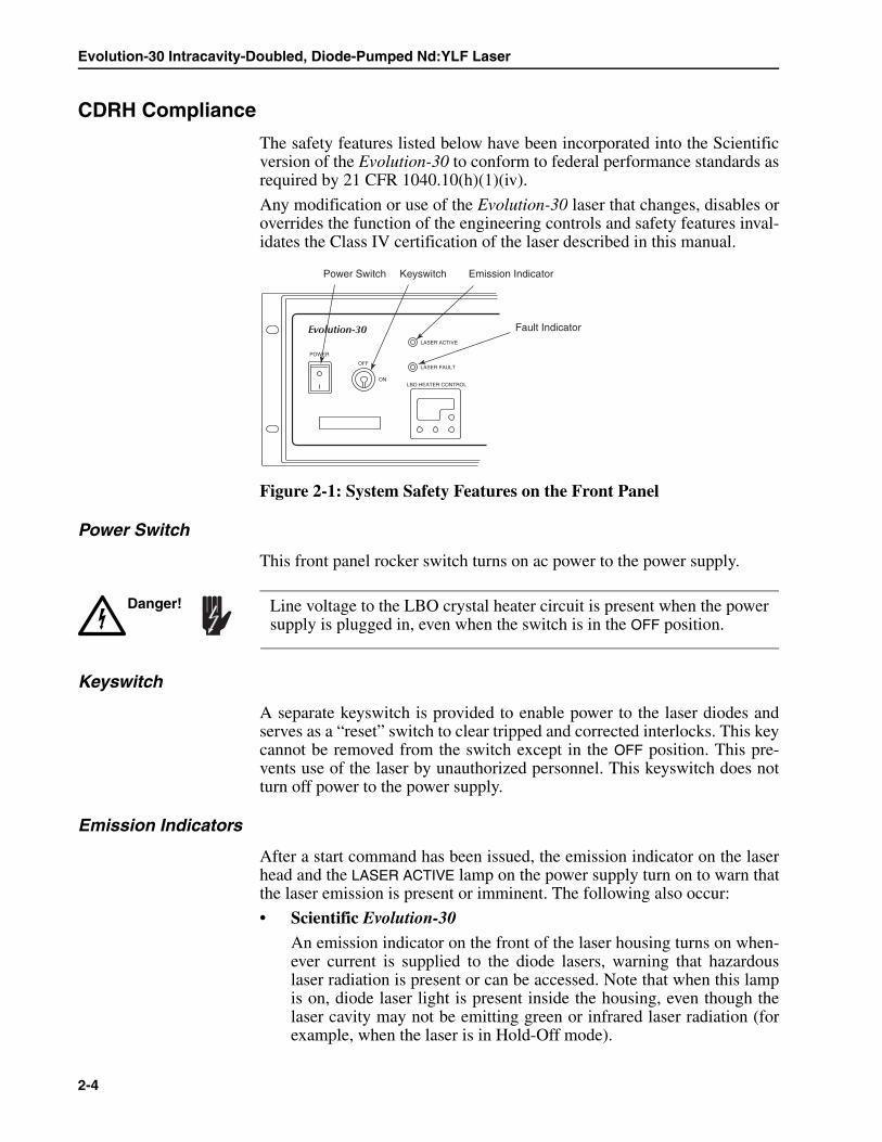
The safety features listed below have been incorporated into the Scientificversion of the Evolution-30 to conform to federal performance standards asrequired by 21 CFR 1040.10(h)(1)(iv).
Any modification or use of the Evolution-30 laser that changes, disables oroverrides the function of the engineering controls and safety features inval-idates the Class IV certification of the laser described in this manual.
Figure 2-1: System Safety Features on the Front Panel
Power Switch
This front panel rocker switch turns on ac power to the power supply.
Keyswitch
A separate keyswitch is provided to enable power to the laser diodes andserves as a “reset” switch to clear tripped and corrected interlocks. This keycannot be removed from the switch except in the OFF position. This pre-vents use of the laser by unauthorized personnel. This keyswitch does notturn off power to the power supply.
Emission Indicators
After a start command has been issued, the emission indicator on the laserhead and the LASER ACTIVE lamp on the power supply turn on to warn thatthe laser emission is present or imminent. The following also occur:
• Scientific Evolution-30
An emission indicator on the front of the laser housing turns on when-ever current is supplied to the diode lasers, warning that hazardouslaser radiation is present or can be accessed. Note that when this lampis on, diode laser light is present inside the housing, even though thelaser cavity may not be emitting green or infrared laser radiation (forexample, when the laser is in Hold-Off mode).
POWER
OFF
ON
Evolution-30LASER ACTIVE
LASER FAULT
LBO HEATER CONTROL
Keyswitch Emission Indicator
Fault Indicator
Power Switch
Line voltage to the LBO crystal heater circuit is present when the powersupply is plugged in, even when the switch is in the OFF position.
Danger!
Laser Safety
2-5
• OEM Evolution-30
A detachable emission indicator (supplied with the laser) can bemounted on the laser head or post-mounted in a remote location. Thisindicator functions in the same way as the permanent indicator on theScientific Evolution-30. To comply with CDRH requirements, it mustbe placed in a clearly visible location no more than 10 feet (~3 m)from the Evolution-30 output port. This indicator is required when theOEM Evolution-30 is installed in an instrument and an indicator on thelaser head is not clearly visible.
All emission indicators remain on as long as the laser is capable of lasing.They illuminate a few seconds prior to actual emission to give nearby per-sonnel time to avoid exposure.
Fault Indicator
When the LASER FAULT indictor turns on, for safety, turn off the laser anddetermine the source of the fault before continuing laser use.
Remote Interlock Connector
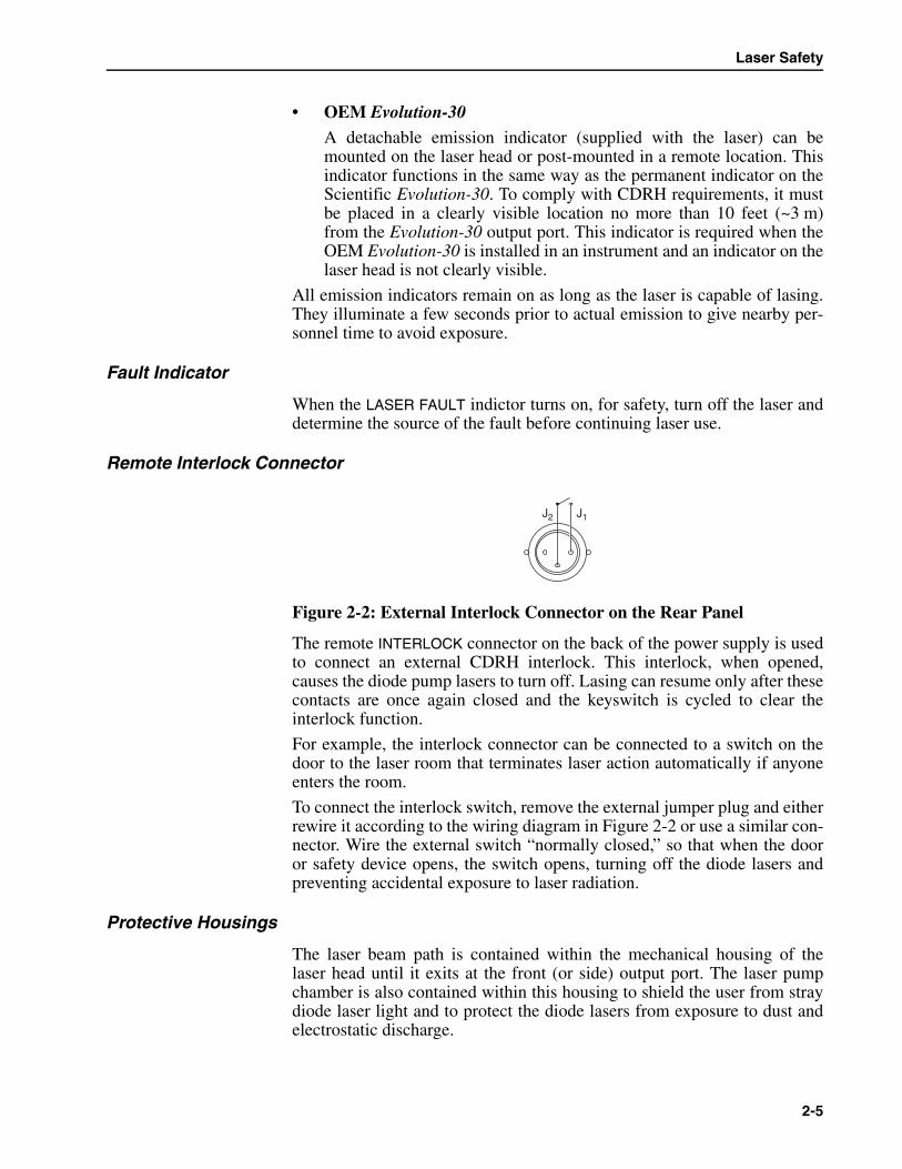
Figure 2-2: External Interlock Connector on the Rear Panel
The remote INTERLOCK connector on the back of the power supply is usedto connect an external CDRH interlock. This interlock, when opened,causes the diode pump lasers to turn off. Lasing can resume only after thesecontacts are once again closed and the keyswitch is cycled to clear theinterlock function.
For example, the interlock connector can be connected to a switch on thedoor to the laser room that terminates laser action automatically if anyoneenters the room.
To connect the interlock switch, remove the external jumper plug and eitherrewire it according to the wiring diagram in Figure 2-2 or use a similar con-nector. Wire the external switch “normally closed,” so that when the dooror safety device opens, the switch opens, turning off the diode lasers andpreventing accidental exposure to laser radiation.
Protective Housings
The laser beam path is contained within the mechanical housing of thelaser head until it exits at the front (or side) output port. The laser pumpchamber is also contained within this housing to shield the user from straydiode laser light and to protect the diode lasers from exposure to dust andelectrostatic discharge.
J1J2
Evolution-30 Intracavity-Doubled, Diode-Pumped Nd:YLF Laser
2-6
Cover Safety Interlocks
Interlock cover switches ensure that the Evolution-30 laser head cannot beoperated if the metal optical cavity cover is not in place and, in the Scien-tific version, if the external sheet metal cover is not in place.
Beam Safety Shutter
A solenoid-activated safety shutter mounted in the optical cavity interruptslaser action when necessary.
By default, when the laser is turned on, either by pressing the ON button orby issuing a software command to turn on the laser, the shutter is activated(closed). The interlock fault and fail-safe mode is the closed position.
Beam Attenuator (Output Port)
The beam from the laser output port can be blocked by a manually-operatedshutter. If the optional side port is used, a metal disc (supplied) can beinserted into that port to block emission.
Location of Controls
The Evolution-30 laser is controlled via the serial interface of a remotecomputer. Software is provided with the laser. If the software terminates,the computer malfunctions or the serial connection is broken, the Evolu-tion-30 will stop lasing within 3 seconds.
Operating Instructions
Chapter 5 contains instructions for safely operating the Evolution-30 laser.
Warning Labels
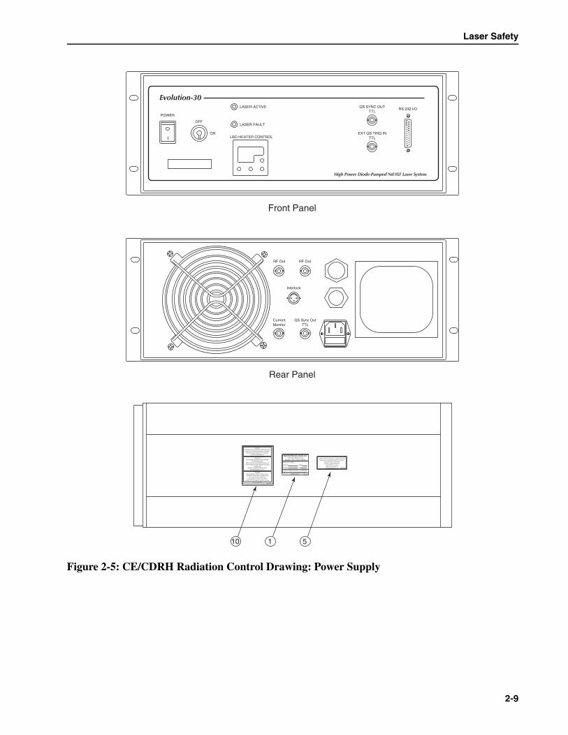
Certification and warning labels are affixed to the Evolution-30 laser toverify compliance with 21 CFR 1040, to provide information on the wave-length and power emitted, and to warn the user against accidental exposureto laser radiation. The location and type of warning logo labels used on theEvolution-30 laser head for the Scientific and OEM versions are shown inFigure 2-3 and Figure 2-4, respectively. Locations of the labels for thepower supply cabinet are shown in Figure 2-5, and the labels themselvesare shown in Figure 2-6.
Translations of the warning labels are provided in Table 2-1 for non-English speaking users. The number in parentheses in the first column cor-responds to the label number in the diagram.
Do not operate the Evolution-30 with any of its covers removed exceptwhen necessary during required service. Removing covers may exposepersonnel to hazardous voltages and radiation. It also increases the rateof optical surface contamination. Removing the cover that protects theoptical cavity will void your warranty.
Danger!

Laser Safety
2-7
CE/CDRH DrawingsLabels are on page 2-10
Figure 2-3: CE/CDRH Radiation Control Drawing: Scientific Version
IN
OUT
Rear View Output End View
Top View
Right Side View
Left Side View
MANUFACTURED:
MONTH
MODEL
YEAR
S/N
THIS LASER PRODUCT COMPLIESWITH 21 CFR 1040 AS APPLICABLE.
MADE IN U.S.A.
Spectra-Physics Lasers, Inc.1344 Terra Bella Avenue
Mountain View, California 94039
0420-7840
1 4
AVOID EXPOSUREVISIBLE AND/ORINVISIBLE LASER
RADIATION IS EMITTEDFROM THIS APERTURE
808-
5276
6 27
4
AVOID EXPOSUREVISIBLE AND/ORINVISIBLE LASER
RADIATION IS EMITTEDFROM THIS APERTURE
808-
5276
VIS
IBLE
AN
D/O
R IN
VIS
IBLE
LAS
ER
RA
DIA
TIO
N W
HE
NO
PE
N A
ND
INT
ER
LOC
KD
EF
EA
TE
D!
AV
OID
EY
E O
R S
KIN
EX
PO
SU
RE
TO
DIR
EC
TO
R S
CA
TT
ER
ED
RA
DIA
TIO
N.
CLA
SS
1V LA
SE
R P
RO
DU
CT
808-7255
VIS
IBLE
AN
D/O
R IN
VIS
IBLE
LAS
ER
RA
DIA
TIO
N W
HE
NO
PE
N A
ND
INT
ER
LOC
KD
EF
EA
TE
D!
AV
OID
EY
E O
R S
KIN
EX
PO
SU
RE
TO
DIR
EC
TO
R S
CA
TT
ER
ED
RA
DIA
TIO
N.
CLA
SS
1V LA
SE
R P
RO
DU
CT
808-7255
808-5326
VISIBLE AND/OR INVISIBLE LASER RADIATIONWHEN OPEN AND INTERLOCK DEFEATED!
AVOID EYE OR SKIN EXPOSURE TO DIRECTOR SCATTERED RADIATION.CLASS IV LASER RADIATION
AVOID EXPOSUREVISIBLE AND/ORINVISIBLE LASER
RADIATION IS EMITTEDFROM THIS APERTURE
808-
5276
AVOID EXPOSUREVISIBLE AND/ORINVISIBLE LASER
RADIATION IS EMITTEDFROM THIS APERTURE
808-
5276AVOID EXPOSURE
VISIBLE AND/ORINVISIBLE LASER
RADIATION IS EMITTEDFROM THIS APERTURE
808-
5276
4 1
45 9 84
MANUFACTURED:
MONTH
MODEL
YEAR
S/N
THIS LASER PRODUCT COMPLIESWITH 21 CFR 1040 AS APPLICABLE.
MADE IN U.S.A.
Spectra-Physics Lasers, Inc.1344 Terra Bella Avenue
Mountain View, California 94039
0420-7840
CAUTIONVISIBLE, INVISIBLE ANDRF ELECTROMAGNETICRADIATION WHEN OPEN.
808-7099
DANGERVISIBLE AND/OR INVISIBLE LASER RADIATION
WHEN OPEN AND INTERLOCK DEFEATED.AVOID EYE OR SKIN EXPOSURE TO DIRECT
OR SCATTERED RADIATION.CLASS 4 LASER PRODUCT
VORSICHTSICHTBARE UND/ODER UNSICHTBARE
LASERSTRAHLUNG, WENN ABDECKUNGGEOFFNET UND SICHERHEITSVERRIEGLUNG
UBERBRUCKT.BESTRAHLUNG VON AUGEN ODER HAUTDURCH DIREKTE OER STREUSTRAHLUNG
VERMEIDEN.LASER KLASSE 4
DANGERRAYONNEMENT LASER VISIBLE ET/OU
INVISIBLE DANGEREUSE EN CAS D'ORVERTURENEUTRALISEE.
EXPOSITION DANGEREUSE DE L'OEIL OU DELA PEAU AU RAYONNEMENT DIRECT OU
DIFFUS.LASER CLASSE 4
808-7098
VISIBLE AND/OR INVISIBLE LASER RADIATION.AVOID EYE OR SKIN EXPOSURE TO DIRECT
OR SCATTERED RADIATION.CLASS IV LASER PRODUCT
MAX OUTPUT < 50 WWAVELENGTH 527 nmPULSELENGTH 200 nm
808-5326
808-5326
VISIBLE AND/OR INVISIBLE LASER RADIATIONWHEN OPEN AND INTERLOCK DEFEATED!
AVOID EYE OR SKIN EXPOSURE TO DIRECTOR SCATTERED RADIATION.CLASS IV LASER RADIATION
5
VIS
IBLE
AN
D/O
R IN
VIS
IBLE
LAS
ER
RA
DIA
TIO
N W
HE
NO
PE
N A
ND
INT
ER
LOC
KD
EF
EA
TE
D!
AV
OID
EY
E O
R S
KIN
EX
PO
SU
RE
TO
DIR
EC
TO
R S
CA
TT
ER
ED
RA
DIA
TIO
N.
CLA
SS
1V
LA
SE
R P
RO
DU
CT
808-
7255
2
VIS
IBLE
AN
D/O
R IN
VIS
IBLE
LAS
ER
RA
DIA
TIO
N W
HE
NO
PE
N A
ND
INT
ER
LOC
KD
EF
EA
TE
D!
AV
OID
EY
E O
R S
KIN
EX
PO
SU
RE
TO
DIR
EC
TO
R S
CA
TT
ER
ED
RA
DIA
TIO
N.
CLA
SS
1V LA
SE
R P
RO
DU
CT
808-7255
5

Evolution-30 Intracavity-Doubled, Diode-Pumped Nd:YLF Laser
2-8
Figure 2-4: CE/CDRH Radiation Control Drawing: OEM Version
Rear View Output End View
Top View
Right Side View
Left Side View
4
AVOID EXPOSUREVISIBLE AND/ORINVISIBLE LASER
RADIATION IS EMITTEDFROM THIS APERTURE
808-
5276
6 2 37
4
808-
5326
VIS
IBLE
AN
D/O
R IN
VIS
IBLE
LA
SE
R R
AD
IAT
ION
WH
EN
OP
EN
AN
D IN
TE
RLO
CK
DE
FE
AT
ED
!A
VO
ID E
YE
OR
SK
IN E
XP
OS
UR
E T
O D
IRE
CT
OR
SC
AT
TE
RE
D R
AD
IAT
ION
.C
LAS
S IV
LA
SE
R R
AD
IAT
ION
VIS
IBLE
AN
D/O
R IN
VIS
IBLE
LAS
ER
RA
DIA
TIO
N W
HE
NO
PE
N A
ND
INT
ER
LOC
KD
EF
EA
TE
D!
AV
OID
EY
E O
R S
KIN
EX
PO
SU
RE
TO
DIR
EC
TO
R S
CA
TT
ER
ED
RA
DIA
TIO
N.
CLA
SS
1V LA
SE
R P
RO
DU
CT
808-7255
VIS
IBLE
AN
D/O
R IN
VIS
IBLE
LAS
ER
RA
DIA
TIO
N W
HE
NO
PE
N A
ND
INT
ER
LOC
KD
EF
EA
TE
D!
AV
OID
EY
E O
R S
KIN
EX
PO
SU
RE
TO
DIR
EC
TO
R S
CA
TT
ER
ED
RA
DIA
TIO
N.
CLA
SS
1V LA
SE
R P
RO
DU
CT
808-7255
808-5326
VIS
IBLE
AN
D/O
R IN
VIS
IBLE
LAS
ER
RA
DIA
TIO
NW
HE
N O
PE
N A
ND
INT
ER
LOC
K D
EF
EA
TE
D!
AV
OID
EY
E O
R S
KIN
EX
PO
SU
RE
TO
DIR
EC
TO
R S
CA
TT
ER
ED
RA
DIA
TIO
N.
CLA
SS
IV LA
SE
R R
AD
IAT
ION
3
AVOID EXPOSUREVISIBLE AND/ORINVISIBLE LASER
RADIATION IS EMITTEDFROM THIS APERTURE
808-
5276
AVOID EXPOSUREVISIBLE AND/ORINVISIBLE LASER
RADIATION IS EMITTEDFROM THIS APERTURE
808-
5276AVOID EXPOSURE
VISIBLE AND/ORINVISIBLE LASER
RADIATION IS EMITTEDFROM THIS APERTURE
808-
5276
4 1
45984
MANUFACTURED:
MONTH
MODEL
YEAR
S/N
THIS LASER PRODUCT COMPLIESWITH 21 CFR 1040 AS APPLICABLE.
MADE IN U.S.A.
Spectra-Physics Lasers, Inc.1344 Terra Bella Avenue
Mountain View, California 94039
0420-7840
CAUTIONVISIBLE, INVISIBLE ANDRF ELECTROMAGNETIC
RADIATION WHEN OPEN.808-7099
DANGERVISIBLE AND/OR INVISIBLE LASER RADIATION
WHEN OPEN AND INTERLOCK DEFEATED.AVOID EYE OR SKIN EXPOSURE TO DIRECT
OR SCATTERED RADIATION.CLASS 4 LASER PRODUCT
VORSICHTSICHTBARE UND/ODER UNSICHTBARE
LASERSTRAHLUNG, WENN ABDECKUNGGEOFFNET UND SICHERHEITSVERRIEGLUNG
UBERBRUCKT.BESTRAHLUNG VON AUGEN ODER HAUTDURCH DIREKTE OER STREUSTRAHLUNG
VERMEIDEN.LASER KLASSE 4
DANGERRAYONNEMENT LASER VISIBLE ET/OU
INVISIBLE DANGEREUSE EN CAS D'ORVERTURENEUTRALISEE.
EXPOSITION DANGEREUSE DE L'OEIL OU DELA PEAU AU RAYONNEMENT DIRECT OU
DIFFUS.LASER CLASSE 4
808-7098
VISIBLE AND/OR INVISIBLE LASER RADIATION.AVOID EYE OR SKIN EXPOSURE TO DIRECT
OR SCATTERED RADIATION.CLASS IV LASER PRODUCT
MAX OUTPUT < 50 WWAVELENGTH 527 nmPULSELENGTH 200 nm
808-5326
OUT
IN
RF1
RF2
PD
AVOID EXPOSUREVISIBLE AND/ORINVISIBLE LASER
RADIATION IS EMITTEDFROM THIS APERTURE
808-
5276
Laser Safety
2-9
Figure 2-5: CE/CDRH Radiation Control Drawing: Power Supply
POWER
OFF
ON
Evolution-30LASER ACTIVE
LASER FAULT
LBO HEATER CONTROL
RS 232 I/OQS SYNC OUT
TTL
EXT QS TRIG INTTL
High Power Diode-Pumped Nd:YLF Laser System
QS Sync OutTTL
CurrentMonitor
Interlock
RF OutRF Out
Front Panel
Rear Panel
DANGERVISIBLE AND/OR INVISIBLE LASER RADIATION.
AVOID EYE OR SKIN EXPOSURE TO DIRECTOR SCATTERED RADIATION. CONSULT
INSTRUCTION MANUAL.CLASS 4 LASER PRODUCT
VORSICHTSICHTBARE UND/ODER UNSICHTBARE
LASERSTRAHLUNG.BESTRAHLUNG VON AUGEN ODER HAUTDURCH DIREKTE OER STREUSTRAHLUNG
VERMEIDEN.NAHERE INFORMATIONEN: SIEHE
BEDIENUNGSANLEITUNG.LASER KLASSE 4
DANGERRAYONNEMENT LASER VISIBLE ET/OUINVISIBLE. EXPOSITION DANGEREUSE
DE L'OEIL OU DE LA PEAU AURAYONNEMENT DIRECT OU DIFFUS.
CONSULTER LE MANUEL D'INSTALLATION.LASER CLASSE 4
808-7097
MANUFACTURED:
MONTH
MODEL
YEAR
S/N
THIS LASER PRODUCT COMPLIESWITH 21 CFR 1040 AS APPLICABLE.
MADE IN U.S.A.
Spectra-Physics Lasers, Inc.1344 Terra Bella Avenue
Mountain View, California 94039
0420-7840
VISIBLE AND/OR INVISIBLE LASER RADIATION.AVOID EYE OR SKIN EXPOSURE TO DIRECT
OR SCATTERED RADIATION.CLASS IV LASER PRODUCT
MAX OUTPUT < 50 WWAVELENGTH 527 nmPULSELENGTH 200 nm
808-5326
10 1 5
Evolution-30 Intracavity-Doubled, Diode-Pumped Nd:YLF Laser
2-10
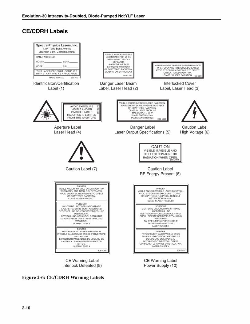
CE/CDRH Labels
Figure 2-6: CE/CDRH Warning Labels
MANUFACTURED:
MONTH
MODEL
YEAR
S/N
THIS LASER PRODUCT COMPLIESWITH 21 CFR 1040 AS APPLICABLE.
MADE IN U.S.A.
Spectra-Physics Lasers, Inc.1344 Terra Bella Avenue
Mountain View, California 94039
0420-7840
Identificaiton/CertificationLabel (1)
Danger Laser BeamLabel, Laser Head (2)
Danger LabelLaser Output Specifications (5)
Aperture LabelLaser Head (4)
CE Warning LabelInterlock Defeated (9)
CE Warning LabelPower Supply (10)
Caution Label RF Energy Present (8)
Caution Label (7)
Caution LabelHigh Voltage (6)
Interlocked CoverLabel, Laser Head (3)
VISIBLE AND/OR INVISIBLELASER RADIATION WHENOPEN AND INTERLOCK
DEFEATED!AVOID EYE OR SKIN
EXPOSURE TO DIRECTOR SCATTERED RADIATION.CLASS IV LASER PRODUCT
808-7255
DANGERVISIBLE AND/OR INVISIBLE LASER RADIATION
WHEN OPEN AND INTERLOCK DEFEATED.AVOID EYE OR SKIN EXPOSURE TO DIRECT
OR SCATTERED RADIATION.CLASS 4 LASER PRODUCT
VORSICHTSICHTBARE UND/ODER UNSICHTBARE
LASERSTRAHLUNG, WENN ABDECKUNGGEOFFNET UND SICHERHEITSVERRIEGLUNG
UBERBRUCKT.BESTRAHLUNG VON AUGEN ODER HAUTDURCH DIREKTE OER STREUSTRAHLUNG
VERMEIDEN.LASER KLASSE 4
DANGERRAYONNEMENT LASER VISIBLE ET/OU
INVISIBLE DANGEREUSE EN CAS D'ORVERTURENEUTRALISEE.
EXPOSITION DANGEREUSE DE L'OEIL OU DELA PEAU AU RAYONNEMENT DIRECT OU
DIFFUS.LASER CLASSE 4
808-7098
DANGERVISIBLE AND/OR INVISIBLE LASER RADIATION.
AVOID EYE OR SKIN EXPOSURE TO DIRECTOR SCATTERED RADIATION. CONSULT
INSTRUCTION MANUAL.CLASS 4 LASER PRODUCT
VORSICHTSICHTBARE UND/ODER UNSICHTBARE
LASERSTRAHLUNG.BESTRAHLUNG VON AUGEN ODER HAUTDURCH DIREKTE OER STREUSTRAHLUNG
VERMEIDEN.NAHERE INFORMATIONEN: SIEHE
BEDIENUNGSANLEITUNG.LASER KLASSE 4
DANGERRAYONNEMENT LASER VISIBLE ET/OUINVISIBLE. EXPOSITION DANGEREUSE
DE L'OEIL OU DE LA PEAU AURAYONNEMENT DIRECT OU DIFFUS.
CONSULTER LE MANUEL D'INSTALLATION.LASER CLASSE 4
808-7097
CAUTIONVISIBLE, INVISIBLE ANDRF ELECTROMAGNETICRADIATION WHEN OPEN.
808-7099
AVOID EXPOSUREVISIBLE AND/ORINVISIBLE LASER
RADIATION IS EMITTEDFROM THIS APERTURE
808-
5276
VISIBLE AND/OR INVISIBLE LASER RADIATION.AVOID EYE OR SKIN EXPOSURE TO DIRECT
OR SCATTERED RADIATION.CLASS IV LASER PRODUCT
MAX OUTPUT < 50 WWAVELENGTH 527 nmPULSE LENGTH 200 µs 808-5326
808-5326
VISIBLE AND/OR INVISIBLE LASER RADIATIONWHEN OPEN AND INTERLOCK DEFEATED!
AVOID EYE OR SKIN EXPOSURE TO DIRECTOR SCATTERED RADIATION.CLASS IV LASER RADIATION

Laser Safety
2-11
Label Translations
For safety, the following translations are provided for non-English speak-ing personnel. The number in parenthesis in the first column corresponds tothe label number listed on the previous page.
Table 2-1: Label Translations
Label # French German Spanish Dutch
Danger Label (2)and
Interlocked Cover Label
(3)
Rayonnement Laser Visible et/ou Invisible en Cas D’Ouverture et lorsque la securité est neutralisée; exposition dangereuse de l’oeil ou de la peau au rayonnement direct ou diffus. Laser de Classe 4.
Sichtbare und/oder unsichtbare Laserstrahlung wenn geöffnet und Sicherheitsverrie-gelung überbruckt. Bestrahlung von Augen oder Haut durch direkt oder Streustrahlung vermeiden. Laser Klasse 4.
Al abrir y retirar el dispositivo de seguridad exist radiacion laser visible y invisible; evite que los ojos o la piel queden expuestos tanto a la radiacion directa como a la dispersa. Producto laser clase 4.
Zichtbare en onzichtbare laserstraling! Vermijd blootstelling van oog of huid ann direkte straling of terugkaatsingen daarvan! Klas 4 laser produkt.
Aperture Label (4)
Exposition Dangereuse! Rayonnement visible et/ou invisible est emis par cette ouverture
Austritt von sichtbarer und unsichtbarer Laserstrahlung. Bestrahlung vermeiden!
Por esta abertura se emite radiacion laser visible e invisible; evite la exposicion
Vanuit dit apertuur wordt zichtbare en onzichtbare laserstraling geemiteerd! Vermijd blootstelling!
Danger LabelOutput
Specifications(5)
Visible et/ou invisible radiation laser. Evitez l’exposition de la peau de vos yeux et de votre peau au rayonnement directe ou diffuse. Appareil laser de classe IV. Puissance max.: < 50 W, Longueur d’onde: 527 nm, Largeur de pulse: < 200 µs.
Sichtbare und/oder unsichtbare Laserstrahlung! Augen- oder Hautkontakt mit direckter oder Streustrahlung vermeiden!Product der Laser-klasse IV, Max. Ausgangsleistung: < 50 W, Wellenlaenge: 527 nm, Pulsdauer: < 200 µs.
Radiación laser visible y/o invisible. Evitar la exposición directa o dispersada de radiación con los ojos o piel. Clase IV Producto Laser, Máxima Salida: < 50 W, Longitud de ondo: 527 nm, Logitde de pulso: < 200 µs.
Zichtbare en/of onzichtbare laserstraling. Vermijd oog-en huidcontact van de directe en indirecte Straling. Klasse IV laserapparatuur.Maximaal uitgangsvermogen: < 50 W,Golflengte: 527 nm,Pulsduur 200 µs.
Caution LabelRF Energy
Present(8)
Attention. Radiation laser visible et invisible rayonnement RF, capot ouvert.
Vorsicht! Austritt von sichtbarer, unsichtbarer und Hochfrequenzstrahlung, wenn geoeffnet.
Precaucion. Radiacion magnetica visible, invisible y de radio frecuencia si abierto.
Opgepast zichtbare, onzichtbare en hoogfrequent elektromagnetische Straling bij het openen.
Evolution-30 Intracavity-Doubled, Diode-Pumped Nd:YLF Laser
2-12
CDRH Requirements and RS-232 Control
The Evolution-30 and its power supply comply with CDRH safety stan-dards that apply to operating the laser through an RS232 interface. A soft-ware indicator shows when laser radiation is present or can be accessed.
Maintenance Required for CDRH Compliance
This section lists the maintenance required to keep this laser product incompliance with CDRH regulations.
This laser product complies with Title 21 of the United States Code of Fed-eral Regulations, Chapter 1, Sub-chapter J, Parts 1040.10 and 1040.11, asapplicable. To maintain compliance, verify the operation of all featureslisted below, either annually or whenever the product has been subjected toadverse environmental conditions (e.g., fire, flood, mechanical shock,spilled solvents). This maintenance is to be performed as outlined below.
• Verify that removing the laser cover closes the intracavity shutter.• Verify that all the warning labels listed in Figure 2-3, Figure 2-4 and
Figure 2-5 are present and firmly affixed in the correct locations.• Verify that removing the INTERLOCK connector on the rear panel of
the power supply prevents operation of the laser.• Verify that the time delay between illumination of the emission indica-
tor and start of laser emission gives enough warning to allow personnelto avoid exposure to the radiation.
• Verify that the internal beam attenuator (shutter):
a. operates properly when the laser is turned off from the computercontroller,
b. closes when the keyswitch is turned off, and
c. blocks access to laser radiation.

Laser Safety
2-13
CE Declaration of Conformity
We,
Spectra-Physics1330 Terra Bella AvenueMountain View, CA. 94043United States of America
declare under our sole responsibility that the:
Evolution-30 diode-pumped, intracavit-doubled Nd:YLF laser systemwith power supply, and compliant pc-based controller, and Neslabor Lytron chiller
manufactured after July 1999.
to which this declaration relates is in conformance with:
the provisions of Directive 73/23/EEC governing product safety using thefollowing standards:
EN 60950: 1997EN 61010-1: 2001EN 60825-1: 1994
the provisions of Directive 89/336/EEC governing electromagnetic compati-bility using the following standards:
EN 61326-1 w/A1: 1997
I, the undersigned, hereby declare that the equipment specified above con-forms to the above Directives and Standards.
Bruce CraigVice President and General ManagerSpectra-PhysicsLaser GroupApril 5, 2002Mountain View, CaliforniaUSA
Evolution-30 Intracavity-Doubled, Diode-Pumped Nd:YLF Laser
2-14
Sources for Additional Information
The following are some sources for additional information on laser safetystandards, safety equipment, and training.
Laser Safety Standards
Safe Use of Lasers (Z136.1: 1993)American National Standards Institute (ANSI)11 West 42nd StreetNew York, NY 10036Tel: (212) 642-4900
Occupational Safety and Health Administration (Publication 8.1-7)U. S. Department of Labor200 Constitution Avenue N. W., Room N3647Washington, DC 20210Tel: (202) 693-1999
A Guide for Control of Laser Hazards, 4th Edition, Publication #0165American Conference of Governmental andIndustrial Hygienists (ACGIH)1330 Kemper Meadow DriveCincinnati, OH 45240Tel: (513) 742-2020Internet: www.acgih.org/home.htm
Laser Institute of America13501 Ingenuity Drive, Suite 128Orlando, FL 32826Tel: (800) 345-2737Internet: www.laserinstitute.org
Compliance Engineering70 Codman Hill RoadBoxborough, MA 01719Tel: (978) 635-8580
International Electrotechnical CommissionJournal of the European CommunitiesEN60825-1 TR3 Ed.1.0—Laser Safety Measurement and InstrumentationIEC-309—Plug, Outlet and Socket Coupler for Industrial UsesTel: +41 22-919-0211Fax: +41 22-919-0300Internet: http://ftp.iec.c.h/
CenelecEuropean Committee for Electrotechnical StandardizationCentral Secretariatrue de Stassart 35B-1050 Brussels
Document Center1504 Industrial Way, Unit 9Belmont, CA 94002-4044Tel: (415) 591-7600
Laser Safety
2-15
Equipment and Training
Laser Safety GuideLaser Institute of America12424 Research Parkway, Suite 125Orlando, FL 32826Tel: (407) 380-1553
Laser Focus World Buyer's GuideLaser Focus WorldPenwell Publishing10 Tara Blvd., 5th FloorNashua, NH 03062Tel: (603) 891-0123
Lasers and Optronics Buyer's GuideLasers and OptronicsGordon Publications301 Gibraltar DriveP.O. Box 650Morris Plains, NJ 07950-0650Tel: (973) 292-5100
Photonics Spectra Buyer's GuidePhotonics SpectraLaurin PublicationsBerkshire CommonPO Box 4949Pittsfield, MA 01202-4949Tel: (413) 499-0514

Evolution-30 Intracavity-Doubled, Diode-Pumped Nd:YLF Laser
2-16
3-1
Chapter 3 System Overview
The heart of the Evolution-30 system is an Nd:YLF laser rod pumped bythree sets of four AlGaAs diode laser arrays (twelve arrays total). The laserlight produced by the Nd:YLF laser rod is “frequency-doubled” to greenlight and emitted as energetic Q-switched pulses. The Q-switched pulserepetition rate is controlled by the user at rates from 1 to 10 kHz.
The laser pump chamber contains the Nd:YLF laser rod and diode lasers.The diode lasers “pump” the Nd:YLF rod; that is, their output excites theelectrons of the neodymium atoms in the YLF crystal, which emit the1053 nm light characteristic of their laser transition. The mirrors in theEvolution-30 laser cavity are all highly reflective of 1053 nm radiation, soit is entirely contained inside the resonator.
This light is Q-switched by means of acousto-optic modulators to producepulses from 100 to 350 ns long. The pulse duration depends on the pulserepetition rate and pump level, which are selected by the user.
The Evolution-30 green output at 527 nm is produced by passing Nd:YLF-generated light through the frequency-doubling LBO (lithium triborate)crystal. In order to maximize the conversion of the fundamental wavelengthto the green harmonic, the LBO crystal is placed inside the laser cavitywhere the fundamental beam is most intense (the conversion efficiencyincreases rapidly with the intensity of the fundamental light input). LBOoffers excellent efficiency and a high damage threshold.
These 527 nm pulses exit the laser head from the forward output port orfrom the side output port if the internal turning mirror is used. The Evolu-tion-30 is ideally suited for pumping Ti:sapphire ultrafast amplifiers.
Nd:YLF Laser Material
The Evolution-30 uses neodymium-doped lithium yttrium fluoride(Nd:LiYF4, most commonly abbreviated as Nd:YLF) as its gain medium.Its long upper-state lifetime (470 µs) provides efficient energy storage forhigh pulse energy operation at low repetition rates. The low thermal lensingand natural birefringence of Nd:YLF enable scaling to higher power with-out the loss of beam quality or the need for complex resonator designs.
As a birefringent material, Nd:YLF lases at two principle wavelengths: the1047 nm (extraordinary) or the 1053 nm (ordinary) transition. Both linesoriginate on the same Stark split 4F3/2 upper level. The good thermal con-ductivity of Nd:YLF allows efficient heat extraction, and its natural bire-fringence overwhelms thermally induced birefringence, eliminating thethermal depolarization problems of optically isotropic hosts like Nd:YAG.

Evolution-30 Intracavity Doubled, Diode-Pumped Nd:YLF Laser
3-2
The 1053 nm transition is used in the Evolution-30 because of the some-what higher absorption of the pump light by this transition, resulting inlower heat generation and, therefore, lower thermal lensing.
Acousto-Optic Q-Switching
An acousto-optic modulator (AOM) is a block of fused silica that acts as anoptical phase grating when vibrated by an ultrasonic wave. The photoelas-tic effect couples the strain field of the ultrasonic wave to the optical indexof refraction in the block. The resultant optical grating has a period and anamplitude set by the acoustic (ultrasonic) wavelength.
When a light beam is incident upon this grating, a portion of the intensity isdiffracted out of the beam. By choosing beam parameters properly, a por-tion of any laser beam that attempts to circulate within the resonator experi-ences a diffraction loss that is sufficient to spoil the “Q” of the cavity andprevent lasing (i.e., there is no circulating beam).
With no circulating laser light available to pass through the laser medium,the pump energy builds up the gain to a higher level than would otherwisebe present. (This is where the long lifetime of the upper-state laser level ofNd:YLF is beneficial).
The ultrasonic wave is impressed on the AOM by a piezo-electric trans-ducer. Switching off the driving voltage to the transducer returns the AOMto its passive state of high optical transmission, and the laser resonator isreturned to its high Q-state. The internal beam is no longer deflected but,instead, is amplified by the high gain now available in the Nd:YLF rod, anda powerful “Q-switched” laser pulse is emitted.
Re-applying voltage to the AOM with the transducer again spoils the cavityQ and allows the gain to rebuild to a high level. In order to hold off the veryhigh circulating intensity in the Evolution-30, two synchronized AOMs areused. This process is repeated at the frequency at which pulsed laser outputis desired, taking into consideration the characteristics of the laser.
Figure 3-1: Acousto-Optic Modulation
CavityEndMirror
Piezo-ElectricTransducer
System Overview
3-3
Intracavity Frequency Doubling
Efficient frequency doubling requires power densities that are not normallyavailable from a CW-pumped laser. Placing the nonlinear doubling crystalinside the resonator exposes it to high circulating power density. Power iscoupled out of the resonator at the second harmonic wavelength by usingan output mirror that is 100% reflective at the fundamental wavelength buttransmits the second harmonic wavelength.
Intracavity frequency-doubling itself behaves in a manner that is somewhatanalogous to an output coupler in a normal laser. It is only necessary thatthe conversion efficiency equals the theoretical optimum mirror transmis-sion in order to completely convert the fundamental 1053 nm Nd:YLFwavelength into the green 527 nm second harmonic.
In order to achieve frequency-doubled output, the fundamental and secondharmonic light must be “phase-matched” within the crystal; that is, the1053 nm and the 527 nm waves must be in phase with each other over areasonable length of the crystal. In order for this to occur, the index ofrefraction of the crystal must be the same at both the fundamental and thefrequency-doubled wavelengths. However, since the wavelengths are sub-stantially different, the two beams will be out of phase since each will see adifferent value for the index of refraction (unless special techniques areemployed). Non-critical phase matching relies on the temperature depen-dence of the dispersion of the crystal to provide a match in the refractiveindex at the two wavelengths. As the name implies, non-critical phasematching is much less sensitive to the alignment of the crystal than otherphase-matching schemes.
Lithium triborate (LBO) is a nonlinear optical crystal characterized by arelatively high optical damage threshold and a moderate nonlinear opticalcoefficient, as well as excellent material properties. LBO’s small birefrin-gence allows for non-critical phase matching and provides a larger accep-tance angle for high efficiency frequency conversion. The crystal must beheated and temperature-stabilized to maintain good conversion efficiency.
Laser Head Configuration
The laser head of the Evolution-30 is shown in Figure 3-2. The laser reso-nator is a folded design, which reduces the overall size of the Evolution-30while simultaneously providing for efficient output coupling of the secondharmonic light. The laser resonator contains the following components:
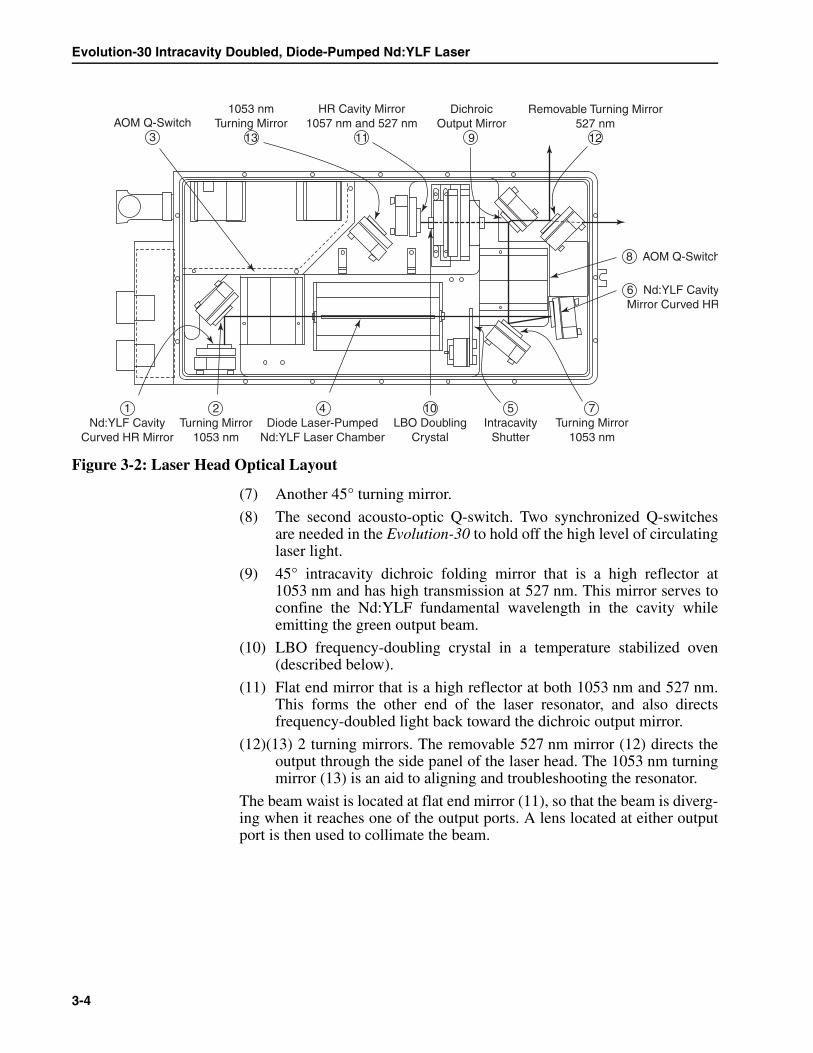
(1) Nd:YLF curved, high reflecting (HR) mirror. This forms one end ofthe laser resonator.
(2) 45° turning mirror, used to decrease the size of the laser head foot-print.
(3) The first AOM Q-switch (described below).
(4) Diode laser pumped Nd:YLF laser chamber (described below).
(5) Intracavity safety shutter.
(6) Curved intracavity mirror, used to shape the beam inside the Nd:YLFrod.
Evolution-30 Intracavity Doubled, Diode-Pumped Nd:YLF Laser
3-4
Figure 3-2: Laser Head Optical Layout
(7) Another 45° turning mirror.
(8) The second acousto-optic Q-switch. Two synchronized Q-switchesare needed in the Evolution-30 to hold off the high level of circulatinglaser light.
(9) 45° intracavity dichroic folding mirror that is a high reflector at1053 nm and has high transmission at 527 nm. This mirror serves toconfine the Nd:YLF fundamental wavelength in the cavity whileemitting the green output beam.
(10) LBO frequency-doubling crystal in a temperature stabilized oven(described below).
(11) Flat end mirror that is a high reflector at both 1053 nm and 527 nm.This forms the other end of the laser resonator, and also directsfrequency-doubled light back toward the dichroic output mirror.
(12)(13) 2 turning mirrors. The removable 527 nm mirror (12) directs theoutput through the side panel of the laser head. The 1053 nm turningmirror (13) is an aid to aligning and troubleshooting the resonator.
The beam waist is located at flat end mirror (11), so that the beam is diverg-ing when it reaches one of the output ports. A lens located at either outputport is then used to collimate the beam.
1053 nmTurning Mirror
13
2Turning Mirror
1053 nm
HR Cavity Mirror1057 nm and 527 nm
11
DichroicOutput Mirror
9
Removable Turning Mirror527 nm
12AOM Q-Switch
3
8 AOM Q-Switch
6 Nd:YLF CavityMirror Curved HR
5Intracavity
Shutter
10LBO Doubling
Crystal
4Diode Laser-Pumped
Nd:YLF Laser Chamber
1Nd:YLF Cavity
Curved HR Mirror
7Turning Mirror
1053 nm

System Overview
3-5
Component Descriptions
Laser Pump Chamber
The laser pump chamber contains the Nd:YLF laser rod and diode lasers.The chamber is mounted to the laser head in a mechanically indexedbracket that allows for easy extraction and insertion of the chamber. Thelaser rod is held with O-rings in a water flow tube that is surrounded by agold-coated reflector. Slits in the reflector transmit the pump light from thediode lasers along the length of the rod. Both the laser rod and diode lasersare cooled by water that enters the pump chamber through manifolds in thebottom of the chamber.
The diode lasers themselves are arranged in three blocks of four high-power diode laser bars that are mounted 120° apart around the laser rod.Each block of bars is attached to a single water-cooled heat sink. The waterflows in four separate parallel channels; one along the laser rod and threeover the diode laser heat sinks. The diode lasers are electrically connectedin series to the Evolution-30 diode laser driver through a high-current con-nector on the pump chamber.
AOM Q-Switches
Two AOMs that function as Q-switches are enclosed in metal housingswith coarse azimuthal adjustments. The AOMs are made of a high-qualityfused silica to which RF transducers are bonded. The fused silica is cut andpolished to be optically oriented at Brewster’s angle for “s” polarized intra-cavity laser radiation.
Approximately 30 Watts of RF power are delivered to each AOM throughtwo 50-ohm BNC cables. The AOMs are water cooled and have built-intemperature interlocks to shut off the RF power if an over-temperature con-dition occurs. The power for the AOM Q-switches is supplied from theEvolution-30 power supply.
LBO Crystal and Temperature Controller
The LBO crystal is anti-reflection coated for both 1053 nm and 527 nm. Itis located in an oven that maintains its temperature at a value set at the fac-tory between 315° and 340°F, to within 0.1°F. At this factory-set temperaturethe crystal is non-critically phase matched for converting the intracavity1053-nm wavelength efficiently to the second harmonic. The crystal shouldbe constantly stabilized in this temperature range, even when the laser isnot in use. If necessary, the crystal can be ramped down to room tempera-ture for long-term storage of the laser (see Chapter 5, “System Operation”).
The temperature controller is a pre-programmed microprocessor-basedinterlock device. If the LBO temperature is outside of the range of the fac-tory set point (threshold values are also set at the factory), an indicatorlamp will come on and an interlock will prevent operation of the laser.
Evolution-30 Intracavity Doubled, Diode-Pumped Nd:YLF Laser
3-6
Power Supply
The power supply assembly consists of a rugged steel frame in a 19 in.rack-mount configuration. The power supply contains the master controlboard, diode power supply, Q-switch RF driver, LBO crystal temperaturecontroller, and other control electronics. In general, it should not be neces-sary to access any components inside the power supply.
Smart Analog PC Board
The master control pc board or “Smart Analog Board” (SAB) is a micro-processor-controlled system for setting and monitoring the diode laserpower supply, laser interlocks, and Q-switch driver. It is controlled by soft-ware on the supplied computer through the RS-232 serial interface.
Diode Laser Power Supply
The diode laser power supply, which is controlled and monitored by theSAB, is a self-contained unit enclosed in a metal housing. The housing pro-tects both service personnel and the components in the power supply.
Q-Switch Driver
The Q-switch driver provides RF power to the Q-switches in the laser head.It is an all solid-state electronic device consisting of a crystal-controlledoscillator, double-balanced modulator, pulse generator with gate and a broadband power amplifier that provides >30 W of drive power into each Q-switch. The driver is controlled and monitored by the SAB.
LBO Crystal Temperature Controller
The LBO doubling crystal is temperature tuned for non-critical phasematching. The crystal is housed in a temperature-stabilized oven. A resis-tive heating element combined with a local temperature sensor is used withthe heater controller to stabilize the crystal temperature to within ±0.1° F.The heater controller is programmed to limit the rate at which the crystaltemperature is changed (typically no faster than 4° F per minute) to preventcracking the crystal anti-reflection coatings. The power for the temperaturecontroller is wired directly to the ac power lines so that the crystal is keptheated even when the front-panel breaker is turned off. The LBO crystaltemperature should be ramped down before disconnecting power to thechassis (see Chapter 5, “System Operation,” for instructions).
Potentially lethal voltages and currents are contained in the powersupply. Removing the power supply cover will expose these hazards.Normal operation of the Evolution-30 does not require access to thepower supply circuitry. Contact an authorized service representativebefore attempting to correct any problem with the power supply.
Danger!
System Overview
3-7
The Control Computer
The Evolution-30 comes with a commercial laptop computer pre-loadedwith LabVIEW™* software that uses an RS-232 serial interface to controland monitor the functions of the laser. Although the particular computerdelivered with each laser may vary, it is specified to have:
a high-speed CPU≥ 256 MB of RAM≥ 10 GB hard drivea CD-ROM drivea floppy driveWindows XP Home Edition™** operating system
The control software for the Evolution-30 is pre-installed on the laptop andtested with the laser. A copy of this software is delivered on floppy disk orCD-ROM.
RS-232 Connection
The control computer is connected to the Evolution-30 power supply usingthe DB-9F to DB-25M serial modem cable. By default, the software usesthe COM1 serial connection on the laptop computer corresponding to thebuilt-in serial port.
Control Software
The “Evolution-30 Control” software is accessed by a shortcut in the Startmenu program folder. The exact layout of the front panel varies dependingon the software version, but all versions share the same general controls.The latest version of the software is always available from Spectra-Physics.
* LabVIEW is a registered trademark of National Instruments**Windows XP is a registered trademark of Microsoft
The Evolution-30 was built and tested using the control computer andcontrol software shipped with the laser. Use of any other computer orsoftware for this purpose may cause damage to the laser, and may alsovoid the warranty.
Caution!
Some laptops provided with the Evolution-30 system do not have serialports. A USB-to-serial adapter is provided with these laptops.
Note
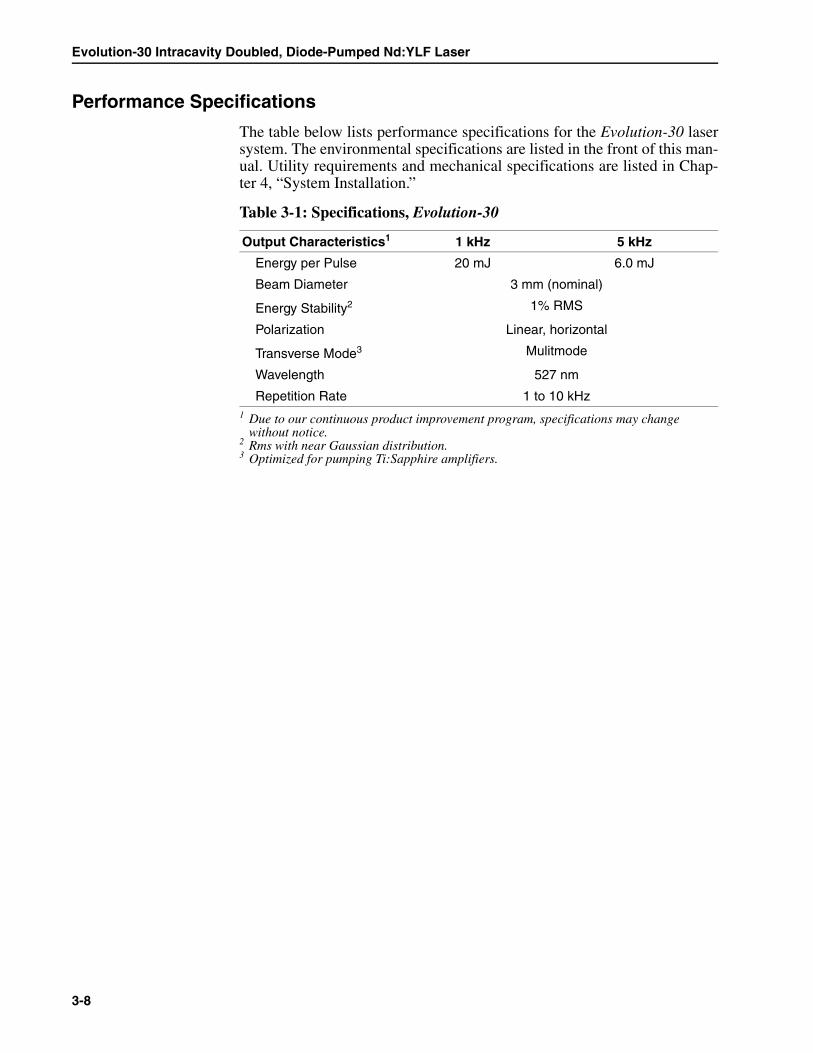
Evolution-30 Intracavity Doubled, Diode-Pumped Nd:YLF Laser
3-8
Performance Specifications
The table below lists performance specifications for the Evolution-30 lasersystem. The environmental specifications are listed in the front of this man-ual. Utility requirements and mechanical specifications are listed in Chap-ter 4, “System Installation.”
Table 3-1: Specifications, Evolution-30
Output Characteristics1
1 Due to our continuous product improvement program, specifications may change without notice.
1 kHz 5 kHz
Energy per Pulse 20 mJ 6.0 mJ
Beam Diameter 3 mm (nominal)
Energy Stability2
2 Rms with near Gaussian distribution.
1% RMS
Polarization Linear, horizontal
Transverse Mode3
3 Optimized for pumping Ti:Sapphire amplifiers.
Mulitmode
Wavelength 527 nm
Repetition Rate 1 to 10 kHz
4-1
Chapter 4 System Installation
The Evolution-30 system must be installed by an authorized Spectra-Physicsrepresentative. Read this section thoroughly beforehand to prepare yoursite for installation, then call your authorized service representative toarrange an installation appointment, which is included as part of your pur-chase agreement. You may, however, unpack the laser and locate it in thearea where it will be used. Refer to the unpacking instructions near thebeginning of this manual.
Location
Before installation, please select a suitable location for the Evolution-30.Spectra-Physics recommends the laser be located in a laboratory type envi-ronment that is free from dust and drafts, with low humidity (<50%) andhas temperature fluctuations less than ±5ºC.
Pumping a Spitfire Amplifier
If used to pump a Spitfire amplifier, the Evolution-30 should be placed rel-atively close to the Spitfire. The optimal distance between the two units isdetermined at the factory during the final test procedure. Deviations ofgreater than 6 inches from this distance can affect the overall performanceof the system. Also, for safety reasons it is inadvisable to allow an exposedlaser beam to travel a long distance. Please consult with your authorizedservice representative if necessary.
Required Utilities
Do not attempt to install the laser yourself, or remove the lid sealing thelaser cavity. Either action, if unauthorized, will void your warranty, andyou will be charged for the repair of any damage that may result.
Warning!
Do not apply ac line power to the power supply. Doing so will activatethe LBO crystal heater. Any improper programming of the crystal heaterand subsequent crystal heating will permanently damage the crystal.Such damage is not be covered under the warranty. Installation of theEvolution-30 laser should be performed by a service engineer.
Warning!
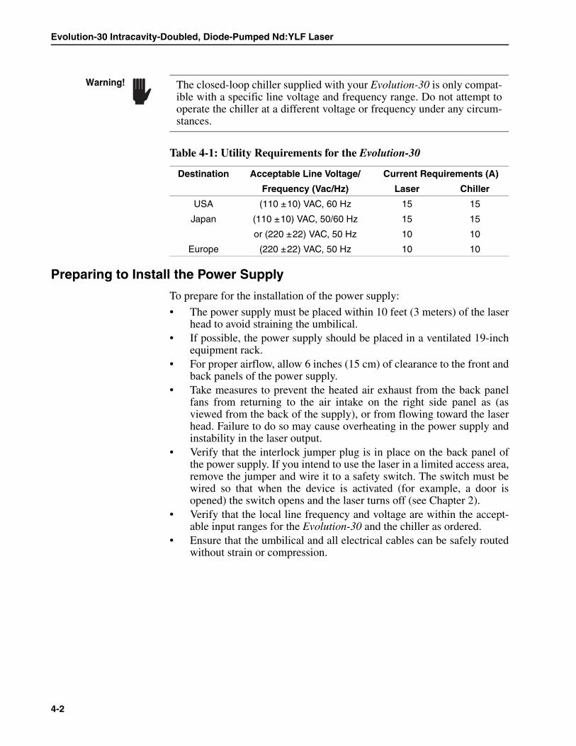
Evolution-30 Intracavity-Doubled, Diode-Pumped Nd:YLF Laser
4-2
Preparing to Install the Power Supply
To prepare for the installation of the power supply:
• The power supply must be placed within 10 feet (3 meters) of the laserhead to avoid straining the umbilical.
• If possible, the power supply should be placed in a ventilated 19-inchequipment rack.
• For proper airflow, allow 6 inches (15 cm) of clearance to the front andback panels of the power supply.
• Take measures to prevent the heated air exhaust from the back panelfans from returning to the air intake on the right side panel as (asviewed from the back of the supply), or from flowing toward the laserhead. Failure to do so may cause overheating in the power supply andinstability in the laser output.
• Verify that the interlock jumper plug is in place on the back panel ofthe power supply. If you intend to use the laser in a limited access area,remove the jumper and wire it to a safety switch. The switch must bewired so that when the device is activated (for example, a door isopened) the switch opens and the laser turns off (see Chapter 2).
• Verify that the local line frequency and voltage are within the accept-able input ranges for the Evolution-30 and the chiller as ordered.
• Ensure that the umbilical and all electrical cables can be safely routedwithout strain or compression.
Table 4-1: Utility Requirements for the Evolution-30
Destination Acceptable Line Voltage/ Current Requirements (A)
Frequency (Vac/Hz) Laser Chiller
USA (110 ±10) VAC, 60 Hz 15 15
Japan (110 ±10) VAC, 50/60 Hz 15 15
or (220 ±22) VAC, 50 Hz 10 10
Europe (220 ±22) VAC, 50 Hz 10 10
The closed-loop chiller supplied with your Evolution-30 is only compat-ible with a specific line voltage and frequency range. Do not attempt tooperate the chiller at a different voltage or frequency under any circum-stances.
Warning!
System Installation
4-3
Preparing to Install the Laser Head
To prepare for the installation of the laser head:
Note that the laser head is attached to the power supply via a 10-foot(3 meters) long umbilical. There are 4 cables inside: a 4-pin currentcable, a 26-pin signal cable, and two BNC cables that connect to theRF OUT connectors on the back of the power supply.
To secure the laser head on an optical table or other flat mounting surface:
OEM Evolution-30
Two slots are provided at the center of the front and back of the laserhousing for securing the laser head using standard table screws (M6 or¼-20) to fasten the laser to the table.
The arm at the front of the laser is bolted in place last, since securingthis first will defeat its purpose in allowing for thermal expansion orcontraction of the housing.
Scientific Evolution-30
Place the laser head on the table and adjust the four mounting feet tothe correct height, making sure that the laser head is level. Lock theheight of the feet using the locking ring on each leg. Secure the laserhead to the table using a mounting clamp (supplied) on each foot.
Preparing to Install the Control Computer
The Evolution-30 control computer needs to be within 10 feet (3 meters) ofthe power supply. The computer should be set up according to the manufac-turer’s instructions. Attach the 9-pin connector of the Evolution-30 serialcable to the computer’s serial output port, and attach the 25-pin connectorto the RS-232 port on the power supply. For control computers shippedwith Windows 2000, the default user name is “Administrator” and thedefault password is “PASS” (case-sensitive, no quotation marks). The Evo-lution-30 control software is pre-installed on the control computer.
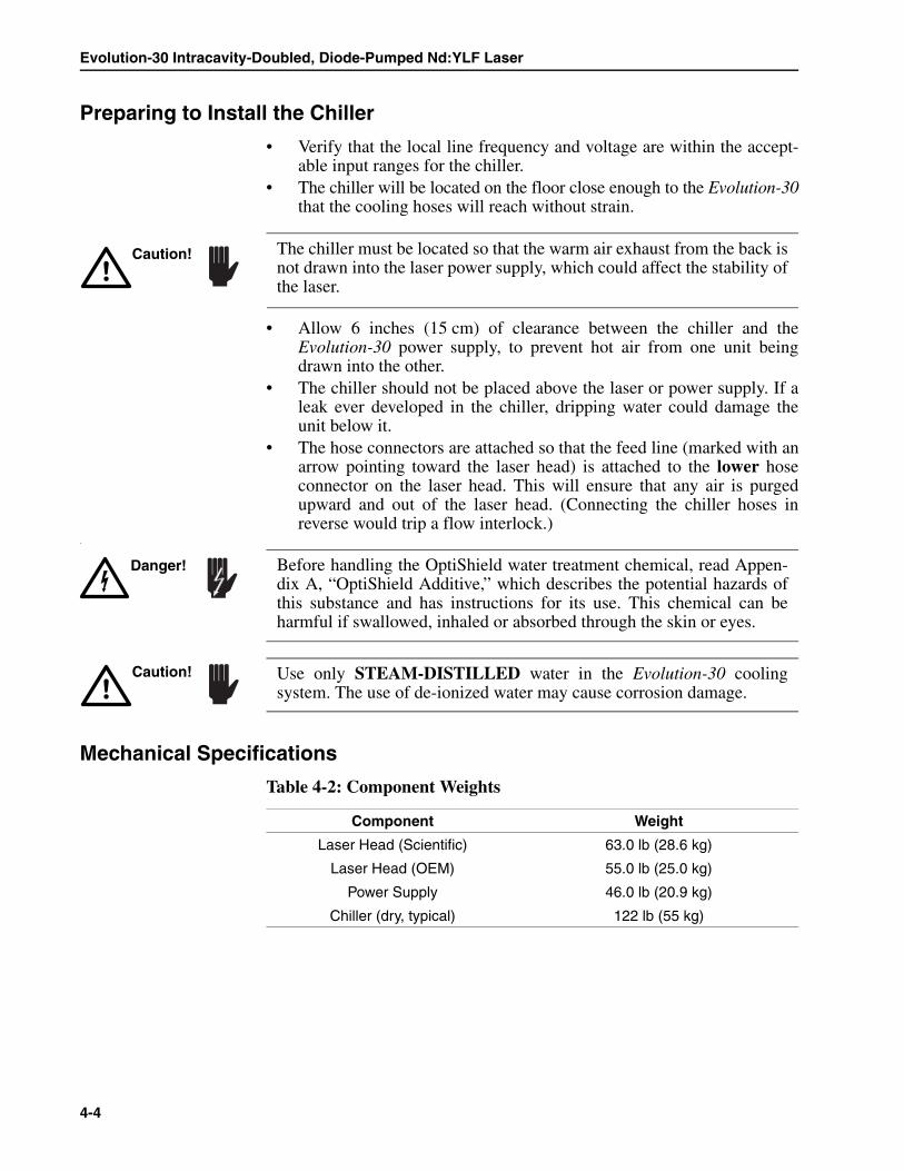
Evolution-30 Intracavity-Doubled, Diode-Pumped Nd:YLF Laser
4-4
Preparing to Install the Chiller
• Verify that the local line frequency and voltage are within the accept-able input ranges for the chiller.
• The chiller will be located on the floor close enough to the Evolution-30that the cooling hoses will reach without strain.
• Allow 6 inches (15 cm) of clearance between the chiller and theEvolution-30 power supply, to prevent hot air from one unit beingdrawn into the other.
• The chiller should not be placed above the laser or power supply. If aleak ever developed in the chiller, dripping water could damage theunit below it.
• The hose connectors are attached so that the feed line (marked with anarrow pointing toward the laser head) is attached to the lower hoseconnector on the laser head. This will ensure that any air is purgedupward and out of the laser head. (Connecting the chiller hoses inreverse would trip a flow interlock.)
.
Mechanical Specifications
Table 4-2: Component Weights
Component Weight
Laser Head (Scientific) 63.0 lb (28.6 kg)
Laser Head (OEM) 55.0 lb (25.0 kg)
Power Supply 46.0 lb (20.9 kg)
Chiller (dry, typical) 122 lb (55 kg)
The chiller must be located so that the warm air exhaust from the back isnot drawn into the laser power supply, which could affect the stability ofthe laser.
Caution!
Before handling the OptiShield water treatment chemical, read Appen-dix A, “OptiShield Additive,” which describes the potential hazards ofthis substance and has instructions for its use. This chemical can beharmful if swallowed, inhaled or absorbed through the skin or eyes.
Danger!
Use only STEAM-DISTILLED water in the Evolution-30 coolingsystem. The use of de-ionized water may cause corrosion damage.
Caution!
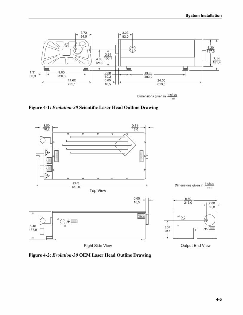
System Installation
4-5
Figure 4-1: Evolution-30 Scientific Laser Head Outline Drawing
Figure 4-2: Evolution-30 OEM Laser Head Outline Drawing
24.00610,0
0.6516,5
3.7294,5
11.62295,1
3.94100,14.88
124,0
3.2382,0
6.20157,5
7.14181,4
2.3860,3
9.00228,6
1.3133,3
19.00483,0
Dimensions given in inchesmm
24.3616,0
3.0076,2
0.5113,0
0.6516,5
5.43137,9
8.50216,0 2.00
50,8
3.5790,7
Output End View
Top View
Right Side View
808-
5326
VIS
IBLE
AN
D/O
R IN
VIS
IBLE
LA
SE
R R
AD
IAT
ION
WH
EN
OP
EN
AN
D IN
TE
RLO
CK
DE
FE
AT
ED
!A
VO
ID E
YE
OR
SK
IN E
XP
OS
UR
E T
O D
IRE
CT
OR
SC
AT
TE
RE
D R
AD
IAT
ION
.C
LAS
S IV
LA
SE
R R
AD
IAT
ION
VIS
IBLE
AN
D/O
R IN
VIS
IBLE
LAS
ER
RA
DIA
TIO
N W
HE
NO
PE
N A
ND
INT
ER
LOC
KD
EF
EA
TE
D!
AV
OID
EY
E O
R S
KIN
EX
PO
SU
RE
TO
DIR
EC
TO
R S
CA
TT
ER
ED
RA
DIA
TIO
N.
CLA
SS
1V LA
SE
R P
RO
DU
CT
808-7255
VIS
IBLE
AN
D/O
R IN
VIS
IBLE
LAS
ER
RA
DIA
TIO
N W
HE
NO
PE
N A
ND
INT
ER
LOC
KD
EF
EA
TE
D!
AV
OID
EY
E O
R S
KIN
EX
PO
SU
RE
TO
DIR
EC
TO
R S
CA
TT
ER
ED
RA
DIA
TIO
N.
CLA
SS
1V LA
SE
R P
RO
DU
CT
808-7255
808-5326
VIS
IBLE
AN
D/O
R IN
VIS
IBLE
LAS
ER
RA
DIA
TIO
NW
HE
N O
PE
N A
ND
INT
ER
LOC
K D
EF
EA
TE
D!
AV
OID
EY
E O
R S
KIN
EX
PO
SU
RE
TO
DIR
EC
TO
R S
CA
TT
ER
ED
RA
DIA
TIO
N.
CLA
SS
IV LA
SE
R R
AD
IAT
ION
AVOID EXPOSUREVISIBLE AND/ORINVISIBLE LASER
RADIATION IS EMITTEDFROM THIS APERTURE
808-
5276
MANUFACTURED:
MONTH
MODEL
YEAR
S/N
THIS LASER PRODUCT COMPLIESWITH 21 CFR 1040 AS APPLICABLE.
MADE IN U.S.A.
Spectra-Physics Lasers, Inc.1344 Terra Bella Avenue
Mountain View, California 94039
0420-7840
AVOID EXPOSUREVISIBLE AND/ORINVISIBLE LASER
RADIATION IS EMITTEDFROM THIS APERTURE
808-
5276
Dimensions given in inchesmm
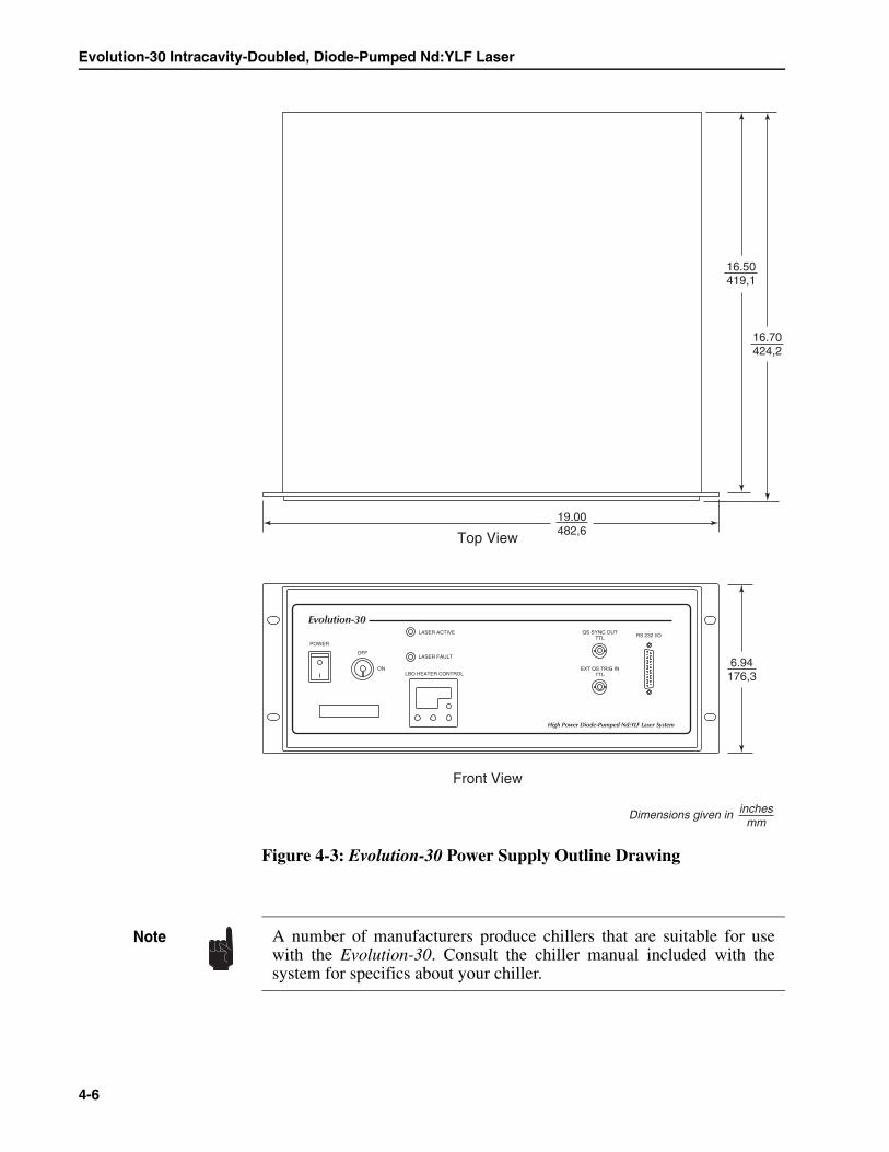
Evolution-30 Intracavity-Doubled, Diode-Pumped Nd:YLF Laser
4-6
Figure 4-3: Evolution-30 Power Supply Outline Drawing
POWER
OFF
ON
Evolution-30LASER ACTIVE
LASER FAULT
LBO HEATER CONTROL
RS 232 I/OQS SYNC OUT
TTL
EXT QS TRIG INTTL
High Power Diode-Pumped Nd:YLF Laser System
19.00482,6
16.70424,2
6.94176,3
16.50419,1
Top View
Front View
Dimensions given in inchesmm
A number of manufacturers produce chillers that are suitable for usewith the Evolution-30. Consult the chiller manual included with thesystem for specifics about your chiller.
Note

5-1
Chapter 5 System Operation
Overview
Routine operation of the Evolution-30 is via the “Evolution-30 Control”software running on the host computer. It controls both the laser head andthe power supply. Familiarize yourself with the operation of the power sup-ply module and the control software described below before proceeding tothe “Start-Up Procedure” later in this chapter.
Electrical Current Settings
The Evolution-30 laser comes with a set of performance data that lists thefactory-measured output power as a function of diode laser current at thenominal Q-switch repetition rate that was specified when the laser wasordered. Your authorized service representative will verify these measure-ments when the laser is installed.
It is useful to establish at least three nominal current settings: Low,Medium and High (for example, 15 A, 20 A and 25 A) that produce, forexample, 6 W, 15 W, and 20 W for a standard 1 kHz system. This sectionwill refer to these settings as Low, Medium and High. If the Evolution-30 isnot operated at its maximum specified output power, scale these settingsappropriately when following the procedures in this chapter or whenfollowing any troubleshooting procedures.
After several hundred hours of operation the diode laser output power willdecrease slightly. (This is a normal “burn-in” period.) The maximum possi-ble current is set at the factory to ensure that the laser will meet its specifiedpower for thousands of hours of operation.
Safety glasses for all lasing wavelengths must be worn at all times whenoperating this laser system. Consult your laser safety officer to selectappropriate safety glasses. You MUST read “Chapter 2, Laser Safety.”
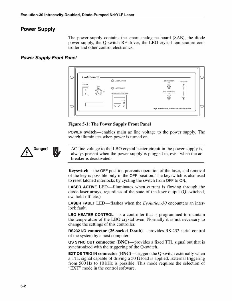
Evolution-30 Intracavity-Doubled, Diode-Pumped Nd:YLF Laser
5-2
Power Supply
The power supply contains the smart analog pc board (SAB), the diodepower supply, the Q-switch RF driver, the LBO crystal temperature con-troller and other control electronics.
Power Supply Front Panel
Figure 5-1: The Power Supply Front Panel
POWER switch—enables main ac line voltage to the power supply. Theswitch illuminates when power is turned on.
Keyswitch—the OFF position prevents operation of the laser, and removalof the key is possible only in the OFF position. The keyswitch is also usedto reset latched interlocks by cycling the switch from OFF to ON.
LASER ACTIVE LED—illuminates when current is flowing through thediode laser arrays, regardless of the state of the laser output (Q-switched,cw, hold-off, etc.)
LASER FAULT LED—flashes when the Evolution-30 encounters an inter-lock fault.
LBO HEATER CONTROL—is a controller that is programmed to maintainthe temperature of the LBO crystal oven. Normally it is not necessary tochange the settings of this controller.
RS232 I/O connector (25-socket D-sub)— provides RS-232 serial controlof the system by a host computer.
QS SYNC OUT connector (BNC)—provides a fixed TTL signal out that issynchronized with the triggering of the Q-switch.
EXT QS TRIG IN connector (BNC)—triggers the Q-switch externally whena TTL signal capable of driving a 50 Ω load is applied. External triggeringfrom 500 Hz to 10 kHz is possible. This mode requires the selection of“EXT” mode in the control software.
POWER
OFF
ON
Evolution-30LASER ACTIVE
LASER FAULT
LBO HEATER CONTROL
RS 232 I/OQS SYNC OUT
TTL
EXT QS TRIG INTTL
High Power Diode-Pumped Nd:YLF Laser System
AC line voltage to the LBO crystal heater circuit in the power supply isalways present when the power supply is plugged in, even when the acbreaker is deactivated.
Danger!

System Operation
5-3
Power Supply Rear Panel
Figure 5-2: The Power Supply Rear Panel
AC IN connector —provides connection for the main input power source:either 110 Vac ± 10%, 50/60 Hz, or 220 Vac ± 10%, 50 Hz. Use the fusesize listed in Table 5-1.
RF OUT connectors (BNC)—output 30 watts each, 100–150 Vrms sine waveat 27.11 MHz into a 50 Ω load to drive the two Evolution-30 Q-switches.DO NOT connect these signals to anything other than the BNC connectorspresent in the Evolution-30 laser head umbilical.
26-pin connector (unlabeled)—supplies interlock and control signals tothe laser head. Connects to the 26-pin umbilical cable.
4-pin connector (unlabeled)—supplies current to the diode laser arrays inthe laser head. Connects to the 4-pin umbilical cable.
INTERLOCK connector (3-pin)—is used to interlock the laser via a con-trolled access point, such as a laboratory door. Pins J1 and J2 (shown in Fig-ure 2-2) must be shorted in order to enable laser operation.
CURRENT MONITOR connector (BNC)—output that indicates the amountof current flowing through the diode arrays. The scale is 10 amps/volt.
Table 5-1: Evolution-30 Fuse Specifications
Line Voltage/Vac F1/F2: 3AG Slow Blow
200–240100–120
10 A/10 A15 A/15 A
QS Sync OutTTL
CurrentMonitor
Interlock
RF OutRF Out
The power supply for the Evolution-30 is similar in appearance to thoseused by other models of the Evolution laser family, but the powersupplies are NOT interchangeable.
Note
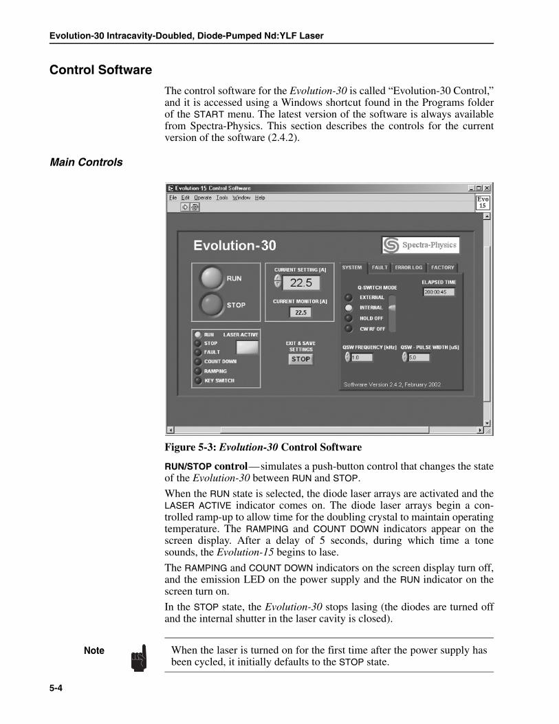
Evolution-30 Intracavity-Doubled, Diode-Pumped Nd:YLF Laser
5-4
Control Software
The control software for the Evolution-30 is called “Evolution-30 Control,”and it is accessed using a Windows shortcut found in the Programs folderof the START menu. The latest version of the software is always availablefrom Spectra-Physics. This section describes the controls for the currentversion of the software (2.4.2).
Main Controls
Figure 5-3: Evolution-30 Control Software
RUN/STOP control—simulates a push-button control that changes the stateof the Evolution-30 between RUN and STOP.
When the RUN state is selected, the diode laser arrays are activated and theLASER ACTIVE indicator comes on. The diode laser arrays begin a con-trolled ramp-up to allow time for the doubling crystal to maintain operatingtemperature. The RAMPING and COUNT DOWN indicators appear on thescreen display. After a delay of 5 seconds, during which time a tonesounds, the Evolution-15 begins to lase.
The RAMPING and COUNT DOWN indicators on the screen display turn off,and the emission LED on the power supply and the RUN indicator on thescreen turn on.
In the STOP state, the Evolution-30 stops lasing (the diodes are turned offand the internal shutter in the laser cavity is closed).
When the laser is turned on for the first time after the power supply hasbeen cycled, it initially defaults to the STOP state.
Note
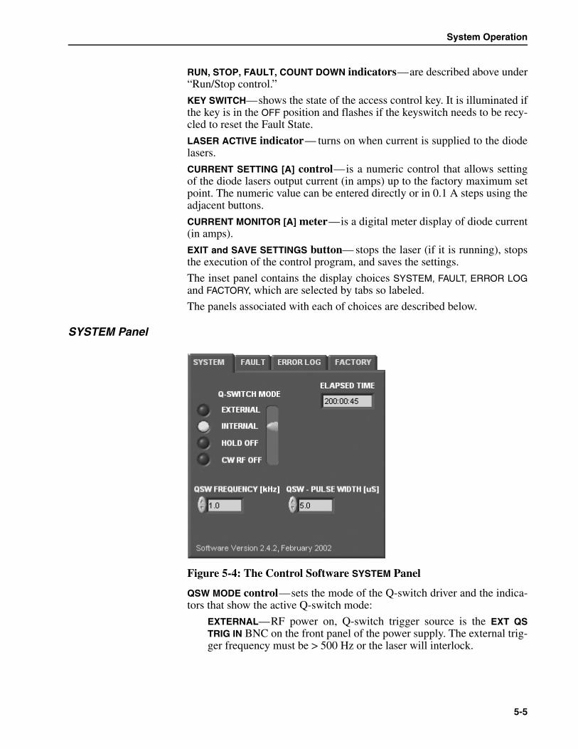
System Operation
5-5
RUN, STOP, FAULT, COUNT DOWN indicators—are described above under“Run/Stop control.”
KEY SWITCH—shows the state of the access control key. It is illuminated ifthe key is in the OFF position and flashes if the keyswitch needs to be recy-cled to reset the Fault State.
LASER ACTIVE indicator— turns on when current is supplied to the diodelasers.
CURRENT SETTING [A] control—is a numeric control that allows settingof the diode lasers output current (in amps) up to the factory maximum setpoint. The numeric value can be entered directly or in 0.1 A steps using theadjacent buttons.
CURRENT MONITOR [A] meter—is a digital meter display of diode current(in amps).
EXIT and SAVE SETTINGS button— stops the laser (if it is running), stopsthe execution of the control program, and saves the settings.
The inset panel contains the display choices SYSTEM, FAULT, ERROR LOGand FACTORY, which are selected by tabs so labeled.
The panels associated with each of choices are described below.
SYSTEM Panel
Figure 5-4: The Control Software SYSTEM Panel
QSW MODE control—sets the mode of the Q-switch driver and the indica-tors that show the active Q-switch mode:
EXTERNAL—RF power on, Q-switch trigger source is the EXT QSTRIG IN BNC on the front panel of the power supply. The external trig-ger frequency must be > 500 Hz or the laser will interlock.

Evolution-30 Intracavity-Doubled, Diode-Pumped Nd:YLF Laser
5-6
INTERNAL—RF power on, Q-switch trigger source is the internalclock on the SAB, repetition rate set by the software QSW Frequencycontrol.
HOLD OFF—RF power on, no Q-switch triggers. It is used to checkalignment of the Q-switches during servicing of the laser.
CW RF OFF—(Continuous wave) RF power off. It is used for settingand checking laser cavity alignment during servicing of the laser.
QSW FREQUENCY [kHz] control—sets the frequency of the internal Q-switchtrigger source.
QSW PULSE WIDTH [µs] control—sets the width of the internal triggerpulse to the Q-switch driver.
ELAPSED TIME display—shows the cumulative hours and minutes of laseroperation.
FAULT Panel
Figure 5-5: Control Software FAULT Panel
COVER/USER LED—turns on when any of the micro-switches on the laserhead are not engaged or when the user interlock is open. Verify the coversare closed or that the interlocks are defeated on the laser head, and that thedoor interlock switch is closed or interlock defeated, then cycle the key-switch to clear the fault.
Changing from non-Q-switching modes (CW and HOLD OFF) to lasingmodes (INTERNAL and EXTERNAL) while the laser is running will causethe laser to switch to Stop mode. When this happens, restart the laser bysimply switching to Run mode.
Caution!

System Operation
5-7
FLOW LED—turns on when chiller water flow is less than 2.0 GPM. Ver-ify the chiller is functioning properly and that water pressure and reservoirlevel are correct, and that the water hoses are not kinked to ensure adequateflow, then cycle keyswitch to clear the fault.
LBO TEMP LED—turns on when the LBO temperature is outside a presetrange around the factory set point. Allow the temperature to return to spec-ified temperature range before turning on the system again.
QSW LOW FREQ LED—turns on when the QSW MODE is set to EXTER-NAL and the external source of triggering drops below 500 Hz. Ensure thatthe source of external Q-switch triggering is producing TTL pulses at500 Hz or higher.
QSW VSWR LED—turns on when either or both of the QSW RF connectorson the back of the power supply are disconnected.
QSW TEMP LED—turns on when the thermal sensor in either AOMexceeds the safe operating temperature for that device. Verify the chiller isfunctioning properly and that water pressure and reservoir level are correct,and that the water hoses are not kinked to ensure adequate flow, then cyclekeyswitch to clear the fault.
COMM ERROR LED—turns on when communications are interruptedbetween the computer and the power supply. Check the serial cable connec-tions and verify the power supply is turned on. Exit the Control Software,cycle ac power on the power supply, then restart the Control Software toclear the fault.
DRIVER TEMP LED—turns on when the temperature of the diode driver(FET) heat sink becomes overheated due to inadequate airflow to thedriver, or to a shorted or over-current condition. Verify airflow in the powersupply is adequate and allow the system to run without lasing for at least 10minutes to cool it down, then restart the laser.
DIODE TEMP LED—turns on when the temperature sensor mounted in thelaser pump chamber exceeds the safe operating temperature. Turn off thepower supply and allow the chiller to run for 10 minutes to cool it down,verify proper chiller temperature, then restart the laser, running it at a lowerdiode laser drive current.
OVER VOLTAGE LED—turns on when the voltage required to supply therequested current to the diodes exceeds the factory-set limit. Check thediode umbilical connection and cycle power on the power supply to clearthe fault.
OVER CURRENT LED—turns on when the current requested to drive thediode array exceeds the factory-set limit. Lower the current drive setting,then cycle power on the power supply to clear the fault.
OVER POWER LED—turns on when the internal drive FET exceeds afactory-set power limit. Reduce the diode drive current, then cycle thepower on the power supply to clear the fault.
PROT FAULT LED— turns on when the internal drive FET protection cir-cuit is activated. This is a serious internal driver failure that requires repair.
Do not operate the Evolution-30 if a PROT FAULT error occurs!Warning!
Evolution-30 Intracavity-Doubled, Diode-Pumped Nd:YLF Laser
5-8
CHECKSUM ERROR LED—turns on when a garbled communicationsmessage is detected between the Control Software and the Evolution-30.Normally these can be ignored, but if they occur frequently, check the RS-232 cable connections.
ERROR LOG Panel
This window displays all the fault conditions, fault corrections and theirtime stamps.
FACTORY Panel
The controls available under this tab are reserved for use in the factory. Donot use them!
Start-Up Procedure
Follow these procedures when starting and operating the Evolution-30 lasersystem.
1. Verify the power supply chassis is plugged in and the umbilical cablesare connected properly.
2, Verify that the LBO Heater Control temperature is at the properfactory-set temperature.
3. Turn on the chiller.
4. Verify the control cable is connected between the computer and thepower supply.
5. Boot the control computer and log in (if necessary).
6. Turn on the power supply power switch.
7. Insert the key in the keyswitch and turn it to the ON position.
8. Start the Evolution-30 control software.
After the Control Software begins communicating with the Evolution-30 and all interlocks are closed, the STOP indicator on the ControlSoftware screen will turn on, indicating that the laser can be started.
If the FAULT indicator on the power supply flashes, or the FAULT indi-cator on the Control Software screen is on, refer to the Troubleshoot-ing Guide in Chapter 7 for help in clearing the interlock faults.
9. Set the CURRENT SETTING on the Control Software screen to thenominal Low setting.
The following procedures will result in laser emission from theEvolution-30 output port. Ensure that all persons in the room are wearingadequate eye protection. Also ensure that the anticipated beam is safelyterminated into a high power beam block or power meter.
System Operation
5-9
10. If the Evolution-30 is to be internally Q-switched, set the QSWFREQUENCY control to the proper repetition rate (e.g., 1.0 kHz), andset the QSW MODE switch to INTERNAL.
11. If the Evolution-30 is to be externally Q-switched, attach a TTL-levelsignal (at least 2.5 µs duration) at the proper frequency to the EXT QSTRIG IN connector on the front panel of the power supply, and set theQSW MODE to EXTERNAL. Q-switch operation is synchronized to therising edge of the input pulse.
12. Rotate the output shutter on the front or remove the plug from the sideof the Evolution-30 (depending on which port is being used) to theopen position. Verify laser output will be directed into an appropriatetermination (e.g., beam dump, power meter, Spitfire, etc.).
13. Slide the Laser State control on the Control Software screen to theRUN position. The LASER ACTIVE LED on the power supply will turnon, as will the LASER ACTIVE indicator on the Control Softwarescreen. The CURRENT MONITOR will display the set-point level inapproximately 5 seconds.
Please note that it takes the chiller about 15 minutes to stabilize thetemperature of the laser head cold plate and, thus, the output of thelaser. If the laser is used frequently, leaving the chiller on betweenperiods of use will eliminate or greatly reduce this stabilization period.If the laser is used infrequently, turn off the chiller between periods ofuse.
14. Measure output power with a power meter capable of measuring30 Watts minimum. Within several minutes, the 527 nm power shouldbe the same as or close to the power that was previously measured atthe Low current setting.
15. Manually increase the current setting at a rate of no more than 1 ampper second until the Medium-current setting is reached. Monitor thepower continuously as you make this adjustment to ensure that thepower increases monotonically with the current. If output power islow, wait 10 minutes for the laser temperature to stabilize. Once thepower reaches the Medium-current setting, increase the current to theHigh setting and verify the power again. If the beam does not reachoperating power, it may be necessary to optimize the lasing output asdescribed in Chapter 6, “Maintenance.”
Your Evolution-30 was optimized at a user-requested specific Q-switchrepetition rate. Operating the laser at a significantly different rate mayresult in decreased performance or damage to the instrument.
Caution!

Evolution-30 Intracavity-Doubled, Diode-Pumped Nd:YLF Laser
5-10
System Shutdown
1. Click the STOP button on the Control Software screen. The shutter willclose and the diodes will shut off immediately.
2. Close the Control Software window.
3. Turn the keyswitch to OFF and remove the key from the keyswitch.
4. Turn off the main power switch.
5. Turn off the chiller if the system is used infrequently.
Long Term Shutdown
If the Evolution-30 will be disconnected from line voltage for an extendedperiod of time (greater than a few minutes), follow this procedure to slowlyramp down the LBO crystal temperature to room temperature to avoidthermal shock to the crystal.
1. On the LBO Heater Control module on the front panel of the powersupply, note the factory setting, then press and hold the down arrowbutton (lower right) until the temperature setting is 75°F or cooler.
2. Allow the crystal temperature to ramp down until it reaches 75°F.
3. Turn off the Evolution-30 power supply and disconnect the powercord.
4. To return the Evolution-30 to normal operation, plug in the powersupply and reset the temperature to the factory-set temperature notedduring shut-down. When the LBO crystal reaches the new set point,the laser can be operated normally.

6-1
Chapter 6 Maintenance
The Evolution-30 has been designed for minimal maintenance. The routineprocedures described in this chapter are recommended to keep the systemin good working condition. For further information, contact your Spectra-Physics service representative.
Lasing Optimization
Cavity Mirror Adjustments
All of the optical mounts in the Evolution-30 are securely fastened to therigid base plate of the laser head. Nevertheless, the mirrors may becomeslightly misaligned due to changes in room temperature, bumps or otherstresses on the laser head. If this happens, the end mirrors of the lasercavity may require adjustment.
Use the following procedure to optimize the cavity mirrors:
Materials required:
• Laser safety goggles• Infrared viewer or card• Two 1/8-inch ball-tipped Allen wrenches• Calibrated power meter capable of measuring at least 30 watts
Improper adjustment of the Evolution-30 laser can result in damage tothe laser rod or LBO crystal. Do not attempt to adjust the Evolution-30mirrors until you have read this section. If you are uncertain about thisprocedure, contact your Service representative for assistance.
Protective eyewear MUST be worn for protection from all wavelengthsemitted by the Evolution-30. Refer to Chapter 2, “Laser Safety,” in thismanual.
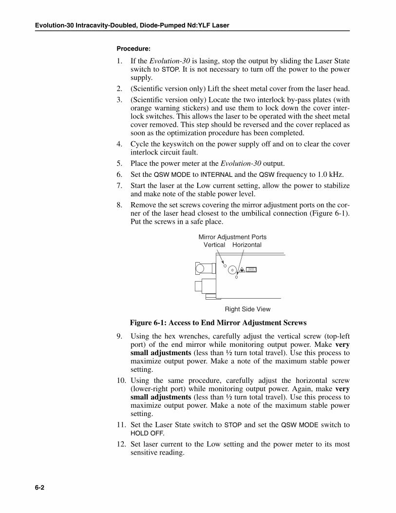
Evolution-30 Intracavity-Doubled, Diode-Pumped Nd:YLF Laser
6-2
Procedure:
1. If the Evolution-30 is lasing, stop the output by sliding the Laser Stateswitch to STOP. It is not necessary to turn off the power to the powersupply.
2. (Scientific version only) Lift the sheet metal cover from the laser head.
3. (Scientific version only) Locate the two interlock by-pass plates (withorange warning stickers) and use them to lock down the cover inter-lock switches. This allows the laser to be operated with the sheet metalcover removed. This step should be reversed and the cover replaced assoon as the optimization procedure has been completed.
4. Cycle the keyswitch on the power supply off and on to clear the coverinterlock circuit fault.
5. Place the power meter at the Evolution-30 output.
6. Set the QSW MODE to INTERNAL and the QSW frequency to 1.0 kHz.
7. Start the laser at the Low current setting, allow the power to stabilizeand make note of the stable power level.
8. Remove the set screws covering the mirror adjustment ports on the cor-ner of the laser head closest to the umbilical connection (Figure 6-1).Put the screws in a safe place.
Figure 6-1: Access to End Mirror Adjustment Screws
9. Using the hex wrenches, carefully adjust the vertical screw (top-leftport) of the end mirror while monitoring output power. Make verysmall adjustments (less than ½ turn total travel). Use this process tomaximize output power. Make a note of the maximum stable powersetting.
10. Using the same procedure, carefully adjust the horizontal screw(lower-right port) while monitoring output power. Again, make verysmall adjustments (less than ½ turn total travel). Use this process tomaximize output power. Make a note of the maximum stable powersetting.
11. Set the Laser State switch to STOP and set the QSW MODE switch toHOLD OFF.
12. Set laser current to the Low setting and the power meter to its mostsensitive reading.
Right Side View
Mirror Adjustment PortsVertical Horizontal
AVOID EXPOSUREVISIBLE AND/ORINVISIBLE LASER
RADIATION IS EMITTEDFROM THIS APERTURE
808-
5276
Maintenance
6-3
13. Click on RUN on the screen display to start the Evolution-30, then usean infrared viewer or card to verify there is no visible or infraredoutput from the laser. If any is detected, turn off the laser and contactSpectra-Physics for assistance.
14. Slowly turn up the current to the High setting while monitoring laserpower. Power should remain at zero as the current ramps all the wayup to the maximum current setting. As in the previous step, verify thatthere is no visible or infrared output, and if any is detected, turn offthe laser and contact Spectra-Physics for assistance.
15. Click on STOP on the screen display, then slide the QSW MODE selec-tor to INTERNAL, set laser current to the Low setting and restart thelaser with the Laser State switch. Note the output power level.
16. Fine-tune the vertical and horizontal adjustment screws on the mirrorto return output power to the maximum value previously recorded.
17. Once output power is optimized, slowly turn up the power control tothe Medium current setting, and then to the High setting while moni-toring the power meter. When the current reaches the High setting,allow the laser to stabilize, and note the stable power level.
18. If, at any time, laser power starts to fluctuate rapidly, turn off the laserand contact Spectra-Physics for assistance.
If this procedure does not cause the Evolution-30 to meet its specifiedpower, it may be necessary to optimize the LBO crystal temperature (seethe procedure below).
LBO Crystal Temperature Optimization
Depending on environmental conditions, the optimum LBO crystal temper-ature for efficient intracavity doubling may vary slightly from the factory setpoint. LBO crystal temperature can be varied plus or minus 1.5°F aroundthe factory-set temperature to compensate for environmental effects.
If, at any time, while optimizing the LBO temperature at the Mediumcurrent setting output power drops by more than 20%, turn off the laserimmediately. (Optical damage could occur if the LBO temperature isseverely detuned, resulting in insufficient second harmonic light beingcoupled out of the optical resonator.) Perform the optimization proce-dure described below. If you are uncertain about this procedure, contactyour authorized Spectra-Physics service representative for assistance.
If the temperature of the LBO heater deviates from the factory setting bymore than 1.5°F, an LBO TEMP fault will occur. In this event, return thesetting to the factory setting and restart the optimization procedure, butin the opposite temperature direction. If you still believe the optimumLBO temperature setting is more than 1.5°F away from the factorysetting, contact your authorized Spectra-Physics service representative.
Caution!
Evolution-30 Intracavity-Doubled, Diode-Pumped Nd:YLF Laser
6-4
To optimize the LBO temperature:
1. Note the present temperature setting as displayed on the LBO temper-ature controller screen.
2. Set the laser current to the Medium setting, turn on the laser and allowit to stabilize for 10 minutes. Note power output with a power meter.
3. While monitoring output power, use the up/down arrows on the LBOHEATER CONTROLLER to change the temperature set point by 0.5°F.After the temperature stabilizes at the new setting, again note outputpower. If power has increased, change the temperature by another0.5°F in the same direction. If it decreased, change the temperature by0.5°F in the opposite direction. Repeat this until the power is maxi-mized.
4. When output power has been maximized, make a note of the tempera-ture setting for future reference.
Cleaning the Optics
The Evolution-30 is sealed against dust and debris, but depending on thecleanliness of the environment, it is possible that some dust may get intothe laser head. When this happens, clean the optics.
Materials required:
• Safety goggles• Clean plastic gloves or finger cots• Lens cleaning tissue (Kodak brand or equivalent quality)• Reagent-grade methanol or acetone• Eye dropper• Hemostat (surgical pliers)• English hex-wrench set• Bright lamp or flashlight
Cleaning the optics will require opening the optical cavity. This proce-dure should not be performed without prior approval of your authorizedSpectra-Physics service representative. Unauthorized opening of theseal will void your warranty and may damage your laser.
Cleaning the optics may result in misalignment of the laser cavity. Aftercleaning, the cavity should be realigned using the procedure earlier inthis chapter.
The Evolution-30 is assembled with chemically-cleaned parts. Toprevent contamination, wear plastic gloves or finger cots while workinginside the housing.

Maintenance
6-5
Accessing the Evolution-30 optics
1. Turn off the Evolution-30 power supply.
2. (Scientific version only) Remove the external sheet metal cover.
3. Remove the screws holding the machined metal cover in place and putthe screws in a safe place.
4. Remove the machined cover and place it on a clean surface.
Mirrors
Mirrors should be carefully cleaned with soft optical tissue and reagent-grade methanol or acetone.
1. Fold a piece of lens tissue repeatedly to form a pad approximately1 cm wide.
2. Hold the pad with the hemostat so that about 3 mm of the folded edgeprotrudes from the hemostat.
3. Saturate the pad with methanol or acetone and shake to remove excesssolvent.
4. Reach slightly below the center of the optic and wipe the surface of theoptic toward the outside in one motion. Be careful that the hemostatdoes not touch the optic or the surface will be damaged.
5. If cleaning the intracavity dichroic mirror, repeat this operation using aclean tissue on the other optical surface.
Q-Switch
The Q-switch can be difficult to clean; attempt to clean it only if dust ordebris are clearly visible. When cleaning the Q-switch crystal faces, it isnecessary to remove the U-shaped cover around the Q-switch in order togain unobstructed access to the quartz faces. Do not touch the transducerconnections.
The LBO crystal is kept above 320°F (160°C). Prolonged contact withthe LBO crystal housing can burn skin, melt plastic and ignite flam-mable material.
Danger!
Never attempt to clean the LBO crystal or the Nd:YLF laser rod in thissystem. Optical damage will occur and warranty will be voided if eitherof these two optics have been tampered with. If you feel that opticaldamage has occurred or cleaning of these optics is necessary, contactyour authorized Spectra-Physics service representative.
Evolution-30 Intracavity-Doubled, Diode-Pumped Nd:YLF Laser
6-6
Routine Maintenance—Cooling Water
To prevent metal corrosion and growth of algae in the Evolution-30 closed-loop cooling water system, OptiShield® corrosion inhibitor is recom-mended. This chemical treatment prevents galvanic corrosion from dissim-ilar metals, prevents oxidation of ferrous metals and acts as an effectivealgaecide. The first application of OptiShield is normally performed at thefactory and a similar application will be repeated during system installa-tion. Thereafter, for most Evolution-30 systems the OptiShield solutionshould be changed once a year according to the following procedure.
Periodic changing of solution:
1. Drain the old fluid from system.
2. The chiller has a 2-gallon capacity. Refill the reservoir with 2 pints ofOptiShield and the remaining volume (14 pints) with steam-distilledwater.
3. Turn on the chiller and verify that water is flowing (e.g., the flow inter-lock has not been activated). Inspect for leaks at the hose connectionsbetween the laser head and chiller.
4. Turn off the chiller.
OptiShield is a registered trademark of Opti Temp, Inc.
Before handling the OptiShield water treatment chemical, read theMaterial Safety Data Sheet included in Appendix A. This sheetdescribes the potential hazards of this material and provides handlingprecautions associated with it. This chemical can be harmful ifswallowed, inhaled or absorbed through the skin or eyes.
Danger!
Use only STEAM-DISTILLED water in the Evolution-30 coolingsystem. The use of de-ionized water may cause corrosion damage.
Caution!
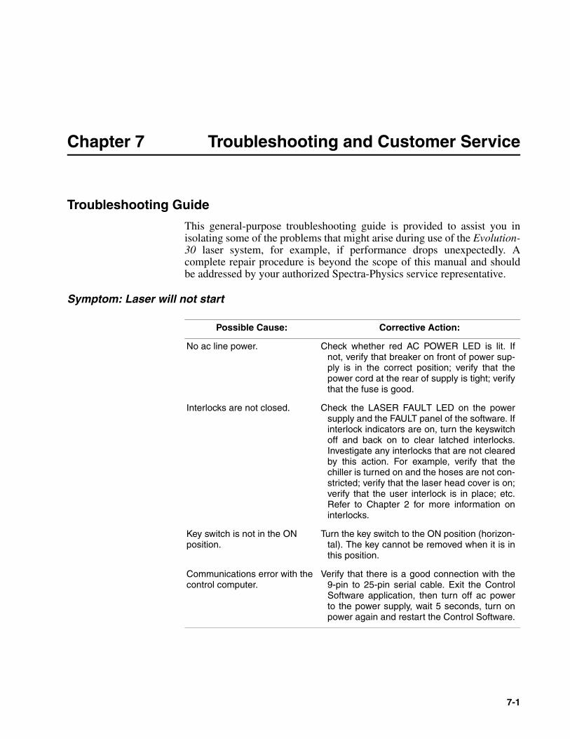
7-1
Chapter 7 Troubleshooting and Customer Service
Troubleshooting Guide
This general-purpose troubleshooting guide is provided to assist you inisolating some of the problems that might arise during use of the Evolution-30 laser system, for example, if performance drops unexpectedly. Acomplete repair procedure is beyond the scope of this manual and shouldbe addressed by your authorized Spectra-Physics service representative.
Symptom: Laser will not start
Possible Cause: Corrective Action:
No ac line power. Check whether red AC POWER LED is lit. Ifnot, verify that breaker on front of power sup-ply is in the correct position; verify that thepower cord at the rear of supply is tight; verifythat the fuse is good.
Interlocks are not closed. Check the LASER FAULT LED on the powersupply and the FAULT panel of the software. Ifinterlock indicators are on, turn the keyswitchoff and back on to clear latched interlocks.Investigate any interlocks that are not clearedby this action. For example, verify that thechiller is turned on and the hoses are not con-stricted; verify that the laser head cover is on;verify that the user interlock is in place; etc.Refer to Chapter 2 for more information oninterlocks.
Key switch is not in the ON position.
Turn the key switch to the ON position (horizon-tal). The key cannot be removed when it is inthis position.
Communications error with the control computer.
Verify that there is a good connection with the9-pin to 25-pin serial cable. Exit the ControlSoftware application, then turn off ac powerto the power supply, wait 5 seconds, turn onpower again and restart the Control Software.
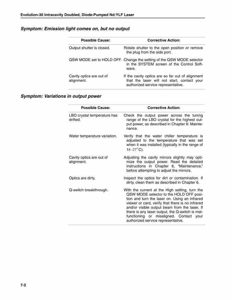
Evolution-30 Intracavity Doubled, Diode-Pumped Nd:YLF Laser
7-2
Symptom: Emission light comes on, but no output
Symptom: Variations in output power
Possible Cause: Corrective Action:
Output shutter is closed. Rotate shutter to the open position or removethe plug from the side port.
QSW MODE set to HOLD OFF. Change the setting of the QSW MODE selectorin the SYSTEM screen of the Control Soft-ware.
Cavity optics are out of alignment.
If the cavity optics are so far out of alignmentthat the laser will not start, contact yourauthorized service representative.
Possible Cause: Corrective Action:
LBO crystal temperature has drifted.
Check the output power across the tuningrange of the LBO crystal for the highest out-put power, as described in Chapter 6: Mainte-nance.
Water temperature variation. Verify that the water chiller temperature isadjusted to the temperature that was setwhen it was installed (typically in the range of18–27°C).
Cavity optics are out of alignment.
Adjusting the cavity mirrors slightly may opti-mize the output power. Read the detailedinstructions in Chapter 6, “Maintenance,”before attempting to adjust the mirrors.
Optics are dirty. Inspect the optics for dirt or contamination. Ifdirty, clean them as described in Chapter 6.
Q-switch breakthrough. With the current at the High setting, turn theQSW MODE selector to the HOLD OFF posi-tion and turn the laser on. Using an infraredviewer or card, verify that there is no infraredand/or visible output beam from the laser. Ifthere is any laser output, the Q-switch is mal-functioning or misaligned. Contact yourauthorized service representative.
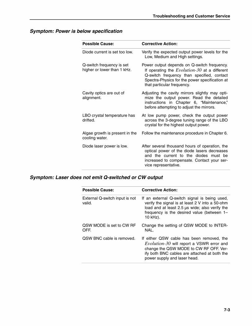
Troubleshooting and Customer Service
7-3
Symptom: Power is below specification
Symptom: Laser does not emit Q-switched or CW output
Possible Cause: Corrective Action:
Diode current is set too low. Verify the expected output power levels for theLow, Medium and High settings.
Q-switch frequency is set higher or lower than 1 kHz.
Power output depends on Q-switch frequency.If operating the Evolution-30 at a differentQ-switch frequency than specified, contactSpectra-Physics for the power specification atthat particular frequency.
Cavity optics are out of alignment.
Adjusting the cavity mirrors slightly may opti-mize the output power. Read the detailedinstructions in Chapter 6, “Maintenance,”before attempting to adjust the mirrors.
LBO crystal temperature has drifted.
At low pump power, check the output poweracross the 3-degree tuning range of the LBOcrystal for the highest output power.
Algae growth is present in the cooling water.
Follow the maintenance procedure in Chapter 6.
Diode laser power is low. After several thousand hours of operation, theoptical power of the diode lasers decreasesand the current to the diodes must beincreased to compensate. Contact your ser-vice representative.
Possible Cause: Corrective Action:
External Q-switch input is not valid.
If an external Q-switch signal is being used,verify the signal is at least 2 V into a 50-ohmload and at least 2.5 µs wide; also verify thefrequency is the desired value (between 1–10 kHz).
QSW MODE is set to CW RF OFF.
Change the setting of QSW MODE to INTER-NAL.
QSW BNC cable is removed. If either QSW cable has been removed, theEvolution-30 will report a VSWR error andchange the QSW MODE to CW RF OFF. Ver-ify both BNC cables are attached at both thepower supply and laser head.
Evolution-30 Intracavity Doubled, Diode-Pumped Nd:YLF Laser
7-4
Customer Service
At Spectra-Physics we take pride in the durability of our products. Weplace considerable emphasis on controlled manufacturing methods andquality control. Nevertheless, even the finest precision instruments needoccasional service.
Warranty
This warranty supplements the warranty contained in the specific salesorder. In the event of a conflict between documents, the terms and condi-tions of the sales order shall prevail.
The Evolution-30 is protected by a twelve-month warranty. All mechanicaland optical parts and assemblies are unconditionally warranted to be free ofdefects in workmanship and material for the warranty period. At its elec-tion, Spectra-Physics will repair or replace without charge components thatprove defective during the warranty period. The obligation of Spectra-Physics is limited to repair covered under the warranty return proceduredescribed below. Equipment repaired or replaced is warranted only for theremaining original warranty period.
This warranty is in lieu of all other warranties, implied or expressed, anddoes not cover incidental or consequential loss.
Spectra-Physics will provide at its expense all parts and labor and one-wayreturn shipping of the defective part or instrument (if required).
This warranty does not apply to any instrument or component not manufac-tured by Spectra-Physics. When products manufactured by others areincluded in Spectra-Physics equipment, the original manufacturer's war-ranty is extended to Spectra-Physics customers. When products manufac-tured by others are used in conjunction with Spectra-Physics equipment,this warranty is extended only to the equipment manufactured by Spectra-Physics.
This warranty does not apply to equipment or components that, upon inspec-tion by Spectra-Physics, discloses to be defective or unworkable because ofabuse, mishandling, misuse, alteration, negligence, improper installation,damage in transit, or other causes beyond the control of Spectra-Physics.
Return of the Instrument for Repair
Contact your nearest Spectra-Physics field sales office, service center orlocal distributor for shipping instructions or for an on-site service appoint-ment. You are responsible for one-way shipment of the defective part orinstrument to Spectra-Physics.
We encourage you to use the original shipping boxes. If the original boxeshave been destroyed or lost, we recommend that you order new ones. Wewill return instruments only in Spectra-Physics containers.
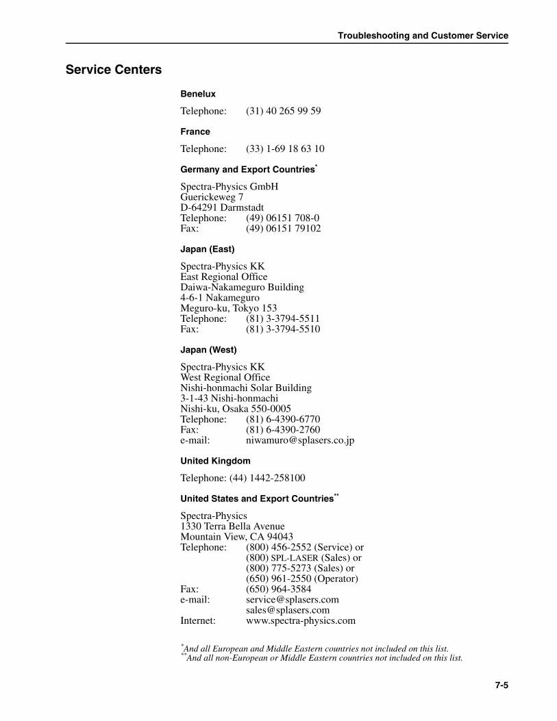
Troubleshooting and Customer Service
7-5
Service Centers
Benelux
Telephone: (31) 40 265 99 59
France
Telephone: (33) 1-69 18 63 10
Germany and Export Countries*
Spectra-Physics GmbHGuerickeweg 7D-64291 DarmstadtTelephone: (49) 06151 708-0Fax: (49) 06151 79102
Japan (East)
Spectra-Physics KKEast Regional OfficeDaiwa-Nakameguro Building4-6-1 NakameguroMeguro-ku, Tokyo 153Telephone: (81) 3-3794-5511Fax: (81) 3-3794-5510
Japan (West)
Spectra-Physics KKWest Regional OfficeNishi-honmachi Solar Building3-1-43 Nishi-honmachiNishi-ku, Osaka 550-0005Telephone: (81) 6-4390-6770Fax: (81) 6-4390-2760e-mail: [email protected]
United Kingdom
Telephone: (44) 1442-258100
United States and Export Countries**
Spectra-Physics1330 Terra Bella AvenueMountain View, CA 94043Telephone: (800) 456-2552 (Service) or
(800) SPL-LASER (Sales) or(800) 775-5273 (Sales) or(650) 961-2550 (Operator)
Fax: (650) 964-3584e-mail: [email protected]
[email protected]: www.spectra-physics.com
*And all European and Middle Eastern countries not included on this list.**And all non-European or Middle Eastern countries not included on this list.

Evolution-30 Intracavity Doubled, Diode-Pumped Nd:YLF Laser
7-6

A-1
Appendix A OptiShield® Algaecide
This section contains the material safety data sheet supplied by the vendorof the algaecide used in the Evolution-30 closed-loop cooling system.Please read this information before handling or disposing of this chemicalor any cooling water containing it.
This information does not pertain to, and may not be appropriate for, largerquantities of the chemical than those described. The product is intended foruse by personnel with sufficient technical skill and qualification to use thematerial correctly and who understand the risks involved in handling anypotentially hazardous chemical.
Filling the Chiller for First Time Use
1. Flush the cooling circuit with distilled water.
2. The chiller reservoir has a 2-gallon capacity. Fill it with 1 pint ofOptishield fluid and the remaining volume (15 pints) with steam-dis-tilled water.
3. Circulate this solution for about 30 minutes.
4. Drain the fluid. Do not rinse. Continue as for periodic changing ofsolution (see below).
OptiShield is a registered trademark of Opti Temp, Inc.
This information, obtained from the manufacturer, is believed to be reli-able and accurate but has not been verified independently by Spectra-Physics. Accordingly, no representation or warranty, expressed orimplied, with respect to merchantability and fitness for a particular pur-pose is made in this data sheet. For further information, contact the man-ufacturer at the address listed.
Warning!
Use only STEAM-DISTILLED water in the Evolution-30 cooling sys-tem. The use of de-ionized water may cause corrosion damage.
Caution!
Evolution-30 Intracavity-Doubled, Diode-Pumped Nd:YLF Laser
A-2
Periodic Changing of Solution
1. After draining the fluid, refill the reservoir with 2 pints of OptiShieldfluid and the remaining volume (14 pints) with steam-distilled water.
2. Turn on the chiller and verify that water is flowing. Inspect for leaks atthe hose connections between the laser head and chiller.
3. Turn off the chiller.
Please note that it takes the chiller about 15 minutes to stabilize the temper-ature of the laser head cold plate and, thus, the output of the laser. If thelaser is used frequently, leaving the chiller on between periods of use willeliminate this stabilization period. If the laser is used infrequently, turn thechiller off between periods of use.

OptiShield® Algaecide
A-3
MSDS Sheet for Optishield
MATERIAL SAFETY DATA SHEET
OPTISHIELD®
Page 1 of 2 DATE REVIEWED: July, 2001
DISTRIBUTOR:OPTI TEMP INC. Telephone: 231-946-2931 P.O. Box 5246 Emergency Hot Line Traverse City, Michigan Chem-Tel 800-255-3924 49696 International 813-977-3668 (Collect)
USE OF PRODUCT: Treatment of select cooling water systems.
SECTION I - Product Identification
Special Components Chemical Names This is a proprietary blend which contains the following components:
Name % In Product Sodium Nitrate <1%Sodium Molybdate 1-2%Sodium Hydroxide 1-2%Phosphoric Acid <1.5%Triazole <2.5%
The Hazardous Materials Index Rating is as follows: Health=1; Flamability=0; Reactivity=1
SECTION II- Physical Data % Volatiles: Nil Color: Light Golden-Yellow Odor: Mild Specific Gravity: 1.03 Solubility: 100% in water pH of 100% solution (concentrated) 11 to 12; typical 11.5
SECTION III - Fire and Explosion Hazard Non-FlammableFlash Point: Unknown
SECTION IV - Reactivity Data Stability: Stable Polymerization: None Exposure to Other Chemicals: Keep away from concentrated acids Reactivity in Water: None
Evolution-30 Intracavity-Doubled, Diode-Pumped Nd:YLF Laser
A-4
Page 2 of 2 SECTION V - Shipping Information Regulation: This material is not a DOT regulated material.
This product is a freezable liquid when and where applicable.
SECTION VI –Spill Small spills: Small spills may be soaked up using common absorbent material, and
using appropriate safety equipment. Dispose of and handle in accordance with local, state, and federal regulations.
Large spills: Large spills should be pumped into suitable containers located in diked areas. Residual material should be cleaned up with water. Dispose of and handle in accordance with local, state, and federal regulations.
SECTION VII - First Aid Ingestion: Give milk or water, induce vomiting, get medical attention.
Skin: Flush with fresh water, wash with soap and water. Remove contaminated clothes and shoes.
Eyes: Flush with fresh water for at least 15 minutes. Get medical attention.
Inhalation: Inhalation should not occur during normal operation. However, should it occur, close container and move to well-ventilated area. If irritation persists, get medical attention.
SECTION VIII - Special Instructions Do NOT pressurize container.
Keep container closed at all times when not in use.
Store in cool area above 60˚F. Do not allow fluid to freeze.
Use in well-ventilated area. Do not breathe mist or vapor.
Wash hands thoroughly after handling product.
Protect eyes with safety goggles or glasses with side shields.

Notes-1
Notes

Evolution-30 Intracavity-Doubled, Diode-Pumped Nd:YLF Laser
Notes-2

Notes
Notes-3

Evolution-30 Intracavity-Doubled, Diode-Pumped Nd:YLF Laser
Notes-4

Notes
Notes-5

Evolution-30 Intracavity-Doubled, Diode-Pumped Nd:YLF Laser
Notes-6

Report Form for Problems and Solutions
We have provided this form to encourage you to tell us about any difficul-ties you have experienced in using your Spectra-Physics instrument or itsmanual—problems that did not require a formal call or letter to our servicedepartment, but that you feel should be remedied. We are always interestedin improving our products and manuals, and we appreciate all suggestions.
Thank you.
From:
Name
Company or Institution
Department
Address
Instrument Model Number Serial Number
Problem:
Suggested Solution(s):
Mail To: FAX to:
Spectra-Physics, Inc. Attention: SSL Quality ManagerSSL Quality Manager (650) 961-71011330 Terra Bella Avenue, M/S 15-50Post Office Box 7013Mountain View, CA 94039-7013U.S.A.
E-mail: [email protected]