Embed Size (px)
Citation preview

© 2010, 3GPP2
3GPP2 and its Organizational Partners claim copyright in this document and individual Organizational Partners may copyright and issue documents or standards publications in individual Organizational Partner's name based on this document. Requests for reproduction of this document should be directed to the 3GPP2 Secretariat at [email protected]. Requests to reproduce individual Organizational Partner's documents should be directed to that Organizational Partner. See www.3gpp2.org for more information.
3GPP2 A.S0022-0 v2.0
April 2010
Interoperability Specification (IOS) for Evolved High Rate Packet Data (eHRPD) Radio Access Network Interfaces and Interworking with Enhanced Universal Terrestrial Radio Access Network (E-UTRAN)

Revision History
Date Publication Description
March 2009 A.S0022-0 v1.0 For features supported, refer to section 1.1.
April 2010 A.S0022-0 v2.0 Bug fixes/additions including active handoff from E-UTRAN to eHRPD with handover between eANs, and support for PDSN/ HSGW flow priority update.

3GPP2 A.S0022-0 v2.0
i
Table of Contents 1
Foreword.....................................................................................................................................................vii 2
1 Introduction...................................................................................................................................1-1 3
1.1 Overview.......................................................................................................................................1-1 4
1.1.1 Purpose..........................................................................................................................................1-1 5
1.1.2 Scope.............................................................................................................................................1-1 6
1.1.3 Document Convention ..................................................................................................................1-1 7
1.2 References.....................................................................................................................................1-1 8
1.2.1 Normative References...................................................................................................................1-2 9
1.2.2 Informative References.................................................................................................................1-3 10
1.3 Terminology..................................................................................................................................1-3 11
1.3.1 Acronyms......................................................................................................................................1-3 12
1.3.2 Definitions ....................................................................................................................................1-5 13
1.4 HRPD IOS Architecture Reference Model...................................................................................1-9 14
1.4.1 eHRPD IOS Interfaces................................................................................................................1-11 15
1.4.2 eHRPD IOS Network Entities ....................................................................................................1-13 16
1.5 HRPD Micro-Mobility and Macro-Mobility Concepts ..............................................................1-15 17
1.6 Compatibility with IOS Standards ..............................................................................................1-15 18
1.7 Compatibility with 3GPP Standards ...........................................................................................1-15 19
1.8 Message Body, Coding, Ordering, and Interpretation of Elements ............................................1-15 20
1.9 Forward Compatibility Guidelines .............................................................................................1-16 21
1.10 Message Processing Guidelines ..................................................................................................1-16 22
1.11 Message Definition Guidelines...................................................................................................1-16 23
1.12 eHRPD IOS Assumptions...........................................................................................................1-16 24
1.12.1 IOS Assumptions ........................................................................................................................1-16 25
1.12.2 QoS Assumptions .......................................................................................................................1-17 26
1.13 State Definition ...........................................................................................................................1-18 27
1.13.1 Packet Data Session State ...........................................................................................................1-18 28
1.13.2 IP Flow State...............................................................................................................................1-18 29
1.14 Feature Descriptions ...................................................................................................................1-18 30
1.14.1 Explicitly Supported Features.....................................................................................................1-18 31
1.14.1.1 Generic Key Exchange (GKE) ............................................................................1-19 32
1.14.1.2 Dormant Handoff of Legacy Mode from eHRPD to HRPD ...............................1-19 33
1.14.1.3 Dormant Handoff of Legacy Mode from HRPD to eHRPD ...............................1-19 34
1.14.1.4 Dormant Handoff with Personality Switch from Evolved Mode on eHRPD to 35
Legacy Mode on HRPD ......................................................................................1-19 36
1.14.1.5 Active Handoff of Legacy Mode from eHRPD to HRPD...................................1-20 37

3GPP2 A.S0022-0 v2.0
ii
1.14.1.6 Active Handoff of Legacy Mode from HRPD to eHRPD...................................1-20 1
1.14.1.7 Active Handoff from E-UTRAN to eHRPD .......................................................1-20 2
1.14.1.8 Dormant Handoff from E-UTRAN to eHRPD....................................................1-20 3
1.14.1.9 Dormant Handoff from eHRPD to E-UTRAN....................................................1-20 4
1.14.1.10 Standalone eHRPD..............................................................................................1-20 5
1.14.1.11 Flow Priority Update by the HSGW ...................................................................1-20 6
1.14.2 Transparently Supported Features ..............................................................................................1-20 7
1.14.2.1 Active and Dormant Handoff Between E-UTRAN and eHRPD for Dual 8
Transmitter eATs.................................................................................................1-20 9
1.14.3 HSGW Selection.........................................................................................................................1-20 10
1.14.3.1 HSGW Selection Algorithm................................................................................1-20 11
2 HRPD IOS Interfaces....................................................................................................................2-1 12
2.1 A1/A1p (IWS - MSC) Interface....................................................................................................2-1 13
2.2 A8-A9 (AN - PCF) Interface ........................................................................................................2-1 14
2.3 A10-A11 (PCF - PDSN/HSGW) Interface ...................................................................................2-1 15
2.4 A12 (AN/PCF - AN-AAA) Interface............................................................................................2-1 16
2.5 A13 (AN/PCF – AN/PCF) Interface.............................................................................................2-1 17
2.5.1 A13-Session Information Request ................................................................................................2-1 18
2.5.1.1 Successful Operation .............................................................................................2-1 19
2.5.1.2 Failure Operation...................................................................................................2-2 20
2.5.2 A13-Session Information Response..............................................................................................2-2 21
2.5.2.1 Successful Operation .............................................................................................2-2 22
2.5.2.2 Failure Operation...................................................................................................2-3 23
2.6 A14 (AN - PCF) Interface.............................................................................................................2-3 24
2.6.1 A14-UATI Request.......................................................................................................................2-3 25
2.6.1.1 Successful Operation .............................................................................................2-3 26
2.6.1.2 Failure Operation...................................................................................................2-4 27
2.7 A15 (AN - AN) Interface..............................................................................................................2-4 28
2.8 A16 (AN - AN) Interface..............................................................................................................2-4 29
2.8.1 A16 Message Definitions..............................................................................................................2-4 30
2.8.1.1 A16-Session Transfer Request ..............................................................................2-4 31
2.8.1.1.1 Successful Operation .............................................................................................2-4 32
2.8.1.1.2 Failure Operation...................................................................................................2-4 33
2.8.1.2 A16-Session Transfer Response............................................................................2-4 34
2.8.1.2.1 Successful Operation .............................................................................................2-4 35
2.8.1.2.2 Failure Operation...................................................................................................2-5 36
2.9 A17, A18, and A19 Interface........................................................................................................2-5 37

3GPP2 A.S0022-0 v2.0
iii
2.10 A20 (AN - PCF) Interface.............................................................................................................2-5 1
2.11 A21 (AN – IWS) Interface............................................................................................................2-5 2
2.12 A24 AN/PCF-AN/PCF (IP Tunneling) Interface..........................................................................2-5 3
2.13 S101 (MME – eAN) Interface ......................................................................................................2-5 4
3 E-UTRAN-eHRPD IOS Call Flows .............................................................................................3-1 5
3.1 Supported Call Flows for eHRPD Operation................................................................................3-1 6
3.2 E-UTRAN to eHRPD Handoff Call Flows...................................................................................3-2 7
3.2.1 E-UTRAN to eHRPD Pre-Registration Call Flows......................................................................3-2 8
3.2.1.1 E-UTRAN to eHRPD Active Handoff – Pre-Registration....................................3-2 9
3.2.1.1.1 E-UTRAN to eHRPD Active Handoff – Pre-Registration – SC/MM at eAN Case3-2 10
3.2.1.1.2 E-UTRAN to eHRPD Active Handoff – Pre-Registration – SC/MM at ePCF Case3-4 11
3.2.2 E-UTRAN to eHRPD Active Handoff .........................................................................................3-6 12
3.2.2.1 E-UTRAN to eHRPD Active Handoff – Preparation and Execution – A8 13
Connected..............................................................................................................3-6 14
3.2.2.2 E-UTRAN to eHRPD Active Handoff – Preparation and Execution – A8 15
Disconnected .........................................................................................................3-8 16
3.2.2.3 E-UTRAN to eHRPD Active Handoff – Preparation and Execution – with 17
Handover between eANs.....................................................................................3-11 18
3.2.3 E-UTRAN to eHRPD Dormant Handoff ....................................................................................3-14 19
3.2.3.1 Dormant Handoff from E-UTRAN to eHRPD (Same eAN/ePCF).....................3-14 20
3.2.3.2 Dormant Handoff from E-UTRAN to eHRPD (Different eAN/ePCF) ...............3-15 21
3.2.3.3 Dormant Handoff from E-UTRAN to eHRPD with Prior Session Removal ......3-17 22
3.3 eHRPD to E-UTRAN Handoff Call Flows.................................................................................3-19 23
3.3.1 eHRPD to E-UTRAN Dormant Handoff Call Flow ...................................................................3-19 24
3.4 eHPRD Session Maintenance .....................................................................................................3-20 25
3.4.1 Re-authentication of an Idle eAT in eHRPD via S101 ...............................................................3-20 26
4 Messages, Information Elements and Timer Definitions..............................................................4-1 27
4.1 Message Definitions......................................................................................................................4-1 28
4.1.1 A13 Message Definitions..............................................................................................................4-1 29
4.1.1.1 A13-Session Information Request.........................................................................4-1 30
4.1.1.2 A13-Session Information Response ......................................................................4-3 31
4.1.2 A14 Message Definitions..............................................................................................................4-8 32
4.1.2.1 A14-UATI Request ...............................................................................................4-8 33
4.1.3 A15 Message Definitions............................................................................................................4-10 34
4.1.4 A16 Message Definitions............................................................................................................4-10 35
4.1.4.1 A16-Session Transfer Request ............................................................................4-10 36
4.1.4.2 A16-Session Transfer Response..........................................................................4-19 37
4.1.5 A17 Message Definitions............................................................................................................4-22 38

3GPP2 A.S0022-0 v2.0
iv
4.1.6 A18 Message Definitions............................................................................................................4-22 1
4.1.7 A19 Message Definitions............................................................................................................4-22 2
4.1.8 A21 Message Definitions............................................................................................................4-22 3
4.2 Information Element Definitions ................................................................................................4-22 4
4.2.1 A13 Information Element Definitions ........................................................................................4-22 5
4.2.1.1 A13 Information Element Identifiers ..................................................................4-22 6
4.2.1.2 A13 Cross Reference of IEs with Messages........................................................4-23 7
4.2.1.3 Source HSGW H1 IPv4 Address.........................................................................4-26 8
4.2.1.4 A13 eHRPD Indicators........................................................................................4-26 9
4.2.2 A14 Information Element Definitions ........................................................................................4-26 10
4.2.2.1 A14 Information Element Identifiers ..................................................................4-27 11
4.2.2.2 A14 Cross Reference of IEs with Messages........................................................4-28 12
4.2.2.3 eHRPD A14 Indicators........................................................................................4-33 13
4.2.3 A15 Information Element Definitions ........................................................................................4-34 14
4.2.4 A16 Information Element Definitions ........................................................................................4-34 15
4.2.4.1 A16 Information Element Identifiers ..................................................................4-34 16
4.2.4.2 A16 Cross Reference of IEs with Messages........................................................4-35 17
4.2.4.3 Source HSGW H1 IPv4 Address.........................................................................4-38 18
4.2.4.4 PDN Information.................................................................................................4-38 19
4.2.4.5 Forwarding Tunnel Parameter.............................................................................4-39 20
4.2.4.6 HRPDOpenLoopParameters................................................................................4-40 21
4.2.5 A17, A18, and A19 Information Element Definitions................................................................4-41 22
4.2.6 A21 Information Element Definitions ........................................................................................4-41 23
4.3 Timer Definitions........................................................................................................................4-41 24
Annex A A8-A9 (AN - PCF) Interface Change Text (Normative)......................................A-1 25
Annex B A10-A11 (AN/ePCF - PDSN) Interface Change Text (Normative)..................... B-1 26
27
3GPP2 A.S0022-0 v2.0
v
Table of Figures 1
2
Figure 1.4-1 E-UTRAN - eHRPD IOS Architecture Reference Model (SC/MM in the eAN) ..........1-10 3
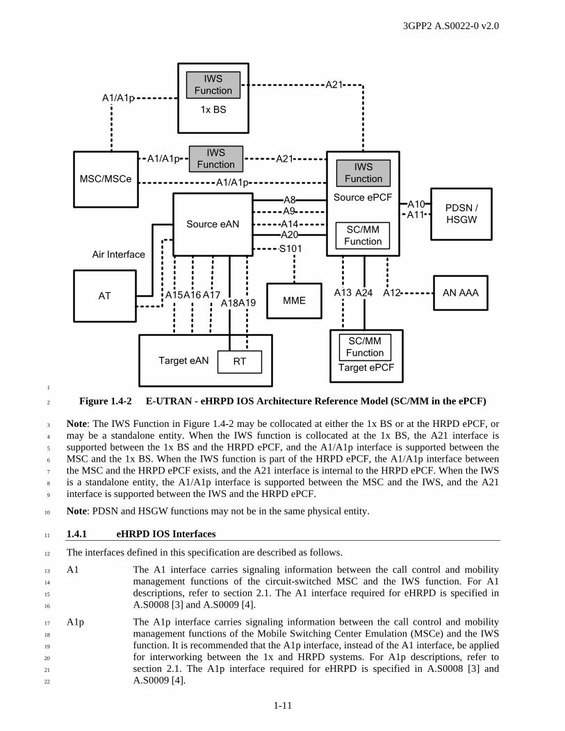
Figure 1.4-2 E-UTRAN - eHRPD IOS Architecture Reference Model (SC/MM in the ePCF).........1-11 4
Figure 1.13.1-1 eHRPD Packet Data Session State Transitions..............................................................1-18 5
Figure 3.2.1.1.1-1 E-UTRAN to eHRPD Pre-Registration – SC/MM at eAN Case ........................3-3 6
Figure 3.2.1.1.2-1 E-UTRAN to eHRPD Pre-Registration – SC/MM at ePCF Case.......................3-5 7
Figure 3.2.2.1-1 E-UTRAN to eHRPD Handoff – A8 Connected .............................................................3-7 8
Figure 3.2.2.2-1 E-UTRAN to eHRPD Handoff – A8 Disconnected.........................................................3-9 9
Figure 3.2.2.3-1 Active Handoff from E-UTRAN to eHRPD with Handover Between eANs................3-12 10
Figure 3.2.3.1-1 Dormant Handoff from E-UTRAN to eHRPD (Same eAN/ePCF) ...............................3-15 11
Figure 3.2.3.2-1 Dormant Handoff from E-UTRAN to eHRPD (Different eAN/ePCF) .........................3-16 12
Figure 3.2.3.3-1 Dormant Handoff from E-UTRAN to eHRPD with Prior Session Removal.................3-18 13
Figure 3.3.1-1 Non-Optimized eHRPD to E-UTRAN Dormant Handoff.............................................3-20 14
Figure 3.4.1-1 Re-authentication of an Idle eAT in eHRPD via S101 ..................................................3-21 15
16

3GPP2 A.S0022-0 v2.0
vi
Table of Tables 1
2
Table 3.1-1 Supported Call Flows for eHRPD....................................................................................3-1 3
Table 4.2.1.2-1 Cross Reference of IEs with Messages ..........................................................................4-23 4
Table 4.2.2.2-1 Cross Reference of IEs with Messages ..........................................................................4-28 5
Table 4.2.4.2-1 A16 Cross Reference of IEs with Messages ..................................................................4-35 6
7
8

3GPP2 A.S0022-0 v2.0
vii
Foreword 1
This foreword is not part of this standard. 2
The interface specifications defined in this document are based on A.S0008 [3] and A.S0009 [4]. This 3
document describes the interface protocols and procedures to support the Evolved High Rate Packet Data 4
(eHRPD) Interoperability Specification (IOS) features listed in section 1.1. Refer to section 1.6 for an 5
explanation of this specification’s reuse of High Rate Packet Data (HRPD) IOS transport requirements 6
and interface definitions. 7
This document was produced by TSG-A of the Third Generation Partnership Project 2. This document 8
was developed in accordance with the procedural guidelines of 3GPP2 and its Organizational Partners, 9
and represents the consensus position of these groups. 10
Note that there are two annex sections in this document. Annex A and B are normative and considered 11
part of this Standard. 12
13
14

3GPP2 A.S0022-0 v2.0
viii
1
(This page intentionally left blank) 2
3
4
5

3GPP2 A.S0022-0 v2.0
1-1
1 Introduction 1
This document defines the access network aspects of eHRPD systems that interwork with Enhanced 2
Universal Terrestrial Radio Access Network (E-UTRAN) and Evolved Packet Core (EPC) systems. 3
1.1 Overview 4
This document includes a description of the interface protocols and procedures to support the features and 5
functions described in section 1.14. Conformance to this standard may be claimed on a feature by feature 6
and/or interface by interface basis. If conformance on a given interface is claimed for a feature, it shall be 7
supported as defined in this standard. 8
In addition to the features and functions included in A.S0008 [3] and A.S0009 [4], this specification 9
supports: 10
Standalone eHRPD 11
Active handoff from E-UTRAN to eHRPD 12
Dormant handoff from E-UTRAN to eHRPD 13
Dormant handoff from eHRPD to E-UTRAN 14
Active handoff from E-UTRAN to eHRPD with handover between eANs 15
1.1.1 Purpose 16
The purpose of this document is to provide a standard and call flows for the eHRPD IOS interfaces within 17
the eHRPD Radio Access Network (RAN), and for interworking between E-UTRAN and eHRPD. 18
1.1.2 Scope 19
This document provides an interoperability specification for a RAN that supports eHRPD and handoff to 20
and from E-UTRAN. The RAN architecture in this document logically locates the Session Control and 21
Mobility Management (SC/MM) function in the Access Network (AN) for the architecture specified in 22
A.S0008 [3] or in the Packet Control Function (PCF) for the architecture specified in A.S0009 [4]. This 23
document contains message procedures and formats necessary to obtain this interoperability. 24
1.1.3 Document Convention 25
“Shall” and “shall not” identify requirements to be followed strictly to conform to the standard and from 26
which no deviation is permitted. “Should” and “should not” indicate that one of several possibilities is 27
recommended as particularly suitable, without mentioning or excluding others; that a certain course of 28
action is preferred but not necessarily required; or (in the negative form) that a certain possibility or 29
course of action is discouraged but not prohibited. “May” and “need not” indicate a course of action 30
permissible within the limits of the standard. “Can” and “cannot” are used for statements of possibility 31
and capability, whether material, physical, or causal. 32
In the Annexes that show changes relative to the base documents A.S0008 [3] and A.S0009 [4] an ellipsis 33
(…) indicates that the base document is unchanged. 34
1.2 References 35
References are either normative or informative. A normative reference is used to include another 36
document as a mandatory part of a 3rd Generation Partnership Project 2 (3GPP2) specification. 37
Documents that provide additional non-essential information are included in the informative references 38
section. 39
3GPP2 A.S0022-0 v2.0
1-2
1.2.1 Normative References 1
The following standards contain provisions which, through reference in this text, constitute provisions of 2
this standard. At the time of publication, the editions indicated were valid. All standards are subject to 3
revision, and parties to agreements based upon this document are encouraged to investigate the possibility 4
of applying the most recent editions of the standards indicated below. ANSI and TIA maintain registers of 5
currently valid national standards published by them. 6
[1] 3GPP: TS 23.402, Architecture Enhancements for non-3GPP accesses (Release 8). 7
[2] 3GPP: TS 29.276, Optimized Handover Procedures and Protocols between E-UTRAN 8
Access and cdma2000 HRPD Access – Stage 3 (Release 8). 9
[3] 3GPP2: A.S0008-C v2.0, Interoperability Specification (IOS) for High Rate Packet Data 10
(HRPD) Radio Access Network Interfaces with Session Control in the Access Network, 11
January 2009. 12
[4] 3GPP2: A.S0009-C v2.0, Interoperability Specification (IOS) for High Rate Packet Data 13
(HRPD) Radio Access Network Interfaces with Session Control in the Packet Control 14
Function, January 2009. 15
[5] 3GPP2: A.S0011-C v2.0, Interoperability Specification (IOS) for cdma2000 Access Network 16
Interfaces – Part 1 Overview, December 2005. 17
[6] 3GPP2: A.S0012-C v2.0, Interoperability Specification (IOS) for cdma2000 Access Network 18
Interfaces – Part 2 Transport, December 2005. 19
[7] 3GPP2: A.S0013-C v2.0, Interoperability Specification (IOS) for cdma2000 Access Network 20
Interfaces – Part 3 Features, December 2005. 21
[8] 3GPP2: A.S0014-C v2.0, Interoperability Specification (IOS) for cdma2000 Access Network 22
Interfaces – Part 4 (A1, A1p, A2, and A5 Interfaces), December 2005. 23
[9] 3GPP2: A.S0015-C v2.0, Interoperability Specification (IOS) for cdma2000 Access Network 24
Interfaces – Part 5 (A3 and A7 Interfaces), December 2005. 25
[10] 3GPP2: A.S0016-C v2.0, Interoperability Specification (IOS) for cdma2000 Access Network 26
Interfaces – Part 6 (A8 and A9 Interfaces), December 2005. 27
[11] 3GPP2: A.S0017-C v2.0, Interoperability Specification (IOS) for cdma2000 Access Network 28
Interfaces – Part 7 (A10 and A11 Interfaces), December 2005. 29
[12] 3GPP2: C.S0001-D v2.0, Introduction to cdma2000 Standards for Spread Spectrum Systems, 30
September 2005. 31
[13] 3GPP2: C.S0002-D v2.0, Physical Layer Standard for cdma2000 Spread Spectrum Systems, 32
September 2005. 33
[14] 3GPP2: C.S0003-D v2.0, Medium Access Control (MAC) Standard for cdma2000 Spread 34
Spectrum Systems, September 2005. 35
[15] 3GPP2: C.S0004-D v2.0, Signaling Link Access Control (LAC) Standard for cdma2000 36
Spread Spectrum Systems, September 2005. 37
[16] 3GPP2: C.S0005-D v2.0, Upper Layer (Layer 3) Signaling Standard for cdma2000 Spread 38
Spectrum Systems, September 2005. 39
[17] 3GPP2: C.S0006-D v2.0, Analog Signaling Standard for cdma2000 Spread Spectrum 40
Systems, September 2005. 41
[18] 3GPP2: C.S0024-B v3.0, cdma2000 High Rate Packet Data Air Interface Specification, 42
September 2009. 43
3GPP2 A.S0022-0 v2.0
1-3
[19] 3GPP2: C.S0057-D v1.0, Band Class Specification for cdma2000 Spread Spectrum Systems, 1
September 2009. 2
[20] 3GPP2: C.S0063-A v2.0, cdma2000 High Rate Packet Data Supplemental Services, March 3
2007. 4
[21] 3GPP2: C.S0067-A v1.0, Generic Key Exchange Protocol for cdma2000 High Rate Packet 5
Data Air Interface, February 2009. 6
[22] 3GPP2: C.S0082-0 v1.0, Circuit Services Notification Application Specification for 7
cdma2000 High Rate Packet Data, August 2006. 8
[23] 3GPP2: C.S0087-0 v2.0, E-UTRAN - cdma2000 HRPD Connectivity and Interworking: Air 9
Interface Specification, January 2010. 10
[24] 3GPP2: X.S0011-E v1.0, Wireless IP Network Standard, November 2009. 11
[25] 3GPP2: X.S0057-0 v2.0, E-UTRAN - eHRPD Connectivity and Interworking: Core Network 12
Aspects, December 2009. 13
[26] IETF: RFC 1661, Point-to-Point Protocol, July 1994. 14
[27] IETF: RFC 1994, PPP Challenge Handshake Authentication Protocol (CHAP), August 15
1996. 16
[28] IETF: RFC 2865, Remote Authentication Dial In User Service (RADIUS), June 2000. 17
[29] IETF: RFC 3095, RObust Header Compression (ROHC): Framework and four profiles: 18
RTP, UDP, ESP, and uncompressed, July 2001. 19
[30] IETF: RFC 3115, Mobile IP Vendor/Organization-Specific Extensions, April 2001. 20
[31] Internet Assigned Numbers Authority: RObust Header Compression (ROHC) Profile 21
Identifiers, http://www.iana.org/assignments/rohc-pro-ids, May 2008. 22
23
1.2.2 Informative References 24
[I-1] IETF: RFC 3241, Robust Header Compression (ROHC) over PPP, April 2002. 25
26
27
1.3 Terminology 28
29
1.3.1 Acronyms 30
3GPP 3rd Generation Partnership Project
3GPP2 3rd Generation Partnership Project 2
AAA Authentication, Authorization and Accounting server
ADDS Application Data Delivery Service
AN Access Network
ANID Access Network Identifiers
APN Access Point Name
AT Access Terminal

3GPP2 A.S0022-0 v2.0
1-4
BLOB BLock Of Bits
BS Base Station
CANID Current Access Network Identifiers
CHAP Challenge Handshake Authentication Protocol
CID Context IDentifier
CSNA Circuit Services Notification Application
CVSE Critical Vendor/Organization Specific Extension
DoS Data Over Signaling
DRI Data Ready Indicator
eAN Evolved Access Network
eAT Evolved Access Terminal
eHRPD Evolved High Rate Packet Data
EPC Evolved Packet Core
ePCF Evolved Packet Control Function
EPS Evolved Packet System
ESSIR Extended Session State Information Record
E-UTRAN Enhanced Universal Terrestrial Radio Access Network
GKE Generic Key Exchange
GRE Generic Routing Encapsulation
HRPD High Rate Packet Data
HSGW HRPD Serving Gateway
HSS Home Subscriber Server
IANA Internet Assigned Numbers Authority
IE Information Element
IMSI International Mobile Subscriber Identity
IOS Inter-Operability Specification
IP Internet Protocol
IWS Interworking Solution
LCM Long Code Mask
LCP Link Control Protocol
MAC Medium Access Control
MEI Mobility Event Indicator
MEID Mobile Equipment Identity
MME Mobility Management Entity
MN ID Mobile Node Identification
MRRU Maximum Reconstructed Reception Unit
MS Mobile Station
MSC Mobile Switching Center
MSCe Mobile Switching Center Emulation
NAI Network Access Identifier
NAS Non-access Stratum
NID Network Identification
NVSE Normal Vendor Specific Extension

3GPP2 A.S0022-0 v2.0
1-5
P-GW PDN GW (Packet Data Network Gateway)
PANID Previous Access Network Identifiers
PCF Packet Control Function
PCRF Policy and Charging Rules Function
PDN Packet Data Network
PDSI Packet Data Service Instance
PDSN Packet Data Serving Node
PMIP Proxy Mobile Internet Protocol
PMK Pairwise Master Key
PPP Point-to-Point Protocol
PZID Packet Zone Identification
QoS Quality of Service
RADIUS Remote Authentication Dial-In User Service
RAN Radio Access Network
RFC Request for Comment
RLP Radio Link Protocol
ROHC RObust Header Compression
RT Radio Transceiver
S-GW Serving Gateway
SAP Signaling Adaptation Protocol
SC/MM Session Control / Mobility Management
SDB Short Data Burst
SID System Identification
SLP Signaling Link Protocol
SSIR Session State Information Record
TCA Traffic Channel Assignment
TFT Traffic Flow Template
UATI Unicast Access Terminal Identifier
VoIP Voice over Internet Protocol
VSA Vendor Specific Attribute
1
1.3.2 Definitions 2
1x Refer to “cdma2000®1 1x”. 3
Access Authentication A procedure in A.S0008 [3] in which the Access Terminal (AT) is 4
authenticated by the AN-AAA (Authentication, Authorization and 5
Accounting server). 6
1 cdma2000® is the trademark for the technical nomenclature for certain specifications and standards of the Organizational Partners (OPs) of 3GPP2. Geographically (and as of the date of publication), cdma2000® is a registered trademark of the Telecommunications Industry Association (TIA-USA) in the United States.

3GPP2 A.S0022-0 v2.0
1-6
Access Stream A stream to which a packet application bound to an access network is 1
attached. Access stream is used for access authentication. 2
AN-Based ROHC RObust Header Compression (ROHC) where compression and 3
decompression are performed in the AN. ROHC channels for AN-Based 4
ROHC terminate in the AT and AN. 5
cdma2000 1x The version of cdma2000 defined by C.S0001~C.S0006 [12]~[17] and also 6
supported by A.S0011~ A.S0017 [5]~[11]. 7
Connected State Session Transfer 8
Connected State Session Transfer is the process of transferring the session of 9
an AT from one AN to another AN. Connected State Session Transfer can 10
either be without cross-connectivity support (i.e., hard handoff) or with 11
cross-connectivity support. 12
Connection A connection, in this specification, refers to either an air interface connection 13
or a signaling or user traffic connection in the RAN. An air interface 14
connection is a particular state of the air-link in which the access terminal is 15
assigned a Forward Traffic Channel, a Reverse Traffic Channel and 16
associated Medium Access Control (MAC) Channels or a virtual connection 17
(refer to C.S0087 [23]). During a single HRPD session the AT and the AN 18
can open and can close a connection multiple times. A signaling or user 19
traffic connection is a particular state shared between two nodes in the RAN 20
or between a node in the RAN and a network entity outside the RAN. 21
Examples of a connection in the RAN are A8 and A10 connections, which 22
are used for user traffic. 23
eHRPD For purposes of this document, an eHRPD system is a RAN -- Evolved 24
Access Network (eAN) and Evolved Packet Control Function (ePCF) -- that 25
supports evolved mode (C.S0087 [23]) operation in addition to legacy mode 26
(C.S0024 [18] and C.S0063 [20]) operation. An eHRPD system may be 27
standalone or may support interworking with E-UTRAN. Refer also to 28
Evolved Access Network. 29
EPC EPC consists of the Packet Data Network (P-GW) and other entities as 30
defined by 3GPP. The HRPD Serving Gateway (HSGW) connects the 31
eHRPD RAN to the EPC. 32
EPS Evolved Packet System (EPS) consists of E-UTRAN and EPC. 33
E-UTRAN The E-UTRAN consists of a set of eNodeBs (refer to TS 23.402 [1]). For 34
purposes of this document, the E-UTRAN is the network that supports 35
Evolved Universal Terrestrial Radio Access. 36
Flow ID A synonym for Reservation Label. 37
Flow Profile ID An identifier of the service needs for an application flow. Refer to A.S0008 38
[3] and A.S0009 [4]. 39
Forward ROHC Channel A unidirectional compressor/decompressor pair (refer to RFC 3095 [29]) that 40
sends ROHC packets from Packet Data Serving Node (PDSN) or AN to AT. 41
The compressor transforms original packets into ROHC packets. 42
Granted QoS Sub BLOB The Quality of Service (QoS) Sub BLOB (Block of Bits) containing the QoS 43
granted for a given IP flow. Refer to X.S0057 [25] and C.S0087 [23]. 44
Hard Handoff A handoff characterized by a temporary disconnection of the Traffic 45
Channel. Hard handoffs occur when the AT is transferred between disjoint 46
Active Sets, or when the Frequency Assignment changes. 47
3GPP2 A.S0022-0 v2.0
1-7
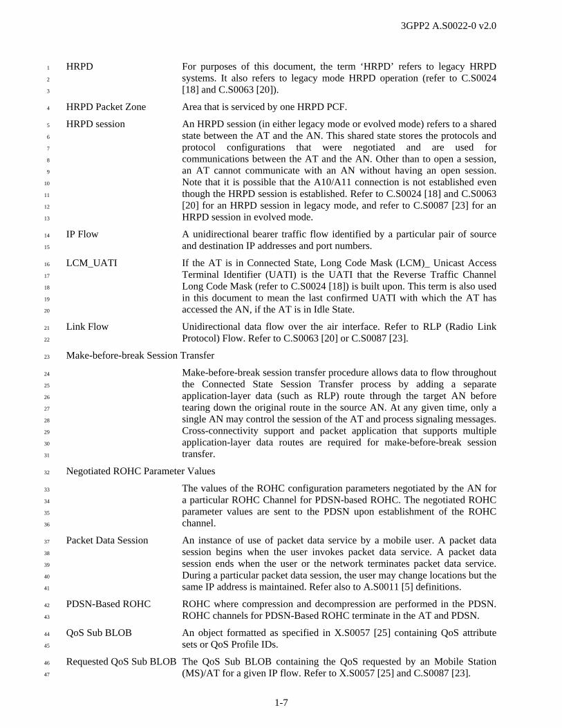
HRPD For purposes of this document, the term ‘HRPD’ refers to legacy HRPD 1
systems. It also refers to legacy mode HRPD operation (refer to C.S0024 2
[18] and C.S0063 [20]). 3
HRPD Packet Zone Area that is serviced by one HRPD PCF. 4
HRPD session An HRPD session (in either legacy mode or evolved mode) refers to a shared 5
state between the AT and the AN. This shared state stores the protocols and 6
protocol configurations that were negotiated and are used for 7
communications between the AT and the AN. Other than to open a session, 8
an AT cannot communicate with an AN without having an open session. 9
Note that it is possible that the A10/A11 connection is not established even 10
though the HRPD session is established. Refer to C.S0024 [18] and C.S0063 11
[20] for an HRPD session in legacy mode, and refer to C.S0087 [23] for an 12
HRPD session in evolved mode. 13
IP Flow A unidirectional bearer traffic flow identified by a particular pair of source 14
and destination IP addresses and port numbers. 15
LCM_UATI If the AT is in Connected State, Long Code Mask (LCM)_ Unicast Access 16
Terminal Identifier (UATI) is the UATI that the Reverse Traffic Channel 17
Long Code Mask (refer to C.S0024 [18]) is built upon. This term is also used 18
in this document to mean the last confirmed UATI with which the AT has 19
accessed the AN, if the AT is in Idle State. 20
Link Flow Unidirectional data flow over the air interface. Refer to RLP (Radio Link 21
Protocol) Flow. Refer to C.S0063 [20] or C.S0087 [23]. 22
Make-before-break Session Transfer 23
Make-before-break session transfer procedure allows data to flow throughout 24
the Connected State Session Transfer process by adding a separate 25
application-layer data (such as RLP) route through the target AN before 26
tearing down the original route in the source AN. At any given time, only a 27
single AN may control the session of the AT and process signaling messages. 28
Cross-connectivity support and packet application that supports multiple 29
application-layer data routes are required for make-before-break session 30
transfer. 31
Negotiated ROHC Parameter Values 32
The values of the ROHC configuration parameters negotiated by the AN for 33
a particular ROHC Channel for PDSN-based ROHC. The negotiated ROHC 34
parameter values are sent to the PDSN upon establishment of the ROHC 35
channel. 36
Packet Data Session An instance of use of packet data service by a mobile user. A packet data 37
session begins when the user invokes packet data service. A packet data 38
session ends when the user or the network terminates packet data service. 39
During a particular packet data session, the user may change locations but the 40
same IP address is maintained. Refer also to A.S0011 [5] definitions. 41
PDSN-Based ROHC ROHC where compression and decompression are performed in the PDSN. 42
ROHC channels for PDSN-Based ROHC terminate in the AT and PDSN. 43
QoS Sub BLOB An object formatted as specified in X.S0057 [25] containing QoS attribute 44
sets or QoS Profile IDs. 45
Requested QoS Sub BLOB The QoS Sub BLOB containing the QoS requested by an Mobile Station 46
(MS)/AT for a given IP flow. Refer to X.S0057 [25] and C.S0087 [23]. 47

3GPP2 A.S0022-0 v2.0
1-8
Reservation Air interface resources needed to carry one or more IP flows. Refer to 1
C.S0087 [23] or C.S0063 [20]. 2
Reservation Label An identifier, which combined with a direction, uniquely identifies a 3
reservation for an AT. Reservation labels are also used as Flow IDs. 4
Reverse ROHC Channel A unidirectional compressor/decompressor pair (refer to RFC 3095 [29]) that 5
sends ROHC packets from AT to PDSN or AN. The compressor transforms 6
original packets into ROHC packets. 7
RLP Flow Unidirectional data flow over the air interface. This specification refers to 8
this as Link flow. Refer to C.S0087 [23]. 9
ROHC A protocol defined by IETF (refer to RFC 3095 [29], RFC 3241 [I-1]). 10
Unless otherwise specified, “ROHC” in this document refers to ROHC on 11
SO67. For example, “negotiated ROHC parameter values” do not apply to 12
ROHC over Point-to-Point Protocol (PPP) (refer to RFC 3095 [29]). 13
ROHC Channel A unidirectional compressor/decompressor pair (refer to RFC 3095 [29]). In 14
this document, a ROHC Channel may be a Forward ROHC Channel or a 15
Reverse ROHC Channel. One A8/A10 connection, which is bidirectional, 16
may carry one Forward ROHC Channel, or one Reverse ROHC Channel, or 17
one Forward and one Reverse ROHC Channel. 18
ROHC Configuration Parameters 19
Mandatory parameters that have the same values at both compressor and 20
decompressor of a ROHC channel. In this document, this term refers to the 21
MAX_CID (Context Identifier), LARGE_CIDS, PROFILES, and Maximum 22
Reconstructed Reception Unit (MRRU). The parameter FEEDBACK_FOR 23
is not used in this document. Refer to RFC 3095 [29]. 24
ROHC on SO67 The capability to associate ROHC channels with A8/A10 connections having 25
service option 67. 26
Service Connection A bidirectional logical connection between the AT and PDSN that may 27
persist for the life of the PPP session. A service connection is identified by 28
the SR_ID2 and has an associated service option value. A service connection 29
may be mapped to a unique forward air interface link flow, reverse air 30
interface link flow, A8 connection and A10 connection associated with the 31
AT at any given time. PPP signaling is carried over the main service 32
connection, which is associated with the main A8/A10 connection. Auxiliary 33
service connections may be established as needed. Every IP flow is 34
associated with a service connection. 35
Service Stream The HRPD stream used when exchanging data between the AT and the 36
PDSN. Refer to C.S0087 [23]. 37
Serving RT The Radio Transceiver (RT) that contains the serving sector. Refer to 38
C.S0087 [23]. 39
Session Transfer with cross-connectivity support 40
Session Transfer with cross-connectivity support is a Connected State 41
Session Transfer process where both the source AN and the target AN can 42
2 There are some situations where the SR_ID of the service connection may change; e.g., upon a failed inter-ePCF session transfer.

3GPP2 A.S0022-0 v2.0
1-9
cross-connect to the current Active Set. Make-before-break Session Transfer 1
is Session Transfer with cross-connectivity support which utilizes two routes. 2
SR_ID Identifier of a service connection. SR_ID 1 identifies the main service 3
connection. 4
Subnet The set of sectors that advertise the same subnet mask and for which the 5
AND operation performed on the Sector ID and the subnet mask results in 6
the same value. A subnet is intended to allow the network to define the 7
boundary at which an idle AT is required to access the system. Refer to 8
C.S0087 [23]. 9
Subscriber QoS Profile The set of QoS-related information sent from the PDSN that the RAN uses to 10
authorize QoS requests for a given subscriber. Refer to X.S0057 [25]. 11
Terminal Authentication A procedure in A.S0009 [4] in which the AT is authenticated by the AN-12
AAA. 13
14
1.4 HRPD IOS Architecture Reference Model 15
The eHRPD IOS messaging and call flows are based on the Architecture Reference Model shown in 16
Figure 1.4-1 (Session Control and Mobility Management in the evolved Access Network) and in Figure 17
1.4-2 (Session Control and Mobility Management in the evolved Packet Control Function). In the figures, 18
solid lines indicate signaling and bearer and dashed lines indicate only signaling. 19
The eHRPD call flows include the E-UTRAN and other 3GPP access entities (S-GW, P-GW, HSS and 20
PCRF). Refer to TS 23.402 [1] for the architecture model and descriptions of these network entities and 21
associated interfaces. 22

3GPP2 A.S0022-0 v2.0
1-10
ePCF
A8PDSN /HSGW
A9
A10
A11
AN AAA
A13AT
A12Air Interface
MSC/MSCe
Source eAN
SC/MMFunction
Target eAN
SC/MMFunction
IWSFunctionA1/A1p
1x BS
A21
A1/A1p
IWSFunction
IWSFunctionA1/A1p A21
A16 A17A18 A19
RT
S101
MME
A24
1
Figure 1.4-1 E-UTRAN - eHRPD IOS Architecture Reference Model (SC/MM in the eAN) 2
Note: The Interworking Solution (IWS) Function in Figure 1.4-1 may be collocated at either the 1x Base 3
Station (BS) or at the HRPD eAN, or may be a standalone entity. When the IWS function is collocated at 4
the 1x BS, the A21 interface is supported between the 1x BS and the HRPD eAN, and the A1/A1p 5
interface is supported between the Mobile Switching Center (MSC) and the 1x BS. When the IWS 6
function is part of the HRPD eAN, the A1/A1p interface between the MSC and the HRPD eAN exists, 7
and the A21 interface is internal to the HRPD eAN. When the IWS is a standalone entity, the A1/A1p 8
interface is supported between the MSC and the IWS, and the A21 interface is supported between the 9
IWS and the HRPD eAN. 10
Note: PDSN and HSGW functions may not be in the same physical entity. 11
3GPP2 A.S0022-0 v2.0
1-11
Source eAN
Target ePCF
Source ePCFA8PDSN /HSGW
A20
A10
AN AAAAT A12
Air Interface
A16
A9A14 SC/MM
Function
SC/MMFunction
MSC/MSCe A1/A1p
1x BSA1/A1p
A21
A1/A1p A21
A15 A17A18A19
Target eAN RT
S101
MME
IWSFunction
IWSFunction
IWSFunction
A13 A24
A11
1
Figure 1.4-2 E-UTRAN - eHRPD IOS Architecture Reference Model (SC/MM in the ePCF) 2
Note: The IWS Function in Figure 1.4-2 may be collocated at either the 1x BS or at the HRPD ePCF, or 3
may be a standalone entity. When the IWS function is collocated at the 1x BS, the A21 interface is 4
supported between the 1x BS and the HRPD ePCF, and the A1/A1p interface is supported between the 5
MSC and the 1x BS. When the IWS function is part of the HRPD ePCF, the A1/A1p interface between 6
the MSC and the HRPD ePCF exists, and the A21 interface is internal to the HRPD ePCF. When the IWS 7
is a standalone entity, the A1/A1p interface is supported between the MSC and the IWS, and the A21 8
interface is supported between the IWS and the HRPD ePCF. 9
Note: PDSN and HSGW functions may not be in the same physical entity. 10
1.4.1 eHRPD IOS Interfaces 11
The interfaces defined in this specification are described as follows. 12
A1 The A1 interface carries signaling information between the call control and mobility 13
management functions of the circuit-switched MSC and the IWS function. For A1 14
descriptions, refer to section 2.1. The A1 interface required for eHRPD is specified in 15
A.S0008 [3] and A.S0009 [4]. 16
A1p The A1p interface carries signaling information between the call control and mobility 17
management functions of the Mobile Switching Center Emulation (MSCe) and the IWS 18
function. It is recommended that the A1p interface, instead of the A1 interface, be applied 19
for interworking between the 1x and HRPD systems. For A1p descriptions, refer to 20
section 2.1. The A1p interface required for eHRPD is specified in A.S0008 [3] and 21
A.S0009 [4]. 22
3GPP2 A.S0022-0 v2.0
1-12
A8 The A8 interface carries user traffic between the Access Network and the PCF. For A8 1
descriptions, refer to section 2.2. The A8 interface required for standalone eHRPD and 2
EPS - eHRPD interworking is specified in Annex A. 3
A9 The A9 interface carries signaling information between the AN and the PCF. For A9 4
descriptions, refer to section 2.2. The A9 interface required for standalone eHRPD and 5
EPS - eHRPD interworking is specified in Annex A. 6
A10 The A10 interface carries user traffic between the PCF and the PDSN/HSGW. For A10 7
descriptions, refer to section 2.3. The A10 interface required for standalone eHRPD and 8
EPS - eHRPD interworking is specified in Annex B. 9
A11 The A11 interface carries signaling information between the PCF and the PDSN/HSGW. 10
For A11 descriptions, refer to section 2.3. The A11 interface required for standalone 11
eHRPD and EPS - HRPD interworking is specified in Annex B. 12
A12 The A12 interface carries signaling information related to access/terminal authentication 13
between the SC/MM function and the AN-AAA. For a description of the A12 interface, 14
refer to section 2.4. 15
A13 For A.S0008 architecture, the A13 interface carries signaling information between the 16
SC/MM function in the source AN and the SC/MM function in the target AN for dormant 17
state session transfer and inter-AN paging when the AT is in idle state. For A.S0009 18
architecture, the A13 interface is between the SC/MM function in the source PCF and the 19
SC/MM function in the target PCF. For a description of the A13 interface, refer to section 20
2.5. 21
A14 For A.S0009 architecture, the A14 interface carries signaling information between the 22
SC/MM function in the PCF and the AN. The A14 interface is not applicable to A.S0008 23
architecture. For a description of the A14 interface, refer to section 2.6. 24
A15 For A.S0009 architecture, the A15 interface carries signaling information between ANs 25
when inter-AN paging is used. The A15 interface is not applicable to A.S0008 26
architecture. For a description of the A15 interface, refer to section 2.7. 27
A16 The A16 interface carries signaling information between the source AN and the target 28
AN for HRPD Inter-AN Connected State Session Transfer (hard handoff or with cross-29
connectivity support). For a description of the A16 interface, refer to section 2.8. 30
A17 The A17 interface carries signaling information between a source AN and a target AN to 31
manage resources in support of inter-eAN cross-connectivity (soft/softer handoff). The 32
A17 interface establishes dedicated endpoints for the A18 and A19 interfaces. 33
Additionally, the A17 interface tunnels air interface forward control channel signaling 34
messages from the source AN to a target AN that has sectors in the AT’s Active Set to be 35
transmitted to the AT. For a description of the A17 interface, refer to section 2.9. 36
A18 The A18 interface transports user traffic (i.e., air interface traffic channel data) for an AT 37
between the source AN and a target RT during cross-connectivity. The A18 interface 38
endpoints are set up using the A17 interface. For a description of the A18 interface, refer 39
to section 2.9. 40
A19 The A19 interface carries RT-specific bearer-related cross-connectivity control messages 41
for an AT between the source AN and a target RT. The A19 interface endpoints are set up 42
using the A17 interface. For a description of the A19 interface, refer to section 2.9. 43
A20 For A.S0009 architecture, the A20 interface carries user traffic between the SC/MM 44
function in the PCF and the AN. The A20 interface is not applicable to A.S0008 45
architecture. For a description of the A20 interface, refer to section 2.10. 46
A21 The A21 interface carries signaling information between the HRPD AN and the IWS. For 47
a description of the A21 interface, refer to section 2.11. 48

3GPP2 A.S0022-0 v2.0
1-13
A24 The A24 interface carries buffered user data from the source AN/PCF to the target 1
AN/PCF for an AT, during A13 session transfer. The target AN/PCF interface endpoint is 2
transmitted to the source AN/PCF in the A13-Session Information Request message. 3
Refer to section 2.12. 4
S101 The S101 interface carries signaling information between the HRPD eAN and the 5
Mobility Management Entity (MME). For a description of the S101 interface, refer to 6
section 2.13. 7
1.4.2 eHRPD IOS Network Entities 8
1x Base Station A 1x Base Station (1x BS) operates on the cdma2000 1x air interface defined 9
by C.S0001~C.S0006 [12]~[17] and also supports the 1x IOS specified in 10
A.S0011~A.S0017 [5]~[11]. 11
Access Network A logical entity in the RAN used for radio communications with the AT. An 12
AN contains one or more RTs and is equivalent to a base station in 1x 13
systems. AN in this specification refers to both legacy AN and evolved AN. 14
Refer to the definition of Legacy Access Network and Evolved Access 15
Network. 16
Access Terminal A device providing data connectivity to a user. An AT may be connected to a 17
computing device such as a laptop personal computer or it may be a self-18
contained data device such as a personal digital assistant. An AT is 19
equivalent to a mobile station in 1x systems. The term AT applies to both an 20
Evolved Access Terminal (eAT) and a legacy AT. 21
AN-AAA An entity that performs access/terminal authentication functions for the 22
RAN. 23
Evolved Access Network Access Network that supports operations for EPS – eHRPD RAN 24
interworking specified in this specification, in addition to legacy access 25
network capabilities. 26
Evolved Access Terminal AT that supports both evolved mode (refer to C.S0087 [23]) and legacy 27
mode operation (refer to C.S0024 [18] and C.S0063 [20]). An eAT is 28
referred to as a UE in TS 23.402 [1], TS 29.276 [2] and X.S0057 [25]. 29
Evolved Packet Control Function 30
Packet Control Function that supports operations for EPS – eHRPD RAN 31
interworking specified in this specification, in addition to legacy packet 32
control function capabilities. 33
HRPD Serving Gateway The HSGW is the HRPD Serving Gateway that connects the evolved HRPD 34
access network with the EPC as a trusted non-3GPP access network. 35
IWS Function IWS Function is logically collocated at the 1x BS or the AN, or as a 36
standalone entity. In this standard the term IWS is used without regard to the 37
location of the IWS. When it is necessary to make a distinction with regard to 38
the location of the IWS, that is explicitly stated. IWS provides the following 39
functions: 40
Message Translation: This function translates between IOS A1/A1p 41
messages received from/sent to an MSC and 1x air interface signaling 42
messages sent/received over the HRPD air interface. 43
1x Parameters Storage: This function stores 1x radio parameters required 44
for Circuit Services Notification Application (CSNA) support. 45

3GPP2 A.S0022-0 v2.0
1-14
1x PN Offset and BTS Cell ID Mapping: This function enables to map a 1
pair of 1x PN pilot information and HRPD sector information into BTS 2
Cell ID. 3
RAND Generation: This optional function provides the RAND used for 4
1x authentication. This function may be in the HRPD AN. When several 5
nodes in the RAN have this function, the RAND value provided by the 6
IWS is used. 7
Legacy Access Network An Access Network that complies to the specifications in A.S0008 [3] and/or 8
A.S0009 [4] and does not support evolved mode operation in this 9
specification. 10
Legacy Access Terminal An AT that does not support evolved mode is referred to as a legacy AT. 11
Legacy Packet Control Function 12
A Packet Control Function that complies to the specifications in A.S0008 [3] 13
and/or A.S0009 [4] and does not support evolved mode operation in this 14
specification. 15
Mobile Station In 1x systems, the Mobile Station (MS) is an entity in the public cellular 16
radio telecommunications service intended to be used while in motion or 17
during halts at unspecified points. In this specification, the term MS may also 18
refer to an AT where text that is applicable to 1x systems has been extended 19
to apply to HRPD and/or eHRPD systems. 20
Mobile Switching Center The MSC switches MS/AT-originated or MS/AT-terminated traffic. An MSC 21
connects to one or more ANs. It may connect to other public networks 22
(PSTN, ISDN, etc.), other MSCs in the same network, or MSCs in different 23
networks. (It has been referred to as Mobile Telephone Switching Office, 24
MTSO.) It provides the interface for user traffic between the wireless 25
network and other public switched networks, or other MSCs. 26
In this document, for signaling, the term MSC refers to either a circuit-27
switched MSC or an MSCe. In situations where a statement applies to either 28
the circuit-switched or packet-based MSC exclusively, the type of MSC is 29
specifically identified (i.e., “circuit-switched MSC” or “MSCe”). 30
Mobility Management Entity 31
The MME is defined in TS 23.402 [1]. 32
MSC Emulation (MSCe) The MSCe provides processing and control for calls and services. The MSCe 33
provides signaling capabilities equivalent to a circuit-switched MSC on the 34
A1p interface. The MSCe connects to an AN via IP based protocols. 35
Packet Control Function An entity in the radio access network that manages the relay of packets 36
between the AN and the PDSN/HSGW. PCF in this specification refers to 37
both legacy PCF and evolved PCF. Refer to the definition of Legacy Packet 38
Control Function and Evolved Packet Control Function. 39
Packet Data Serving Node An entity that routes AT originated or AT terminated packet data traffic. A 40
PDSN establishes, maintains and terminates link layer sessions to ATs. 41
PDSN in this specification refers to legacy PDSN that supports legacy HRPD 42
session with AT or eAT. 43
Radio Access Network The network entities providing data connectivity between the packet 44
switched data network (typically the Internet) and the AT. The RAN may be 45
divided into the following logical entities: ANs, AN-AAAs, and PCFs. The 46
interfaces between these entities, the interfaces between the PCF and the 47

3GPP2 A.S0022-0 v2.0
1-15
PDSN, and the interfaces between the AN and the MSC are considered parts 1
of the RAN. Refer to section 1.4. 2
RT An RT is a component of an AN comprising a collection of sectors that 3
transmit the same power control command to an AT. An RT is also referred 4
to as a cell on the air interface (refer to C.S0087 [23]). 5
SC/MM Function: SC/MM is logically located in the AN for the A.S0008 architecture or the 6
PCF for the A.S0009 architecture and includes the following functions: 7
Storage of HRPD session related information: This function keeps 8
HRPD session related information (e.g., Keep Alive timer, MNID, 9
mapping between MNID and UATI, etc.) for idle ATs. 10
Assignment of UATI: This function assigns a new UATI to an AT. 11
Access Authentication for the A.S0008 architecture: This function 12
performs the access authentication procedure. This function judges 13
whether an AT should be authenticated or not when the AT is accessing 14
the HRPD RAN. The SC/MM performs PPP procedures for access 15
authentication. 16
Terminal Authentication for the A.S0009 architecture: This function 17
performs the terminal authentication procedure. This function judges 18
whether an AT should be authenticated or not when the AT is accessing 19
the HRPD RAN. The SC/MM performs Point-to-Point Protocol (PPP) 20
procedures for terminal authentication. 21
Mobility Management: This function manages the location of an AT. 22
23
1.5 HRPD Micro-Mobility and Macro-Mobility Concepts 24
Refer to A.S0008 [3] and A.S0009 [4]. 25
1.6 Compatibility with IOS Standards 26
The E-UTRAN-eHRPD IOS architecture reference model in section 1.4 includes the following interfaces 27
that also exist in the 1x architecture reference model (refer to A.S0011 [5]): A1/A1p, A8/A9, and 28
A10/A11. To the extent possible, this specification reuses the 1x IOS transport requirements and interface 29
definitions for these interfaces. Some changes are required for these interfaces to work when used in 30
HRPD systems. For example, HRPD service option values are different from 1x service option values. 31
The HRPD IOS version specified in A.S0008 [3] and A.S0009 [4] are used as the “base documents” for 32
this specification. The changes required to A.S0008 [3] and A.S0009 [4] for eHRPD are shown in Annex 33
A and Annex B. 34
1.7 Compatibility with 3GPP Standards 35
The E-UTRAN-eHRPD IOS architecture reference model includes the S101 interface. This interface is 36
used to carry signaling information related to pre-registration, handoff preparation and execution between 37
the eHRPD and 3GPP networks. The transport requirements and interface definitions are specified in TS 38
29.276 [2] for this interface. Transport and message encapsulation over S101 are specified in the Evolved 39
3GPP Packet Switched architecture reference model (refer to TS 23.402 [1]), while the E-UTRAN-40
eHRPD IOS contains the eHRPD specific information exchanged with the eAT when it is connected to 41
the 3GPP network. 42
1.8 Message Body, Coding, Ordering, and Interpretation of Elements 43
Refer to A.S0008 [3] and A.S0009 [4]. 44

3GPP2 A.S0022-0 v2.0
1-16
1.9 Forward Compatibility Guidelines 1
Refer to A.S0008 [3] and A.S0009 [4]. 2
1.10 Message Processing Guidelines 3
Refer to A.S0008 [3] and A.S0009 [4]. 4
1.11 Message Definition Guidelines 5
Refer to A.S0008 [3] and A.S0009 [4]. 6
1.12 eHRPD IOS Assumptions 7
For legacy mode operation, refer to A.S0008 [3] and A.S0009 [4]. For evolved mode operation, this 8
section describes assumptions in this standard. 9
1.12.1 IOS Assumptions 10
The following assumptions are made regarding eAT, eAN, ePCF and HSGW behavior: 11
1. An evolved mode packet data session may transition from a serving E-UTRAN to a serving eHRPD 12
system and from a serving eHRPD system to a serving E-UTRAN. 13
2. A legacy mode packet data session may transition from a serving legacy HRPD system to a serving 14
eHRPD system and from a serving eHRPD system to a serving legacy HRPD system, with the HRPD 15
session transferred via the A13 interface in both cases. In this case, the serving eHRPD system 16
operates in legacy mode. In addition, the eHRPD system may optionally support A13 session transfer 17
with personality switch from evolved mode on eHRPD to legacy mode on HRPD. 18
3. After the UE transitions to a serving eHRPD system from a serving legacy HRPD system, it may 19
choose to renegotiate the eHRPD session and create an evolved packet data session with the HSGW 20
with new IP addresses. 21
4. An eHRPD system can support legacy ATs operating in legacy mode, eATs operating in evolved 22
mode, and eATs operating in legacy mode. 23
5. For systems with SC/MM in the eAN, subnets do not span more than one HRPD packet zone. There 24
may be more than one subnet within an HRPD packet zone and intra-ePCF handoffs may occur. 25
6. For the case of dormant inter-ePCF handoff, the target ePCF uses the HSGW address received from 26
the source eAN/ePCF to send the A11-Registration Request message. Otherwise, the target ePCF 27
uses the HSGW selection algorithm (if supported and if the International Mobile Subscriber Identity, 28
IMSI, is available) or internal algorithms (e.g., using MEID/ESN) to select an HSGW. 29
7. Following a dormant handoff, the target eAN may send the Access Network Identifiers (ANID) to the 30
target ePCF. If the eAT sends the System Identification (SID), Network Identification (NID), and 31
Packet Zone Identification (PZID), then the ANID consists of a triplet containing the received values. 32
If the eAT does not send the triplet, or the eAN chooses not to request this information from the eAT, 33
then the target eAN may send the ANID received in the A13-Session Information Response message 34
from the source eAN. If the target ePCF supports ANIDs, then it sets the Previous Access Network 35
Identifiers (PANID) to the ANID received from the target eAN, and the Current Access Network 36
Identifiers (CANID) to its own ANID in the A11 messages. 37
8. For the instance of Packet Application terminated in the eAN, the eAT supports Challenge Handshake 38
Authentication Protocol (CHAP) access/terminal authentication. In this case, the eAT sends a 39
Network Access Identifier (NAI) of the form specified in RFC 1994 [27]. 40
9. For the instance of Packet Application terminated in the eAN (i.e., eAN access/terminal 41
authentication), the generation of the NAI and password are the responsibility of the service provider. 42

3GPP2 A.S0022-0 v2.0
1-17
The NAI and password should be chosen and managed using procedures that minimize the likelihood 1
of compromise. 2
10. If access/terminal authentication is used, the eAN or ePCF always proposes CHAP as a PPP option in 3
an initial Link Control Protocol (LCP) Configure-Request message during the PPP establishment. 4
11. The Mobile Node Identification (MN ID) that is used by the eAN and the ePCF in A9 and A11 5
messages is unique within the operator’s network, and is determined as follows: 6
o If the eAN or ePCF uses the access/terminal authentication feature, the MN ID field is set to the 7
MN ID value returned by the AN-AAA (e.g., IMSI) following successful access/terminal authent-8
ication. 9
o If the access/terminal authentication feature is not used and the AT has been handed over from 10
another system for an emergency call, the eAN/ePCF shall use IMSI for an authenticated AT, or 11
if the AT is not authenticated and/or has no IMSI, then use MEID or ESN if available. 12
o Otherwise, the eAN or ePCF sets the MN ID field to a value that conforms to a valid MN ID 13
format (i.e., IMSI format). In this case, the MN ID is determined by other means. 14
12. After the eAT indicates it is ready to exchange data on the access stream, the eAT and the eAN 15
initiate PPP procedures according to RFC 1661 [26]. 16
13. The eAT may support packet data service as specified in X.S0057 [25]. 17
14. If access/terminal authentication is used, the eAN may acquire the eAT hardware identifier via air-18
interface signaling, based on the network operator policies. For systems with SC/MM in the ePCF, 19
the eAN may convey this AT hardware identifier information to the ePCF. Refer to A.S0009 [4]. 20
15. The eAN and eAT do not pass default attributes and attributes of hardlinked protocols over the air 21
interface. Refer to C.S0087 [23]. 22
16. E-UTRAN-eHRPD interworking assumes that the eHRPD system has a way of obtaining the IMSI of 23
the eAT. 24
17. For systems with SC/MM in the ePCF, Session information (UATI, authentication keys) for an active 25
HRPD session shall be maintained in the SC/MM. This information may also be maintained in the 26
eAN. 27
18. For systems with SC/MM in the ePCF, the SC/MM and the ePCF can communicate directly with 28
each other. The interface between the ePCF and the SC/MM is considered beyond the scope of the 29
standard. 30
19. For systems with SC/MM in the ePCF, one subnet (refer to C.S0087 [23]) shall not be covered by 31
multiple ePCFs. 32
20. For systems with SC/MM in the ePCF, when inter-eAN paging is used, all eANs involved in the 33
paging are connected to the same ePCF. 34
21. The eAN and ePCF do not store the S5/S8 Generic Routing Encapsulation (GRE) key, Access Point 35
Name (APN) information or the Packet Data Network Gateway and (P-GW) IP Address. 36
22. The eAT may support E-UTRAN and eHRPD connectivity and interworking as specified in X.S0057 37
[25], TS 23.402 [1] and C.S0087 [23]. 38
23. The eAT and eAN may support Generic Key Exchange (GKE) and Multi-Key Exchange protocols, 39
refer to C.S0067 [21]. If GKE is used then the A9, A11, A13 and A16 interfaces are assumed to be 40
secured because PMKs may be passed over those interfaces. 41
1.12.2 QoS Assumptions 42
Refer to A.S0008 [3] and A.S0009 [4]. 43

3GPP2 A.S0022-0 v2.0
1-18
1.13 State Definition 1
For legacy mode operation, refer to A.S0008 [3] and A.S0009 [4]. For evolved mode operation, this 2
section describes state definitions for the eHRPD system. 3
1.13.1 Packet Data Session State 4
For purposes of the protocol of this standard, there are three packet data session states: Active/Connected, 5
Dormant, and Null/Inactive. In the Active/Connected State, either an eHRPD connection exists between 6
the eAT and the eAN over the eHRPD radio interface, or a virtual eHRPD connection over the S101 7
interface to the eAT exists. When transitioning to this state, all A8 connections for the packet data session 8
are established and, if transitioning from the Null/Inactive State, all A10 connections for the packet data 9
session are established. In the Dormant State, no eHRPD connection exists between the eAT and eAN 10
over the eHRPD radio interface, no virtual eHRPD connection exists over the S101 interface, and no A8 11
connections exist between the eAN and the ePCF, however the PPP link between the eAT and the HSGW 12
is maintained. When transitioning to this state, all A8 connections for the packet data session are released. 13
In the Null/Inactive State, there is no eHRPD connection between the eAT and the eAN, no virtual 14
eHRPD connection over the S101 interface, and no PPP link between the eAT and the HSGW. When 15
transitioning to this state all A10 connections for the packet data session are released and, if transitioning 16
from the Active/Connected State, all A8 connections and the eHRPD connection for the packet data 17
session are released. Figure 1.13.1-1 shows the possible transitions between the states of a packet data 18
session. 19
Active / Connected
State
Dormant State
Null / InactiveState
20
Figure 1.13.1-1 eHRPD Packet Data Session State Transitions 21
1.13.2 IP Flow State 22
Refer to A.S0008 [3] and A.S0009 [4]. 23
1.14 Feature Descriptions 24
1.14.1 Explicitly Supported Features 25
Refer to A.S0008 [3] and A.S0009 [4] for features explicitly supported by eANs for legacy mode 26
operation. 27
Refer to A.S0008 [3] and A.S0009 [4] for the following features that are explicitly supported by eANs for 28
evolved mode operation. Note that packet data session mobility between eHRPD and 1x is not supported 29
for evolved mode operation. 30
eAT originates an HRPD session (including access/terminal authentication) 31
Re-authentication of an eAT 32
eHRPD data delivery (both AT terminated and AT originated) 33
eHRPD connection release 34

3GPP2 A.S0022-0 v2.0
1-19
HRPD session release 1
eHRPD packet data session release 2
Dormant handoff of eAT between eANs/ePCFs served by the same HSGW 3
Voice call delivery during active eHRPD data session 4
HRPD-1x cdma2000 CSNA 5
Multiple personalities in the session configuration protocol 6
Packet application supporting multiple link flows and Quality of Service 7
Data Over Signaling (DoS) 8
GRE segmentation 9
ROHC on SO67 10
o AN-based ROHC 11
o HSGW-based ROHC 12
eHRPD inter-eAN connected state session transfer (hard handoff) 13
eHRPD inter-eAN cross-connectivity 14
eHRPD inter-eAN session transfer with cross-connectivity (including make-before-break) 15
1x calling party number presentation 16
Reservation Label in HRPD service option when paging on 1x 17
Hard handoff of a Voice over Internet Protocol (VoIP) call from eHRPD to 1x circuit voice call 18
Prior session release 19
QoS update by the HSGW 20
HSGW initiated IP flow release 21
Inter-eAN/ePCF paging when the AT is in Idle State 22
Keep alive over A13 interface 23
Flow priority update by the HSGW 24
Active handoff from E-UTRAN to eHRPD with handover between eANs 25
The following subsections identify the features explicitly supported by standalone eHRPD systems for 26
eHRPD – HRPD interconnectivity and by eHRPD systems for E-UTRAN – eHRPD interconnectivity. 27
1.14.1.1 Generic Key Exchange (GKE) 28
This feature supports Generic Key Exchange for security between the eAT and HSGW. Refer to C.S0067 29
[21]. 30
1.14.1.2 Dormant Handoff of Legacy Mode from eHRPD to HRPD 31
This feature supports dormant handoff of an evolved or legacy AT in legacy mode from an eAN/ePCF to 32
a legacy HRPD AN/PCF. This may include prior session retrieval or prior session removal. 33
1.14.1.3 Dormant Handoff of Legacy Mode from HRPD to eHRPD 34
This feature supports dormant handoff of an evolved or legacy AT in legacy mode from a legacy HRPD 35
AN/PCF to an eAN/ePCF. This may include prior session retrieval or prior session removal. 36
1.14.1.4 Dormant Handoff with Personality Switch from Evolved Mode on eHRPD to Legacy 37
Mode on HRPD 38
This feature supports dormant handoff of an eAT in evolved mode on an eHRPD system to legacy mode 39
on a legacy HRPD system. 40

3GPP2 A.S0022-0 v2.0
1-20
1.14.1.5 Active Handoff of Legacy Mode from eHRPD to HRPD 1
This feature supports active handoff of an evolved or legacy AT in legacy mode on an eHRPD system to 2
a legacy HRPD system. 3
1.14.1.6 Active Handoff of Legacy Mode from HRPD to eHRPD 4
This feature supports active handoff of an evolved or legacy AT in legacy mode on a legacy HRPD 5
system to legacy mode on an eHRPD system. 6
1.14.1.7 Active Handoff from E-UTRAN to eHRPD 7
This feature supports handoff of an active eAT on the E-UTRAN air interface to an active call in evolved 8
mode on the eHRPD air interface. 9
1.14.1.8 Dormant Handoff from E-UTRAN to eHRPD 10
This feature supports handoff of an idle eAT on the E-UTRAN air interface to a dormant call in evolved 11
mode on the eHRPD air interface. 12
1.14.1.9 Dormant Handoff from eHRPD to E-UTRAN 13
This feature supports handoff of an idle eAT in evolved mode on the eHRPD air interface to a dormant 14
call on the E-UTRAN air interface. 15
1.14.1.10 Standalone eHRPD 16
This feature enables an eHRPD RAN to serve an eAT by interworking with an EPC, however with no 17
interworking with E-UTRAN. The standalone eHRPD system serves both legacy ATs and eATs, and is 18
capable of selecting the appropriate gateway (PDSN or HSGW) based on the type of AT and mode of 19
operation. 20
1.14.1.11 Flow Priority Update by the HSGW 21
This feature supports the update of the flow priority in the eAN/ePCF by the HSGW. The source 22
eAN/ePCF updates the flow priority in the target eAN/ePCFs using A13 and/or A16 messages. 23
1.14.2 Transparently Supported Features 24
1.14.2.1 Active and Dormant Handoff Between E-UTRAN and eHRPD for Dual Transmitter 25
eATs 26
This specification transparently supports active and dormant handoffs between E-UTRAN and eHRPD 27
systems for dual transmitter eATs. The handoff messaging, procedures and call flows in this specification, 28
while not restricted to single transmitter eATs, were developed assuming a single transmitter eAT. 29
1.14.3 HSGW Selection 30
An eAT indicates to an eAN that it is capable of operating in evolved mode (refer to C.S0087 [23]). 31
When the eAT is operating in evolved mode as an eAT, the method described in section 1.14.3.1 shall be 32
used for HSGW selection. When the AT is operating in legacy mode, the method described in A.S0013 33
[7] shall be used for PDSN selection. 34
1.14.3.1 HSGW Selection Algorithm 35
This section only applies to establishment of the first A10 bearer connection for a given eAT. Requests 36
for additional A10 bearer connections (for additional PDSI (Packet Data Server Instance)) shall be sent to 37
the HSGW currently supporting the existing A10 bearer connection(s). 38

3GPP2 A.S0022-0 v2.0
1-21
Each ePCF shall maintain a configuration table with IP addresses as follows. 1
HSGW Number HSGW IPv4 Address 2
0 IPv4 address “a” 3
1 IPv4 address “b” 4
… 5
N-1 IPv4 address “r” 6
The HSGWs accessible from the ePCF shall be listed in ascending order of HSGW IP addresses. For two 7
ePCFs to resolve the same IMSI to the same HSGW, the ePCFs need to have tables of equal lengths. In 8
network configurations with full connectivity, the HSGW selection algorithm allows two ePCFs to 9
resolve the same IMSI to the same HSGW. In network configurations with partial connectivity, tables of 10
equal lengths can be achieved by adding dummy entries in the tables for HSGWs that exist in the network 11
but are not accessible from the ePCF. The ePCF shall be capable of including dummy entries in the 12
configuration table. Each dummy entry shall be placed in the position in the table that the HSGW entry 13
would have had if the ePCF had had connectivity to that HSGW. The HSGW IP address for such 14
“dummy” HSGW entries shall be set to all zeros. Finally, the entries shall be numbered from 0 to N-1 in 15
ascending order, N being the total number of entries in the table. 16
For initial HSGW assignment and for HSGW reselection, the ePCF shall determine which HSGW to use 17
for a particular eAT by the following HSGW selection algorithm: 18
HSGW No. = (truncated Mobile IMSI) modulo N, 19
where (truncated Mobile IMSI) is defined to be the least significant 4 digits of the IMSI taken as a 20
decimal value. 21
The IP address of the selected HSGW shall be obtained by indexing at the HSGW Number entry in the 22
configuration table. If the selected HSGW entry is a dummy, the ePCF shall select another HSGW by 23
performing the following algorithm, up to N-1 times, until a non-dummy HSGW IP Address entry is 24
found in the configuration table. 25
HSGW No. = (HSGW No. +1 ) modulo N. 26
After the ePCF has selected a non-dummy HSGW entry using the selection algorithm, the ePCF shall 27
initiate establishment of the A10 connection with the selected HSGW. If the selected HSGW responds 28
with code “unknown PDSN address” (88H) in the A11-Registration Reply message, thereby proposing 29
another HSGW, the ePCF may initiate establishment of the A10 connection with the proposed HSGW. 30
If the selected HSGW does not reply to the registration request or replies with a code other than 31
“Registration accepted” (00H), “identification mismatch” (85H), or “unknown PDSN address” (88H), the 32
ePCF may select another HSGW among the other non-dummy entries. The ePCF may repeat this 33
procedure until it successfully establishes an A10 connection. If the HSGW indicates identification 34
mismatch (Code value 85H) in the A11-Registration Reply message, then retry A11-Registration Request 35
as per procedures specified in section 2.1.1.4 in Annex B. 36

3GPP2 A.S0022-0 v2.0
1-22
1
(This page intentionally left blank) 2
3
4
5

3GPP2 A.S0022-0 v2.0
2-1
2 HRPD IOS Interfaces 1
This section describes the RAN interfaces associated with this specification. 2
2.1 A1/A1p (IWS - MSC) Interface 3
Refer to A.S0008 [3] and A.S0009 [4]. 4
2.2 A8-A9 (AN - PCF) Interface 5
For legacy mode operation, refer to A.S0008 [3] and A.S0009 [4]. For evolved mode operation, refer to 6
Annex A. 7
2.3 A10-A11 (PCF - PDSN/HSGW) Interface 8
For legacy mode operation, refer to A.S0008 [3] and A.S0009 [4]. For evolved mode operation, refer to 9
Annex B. 10
2.4 A12 (AN/PCF - AN-AAA) Interface 11
Refer to A.S0008 [3] and A.S0009 [4]. 12
2.5 A13 (AN/PCF – AN/PCF) Interface 13
For legacy mode operation, refer to A.S0008 [3] and A.S0009 [4]. For evolved mode operation, refer to 14
A.S0008 [3] and A.S0009 [4] except where overridden by this section. 15
2.5.1 A13-Session Information Request 16
The A13-Session Information Request message is sent by the target AN/PCF to request information about 17
an AT from a source AN/PCF when the target AN/PCF does not have this information. 18
2.5.1.1 Successful Operation 19
When the target AN/PCF receives a packet from an AT that contains a UATI that is not in a subnet that is 20
associated with the target AN/PCF, the target AN/PCF attempts to retrieve session related information 21
from the source AN/PCF for the AT. The target AN/PCF sends an A13-Session Information Request 22
message to the source AN/PCF to indicate the information requested. The target AN/PCF shall include 23
the determined UATI, Security Layer Packet and Sector ID. The target AN/PCF then starts timer TA13req. 24
The information content in the A13-Session Information Request message includes: 25
UATI. This is the UATI received by the target AN/PCF using the UATI Color Code and UATI024 26
received from the AT, which allows the source AN/PCF to determine the session configuration para-27
meters that are requested by the target. Note that some parts of the UATI determined by the target 28
may not be meaningful. However, it is assumed that the source AN/PCF has enough information to 29
identify the corresponding HRPD session. 30
Security Layer Packet. This is the Security Layer packet, including protocol header and trailer, as 31
received from the AT. 32
Sector ID. The target AN/PCF shall set this field to the 128-bit identifier of the sector on which the 33
UATI-Request message is received. 34
Data Transfer. If the target AN/PCF is capable of receiving buffered data from the source AN/PCF, it 35
may include the A24 Connection ID to be used for the tunneling of this data for the AT. The A24 36
Connection ID is used as the upper 24 bits of the GRE key for A24 data transfer for all A24 GRE 37
connections for the AT. 38

3GPP2 A.S0022-0 v2.0
2-2
If the target AN/PCF is an evolved AN/PCF (eAN/ePCF), it shall include the A13 eHRPD Indicators 1
information element to indicate that it is an eAN/ePCF to the source AN/PCF. 2
If the source eAN/ePCF is supporting the AT in evolved mode (as an eAT), and the target AN/PCF is also 3
an evolved AN/PCF (as determined by the A13 eHRPD Indicators Information Element (IE) in the A13-4
Session Information Request), the source eAN/ePCF shall respond to this message by sending an A13-5
Session Information Response message. If the source eAN/ePCF is supporting the AT in evolved mode 6
(as an eAT), and the target AN/PCF is a legacy AN/PCF (as determined by the absence of the A13 7
eHRPD Indicators IE in the A13 Session Information Request), the source eAN/ePCF shall respond to 8
this message by sending either an A13-Session Information Reject message with the cause indicating 9
requested session not found to force the target AN/PCF to create a legacy HRPD session to a PDSN or an 10
A13-Session Information Response message to send the Session State Information Record (SSIR) and 11
Extended Session State Information Record (ESSIR) for all personalities3 to the target AN/PCF. 12
Refer to section 4.1.1.1, A13-Session Information Request, for the format and content of this message. 13
2.5.1.2 Failure Operation 14
If timer TA13req expires, the target AN/PCF may resend the A13-Session Information Request message to 15
the source AN/PCF and restart timer TA13req a configurable number of times. If the A13-Session 16
Information Response message is not received from the source AN/PCF, the target AN/PCF may begin a 17
new session establishment with the AT. 18
2.5.2 A13-Session Information Response 19
The A13-Session Information Response message is used by the source AN/PCF to respond to the target 20
AN/PCF’s request to retrieve information about an AT. 21
2.5.2.1 Successful Operation 22
When the source AN/PCF receives an A13-Session Information Request message it checks if the session 23
information for the requested AT exists and if it can authenticate the target AN/PCF request. After the 24
source AN/PCF has successfully authenticated the information contained in the A13-Session Information 25
Request message and if it has the requested session state information, it sends an A13-Session 26
Information Response message to the target AN/PCF with the requested information and starts timer 27
TA13res. 28
The source AN/PCF includes SSIRs for the main personality and ESSIRs for all personalities other than 29
the main personality in the A13-Session Information Response message. The target AN/PCF determines 30
the current personality from the SessionConfigurationToken attribute of the main personality. For detailed 31
information, refer to C.S0087 [23] . 32
Upon receipt of the A13-Session Information Response message, the target AN/PCF stops timer TA13req. 33
The information content in the A13-Session Information Response message includes: 34
MN ID used by the source AN/PCF over the A11 interface. This allows the target AN/PCF to use the 35
same MN Identifier from the previous A10 connection, once a new A10 connection has been setup. 36
Session Configuration Parameters. These parameters including the air interface protocols states, allow 37
the target AN/PCF to continue to use the air interface protocols previously negotiated between the AT 38
and the source AN/PCF. 39
PDSN address. For eHRPD, the PDSN IP Address IE contains the PDSN or HSGW IP address 40
depending on whether the AT is operating legacy mode or evolved mode, respectively. This IPv4 41
3 E.g., if a legacy personality exists.

3GPP2 A.S0022-0 v2.0
2-3
address, when present, allows the target AN/PCF to reconnect (when possible) to the same PDSN or 1
HSGW without executing a PDSN or HSGW re-selection algorithm. For the case of dormant inter-2
PCF handoff, the target PCF may use the PDSN or HSGW address received from the source AN/PCF 3
(via the target AN in A.S0008 architectures) to send the A11-Registration Request message. 4
Otherwise, the target PCF shall use the PDSN or HSGW selection algorithm (if supported) or internal 5
algorithms to select a PDSN or HSGW. For eHRPD, if the eAT is operating in evolved mode and the 6
target AN/PCF is a legacy AN/PCF (as indicated by the absence of the A13 eHRPD Indicators in the 7
A13-Session Information Request message), then the source eAN/ePCF shall omit the PDSN IP 8
Address IE. 9
PANID. This information, if included, allows the target AN/PCF to inform the PDSN of the PANID, 10
in the case that it is not provided by the AT over the air interface. The PANID, along with CANID 11
information, allows the PDSN to determine if there is a need to do an agent advertisement. 12
Note: The AT may transition a legacy packet data session from a serving HRPD or eHRPD system to a 13
serving 1x system and back to a serving HRPD or eHRPD system. Therefore, following a dormant 14
handoff of a legacy packet data session, the target AN shall send the PANID received from the AT to the 15
target PCF. Otherwise, if the AT does not send the PANID or the AN/PCF chooses not to request this 16
information from the AT, then the target AN/PCF may use the PANID in the A13-Session Information 17
Response message if included. 18
Data Transfer. If the target AN/PCF indicated in the A13-Session Information Request message that it 19
is capable of receiving buffered data from the source AN/PCF and the source AN/PCF will have data 20
to send, the source AN/PCF may include this IE. This IE provides a list of RLP_IDs for A24 data 21
transfer. 22
Upon receiving an A13-Session Information Response message with the Data Transfer IE included, the 23
target AN/PCF may wait an implementation specific time after receiving the message before it stops 24
expecting data, in the event that a buffer indicator is not received from the source AN/PCF in the 25
Buffered Data Information GRE attribute. The target AN/PCF shall assume that A24 data transfer is for 26
all RLP IDs listed in the Data Transfer IE in the A13-Session Information Response message. The target 27
AN/PCF shall use GRE keys that consists of A24 Connection ID sent in the A13-Session Information 28
Request message as upper 24 bits of GRE key and RLP_ID as lower 8 bits of GRE key, to receive data 29
from the source AN/PCF over A24 interface. 30
Refer to section 4.1.1.2, A13-Session Information Response, for the format and content of this message. 31
2.5.2.2 Failure Operation 32
If timer TA13res expires, the source AN/PCF may re-send this message a configurable number of times. 33
2.6 A14 (AN - PCF) Interface 34
For legacy mode operation, refer to A.S0009 [4]. For evolved mode operation, refer to A.S0009 [4] 35
except where overridden by this section. 36
2.6.1 A14-UATI Request 37
The A14-UATI Request message is sent from the AN to the PCF to request that a UATI be assigned or 38
re-assigned to the AT by the PCF. In eHRPD systems, the eAN may also include the Tunnel Mode 39
indicator. 40
2.6.1.1 Successful Operation 41
When the AN receives the UATIRequest message from the AT, the AN shall send an A14-UATI Request 42
message to the PCF to request a UATI and start timer T14-UATI-Req. 43
Refer to section 4.1.2.1, A14-UATI Request, for the format and content of this message. 44
3GPP2 A.S0022-0 v2.0
2-4
2.6.1.2 Failure Operation 1
If timer T14-UATI-Req expires, the AN may re-send the A14-UATI Request message to the PCF and restart 2
timer T14-UATI-Req a configurable number of times. 3
2.7 A15 (AN - AN) Interface 4
Refer to A.S0009 [4]. 5
2.8 A16 (AN - AN) Interface 6
For legacy mode operation, refer to A.S0008 [3] and A.S0009 [4]. For evolved mode operation, refer to 7
A.S0008 [3] and A.S0009 [4] except where overridden by this section. 8
2.8.1 A16 Message Definitions 9
Refer to A.S0008 [3] and A.S0009 [4]. The content of these references shall apply except as superseded 10
by the following subsections. 11
2.8.1.1 A16-Session Transfer Request 12
The A16-Session Transfer Request message is sent by the source AN to the target AN to request a 13
Connected State Session Transfer (hard handoff or with cross-connectivity support) for an AT. 14
2.8.1.1.1 Successful Operation 15
When the source AN decides that it is necessary to perform a Connected State Session Transfer for an AT 16
to a target AN, it sends an A16-Session Transfer Request message to the target AN and starts timer Tstreq-17
16 to await the arrival of the A16-Session Transfer Response message. If the source AN requests a Hard 18
Handoff to the target AN, the source AN shall include an Encapsulated Message IE and may include the 19
Serving Sector ID, Target Sector ID and RTD Information IEs in this message. Otherwise, the 20
Encapsulated Message IE shall not be included. If the source AN requests a make-before-break session 21
transfer, then Serving Sector Information IE shall be included. During Connected State Session Transfer 22
with cross-connectivity support, the source AN shall become the master AN upon transmission of the 23
A16-Session Transfer Request message. 24
Refer to section 4.1.4.1, A16-Session Transfer Request, for the format and content of this message. 25
2.8.1.1.2 Failure Operation 26
If timer Tstreq-16 expires, the source AN may resend the A16-Session Transfer Request message to the 27
target AN and restart timer Tstreq-16 a configurable number of times. If the A16-Session Transfer 28
Response message is not received from the target AN, the source AN may choose other actions with 29
respect to the AT, for example, the source AN may perform a Connected State Session Transfer with 30
another AN. 31
2.8.1.2 A16-Session Transfer Response 32
The A16-Session Transfer Response message is sent by the target AN to the source AN to accept a 33
Connected State Session Transfer for an AT. 34
2.8.1.2.1 Successful Operation 35
When the target AN receives an A16-Session Transfer Request message, it determines whether it has 36
sufficient resources to accept the Connected State Session Transfer request and whether it can support the 37
embedded session in the message. 38

3GPP2 A.S0022-0 v2.0
2-5
If the A16-Session Transfer Request message included a ProtocolID indicating that this is an HRPD 1
session for an eAT operating in evolved mode (refer to C.S0087 [23]), then the target eAN can know that 2
the PDSN address provided is actually an HSGW address. 3
During Connected State Session Transfer with cross-connectivity support, the target AN shall become the 4
slave AN upon receipt of the A16-Session Transfer Request message. When the target AN decides that it 5
can accept the session, it responds to the source AN by sending an A16-Session Transfer Response and 6
starts timer Tstcomp-16 to await the arrival of the A16-Session Transfer Complete message. Upon receipt 7
of the A16-Session Transfer Response message, the source AN stops timer Tstreq-16. 8
Refer to section 4.1.4.2, A16-Session Transfer Response, for the format and content of this message. 9
2.8.1.2.2 Failure Operation 10
If timer Tstcomp-16 expires, the target AN may resend the A16-Session Transfer Response message to the 11
source AN and restart timer Tstcomp-16 a configurable number of times. If the A16-Session Transfer 12
Complete message is not received from the source AN, the target AN shall send an A16-Session Transfer 13
Abort message to the source AN. 14
2.9 A17, A18, and A19 Interface 15
Refer to A.S0008 [3] and A.S0009 [4]. 16
2.10 A20 (AN - PCF) Interface 17
Refer to A.S0009 [4]. 18
2.11 A21 (AN – IWS) Interface 19
Refer to A.S0008 [3] and A.S0009 [4]. 20
2.12 A24 AN/PCF-AN/PCF (IP Tunneling) Interface 21
Refer to A.S0008 [3] and A.S0009 [4]. 22
2.13 S101 (MME – eAN) Interface 23
If the eAN supports E-UTRAN interworking, the eAN shall support the S101 interface (refer to TS 24
29.276 [2]). The S101 interface supports procedures for Pre-Registration, Session Maintenance, Dormant 25
handoffs, and Active handoffs between MME and eHRPD networks. The S101 interface also supports the 26
procedure of S101 redirection in the case of MME relocation procedure. 27
The purpose of the pre-registration procedures is to minimize the service interruption time experienced at 28
the eAT, by allowing the eAT to perform a session configuration or traffic allocation request (in the case 29
of eHRPD) in the target access system before leaving the source access system. 30
In cases where the eAT is connected to the E-UTRAN and conditions are such that a handoff to eHRPD 31
may be required, the source system provides the eAT with sufficient information to perform pre-32
registration with the target eHRPD access and core networks, over the S101 interface. If conditions 33
subsequently warrant that a handoff should occur, the handoff signaling is also performed over the S101 34
interface. Once the eAT is ready to connect to the target system, it switches to the eHRPD access 35
network. 36
The S101 interface shall support the requirements described in TS 29.276 [2], “Requirements for the 37
S101 Reference Point”. 38

3GPP2 A.S0022-0 v2.0
2-6
All S101 messages contain an S101 Session ID which serves to identify the eAT context at the E-UTRAN 1
MME and the eHRPD eAN. The S101 Session ID is described in TS 29.276 [2], “S101 Session 2
Identifier”. 3
For the S101 interface specification, refer to TS 23.402 [1]. 4
5
6

3GPP2 A.S0022-0 v2.0
3-1
3 E-UTRAN-eHRPD IOS Call Flows 1
This section describes the call flows associated with eHRPD operation and handoff between the E-2
UTRAN and an eHRPD system. Air interface messages and message sequences shown in the call flows in 3
this document are informative only. It is possible that different air interface messages or different 4
sequences of air interface messages may provide equivalent or better functionality. It is also possible that 5
the use of one or more of the air interface messages may become less desirable as the air interface 6
evolves. 7
For the tunneled messaging shown in the call flows in this section, refer to TS 23.402 [1] for the S101 8
tunnel establishment procedures. 9
Unless otherwise noted, the call flows in section 3 apply to both the A.S0008 and A.S0009 architectures. 10
3.1 Supported Call Flows for eHRPD Operation 11
When an eAT is connected to the E-UTRAN and performs any of the eHRPD operations identified in 12
Table 3.1-1, the eAT and eAN/ePCF shall follow C.S0087 [23] messaging. If conditions are such that a 13
handoff to eHRPD may be required, the eAT performs pre-registration with the target eHRPD system. 14
The purpose of the pre-registration procedures is to minimize the total service interruption time, by 15
allowing the eAT to perform session configuration before leaving the E-UTRAN access system. The 16
details of pre-registration are discussed in section 3.2. Since pre-registration may occur at any time prior 17
to an E-UTRAN to eHRPD handoff, session maintenance may be required after pre-registration and 18
before E-UTRAN to eHRPD handoff. For example, it may become necessary to modify the HRPD 19
session configuration between the eAT and the eAN/ePCF as a result of moving under the coverage area 20
of a new eAN/ePCF. However, not every call flow defined in A.S0008 [3], A.S0009 [4] can be executed 21
during session maintenance. For example, call flows modifying the eHRPD Connection Layer are not 22
executed. Table 3.1-1 identifies which call flows are allowed during session maintenance, which are 23
allowed on eHRPD, and the IOS specifications in which they are referenced. 24
Table 3.1-1 Supported Call Flows for eHRPD 25
Call Flow1 Supported during HRPD Session Maintenance
Supported for eHRPD
Reference
AT Originates HRPD Session Yes Yes [3], [4] Re-authentication Yes Yes Refer to section
3.4, [3], [4] Data Delivery Yes3 Yes [3], [4] Connection Release2 Yes – except for
Connection Release due to Air Link
Lost
Yes [3], [4]
HRPD Session Release Yes Yes [3], [4] Packet Data Session Release – Initiated by the PDSN
Yes Yes [3], [4]
Dormant Handoff of HRPD AT between ANs/PCFs – Served by the Same PDSN
Yes Yes [3], [4]
Miscellaneous HRPD Session Call Flows
Yes – Session Information Update
only
Yes [3], [4]
Multiple Connection Procedures Yes Yes [3], [4]
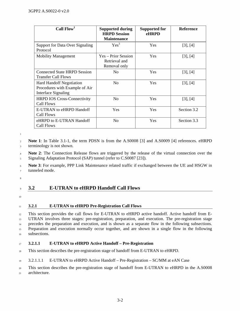
3GPP2 A.S0022-0 v2.0
3-2
Call Flow1 Supported during HRPD Session Maintenance
Supported for eHRPD
Reference
Support for Data Over Signaling Protocol
Yes3 Yes [3], [4]
Mobility Management Yes – Prior Session Retrieval and Removal only
Yes [3], [4]
Connected State HRPD Session Transfer Call Flows
No Yes [3], [4]
Hard Handoff Negotiation Procedures with Example of Air Interface Signaling
No Yes [3], [4]
HRPD IOS Cross-Connectivity Call Flows
No Yes [3], [4]
E-UTRAN to eHRPD Handoff Call Flows
Yes Yes Section 3.2
eHRPD to E-UTRAN Handoff Call Flows
No Yes Section 3.3
1
Note 1: In Table 3.1-1, the term PDSN is from the A.S0008 [3] and A.S0009 [4] references. eHRPD 2
terminology is not shown. 3
Note 2: The Connection Release flows are triggered by the release of the virtual connection over the 4
Signaling Adaptation Protocol (SAP) tunnel (refer to C.S0087 [23]). 5
Note 3: For example, PPP Link Maintenance related traffic if exchanged between the UE and HSGW in 6
tunneled mode. 7
8
3.2 E-UTRAN to eHRPD Handoff Call Flows 9
10
3.2.1 E-UTRAN to eHRPD Pre-Registration Call Flows 11
This section provides the call flows for E-UTRAN to eHRPD active handoff. Active handoff from E-12
UTRAN involves three stages: pre-registration, preparation, and execution. The pre-registration stage 13
precedes the preparation and execution, and is shown as a separate flow in the following subsections. 14
Preparation and execution normally occur together, and are shown in a single flow in the following 15
subsections. 16
3.2.1.1 E-UTRAN to eHRPD Active Handoff – Pre-Registration 17
This section describes the pre-registration stage of handoff from E-UTRAN to eHRPD. 18
3.2.1.1.1 E-UTRAN to eHRPD Active Handoff – Pre-Registration – SC/MM at eAN Case 19
This section describes the pre-registration stage of handoff from E-UTRAN to eHRPD in the A.S0008 20
architecture. 21

3GPP2 A.S0022-0 v2.0
3-3
eAT E-UTRANeAN1/ePCF1
HSGW PCRFMME
HSS
eAN2/ePCF2
Tunneled messaging
Tunneled messaging
Tunneled messaging
Tunneled messaging
0. eAT registered in MME for an ongoing data session
1. E-UTRAN indicates to the eAT that it should pre-register.
2. A communication path is established between the eAT and eHRPD. An S101 tunnel is used between MME and eAN1.
5b. A12 Access-Request
5c. A12 Access-Accept
6b. A11-Registration-Reply
6a. A11-Registration-RequestTregreq
9. IP session maintenance with HSGW.
8c. eAN2/ePCF2 performs A13 HO with eAN1/ePCF1
8b. HRPD session maintenance with eAN2/ePCF2
7a. Authenticate and establish IP service contextbetween eAT and HSGW over default signaling flow.
7b. Authentication.
3. UATI-Request/Response (optional)
5a. Device Level Authentication
4. Session Configuration
10. Update policy info
7c. Obtain policy info
8a. HRPD session maintenance with eAN1/ePCF1
AN-AAA
1
Figure 3.2.1.1.1-1 E-UTRAN to eHRPD Pre-Registration – SC/MM at eAN Case 2
1. Assuming an existing radio connection on E-UTRAN (step 0), the E-UTRAN indicates to the eAT 3
that it should begin pre-registration with the eHRPD system. Refer to TS 23.402 [1]. 4
2. A communication path is established between the eAT and eHRPD. The eAT, E-UTRAN, and MME 5
support transparent eHRPD air interface signaling and PPP message transfer between the eAT and the 6

3GPP2 A.S0022-0 v2.0
3-4
MME. An S101 tunnel is used between the MME and the eAN. The MME then creates an S101 1
session with eAN1/ePCF1. 2
3. If the eAT does not have a UATI, or if the UATI needs to be changed, the eAT uses HRPD air 3
interface signaling to request and receive a UATI value. 4
4. The eAT and eAN1/ePCF1 then configure the HRPD session using HRPD signaling tunneled via 5
S101. Refer to C.S0087 [23]. 6
5. If device level authentication is required by the operator, the eAT and eAN1/ePCF1 establish a PPP 7
connection and exchange CHAP signaling. eAN1/ePCF1 uses A12 signaling to perform the device 8
level authentication as shown in steps 5b and 5c. 9
6. eAN1/ePCF1 and HSGW exchange A11 signaling messages to establish the main A10 connection. 10
The A11-Registration Request message contains the Tunnel Mode indication with the value set to ‘1’ 11
specifying that the access is occurring through the S101 tunnel. Based upon this indication the HSGW 12
does not perform binding establishment or update at the Packet Data Network Gateway (P-GW). If 13
the eAT requests additional service connections after the main A10 connection is established, 14
eAN1/ePCF1 may establish auxiliary A10 connections according to the request of the eAT. 15
7. Using the main A10 connection established in step 6, the eAT and HSGW exchange authentication 16
signaling as described in X.S0057 [25]. The HSGW can obtain policy information related to the user 17
from the Policy and Charging Rules Function (PCRF) as part of these procedures. Once 18
authentication is complete, the eAT and HSGW exchange signaling to build the IP service context 19
between themselves, including IP addresses, PDN connections, QoS information, Traffic Flow 20
Templates (TFTs), etc. Refer to X.S0057 [25] for details. 21
Steps 8-10 apply to session maintenance. 22
8. It may become necessary to modify the HRPD session configuration between the eAT and 23
eAN1/ePCF1 (step 8a). Or to establish an HRPD session with eAN2/ePCF2 as a result of moving 24
under the coverage area of a new eAN2/ePCF2 as shown in step 8b, for example. In which case, the 25
new eAN2/ePCF2 will perform an A13 dormant handoff procedure with the old eAN1/ePCF1 as 26
shown in step 8c. As part of the dormant handoff, the S101 tunnel is relocated to the new 27
eAN2/ePCF2. The HRPD session maintenance is accomplished by HRPD signaling exchanges 28
between the eAT and the eAN/ePCF via S101 tunneling. 29
9. If any bearer is added, modified, or deleted while the eAT is operating on E-UTRAN, similar changes 30
are made in the IP service context between the eAT and the HSGW. This is accomplished by 31
signaling those changes between the eAT and HSGW via S101 tunneling. 32
10. Depending on what IP session maintenance is done in step 9, the HSGW may need to update the 33
PCRF. 34
3.2.1.1.2 E-UTRAN to eHRPD Active Handoff – Pre-Registration – SC/MM at ePCF Case 35
This section describes the pre-registration stage of handoff from E-UTRAN to eHRPD in the A.S0009 36
architecture. 37
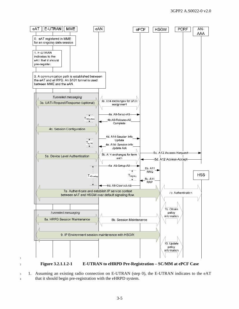
3GPP2 A.S0022-0 v2.0
3-5
1
Figure 3.2.1.1.2-1 E-UTRAN to eHRPD Pre-Registration – SC/MM at ePCF Case 2
1. Assuming an existing radio connection on E-UTRAN (step 0), the E-UTRAN indicates to the eAT 3
that it should begin pre-registration with the eHRPD system. 4

3GPP2 A.S0022-0 v2.0
3-6
2. A communication path is established between the eAT and eHRPD. The eAT, E-UTRAN, and MME 1
support transparent eHRPD air interface signaling and PPP message transfer between the eAT and 2
MME. An S101 tunnel is used between MME and the eAN. 3
3. If the eAT does not have a UATI, or if the UATI needs to be changed, the eAT uses HRPD air 4
interface signaling to request and receive a UATI value. This step includes the A14 signaling 5
exchanges between eAN and ePCF to assign an UATI to the eAT by ePCF as detailed in A.S0009 [4]. 6
4. (step 4a) The eAN sends an A9-Setup-A8 message to the ePCF to establish the main A8 connection. 7
(step 4b) The ePCF sends an A9-Release-A8 Complete message to the eAN containing session 8
information and requesting terminal authentication. (step 4c) The eAT and the eAN then configure 9
the HRPD session using HRPD signaling tunneled via S101. (step 4d) The eAN sends an A14-10
Session Information Update message to the ePCF to update the negotiated session information at the 11
ePCF. (step 4e) The ePCF responds with an A14-Session Information Update Ack message. 12
5. If device level authentication is required by the operator, the eAT and eAN/ePCF establish a PPP 13
connection and exchange CHAP signaling. The eAN and ePCF follow the A14 procedures specified 14
in A.S0009 [4] for terminal authentication, as shown in step 5b. The ePCF uses A12 signaling to 15
perform the device level authentication with the AN-AAA, as shown in steps 5c and 5d. 16
6. The eAN sends an A9-Setup-A8 message to establish the main A8 connection (step 6a), which 17
triggers the ePCF and HSGW A11 signaling exchange messages to establish the main A10 18
connection (steps 6b and 6c). The A11-Registration Request message contains the Tunnel Mode 19
indication with the value set to ‘1’ specifying that the access is occurring through the S101 tunnel. 20
Based upon this indication the HSGW does not perform binding establishment or update at the P-21
GW. Upon successful establishment of the A10 connection, the ePCF sends an A9-Connected-A8 22
message to the eAN to complete the establishment of the A8 connection (step 6d). If the eAT requests 23
additional service connections after the main A10 connection is established, eAN1/ePCF1 may 24
establish auxiliary A10 connections according to the request of the eAT. 25
7. Using the main A10 connection established in steps 6b/c, the eAT and HSGW exchange 26
authentication signaling as described in X.S0057 [25]. The HSGW can obtain policy information 27
related to the user from the PCRF as part of these procedures. Once authentication is complete, the 28
eAT and HSGW exchange signaling to build the IP service context between themselves, including IP 29
addresses, PDN connections, QoS information, TFTs, etc. Refer to X.S0057 [25] for details. 30
Step 8-10 apply to session maintenance. 31
8. It may become necessary to modify the HRPD session configuration between the eAT and the 32
eAN/ePCF. This may be necessary as a result of moving under the coverage area of a new eAN, for 33
example. This is accomplished by HRPD signaling exchanges between the eAT and the eAN via 34
S101 tunneling and corresponding IOS signaling between eAN and ePCF and between ePCF and 35
HSGW. 36
9. If any bearer is added, modified, or deleted while the eAT is operating on E-UTRAN, similar changes 37
are made in the IP service context between the eAT and the HSGW. This is accomplished by 38
signaling those changes between the eAT and HSGW via S101 tunneling. 39
10. Depending on what IP service context changes may be made in step 9, the HSGW may need to update 40
the PCRF. 41
3.2.2 E-UTRAN to eHRPD Active Handoff 42
43
3.2.2.1 E-UTRAN to eHRPD Active Handoff – Preparation and Execution – A8 Connected 44
This section describes the preparation and execution stages of handoff from E-UTRAN to eHRPD. This 45
scenario assumes that the handoff to eHRPD happens shortly after the pre-registration completion, 46
however before the eHRPD packet data session transitions to dormant state. 47
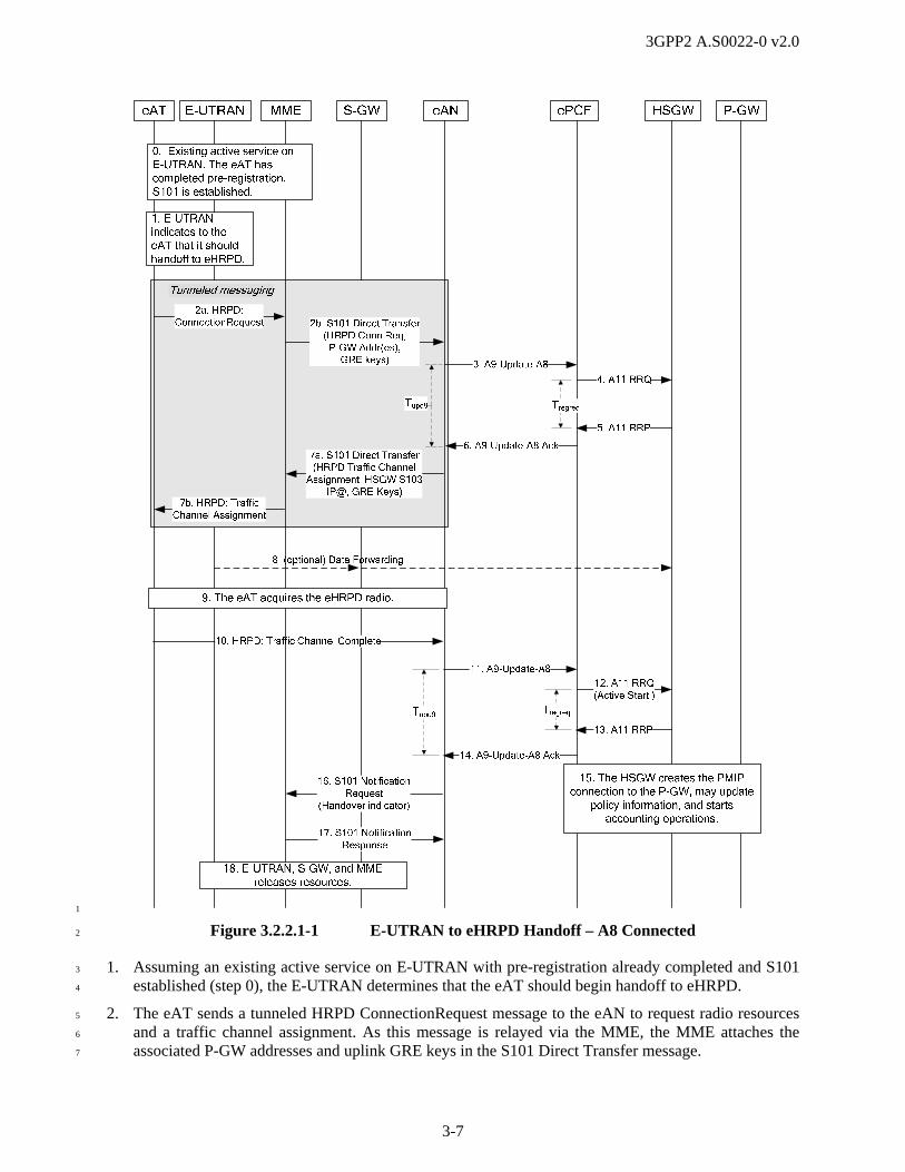
3GPP2 A.S0022-0 v2.0
3-7
1
Figure 3.2.2.1-1 E-UTRAN to eHRPD Handoff – A8 Connected 2
1. Assuming an existing active service on E-UTRAN with pre-registration already completed and S101 3
established (step 0), the E-UTRAN determines that the eAT should begin handoff to eHRPD. 4
2. The eAT sends a tunneled HRPD ConnectionRequest message to the eAN to request radio resources 5
and a traffic channel assignment. As this message is relayed via the MME, the MME attaches the 6
associated P-GW addresses and uplink GRE keys in the S101 Direct Transfer message. 7

3GPP2 A.S0022-0 v2.0
3-8
3. The eAN sends an A9-Update-A8 message to the ePCF containing the P-GW addresses and the 1
uplink GRE keys that were received in step 2. It also requests the data forwarding address for the 2
HSGW and a GRE key. The eAN starts timer Tupd9. 3
4. The ePCF sends an A11-Registration Request message to the HSGW containing the P-GW addresses, 4
the Tunnel Mode indication with the value set to ‘1’ and the uplink GRE keys. It also requests the 5
data forwarding address for the HSGW and GRE keys. The ePCF starts timer Tregreq. 6
5. The HSGW replies with an A11-Registration Reply message. If data forwarding is supported, the data 7
forwarding address for the HSGW and the GRE keys are included in the message. Upon receipt of 8
this message, the ePCF stops timer Tregreq. 9
6. The ePCF sends an A9-Update-A8 Ack message to the eAN containing the data forwarding address 10
for the HSGW and GRE keys, if provided in step 5. Upon receipt of this message, the eAN stops 11
timer Tupd9. 12
7. The eAN allocates the necessary radio resources and sends a tunneled HRPD 13
TrafficChannelAssignment (TCA) message to the eAT. IEs in the S101 message contain the data 14
forwarding address for the HSGW and GRE keys, if provided in step 6. The TCA is sent via an S101 15
Direct Transfer message to the MME along with the GRE keys and IP address for tunneling downlink 16
data from the Serving Gateway (S-GW) to the HSGW (step 7a), and is then relayed from the MME 17
via the E-UTRAN to the eAT (step 7b). 18
8. If data forwarding is to be used, the E-UTRAN begins to forward data packets via the S-GW to the 19
HSGW using the HSGW IP address and GRE keys. 20
9. The eAT acquires the eHRPD system. 21
10. The eAT sends an HRPD TrafficChannelComplete (TCC) message to the eAN. 22
11. Upon receiving the TCC, the eAN sends an A9-Update-A8 message containing a Handoff Execution 23
indication set to ‘1’ to the ePCF, and starts timer Tupd9. 24
12. The ePCF sends an A11-Registration Request message containing an Active Start Airlink Record to 25
the HSGW and the tunnel mode indication with the value set to ‘0’, and starts timer Tregreq. 26
13. The HSGW acknowledges with an A11-Registration Reply message. Upon receipt of this message, 27
the ePCF stops timer Tregreq. 28
14. The ePCF acknowledges with an A9-Update-A8 Ack message. Upon receipt of this message, the 29
eAN stops timer Tupd9. 30
15. The HSGW creates the Proxy Mobile Internet Protocol (PMIP) binding and completes any other 31
necessary procedures. Refer to X.S0057 [25] for details. This step is triggered by step 12 and happens 32
in parallel with step 13. 33
16. The eAN sends an S101 Notification Request message to indicate handoff completion to the MME. 34
17. The MME responds with an S101 Notification Response message to the eAN. 35
18. The E-UTRAN, MME, and S-GW release resources, including the PMIP tunnel from the S-GW to 36
the P-GW. 37
3.2.2.2 E-UTRAN to eHRPD Active Handoff – Preparation and Execution – A8 Disconnected 38
This section describes the preparation and execution stages of handoff from E-UTRAN to eHRPD. This 39
scenario assumes that the handoff to eHRPD happens after the pre-registration completion and the 40
eHRPD packet data session transition to dormant state. 41

3GPP2 A.S0022-0 v2.0
3-9
eAT E-UTRAN S-GW eAN HSGW PCRF P-GW
12. A11 RRQ(Active Start)
13. A11 RRP
8. (optional) Data Forwarding
MME ePCF
11. A9-Update-A8
14. A9-Update-A8 Ack
15. The HSGW creates the PMIP connection to the P-GW, may update policy information,
and starts accounting operations.
2b. S101 Direct Transfer (HRPD Conn Req,
P-GW Addr(es), GRE keys)
2a. HRPD: ConnectionRequest
1. E-UTRAN indicates to the eAT that it should handoff to eHRPD.
16. S101 Notification Request (Handover
indicator)
17. S101 Notification Response
18. E-UTRAN, S-GW, and MME releases resources.
0. Existing active service on E-UTRAN. The eAT has completed pre-registration. S101 is established.
10. HRPD: Traffic Channel Complete
7b. HRPD: TrafficChannel Assignment
7a. S101 Direct Transfer (HRPD Traffic Channel
Assignment, HSGW
S103 IP@, GRE Keys)
TregreqTupd9
TA8-setup
3a. A9-Setup-A8
TA8-setup
4. A11 RRQ
5. A11 RRP
Tregreq
6. A9-Connect-A8
3b. A9-Release-A8 Complete
3c. A9-Setup-A8
9. The eAT acquires the eHRPD radio.
1
Figure 3.2.2.2-1 E-UTRAN to eHRPD Handoff – A8 Disconnected 2
1. Assuming an existing active service on E-UTRAN with pre-registration already completed and S101 3
established (step 0), the E-UTRAN determines that the eAT should begin handoff to eHRPD. 4
3GPP2 A.S0022-0 v2.0
3-10
2. The eAT sends a tunneled HRPD ConnectionRequest message to the eAN to request radio resources 1
and a traffic channel assignment. As this message is relayed via the MME, the MME attaches the 2
associated P-GW addresses and uplink GRE keys in the S101 Direct Transfer message. 3
3. Steps 3.a and 3.b only apply to the A.S0009 architecture. Step 3.c is common for both architectures. 4
3.a. The eAN sends an A9-Setup-A8 message to the ePCF with the Data Ready Indicator (DRI) set to 1, 5
containing the P-GW addresses and the uplink GRE keys that were received in step 2. It also requests 6
the data forwarding address for the HSGW and GRE keys. The Session Information Required field of 7
the HRPD A9 Indicators IE in this message is set to ‘1’ to get Session Information Record from the 8
ePCF. The message includes the single connection information. The eAN starts timer TA8setup. 9
3.b. The ePCF determines that multiple A8 connections are required. The ePCF sends an A9-Release-A8 10
Complete message to the eAN with the SSIRs and the cause value set to “Multi-connection required”. 11
Upon receipt of this message, the eAN stops timer TA8setup. 12
3.c. The eAN sends an A9-Setup-A8 message to the ePCF with the DRI set to 1 and including multiple 13
GRE keys for the A8 tunnels establishment. The message also contains the P-GW addresses and the 14
uplink GRE keys that were received in step 2. The eAN starts timer TA8setup. 15
4. The ePCF sends an A11-Registration Request message to the HSGW containing the P-GW addresses, 16
the Tunnel Mode indication with the value set to ‘1’ and the uplink GRE keys. It also requests the 17
data forwarding address for the HSGW and GRE keys. The ePCF starts timer Tregreq. 18
5. The HSGW replies with an A11-Registration Reply message containing the data forwarding address 19
for the HSGW and GRE keys. Upon receipt of this message, the ePCF stops timer Tregreq. 20
6. The ePCF sends an A9-Connect-A8 message to the eAN containing the data forwarding address for 21
the HSGW and GRE keys. Upon receipt of this message, the eAN stops timer TA8setup. 22
7. Using the default A10 connection established during the pre-registration phase (refer to section 23
3.2.1.1), the eAN allocates the necessary radio resources and sends a tunneled HRPD 24
TrafficChannelAssignment (TCA) message to the eAT. IEs in the S101 message contain the data 25
forwarding address for the HSGW and GRE key, if provided in step 6. The TCA is sent via an S101 26
Direct Transfer message to the MME along with the GRE keys and IP address for tunneling downlink 27
data from the S-GW to the HSGW (step 7a), and is then relayed from the MME via the E-UTRAN to 28
the eAT (step 7b). 29
8. If data forwarding is to be used, the E-UTRAN begins to forward data packets via the S-GW to the 30
HSGW using the HSGW IP address and GRE key. 31
9. The eAT acquires the eHRPD radio interface. 32
10. The eAT sends an HRPD TrafficChannelComplete (TCC) message to the eAN. 33
11. Upon receiving the TCC, the eAN sends an A9-Update-A8 message containing a Handoff Execution 34
indication set to ‘1’ to the ePCF, and starts timer Tupd9. 35
12. The ePCF sends an A11-Registration Request message containing an Active Start Airlink Record to 36
the HSGW and the Tunnel Mode indication with the value set to ‘0’, and starts timer Tregreq. 37
13. The HSGW acknowledges with an A11-Registration Reply message. Upon receipt of this message, 38
the ePCF stops timer Tregreq. 39
14. The ePCF acknowledges with an A9-Update-A8 Ack message. Upon receipt of this message, the 40
eAN stops timer Tupd9. 41
15. The HSGW creates the PMIP binding and completes any other necessary procedures. Refer to 42
X.S0057 [25] for details. This step is triggered by step 12 and happens in parallel with step 13. 43
16. The eAN sends an S101 Notification Request message to indicate handoff completion to the MME. 44
3GPP2 A.S0022-0 v2.0
3-11
17. The MME responds with an S101 Notification Response message to the eAN. 1
18. The E-UTRAN, MME, and S-GW release resources, including the PMIP tunnel from the S-GW to 2
the P-GW. 3
3.2.2.3 E-UTRAN to eHRPD Active Handoff – Preparation and Execution – with Handover 4
between eANs 5
This section describes the preparation and execution stages of handoff from E-UTRAN to eHRPD. This 6
scenario assumes that eHRPD inter-eAN session transfer happens during the active handoff. The target 7
eAN, via the A16 interface session transfer, receives the session information that was configured at the 8
source eAN during pre-registration. 9
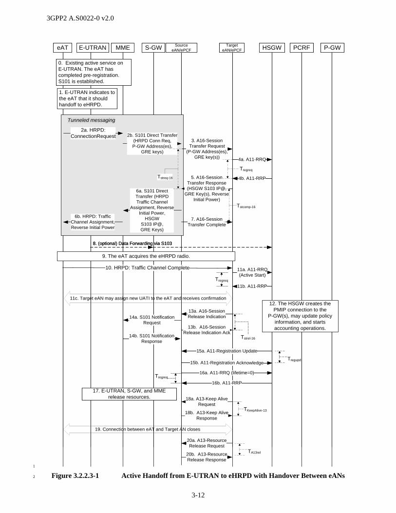
3GPP2 A.S0022-0 v2.0
3-12
eAT E-UTRAN S-GW Source eAN/ePCF HSGW PCRF P-GW
11a. A11 RRQ(Active Start)
11b. A11 RRP
8. (optional) Data Forwarding via S103
MME Target eAN/ePCF
2b. S101 Direct Transfer (HRPD Conn Req, P-GW Address(es),
GRE keys)
2a. HRPD: ConnectionRequest
1. E-UTRAN indicates to the eAT that it should handoff to eHRPD.
14b. S101 Notification Response
17. E-UTRAN, S-GW, and MME release resources.
0. Existing active service on E-UTRAN. The eAT has completed pre-registration. S101 is established.
Tunneled messaging
6b. HRPD: TrafficChannel Assignment, Reverse Initial Power
6a. S101 Direct Transfer (HRPDTraffic Channel
Assignment, Reverse Initial Power,
HSGW S103 IP@, GRE Keys)
Tregreq
4a. A11 RRQ
4b. A11 RRP5. A16-Session Transfer Response (HSGW S103 IP@,
GRE Key(s), Reverse Initial Power)
3. A16- Session Transfer Request
(P-GW Address(es), GRE key(s))
7. A16- Session Transfer Complete
13a. A16-Session Release Indication
13b. A16-Session Release Indication Ack
Tstreq-16
Tstrel-16
16a. A11 RRQ (lifetime=0)
16b. A11 RRP
Tregreq
15a. A11-Registration Update
15b. A11-Registration AcknowledgeTregupd
18a. A13-Keep Alive Request
eAT E-UTRAN S-GW Source eAN/ePCF HSGW PCRF P-GW
11a. A11-RRQ(Active Start)
11b. A11-RRP
8. (optional) Data Forwarding via S103
MME Target eAN/ePCF
12. The HSGW creates the PMIP connection to the
P-GW(s), may update policy information, and starts accounting operations.
2b. S101 Direct Transfer (HRPD Conn Req, P-GW Address(es),
GRE keys)
2a. HRPD: ConnectionRequest
1. E-UTRAN indicates to the eAT that it should handoff to eHRPD.
14a. S101 Notification Request
14b. S101 Notification Response
17. E-UTRAN, S-GW, and MME release resources.
0. Existing active service on E-UTRAN. The eAT has completed pre-registration. S101 is established.
Tunneled messaging
10. HRPD: Traffic Channel Complete
6b. HRPD: TrafficChannel Assignment, Reverse Initial Power
6a. S101 Direct Transfer (HRPDTraffic Channel
Assignment, Reverse Initial Power,
HSGW S103 IP@, GRE Keys)
Tregreq
4a. A11-RRQ
4b. A11-RRP
9. The eAT acquires the eHRPD radio.
5. A16-Session Transfer Response (HSGW S103 IP@,
GRE Key(s), Reverse Initial Power)
3. A16-Session Transfer Request
(P-GW Address(es), GRE key(s))
7. A16-Session Transfer Complete
13a. A16-Session Release Indication
13b. A16-Session Release Indication Ack
Tstreq-16
Tstrel-16
Tstcomp-16
Tregreq
16a. A11-RRQ (lifetime=0)
16b. A11-RRP
Tregreq
15a. A11-Registration Update
15b. A11-Registration AcknowledgeTregupd
18b. A13-Keep Alive Response
11c. Target eAN may assign new UATI to the eAT and receives confirmation
20a. A13-Resource Release Request
20b. A13-Resource Release Response
TA13rel
19. Connection between eAT and Target AN closes
TKeepAlive-13
1
Figure 3.2.2.3-1 Active Handoff from E-UTRAN to eHRPD with Handover Between eANs 2

3GPP2 A.S0022-0 v2.0
3-13
1. Assuming an existing active service on E-UTRAN with pre-registration already completed and S101 1
established (step 0), the E-UTRAN determines that the eAT should begin handoff to eHRPD. 2
2. The eAT sends a tunneled HRPD ConnectionRequest message to the source eAN/ePCF to request 3
radio resources and a traffic channel assignment. As this message is relayed via the MME, the MME 4
attaches the associated P-GW address(es) and uplink GRE key(s) in the S101 Direct Transfer 5
message. 6
3. Based on the received RouteUpdate message, the source eAN/ePCF determines the qualified target 7
sector belongs to the target eAN/ePCF. The source eAN/ePCF sends an A16-Session Transfer 8
Request message to the target eAN/ePCF to request session transfer for the AT. The source 9
eAN/ePCF shall include the associated P-GW address(es) and uplink GRE key(s) in the A16-Session 10
Transfer Request message. The source eAN/ePCF starts timer Tstreq-16. 11
4. a. The target eAN/ePCF sends an A11-Registration Request message to the HSGW containing the P-12
GW address(es) and uplink GRE key(s), the Tunnel Mode indication with the value set to ‘1’. It also 13
requests the data forwarding address for the HSGW and GRE key(s). The target eAN/ePCF starts 14
timer Tregreq. 15
b. The HSGW replies with an A11-Registration Reply message. If data forwarding is supported, the 16
data forwarding address for the HSGW and the GRE keys are included in the message. Upon receipt 17
of this message, the target eAN/ePCF stops timer Tregreq. 18
5. The target eAN/ePCF accepts the hard handoff request by sending an A16-Session Transfer Response 19
message to the source eAN. The message also includes the data forwarding address for the HSGW, 20
GRE key(s), if data forwarding is supported by the T-HSGW. The message also includes the Reverse 21
Initial Power parameters. The target eAN/ePCF starts timer Tstcomp-16. 22
6. Upon receipt of the A16-Session Transfer Response message, the source eAN/ePCF sends the 23
encapsulated TCA message to the MME. The TCA message is sent via an S101 Direct Transfer 24
message to the MME. The S101 Direct Transfer message includes the GRE key(s) and IP address for 25
tunneling downlink data from the S-GW to the HSGW if those values were received in the A16-26
Session Transfer Response message. The message also includes the Reverse Initial Power parameters. 27
The TCA is then relayed from the MME via the E-UTRAN to the eAT (step 6b). If an 28
HRPDOpenLoopParameters IE was received as part of the A16-Session Transfer Response message, 29
the source eAN/ePCF sends that over S101 before sending the TCA message. 30
7. The source eAN/ePCF sends an A16-Session Transfer Complete message to the target eAN/ePCF. 31
Upon receipt of the A16-Session Transfer Complete message, the target AN stops timer Tstcomp-16. 32
This step may occur any time after step 5. 33
8. If data forwarding is to be used, the E-UTRAN begins to forward data packets via the S-GW to the 34
HSGW using the HSGW IP address and GRE key(s). 35
9. The eAT acquires the eHRPD radio interface on the target eAN/ePCF. 36
10. The eAT sends an HRPD TrafficChannelComplete (TCC) message to the eAN/ePCF. 37
11. a. Upon receiving the TCC, the target eAN/ePCF sends an A11-Registration Request message 38
containing an Active Start Airlink Record to the HSGW and the Tunnel Mode indication with the 39
value set to ‘0’, and starts timer Tregreq. 40
b. The HSGW acknowledges with an A11-Registration Reply message. Upon receipt of this 41
message, the target eAN/ePCF stops timer Tregreq. 42
c. If the source eAN and the target eAN are in different subnet, then the target eAN assigns a new 43
UATI to the eAT and receives confirmation from the eAT that the new UATI is now in use. 44
12. The HSGW creates the PMIP binding and completes any other necessary procedures. Refer to 45
X.S0057 [25] for details. This step is triggered by step 11 and may occur any time after step 11a. 46
3GPP2 A.S0022-0 v2.0
3-14
13. a. After the target eAN/ePCF has acquired the UE and is assured that access to the system by the UE 1
would be directed to the target eAN/ePCF, it sends an A16-Session Release Indication message to the 2
source eAN/ePCF. The target eAN starts timer Tstrel-16. 3
b. The source eAN/ePCF sends an A16-Session Release Indication Ack message to the target 4
eAN/ePCF. Upon receipt of the A16-Session Release Indication Ack message, the target eAN/ePCF 5
stops timer Tstrel-16. 6
14. a. Upon receipt of the A16-Session Release Indication message, the source eAN/ePCF sends an S101 7
Notification Request message to indicate handoff completion to the MME. 8
b. The MME responds with an S101 Notification Response message to the source eAN/ePCF. 9
15. a. The HSGW initiates closure of the A10 connections with the source eAN/ePCF by sending an 10
A11-Registration Update message. The HSGW starts timer Tregupd. 11
b. The source eAN/ePCF responds with an A11-Registration Acknowledge message. The HSGW 12
stops timer Tregupd. 13
16. a. The source eAN/ePCF sends an A11-Registration Request message with Lifetime set to zero, to 14
the HSGW. The source eAN/ePCF starts timer Tregreq. 15
b. The HSGW sends an A11-Registration Reply message to the source eAN/ePCF. The source 16
eAN/ePCF closes the A10 connections for the eAT and stops timer Tregreq. 17
17. The E-UTRAN, MME, and S-GW release resources, including the bearer paths from the S-GW to the 18
P-GW. 19
18. a. The target eAN/ePCF may send an A13-Keep Alive Request message to the source eAN/ePCF 20
(assuming that the source eAN/ePCF is the eAN/ePCF that assigned the LCM_UATI) before TSClose-21
13 running at the source eAN/ePCF expires and starts timer TKeepAlive-13. 22
b. The source eAN/ePCF sends an A13-Keep Alive Response message to the target eAN/ePCF. The 23
target eAN/ePCF stops timer TKeepAlive-13. 24
19. The connection between the eAT and the target eAN closes. 25
20. a. After the connection between the eAT and the target eAN closes , the target eAN sends an A13-26
Resource Release Request message to the eAN identified by LCM_UATI in the A16-Session 27
Transfer Complete message. In this call flow, this eAN is assumed to be the source eAN. The target 28
eAN starts timer TA13rel. 29
b. Upon receipt of the A13-Resource Release Request message, the source eAN sends an A13-30
Resource Release Response message back to the target eAN. The source eAN may now re-assign the 31
UATI to another AT. Upon receipt of the A13-Resource Release Response message, the target eAN 32
stops timer TA13rel. 33
34
3.2.3 E-UTRAN to eHRPD Dormant Handoff 35
3.2.3.1 Dormant Handoff from E-UTRAN to eHRPD (Same eAN/ePCF) 36
This procedure is used in the case the eAT has a dormant HRPD packet data session in the eAN, either 37
through the pre-registration procedure or previous eHRPD attachment. 38
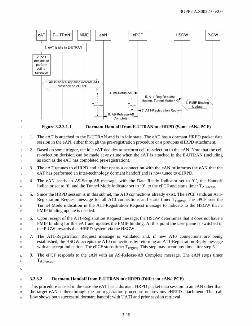
3GPP2 A.S0022-0 v2.0
3-15
eAT E-UTRAN eAN HSGWMME P-GWePCF
2. eAT decides to
perform cell re-
selection
Tregreq
4. A9-Setup-A8
8. A9-Release-A8Complete
6. PMIP Binding Update
5. A11-Reg Request (lifetime, Tunnel Mode = 0)
7. A11-Registration Reply
TA8-setup
1. eAT is idle in E-UTRAN
3. Air Interface signaling indicate eAT presence on eHRPD
1
Figure 3.2.3.1-1 Dormant Handoff from E-UTRAN to eHRPD (Same eAN/ePCF) 2
1. The eAT is attached to the E-UTRAN and is in idle state. The eAT has a dormant HRPD packet data 3
session in the eAN, either through the pre-registration procedure or a previous eHRPD attachment. 4
2. Based on some trigger, the idle eAT decides to perform cell re-selection to the eAN. Note that the cell 5
re-selection decision can be made at any time when the eAT is attached in the E-UTRAN (including 6
as soon as the eAT has completed pre-registration). 7
3. The eAT retunes to eHRPD and either opens a connection with the eAN or informs the eAN that the 8
eAT has performed an inter-technology dormant handoff and is now tuned to eHRPD. 9
4. The eAN sends an A9-Setup-A8 message, with the Data Ready Indicator set to ‘0’, the Handoff 10
Indicator set to ‘0’ and the Tunnel Mode indicator set to ‘0’, to the ePCF and starts timer TA8-setup. 11
5. Since the HRPD session is in this subnet, the A10 connections already exist. The ePCF sends an A11-12
Registration Request message for all A10 connections and starts timer Tregreq. The ePCF sets the 13
Tunnel Mode indication in the A11-Registration Request message to indicate to the HSGW that a 14
PMIP binding update is needed. 15
6. Upon receipt of the A11-Registration Request message, the HSGW determines that it does not have a 16
PMIP binding for this eAT and updates the PMIP binding. At this point the user plane is switched in 17
the P-GW towards the eHRPD system via the HSGW. 18
7. The A11-Registration Request message is validated and, if new A10 connections are being 19
established, the HSGW accepts the A10 connections by returning an A11-Registration Reply message 20
with an accept indication. The ePCF stops timer Tregreq. This step may occur any time after step 5. 21
8. The ePCF responds to the eAN with an A9-Release-A8 Complete message. The eAN stops timer 22
TA8-setup. 23
24
3.2.3.2 Dormant Handoff from E-UTRAN to eHRPD (Different eAN/ePCF) 25
This procedure is used in the case the eAT has a dormant HRPD packet data session in an eAN other than 26
the target eAN, either through the pre-registration procedure or previous eHRPD attachment. This call 27
flow shows both successful dormant handoff with UATI and prior session retrieval. 28

3GPP2 A.S0022-0 v2.0
3-16
eAT E-UTRANTarget
eAN/ePCFHSGWMME P-GW
Source eAN/ePCF
1. eAT is idle in E-UTRAN
2. eAT decides to
perform cell re-
selection
Tregreq
3. Initiate Session Establishment
10. PMIP Binding Update
14. A11-Registration Request (lifetime = 0)
15. A11-Registration Reply
13. A11-Registration Ack
12. A11-Registration Update
Tregupd
11. A11-Registration Reply
9. A11-Registration Request (non-zero lifetime, MEI, Tunnel Mode indication = 0)
7. Location Update Procedures
6. Complete Session Establishment
4. A13-Session Information Request
TA13req
TA13res
8. A13-Session Information Confirm
5. A13-Session Information Response
Tregreq
1
Figure 3.2.3.2-1 Dormant Handoff from E-UTRAN to eHRPD (Different eAN/ePCF) 2
1. The eAT is attached to the E-UTRAN and is in idle state. The eAT has a dormant HRPD packet data 3
session in the source eAN, either through the pre-registration procedure or previous eHRPD 4
attachment. 5
2. Based on some trigger, the idle eAT decides to perform cell re-selection to the eHRPD. Note that the 6
cell re-selection decision can be made at any time when the eAT is attached in the E-UTRAN 7
(including as soon as the eAT has completed pre-registration). 8
3. The eAT retunes to eHRPD and initiates HRPD session establishment with the target eAN. During 9
this procedure, the eAT sends the UATI of an existing HRPD session (if available). The UATI can be 10
used as an identifier for the existing HRPD session when the target eAN/ePCF attempts to retrieve the 11
existing HRPD session State Information from the source eAN/ePCF. 12
If the network is configured for prior session retrieval and the eAT has closed the session, the eAT 13
sends a UATIRequest message with a Random Access Terminal Identifier (RATI) to request that a 14
UATI be assigned to it. Upon receipt of the UATIRequest message, the target eAN/ePCF assigns the 15
new UATI to the eAT. The target eAN/ePCF may request Hardware ID from the eAT at any time 16
before step 4. The eAT performs the session establishment procedure by sending a Configuration 17
Request message including PriorSession Attribute to the target eAN/ePCF. 18
4. The target eAN/ePCF sends an A13-Session Information Request message to the source eAN/ePCF 19
to retrieve the context of the session. The A13-Session Information Request message shall include the 20

3GPP2 A.S0022-0 v2.0
3-17
received UATI, the Security Layer Packet and Sector ID. The message also contains the Hardware 1
ID, if available. The target eAN/ePCF starts timer TA13req. 2
5. The source eAN/ePCF sends an A13-Session Information Response message to the target eAN/ePCF 3
with the session information. The source eAN/ePCF starts timer TA13res. The target eAN/ePCF stops 4
timer TA13req. 5
6. The eAT and target eAN/ePCF complete HRPD session establishment. Depending on the state of the 6
eAT and the target eAN/ePCF, either an existing HRPD session may be re-established, or a new 7
HRPD session may be initiated if required. This step may be null if no further over-the-air signaling 8
is required. 9
7. If the target eAN supports the Location Update procedure, the target eAN updates the ANID in the 10
eAT using the Location Update procedure. The target eAN may also retrieve the PANID from the 11
eAT if necessary (e.g., the Session Configuration retrieved in step 5 indicates that the source AN does 12
not support the Location Update procedure). 13
8. The target eAN/ePCF informs the source eAN/ePCF that it now has control of the eAT via an A13-14
Session Information Confirm message. Upon receipt of the A13-Session Information Confirm 15
message the source AN deletes the associated AT HRPD session information. The source eAN/ePCF 16
stops timer TA13res. 17
9. Since the HRPD session was not previously in this subnet, the A10 connections are created to the 18
target ePCF. The target ePCF sends an A11-Registration Request message with a non-zero lifetime 19
and with the Tunnel Mode indication set to ‘0’ to cause the HSGW to move all A10 connections. The 20
A11-Registration Request message includes the Mobility Event Indicator (MEI) within the Critical 21
Vendor/Organization Specific Extension (CVSE). This message also includes a CVSE containing 22
Accounting Data (A10 Connection Setup Airlink Record). The target ePCF starts timer Tregreq. 23
10. Upon receipt of the A11-Registration Request message for HRPD session with nonzero lifetime timer 24
and with the Tunnel Mode indication set to ‘0’, the HSGW determines that it does not have a PMIP 25
binding for this eAT and updates the PMIP binding. At this point the user plane is switched in the P-26
GW towards the eHRPD system via the HSGW. 27
11. The HSGW sends an A11-Registration Reply message with an accept indication. This step may occur 28
any time after step 10. If the HSGW has data to send, it includes the Data Available Indicator within 29
the CVSE. If the subscriber has a Subscriber QoS Profile, the HSGW includes it in a Normal Vendor 30
Specific Extension (NVSE). The A10 connection binding information at the HSGW is updated to 31
point to the target ePCF. The target ePCF stops timer Tregreq. 32
12. The HSGW sends an A11-Registration Update message to initiate closure of the A10 connections for 33
the eAT with the source eAN/ePCF. The HSGW starts timer Tregupd. 34
13. The source eAN/ePCF acknowledges by sending an A11-Registration Ack message. The HSGW 35
stops timer Tregupd. 36
14. The source eAN/ePCF sends an A11-Registration Request message with lifetime=0 for all A10 37
connections. The source eAN/ePCF starts timer Tregreq. 38
15. The HSGW sends an A11-Registration Reply message to acknowledge the removal of the A10 39
connections by the source eAN/ePCF. The source eAN/ePCF stops timer Tregreq. 40
41
3.2.3.3 Dormant Handoff from E-UTRAN to eHRPD with Prior Session Removal 42
This procedure is used in the case the eAT has a dormant HRPD packet data session in an eAN other than 43
the target eAN, either through the pre-registration procedure or previous eHRPD attachment. This 44

3GPP2 A.S0022-0 v2.0
3-18
scenario shows prior session information removal in the case of expiration of the session retrieval timer 1
(i.e., timer TA13req) or operator’s policy. 2
eAT E-UTRANTarget
eAN/ePCFHSGWMME P-GW
Source eAN/ePCF
1. eAT is idle in E-UTRAN
2. eAT decides to
perform cell re-
selection
Tregreq 13. PMIP Binding Update
12. A11-Registration Request (non-zero lifetime, MEI, Tunnel Mode indication = 0)
14. A11-Registration Reply
4. Hardware ID Acquisition
3. UATI Assignment
7. A13-ResourceRelease Request
10. A11-Registration Reply
9. A11-Registration Request (lifetime = 0)Tregreq
11. Complete Session Establishment
8. A13-Resource Release Response
TA13rel
5. Configuration Request (Prior Session Attribute)
6. Configuration Response (Null)
3
Figure 3.2.3.3-1 Dormant Handoff from E-UTRAN to eHRPD with Prior Session Removal 4
1. The eAT is attached to the E-UTRAN and is in idle state. The eAT has a dormant HRPD packet data 5
session in the source eAN, either through the pre-registration procedure or previous eHRPD 6
attachment. 7
2. Based on some trigger, the idle eAT decides to perform cell re-selection to the eHRPD. Note that the 8
cell re-selection decision can be made at any time when the eAT is attached in the E-UTRAN 9
(including as soon as the eAT has completed pre-registration). 10
3. The eAT retunes to eHRPD and initiates HRPD session establishment with the target eAN/ePCF. The 11
AT has closed the session. The eAT sends a UATIRequest message with a Random Access Terminal 12
Identifier (RATI) to request that a UATI be assigned to it. Upon receipt of the UATIRequest 13
message, the target AN assigns the new UATI to the AT. 14
4. The target eAN/ePCF may request Hardware ID from the AT at any time before step 7. 15
5. The AT performs the session establishment procedure using the Configuration Request message, 16
including the Prior Session Attribute. If the target eAN/ePCF received the Prior Session Attribute in 17
the Configuration Request message, this call flow assumes that the target eAN/ePCF is configured to 18
release the prior session information on the source eAN/ePCF after receiving Prior Session Attribute. 19
6. The target eAN/ePCF sends the Configuration Response message with the Prior Session Attribute set 20
to Null. 21
3GPP2 A.S0022-0 v2.0
3-19
7. The target eAN/ePCF sends an A13-Resource Release Request message including the prior session 1
UATI as the session identifier to the source eAN/ePCF and starts timer TA13rel. In addition, the target 2
eAN/ePCF includes the Sector ID, Security Layer Packet and Hardware ID, if this information is 3
available. 4
8. When the source eAN/ePCF receives the A13-Resource Release Request message, it (depending on 5
operator’s policy) checks if requested session information is stored in the source eAN/ePCF, and 6
releases the session information related to the PriorSession Attribute if the Hardware ID and/or the 7
Security Layer Packet sent in the message verify the identity of the session information. The source 8
eAN/ePCF sends the A13-Resource Release Response message including the result for handling the 9
A13-Resource Release Request message to the target eAN/ePCF. Upon receipt of the A13-Resource 10
Release Response message, the target eAN/ePCF stops timer TA13rel. 11
9. The source eAN/ePCF may initiate closure of the A10 connections by sending an A11-Registration 12
Request message with Lifetime=0. The source eAN/ePCF starts timer Tregreq. 13
10. The HSGW send an A11-Registration Reply message to acknowledge the removal of the A10 14
connections by the source eAN/ePCF. Upon receipt of this message, the source eAN/ePCF stops 15
timer Tregreq. 16
11. The eAT and target eAN/ePCF complete HRPD session establishment. A new HRPD session may be 17
initiated if required. This step may occur any time after step 6. 18
12. The target ePCF sends an A11-Registration Request message with a non-zero lifetime and with the 19
Tunnel Mode indication set to ‘0’ to cause the HSGW to move all A10 connections. The A11-20
Registration Request message includes the MEI within the CVSE, a Tunnel Mode indication set to 21
‘0’, and a non-zero Lifetime. This message also includes a CVSE containing Accounting Data (A10 22
Connection Setup Airlink Record). The target eAN/ePCF starts timer Tregreq. 23
13. Upon receipt of the A11-Registration Request message for HRPD session with nonzero lifetime timer 24
and with the Tunnel Mode indication set to ‘0’, the HSGW determines that it does not have a PMIP 25
binding for this eAT and updates the PMIP binding. At this point the user plane is switched in the P-26
GW towards the eHRPD system via the HSGW. 27
14. The HSGW sends A11-Registration Reply message with an accept indication. This step may occur 28
any time after step 12. If the HSGW has data to send, it includes the Data Available Indicator within 29
the CVSE. If the subscriber has a Subscriber QoS Profile, the HSGW includes it in an NVSE. The 30
A10 connection binding information at the HSGW is updated to point to the target ePCF. Upon 31
receipt of this message, the target eAN/ePCF stops timer Tregreq. 32
33
3.3 eHRPD to E-UTRAN Handoff Call Flows 34
This section describes the call flows for dormant handoff from eHRPD to E-UTRAN. Note that dormant 35
handoff from eHRPD to E-UTRAN can occur when the eAT simply selects an E-UTRAN cell, tunes to 36
E-UTRAN, and performs normal E-UTRAN attach procedures. Dormant handoff can also be 37
accomplished using the procedure in the following subsection. 38
3.3.1 eHRPD to E-UTRAN Dormant Handoff Call Flow 39
This section describes the procedure for non-optimized dormant handoff from eHRPD to E-UTRAN. This 40
procedure assumes that the eAT did not previously attach to the E-UTRAN. Prior to the handoff, the eAT 41
is dormant on eHRPD. After the handoff, the eAT remains pre-registered in eHRPD (i.e., the eAT retains 42
its HRPD session). 43
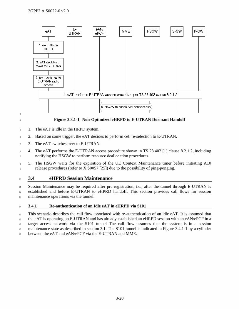
3GPP2 A.S0022-0 v2.0
3-20
1
Figure 3.3.1-1 Non-Optimized eHRPD to E-UTRAN Dormant Handoff 2
1. The eAT is idle in the HRPD system. 3
2. Based on some trigger, the eAT decides to perform cell re-selection to E-UTRAN. 4
3. The eAT switches over to E-UTRAN. 5
4. The eAT performs the E-UTRAN access procedure shown in TS 23.402 [1] clause 8.2.1.2, including 6
notifying the HSGW to perform resource deallocation procedures. 7
5. The HSGW waits for the expiration of the UE Context Maintenance timer before initiating A10 8
release procedures (refer to X.S0057 [25]) due to the possibility of ping-ponging. 9
3.4 eHPRD Session Maintenance 10
Session Maintenance may be required after pre-registration, i.e., after the tunnel through E-UTRAN is 11
established and before E-UTRAN to eHPRD handoff. This section provides call flows for session 12
maintenance operations via the tunnel. 13
3.4.1 Re-authentication of an Idle eAT in eHRPD via S101 14
This scenario describes the call flow associated with re-authentication of an idle eAT. It is assumed that 15
the eAT is operating on E-UTRAN and has already established an eHRPD session with an eAN/ePCF in a 16
target access network via the S101 tunnel The call flow assumes that the system is in a session 17
maintenance state as described in section 3.1. The S101 tunnel is indicated in Figure 3.4.1-1 by a cylinder 18
between the eAT and eAN/ePCF via the E-UTRAN and MME. 19

3GPP2 A.S0022-0 v2.0
3-21
4. CHAP Challenge - Response
3. PPP and LCP Negotiation
1. Re-Authentication Required
AN AAAeAT
5. A12 Access-Request
6. A12 Access-Accept
eAN/ePCF
7. CHAP - Authentication Success
2. AT Ready to ExchangeData on Access Stream
E-UTRANMM
E
1
Figure 3.4.1-1 Re-authentication of an Idle eAT in eHRPD via S101 2
1. The eAN/ePCF determines that re-authentication of an eAT is required and if virtual connection is not 3
open, initiates virtual connection establishment procedures with the eAT via the S101 tunnel. 4
2. The eAT indicates that it is ready to exchange data on the access stream (e.g., the flow control 5
protocol for the default packet application bound to the eAN is in the open state). 6
3. The eAT and the eAN/ePCF initiate PPP and LCP negotiations for access/terminal authentication via 7
the S101 tunnel. Refer to RFC 1661 [26]. This step is omitted when the eAN/ePCF and eAT keep the 8
PPP connection after initial access/terminal authentication. 9
4. The eAN/ePCF generates a random challenge and sends it to the eAT via the S101 tunnel in a CHAP 10
Challenge message in accordance with RFC 1994 [27]. 11
5. When the eAN/ePCF receives the CHAP response message from the eAT, it sends an Access-Request 12
message on the A12 interface to the AN-AAA which acts as a RADIUS server in accordance with 13
RFC 2865 [28]. 14
6. The AN-AAA looks up a password based on the User-name attribute in the Access-Request message 15
and if the access/terminal authentication passes (as specified in RFC 1994 [27] and RFC 2865 [28]), 16
the AN-AAA sends an Access-Accept message on the A12 interface in accordance with RFC 2865 17
[28]. The Access-Accept message contains a RADIUS attribute with Type set to 20 (Callback-Id), 18
which is set to the MN ID of the eAT. Refer to A.S0008 [3] and A.S0009 [4], Section 2.4.2, AN-19
AAA Support. 20
7. The eAN/ePCF returns an indication of CHAP access/terminal authentication success to the eAT via 21
S101 tunnel. Refer to RFC 1994 [27]. 22

3GPP2 A.S0022-0 v2.0
3-22
1
(This page intentionally left blank) 2
3
4
5
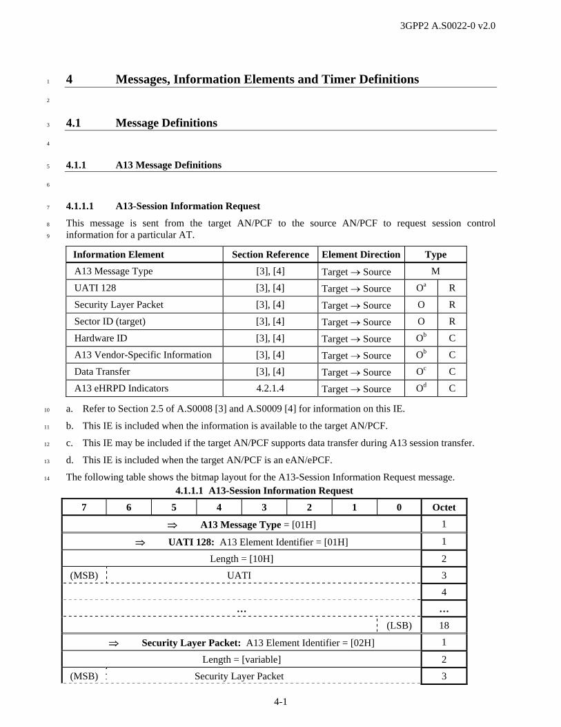
3GPP2 A.S0022-0 v2.0
4-1
4 Messages, Information Elements and Timer Definitions 1
2
4.1 Message Definitions 3
4
4.1.1 A13 Message Definitions 5
6
4.1.1.1 A13-Session Information Request 7
This message is sent from the target AN/PCF to the source AN/PCF to request session control 8
information for a particular AT. 9
Information Element Section Reference Element Direction Type
A13 Message Type [3], [4] Target Source M
UATI 128 [3], [4] Target Source Oa R
Security Layer Packet [3], [4] Target Source O R
Sector ID (target) [3], [4] Target Source O R
Hardware ID [3], [4] Target Source Ob C
A13 Vendor-Specific Information [3], [4] Target Source Ob C
Data Transfer [3], [4] Target Source Oc C
A13 eHRPD Indicators 4.2.1.4 Target Source Od C
a. Refer to Section 2.5 of A.S0008 [3] and A.S0009 [4] for information on this IE. 10
b. This IE is included when the information is available to the target AN/PCF. 11
c. This IE may be included if the target AN/PCF supports data transfer during A13 session transfer. 12
d. This IE is included when the target AN/PCF is an eAN/ePCF. 13
The following table shows the bitmap layout for the A13-Session Information Request message. 14
4.1.1.1 A13-Session Information Request
7 6 5 4 3 2 1 0 Octet
A13 Message Type = [01H] 1
UATI 128: A13 Element Identifier = [01H] 1
Length = [10H] 2
(MSB) UATI 3
4
… …
(LSB) 18
Security Layer Packet: A13 Element Identifier = [02H] 1
Length = [variable] 2
(MSB) Security Layer Packet 3
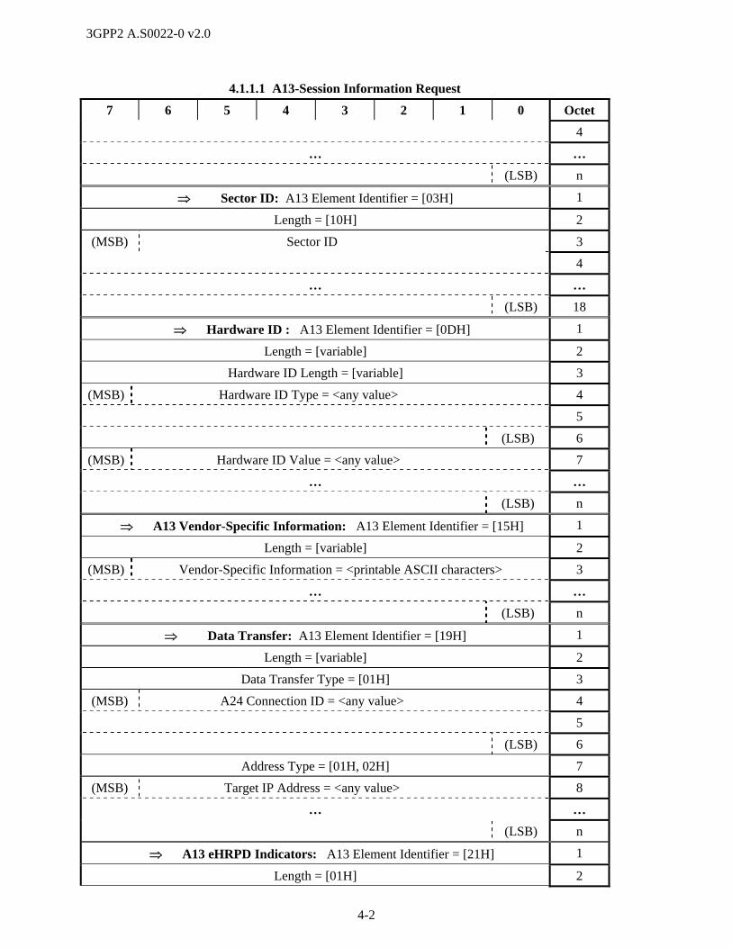
3GPP2 A.S0022-0 v2.0
4-2
4.1.1.1 A13-Session Information Request
7 6 5 4 3 2 1 0 Octet
4
… …
(LSB) n
Sector ID: A13 Element Identifier = [03H] 1
Length = [10H] 2
(MSB) Sector ID 3
4
… …
(LSB) 18
Hardware ID : A13 Element Identifier = [0DH] 1
Length = [variable] 2
Hardware ID Length = [variable] 3
(MSB) Hardware ID Type = <any value> 4
5
(LSB) 6
(MSB) Hardware ID Value = <any value> 7
… …
(LSB) n
A13 Vendor-Specific Information: A13 Element Identifier = [15H] 1
Length = [variable] 2
(MSB) Vendor-Specific Information = <printable ASCII characters> 3
… …
(LSB) n
Data Transfer: A13 Element Identifier = [19H] 1
Length = [variable] 2
Data Transfer Type = [01H] 3
(MSB) A24 Connection ID = <any value> 4
5
(LSB) 6
Address Type = [01H, 02H] 7
(MSB) Target IP Address = <any value> 8
… …
(LSB) n
A13 eHRPD Indicators: A13 Element Identifier = [21H] 1
Length = [01H] 2
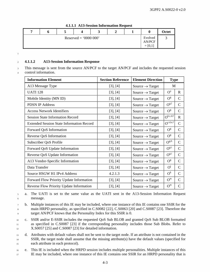
3GPP2 A.S0022-0 v2.0
4-3
4.1.1.1 A13-Session Information Request
7 6 5 4 3 2 1 0 Octet
Reserved = ‘0000 000’ Evolved AN/PCF = [0,1]
3
1
4.1.1.2 A13-Session Information Response 2
This message is sent from the source AN/PCF to the target AN/PCF and includes the requested session 3
control information. 4
Information Element Section Reference Element Direction Type
A13 Message Type [3], [4] Source Target M
UATI 128 [3], [4] Source Target Oa R
Mobile Identity (MN ID) [3], [4] Source Target Og C
PDSN IP Address [3], [4] Source Target Og,l C
Access Network Identifiers [3], [4] Source Target Og C
Session State Information Record [3], [4] Source Target Ob,c,d,f R
Extended Session State Information Record [3], [4] Source Target Oc,d,e,f C
Forward QoS Information [3], [4] Source Target Og C
Reverse QoS Information [3], [4] Source Target Og C
Subscriber QoS Profile [3], [4] Source Target Og,h C
Forward QoS Update Information [3], [4] Source Target Og,i C
Reverse QoS Update Information [3], [4] Source Target Og,i C
A13 Vendor-Specific Information [3], [4] Source Target Og C
Data Transfer [3], [4] Source Target Oj C
Source HSGW H1 IPv4 Address 4.2.1.3 Source Target Ok C
Forward Flow Priority Update Information [3], [4] Source Target Om C
Reverse Flow Priority Update Information [3], [4] Source Target Om C
a. The UATI is set to the same value as the UATI sent in the A13-Session Information Request 5
message. 6
b. Multiple instances of this IE may be included, where one instance of this IE contains one SSIR for the 7
main HRPD personality, as specified in C.S0082 [22], C.S0063 [20] and C.S0087 [23]. Therefore the 8
target AN/PCF knows that the Personality Index for this SSIR is 0. 9
c. SSIR and/or E-SSIR includes the requested QoS Sub BLOB and granted QoS Sub BLOB formatted 10
as specified in C.S0087 [23] if the corresponding personality includes those Sub Blobs. Refer to 11
X.S0057 [25] and C.S0087 [23] for detailed information. 12
d. Attributes with default values shall not be sent to the target node. If an attribute is not contained in the 13
SSIR, the target node shall assume that the missing attribute(s) have the default values (specified for 14
each attribute in each protocol). 15
e. This IE is included when the HRPD session includes multiple personalities. Multiple instances of this 16
IE may be included, where one instance of this IE contains one SSIR for an HRPD personality that is 17

3GPP2 A.S0022-0 v2.0
4-4
not the main personality, as specified in C.S0087 [23]. Multiple instances of this IE shall be sorted in 1
order of increasing personality index. 2
f. SSIRs of protocol types with HardLink subtype shall not be sent to the target node unless specified 3
otherwise. SSIRs of Session Configuration Protocol Types may be sent even if the subtype is set to 4
HardLink. 5
g. This IE is included if the information is available at the source AN/PCF. 6
h. Subject to configuration4, this IE is included if the information is available at the source AN/PCF. If 7
the target AN/PCF subsequently receives this information from the PDSN, then the information 8
received from the PDSN takes precedence. 9
i. This IE is included to convey the PDSN updated QoS of one or more IP flows in the specified 10
direction. Multiple instances of this IE may be included, where one instance of this IE contains all of 11
the PDSN updated QoS for a given personality. The target AN/PCF shall store the updated QoS lists 12
received from the PDSN and use them to grant the QoS irrespective of the contents of the subscriber 13
QoS Profile. 14
j. This IE may be included if the target AN/PCF support data transfer during session transfer (as 15
indicated in the A13-Session Information Request message) and the source AN/PCF has data to send. 16
k. This IE is included when the source eAN/ePCF and the target eAN/ePCF are connected to HSGWs 17
the ProtocolID indicates that this is an HRPD session for an eAT operating in evolved mode (refer to 18
C.S0087 [23]) and the information is available at the source AN/PCF. 19
l. The target eAN/ePCF can inspect the SSIRs/ESSIRs sent to it to determine whether the AT is 20
operating as an eAT, and thus know that the PDSN address provided is actually an HSGW address. 21
Otherwise, the target eAN/ePCF shall operate in legacy mode. 22
m. This IE is included to convey the HSGW updated flow priority for one or more IP flows in the 23
specified direction. 24
The following table shows the bitmap layout for the A13-Session Information Response message. 25
4.1.1.2 A13-Session Information Response
7 6 5 4 3 2 1 0 Octet
A13 Message Type = [04H] 1
UATI 128: A13 Element Identifier = [01H] 1
Length = [10H] 2
(MSB) UATI 3
4
… …
(LSB) 18
Mobile Identity (MN ID): A13 Element Identifier = [05H] 1
Length = [06H - 08H] (10 - 15 digits) 2
4 This specification calls for this information to be sent from the PDSN (via the target PCF) to the target AN. However in certain configurations outside the scope of this specification, this information may be sent from the source AN in the A13-Session Information Response message instead. This information should not be sent over both A11 and A13.

3GPP2 A.S0022-0 v2.0
4-5
4.1.1.2 A13-Session Information Response
7 6 5 4 3 2 1 0 Octet
Identity Digit 1 = [0H-9H] (BCD) Odd/even Indicator = [1,0]
Type of Identity = [110] (MN ID)
3
Identity Digit 3 = [0H-9H] (BCD) Identity Digit 2 = [0H-9H] (BCD) 4
… … …
Identity Digit N+1 = [0H-9H] (BCD) Identity Digit N = [0H-9H] (BCD) n
= [1111] (if even number of digits) Identity Digit N+2 = [0H-9H] (BCD) n+1
PDSN IP Address: A13 Element Identifier = [06H] 1
Length = [04H] 2
(MSB) PDSN IP Address 3
4
5
(LSB) 6
Access Network Identifiers: A13 Element Identifier = [07H] 1
Type = 01H 2
Length = [05H] 3
Reserved (MSB) SID 4
(LSB) 5
(MSB) NID 6
(LSB) 7
PZID 8
Session State Information Record: A13 Element Identifier = [08H] 1
(MSB) Length = [variable] 2
(LSB) 3
(MSB) Session State Information Record 4
… …
(LSB) n
Extended Session State Information Record: A13 Element Identifier = [09H] 1
(MSB) Length = [variable] 2
(LSB) 3
Reserved = [0000] Personality Index 4
(MSB) Session State Information Record 5
… …
(LSB) n
Forward QoS Information: A13 Element Identifier = [0AH] 1
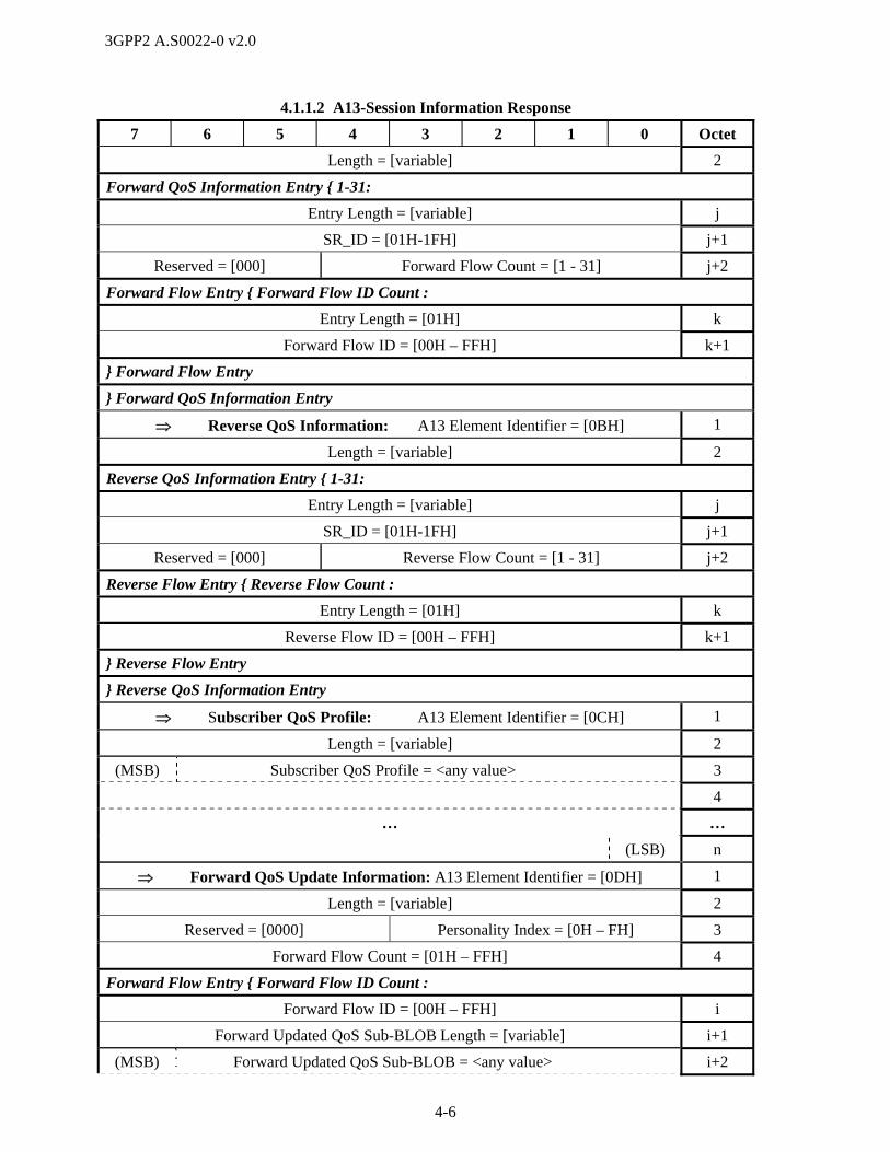
3GPP2 A.S0022-0 v2.0
4-6
4.1.1.2 A13-Session Information Response
7 6 5 4 3 2 1 0 Octet
Length = [variable] 2
Forward QoS Information Entry { 1-31:
Entry Length = [variable] j
SR_ID = [01H-1FH] j+1
Reserved = [000] Forward Flow Count = [1 - 31] j+2
Forward Flow Entry { Forward Flow ID Count :
Entry Length = [01H] k
Forward Flow ID = [00H – FFH] k+1
} Forward Flow Entry
} Forward QoS Information Entry
Reverse QoS Information: A13 Element Identifier = [0BH] 1
Length = [variable] 2
Reverse QoS Information Entry { 1-31:
Entry Length = [variable] j
SR_ID = [01H-1FH] j+1
Reserved = [000] Reverse Flow Count = [1 - 31] j+2
Reverse Flow Entry { Reverse Flow Count :
Entry Length = [01H] k
Reverse Flow ID = [00H – FFH] k+1
} Reverse Flow Entry
} Reverse QoS Information Entry
Subscriber QoS Profile: A13 Element Identifier = [0CH] 1
Length = [variable] 2
(MSB) Subscriber QoS Profile = <any value> 3
4
… …
(LSB) n
Forward QoS Update Information: A13 Element Identifier = [0DH] 1
Length = [variable] 2
Reserved = [0000] Personality Index = [0H – FH] 3
Forward Flow Count = [01H – FFH] 4
Forward Flow Entry { Forward Flow ID Count :
Forward Flow ID = [00H – FFH] i
Forward Updated QoS Sub-BLOB Length = [variable] i+1
(MSB) Forward Updated QoS Sub-BLOB = <any value> i+2
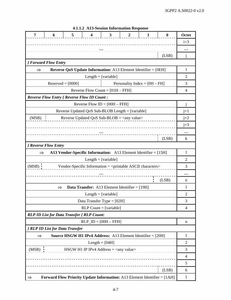
3GPP2 A.S0022-0 v2.0
4-7
4.1.1.2 A13-Session Information Response
7 6 5 4 3 2 1 0 Octet
i+3
… …
(LSB) j
} Forward Flow Entry
Reverse QoS Update Information: A13 Element Identifier = [0EH] 1
Length = [variable] 2
Reserved = [0000] Personality Index = [0H – FH] 3
Reverse Flow Count = [01H – FFH] 4
Reverse Flow Entry { Reverse Flow ID Count :
Reverse Flow ID = [00H – FFH] j
Reverse Updated QoS Sub-BLOB Length = [variable] j+1
(MSB) Reverse Updated QoS Sub-BLOB = <any value> j+2
j+3
… …
(LSB) k
} Reverse Flow Entry
A13 Vendor-Specific Information: A13 Element Identifier = [15H] 1
Length = [variable] 2
(MSB) Vendor-Specific Information = <printable ASCII characters> 3
… …
(LSB) n
Data Transfer: A13 Element Identifier = [19H] 1
Length = [variable] 2
Data Transfer Type = [02H] 3
RLP Count = [variable] 4
RLP ID List for Data Transfer { RLP Count:
RLP_ID = [00H – FFH] n
} RLP ID List for Data Transfer
Source HSGW H1 IPv4 Address: A13 Element Identifier = [20H] 1
Length = [04H] 2
(MSB) HSGW H1 IP IPv4 Address = <any value> 3
4
5
(LSB) 6
Forward Flow Priority Update Information: A13 Element Identifier = [1AH] 1

3GPP2 A.S0022-0 v2.0
4-8
4.1.1.2 A13-Session Information Response
7 6 5 4 3 2 1 0 Octet
Length = [variable] 2
Reserved = [0000] Personality Index = [0H – FH] 3
Forward Flow Count = [01H – FFH] 4
Forward Flow Entry { Forward Flow ID Count :
Forward Flow ID = [00H – FFH] i
Reserved = [0000] Forward Updated Flow Priority = [0H – FH]
i+1
} Forward Flow Entry
Reverse Flow Priority Update Information: A13 Element Identifier = [1BH] 1
Length = [variable] 2
Reserved = [0000] Personality Index = [0H – FH] 3
Reverse Flow Count = [01H – FFH] 4
Reverse Flow Entry { Reverse Flow ID Count :
Reverse Flow ID = [00H – FFH] i
Reserved = [0000] Reverse Updated Flow Priority = [0H – FH]
i+1
} Reverse Flow Entry
1
4.1.2 A14 Message Definitions 2
Refer to A.S0009 [4]. The content of these references shall apply except as superseded by the following 3
subsections. 4
4.1.2.1 A14-UATI Request 5
This message is sent from the AN to the PCF to request a UATI for a particular AT. 6
Information Element Section Reference Element Direction Type
A14 Message Type [4] AN PCF M
ATI (RATI / UATI32) (current) [4] AN PCF Oa R
Correlation ID [4] AN PCF Ob C
Sector ID [4] AN PCF Oc,d R
Security Layer Packet [4] AN PCF O C
System Time [4] AN PCF Oe C
eHRPD A14 Indicators 4.2.2.3 AN PCF Of C
a. UATI32 is included when UATI has already been assigned to the AT. 7
b. If this IE is included in this message, its value shall be returned in the corresponding IE in the A14-8
UATI Assignment message sent in response to this message. 9
c. RATI is included when this message is sent for initial UATI assignment. 10

3GPP2 A.S0022-0 v2.0
4-9
d. This IE is used for identifying in which sector a registration occurs with the RATI. In the case of a 1
dormant handoff across a subnet boundary, this IE is used to identify the sector from which the AT 2
registered. 3
e. This IE is used to validate the security layer packet included in this message. 4
f. This IE is included if eAN receives the UATIRequest message over S101 interface in case of E-5
UTRAN to eHRPD pre-registration and handoff execution. 6
The following table shows the bitmap layout for the A14-UATI Request message. 7
4.1.2.1 A14-UATI Request
7 6 5 4 3 2 1 0 Octet
A14 Message Type = [27H] 1
ATI: A14 Element Identifier = [80H] 1
Length = [05H] 2
History Ind = [0H (Current)] ATI Type = [2H (UATI32), 3H (RATI)]
3
IF (ATI Type = 2 H), UATI32 Entry { 1:
(MSB) UATIColorCode = <any value> (LSB) 4
(MSB) UATI024 = <any value> 5
6
(LSB) 7
} OR IF (ATI Type = 3 H), RATI Entry { 1:
(MSB) RATI = <any value> 4
5
6
(LSB) 7
} RATI Entry
Correlation ID: A14 Element Identifier = [13H] 1
Length = [04H] 2
(MSB) Correlation value = <any value> 3
4
5
(LSB) 6
Sector ID: A14 Element Identifier = [88H] 1
Length = [11H] 2
(MSB) Sector ID Discriminator = [01H (Sector ID128)] (LSB) 3
(MSB) Sector ID = <any value> 4
5
… …
(LSB) 19

3GPP2 A.S0022-0 v2.0
4-10
4.1.2.1 A14-UATI Request
7 6 5 4 3 2 1 0 Octet
Security Layer Packet: A14 Element Identifier = [89H] 1
Length = [variable] 2
(MSB) Security Layer Packet 3
4
… …
(LSB) n
System Time: A14 Element Identifier = [8CH] 1
Length = [08H] 2
(MSB) CDMA System Time = <any value> 3
4
… …
(LSB) 10
eHRPD A14 Indicators: A14 Element Identifier = [9DH] 1
Length = [01H] 2
Reserved = [0000 000] Tunnel Mode
= [0, 1]
3
1
4.1.3 A15 Message Definitions 2
Refer to A.S0009 [4]. 3
4.1.4 A16 Message Definitions 4
Refer to A.S0008 [3] and A.S0009 [4]. The content of these references shall apply except as superseded 5
by the following subsections. 6
4.1.4.1 A16-Session Transfer Request 7
This message is sent from the source AN to the target AN to request Connected State HRPD Session 8
Transfer (hard handoff or with cross-connectivity support) for a particular AT. 9
Information Element Section Reference Element Direction Type
A16 Message Type [3], [4] Source Target M
AT-ID [3], [4] Source Target Oa R
Correlation ID [3], [4] Source Target Oi C
Mobile Identity (MN ID) [3], [4] Source Target Ot R
Access Network Identifier [3], [4] Source Target O R
Source PDSN address [3], [4] Source Target Ob R
Session State Information Record [3], [4] Source Target Oc R
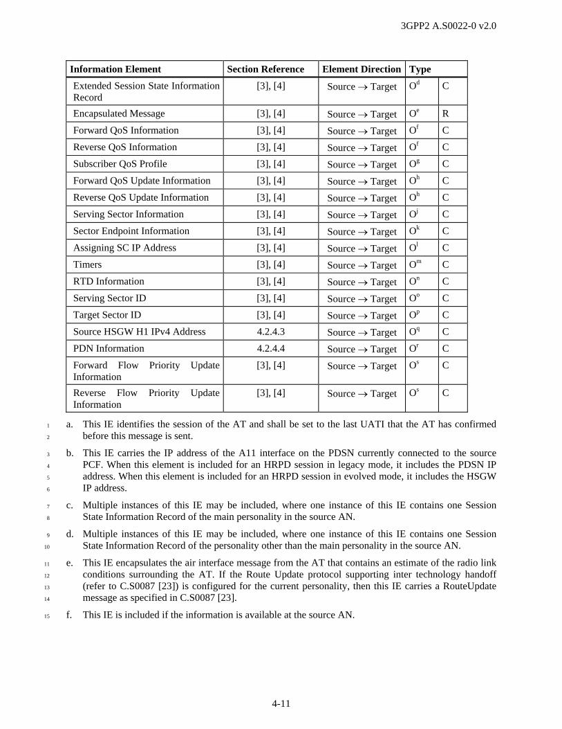
3GPP2 A.S0022-0 v2.0
4-11
Information Element Section Reference Element Direction Type
Extended Session State Information Record
[3], [4] Source Target Od C
Encapsulated Message [3], [4] Source Target Oe R
Forward QoS Information [3], [4] Source Target Of C
Reverse QoS Information [3], [4] Source Target Of C
Subscriber QoS Profile [3], [4] Source Target Og C
Forward QoS Update Information [3], [4] Source Target Oh C
Reverse QoS Update Information [3], [4] Source Target Oh C
Serving Sector Information [3], [4] Source Target Oj C
Sector Endpoint Information [3], [4] Source Target Ok C
Assigning SC IP Address [3], [4] Source Target Ol C
Timers [3], [4] Source Target Om C
RTD Information [3], [4] Source Target On C
Serving Sector ID [3], [4] Source Target Oo C
Target Sector ID [3], [4] Source Target Op C
Source HSGW H1 IPv4 Address 4.2.4.3 Source Target Oq C
PDN Information 4.2.4.4 Source Target Or C
Forward Flow Priority Update Information
[3], [4] Source Target Os C
Reverse Flow Priority Update Information
[3], [4] Source Target Os C
a. This IE identifies the session of the AT and shall be set to the last UATI that the AT has confirmed 1
before this message is sent. 2
b. This IE carries the IP address of the A11 interface on the PDSN currently connected to the source 3
PCF. When this element is included for an HRPD session in legacy mode, it includes the PDSN IP 4
address. When this element is included for an HRPD session in evolved mode, it includes the HSGW 5
IP address. 6
c. Multiple instances of this IE may be included, where one instance of this IE contains one Session 7
State Information Record of the main personality in the source AN. 8
d. Multiple instances of this IE may be included, where one instance of this IE contains one Session 9
State Information Record of the personality other than the main personality in the source AN. 10
e. This IE encapsulates the air interface message from the AT that contains an estimate of the radio link 11
conditions surrounding the AT. If the Route Update protocol supporting inter technology handoff 12
(refer to C.S0087 [23]) is configured for the current personality, then this IE carries a RouteUpdate 13
message as specified in C.S0087 [23]. 14
f. This IE is included if the information is available at the source AN. 15

3GPP2 A.S0022-0 v2.0
4-12
g. Subject to configuration5, this IE is included if the information is available at the source AN. If the 1
target AN subsequently receives this information from the PDSN, then the information received from 2
the PDSN takes precedence. 3
h. This IE is included to convey the PDSN updated QoS of one or more IP flows in the specified 4
direction. The target AN shall store the updated QoS lists received from the source AN and use them 5
when the specified personality is active when determining what QoS to grant for the associated IP 6
flows irrespective of the contents of the Subscriber QoS Profile. 7
i. If this IE is included in this message, its value shall be returned in the Correlation ID IE in the 8
corresponding A16-Session Transfer Response message. 9
j. This IE carries the sector information of the current serving sector to the target AN. Inclusion of this 10
IE implies that the source AN is requesting make-before-break session transfer. 11
k. Multiple instances of this IE may be included, where one instance of this IE contains one sector 12
information in the Active Set and the associated IP address and UDP port information. The target AN 13
may send an A17-Slave Attach Request message to the IP address and UDP port during Connected 14
State Session Transfer with cross-connectivity support to attach to the sector identified in the IE. 15
l. If the target AN can determine the unique assigning SC IP address from AT-ID, this IE may be 16
omitted. Otherwise, this IE shall be included. 17
m. If this IE is not included in this message, the target AN applies operator/manufacturer specific means 18
to perform LCM_UATI keep alive procedure. 19
n. This IE carries a round trip delay for the AT’s reference pilot. If this message is being sent to 20
accomplish an inter-technology handoff from E-UTRAN to eHRPD, this round trip delay value is an 21
estimate provided by the E-UTRAN system. If it is available, the source AN shall include this 22
information to assist the target AN in locating the center of search window of the sector(s) to which 23
the AT may switch. This IE is not sent for make-before-break session transfer. 24
o. This IE shall be included by an entity implemented to this revision of the specification. 25
p. This IE may be included. If the Encapsulated Message includes pilots on the target AN, then this IE 26
identifies the strongest reported pilot on the target AN to assist the target AN with mapping pilots. 27
q. This IE carries the IPv4 address of the H1 interface on the HSGW currently connected to the source 28
PCF when the AT is operating in evolved mode. 29
r. This IE shall be included when source AN receives this information over the S101 interface. It 30
includes the APN, P-GW Address, and GRE key for uplink traffic during E-UTRAN to eHRPD 31
optimized handoff. Multiple instances of this IE may be included in this message. This IE shall not be 32
included for intra-eHRPD mobility during active handoff. 33
s. This IE is included to convey the HSGW updated flow priority for one or more IP flows in the 34
specified direction. 35
t. If the identity is of type ESN or MEID, then this session transfer shall be for emergency services. 36
The following table shows the bitmap layout for the A16-Session Transfer Request message. 37
4.1.4.1 A16-Session Transfer Request
7 6 5 4 3 2 1 0 Octet
A16 Message Type = [01H] 1
5 This specification calls for this information to be sent from the PDSN (via the target PCF) to the target AN. However in certain configurations outside the scope of this specification, this information may be sent from the source AN in the A16-Session Transfer Request message instead. This information should not be sent over both A11 and A16.

3GPP2 A.S0022-0 v2.0
4-13
4.1.4.1 A16-Session Transfer Request
7 6 5 4 3 2 1 0 Octet
AT-ID: A16 Element Identifier = [0CH] 1
Length = [05H] 2
Reserved ATI Type = [0010 (UATI 32)] 3
(MSB) AT-ID = <any value> 4
5
6
(LSB) 7
Correlation ID: A16 Element Identifier = [18H] 1
Length = [04H] 2
(MSB) Correlation Value = <any value> 3
4
5
(LSB) 6
Mobile Identity (MN ID): A16 Element Identifier = [01H] 1
Length = [06H - 08H] (10 - 15 digits) 2
Identity Digit 1 = [0H-9H] (BCD) Odd/even Indicator = [1,0]
Type of Identity = [001 (MEID), 101 (ESN),
110] (IMSI)]
3
IF (Type of Identity = 110), Identity{1:
Identity Digit 3 = [0H-9H] (BCD) Identity Digit 2 = [0H-9H] (BCD) 4
… … …
Identity Digit N+1 = [0H-9H] (BCD) Identity Digit N = [0H-9H] (BCD) n
= [1111] (if even number of digits) Identity Digit N+2 = [0H-9H] (BCD) n+1
OR IF (Type of Identity = 101), Identity{1:
(MSB) ESN = <any value> 4
5
6
(LSB) 7
OR IF (Type of Identity = 001), Identity{1:
MEID Hex Digit 3 = [0H-FH] MEID Hex Digit 2 = [0H-FH] 4
MEID Hex Digit 5 = [0H-FH] MEID Hex Digit 4 = [0H-FH] 5
MEID Hex Digit 7 = [0H-FH] MEID Hex Digit 6 = [0H-FH] 6
MEID Hex Digit 9 = [0H-FH] MEID Hex Digit 8 = [0H-FH] 7
MEID Hex Digit 11 = [0H-FH] MEID Hex Digit 10 = [0H-FH] 8
MEID Hex Digit 13 = [0H-FH] MEID Hex Digit 12 = [0H-FH] 9
Fill = [FH] MEID Hex Digit 14 = [0H-FH] 10

3GPP2 A.S0022-0 v2.0
4-14
4.1.4.1 A16-Session Transfer Request
7 6 5 4 3 2 1 0 Octet
}Type of Identity
Access Network Identifiers: A16 Element Identifier = [02H] 1
Type = 01H 2
Length = [05H] 3
Reserved
(MSB) SID = <any value> 4
(LSB) 5
(MSB) NID = <any value> 6
(LSB) 7
PZID = <any value> 8
Source PDSN Address: A16 Element Identifier = [06H] 1
Length = [04H] 2
(MSB) PDSN IP Address 3
4
5
(LSB) 6
Session State Information Record {1+:
Session State Information Record: A16 Element Identifier = [03H] 1
(MSB) Length = [variable] 2
(LSB) 3
(MSB) Session State Information Record = <any value> 4
… …
(LSB) n
} Session State Information Record
Extended Session State Information Record {0, 1+:
Extended Session State Information Record: A16 Element Identifier = [05H] 1
(MSB) Length = [variable] 2
(LSB) 3
Reserved = [0000] Personality Index = [0H – FH] 4
(MSB) Session State Information Record = <any value> 5
… …
(LSB) n
} Extended Session State Information Record
Encapsulated Message {0, 1:
Encapsulated Message: A16 Element Identifier = [09H] 1

3GPP2 A.S0022-0 v2.0
4-15
4.1.4.1 A16-Session Transfer Request
7 6 5 4 3 2 1 0 Octet
Length = [variable] 2
(MSB) Protocol Type and Subtype = [000000H – FFFFFFH] 3
4
(LSB) 5
(MSB) Encapsulated Message = <any value> 6
… …
(LSB) n
} Encapsulated Message
Forward QoS Information: A16 Element Identifier = [12H] 1
Length = [variable] 2
Forward QoS Information Entry { 1-31:
Entry Length = [variable] j
SR_ID = [01H-1FH] j+1
Reserved = [000] Forward Flow Count = [1 - 31] j+2
Forward Flow Entry { Forward Flow ID Count :
Entry Length = [01H] k
Forward Flow ID = [00H – FFH] k+1
} Forward Flow Entry
} Forward QoS Information Entry
Reverse QoS Information: A16 Element Identifier = [13H] 1
Length = [variable] 2
Reverse QoS Information Entry { 1-31:
Entry Length = [variable] j
SR_ID = [01H-1FH] j+1
Reserved = [000] Reverse Flow Count = [1 - 31] j+2
Reverse Flow Entry { Reverse Flow Count :
Entry Length = [01H] k
Reverse Flow ID = [00H – FFH] k+1
} Reverse Flow Entry
} Reverse QoS Information Entry
Subscriber QoS Profile: A16 Element Identifier = [14H] 1
Length = [variable] 2
(MSB) Subscriber QoS Profile = <any value> 3
4
… …
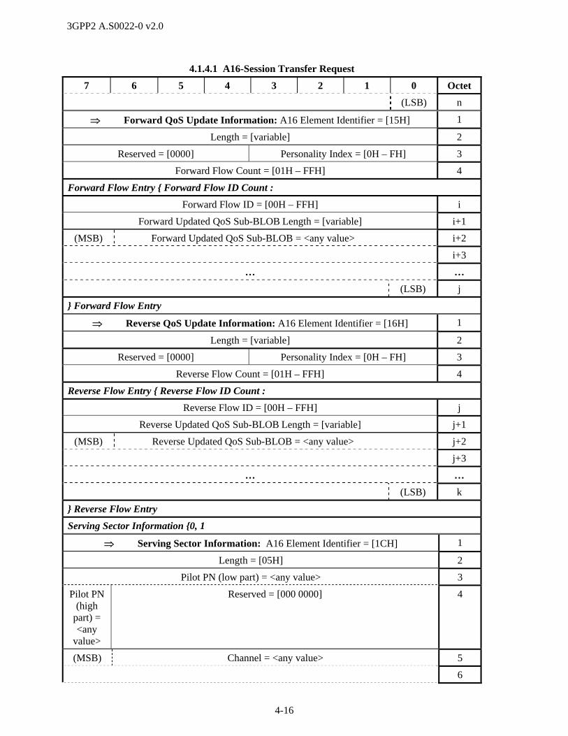
3GPP2 A.S0022-0 v2.0
4-16
4.1.4.1 A16-Session Transfer Request
7 6 5 4 3 2 1 0 Octet
(LSB) n
Forward QoS Update Information: A16 Element Identifier = [15H] 1
Length = [variable] 2
Reserved = [0000] Personality Index = [0H – FH] 3
Forward Flow Count = [01H – FFH] 4
Forward Flow Entry { Forward Flow ID Count :
Forward Flow ID = [00H – FFH] i
Forward Updated QoS Sub-BLOB Length = [variable] i+1
(MSB) Forward Updated QoS Sub-BLOB = <any value> i+2
i+3
… …
(LSB) j
} Forward Flow Entry
Reverse QoS Update Information: A16 Element Identifier = [16H] 1
Length = [variable] 2
Reserved = [0000] Personality Index = [0H – FH] 3
Reverse Flow Count = [01H – FFH] 4
Reverse Flow Entry { Reverse Flow ID Count :
Reverse Flow ID = [00H – FFH] j
Reverse Updated QoS Sub-BLOB Length = [variable] j+1
(MSB) Reverse Updated QoS Sub-BLOB = <any value> j+2
j+3
… …
(LSB) k
} Reverse Flow Entry
Serving Sector Information {0, 1
Serving Sector Information: A16 Element Identifier = [1CH] 1
Length = [05H] 2
Pilot PN (low part) = <any value> 3
Pilot PN (high
part) = <any
value>
Reserved = [000 0000] 4
(MSB) Channel = <any value> 5
6

3GPP2 A.S0022-0 v2.0
4-17
4.1.4.1 A16-Session Transfer Request
7 6 5 4 3 2 1 0 Octet
(LSB) 7
} Serving Sector Information
Sector Endpoint Information {1+:
Sector Endpoint Information: A16 Element Identifier = [1EH] 1
Length = [0BH] 2
Pilot PN (low part) = <any value> 3
Pilot PN (high
part) = <any
value>
Reserved = [000 0000] 4
(MSB) Channel 5
6
(LSB) 7
(MSB) UDP Port = [0000H – FFFFH] 8
(LSB) 9
(MSB) IPv4 Address = <any value> 10
11
12
(LSB) 13
} Sector Endpoint Information
Assigning SC IP Address: A16 Element Identifier = [20H] 1
Length = [04H] 2
(MSB) Assigning SC IP Address = <any value> 3
4
5
(LSB) 6
Timers: A16 Element Identifier = [21H] 1
Length = [07H] 2
Timer { 1:
Timer Type = [01H (Tsclose) ] n
Timer Length = [05H] n+1
(MSB) Starting Time = <any value> n+2
n+3
n+4
n+5
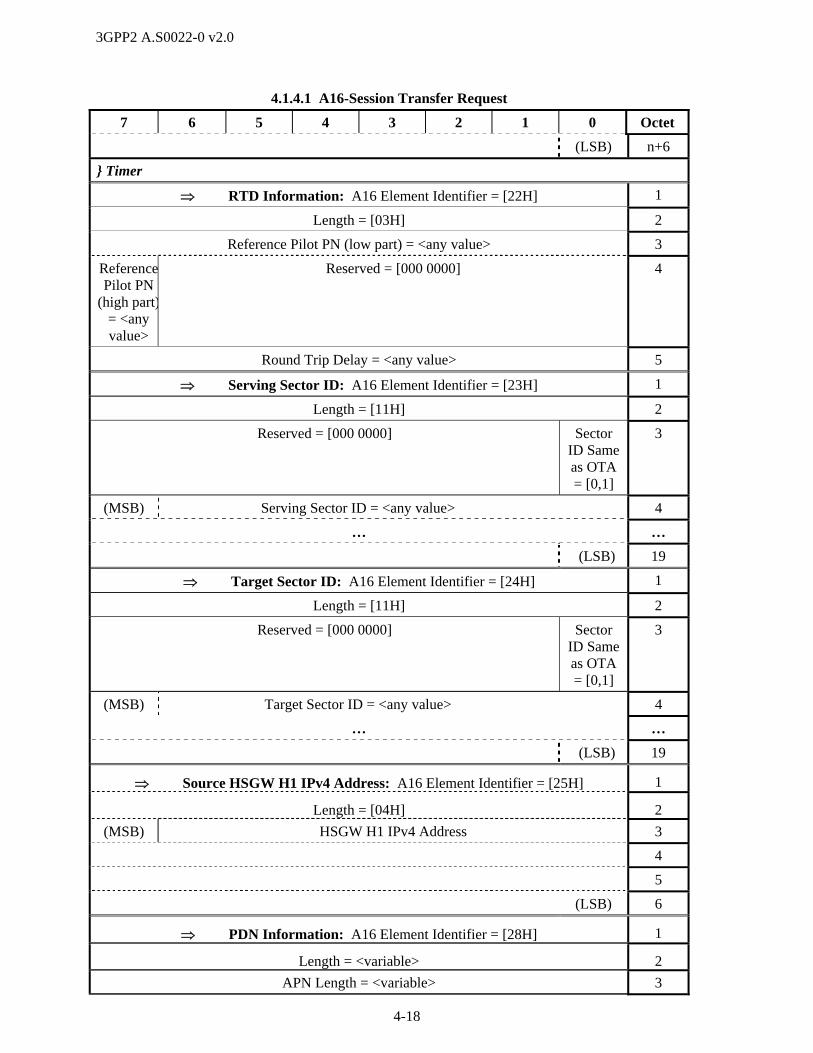
3GPP2 A.S0022-0 v2.0
4-18
4.1.4.1 A16-Session Transfer Request
7 6 5 4 3 2 1 0 Octet
(LSB) n+6
} Timer
RTD Information: A16 Element Identifier = [22H] 1
Length = [03H] 2
Reference Pilot PN (low part) = <any value> 3
ReferencePilot PN
(high part)= <any value>
Reserved = [000 0000] 4
Round Trip Delay = <any value> 5
Serving Sector ID: A16 Element Identifier = [23H] 1
Length = [11H] 2
Reserved = [000 0000] Sector ID Same as OTA = [0,1]
3
(MSB) Serving Sector ID = <any value> 4
… …
(LSB) 19
Target Sector ID: A16 Element Identifier = [24H] 1
Length = [11H] 2
Reserved = [000 0000] Sector ID Same as OTA = [0,1]
3
(MSB) Target Sector ID = <any value> 4
… …
(LSB) 19
Source HSGW H1 IPv4 Address: A16 Element Identifier = [25H] 1
Length = [04H] 2
(MSB) HSGW H1 IPv4 Address 3
4
5
(LSB) 6
PDN Information: A16 Element Identifier = [28H] 1
Length = <variable> 2
APN Length = <variable> 3

3GPP2 A.S0022-0 v2.0
4-19
4.1.4.1 A16-Session Transfer Request
7 6 5 4 3 2 1 0 Octet
(MSB) APN = <any value> 4
… …
(LSB) k
P-GW Address Type = [01H (IPv4), 02H (IPv6)] k+1
(MSB) P-GW Address= <any value> k+2
… …
(LSB) m
UL GRE Key Length = [04H] m+1
(MSB) UL GRE Key= <any value > m+2
… …
(LSB) n
Forward Flow Priority Update Information: A16 Element Identifier = [26H] 1
Length = [variable] 2
Reserved = [0000] Personality Index = [0H – FH] 3
Forward Flow Count = [01H – FFH] 4
Forward Flow Entry { Forward Flow ID Count :
Forward Flow ID = [00H – FFH] i
Reserved = [0000] Forward Updated Flow Priority = [0H – FH]
i+1
} Forward Flow Entry
Reverse Flow Priority Update Information: A16 Element Identifier = [27H] 1
Length = [variable] 2
Reserved = [0000] Personality Index = [0H – FH] 3
Reverse Flow Count = [01H – FFH] 4
Reverse Flow Entry { Reverse Flow ID Count :
Reverse Flow ID = [00H – FFH] i
Reserved = [0000] Reverse Updated Flow Priority = [0H – FH]
i+1
} Reverse Flow Entry
4.1.4.2 A16-Session Transfer Response 1
This message is sent from the target AN to the source AN in response to an A16-Session Transfer 2
Request message. 3
Information Element Section Reference Element Direction Type
A16 Message Type [3], [4] Target Source M
AT-ID [3], [4] Target Source Oa R

3GPP2 A.S0022-0 v2.0
4-20
Information Element Section Reference Element Direction Type
Correlation ID [3], [4] Target Source Og C
Session Transfer Information [3], [4] Target Source Ob R
Proposed Session State Information Record
[3], [4] Target Source Oc,d,f R
Extended Session State Information Record
[3], [4] Target Source Oe,f C
Forwarding Tunnel Parameter 4.2.4.5 Target Source Oh C
HRPDOpenLoopParameters 4.2.4.6 Target Source Oi C
a. This IE shall be set to the value of AT-ID in the A16-Session Transfer Request message. 1
b. If Signaling Link Protocol (SLP) Reset Required bit is set to ‘1’ then the source AN shall close the 2
connection when instructing the AT to switch to the target AN during HRPD Hard Handoff. 3
c. The source AN shall modify the main personality of the session according to the included Proposed 4
Session State Information Record before continuing with the session transfer. 5
d. The target AN shall include the necessary Proposed Session State Information Records for the source 6
AN to instruct the AT to connect to the new Active Set. 7
e. The source AN shall modify the non-main personality according to the included Extended Session 8
State Information Record before continuing with the session transfer. 9
f. The target AN shall not request the source AN to both modify the main personality and to set up a 10
new personality and instruct the AT to switch to that new personality. Multiple instances of this IE 11
may be included, where one instance of this IE contains one proposed Session State Information 12
Record for the indicated personality. 13
g. This IE shall be included if it was also included in the corresponding A16-Session Transfer Request 14
message and shall be set to the value received in that message. If it is not included in the A16-Session 15
Transfer Request message, this IE may be included in this message. 16
h. This IE shall be included when the A16-Session Transfer Request message contained one or more 17
PDN Information IEs and the T-HSGW included the S103 data forwarding related information in the 18
A11-Registration Reply message. This message may contain multiple instances of this IE. 19
i. This IE shall be included when the A16-Session Transfer Request message contained one or more 20
PDN Information IEs. Only one instance of this IE may occur in this message. 21
22
The following table shows the bitmap layout for the A16-Session Transfer Response message. 23
24
4.1.4.2 A16-Session Transfer Response
7 6 5 4 3 2 1 0 Octet
A16 Message Type = [02H] 1
AT-ID: A16 Element Identifier = [0CH] 1
Length = [05H] 2
Reserved = [0000] ATI Type = [0010 (UATI32)] 3
(MSB) AT-ID 4
5

3GPP2 A.S0022-0 v2.0
4-21
4.1.4.2 A16-Session Transfer Response
7 6 5 4 3 2 1 0 Octet
6
(LSB) 7
Correlation ID: A16 Element Identifier = [18H] 1
Length = [04H] 2
(MSB) Correlation Value = <any value> 3
4
5
(LSB) 6
Session Transfer Information: A16 Element Identifier = [0AH] 1
Length = [01H] 2
Reserved = [0000 000] SLP Reset Required = {0,1}
3
Proposed Session State Information Record {0, 1+:
Proposed Session State Information Record: A16 Element Identifier = [04H]
1
(MSB) Length = [variable] 2
(LSB) 3
(MSB) Session State Information Record 4
… …
(LSB) n
} Proposed Session State Information Record
Extended Session State Information Record {0, 1+:
Extended Session State Information Record: A16 Element Identifier = [05H]
1
(MSB) Length = [variable] 2
(LSB) 3
Reserved = [0000] Personality Index = <any value> 4
(MSB) Session State Information Record 5
… …
(LSB) n
} Extended Session State Information Record
Forwarding Tunnel Parameter: A16 Element Identifier = [29H] 1
Length = <variable> 2
APN Length = <variable> 3

3GPP2 A.S0022-0 v2.0
4-22
4.1.4.2 A16-Session Transfer Response
7 6 5 4 3 2 1 0 Octet
(MSB) APN = <any value > 4
…
(LSB) k
HSGW Address Type = [01H (IPv4), 02H (IPv6)] k+1
(MSB) HSGW Address= <any value > k+2
… …
(LSB) m
S103 GRE Key Length = <variable> m+1
(MSB) S103 GRE Key = <any value > m+2
… …
(LSB) n
HRPDOpenLoopParameters: A16 Element Identifier = [2AH] 1
Length = <variable> 2
(MSB) HRPDOpenLoopParameters = <any value > 3
… …
(LSB) n
4.1.5 A17 Message Definitions 1
Refer to A.S0008 [3] and A.S0009 [4]. 2
4.1.6 A18 Message Definitions 3
Refer to A.S0008 [3] and A.S0009 [4]. 4
4.1.7 A19 Message Definitions 5
Refer to A.S0008 [3] and A.S0009 [4]. 6
4.1.8 A21 Message Definitions 7
Refer to A.S0008 [3] and A.S0009 [4]. 8
4.2 Information Element Definitions 9
10
4.2.1 A13 Information Element Definitions 11
Refer to A.S0008 [3] and A.S0009 [4]. The content of these references shall apply except as superseded 12
by the following subsections. 13
4.2.1.1 A13 Information Element Identifiers 14
The following table lists all the IEs that make up the messages defined in section 4.1.1. The table includes 15
the Information Element Identifier (IEI) coding which distinguishes one IE from another. The table also 16
includes a section reference indicating where the IE coding can be found. 17
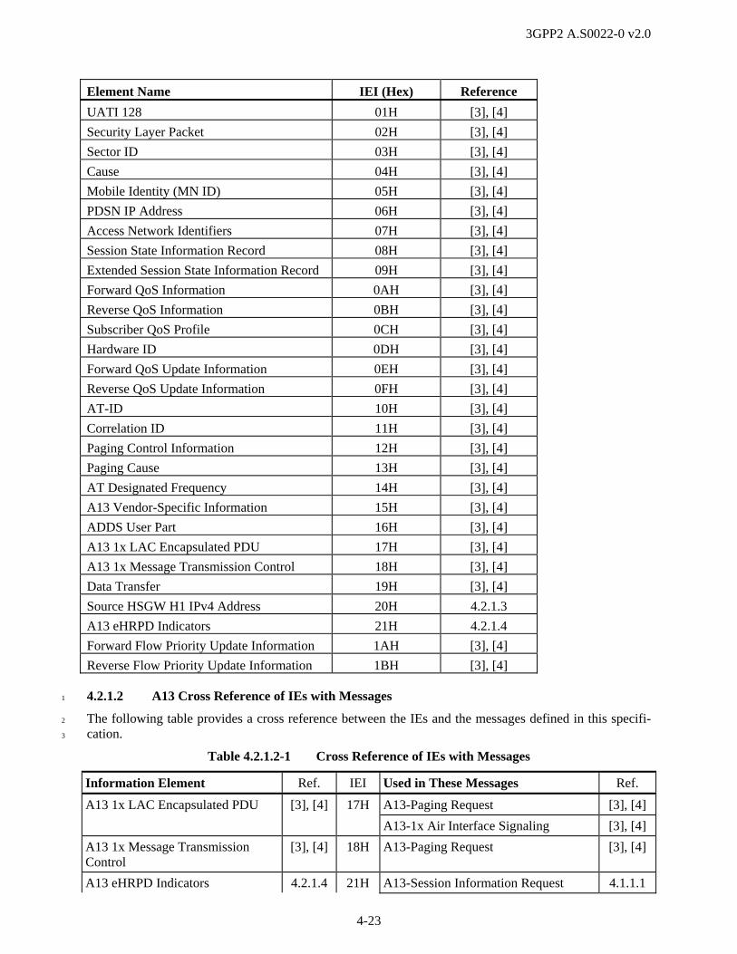
3GPP2 A.S0022-0 v2.0
4-23
Element Name IEI (Hex) Reference
UATI 128 01H [3], [4]
Security Layer Packet 02H [3], [4]
Sector ID 03H [3], [4]
Cause 04H [3], [4]
Mobile Identity (MN ID) 05H [3], [4]
PDSN IP Address 06H [3], [4]
Access Network Identifiers 07H [3], [4]
Session State Information Record 08H [3], [4]
Extended Session State Information Record 09H [3], [4]
Forward QoS Information 0AH [3], [4]
Reverse QoS Information 0BH [3], [4]
Subscriber QoS Profile 0CH [3], [4]
Hardware ID 0DH [3], [4]
Forward QoS Update Information 0EH [3], [4]
Reverse QoS Update Information 0FH [3], [4]
AT-ID 10H [3], [4]
Correlation ID 11H [3], [4]
Paging Control Information 12H [3], [4]
Paging Cause 13H [3], [4]
AT Designated Frequency 14H [3], [4]
A13 Vendor-Specific Information 15H [3], [4]
ADDS User Part 16H [3], [4]
A13 1x LAC Encapsulated PDU 17H [3], [4]
A13 1x Message Transmission Control 18H [3], [4]
Data Transfer 19H [3], [4]
Source HSGW H1 IPv4 Address 20H 4.2.1.3
A13 eHRPD Indicators 21H 4.2.1.4
Forward Flow Priority Update Information 1AH [3], [4]
Reverse Flow Priority Update Information 1BH [3], [4]
4.2.1.2 A13 Cross Reference of IEs with Messages 1
The following table provides a cross reference between the IEs and the messages defined in this specifi-2
cation. 3
Table 4.2.1.2-1 Cross Reference of IEs with Messages
Information Element Ref. IEI Used in These Messages Ref.
A13 1x LAC Encapsulated PDU [3], [4] 17H A13-Paging Request [3], [4]
A13-1x Air Interface Signaling [3], [4]
A13 1x Message Transmission Control
[3], [4] 18H A13-Paging Request [3], [4]
A13 eHRPD Indicators 4.2.1.4 21H A13-Session Information Request 4.1.1.1
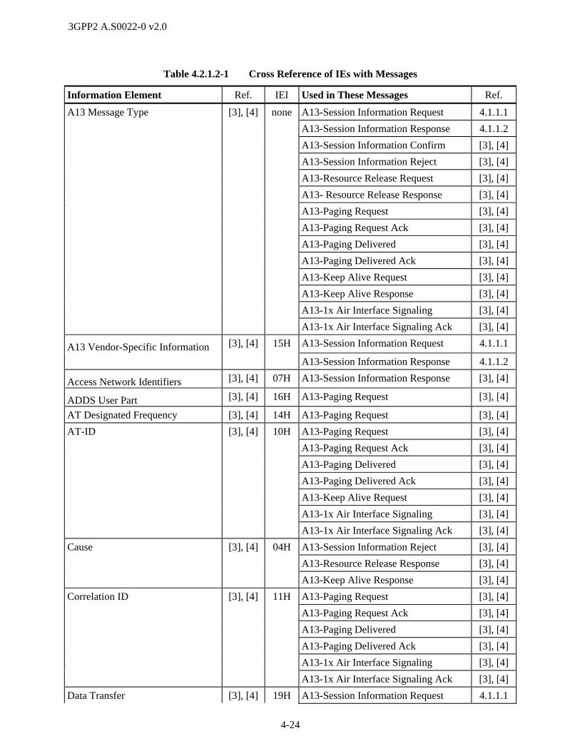
3GPP2 A.S0022-0 v2.0
4-24
Table 4.2.1.2-1 Cross Reference of IEs with Messages
Information Element Ref. IEI Used in These Messages Ref.
A13 Message Type [3], [4] none A13-Session Information Request 4.1.1.1
A13-Session Information Response 4.1.1.2
A13-Session Information Confirm [3], [4]
A13-Session Information Reject [3], [4]
A13-Resource Release Request [3], [4]
A13- Resource Release Response [3], [4]
A13-Paging Request [3], [4]
A13-Paging Request Ack [3], [4]
A13-Paging Delivered [3], [4]
A13-Paging Delivered Ack [3], [4]
A13-Keep Alive Request [3], [4]
A13-Keep Alive Response [3], [4]
A13-1x Air Interface Signaling [3], [4]
A13-1x Air Interface Signaling Ack [3], [4]
A13 Vendor-Specific Information [3], [4] 15H A13-Session Information Request 4.1.1.1
A13-Session Information Response 4.1.1.2
Access Network Identifiers [3], [4] 07H A13-Session Information Response [3], [4]
ADDS User Part [3], [4] 16H A13-Paging Request [3], [4]
AT Designated Frequency [3], [4] 14H A13-Paging Request [3], [4]
AT-ID [3], [4] 10H A13-Paging Request [3], [4]
A13-Paging Request Ack [3], [4]
A13-Paging Delivered [3], [4]
A13-Paging Delivered Ack [3], [4]
A13-Keep Alive Request [3], [4]
A13-1x Air Interface Signaling [3], [4]
A13-1x Air Interface Signaling Ack [3], [4]
Cause [3], [4] 04H A13-Session Information Reject [3], [4]
A13-Resource Release Response [3], [4]
A13-Keep Alive Response [3], [4]
Correlation ID [3], [4] 11H A13-Paging Request [3], [4]
A13-Paging Request Ack [3], [4]
A13-Paging Delivered [3], [4]
A13-Paging Delivered Ack [3], [4]
A13-1x Air Interface Signaling [3], [4]
A13-1x Air Interface Signaling Ack [3], [4]
Data Transfer [3], [4] 19H A13-Session Information Request 4.1.1.1
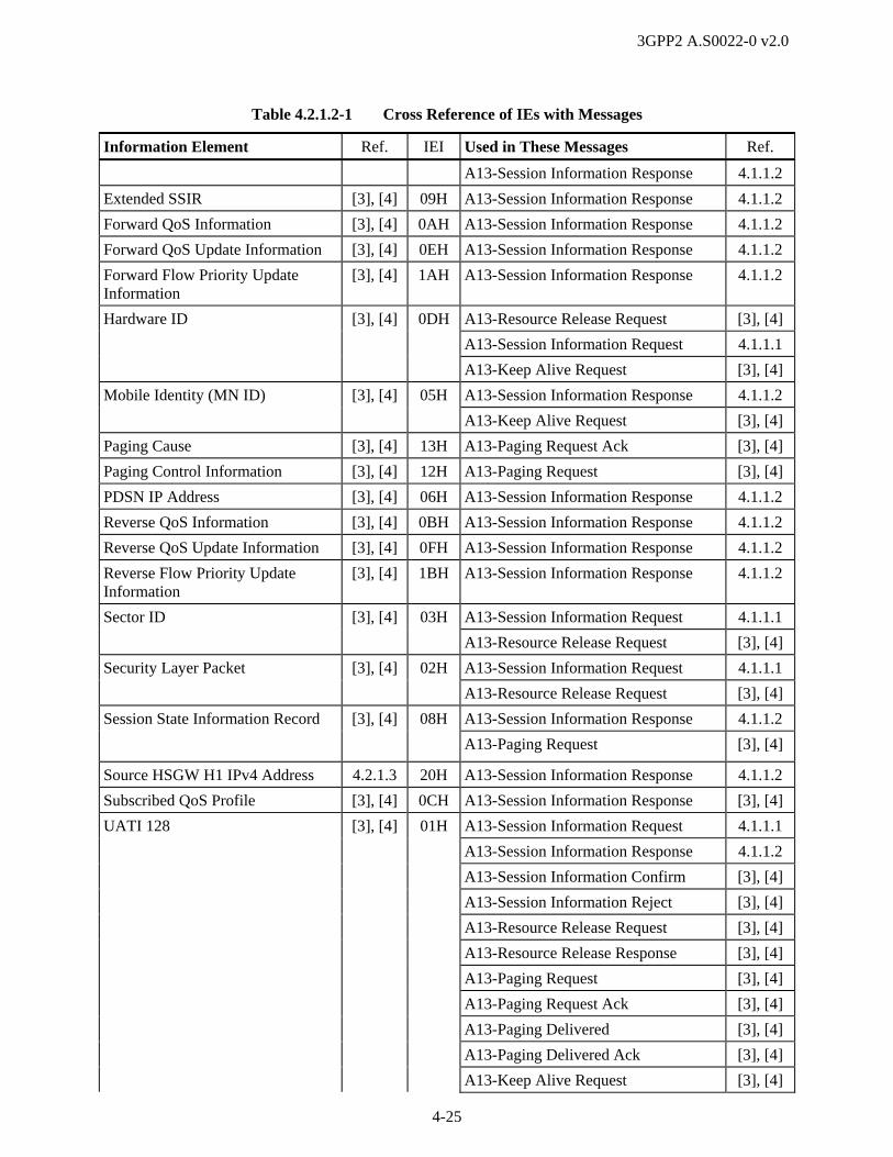
3GPP2 A.S0022-0 v2.0
4-25
Table 4.2.1.2-1 Cross Reference of IEs with Messages
Information Element Ref. IEI Used in These Messages Ref.
A13-Session Information Response 4.1.1.2
Extended SSIR [3], [4] 09H A13-Session Information Response 4.1.1.2
Forward QoS Information [3], [4] 0AH A13-Session Information Response 4.1.1.2
Forward QoS Update Information [3], [4] 0EH A13-Session Information Response 4.1.1.2
Forward Flow Priority Update Information
[3], [4] 1AH A13-Session Information Response 4.1.1.2
Hardware ID [3], [4] 0DH A13-Resource Release Request [3], [4]
A13-Session Information Request 4.1.1.1
A13-Keep Alive Request [3], [4]
Mobile Identity (MN ID) [3], [4] 05H A13-Session Information Response 4.1.1.2
A13-Keep Alive Request [3], [4]
Paging Cause [3], [4] 13H A13-Paging Request Ack [3], [4]
Paging Control Information [3], [4] 12H A13-Paging Request [3], [4]
PDSN IP Address [3], [4] 06H A13-Session Information Response 4.1.1.2
Reverse QoS Information [3], [4] 0BH A13-Session Information Response 4.1.1.2
Reverse QoS Update Information [3], [4] 0FH A13-Session Information Response 4.1.1.2
Reverse Flow Priority Update Information
[3], [4] 1BH A13-Session Information Response 4.1.1.2
Sector ID [3], [4] 03H A13-Session Information Request 4.1.1.1
A13-Resource Release Request [3], [4]
Security Layer Packet [3], [4] 02H A13-Session Information Request 4.1.1.1
A13-Resource Release Request [3], [4]
Session State Information Record [3], [4] 08H A13-Session Information Response 4.1.1.2
A13-Paging Request [3], [4]
Source HSGW H1 IPv4 Address 4.2.1.3 20H A13-Session Information Response 4.1.1.2
Subscribed QoS Profile [3], [4] 0CH A13-Session Information Response [3], [4]
UATI 128 [3], [4] 01H A13-Session Information Request 4.1.1.1
A13-Session Information Response 4.1.1.2
A13-Session Information Confirm [3], [4]
A13-Session Information Reject [3], [4]
A13-Resource Release Request [3], [4]
A13-Resource Release Response [3], [4]
A13-Paging Request [3], [4]
A13-Paging Request Ack [3], [4]
A13-Paging Delivered [3], [4]
A13-Paging Delivered Ack [3], [4]
A13-Keep Alive Request [3], [4]

3GPP2 A.S0022-0 v2.0
4-26
Table 4.2.1.2-1 Cross Reference of IEs with Messages
Information Element Ref. IEI Used in These Messages Ref.
A13-Keep Alive Response [3], [4]
A13-1x Air Interface Signaling [3], [4]
A13-1x Air Interface Signaling Ack [3], [4]
4.2.1.3 Source HSGW H1 IPv4 Address 1
This IE is used to provide the source HSGW H1 IPv4 address to the target evolved AN/PCF. This address 2
is passed to the target HSGW if the target eAN/ePCF cannot connect to the source HSGW. 3
4.2.1.3 Source HSGW H1 IPv4 Address
7 6 5 4 3 2 1 0 Octet
A13 Element Identifier = [20H] 1
Length 2
(MSB) HSGW H1 IPv4 Address 3
4
5
(LSB) 6
Length This field contains the number of octets in this IE following this field as 4
a binary number. 5
HSGW H1 IPv4 Address This field is set to the IPv4 address of the H1 interface (refer to X.S0057 6
[25]) of the source HSGW. 7
4.2.1.4 A13 eHRPD Indicators 8
This IE indicates that the sending AN/PCF is an eAN/ePCF. 9
4.2.1.4 A13 eHRPD Indicators
7 6 5 4 3 2 1 0 Octet
A13 Element Identifier = [21H] 1
Length 2
Reserved Evolved AN/PCF
3
Length This field contains the number of octets in this IE following this field as 10
a binary number. 11
Evolved AN/PCF This field shall be set to ‘1’ to indicate that the target is an evolved 12
AN/PCF. Otherwise this field shall be set to ‘0’. 13
14
4.2.2 A14 Information Element Definitions 15
Refer to A.S0009 [4]. The content of these references shall apply except as superseded by the following 16
subsections. 17
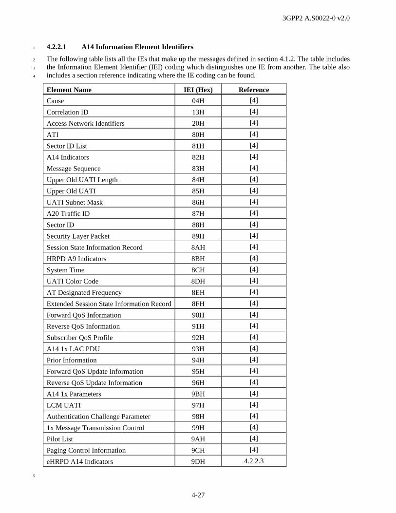
3GPP2 A.S0022-0 v2.0
4-27
4.2.2.1 A14 Information Element Identifiers 1
The following table lists all the IEs that make up the messages defined in section 4.1.2. The table includes 2
the Information Element Identifier (IEI) coding which distinguishes one IE from another. The table also 3
includes a section reference indicating where the IE coding can be found. 4
Element Name IEI (Hex) Reference
Cause 04H [4]
Correlation ID 13H [4]
Access Network Identifiers 20H [4]
ATI 80H [4]
Sector ID List 81H [4]
A14 Indicators 82H [4]
Message Sequence 83H [4]
Upper Old UATI Length 84H [4]
Upper Old UATI 85H [4]
UATI Subnet Mask 86H [4]
A20 Traffic ID 87H [4]
Sector ID 88H [4]
Security Layer Packet 89H [4]
Session State Information Record 8AH [4]
HRPD A9 Indicators 8BH [4]
System Time 8CH [4]
UATI Color Code 8DH [4]
AT Designated Frequency 8EH [4]
Extended Session State Information Record 8FH [4]
Forward QoS Information 90H [4]
Reverse QoS Information 91H [4]
Subscriber QoS Profile 92H [4]
A14 1x LAC PDU 93H [4]
Prior Information 94H [4]
Forward QoS Update Information 95H [4]
Reverse QoS Update Information 96H [4]
A14 1x Parameters 9BH [4]
LCM UATI 97H [4]
Authentication Challenge Parameter 98H [4]
1x Message Transmission Control 99H [4]
Pilot List 9AH [4]
Paging Control Information 9CH [4]
eHRPD A14 Indicators 9DH 4.2.2.3
5

3GPP2 A.S0022-0 v2.0
4-28
4.2.2.2 A14 Cross Reference of IEs with Messages 1
The following table provides a cross reference between the IEs and the messages defined in this 2
specification. 3
Table 4.2.2.2-1 Cross Reference of IEs with Messages
Information Element Ref. IEI Used in These Messages Ref.
A14 1x LAC Encapsulated PDU [4] 93H A14-1x Service Page [4]
A14-1x Service Transfer [4]
1x Message Transmission Control [4] 99H A14-1x Service Page [4]
A14-1x Service Transfer [4]
A14 Indicators [4] 82H A14-General Update [4]
A14-Authentication Completed [4]
A14-Paging Request [4]
A14-1x Service Page [4]
A14 1x Parameters [4] 9BH A14-1x Parameters [4]
A14 Message Type [4] none A14-UATI Request 4.1.2.1
A14-UATI Assignment [4]
A14-UATI Complete [4]
A14-UATI Complete Ack [4]
A14-UATI Assignment Failure [4]
A14-General Update [4]
A14-General Update Complete [4]
A14-Authentication Command [4]
A14-Authentication Request [4]
A14-Authentication Response [4]
A14-Authentication Completed [4]
A4-Authentication Completed Ack [4]
A14-Authentication Failure [4]
A14-Authentication Failure Ack [4]
A14-Session Release Command [4]
A14-Session Release [4]
A14-Session Release Complete [4]
A14-Session Information Update [4]
A14-Session Information Update Ack [4]
A14-Paging Request [4]
A14-Paging Request Ack [4]
A14-Paging Response [4]
A14-Paging Response Ack [4]
A14-Keep Alive Request [4]
A4-Keep Alive Request Ack [4]

3GPP2 A.S0022-0 v2.0
4-29
Table 4.2.2.2-1 Cross Reference of IEs with Messages
Information Element Ref. IEI Used in These Messages Ref.
A14-1x Service Page [4]
A14-1x Service Page Ack [4]
A14-1x Service Page Delivered [4]
A14-1x Service Transfer [4]
A14-1x Service Transfer Delivered [4]
A14-1x Parameters [4]
A14-1x Parameters Ack [4]
A14-1x Parameters Request [4]
A14-Radio Update Request [4]
A14-Radio Update Response [4]
A21 1x Parameters [4] 02H A14 1x Parameters [4]
A21 Downlink Radio Environment [4] 03H A14 1x Service Transfer [4]
Access Network Identifiers [4] 20H A14-General Update [4]
AT Designated Frequency [4] 8EH A14-1x Service Page [4]
A14-General Update [4]
A14-Paging Request [4]
A14-Session Release Command [4]
ATI [4] 80H A14-UATI Request 4.1.2.1
A14-UATI Assignment [4]
A14-UATI Complete [4]
A14-UATI Complete Ack [4]
A14-UATI Assignment Failure [4]
A14-General Update [4]
A14-General Update Complete [4]
A14-Authentication Command [4]
A14-Authentication Request [4]
A14-Authentication Response [4]
A14-Authentication Completed [4]
A4-Authentication Completed Ack [4]
A14-Authentication Failure [4]
A14-Authentication Failure Ack [4]
A14-Session Release Command [4]
A14-Session Release [4]
A14-Session Release Complete [4]
A14-Session Information Update [4]
A14-Session Information Update Ack [4]

3GPP2 A.S0022-0 v2.0
4-30
Table 4.2.2.2-1 Cross Reference of IEs with Messages
Information Element Ref. IEI Used in These Messages Ref.
A14-Paging Request [4]
A14-Paging Request Ack [4]
A14-Paging Response [4]
A14-Paging Response Ack [4]
A14-Keep Alive Request [4]
A4-Keep Alive Request Ack [4]
A14-1x Service Page [4]
A14-1x Service Page Ack [4]
A14-1x Service Page Delivered [4]
A14-1x Service Transfer [4]
A14-1x Service Transfer Delivered [4]
A14-1x Ack [4]
A14-Radio Update Request [4]
A14-Radio Update Response [4]
A20 Traffic ID [4] 87H A14-Authentication Request [4]
A14-Authentication Response [4]
Authentication Challenge Parameter (RAND)
[4] 98H A14-1x Service Transfer [4]
A14-1x Parameters [4]
Cause [4] 04H A14-UATI Assignment Failure [4]
A14-General Update Complete [4]
A14-Authentication Completed [4]
A14-Authentication Failure [4]
A14-Session Release Command [4]
A14-Session Release [4]
A14-Session Release Complete [4]
A14-Paging Response [4]
Correlation ID [4] 13H A14-UATI Request 4.1.2.1
A14-UATI Assignment [4]
A14-UATI Complete [4]
A14-UATI Complete Ack [4]
A14-UATI Assignment Failure [4]
A14-General Update [4]
A14-General Update Complete [4]
A14-Authentication Command [4]
A14-Authentication Request [4]
A14-Authentication Response [4]

3GPP2 A.S0022-0 v2.0
4-31
Table 4.2.2.2-1 Cross Reference of IEs with Messages
Information Element Ref. IEI Used in These Messages Ref.
A14-Authentication Completed [4]
A4-Authentication Completed Ack [4]
A14-Authentication Failure [4]
A14-Authentication Failure Ack [4]
A14-Session Release Command [4]
A14-Session Release [4]
A14-Session Release Complete [4]
A14-Session Information Update [4]
A14-Session Information Update Ack [4]
A14-Paging Request [4]
A14-Paging Request Ack [4]
A14-Paging Response [4]
A14-Paging Response Ack [4]
A14-Keep Alive Request [4]
A14-Keep Alive Request Ack [4]
A14-1x Service Page [4]
A14-1x Service Page Ack [4]
A14-1x Service Page Delivered [4]
A14-1x Service Transfer [4]
A14-1x Service Transfer Delivered [4]
A14-1x Parameters [4]
A14-1x Parameters Ack [4]
A14-1x Parameters Request [4]
A14-Radio Update Request [4]
A14-Radio Update Response [4]
eHRPD A14 Indicators 4.2.2.3 9DH A14-UATI Request 4.1.2.1
Extended SSIR [4] 8FH A14-General Update Complete [4]
A14-Session Release Command [4]
A14-Session Information Update [4]
A14-Paging Request [4]
A14-Paging Response Ack [4]
A14-Keep Alive Request [4]
A14-1x Service Page [4]
Forward QoS Information [4] 90H A14-Paging Request [4]
Forward QoS Update Information [4] 95H A14-Paging Request [4]
LCM UATI [4] 97H A14-Session Information Update [4]

3GPP2 A.S0022-0 v2.0
4-32
Table 4.2.2.2-1 Cross Reference of IEs with Messages
Information Element Ref. IEI Used in These Messages Ref.
Message Sequence [4] 83H A14-UATI Assignment [4]
A14-UATI Complete [4]
Mobile Identity (MN ID) [4] 05H A13-Session Information Response [4]
A21-1x Air Interface Signaling [4]
A21-1x Air Ack [4]
Paging Control Information [4] 9CH A14-Paging Request [4]
A14-1x Service Page [4]
Pilot List [4] 9AH A14-1x Service Transfer [4]
A14-Radio Update Request [4]
A14-Radio Update Response [4]
Prior Information [4] 94H A14-Session Information Update [4]
Reverse QoS Information [4] 91H A14-Paging Request [4]
Reverse QoS Update Information [4] 96H A14-Paging Request [4]
Sector ID [4] 88H A14-UATI Request 4.1.2.1
A14-UATI Assignment [4]
A14-UATI Complete [4]
A14-General Update [4]
A14-Session Release Command [4]
A14-Session Release [4]
A14-Paging Request [4]
A14-Paging Response [4]
A14-Keep Alive Request [4]
A14-1x Service Page [4]
Sector ID List [4] 81H A14-Session Release Command [4]
A14-Paging Request [4]
A14-1x Service Page [4]
A14-Keep Alive Request [4]
Security Layer Packet [4] 89H A14-UATI Request 4.1.2.1
A14-UATI Complete [4]
A14-General Update [4]
A14-Session Release [4]
Session State Information Record [4] 8AH A14-General Update [4]
A14-General Update Complete [4]
A14-Session Release Command [4]
A14-Session Information Update [4]
A14-Paging Request [4]

3GPP2 A.S0022-0 v2.0
4-33
Table 4.2.2.2-1 Cross Reference of IEs with Messages
Information Element Ref. IEI Used in These Messages Ref.
A14-Paging Response Ack [4]
A14-Keep Alive Request [4]
A14-1x Service Page [4]
Subscriber QoS Profile [4] 92H A14-Paging Request [4]
System Time [4] 8CH A14-UATI Request 4.1.2.1
A14-UATI Complete [4]
A14-General Update [4]
A14-Session Release [4]
UATI Color Code [4] 8DH A14-UATI Assignment [4]
UATI Subnet Mask [4] 86H A14-UATI Assignment [4]
Upper Old UATI [4] 85H A14-UATI Complete [4]
Upper Old UATI Length [4] 84H A14-UATI Assignment [4]
A14-UATI Complete [4]
1
4.2.2.3 eHRPD A14 Indicators 2
This IE is used to provide indications related to eHRPD operations. 3
4.2.2.3 eHRPD A14 Indicators
7 6 5 4 3 2 1 0 Octet
eHRPD A14 Indicators: A14 Element Identifier = [9DH] 1
Length 2
Reserved Tunnel Mode
3
Length This field contains the number of octets in this IE following this field as 4
a binary number. 5
Tunnel Mode The field indicates whether or not the eAT is operating on the eHRPD 6
radio, as follows: 7
• The Tunnel Mode indication is set to 0 to indicate that the eAT is 8
operating on the eHRPD radio (e.g., the eAT is communicating 9
directly via eHRPD). 10
• The Tunnel Mode indication is set to 1 to indicate that the eAT is not 11
operating on the eHRPD radio (e.g., the eAT is communicating via a 12
tunnel from another access technology). 13
When the eHRPD system supports optimized mobility between eHRPD 14
and E-UTRAN, the eAN includes the Tunnel Mode indication in the 15
A14-UATI Request messages sent to the ePCF for an evolved mode 16
session, and sets the value of the Tunnel Mode indication value 17
appropriately. The eAN may not include the Tunnel Mode indication in 18
any A14-UATI Request messages sent to the ePCF for an evolved mode 19

3GPP2 A.S0022-0 v2.0
4-34
session if the eHRPD system does not support optimized mobility 1
between eHRPD and E-UTRAN. 2
The ePCF shall treat the absence of the Tunnel Mode indication from an 3
A14-UATI Request message for an evolved mode session the same as 4
Tunnel Mode indication of ‘0’. 5
6
4.2.3 A15 Information Element Definitions 7
Refer to A.S0009 [4]. 8
4.2.4 A16 Information Element Definitions 9
Refer to A.S0008 [3] and A.S0009 [4]. The content of these references shall apply except as superceded 10
by the following subsections. 11
4.2.4.1 A16 Information Element Identifiers 12
The following table lists all the IEs that make up the messages defined in section 4.1.4. The table includes 13
the Information Element Identifier (IEI) coding which distinguishes one IE from another. The table also 14
includes a section reference indicating where the IE coding can be found. 15
Element Name Identifier (Hex) Reference
Mobile Identity (MN ID) 01H [3], [4]
Access Network Identifiers 02H [3], [4]
Session State Information Record 03H [3], [4]
Proposed Session State Information Record
04H [3], [4]
Extended Session State Information Record
05H [3], [4]
Source PDSN Address 06H [3], [4]
Reserved 07H – 08H N/A
Encapsulated Message 09H [3], [4]
Session Transfer Information 0AH [3], [4]
Session Transfer Abort Cause 0BH [3], [4]
AT-ID 0CH [3], [4]
ConfirmedUATI 0DH [3], [4]
AssignedUATI 0EH [3], [4]
LCM_UATI 0FH [3], [4]
SLP-D Parameters 10H [3], [4]
SLP-F Parameters 11H [3], [4]
Forward QoS Information 12H [3], [4]
Reverse QoS Information 13H [3], [4]
Subscriber QoS Profile 14H [3], [4]
Forward QoS Update Information 15H [3], [4]
Reverse QoS Update Information 16H [3], [4]
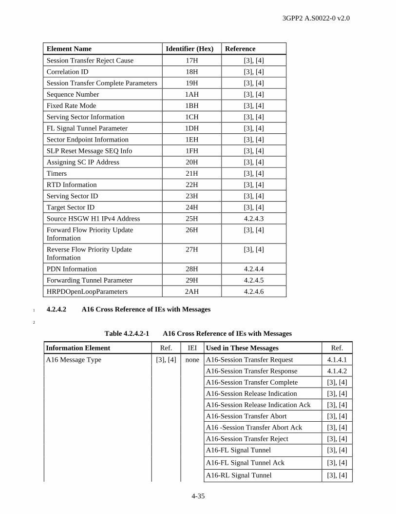
3GPP2 A.S0022-0 v2.0
4-35
Element Name Identifier (Hex) Reference
Session Transfer Reject Cause 17H [3], [4]
Correlation ID 18H [3], [4]
Session Transfer Complete Parameters 19H [3], [4]
Sequence Number 1AH [3], [4]
Fixed Rate Mode 1BH [3], [4]
Serving Sector Information 1CH [3], [4]
FL Signal Tunnel Parameter 1DH [3], [4]
Sector Endpoint Information 1EH [3], [4]
SLP Reset Message SEQ Info 1FH [3], [4]
Assigning SC IP Address 20H [3], [4]
Timers 21H [3], [4]
RTD Information 22H [3], [4]
Serving Sector ID 23H [3], [4]
Target Sector ID 24H [3], [4]
Source HSGW H1 IPv4 Address 25H 4.2.4.3
Forward Flow Priority Update Information
26H [3], [4]
Reverse Flow Priority Update Information
27H [3], [4]
PDN Information 28H 4.2.4.4
Forwarding Tunnel Parameter 29H 4.2.4.5
HRPDOpenLoopParameters 2AH 4.2.4.6
4.2.4.2 A16 Cross Reference of IEs with Messages 1
2
Table 4.2.4.2-1 A16 Cross Reference of IEs with Messages
Information Element Ref. IEI Used in These Messages Ref.
A16 Message Type [3], [4] none A16-Session Transfer Request 4.1.4.1
A16-Session Transfer Response 4.1.4.2
A16-Session Transfer Complete [3], [4]
A16-Session Release Indication [3], [4]
A16-Session Release Indication Ack [3], [4]
A16-Session Transfer Abort [3], [4]
A16 -Session Transfer Abort Ack [3], [4]
A16-Session Transfer Reject [3], [4]
A16-FL Signal Tunnel [3], [4]
A16-FL Signal Tunnel Ack [3], [4]
A16-RL Signal Tunnel [3], [4]

3GPP2 A.S0022-0 v2.0
4-36
Table 4.2.4.2-1 A16 Cross Reference of IEs with Messages
Information Element Ref. IEI Used in These Messages Ref.
A16-RL Signal Tunnel Ack [3], [4]
A16-Attributes Update [3], [4]
A16-Attributes Update Ack [3], [4]
Access Network Identifiers [3], [4] 02H A16-Session Transfer Request 4.1.4.1
AssignedUATI [3], [4] 0EH A16-Session Transfer Complete [3], [4]
Assigning SC IP Address [3], [4] 20H A16-Session Transfer Request 4.1.4.1
AT-ID [3], [4] 0CH A16-Session Transfer Request 4.1.4.1
A16-Session Transfer Response 4.1.4.2
A16-Session Transfer Complete [3], [4]
A16-Session Release Indication [3], [4]
A16-Session Release Indication Ack [3], [4]
A16-Session Transfer Abort [3], [4]
A16 -Session Transfer Abort Ack [3], [4]
A16-Session Transfer Reject [3], [4]
A16-FL Signal Tunnel [3], [4]
A16-FL Signal Tunnel Ack [3], [4]
A16-RL Signal Tunnel [3], [4]
A16-RL Signal Tunnel Ack [3], [4]
A16-Attributes Update [3], [4]
A16-Attributes Update Ack [3], [4]
ConfirmedUATI [3], [4] 0DH A16-Session Transfer Complete [3], [4]
Correlation ID [3], [4] 18H A16-Session Transfer Request 4.1.4.1
A16-Session Transfer Response 4.1.4.2
A16-Session Transfer Complete [3], [4]
A16-Session Release Indication [3], [4]
A16-Session Release Indication Ack [3], [4]
A16-Session Transfer Abort [3], [4]
A16 -Session Transfer Abort Ack [3], [4]
A16-Session Transfer Reject [3], [4]
Encapsulated Message [3], [4] 09H A16-Session Transfer Request 4.1.4.1
A16-FL Signal Tunnel [3], [4]
A16-RL Signal Tunnel [3], [4]
Extended Session State Information Record
[3], [4] 05H A16-Session Transfer Request 4.1.4.1
A16-Session Transfer Response 4.1.4.2
A16-Session Transfer Complete [3], [4]

3GPP2 A.S0022-0 v2.0
4-37
Table 4.2.4.2-1 A16 Cross Reference of IEs with Messages
Information Element Ref. IEI Used in These Messages Ref.
A16-Attributes Update [3], [4]
Fixed Rate Mode [3], [4] 1BH A16-Session Transfer Complete [3], [4]
FL Signal Tunnel Parameter [3], [4] 1DH A16-FL Signal Tunnel [3], [4]
Forward Flow Priority Update Information
[3], [4] 26H A16-Session Transfer Request 4.1.4.1
Forward QoS Information [3], [4] 12H A16-Session Transfer Request 4.1.4.1
Forward QoS Update Information [3], [4] 15H A16-Session Transfer Request 4.1.4.1
Forwarding Tunnel Parameter 4.2.4.5 29H A16-Session Transfer Response 4.1.4.2
HRPDOpenLoopParameters 4.2.4.6 2AH A16-Session Transfer Response 4.1.4.2
LCM UATI [3], [4] 0FH A16-Session Transfer Complete [3], [4]
Mobile Identity (MN ID) [3], [4] 01H A16-Session Transfer Request 4.1.4.1
PDN Information 4.2.4.4 28H A16-Session Transfer Request 4.1.4.1
Proposed Session State Information Record
[3], [4] 04H A16-Session Transfer Response 4.1.4.2
A16-Attributes Update [3], [4]
Reverse Flow Priority Update Information
[3], [4] 27H A16-Session Transfer Request 4.1.4.1
Reverse QoS Information [3], [4] 13H A16-Session Transfer Request 4.1.4.1
Reverse QoS Update Information [3], [4] 16H A16-Session Transfer Request 4.1.4.1
RTD Information [3], [4] 22H A16-Session Transfer Request 4.1.4.1
Sector Endpoint Information [3], [4] 1EH A16-Session Transfer Request 4.1.4.1
A16-Attributes Update [3], [4]
Sequence Number [3], [4] 1AH A16-FL Signal Tunnel [3], [4]
A16-FL Signal Tunnel Ack [3], [4]
A16-RL Signal Tunnel [3], [4]
A16-RL Signal Tunnel Ack [3], [4]
A16-Attributes Update [3], [4]
A16-Attributes Update Ack [3], [4]
Serving Sector ID [3], [4] 23H A16-Session Transfer Request 4.1.4.1
Serving Sector Information [3], [4] 1CH A16-Session Transfer Request 4.1.4.1
A16-Session Transfer Complete [3], [4]
A16-Attributes Update [3], [4]
Session Transfer Abort Cause [3], [4] 0BH A16-Session Transfer Abort [3], [4]
Session Transfer Complete Parameters
[3], [4] 19H A16-Session Transfer Complete [3], [4]
Session Transfer Reject Cause [3], [4] 17H A16-Session Transfer Reject [3], [4]
Session Transfer Information [3], [4] 0AH A16-Session Transfer Response 4.1.4.2
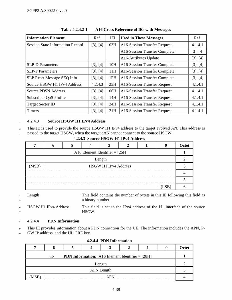
3GPP2 A.S0022-0 v2.0
4-38
Table 4.2.4.2-1 A16 Cross Reference of IEs with Messages
Information Element Ref. IEI Used in These Messages Ref.
Session State Information Record [3], [4] 03H A16-Session Transfer Request 4.1.4.1
A16-Session Transfer Complete [3], [4]
A16-Attributes Update [3], [4]
SLP-D Parameters [3], [4] 10H A16-Session Transfer Complete [3], [4]
SLP-F Parameters [3], [4] 11H A16-Session Transfer Complete [3], [4]
SLP Reset Message SEQ Info [3], [4] 1FH A16-Session Transfer Complete [3], [4]
Source HSGW H1 IPv4 Address 4.2.4.3 25H A16-Session Transfer Request 4.1.4.1
Source PDSN Address [3], [4] 06H A16-Session Transfer Request 4.1.4.1
Subscriber QoS Profile [3], [4] 14H A16-Session Transfer Request 4.1.4.1
Target Sector ID [3], [4] 24H A16-Session Transfer Request 4.1.4.1
Timers [3], [4] 21H A16-Session Transfer Request 4.1.4.1
4.2.4.3 Source HSGW H1 IPv4 Address 1
This IE is used to provide the source HSGW H1 IPv4 address to the target evolved AN. This address is 2
passed to the target HSGW, when the target eAN cannot connect to the source HSGW. 3
4.2.4.3 Source HSGW H1 IPv4 Address
7 6 5 4 3 2 1 0 Octet
A16 Element Identifier = [25H] 1
Length 2
(MSB) HSGW H1 IPv4 Address 3
4
5
(LSB) 6
Length This field contains the number of octets in this IE following this field as 4
a binary number. 5
HSGW H1 IPv4 Address This field is set to the IPv4 address of the H1 interface of the source 6
HSGW. 7
4.2.4.4 PDN Information 8
This IE provides information about a PDN connection for the UE. The information includes the APN, P-9
GW IP address, and the UL GRE key. 10
4.2.4.4 PDN Information
7 6 5 4 3 2 1 0 Octet
PDN Information: A16 Element Identifier = [28H] 1
Length 2
APN Length 3
(MSB) APN 4

3GPP2 A.S0022-0 v2.0
4-39
4.2.4.4 PDN Information
7 6 5 4 3 2 1 0 Octet
… …
(LSB) k
P-GW Address Type k+1
(MSB) P-GW Address k+2
… …
(LSB) m
UL GRE Key Length m+1
(MSB) UL GRE Key m+2
… …
(LSB) n
Length This field contains the number of octets in this IE following this field as 1
a binary number. 2
APN Length This field contains the number of following octets that contain the APN. 3
APN This field contains the Access Point Name for the PDN. 4
P-GW Address Type This field is encoded as 01H to indicate that the following four octets 5
contain an IPv4 address for the P-GW, or as 02H to indicate that the 6
following 16 octets contain an IPv6 address for the P-GW. 7
P-GW Address This field contains either an IPv4 or an IPv6 address for the P-GW 8
depending on the value of the P-GW Address Type field. 9
UL GRE Key Length This field contains the number of following octets that contain the UL 10
GRE key for this PDN connection. 11
UL GRE Key This field contains the UL GRE key for this PDN connection. 12
13
4.2.4.5 Forwarding Tunnel Parameter 14
This IE provides the APN, IP address, and GRE key for an S103 connection at the HSGW. 15
4.2.4.5 Forwarding Tunnel Parameter
7 6 5 4 3 2 1 0 Octet
Forwarding Tunnel Parameter: A16 Element Identifier = [29H] 1
Length 2
APN Length 3
(MSB) APN 4
… …
(LSB) k
HSGW Address Type k+1
(MSB) HSGW Address k+2

3GPP2 A.S0022-0 v2.0
4-40
4.2.4.5 Forwarding Tunnel Parameter
7 6 5 4 3 2 1 0 Octet
… …
(LSB) m
S103 GRE Key Length m+1
(MSB) S103 GRE Key m+2
… …
(LSB) n
Length This field contains the number of octets in this IE following this field as 1
a binary number. 2
APN Length This field contains the number of following octets that contain the APN. 3
APN This field contains the Access Point Name for the HSGW. 4
HSGW Address Type This field is encoded as 01H to indicate that the following four octets 5
contain an IPv4 address for the S103 interface on the HSGW, or as 02H 6
to indicate that the following 16 octets contain an IPv6 address for the 7
S103 interface on the HSGW. 8
HSGW Address This field contains either an IPv4 or an IPv6 address for the S103 9
interface of the HSGW depending on the value of the HSGW Address 10
Type field. 11
S103 GRE Key Length This field contains the number of following octets that contain the S103 12
GRE key for this PDN connection. 13
S103 GRE Key This field contains the S103 GRE key for this PDN connection. 14
15
4.2.4.6 HRPDOpenLoopParameters 16
This IE provides an HRPDOpenLoopParameters message that the source AN may send to the AT over the 17
S101 tunnel. 18
4.2.4.6 HRPDOpenLoopParameters
7 6 5 4 3 2 1 0 Octet
HRPDOpenLoopParameters: A16 Element Identifier = [2AH] 1
Length 2
(MSB) HRPDOpenLoopParameters 3
… …
(LSB) n
Length This field contains the number of octets in this IE following this field as 19
a binary number. 20
HRPDOpenLoopParameters This field contains an HRPDOpenLoopParameters message formatted 21
per C.S0087 [23]. 22
23

3GPP2 A.S0022-0 v2.0
4-41
4.2.5 A17, A18, and A19 Information Element Definitions 1
Refer to A.S0008 [3] and A.S0009 [4]. 2
4.2.6 A21 Information Element Definitions 3
Refer to A.S0008 [3] and A.S0009 [4]. 4
4.3 Timer Definitions 5
Refer to A.S0008 [3], A.S0009 [4] for timers associated with the eHRPD IOS specification. 6
7

3GPP2 A.S0022-0 v2.0
4-42
1
(This page intentionally left blank) 2
3
4
5
6

3GPP2 A.S0022-0 v2.0
A-1
Annex A A8-A9 (AN - PCF) Interface Change Text (Normative) 1
Note: Annex A contains A9 messaging updates to A.S0008 [3] and A.S0009 [4] for eHRPD mode 2
support. Use of an ellipsis (…) indicates that the base document is unchanged. For A9 eHRPD messaging 3
that is unchanged from HRPD, refer to A.S0008 [3] and A.S0009 [4]. The section uses the terminology 4
AT and AN unless the text is explicitly referring to a 1x system, in which case MS and BS are used, 5
respectively. The MS and BS terms are also retained for all existing field names. 6
2.1 A8/A9 Interface Setup Procedures 7
This section contains the messages used to set up an A8 connection. 8
2.1.1 A9-Setup-A8 9
This message is sent from the BS in 1x systems or the AN in HRPD systems to the PCF to request the 10
establishment of an A8 connection for a PDSI activation, hard or dormant handoff of a PDSI. 11
2.1.1.1 Successful Operation 12
In 1x systems, when the BS receives a request for a PDSI activation from the MS (e.g., origination 13
message with DRS bit set to ‘1’) or when the BS receives a request for re-activation of a PDSI from the 14
PCF (e.g., A9-BS Service Request) or MSC (e.g., Paging Request), and the MS has responded to a page 15
(if not already on a traffic channel), it initiates service negotiation to put the PDSI onto radio traffic 16
channels, sends an A9-Setup-A8 message indicating normal call setup (i.e., the Handoff Indicator field of 17
the A9-Setup-A8 message is set to ‘0’), and starts timer TA8-setup. In HRPD systems, the AN includes in 18
the A9-Setup-A8 message the HRPD A9 Indicator IE with the Session Information Required Indicator bit 19
set to ‘1’, if the AN does not have session information to establish a traffic channel. For the case where 20
the AN does not have the session information required to establish the traffic channel, the traffic channel 21
is established after the A8 establishment procedure and retrieval of session information from the PCF. If 22
no other PDSI is active, the BS shall wait until the MSC has authorized the activation of the packet data 23
session (e.g., the BS receives an Assignment Request message) before sending the A9-Setup-A8 message. 24
For eHRPD, the A9-Setup-A8 message requests to setup the main A8 connection. In the case where the 25
A9-Setup-A8 message is sent for pre-registration, the A9-Setup-A8 message includes the eHRPD A9 26
Indicators IE indicating that the message is sent for pre-registration and the EPS Information IE including 27
parameters received via S101 interface. In the case where the A9-Setup-A8 message is sent for handoff 28
execution, the A9-Setup-A8 message includes the eHRPD A9 Indicators IE indicating that the message is 29
sent for handoff execution and EPS information IE including parameters received via S101 interface. If 30
the eAN supports GKE then the eHRPD A9 Indicators IE also includes a request for Pairwise Master Key 31
(PMK) information. 32
In HRPD systems, when the AN establishes the first A8 connection, the AN sends an A9-Setup-A8 33
message to the PCF with SO=59 (3BH) and SR_ID 1, and starts timer TA8-setup. The A8 connection for 34
SR_ID 1 is defined as the main service instance and carries forward and reverse flows with Flow ID FFH. 35
Note that other IP flows may be carried over the main A8 connection. 36
In HRPD systems, when the AN determines that additional A8 connections are required (e.g., when a new 37
link flow is established), the AN sends an A9-Setup-A8 message including the Additional A8 Traffic ID 38
IE to the PCF, and starts timer TA8-setup. These connections may have SO=64 (40H) or SO=67 (43H). 39
In HRPD systems with PDSN-based ROHC on SO67, the AN indicates whether to create a forward 40
and/or reverse ROHC channel for each SO67 auxiliary A8 connection when it is established. The AN 41
includes each channel’s negotiated ROHC channel parameter values in the A9-Setup-A8 message that 42
establishes the A8 connection. 43

3GPP2 A.S0022-0 v2.0
A-2
In HRPD systems, when the AN supports GRE extensions and determines that a GRE extension for the IP 1
flow discriminator is required, the AN sets the Use IP Flow Discriminator to ‘1’ in the A9-Setup-A8 2
message for each A8 connection that requires the flow discriminator GRE extension. 3
In HRPD systems, if the AN receives an HRPD Emergency Indicator with the connection establishment 4
or flow configuration request, the AN sets the ‘Emergency Services’ indicator to ‘1’ in the A9-Setup-A8 5
message sent to the PCF. 6
In HRPD systems, when the AN receives an A13-Session Information Request message that contains a 7
Data Transfer IE with an A24 Connection ID (i.e., with a request to transfer buffered data), the AN may 8
send an A9-Setup-A8 message with the Buffer Transfer indicator set to ‘1’ to the PCF to establish the A8 9
connection. 10
When the AT performs a hard handoff during packet data services, the target AN sends an A9-Setup-A8 11
message to the PCF to establish an A8 connection upon receipt of the Handoff Request message from the 12
MSC and starts timer TA8-setup. In this case, the AN sets the Handoff Indicator field of the A9-Setup-A8 13
message to ‘1’ and the Data Ready Indicator to ‘1’. 14
When the AN receives a request for a dormant handoff from the AT (e.g., origination message with DRS 15
bit set to 0 or including PREV_PZID, PREV_SID, or PREV_NID), the AN sends the A9-Setup-A8 16
message to the PCF and starts timer TA8-setup. In this case, the AN sets the Handoff Indicator to ‘0’. If no 17
other PDSI is active, the AN shall wait until the MSC has accepted the dormant handoff request (e.g., the 18
AN receives an Assignment Request or ADDS Transfer Ack message) before sending the A9-Setup-A8 19
message. 20
If the AT supports short data bursts and the AN allows short data bursts to be sent for the PDSI, the AN 21
shall set the Short Data Burst (SDB)/DoS Supported field in the message to ‘1’. Otherwise this field shall 22
be set to ‘0’. 23
2.1.1.2 Failure Operation 24
If the AN fails to receive an A9-Connect-A8 message or an A9-Release-A8 Complete message in 25
response to an A9-Setup-A8 message before the expiration of timer TA8-setup, the AN may resend the A9-26
Setup-A8 message to the PCF and restart timer TA8-setup a configurable number of times. In HRPD 27
systems, if the PCF decides that validation of the Security Layer Packet received in the A9-Setup-A8 28
message failed, the PCF shall send an A9-Release-A8 Complete message with cause value indicating 29
‘Authentication Failure’. If the AN fails to receive an A9-Connect-A8 message or an A9-Release-A8 30
Complete message before timer TA8-setup expires after a configurable number of tries or the AN does not 31
resend the A9-Setup-A8 message, the AN shall initiate release of the AT or service negotiation to remove 32
the PDSI from the traffic channel (if required). 33
In HRPD systems, if the AN fails to receive an A9-Connect-A8 message or an A9-Release-A8 Complete 34
message in response to the A9-Setup-A8 message for setting up additional A8 connections before timer 35
TA8-setup expires after a configurable number of times or the AN does not resend the A9-Setup-A8 36
message, the AN may initiate release of the AT or session configuration to remove the link flow 37
corresponding to the A8 connections (if required). 38
2.1.2 A9-Connect-A8 39
This A9 message is used to respond to an A9-Setup-A8 message. 40
2.1.2.1 Successful Operation 41
The PCF sends an A9-Connect-A8 message to the AN in response to an A9-Setup-A8 message. In HRPD 42
systems, the PCF includes session information in the A9-Connect-A8 message if the Session Information 43
Required Indicator bit is set in the HRPD A9 Indication IE and is included in the A9-Setup-A8 message. 44
If establishment of an A10 connection is needed (e.g., during normal call setup), this message shall be 45
sent after the connection establishment is successful. If the Handoff Indicator field of the A9-Setup-A8 46

3GPP2 A.S0022-0 v2.0
A-3
message is set to ‘1’, the PCF starts timer Twaitho9 after sending the first A9-Connect-A8 message. The 1
PCF stops timer Twaitho9 upon receipt of the A9-AL (Air Link) Connected or the A9-Release-A8 2
messages. Upon receiving the A9-Connect-A8 message, the AN stops the timer TA8-setup. 3
In HRPD systems, if the A9-Connect-A8 message establishes the main A8 connection, then the PCF 4
includes the subscriber QoS profile, if applicable. 5
For eHRPD systems, the ePCF sends the A9-Connect-A8 message including HSGW Information IE when 6
the PCF receives HSGW related parameters over A11 interface. The ePCF includes the HSGW 7
Information IE with PMK Information when the ePCF receives PMK Information over the A11 interface. 8
In HRPD systems, when the PCF receives an A9-Setup-A8 message including the Additional A8 Traffic 9
ID IE, the PCF shall send an A9-Connect-A8 message for successful operation. If A10 connection 10
establishment is needed, the message shall be sent after connection establishment is successful. The A9-11
Connect-A8 message shall include connection information for the same number of A8 connections as in 12
the corresponding A9-Setup-A8 message. Upon receiving the A9-Connect-A8 message, the AN shall stop 13
timer TA8-setup. 14
In HRPD systems that support PDSN-based ROHC on SO67, the A9-Connect-A8 message for the main 15
A8 connection includes the PDSN’s ROHC configuration parameter values received from the PDSN. The 16
AN stores these values and takes them into account when establishing new ROHC channels between the 17
AT and the PDSN. In addition, the AN takes the MaxCID and LargeCIDs parameter values into account 18
in determining the maximum number of compressed IP flows allowed for the reverse ROHC channel. 19
2.1.2.2 Failure Operation 20
If the timer Twaitho9 expires, the PCF should initiate clearing of the A8 connection by sending an A9-21
Disconnect-A8 message to the AN. The PCF starts timer Tdiscon9. 22
2.2 A8/A9 Interface Clearing Procedures 23
Procedures for clearing the A8 connection are described in this section. A8 connection clearing is initiated 24
whenever the PDSI state changes from active to dormant or null. Clearing the A8 connection does not 25
necessarily correspond to clearing of the traffic channel or the packet data service session. 26
… 27
2.2.1 A9-Release-A8 28
This A9 interface message is sent from the BS to the PCF to request the release of the associated 29
dedicated resource. 30
2.2.1.1 Successful Operation 31
When the BS needs to release an A8 connection, it sends an A9-Release-A8 message to the PCF. 32
In HRPD systems, the AN sends an A9-Release-A8 message without the Additional A8 Traffic ID IE and 33
with a cause value other than “Partial connection release” when the AN releases all A8 connections for 34
the AT. 35
In HRPD systems, the AN sends an A9-Release-A8 message with the cause value “Partial connection 36
release”, including the Additional A8 Traffic ID IE to the PCF when the AN decides to release at least 37
one but not all A8 connections for an AT. A8 connections to be released are not included in the message. 38
The IP Flow=FFH shall not be released by the A9-Release-A8 message with the cause value “Partial 39
connection release”. When the PCF receives an A9-Release-A8 message with a cause value other than 40
“Partial connection release”, the PCF releases all A8 connections for the AT. 41
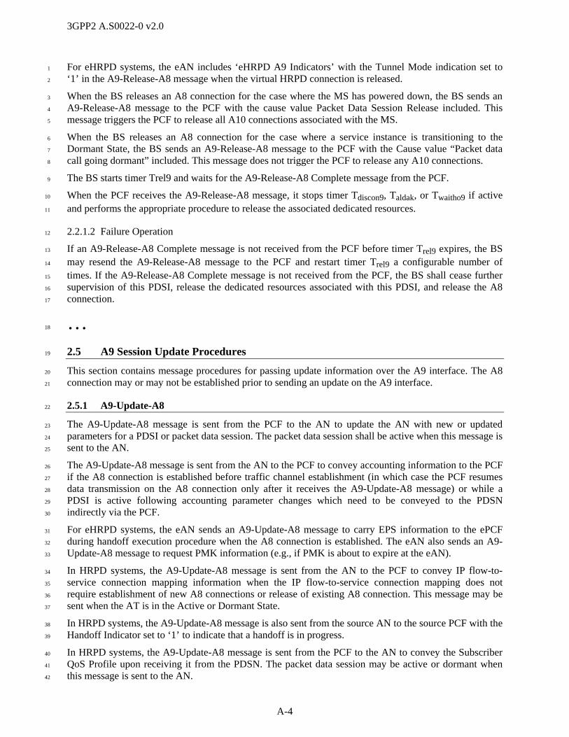
3GPP2 A.S0022-0 v2.0
A-4
For eHRPD systems, the eAN includes ‘eHRPD A9 Indicators’ with the Tunnel Mode indication set to 1
‘1’ in the A9-Release-A8 message when the virtual HRPD connection is released. 2
When the BS releases an A8 connection for the case where the MS has powered down, the BS sends an 3
A9-Release-A8 message to the PCF with the cause value Packet Data Session Release included. This 4
message triggers the PCF to release all A10 connections associated with the MS. 5
When the BS releases an A8 connection for the case where a service instance is transitioning to the 6
Dormant State, the BS sends an A9-Release-A8 message to the PCF with the Cause value “Packet data 7
call going dormant” included. This message does not trigger the PCF to release any A10 connections. 8
The BS starts timer Trel9 and waits for the A9-Release-A8 Complete message from the PCF. 9
When the PCF receives the A9-Release-A8 message, it stops timer Tdiscon9, Taldak, or Twaitho9 if active 10
and performs the appropriate procedure to release the associated dedicated resources. 11
2.2.1.2 Failure Operation 12
If an A9-Release-A8 Complete message is not received from the PCF before timer Trel9 expires, the BS 13
may resend the A9-Release-A8 message to the PCF and restart timer Trel9 a configurable number of 14
times. If the A9-Release-A8 Complete message is not received from the PCF, the BS shall cease further 15
supervision of this PDSI, release the dedicated resources associated with this PDSI, and release the A8 16
connection. 17
… 18
2.5 A9 Session Update Procedures 19
This section contains message procedures for passing update information over the A9 interface. The A8 20
connection may or may not be established prior to sending an update on the A9 interface. 21
2.5.1 A9-Update-A8 22
The A9-Update-A8 message is sent from the PCF to the AN to update the AN with new or updated 23
parameters for a PDSI or packet data session. The packet data session shall be active when this message is 24
sent to the AN. 25
The A9-Update-A8 message is sent from the AN to the PCF to convey accounting information to the PCF 26
if the A8 connection is established before traffic channel establishment (in which case the PCF resumes 27
data transmission on the A8 connection only after it receives the A9-Update-A8 message) or while a 28
PDSI is active following accounting parameter changes which need to be conveyed to the PDSN 29
indirectly via the PCF. 30
For eHRPD systems, the eAN sends an A9-Update-A8 message to carry EPS information to the ePCF 31
during handoff execution procedure when the A8 connection is established. The eAN also sends an A9-32
Update-A8 message to request PMK information (e.g., if PMK is about to expire at the eAN). 33
In HRPD systems, the A9-Update-A8 message is sent from the AN to the PCF to convey IP flow-to-34
service connection mapping information when the IP flow-to-service connection mapping does not 35
require establishment of new A8 connections or release of existing A8 connection. This message may be 36
sent when the AT is in the Active or Dormant State. 37
In HRPD systems, the A9-Update-A8 message is also sent from the source AN to the source PCF with the 38
Handoff Indicator set to ‘1’ to indicate that a handoff is in progress. 39
In HRPD systems, the A9-Update-A8 message is sent from the PCF to the AN to convey the Subscriber 40
QoS Profile upon receiving it from the PDSN. The packet data session may be active or dormant when 41
this message is sent to the AN. 42

3GPP2 A.S0022-0 v2.0
A-5
In HRPD systems, this message is also used to update the QoS for one or more specific IP flows. If there 1
is a Flow Profile ID with the value ‘0x0000’ in the U_QoS_SUB_BLOB for an IP flow, then the AN shall 2
inform the AT that the requested QoS_SUB_BLOB has been added but is invalid for this AN and the AT 3
should not activate the corresponding IP flow. Otherwise upon receipt of the updated QoS, the AN shall 4
change the granted QoS for the corresponding IP flow to the first acceptable Flow Profile ID in the list, 5
irrespective of the contents of the subscriber QoS Profile. A Flow Profile ID shall be considered 6
acceptable if it is supported by the AN, if it matches one of the Flow Profile IDs requested by the AT, and 7
if the call is not in inter-PCF handoff. The AN shall store the updated QoS information received from the 8
PCF together with the personality index in use at the time the update was received. Whenever the 9
specified personality index is in use, the AN shall use the stored QoS update to grant the QoS irrespective 10
of the contents of the subscriber QoS Profile. All updated QoS information stored in the AN for a given 11
IP flow is cleared when the corresponding IP flow is set to null (refer to C.S0087 [23]),6 regardless of the 12
personality in use. 13
Updated QoS information received from the PDSN (via the PCF) supersedes stored updated QoS 14
information previously received from the PDSN or from another AN (via A13 or A16). 15
In HRPD systems, this message may also be used by the HSGW to update the FLOW_PRIORITY for one 16
or more specific IP flows. For each IP Flow updated by the HSGW, the AN shall change the 17
FLOW_PRIORITY of that flow to the corresponding Updated FLOW_PRIORITY value in the element 18
that matches the corresponding Flow ID in the Forward/Reverse Flow Priority Update Information IE, 19
irrespective of the contents of the Subscriber QoS Profile. 20
The AN shall store the updated FLOW_PRIORITY value together with the personality index in use at the 21
time the Flow Priority update was received from the HSGW. Whenever the specified personality index is 22
in use, the AN shall use the stored FLOW_PRIORITY value to assign the priority to the flow irrespective 23
of the contents of the Subscriber QoS Profile. 24
Updated Flow Priority information received from the HSGW (via the PCF) supersedes stored Flow 25
Priority information previously received from the HSGW or from another AN (via A13 or A16). 26
In HRPD systems, this message is also used to release an IP flow by setting Flow Profile ID value to 27
‘0x0000’ in the Forward/Reverse Updated QoS Sub-BLOB for the IP flow that the PDNS wants to 28
release. The PDSN should not use this procedure for flow ID FFH and FEH. 29
In HRPD systems, this message is also used convey the ‘Emergency Services’ indication from the BS to 30
the PCF. 31
The AN may send an A9-Update-A8 message to the PCF to indicate if short data bursts may be sent to 32
the AT. The PCF may send an A9-Update-A8 message to the AN if the AT’s SDB capability is cached at 33
the PCF so the AN does not need to query the AT for its SDB capability. The AN may also send the A9-34
Update-A8 message to the PCF to indicate a successful Short Data Burst delivery to the AT if the PCF 35
was not informed previously that the SDB was delivered successfully to the AT. 36
The A9-Update-A8 message is also used to inform the PCF of an access or terminal authentication failure 37
at the MSC or at the AN-AAA for HRPD systems, following an access attempt by an AT undergoing 38
dormant handoff. The AN can also use this message to inform the PCF that an idle AT has powered 39
down. In these two cases, the PCF initiates the release of all A10 connections associated with the AT. 40
2.5.1.1 Successful Operation 41
If the A9-Update-A8 message is sent from the PCF to the AN to update packet data session parameters, or 42
to convey the subscriber QoS profile, the PCF includes the Cause element set to ‘Session parameter 43
update’ upon reception of any new or updated session parameters or the subscriber QoS profile from the 44
6 i.e., ProfileType = NULL in ReservationKKQoSRequestFwd or ReservationKKQoSRequestRev.

3GPP2 A.S0022-0 v2.0
A-6
PDSN. After sending the message to the AN, the PCF starts timer Tupd9 and waits for an A9-Update-A8 1
Ack message from the AN. 2
If the A9-Update-A8 message includes updated QoS and the AN does not have sufficient resources 3
available, then the AN may reject the A9-Update-A8 message by sending an A9-Update-A8 Ack message 4
with cause value “BS resources are not available”. 5
If the A9-Update-A8 message includes updated QoS and the AN only has resources available to comply 6
with the updated QoS for some of the specified flows, the AN may respond by sending an A9-Update-A8 7
Ack message with cause value “Partial QoS updated”. The AN informs the PCF of which QoS updates 8
were accepted and which were rejected using the IP flow mapping update procedure. 9
If the A9-Update-A8 message contains updated Flow Priority information, and the AN does not have 10
sufficient resources available to comply with the updated FLOW_PRIORITY for all or any of the 11
specified flows, then the AN may reject the A9-Update-A8 message by setting the cause value to “BS 12
resources are not available” in the A9-Update-A8 Ack message. 13
If the message is sent from the AN to the PCF to pass accounting or authentication information, the AN 14
shall set the Cause field to the appropriate value (1CH or 1EH), start timer Tupd9, and wait for an A9-15
Update-A8 Ack message from the PCF. 16
If the message is sent from the AN to the PCF or from the PCF to the AN to indicate if short data bursts 17
may be sent to the AT, the sending entity shall set the SDB/DoS Supported bit to ‘1’, set the Cause field 18
to ‘Capability update’ (1BH), start timer Tupd9 and wait for an A9-Update-A8 Ack message from the 19
receiving entity. 20
In HRPD systems, the A9-Update-A8 message includes the subscriber QoS profile. If the message is sent 21
from the PCF to the AN to covey the subscriber QoS profile, the PCF indicates the Cause field set to 22
‘Session Parameter Update’, start timer Tupd9, and wait for an A9-Update-A8 Ack message from the PCF. 23
In HRPD systems, if the AN receives an HRPD Emergency Indicator with the flow configuration request, 24
the AN sets the ‘Emergency Services’ indicator to ‘1’ in the A9-Update-A8 message sent to the PCF. 25
If the message is sent from the AN to the PCF to indicate a successful short data burst delivery to the AT, 26
the AN shall set the Cause field to ‘SDB successfully delivered’ (17H), start Tupd9 and wait for an A9-27
Update-A8 Ack message from the PCF. 28
For eHRPD, if the eAN sends an A9-Update-A8 message during the handoff execution procedure when 29
the A8 connection is established, then the A9-Update-A8 message includes the eHRPD A9 Indicators IE 30
indicating that the message is sent for handoff execution and the EPS information IE includes parameters 31
received via the S101 interface. In eHRPD systems, this message also includes the HSGW Information IE 32
to support sending PMK keys when they become available if they were unavailable when the eAN 33
requested them. 34
2.5.1.2 Failure Operation 35
When the message is sent from the PCF to the AN to update parameters for a PDSI, if Tupd9 expires, the 36
PCF may resend the A9-Update-A8 message to the AN and restart timer Tupd9 a configurable number of 37
times. If the A9-Update-A8-Ack message is not received from the AN, the session update procedure is 38
considered failed and the PCF notifies the PDSN. In the event of a failure, if an A8 connection was active 39
prior to the session update procedure, it shall remain connected. 40
When the message is sent from the AN to the PCF to pass accounting or authentication information, if an 41
A9-Update-A8 Ack message is not received from the PCF before timer Tupd9 expires, the AN may resend 42
the A9-Update-A8 message and restart timer Tupd9 a configurable number of times. If the 43
acknowledgment is not received from the PCF, the AN ceases sending this message, and commences 44
PDSI clearing. 45

3GPP2 A.S0022-0 v2.0
A-7
2.5.2 A9-Update-A8 Ack 1
For eHRPD, the ePCF sends the A9-Update-A8 Ack message including HSGW Information IE in 2
response to the A9-Update-A8 message when the ePCF receives HSGW related parameters over A11 3
interface. 4
… 5
3.1.1 A9-Setup-A8 6
This message is sent from the AN to the PCF to request the establishment of an A8 connection. In HRPD 7
systems, this message shall be used when performing any additions, deletions, remappings, and/or 8
changes in granted QoS of IP flows that require establishment of an A8 connection. 9
Information Element Section Reference
Element Direction Type
A9 Message Type [3], [4] AN -> PCF M
Call Connection Reference [3], [4] AN -> PCF O R
Correlation ID [3], [4] AN -> PCF Oa C
Mobile Identity (IMSI/ATI) [3], [4] AN -> PCF Ok C
Mobile Identity (ESN) [3], [4] AN -> PCF Ob C
CON_REF [3], [4] AN -> PCF Ol R
Quality of Service Parameters [3], [4] BS -> PCF Oc C
A9 Cell Identifier [3], [4] AN -> PCF O R
A8 Traffic ID [3], [4] AN -> PCF O R
Service Option [3], [4] AN -> PCF On,s R
A9 Indicators [3], [4] AN -> PCF O R
User Zone ID [3], [4] BS -> PCF Od C
IS-2000 Service Configuration Record [3], [4] BS -> PCF Oe C
Access Network Identifiers [3], [4] AN -> PCF Of C
PDSN Address [3], [4] AN -> PCF Og C
Sector ID [4] AN -> PCF Om C
Security Layer Packet [4] AN -> PCF On C
System Time [4] AN -> PCF Oo C
HRPD A9 Indicators [4] AN -> PCF Op C
Anchor PDSN Address [3], [4] BS -> PCF Oh C
Anchor P-P Address [3], [4] BS -> PCF Oi C
SR_ID [3], [4] AN -> PCF Oj C
Mobile Identity (MEID) [3], [4] AN -> PCF Ob C
Additional A8 Traffic ID [3], [4] AN -> PCF Oq,t C
Forward QoS Information [3], [4] AN -> PCF Or,t C
Reverse QoS Information [3], [4] AN -> PCF Or,t C
Assigning SC IP Address [4] AN -> PCF Ou C
Timers [4] AN -> PCF Ou C
eHRPD A9 Indicators 4.2.2 eAN -> ePCF Ov,w C
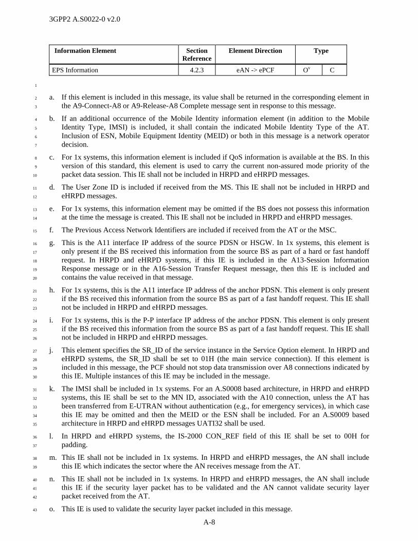
3GPP2 A.S0022-0 v2.0
A-8
Information Element Section Reference
Element Direction Type
EPS Information 4.2.3 eAN -> ePCF Ov C
1
a. If this element is included in this message, its value shall be returned in the corresponding element in 2
the A9-Connect-A8 or A9-Release-A8 Complete message sent in response to this message. 3
b. If an additional occurrence of the Mobile Identity information element (in addition to the Mobile 4
Identity Type, IMSI) is included, it shall contain the indicated Mobile Identity Type of the AT. 5
Inclusion of ESN, Mobile Equipment Identity (MEID) or both in this message is a network operator 6
decision. 7
c. For 1x systems, this information element is included if QoS information is available at the BS. In this 8
version of this standard, this element is used to carry the current non-assured mode priority of the 9
packet data session. This IE shall not be included in HRPD and eHRPD messages. 10
d. The User Zone ID is included if received from the MS. This IE shall not be included in HRPD and 11
eHRPD messages. 12
e. For 1x systems, this information element may be omitted if the BS does not possess this information 13
at the time the message is created. This IE shall not be included in HRPD and eHRPD messages. 14
f. The Previous Access Network Identifiers are included if received from the AT or the MSC. 15
g. This is the A11 interface IP address of the source PDSN or HSGW. In 1x systems, this element is 16
only present if the BS received this information from the source BS as part of a hard or fast handoff 17
request. In HRPD and eHRPD systems, if this IE is included in the A13-Session Information 18
Response message or in the A16-Session Transfer Request message, then this IE is included and 19
contains the value received in that message. 20
h. For 1x systems, this is the A11 interface IP address of the anchor PDSN. This element is only present 21
if the BS received this information from the source BS as part of a fast handoff request. This IE shall 22
not be included in HRPD and eHRPD messages. 23
i. For 1x systems, this is the P-P interface IP address of the anchor PDSN. This element is only present 24
if the BS received this information from the source BS as part of a fast handoff request. This IE shall 25
not be included in HRPD and eHRPD messages. 26
j. This element specifies the SR_ID of the service instance in the Service Option element. In HRPD and 27
eHRPD systems, the SR_ID shall be set to 01H (the main service connection). If this element is 28
included in this message, the PCF should not stop data transmission over A8 connections indicated by 29
this IE. Multiple instances of this IE may be included in the message. 30
k. The IMSI shall be included in 1x systems. For an A.S0008 based architecture, in HRPD and eHRPD 31
systems, this IE shall be set to the MN ID, associated with the A10 connection, unless the AT has 32
been transferred from E-UTRAN without authentication (e.g., for emergency services), in which case 33
this IE may be omitted and then the MEID or the ESN shall be included. For an A.S0009 based 34
architecture in HRPD and eHRPD messages UATI32 shall be used. 35
l. In HRPD and eHRPD systems, the IS-2000 CON_REF field of this IE shall be set to 00H for 36
padding. 37
m. This IE shall not be included in 1x systems. In HRPD and eHRPD messages, the AN shall include 38
this IE which indicates the sector where the AN receives message from the AT. 39
n. This IE shall not be included in 1x systems. In HRPD and eHRPD messages, the AN shall include 40
this IE if the security layer packet has to be validated and the AN cannot validate security layer 41
packet received from the AT. 42
o. This IE is used to validate the security layer packet included in this message. 43

3GPP2 A.S0022-0 v2.0
A-9
p. This IE shall not be included in 1x systems. In HRPD and eHRPD messages, the ePCF assumes that 1
all indicators are set to ‘0’ if this IE is not included in the message. 2
q. In HRPD and eHRPD systems, this IE shall include all auxiliary A8 connections (existing 3
connections to keep as well as new connections to establish) associated with the AT. A8 connections 4
to be released shall be omitted. 5
r. In HRPD and eHRPD systems, this IE shall include the IP flow-to-service connection mapping for all 6
IP flows in the specified direction (existing IP flows to keep as well as new IP flows to establish) 7
associated with the AT. IP flows to be released shall be omitted. Existing IP flows may be remapped 8
to a different A8 connection and may have a change in granted QoS. 9
s. In HRPD and eHRPD systems, this is the service option of the main service connection. 10
t. This IE is included if the information is available at the AN. 11
u. This IE is included if available when the target AN sends the A9-Setup-A8 message in case of active 12
handoff. This IE is not included in HRPD or eHRPD systems with SC/MM in the AN. 13
v. This IE is included if the eAN receives EPS parameters over S101 interface in case of E-UTRAN to 14
eHRPD pre-registration and handoff execution. 15
w. This IE is included with the PMK Indicator set to ‘1’ if the eAN supports GKE and is requesting 16
PMK information from the HSGW. This IE is not required for a system with SC/MM in the ePCF. 17
The following table shows the bitmap layout for the A9-Setup-A8 message. 18
3.1.1 A9-Setup-A8
7 6 5 4 3 2 1 0 Octet
A9 Message Type = [01H] 1
Call Connection Reference: A9 Element Identifier = [3FH] 1
Length = [08H] 2
(MSB) Market ID = <any value> 3
(LSB) 4
(MSB) Generating Entity ID = <any value> 5
(LSB) 6
(MSB) Call Connection Reference = <any value> 7
8
9
(LSB) 10
Correlation ID: A9 Element Identifier = [13H] 1
Length = [04H] 2
(MSB) Correlation Value = <any value> 3
4
5
(LSB) 6
Mobile Identity (IMSI/ATI): A9 Element Identifier = [0DH] 1
Length = [06H-08H] (10-15 digits) 2

3GPP2 A.S0022-0 v2.0
A-10
3.1.1 A9-Setup-A8
7 6 5 4 3 2 1 0 Octet
Identity Digit 1 = [0H-9H] (BCD) Odd/even Indicator = [1,0]
Type of Identity = [110 (IMSI) = 111 (ATI)]
3
Identity Digit 3 = [0H-9H] (BCD) Identity Digit 2 = [0H-9H] (BCD) 4
… …
Identity Digit N+1 = [0H-9H] (BCD) Identity Digit N = [0H-9H] (BCD) n
Identity Digit N+3 = [0H-9H] (BCD) (if odd number of digits)
= [1111] (if even number of digits)
Identity Digit N+2 = [0H-9H] (BCD) n+1
History Ind = [0H (Current)] ATI Type = [2H (UATI 32)] n+2
(MSB) UATIColorCode = <any value> (LSB) n+3
(MSB) UATI024 = <any value> n+4
n+5
(LSB) n+6
Mobile Identity (ESN): A9 Element Identifier = [0DH] 1
Length = [05H] 2
Identity Digit 1 = [0000] Odd/even Indicator
= [0]
Type of Identity = [101] (ESN) 3
(MSB) ESN = <any value> 4
5
6
(LSB) 7
CON_REF: A9 Element Identifier = [01H] 1
Length = [01H] 2
IS-2000 CON_REF = [00H – FFH] 3
Quality of Service Parameters: A9 Element Identifier = [07H] 1
Length = [01H] 2
Reserved = [0000] Non-Assured Mode Packet Priority = [0000 – 1101]
3
A9 Cell Identifier: A9 Element Identifier = [06H] 1
Length = [06H] 2
Cell Identification Discriminator = [07H] 3
(MSB) MSCID = <any value> 4
5
(LSB) 6
(MSB) Cell = [001H-FFFH] 7
(LSB) Sector = [0H-FH] (0H = Omni) 8
A8 Traffic ID: A9 Element Identifier = [08H] 1

3GPP2 A.S0022-0 v2.0
A-11
3.1.1 A9-Setup-A8
7 6 5 4 3 2 1 0 Octet
Length = [0CH] 2
A8 transport protocol stack = [01H] (GRE/IP) 3
(MSB) Protocol Type = [88 81H] (Unstructured byte stream) 4
(LSB) 5
(MSB) Key = <any value> 6
7
8
(LSB) 9
Address Type = [01H] (IPv4) 10
(MSB) IP Address = <any value> 11
12
13
(LSB) 14
Service Option: A9 Element Identifier = [03H] 1
(MSB) Service Option 2
= [00 21H (3G High Speed Packet Data), 00 3CH (Link Layer Assisted Header Removal) 00 3DH (Link Layer Assisted RObust Header Compression)] for 1x systems
= [00 3BH (HRPD Main Service Connection)] for HRPD systems
(LSB) 3
A9 Indicators: A9 Element Identifier = [05H] 1
Length = [02H] 2
QoS Mode
= [0, 1]
Packet Boundary Supported
= [0] (ignored)
GRE Segment. Supported
= [0,1]
SDB/DoS Supported
= [0,1]
CCPD Mode =
[0,1]
EmergencyServices =
[0,1]
Data Ready
Indicator = [0,1]
Handoff Indicator = [0, 1]
3
Reserved = 0
Reserved = 0
Reserved = 0
Reserved = 0
Reserved = 0
Reserved = 0
Reserved = 0
Buffer Transfer = [0, 1]
4
User Zone ID: A9 Element Identifier = [02H] 1
Length = [02H] 2
(MSB) UZID = <any value> 3
(LSB) 4
IS-2000 Service Configuration Record: A9 Element Identifier = [0EH] 1
Bit-Exact Length – Octet Count = <variable> 2
Reserved = [0000 0]
Bit-Exact Length – Fill Bits = [000 – 111]
3
(MSB) 4
IS-2000 Service Configuration Record Content = <any value> …

3GPP2 A.S0022-0 v2.0
A-12
3.1.1 A9-Setup-A8
7 6 5 4 3 2 1 0 Octet
Seventh Fill Bit –
if needed = [0 (if
used as a fill bit)]
Sixth Fill Bit – if needed = [0 (if
used as a fill bit)]
Fifth Fill Bit – if needed = [0 (if
used as a fill bit)]
Fourth Fill Bit – if needed= [0 (if
used as a fill bit)]
Third Fill Bit – if needed = [0 (if
used as a fill bit)]
Second Fill Bit – if needed= [0 (if
used as a fill bit)]
First Fill Bit – if needed = [0 (if
used as a fill bit)]
k
Access Network Identifiers: A9 Element Identifier = [20H] 1
Length = [05H] 2
Reserved = [0]
(MSB) SID = <any value> 3
(LSB) 4
(MSB) NID = <any value> 5
(LSB) 6
PZID = <any value> 7
PDSN Address: A9 Element Identifier = [14H] 1
Length = [04H] 2
(MSB) PDSN Address = <any value> 3
4
5
(LSB) 6
Sector ID: A9 Element Identifier = [88H] 1
Length = [11H] 2
Sector ID Discriminator = [01H (Sector ID128)] 3
(MSB) Sector ID = <any value> 4
5
… …
(LSB) 19
Security Layer Packet: A9 Element Identifier = [89H] 1
Length = [variable] 2
(MSB) Security Layer Packet 3
4
… …
(LSB) n
System Time: A9 Element Identifier = [8CH] 1
Length = [08H] 2
(MSB) CDMA System Time = <any value> 3
4
… …
(LSB) 10

3GPP2 A.S0022-0 v2.0
A-13
3.1.1 A9-Setup-A8
7 6 5 4 3 2 1 0 Octet
HRPD A9 Indicators: A9 Element Identifier = [8BH] 1
Length = [01H] 2
Reserved = [0000 0] Handoff Type
= [0, 1]
Default Session
Indicator = [0]
Session Information Required =
[0, 1]
3
Anchor PDSN Address: A9 Element Identifier = [30H] 1
Length = [04H] 2
(MSB) Anchor PDSN Address = <any value> 3
4
5
(LSB) 6
Anchor P-P Address: A9 Element Identifier = [40H] 1
Length = [04H] 2
(MSB) Serving P-P IP Address = <any value> 3
4
5
(LSB) 6
SR_ID: A9 Element Identifier = [0BH] 1
Length = [01H] 2
SR_ID = [01H – 1FH] 3
Mobile Identity (MEID): A9 Element Identifier = [0DH] 1
Length = [08H] 2
MEID Hex Digit 1 = [0H-FH] Odd/Even Indicator =
‘0’
Type of Identity = [001] (MEID)
3
MEID Hex Digit 3 = [0H-FH] MEID Hex Digit 2 = [0H-FH] 4
MEID Hex Digit 5 = [0H-FH] MEID Hex Digit 4 = [0H-FH] 5
MEID Hex Digit 7 = [0H-FH] MEID Hex Digit 6 = [0H-FH] 6
MEID Hex Digit 9 = [0H-FH] MEID Hex Digit 8 = [0H-FH] 7
MEID Hex Digit 11 = [0H-FH] MEID Hex Digit 10 = [0H-FH] 8
MEID Hex Digit 13 = [0H-FH] MEID Hex Digit 12 = [0H-FH] 9
Fill = [FH] MEID Hex Digit 14 = [0H-FH] 10
Additional A8 Traffic ID: A9 Element Identifier = [92H] 1
Length = [variable] 2
A8 Traffic ID Entry { 1-30 :
Entry Length = [0FH] n
SR_ID = [02H-1FH] n+1
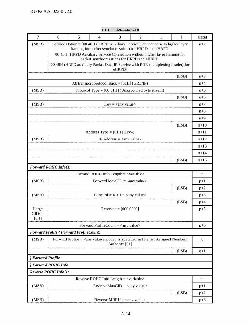
3GPP2 A.S0022-0 v2.0
A-14
3.1.1 A9-Setup-A8
7 6 5 4 3 2 1 0 Octet
(MSB) Service Option = [00 40H (HRPD Auxiliary Service Connection with higher layer framing for packet synchronization) for HRPD and eHRPD,
00 43H (HRPD Auxiliary Service Connection without higher layer framing for packet synchronization) for HRPD and eHRPD,
00 48H (HRPD auxiliary Packet Data IP Service with PDN multiplexing header) for eHRPD]
n+2
(LSB) n+3
A8 transport protocol stack = [01H] (GRE/IP) n+4
(MSB) Protocol Type = [88 81H] (Unstructured byte stream) n+5
(LSB) n+6
(MSB) Key = <any value> n+7
n+8
n+9
(LSB) n+10
Address Type = [01H] (IPv4) n+11
(MSB) IP Address = <any value> n+12
n+13
n+14
(LSB) n+15
Forward ROHC Info{1:
Forward ROHC Info Length = <variable> p
(MSB) Forward MaxCID = <any value> p+1
(LSB) p+2
(MSB) Forward MRRU = <any value> p+3
(LSB) p+4
Large CIDs =
[0,1]
Reserved = [000 0000] p+5
Forward ProfileCount = <any value> p+6
Forward Profile { Forward ProfileCount:
(MSB) Forward Profile = <any value encoded as specified in Internet Assigned Numbers Authority [31]
q
(LSB) q+1
} Forward Profile
} Forward ROHC Info
Reverse ROHC Info{1:
Reverse ROHC Info Length = <variable> p
(MSB) Reverse MaxCID = <any value> p+1
(LSB) p+2
(MSB) Reverse MRRU = <any value> p+3
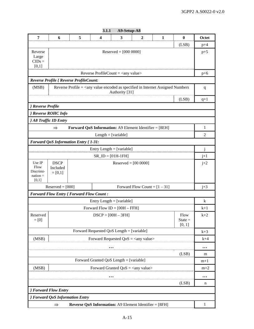
3GPP2 A.S0022-0 v2.0
A-15
3.1.1 A9-Setup-A8
7 6 5 4 3 2 1 0 Octet
(LSB) p+4
Reverse Large
CIDs = [0,1]
Reserved = [000 0000] p+5
Reverse ProfileCount = <any value> p+6
Reverse Profile { Reverse ProfileCount:
(MSB) Reverse Profile = <any value encoded as specified in Internet Assigned Numbers Authority [31]
q
(LSB) q+1
} Reverse Profile
} Reverse ROHC Info
} A8 Traffic ID Entry
Forward QoS Information: A9 Element Identifier = [8EH] 1
Length = [variable] 2
Forward QoS Information Entry { 1-31:
Entry Length = [variable] j
SR_ID = [01H-1FH] j+1
Use IP Flow
Discrimi-nation =
[0,1]
DSCP Included = [0,1]
Reserved = [00 0000] j+2
Reserved = [000] Forward Flow Count = [1 – 31] j+3
Forward Flow Entry { Forward Flow Count :
Entry Length = [variable] k
Forward Flow ID = [00H – FFH] k+1
Reserved = [0]
DSCP = [00H – 3FH] Flow State = [0, 1]
k+2
Forward Requested QoS Length = [variable] k+3
(MSB) Forward Requested QoS = <any value> k+4
… …
(LSB) m
Forward Granted QoS Length = [variable] m+1
(MSB) Forward Granted QoS = <any value> m+2
… …
(LSB) n
} Forward Flow Entry
} Forward QoS Information Entry
Reverse QoS Information: A9 Element Identifier = [8FH] 1

3GPP2 A.S0022-0 v2.0
A-16
3.1.1 A9-Setup-A8
7 6 5 4 3 2 1 0 Octet
Length = [variable] 2
Reverse QoS Information Entry { 1-31:
Entry Length = [variable] j
SR_ID = [01H-1FH] j+1
Reserved = [000] Reverse Flow Count = [1 – 31] j+2
Reverse Flow Entry { Reverse Flow Count :
Entry Length = [variable] k
Reverse Flow ID = [00H – FFH] k+1
Reserved = [0000 000] Flow State = [0, 1]
k+2
Reverse Requested QoS Length = [variable] k+3
(MSB) Reverse Requested QoS = <any value> k+4
… …
(LSB) m
Reverse Granted QoS Length = [variable] m+1
(MSB) Reverse Granted QoS = <any value> m+2
… …
(LSB) n
} Reverse Flow Entry
} Reverse QoS Information Entry
Assigning SC IP Address: A9 Element Identifier = [96H] 1
Length = [04H] 2
(MSB) Assigning SC IP Address 3
4
5
(LSB) 6
Timers: A9 Element Identifier = [97H] 1
Length = [04H] 2
Timer { 1:
Timer Type = [01H (Tsclose) ] n
Timer Length = [05H] n+1
(MSB) Starting Time n+2
… n+3
n+4
n+5
(LSB) n+6
} Timer
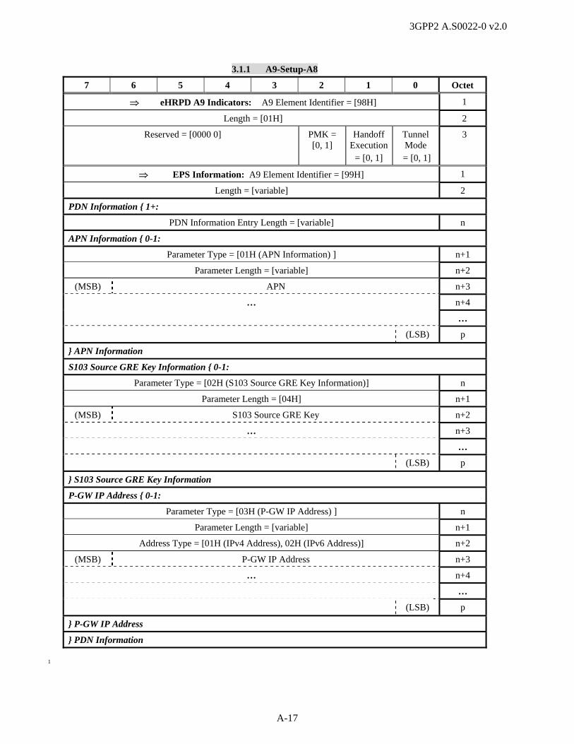
3GPP2 A.S0022-0 v2.0
A-17
3.1.1 A9-Setup-A8
7 6 5 4 3 2 1 0 Octet
eHRPD A9 Indicators: A9 Element Identifier = [98H] 1
Length = [01H] 2
Reserved = [0000 0] PMK = [0, 1]
Handoff Execution
= [0, 1]
Tunnel Mode
= [0, 1]
3
EPS Information: A9 Element Identifier = [99H] 1
Length = [variable] 2
PDN Information { 1+:
PDN Information Entry Length = [variable] n
APN Information { 0-1:
Parameter Type = [01H (APN Information) ] n+1
Parameter Length = [variable] n+2
(MSB) APN n+3
… n+4
…
(LSB) p
} APN Information
S103 Source GRE Key Information { 0-1:
Parameter Type = [02H (S103 Source GRE Key Information)] n
Parameter Length = [04H] n+1
(MSB) S103 Source GRE Key n+2
… n+3
…
(LSB) p
} S103 Source GRE Key Information
P-GW IP Address { 0-1:
Parameter Type = [03H (P-GW IP Address) ] n
Parameter Length = [variable] n+1
Address Type = [01H (IPv4 Address), 02H (IPv6 Address)] n+2
(MSB) P-GW IP Address n+3
… n+4
…
(LSB) p
} P-GW IP Address
} PDN Information
1
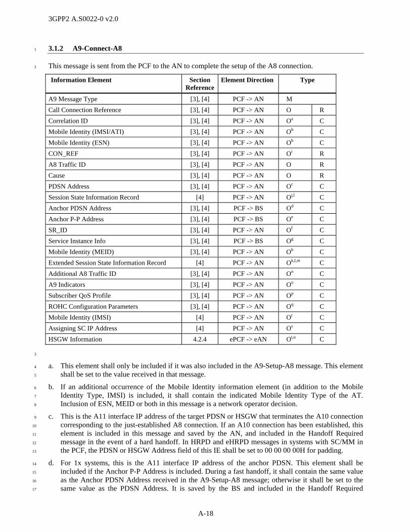
3GPP2 A.S0022-0 v2.0
A-18
3.1.2 A9-Connect-A8 1
This message is sent from the PCF to the AN to complete the setup of the A8 connection. 2
Information Element Section Reference
Element Direction Type
A9 Message Type [3], [4] PCF -> AN M
Call Connection Reference [3], [4] PCF -> AN O R
Correlation ID [3], [4] PCF -> AN Oa C
Mobile Identity (IMSI/ATI) [3], [4] PCF -> AN Oh C
Mobile Identity (ESN) [3], [4] PCF -> AN Ob C
CON_REF [3], [4] PCF -> AN Oi R
A8 Traffic ID [3], [4] PCF -> AN O R
Cause [3], [4] PCF -> AN O R
PDSN Address [3], [4] PCF -> AN Oc C
Session State Information Record [4] PCF -> AN Oj,l C
Anchor PDSN Address [3], [4] PCF -> BS Od C
Anchor P-P Address [3], [4] PCF -> BS Oe C
SR_ID [3], [4] PCF -> AN Of C
Service Instance Info [3], [4] PCF -> BS Og C
Mobile Identity (MEID) [3], [4] PCF -> AN Ob C
Extended Session State Information Record [4] PCF -> AN Ok,l,m C
Additional A8 Traffic ID [3], [4] PCF -> AN On C
A9 Indicators [3], [4] PCF -> AN Oo C
Subscriber QoS Profile [3], [4] PCF -> AN Op C
ROHC Configuration Parameters [3], [4] PCF -> AN Oq C
Mobile Identity (IMSI) [4] PCF -> AN Or C
Assigning SC IP Address [4] PCF -> AN Os C
HSGW Information 4.2.4 ePCF -> eAN Ot,u C
3
a. This element shall only be included if it was also included in the A9-Setup-A8 message. This element 4
shall be set to the value received in that message. 5
b. If an additional occurrence of the Mobile Identity information element (in addition to the Mobile 6
Identity Type, IMSI) is included, it shall contain the indicated Mobile Identity Type of the AT. 7
Inclusion of ESN, MEID or both in this message is a network operator decision. 8
c. This is the A11 interface IP address of the target PDSN or HSGW that terminates the A10 connection 9
corresponding to the just-established A8 connection. If an A10 connection has been established, this 10
element is included in this message and saved by the AN, and included in the Handoff Required 11
message in the event of a hard handoff. In HRPD and eHRPD messages in systems with SC/MM in 12
the PCF, the PDSN or HSGW Address field of this IE shall be set to 00 00 00 00H for padding. 13
d. For 1x systems, this is the A11 interface IP address of the anchor PDSN. This element shall be 14
included if the Anchor P-P Address is included. During a fast handoff, it shall contain the same value 15
as the Anchor PDSN Address received in the A9-Setup-A8 message; otherwise it shall be set to the 16
same value as the PDSN Address. It is saved by the BS and included in the Handoff Required 17

3GPP2 A.S0022-0 v2.0
A-19
message in the event of a fast handoff. During a fast handoff, inclusion of this field indicates 1
acceptance of the fast handoff. This IE shall not be included in HRPD and eHRPD messages. 2
e. For 1x systems, this is the IP address for establishing P-P connections to the serving PDSN. This 3
element shall be included if fast handoff is supported and if the value was received from the PDSN. It 4
is saved by the BS and included in the Handoff Required message in the event of a fast handoff. 5
During a fast handoff, inclusion of this field indicates acceptance of the fast handoff. This IE shall not 6
be included in HRPD and eHRPD messages. 7
f. In 1x systems, this element specifies the SR_ID of the connected service instance. In HRPD and 8
eHRPD systems, the SR_ID shall be set to 01H (the main service connection). If this element is 9
included in this message, the PCF should not stop data transmission over A8 connections indicated by 10
this IE. Multiple instances of this IE may be included in the message. 11
g. For 1x systems, this element identifies all service instances for which the PCF has an A10 connection, 12
excluding the service instance identified by the SR_ID information element. This element shall be 13
included on transition of the packet data session to the Active State, i.e., when the first A8 connection 14
of a packet data session is being established, but not during handoff (i.e., the Handoff Indicator in the 15
A9-Setup-A8 message was set to ‘1’). This IE shall not be included for HRPD and eHRPD messages. 16
h. The IMSI shall be included in 1x systems. For an A.S0008 based architecture, this IE shall be set to 17
the MN ID, associated with the A10 connection, in HRPD and eHRPD messages, unless the AT has 18
been transferred from E-UTRAN without authentication (e.g., for emergency services), in which case 19
this IE may be omitted and then the MEID or the ESN shall be included. For an A.S0009 based 20
architecture in HRPD and eHRPD messages, UATI32 shall be used. 21
i. The IS-2000 CON_REF field of this IE shall be set to 00H for padding, in HRPD and eHRPD 22
messages. 23
j. This IE shall not be included in 1x systems. In HRPD and eHRPD messages, this IE shall be included 24
when the PCF decides that session information needs to be transferred to the AN. Multiple instances 25
of this IE may be included, where one instance of this IE contains one SSIR as specified in C.S0087 26
[23]. 27
k. This IE is included when the information on multiple personalities is available. Multiple instances of 28
this IE may be included, where one instance of this IE contains one SSIR for an HRPD and eHRPD 29
personality that is not the main personality, as specified in C.S0087 [23]. Multiple instances of this IE 30
shall be sorted in order of increasing personality index. 31
l. Attributes with default values shall not be sent to the target node. If an attribute is not contained in the 32
SSIR, the target node shall assume that the missing attribute(s) have the default values (specified for 33
each attribute in each protocol). This IE is not included in HRPD or eHRPD systems with SC/MM in 34
the AN. 35
m. SSIRs of protocol types with HardLink subtype shall not be sent to the target node unless specified 36
otherwise. SSIRs of Session Configuration Protocol Types may be sent even if the subtype is set to 37
HardLink. 38
n. This IE shall be included if it was included in the corresponding A9-Setup-A8 message. The number 39
of A8 connections included in this IE shall be same as the number of connections included in the 40
Additional A8 Traffic ID IE in the corresponding A9-Setup-A8 message. 41
o. This IE shall be included if the PCF has enabled packet boundary indications. 42
p. This IE is included if this information is available. 43
q. This IE is included if this information is received from the PDSN or HSGW. It conveys the ROHC 44
configuration parameters supported by the PDSN or HSGW when using ROHC on SO67 with header 45
compression at the PDSN or HSGW. 46

3GPP2 A.S0022-0 v2.0
A-20
r. This IE shall only be included for session transfer over A16 interface in HRPD and eHRPD messages, 1
and shall include IMSI, unless the AT has been transferred from E-UTRAN without authentication 2
(e.g., for emergency services), in which case this IE may be omitted and then the MEID or the ESN 3
shall be included. This IE is not included in HRPD or eHRPD systems with SC/MM in the AN. 4
s. This IE shall be included when the PCF that sends this message manages LCM_UATI and indicates 5
IP address of SC managing LCM_UATI. Otherwise, this IE shall not be included. This IE is not 6
included in HRPD or eHRPD systems with SC/MM in the AN. 7
t. This IE is included if the ePCF receives HSGW parameters over A11 interface in case of E-UTRAN 8
to eHRPD handoff execution while A8 connection is disconnected. 9
u. This IE is included if the ePCF receives PMK information from the HSGW. 10
The following table shows the bitmap layout for the A9-Connect-A8 message. 11
3.1.2 A9-Connect-A8
7 6 5 4 3 2 1 0 Octet
A9 Message Type = [02H] 1
Call Connection Reference: A9 Element Identifier = [3FH] 1
Length = [08H] 2
(MSB) Market ID = <any value> 3
(LSB) 4
(MSB) Generating Entity ID = <any value> 5
(LSB) 6
(MSB) Call Connection Reference = <any value> 7
8
9
(LSB) 10
Correlation ID: A9 Element Identifier = [13H] 1
Length = [04H] 2
(MSB) Correlation Value = <any value> 3
4
5
(LSB) 6
Mobile Identity (IMSI/ATI): A9 Element Identifier = [0DH] 1
Length = [06H-08H] (10-15 digits) 2
Identity Digit 1 = [0H-9H] (BCD) Odd/even Indicator= [1,0]
Type of Identity = [110 (IMSI) = 111 (ATI)]
3
Identity Digit 3 = [0H-9H] (BCD) Identity Digit 2 = [0H-9H] (BCD) 4
… …
Identity Digit N+1 = [0H-9H] (BCD) Identity Digit N = [0H-9H] (BCD) n
Identity Digit N+3 = [0H-9H] (BCD) (if odd number of digits)
= [1111] (if even number of digits)
Identity Digit N+2 = [0H-9H] (BCD) n+1
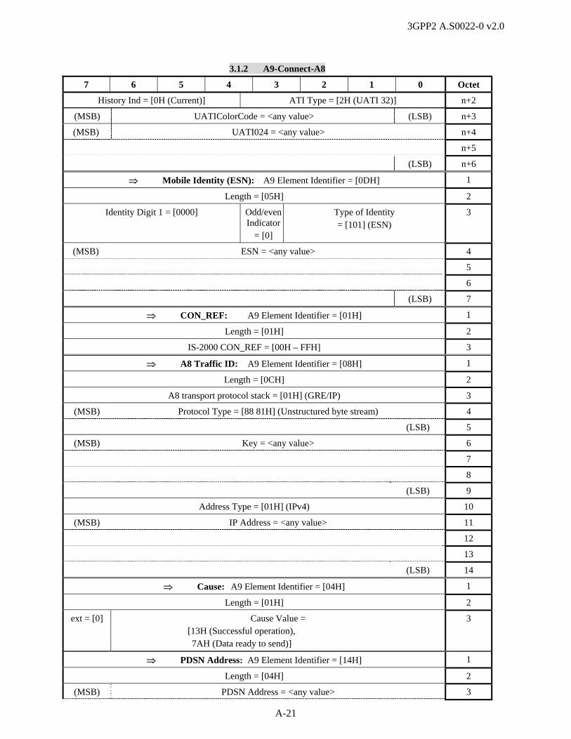
3GPP2 A.S0022-0 v2.0
A-21
3.1.2 A9-Connect-A8
7 6 5 4 3 2 1 0 Octet
History Ind = [0H (Current)] ATI Type = [2H (UATI 32)] n+2
(MSB) UATIColorCode = <any value> (LSB) n+3
(MSB) UATI024 = <any value> n+4
n+5
(LSB) n+6
Mobile Identity (ESN): A9 Element Identifier = [0DH] 1
Length = [05H] 2
Identity Digit 1 = [0000] Odd/even Indicator
= [0]
Type of Identity = [101] (ESN)
3
(MSB) ESN = <any value> 4
5
6
(LSB) 7
CON_REF: A9 Element Identifier = [01H] 1
Length = [01H] 2
IS-2000 CON_REF = [00H – FFH] 3
A8 Traffic ID: A9 Element Identifier = [08H] 1
Length = [0CH] 2
A8 transport protocol stack = [01H] (GRE/IP) 3
(MSB) Protocol Type = [88 81H] (Unstructured byte stream) 4
(LSB) 5
(MSB) Key = <any value> 6
7
8
(LSB) 9
Address Type = [01H] (IPv4) 10
(MSB) IP Address = <any value> 11
12
13
(LSB) 14
Cause: A9 Element Identifier = [04H] 1
Length = [01H] 2
ext = [0] Cause Value = [13H (Successful operation), 7AH (Data ready to send)]
3
PDSN Address: A9 Element Identifier = [14H] 1
Length = [04H] 2
(MSB) PDSN Address = <any value> 3
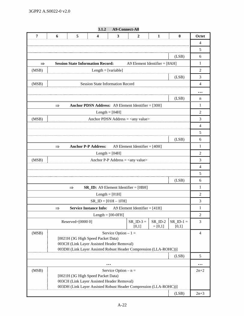
3GPP2 A.S0022-0 v2.0
A-22
3.1.2 A9-Connect-A8
7 6 5 4 3 2 1 0 Octet
4
5
(LSB) 6
Session State Information Record: A9 Element Identifier = [8AH] 1
(MSB) Length = [variable] 2
(LSB) 3
(MSB) Session State Information Record 4
…
(LSB) n
Anchor PDSN Address: A9 Element Identifier = [30H] 1
Length = [04H] 2
(MSB) Anchor PDSN Address = <any value> 3
4
5
(LSB) 6
Anchor P-P Address: A9 Element Identifier = [40H] 1
Length = [04H] 2
(MSB) Anchor P-P Address = <any value> 3
4
5
(LSB) 6
SR_ID: A9 Element Identifier = [0BH] 1
Length = [01H] 2
SR_ID = [01H – 1FH] 3
Service Instance Info: A9 Element Identifier = [41H] 1
Length = [00-0FH] 2
Reserved=[0000 0] SR_ID-3 = [0,1]
SR_ID-2 = [0,1]
SR_ID-1 = [0,1]
3
(MSB) Service Option – 1 = [0021H (3G High Speed Packet Data) 003CH (Link Layer Assisted Header Removal) 003DH (Link Layer Assisted Robust Header Compression (LLA-ROHC))]
4
(LSB) 5
… …
(MSB) Service Option – n = [0021H (3G High Speed Packet Data) 003CH (Link Layer Assisted Header Removal) 003DH (Link Layer Assisted Robust Header Compression (LLA-ROHC))]
2n+2
(LSB) 2n+3

3GPP2 A.S0022-0 v2.0
A-23
3.1.2 A9-Connect-A8
7 6 5 4 3 2 1 0 Octet
Mobile Identity (MEID): A9 Element Identifier = [0DH] 1
Length = [08H] 2
MEID Hex Digit 1 = [0H-FH] Odd/EvenIndicator
= ‘0’
Type of Identity = [001] (MEID)
3
MEID Hex Digit 3 = [0H-FH] MEID Hex Digit 2 = [0H-FH] 4
MEID Hex Digit 5 = [0H-FH] MEID Hex Digit 4 = [0H-FH] 5
MEID Hex Digit 7 = [0H-FH] MEID Hex Digit 6 = [0H-FH] 6
MEID Hex Digit 9 = [0H-FH] MEID Hex Digit 8 = [0H-FH] 7
MEID Hex Digit 11 = [0H-FH] MEID Hex Digit 10 = [0H-FH] 8
MEID Hex Digit 13 = [0H-FH] MEID Hex Digit 12 = [0H-FH] 9
Fill = [FH] MEID Hex Digit 14 = [0H-FH] 10
Extended Session State Information Record: A9 Element Identifier = [8DH] 1
(MSB) Length = [variable] 2
(LSB) 3
Reserved Personality Index 4
(MSB) Session State Information Record 5
…
(LSB) n
Additional A8 Traffic ID: A9 Element Identifier = [92H] 1
Length = [variable] 2
A8 Traffic ID Entry { 1-30 :
Entry Length = [0FH] n
SR_ID = [02H-1FH] n+1
(MSB) Service Option = [00 40H (HRPD Auxiliary Service Connection with higher layer framing for packet synchronization) for HRPD and eHRPD,
00 43H (HRPD Auxiliary Service Connection without higher layer framing for packet synchronization) for HRPD and eHRPD,
00 48H (HRPD auxiliary Packet Data IP Service with PDN multiplexing header) for eHRPD]
n+2
(LSB) n+3
A8 transport protocol stack = [01H] (GRE/IP) n+4
(MSB) Protocol Type = [88 81H] (Unstructured byte stream) n+5
(LSB) n+6
(MSB) Key = <any value> n+7
n+8
n+9
(LSB) n+10
Address Type = [01H] (IPv4) n+11
(MSB) IP Address = <any value> n+12
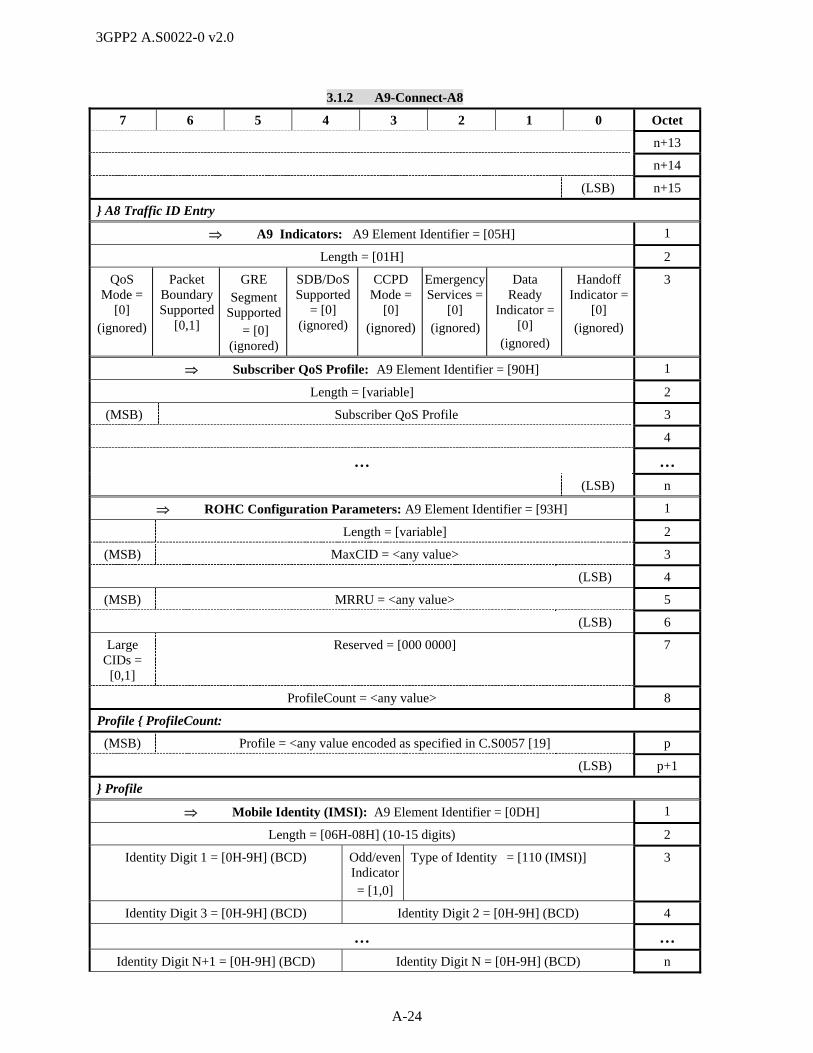
3GPP2 A.S0022-0 v2.0
A-24
3.1.2 A9-Connect-A8
7 6 5 4 3 2 1 0 Octet
n+13
n+14
(LSB) n+15
} A8 Traffic ID Entry
A9 Indicators: A9 Element Identifier = [05H] 1
Length = [01H] 2
QoS Mode =
[0] (ignored)
Packet Boundary Supported
[0,1]
GRE Segment
Supported = [0]
(ignored)
SDB/DoS Supported
= [0] (ignored)
CCPD Mode =
[0] (ignored)
Emergency Services =
[0] (ignored)
Data Ready
Indicator = [0]
(ignored)
Handoff Indicator =
[0] (ignored)
3
Subscriber QoS Profile: A9 Element Identifier = [90H] 1
Length = [variable] 2
(MSB) Subscriber QoS Profile 3
4
… …
(LSB) n
ROHC Configuration Parameters: A9 Element Identifier = [93H] 1
Length = [variable] 2
(MSB) MaxCID = <any value> 3
(LSB) 4
(MSB) MRRU = <any value> 5
(LSB) 6
Large CIDs =
[0,1]
Reserved = [000 0000] 7
ProfileCount = <any value> 8
Profile { ProfileCount:
(MSB) Profile = <any value encoded as specified in C.S0057 [19] p
(LSB) p+1
} Profile
Mobile Identity (IMSI): A9 Element Identifier = [0DH] 1
Length = [06H-08H] (10-15 digits) 2
Identity Digit 1 = [0H-9H] (BCD) Odd/even Indicator= [1,0]
Type of Identity = [110 (IMSI)] 3
Identity Digit 3 = [0H-9H] (BCD) Identity Digit 2 = [0H-9H] (BCD) 4
… …
Identity Digit N+1 = [0H-9H] (BCD) Identity Digit N = [0H-9H] (BCD) n
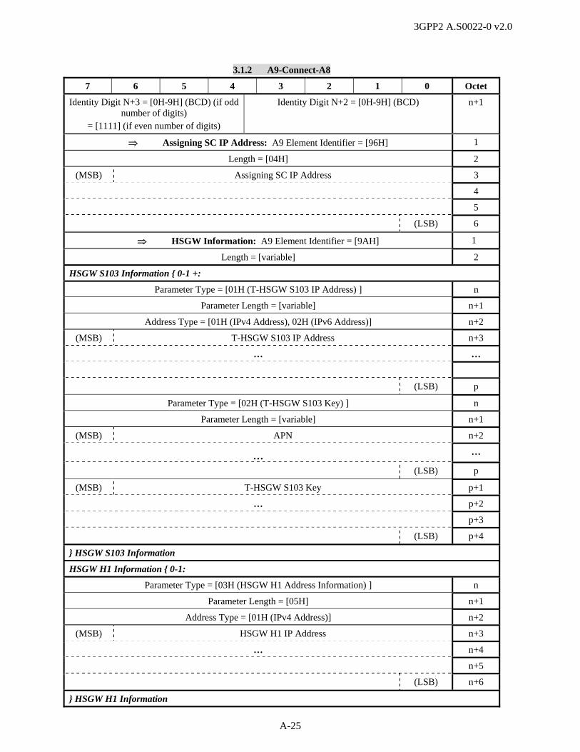
3GPP2 A.S0022-0 v2.0
A-25
3.1.2 A9-Connect-A8
7 6 5 4 3 2 1 0 Octet
Identity Digit N+3 = [0H-9H] (BCD) (if odd number of digits)
= [1111] (if even number of digits)
Identity Digit N+2 = [0H-9H] (BCD) n+1
Assigning SC IP Address: A9 Element Identifier = [96H] 1
Length = [04H] 2
(MSB) Assigning SC IP Address 3
4
5
(LSB) 6
HSGW Information: A9 Element Identifier = [9AH] 1
Length = [variable] 2
HSGW S103 Information { 0-1 +:
Parameter Type = [01H (T-HSGW S103 IP Address) ] n
Parameter Length = [variable] n+1
Address Type = [01H (IPv4 Address), 02H (IPv6 Address)] n+2
(MSB) T-HSGW S103 IP Address n+3
… …
(LSB) p
Parameter Type = [02H (T-HSGW S103 Key) ] n
Parameter Length = [variable] n+1
(MSB) APN n+2
… …
(LSB) p
(MSB) T-HSGW S103 Key p+1
… p+2
p+3
(LSB) p+4
} HSGW S103 Information
HSGW H1 Information { 0-1:
Parameter Type = [03H (HSGW H1 Address Information) ] n
Parameter Length = [05H] n+1
Address Type = [01H (IPv4 Address)] n+2
(MSB) HSGW H1 IP Address n+3
… n+4
n+5
(LSB) n+6
} HSGW H1 Information

3GPP2 A.S0022-0 v2.0
A-26
3.1.2 A9-Connect-A8
7 6 5 4 3 2 1 0 Octet
PMK Information { 0-1:
Parameter Type = [04H (PMK Information)] n
Parameter Length = [variable] n+1
PMK Count = <any value> n+2
PMK { PMK Count+1:
PMK Length = [variable] p
(MSB) PMK = <any value> p+1
…
(LSB) q
(MSB) PMK Lifetime = <any value> q+1
q+2
q+3
(LSB) q+4
} PMK } PMK Information
… 1
3.2.1 A9-Release-A8 2
This message is sent from the eAN to the ePCF to release an A8 connection. In HRPD systems, this 3
message shall be used when performing any additions, deletions, remappings, and/or changes in granted 4
QoS of IP flows that require release of one or more A8 connections but no A8 connection establishment. 5
(For A8 connection release with A8 connection establishment, refer to section 3.1.1.). 6
7
Information Element Section Reference
Element Direction Type
A9 Message Type [3], [4] AN -> PCF M
Call Connection Reference [3], [4] AN -> PCF O R
Correlation ID [3], [4] AN -> PCF Oa C
Mobile Identity (IMSI/ATI) [3], [4] AN -> PCF Of C
Mobile Identity (ESN) [3], [4] AN -> PCF Ob C
CON_REF [3], [4] AN -> PCF Og R
A8 Traffic ID [3], [4] AN -> PCF Oh R
Cause [3], [4] AN -> PCF Oc R
Active Connection Time in Seconds [3], [4] AN -> PCF Od R
SR_ID [3], [4] AN -> PCF Oe,h C
Mobile Identity (MEID) [3], [4] AN -> PCF Ob C
Additional A8 Traffic ID [3], [4] AN -> PCF Oi C
Forward QoS Information [3], [4] AN -> PCF Oj C
Reverse QoS Information [3], [4] AN -> PCF Oj C
eHRPD A9 Indicators 4.2.2 eAN -> ePCF Ok C

3GPP2 A.S0022-0 v2.0
A-27
1
a. This element shall be included if it was also included in the A9-Disconnect-A8 message. This 2
element shall be set to the value received in that message. If this element was not included in that 3
message, it may be included in this message. 4
b. If an additional occurrence of the Mobile Identity information element (in addition to the Mobile 5
Identity Type, IMSI) is included, it shall contain the indicated Mobile Identity Type of the MS. 6
Inclusion of ESN, MEID or both in this message is a network operator decision. 7
c. The cause value Normal Call Release indicates that the PDSI has been released and therefore the A10 8
resources associated with this service instance should be dropped. If the cause value indicates Packet 9
Data Session Release, all services have been released by the MS and therefore all A10 connections 10
associated with the MS shall be released. If the cause value indicates a hard handoff failure, the ePCF 11
shall not release any A10 connection associated with the packet data session (intra-PCF hard handoff 12
failure). In HRPD systems, any cause value other than “Partial connection release” indicates that all 13
A8 connections associated with the AT shall be released. 14
d. This element shall be included to indicate the active connection time for a traffic channel. For HRPD 15
systems, this IE indicates the current value of the active connection time for the traffic channel at the 16
time this message is sent. 17
e. In 1x systems, this element specifies the SR_ID of the service instance to be released. 18
f. The IMSI shall be included in 1x systems. For an A.S0008 based architecture, this IE shall be set to 19
the MN ID, associated with the A10 connection, in HRPD and eHRPD messages, unless the AT has 20
been transferred from E-UTRAN without authentication (e.g., for emergency services), in which case 21
this IE may be omitted and then the MEID or the ESN shall be included. For an A.S0009 based 22
architecture in HRPD and eHRPD messages, UATI32 shall be used. 23
g. The IS-2000 CON_REF field of this IE shall be set to 00H for padding, in HRPD messages. 24
h. In HRPD systems, the SR_ID shall be set to 01H (the main service connection). If this element is 25
included in this message, the ePCF should not stop data transmission over A8 connections indicated 26
by this IE. Multiple instances of this IE may be included in the message. 27
i. In HRPD systems, this IE shall be included if the Cause value is set to “Partial connection release”. It 28
specifies all auxiliary A8 connections to keep. A8 connections to be released shall be omitted. This IE 29
shall be omitted when releasing all A8 connections for the AT. 30
j. In HRPD systems, this IE shall include the IP flow-to-service connection mapping for all IP flows in 31
the specified direction (IP flows to keep) associated with the AT. IP flows to be released shall be 32
omitted. Existing IP flows may be remapped to a different A8 connection and may have a change in 33
granted QoS. 34
k. This IE is included if the eAT is connected to the eHRPD system via the S101 tunnel. 35
36
The following table shows the bitmap layout for the A9-Release-A8 message. 37
3.2.1 A9-Release-A8
7 6 5 4 3 2 1 0 Octet
A9 Message Type = [04H] 1
Call Connection Reference: A9 Element Identifier = [3FH] 1
Length = [08H] 2
(MSB) Market ID = <any value> 3
(LSB) 4

3GPP2 A.S0022-0 v2.0
A-28
3.2.1 A9-Release-A8
7 6 5 4 3 2 1 0 Octet
(MSB) Generating Entity ID = <any value> 5
(LSB) 6
(MSB) Call Connection Reference = <any value> 7
8
9
(LSB) 10
Correlation ID: A9 Element Identifier = [13H] 1
Length = [04H] 2
(MSB) Correlation Value = <any value> 3
4
5
(LSB) 6
Mobile Identity (IMSI): A9 Element Identifier = [0DH] 1
Length = [06H-08H] (10-15 digits) 2
Identity Digit 1 = [0H-9H] (BCD) Odd/even Indicator= [1,0]
Type of Identity = [110] (IMSI)
3
Identity Digit 3 = [0H-9H] (BCD) Identity Digit 2 = [0H-9H] (BCD) 4
… …
Identity Digit N+1 = [0H-9H] (BCD) Identity Digit N = [0H-9H] (BCD) n
Identity Digit N+3 = [0H-9H] (BCD) (if odd number of digits)
= [1111] (if even number of digits)
Identity Digit N+2 = [0H-9H] (BCD) n+1
Mobile Identity (ESN): A9 Element Identifier = [0DH] 1
Length = [05H] 2
Identity Digit 1 = [0000] Odd/even Indicator
= [0]
Type of Identity = [101] (ESN)
3
(MSB) ESN = <any value> 4
5
6
(LSB) 7
CON_REF: A9 Element Identifier = [01H] 1
Length = [01H] 2
IS-2000 CON_REF = [00H – FFH] 3
A8 Traffic ID: A9 Element Identifier = [08H] 1
Length = [0CH] 2
A8 transport protocol stack = [01H] (GRE/IP) 3
(MSB) Protocol Type = [88 81H] (Unstructured byte stream) 4

3GPP2 A.S0022-0 v2.0
A-29
3.2.1 A9-Release-A8
7 6 5 4 3 2 1 0 Octet
(LSB) 5
(MSB) Key = <any value> 6
7
8
(LSB) 9
Address Type = [01H] (IPv4) 10
(MSB) IP Address = <any value> 11
12
13
(LSB) 14
Cause: A9 Element Identifier = [04H] 1
Length = [01H] 2
ext = [0] Cause Value = [01H (Partial connection release), 0BH (Handoff successful), 0FH (Packet data session release), 10H (Packet call going dormant), 14H (Normal call release), 1AH (Authentication failure), 1DH (Hard handoff failure), 1FH (Air link lost), 20H (Equipment failure)]
3
Active Connection Time in Seconds: A9 Element Identifier = [0AH] 1
Length = [04H] 2
(MSB) Active Connection Time = [00 00 00 00H – FF FF FF FFH] 3
4
… 5
(LSB) 6
SR_ID: A9 Element Identifier = [0BH] 1
Length = [01H] 2
SR_ID = [01H – 1FH] 3
Mobile Identity (MEID): A9 Element Identifier = [0DH] 1
Length = [08H] 2
MEID Hex Digit 1 = [0H-FH] Odd/Even Indicator =
‘0’
Type of Identity = [001] (MEID)
3
MEID Hex Digit 3 = [0H-FH] MEID Hex Digit 2 = [0H-FH] 4
MEID Hex Digit 5 = [0H-FH] MEID Hex Digit 4 = [0H-FH] 5
MEID Hex Digit 7 = [0H-FH] MEID Hex Digit 6 = [0H-FH] 6
MEID Hex Digit 9 = [0H-FH] MEID Hex Digit 8 = [0H-FH] 7
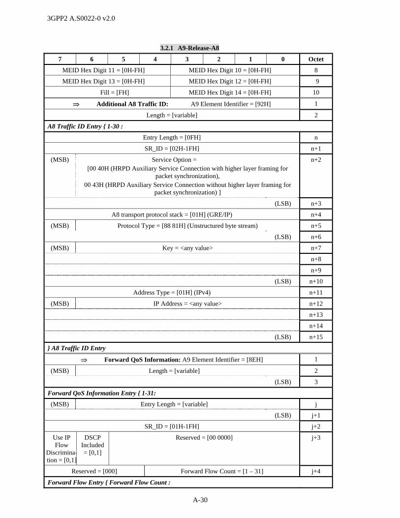
3GPP2 A.S0022-0 v2.0
A-30
3.2.1 A9-Release-A8
7 6 5 4 3 2 1 0 Octet
MEID Hex Digit 11 = [0H-FH] MEID Hex Digit 10 = [0H-FH] 8
MEID Hex Digit 13 = [0H-FH] MEID Hex Digit 12 = [0H-FH] 9
Fill = [FH] MEID Hex Digit 14 = [0H-FH] 10
Additional A8 Traffic ID: A9 Element Identifier = [92H] 1
Length = [variable] 2
A8 Traffic ID Entry { 1-30 :
Entry Length = [0FH] n
SR_ID = [02H-1FH] n+1
(MSB) Service Option = [00 40H (HRPD Auxiliary Service Connection with higher layer framing for
packet synchronization), 00 43H (HRPD Auxiliary Service Connection without higher layer framing for
packet synchronization) ]
n+2
(LSB) n+3
A8 transport protocol stack = [01H] (GRE/IP) n+4
(MSB) Protocol Type = [88 81H] (Unstructured byte stream) n+5
(LSB) n+6
(MSB) Key = <any value> n+7
n+8
n+9
(LSB) n+10
Address Type = [01H] (IPv4) n+11
(MSB) IP Address = <any value> n+12
n+13
n+14
(LSB) n+15
} A8 Traffic ID Entry
Forward QoS Information: A9 Element Identifier = [8EH] 1
(MSB) Length = [variable] 2
(LSB) 3
Forward QoS Information Entry { 1-31:
(MSB) Entry Length = [variable] j
(LSB) j+1
SR_ID = [01H-1FH] j+2
Use IP Flow
Discrimina-tion = [0,1]
DSCP Included= [0,1]
Reserved = [00 0000] j+3
Reserved = [000] Forward Flow Count = [1 – 31] j+4
Forward Flow Entry { Forward Flow Count :

3GPP2 A.S0022-0 v2.0
A-31
3.2.1 A9-Release-A8
7 6 5 4 3 2 1 0 Octet
Entry Length = [variable] k
Forward Flow ID = [00H – FFH] k+1
Reserved = [0]
DSCP = [00H – 3FH] Flow State = [0, 1]
k+2
Forward Requested QoS Length = [variable] k+2
(MSB) Forward Requested QoS = <any value> k+3
… …
(LSB) m
Forward Granted QoS Length = [variable] m+1
(MSB) Forward Granted QoS = <any value> m+2
… …
(LSB) n
} Forward Flow Entry
} Forward QoS Information Entry
Reverse QoS Information: A9 Element Identifier = [8FH] 1
(MSB) Length = [variable] 2
(LSB) 3
Reverse QoS Information Entry { 1-31:
(MSB) Entry Length = [variable] j
(LSB) j+1
SR_ID = [01H-1FH] j+2
Reserved = [000] Reverse Flow Count = [1 – 31] j+3
Reverse Flow Entry { Reverse Flow Count :
Entry Length = [variable] k
Reverse Flow ID = [00H – FFH] k+1
Reserved = [0000 000] Flow State = [0, 1]
k+2
Reverse Requested QoS Length = [variable] k+2
(MSB) Reverse Requested QoS = <any value> k+3
… …
(LSB) m
Reverse Granted QoS Length = [variable] m+1
(MSB) Reverse Granted QoS = <any value> m+2
… …
(LSB) n
} Reverse Flow Entry
} Reverse QoS Information Entry

3GPP2 A.S0022-0 v2.0
A-32
3.2.1 A9-Release-A8
7 6 5 4 3 2 1 0 Octet
eHRPD A9 Indicators: A9 Element Identifier = [98H] 1
Length = [01H] 2
Reserved = [0000 0] PMK = [0, 1]
(ignored)
Handoff Execution
= [0, 1] (ignored)
Tunnel Mode
= [0, 1]
3
… 1
3.5 A9 Session Update Procedures 2
3
3.5.1 A9-Update-A8 4
This message is sent from the AN to the PCF to indicate a change to the session airlink parameters, 5
whether SDBs may be sent to an AT, whether an SDB was successfully delivered to an AT, or to indicate 6
an authentication failure. This message is also sent from the PCF to the AN to transfer new or updated 7
packet data session parameters to the AN. In HRPD and eHRPD systems, this message shall be used 8
when performing any additions, deletions, remappings, changes in granted QoS, and/or changes in flow 9
state of IP flows, provided no A8 connections are established and no existing A8 connections are 10
released. In HRPD and eHRPD systems, this message is also used to support QoS update or flow priority 11
update by the PDSN or HSGW. 12
Information Element Section Reference
Element Direction Type
A9 Message Type [3], [4] AN <-> PCF M
Call Connection Reference [3], [4] AN <-> PCF O R
Correlation ID [3], [4] AN <-> PCF Oa C
Mobile Identity (IMSI/ATI) [3], [4] AN <-> PCF Oi C
Mobile Identity (ESN) [3], [4] AN -> PCF Ob C
IS-2000 Service Configuration Record [3], [4] BS -> PCF Oc,j C
Service Option [3], [4] AN -> PCF Oc,l C
User Zone ID [3], [4] BS -> PCF Oc,j C
Quality of Service Parameters [3], [4] BS -> PCF Oc,j C
Cause [3], [4] AN <-> PCF O R
RN-PDIT [3], [4] AN <- PCF Od C
SR_ID [3], [4] AN <-> PCF Oe C
Mobile Identity (MEID) [3], [4] AN -> PCF Ob C
A9 Indicators [3], [4] AN <-> PCF Of C
PDSN Address [3], [4] PCF -> AN Og C
Anchor PDSN Address [3], [4] PCF -> BS Oh,j C
Anchor P-P Address [3], [4] PCF -> BS Oh,j C
Forward QoS Information [3], [4] AN -> PCF Ok C
Reverse QoS Information [3], [4] AN -> PCF Ok C

3GPP2 A.S0022-0 v2.0
A-33
Information Element Section Reference
Element Direction Type
Subscriber QoS Profile [3], [4] PCF -> AN Oh C
Forward QoS Update Information [3], [4] PCF -> AN Om,n C
Reverse QoS Update Information [3], [4] PCF -> AN Om,n C
eHRPD A9 Indicators 4.2.2 eAN -> ePCF Oo C
EPS Information 4.2.3 eAN -> ePCF Oo C
HSGW Information 4.2.4 ePCF -> eAN Op C
Forward Flow Priority Update Information [3], [4] PCF -> AN Oq C
Reverse Flow Priority Update Information [3], [4] PCF -> AN Oq C
1
a. If this element is included in this message, its value shall be returned in the corresponding element in 2
the A9-Update-A8-Ack message sent in response to this message. 3
b. If an additional occurrence of the Mobile Identity information element (in addition to the Mobile 4
Identity Type, IMSI) is included, it shall contain the indicated Mobile Identity Type of the AT. 5
Inclusion of ESN, MEID or both in this message is a network operator decision. 6
c. These elements are required when the message is sent from the AN to the PCF unless the message is 7
used to indicate Dormant Power down or Authentication Failure. 8
d. This element is included in the message when the PDSN or HSGW has sent the parameter to the PCF. 9
e. In 1x systems, this element specifies the SR_ID of the service instance in the Service Option element. 10
In HRPD and eHRPD systems, the SR_ID shall be set to 01H (the main service connection). If this 11
element is included in this message, the PCF should not stop data transmission over A8 connections 12
indicated by this IE. Multiple instances of this IE may be included in the message. 13
f. This element is included when used to indicate if the PDSI supports Short Data bursts. In HRPD 14
systems, this element may also be used to provide Emergency Services indication from the BS to the 15
PCF. 16
g. This element contains the A11 IP address of the PDSN or HSGW terminating the A10 connection. 17
This element is included when A10 connections were established with a new PDSN or HSGW during 18
an active packet data session. 19
h. These IEs are included if this information is received from the PDSN. 20
i. The IMSI shall be included in 1x systems. For an A.S0008 based architecture, this IE shall be set to 21
the MN ID, associated with the A10 connection, in HRPD and eHRPD messages, unless the AT has 22
been transferred from E-UTRAN without authentication (e.g., for emergency services), in which case 23
this IE may be omitted and then the MEID or the ESN shall be included. For an A.S0009 based 24
architecture in HRPD and eHRPD messages, UATI32 shall be used. 25
j. This IE shall not be included in HRPD and eHRPD messages. 26
k. In HRPD and eHRPD systems, this IE shall include the IP flow-to-service connection mapping for all 27
IP flows in the specified direction (existing IP flows to keep as well as new IP flows to establish) 28
associated with the AT. IP flows to be released shall be omitted. Existing IP flows may be remapped 29
to a different A8 connection and may have a change in granted QoS. 30
l. In HRPD and eHRPD systems, this IE shall contain information for the main service connection. 31
m. In HRPD and eHRPD systems, this IE is used when the PDSN or HSGW updates QoS for one or 32
more IP flows in the specified direction. If there is a Flow Profile ID with the value ‘0x0000’ in the 33
U_QoS_SUB_BLOB for an IP flow, then the AN shall inform the AT that the requested 34
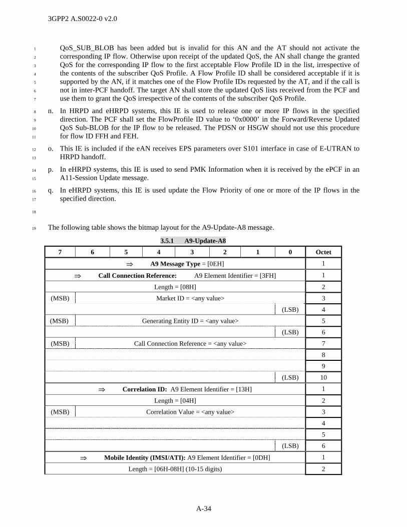
3GPP2 A.S0022-0 v2.0
A-34
QoS_SUB_BLOB has been added but is invalid for this AN and the AT should not activate the 1
corresponding IP flow. Otherwise upon receipt of the updated QoS, the AN shall change the granted 2
QoS for the corresponding IP flow to the first acceptable Flow Profile ID in the list, irrespective of 3
the contents of the subscriber QoS Profile. A Flow Profile ID shall be considered acceptable if it is 4
supported by the AN, if it matches one of the Flow Profile IDs requested by the AT, and if the call is 5
not in inter-PCF handoff. The target AN shall store the updated QoS lists received from the PCF and 6
use them to grant the QoS irrespective of the contents of the subscriber QoS Profile. 7
n. In HRPD and eHRPD systems, this IE is used to release one or more IP flows in the specified 8
direction. The PCF shall set the FlowProfile ID value to ‘0x0000’ in the Forward/Reverse Updated 9
QoS Sub-BLOB for the IP flow to be released. The PDSN or HSGW should not use this procedure 10
for flow ID FFH and FEH. 11
o. This IE is included if the eAN receives EPS parameters over S101 interface in case of E-UTRAN to 12
HRPD handoff. 13
p. In eHRPD systems, this IE is used to send PMK Information when it is received by the ePCF in an 14
A11-Session Update message. 15
q. In eHRPD systems, this IE is used update the Flow Priority of one or more of the IP flows in the 16
specified direction. 17
18
The following table shows the bitmap layout for the A9-Update-A8 message. 19
3.5.1 A9-Update-A8
7 6 5 4 3 2 1 0 Octet
A9 Message Type = [0EH] 1
Call Connection Reference: A9 Element Identifier = [3FH] 1
Length = [08H] 2
(MSB) Market ID = <any value> 3
(LSB) 4
(MSB) Generating Entity ID = <any value> 5
(LSB) 6
(MSB) Call Connection Reference = <any value> 7
8
9
(LSB) 10
Correlation ID: A9 Element Identifier = [13H] 1
Length = [04H] 2
(MSB) Correlation Value = <any value> 3
4
5
(LSB) 6
Mobile Identity (IMSI/ATI): A9 Element Identifier = [0DH] 1
Length = [06H-08H] (10-15 digits) 2

3GPP2 A.S0022-0 v2.0
A-35
3.5.1 A9-Update-A8
7 6 5 4 3 2 1 0 Octet
Identity Digit 1 = [0H-9H] (BCD) Odd/even Indicator= [1,0]
Type of Identity = [110 (IMSI),
111 (ATI)]
3
Identity Digit 3 = [0H-9H] (BCD) Identity Digit 2 = [0H-9H] (BCD) 4
… …
Identity Digit N+1 = [0H-9H] (BCD) Identity Digit N = [0H-9H] (BCD) n
Identity Digit N+3 = [0H-9H] (BCD) (if odd number of digits)
= [1111] (if even number of digits)
Identity Digit N+2 = [0H-9H] (BCD) n+1
History Ind = [0H (Current)] ATI Type = [2H (UATI 32)] n+2
(MSB) UATIColorCode = <any value> (LSB) n+3
(MSB) UATI024 = <any value> n+4
n+5
(LSB) n+6
Mobile Identity (ESN): A9 Element Identifier = [0DH] 1
Length = [05H] 2
Identity Digit 1 = [0000] Odd/even Indicator
= [0]
Type of Identity = [101] (ESN)
3
(MSB) ESN = <any value> 4
5
6
(LSB) 7
IS-2000 Service Configuration Record: A9 Element Identifier = [0EH] 1
Bit-Exact Length – Octet Count = <variable> 2
Reserved = [0000 0]
Bit-Exact Length – Fill Bits = [000 – 111]
3
(MSB) IS-2000 Service Configuration Record Content = <any value> 4
…
Seventh Fill Bit – if needed = [0 (if
used as a fill bit)]
Sixth Fill Bit – if needed = [0 (if
used as a fill bit)]
Fifth Fill Bit – if needed = [0 (if
used as a fill bit)]
Fourth Fill Bit – if needed= [0 (if
used as a fill bit)]
Third Fill Bit
– if needed = [0 (if used as
a fill bit)]
Second Fill Bit – if needed= [0 (if
used as a fill bit)]
First Fill Bit – if needed = [0 (if used as
a fill bit)]
k
Service Option: A9 Element Identifier = [03H] 1
(MSB) Service Option 2
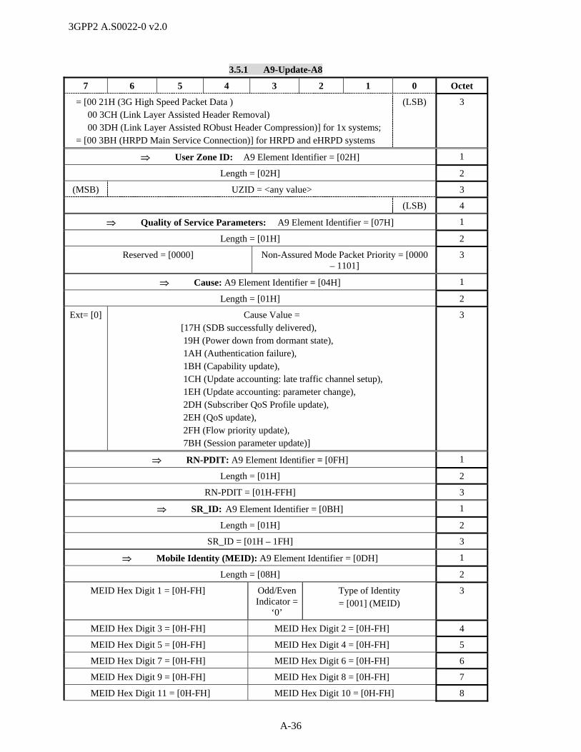
3GPP2 A.S0022-0 v2.0
A-36
3.5.1 A9-Update-A8
7 6 5 4 3 2 1 0 Octet
= [00 21H (3G High Speed Packet Data ) 00 3CH (Link Layer Assisted Header Removal) 00 3DH (Link Layer Assisted RObust Header Compression)] for 1x systems;
= [00 3BH (HRPD Main Service Connection)] for HRPD and eHRPD systems
(LSB) 3
User Zone ID: A9 Element Identifier = [02H] 1
Length = [02H] 2
(MSB) UZID = <any value> 3
(LSB) 4
Quality of Service Parameters: A9 Element Identifier = [07H] 1
Length = [01H] 2
Reserved = [0000] Non-Assured Mode Packet Priority = [0000 – 1101]
3
Cause: A9 Element Identifier = [04H] 1
Length = [01H] 2
Ext= [0] Cause Value = [17H (SDB successfully delivered), 19H (Power down from dormant state), 1AH (Authentication failure), 1BH (Capability update), 1CH (Update accounting: late traffic channel setup), 1EH (Update accounting: parameter change), 2DH (Subscriber QoS Profile update), 2EH (QoS update), 2FH (Flow priority update), 7BH (Session parameter update)]
3
RN-PDIT: A9 Element Identifier = [0FH] 1
Length = [01H] 2
RN-PDIT = [01H-FFH] 3
SR_ID: A9 Element Identifier = [0BH] 1
Length = [01H] 2
SR_ID = [01H – 1FH] 3
Mobile Identity (MEID): A9 Element Identifier = [0DH] 1
Length = [08H] 2
MEID Hex Digit 1 = [0H-FH] Odd/Even Indicator =
‘0’
Type of Identity = [001] (MEID)
3
MEID Hex Digit 3 = [0H-FH] MEID Hex Digit 2 = [0H-FH] 4
MEID Hex Digit 5 = [0H-FH] MEID Hex Digit 4 = [0H-FH] 5
MEID Hex Digit 7 = [0H-FH] MEID Hex Digit 6 = [0H-FH] 6
MEID Hex Digit 9 = [0H-FH] MEID Hex Digit 8 = [0H-FH] 7
MEID Hex Digit 11 = [0H-FH] MEID Hex Digit 10 = [0H-FH] 8

3GPP2 A.S0022-0 v2.0
A-37
3.5.1 A9-Update-A8
7 6 5 4 3 2 1 0 Octet
MEID Hex Digit 13 = [0H-FH] MEID Hex Digit 12 = [0H-FH] 9
Fill = [FH] MEID Hex Digit 14 = [0H-FH] 10
A9 Indicators: A9 Element Identifier = [05H] 1
Length = [01H] 2
QoS Mode [0,1]
(Ignored)
Packet Boundary Supported
[0,1] (Ignored)
GRE Segment. Supported
[0,1] (Ignored)
SDB/DoS Supported
= [0,1]
CCPD Mode =
[0,1] (Ignored)
Emergency Services =
[0,1]
Data Ready
Indicator = [0,1]
(Ignored)
Handoff Indicator = [0,1]
3
PDSN Address: A9 Element Identifier = [14H] 1
Length = [04H] 2
(MSB) PDSN Address = <any value> 3
4
5
6
Anchor PDSN Address: A9 Element Identifier = [30H] 1
Length = [04H] 2
(MSB) Anchor PDSN Address = <any value> 3
4
5
(LSB) 6
Anchor P-P Address: A9 Element Identifier = [40H] 1
Length = [04H] 2
(MSB) Serving P-P IP Address = <any value> 3
4
5
(LSB) 6
Forward QoS Information: A9 Element Identifier = [8EH] 1
Length = [variable] 2
Forward QoS Information Entry { 1-31:
Entry Length = [variable] j
SR_ID = [01H-1FH] j+1
Use IP Flow
Discrimination = [0,1]
DSCP Included=
[0,1]
Reserved = [00 0000] j+2
Reserved = [000] Forward Flow Count = [1 – 31] j+3
Forward Flow Entry { Forward Flow Count :
Entry Length = [variable] k

3GPP2 A.S0022-0 v2.0
A-38
3.5.1 A9-Update-A8
7 6 5 4 3 2 1 0 Octet
Forward Flow ID = [00H – FFH] k+1
Reserved DSCP Flow State = [0, 1]
k+2
Forward Requested QoS Length = [variable] k+3
(MSB) Forward Requested QoS = <any value> k+4
… …
(LSB) m
Forward Granted QoS Length = [variable] m+1
(MSB) Forward Granted QoS = <any value> m+2
… …
(LSB) n
} Forward Flow Entry
} Forward QoS Information Entry
Reverse QoS Information: A9 Element Identifier = [8FH] 1
Length = [variable] 2
Reverse QoS Information Entry { 1-31:
Entry Length = [variable] j
SR_ID = [01H-1FH] j+1
Reserved = [000] Reverse Flow Count = [1 – 31] j+2
Reverse Flow Entry {Reverse Flow Count :
Entry Length = [variable] k
Reverse Flow ID = [00H – FFH] k+1
Reserved = [0000 000] Flow State = [0, 1]
k+2
Reverse Requested QoS Length = [variable] k+3
(MSB) Reverse Requested QoS = <any value> k+4
… …
(LSB) m
Reverse Granted QoS Length = [variable] m+1
(MSB) Reverse Granted QoS = <any value> m+2
… …
(LSB) n
} Reverse Flow Entry
} Reverse QoS Information Entry
Subscriber QoS Profile: A9 Element Identifier = [90H] 1
Length = [variable] 2
(MSB) Subscriber QoS Profile 3
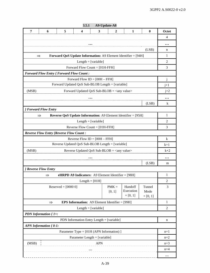
3GPP2 A.S0022-0 v2.0
A-39
3.5.1 A9-Update-A8
7 6 5 4 3 2 1 0 Octet
4
… …
(LSB) n
Forward QoS Update Information: A9 Element Identifier = [94H] 1
Length = [variable] 2
Forward Flow Count = [01H-FFH] 3
Forward Flow Entry { Forward Flow Count :
Forward Flow ID = [00H – FFH] j
Forward Updated QoS Sub-BLOB Length = [variable] j+1
(MSB) Forward Updated QoS Sub-BLOB = <any value> j+2
… …
(LSB) k
} Forward Flow Entry
Reverse QoS Update Information: A9 Element Identifier = [95H] 1
Length = [variable] 2
Reverse Flow Count = [01H-FFH] 3
Reverse Flow Entry {Reverse Flow Count :
Reverse Flow ID = [00H – FFH] k
Reverse Updated QoS Sub-BLOB Length = [variable] k+1
(MSB) Reverse Updated QoS Sub-BLOB = <any value> k+2
… …
(LSB) m
} Reverse Flow Entry
eHRPD A9 Indicators: A9 Element Identifier = [98H] 1
Length = [01H] 2
Reserved = [0000 0] PMK = [0, 1]
Handoff Execution
= [0, 1]
Tunnel Mode
= [0, 1]
3
EPS Information: A9 Element Identifier = [99H] 1
Length = [variable] 2
PDN Information { 1+:
PDN Information Entry Length = [variable] n
APN Information { 0-1:
Parameter Type = [01H (APN Information) ] n+1
Parameter Length = [variable] n+2
(MSB) APN n+3
… n+4
…
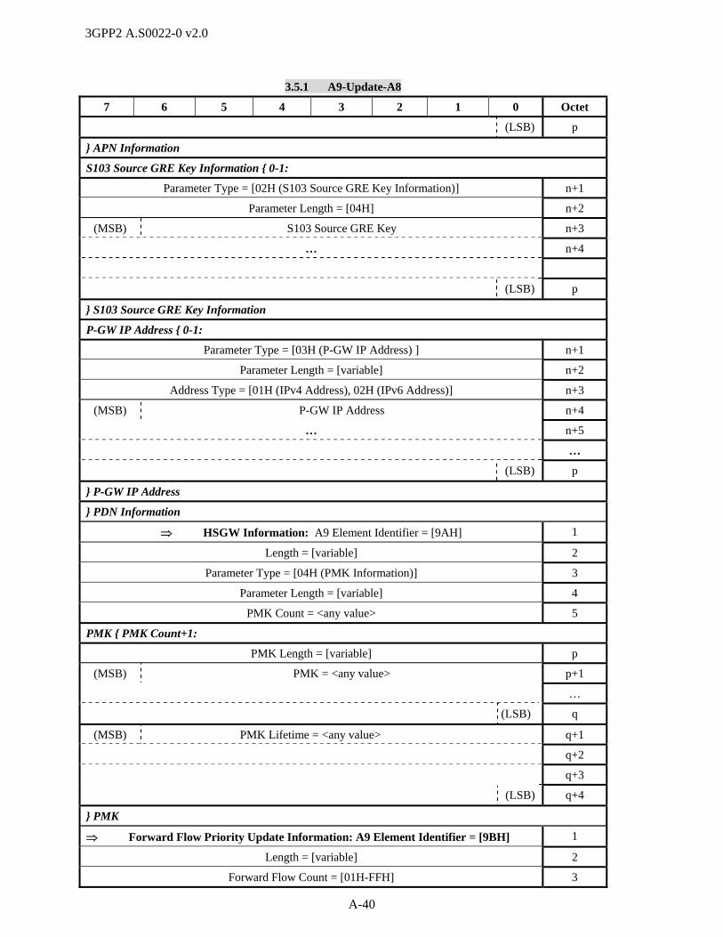
3GPP2 A.S0022-0 v2.0
A-40
3.5.1 A9-Update-A8
7 6 5 4 3 2 1 0 Octet
(LSB) p
} APN Information
S103 Source GRE Key Information { 0-1:
Parameter Type = [02H (S103 Source GRE Key Information)] n+1
Parameter Length = [04H] n+2
(MSB) S103 Source GRE Key n+3
… n+4
(LSB) p
} S103 Source GRE Key Information
P-GW IP Address { 0-1:
Parameter Type = [03H (P-GW IP Address) ] n+1
Parameter Length = [variable] n+2
Address Type = [01H (IPv4 Address), 02H (IPv6 Address)] n+3
(MSB) P-GW IP Address n+4
… n+5
…
(LSB) p
} P-GW IP Address
} PDN Information
HSGW Information: A9 Element Identifier = [9AH] 1
Length = [variable] 2
Parameter Type = [04H (PMK Information)] 3
Parameter Length = [variable] 4
PMK Count = <any value> 5
PMK { PMK Count+1:
PMK Length = [variable] p
(MSB) PMK = <any value> p+1
…
(LSB) q
(MSB) PMK Lifetime = <any value> q+1
q+2
q+3
(LSB) q+4
} PMK
Forward Flow Priority Update Information: A9 Element Identifier = [9BH] 1
Length = [variable] 2
Forward Flow Count = [01H-FFH] 3

3GPP2 A.S0022-0 v2.0
A-41
3.5.1 A9-Update-A8
7 6 5 4 3 2 1 0 Octet
Forward Flow Entry { Forward Flow Count :
Forward Flow ID = [00H – FFH] j
Reserved = [0000] Forward Updated Flow Priority [0H - FH] j+1
} Forward Flow Entry
Reverse Flow Priority Update Information: A9 Element Identifier = [9CH] 1
Length = [variable] 2
Reverse Flow Count = [01H-FFH] 3
Reverse Flow Entry { Reverse Flow Count :
Reverse Flow ID = [00H – FFH] j
Reserved = [0000] Reverse Updated Flow Priority [0H - FH] j+1
} Reverse Flow Entry
… 1
3.5.2 A9-Update-A8 Ack 2
This message is sent from the PCF to the AN to acknowledge a change to the session airlink parameters. 3
This message is also sent from the AN to the PCF to acknowledge the processing of any new or updated 4
session parameters. In HRPD and eHRPD systems, this message is also used to acknowledge the QoS 5
update. In eHRPD systems, this message is also used to acknowledge receipt of PMK information. 6
Information Element Section Reference
Element Direction Type
A9 Message Type [3], [4] AN <-> PCF M
Call Connection Reference [3], [4] AN <-> PCF O R
Correlation ID [3], [4] AN <-> PCF Oa C
Cause [3], [4] AN -> PCF Ob C
Mobile Identity (ATI) [4] AN <-> PCF Oc C
HSGW Information 4.2.4 ePCF -> eAN Od C
7
a. This element shall only be included if it was also included in the A9-Update-A8 message. This 8
element shall be set to the value received in that message. 9
b. The Cause element shall be included when the message is sent by the AN to the PCF to indicate if the 10
updated session parameter(s), Flow Priority update, the QoS update, or the PMK information was 11
accepted by the AN. 12
c. This IE shall not be included in 1x systems. In HRPD and eHRPD systems with SC/MM in the PCF, 13
the AN shall include this IE. 14
d. This IE is included if the ePCF receives HSGW parameters over A11 interface in case of E-UTRAN 15
to eHRPD handoff execution while A8 connection is connected. 16
The following table shows the bitmap layout for the A9-Update-A8 Ack message. 17
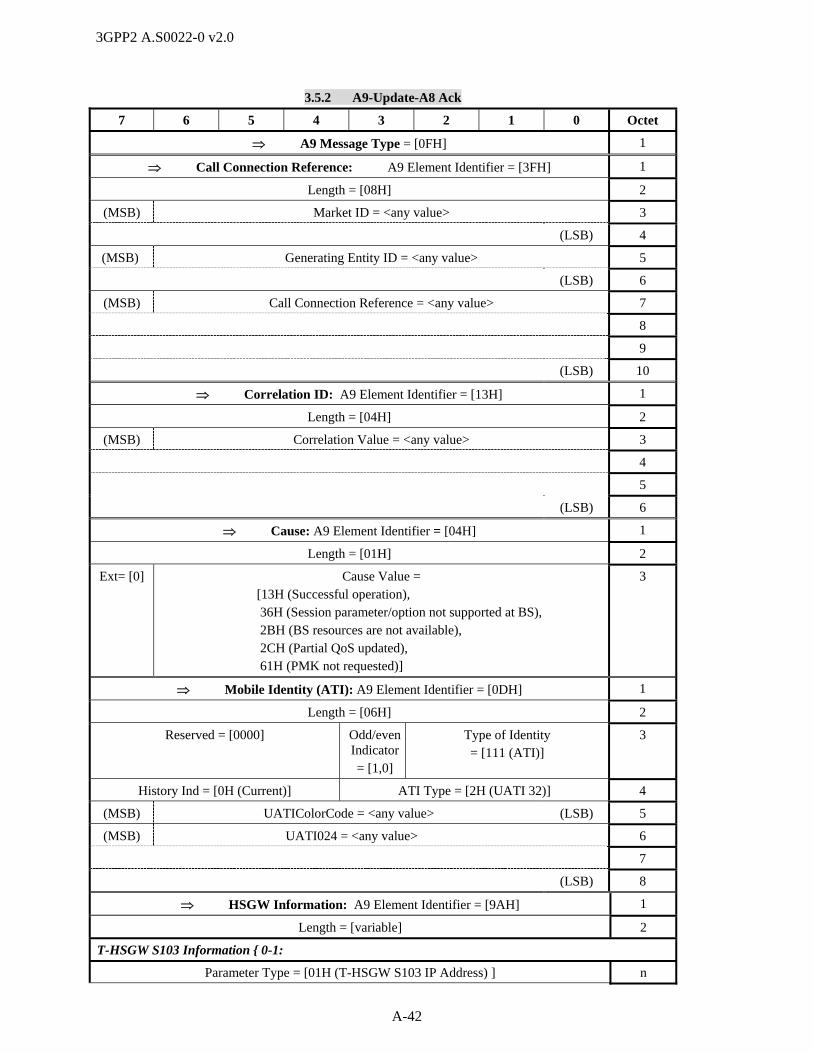
3GPP2 A.S0022-0 v2.0
A-42
3.5.2 A9-Update-A8 Ack
7 6 5 4 3 2 1 0 Octet
A9 Message Type = [0FH] 1
Call Connection Reference: A9 Element Identifier = [3FH] 1
Length = [08H] 2
(MSB) Market ID = <any value> 3
(LSB) 4
(MSB) Generating Entity ID = <any value> 5
(LSB) 6
(MSB) Call Connection Reference = <any value> 7
8
9
(LSB) 10
Correlation ID: A9 Element Identifier = [13H] 1
Length = [04H] 2
(MSB) Correlation Value = <any value> 3
4
5
(LSB) 6
Cause: A9 Element Identifier = [04H] 1
Length = [01H] 2
Ext= [0] Cause Value = [13H (Successful operation), 36H (Session parameter/option not supported at BS), 2BH (BS resources are not available), 2CH (Partial QoS updated), 61H (PMK not requested)]
3
Mobile Identity (ATI): A9 Element Identifier = [0DH] 1
Length = [06H] 2
Reserved = [0000] Odd/even Indicator = [1,0]
Type of Identity = [111 (ATI)]
3
History Ind = [0H (Current)] ATI Type = [2H (UATI 32)] 4
(MSB) UATIColorCode = <any value> (LSB) 5
(MSB) UATI024 = <any value> 6
7
(LSB) 8
HSGW Information: A9 Element Identifier = [9AH] 1
Length = [variable] 2
T-HSGW S103 Information { 0-1:
Parameter Type = [01H (T-HSGW S103 IP Address) ] n

3GPP2 A.S0022-0 v2.0
A-43
3.5.2 A9-Update-A8 Ack
7 6 5 4 3 2 1 0 Octet
Parameter Length = [variable] n+1
Address Type = [01H (IPv4 Address), 02H (IPv6 Address)] n+2
(MSB) T-HSGW S103 IP Address n+3
… …
(LSB) p
Parameter Type = [02H (T-HSGW S103 Key) ] n
Parameter Length = [variable] n+1
(MSB) APN n+2
… …
(LSB) p
(MSB) T-HSGW S103 Key p+1
… p+2
p+3
(LSB) p+4
} HSGW S103 Information
HSGW H1 Information { 0-1:
Parameter Type = [03H (HSGW H1 Address Information) ] n
Parameter Length = [05H] n+1
Address Type = [01H (IPv4 Address)] n+2
(MSB) HSGW H1 IP Address n+3
… n+4
n+5
(LSB) n+6
} HSGW H1 Information
… 1
4.1.2 Information Element Identifiers 2
The following table contains a list of all information elements that make up the messages defined in 3
section 3.0. The table is sorted by the Information Element Identifier (IEI) coding which distinguishes one 4
information element from another. The table also includes a reference to the section where the element 5
coding can be found. 6
A listing of information elements, sorted by name, is included in Table 4.1.4-1, which also specifies the 7
messages in which each information element is used. 8
Table 4.1.2-1 A9 Information Element Identifiers Sorted by Identifier Value 9
Element Name Identifier Reference
CON_REF 01H [3], [4]
User Zone ID 02H [3], [4]
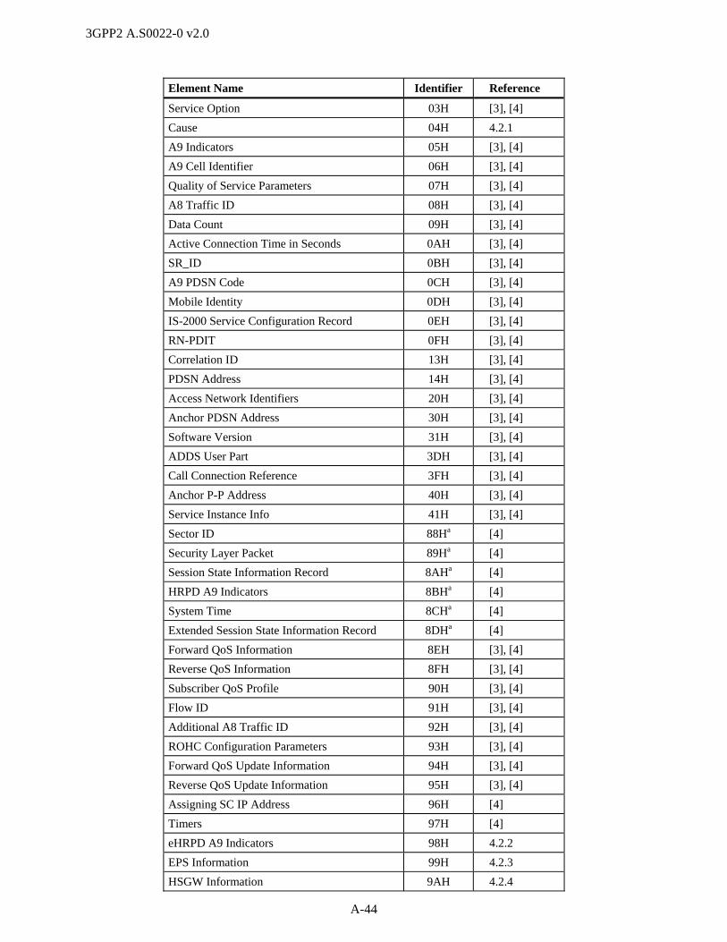
3GPP2 A.S0022-0 v2.0
A-44
Element Name Identifier Reference
Service Option 03H [3], [4]
Cause 04H 4.2.1
A9 Indicators 05H [3], [4]
A9 Cell Identifier 06H [3], [4]
Quality of Service Parameters 07H [3], [4]
A8 Traffic ID 08H [3], [4]
Data Count 09H [3], [4]
Active Connection Time in Seconds 0AH [3], [4]
SR_ID 0BH [3], [4]
A9 PDSN Code 0CH [3], [4]
Mobile Identity 0DH [3], [4]
IS-2000 Service Configuration Record 0EH [3], [4]
RN-PDIT 0FH [3], [4]
Correlation ID 13H [3], [4]
PDSN Address 14H [3], [4]
Access Network Identifiers 20H [3], [4]
Anchor PDSN Address 30H [3], [4]
Software Version 31H [3], [4]
ADDS User Part 3DH [3], [4]
Call Connection Reference 3FH [3], [4]
Anchor P-P Address 40H [3], [4]
Service Instance Info 41H [3], [4]
Sector ID 88Ha [4]
Security Layer Packet 89Ha [4]
Session State Information Record 8AHa [4]
HRPD A9 Indicators 8BHa [4]
System Time 8CHa [4]
Extended Session State Information Record 8DHa [4]
Forward QoS Information 8EH [3], [4]
Reverse QoS Information 8FH [3], [4]
Subscriber QoS Profile 90H [3], [4]
Flow ID 91H [3], [4]
Additional A8 Traffic ID 92H [3], [4]
ROHC Configuration Parameters 93H [3], [4]
Forward QoS Update Information 94H [3], [4]
Reverse QoS Update Information 95H [3], [4]
Assigning SC IP Address 96H [4]
Timers 97H [4]
eHRPD A9 Indicators 98H 4.2.2
EPS Information 99H 4.2.3
HSGW Information 9AH 4.2.4

3GPP2 A.S0022-0 v2.0
A-45
Element Name Identifier Reference
Forward Flow Priority Update Information 9BH [3], [4]
Reverse Flow Priority Update Information 9CH [3], [4]
1
a. This IE is also used in HRPD Systems on the A9 interface. 2
… 3
4.1.4 Cross Reference of Information Elements With Messages 4
The following table provides a cross reference between the elements defined in this specification and the 5
messages defined herein. 6
Table 4.1.4-1 Cross Reference of Information Elements with Messages
Information Element Reference IEI Used in These Messages
A8 Traffic ID [3], [4] 08H A9-Setup-A8 3.1.1
A9-AL Connected 3.3.1
A9-AL Disconnected 3.3.3
A9-Connect-A8 3.1.2
A9-Disconnect-A8 3.2.3
A9-Release-A8 3.2.1
A9 Cell Identifier [3], [4] 06H A9-Setup-A8 3.1.1
A9 Indicators [3], [4] 05H A9-Connect-A8 3.1.2
A9-Setup-A8 3.1.1
A9-Short Data Delivery 3.6.1
A9-Update-A8 3.5.1
A9 Message Type [3], [4] None A9-Setup-A8 3.1.1
A9-AL Connected 3.3.1
A9-AL Connected Ack 3.3.2
A9-AL Disconnected 3.3.3
A9-AL Disconnected Ack 3.3.4
A9-BS Service Request 3.1.3
A9-BS Service Response 3.1.4
A9-Connect-A8 3.1.2
A9-Disconnect-A8 3.2.3
A9-Release-A8 3.2.1
A9-Release-A8 Complete 3.2.2
A9-Short Data Delivery 3.6.1
A9-Short Data Ack 3.6.2
A9-Update-A8 3.5.1
A9-Update-A8 Ack 3.5.2
A9-Version Info 3.4.1

3GPP2 A.S0022-0 v2.0
A-46
Table 4.1.4-1 Cross Reference of Information Elements with Messages
Information Element Reference IEI Used in These Messages
A9-Version Info Ack 3.4.2
A9 PDSN Code [3], [4] 0CH A9-Disconnect-A8 3.2.3
A9-Release-A8 Complete 3.2.2
Access Network Identifier [3], [4] 20H A9-Setup-A8 3.1.1
A9-AL Connected 3.3.1
Active Connection Time in Seconds [3], [4] 0AH A9-Release-A8 3.2.1
Additional A8 Traffic ID [3], [4] 92H A9-Setup-A8 3.1.1
A9-Connect-A8 3.1.2
A9-Release-A8 3.2.1
ADDS User Part [3], [4] 3DH A9-Short Data Delivery 3.6.1
Anchor P-P Address [3], [4] 40H A9-Setup-A8 3.1.1
A9-Connect-A8 3.1.2
A9-AL Connected Ack 3.3.2
A9-Update-A8 3.5.1
Anchor PDSN Address [3], [4] 30H A9-Setup-A8 3.1.1
A9-Connect-A8 3.1.2
A9-AL Connected Ack 3.3.2
A9-Update-A8 3.5.1
Assigning SC IP Address [4] 96H A9-Setup-A8 3.1.1
A9-Connect-A8 3.1.2
Call Connection Reference [3], [4] 3FH A9-AL Connected 3.3.1
A9-AL Connected Ack 3.3.2
A9-AL Disconnected 3.3.3
A9-AL Disconnected Ack 3.3.4
A9-Connect-A8 3.1.2
A9-Disconnect-A8 3.2.3
A9-Setup-A8 3.1.1
A9-Release-A8 3.2.1
A9-Release-A8 Complete 3.2.2
A9-Update-A8 3.5.1
A9-Update-A8 Ack 3.5.2
Cause 4.2.1 04H A9-Connect-A8 3.1.2
A9-Disconnect-A8 3.2.3
A9-Release-A8 3.2.1
A9-Release-A8 Complete 3.2.2
A9-BS Service Response 3.1.4
A9-Short Data Ack 3.6.2
A9-Update-A8 3.5.1
A9-Update-A8 Ack 3.5.2

3GPP2 A.S0022-0 v2.0
A-47
Table 4.1.4-1 Cross Reference of Information Elements with Messages
Information Element Reference IEI Used in These Messages
A9-Version Info 3.4.1
CON_REF [3], [4] 01H A9-Setup-A8 3.1.1
A9-Connect-A8 3.1.2
A9-Disconnect-A8 3.2.3
A9-Release-A8 3.2.1
Correlation ID [3], [4] 13H A9-AL Disconnected Ack 3.3.4
A9-Short Data Delivery 3.6.1
A9-Short Data Ack 3.6.2
A9-Setup-A8 3.1.1
A9-Connect-A8 3.1.2
A9-Disconnect-A8 3.2.3
A9-Release-A8 3.2.1
A9-Release-A8 Complete 3.2.2
Data Count [3], [4] 09H A9-BS Service Request 3.1.3
A9-Short Data Delivery 3.6.1
eHRPD A9 Indicators 4.2.2 98H A9-Setup-A8 3.1.1
A9-Release-A8 3.2.1
A9-Update-A8 3.5.1
EPS Information 4.2.3 99H A9-Setup-A8 3.1.1
A9-Update-A8 3.5.1
Extended SSIR [4] 8DH A9-Connect-A8 3.1.2
A9-Release-A8 3.2.1
A9-Release-A8 Complete 3.2.2
A9-Short Data Delivery 3.6.1
Flow ID [3], [4] 91H A9-Short Data Delivery 3.6.1
Forward Flow Priority Update Information
[3], [4] 9BH A9-Update-A8 3.5.1
Forward QoS Information [3], [4] 8EH A9-Setup-A8 3.1.1
A9-Release-A8 3.2.1
A9-Update-A8 3.5.1
Forward QoS Update Information [3], [4] 94H A9-Update-A8 3.5.1
HRPD A9 Indicators [4] 8BH A9-Setup-A8 3.1.1
A9-Release-A8 Complete 3.2.2
HSGW Information 4.2.4 9AH A9-Connect-A8 3.1.2
A9-Update-A8 3.5.1
A9-Update-A8 Ack 3.5.2
IS-2000 Service Configuration Record
[3], [4] 0EH A9-Setup-A8 3.1.1
A9-AL Connected 3.3.1
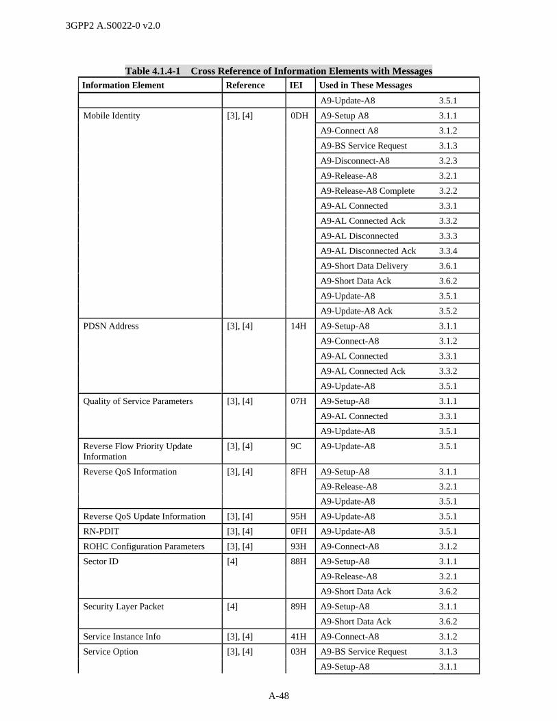
3GPP2 A.S0022-0 v2.0
A-48
Table 4.1.4-1 Cross Reference of Information Elements with Messages
Information Element Reference IEI Used in These Messages
A9-Update-A8 3.5.1
Mobile Identity [3], [4] 0DH A9-Setup A8 3.1.1
A9-Connect A8 3.1.2
A9-BS Service Request 3.1.3
A9-Disconnect-A8 3.2.3
A9-Release-A8 3.2.1
A9-Release-A8 Complete 3.2.2
A9-AL Connected 3.3.1
A9-AL Connected Ack 3.3.2
A9-AL Disconnected 3.3.3
A9-AL Disconnected Ack 3.3.4
A9-Short Data Delivery 3.6.1
A9-Short Data Ack 3.6.2
A9-Update-A8 3.5.1
A9-Update-A8 Ack 3.5.2
PDSN Address [3], [4] 14H A9-Setup-A8 3.1.1
A9-Connect-A8 3.1.2
A9-AL Connected 3.3.1
A9-AL Connected Ack 3.3.2
A9-Update-A8 3.5.1
Quality of Service Parameters [3], [4] 07H A9-Setup-A8 3.1.1
A9-AL Connected 3.3.1
A9-Update-A8 3.5.1
Reverse Flow Priority Update Information
[3], [4] 9C A9-Update-A8 3.5.1
Reverse QoS Information [3], [4] 8FH A9-Setup-A8 3.1.1
A9-Release-A8 3.2.1
A9-Update-A8 3.5.1
Reverse QoS Update Information [3], [4] 95H A9-Update-A8 3.5.1
RN-PDIT [3], [4] 0FH A9-Update-A8 3.5.1
ROHC Configuration Parameters [3], [4] 93H A9-Connect-A8 3.1.2
Sector ID [4] 88H A9-Setup-A8 3.1.1
A9-Release-A8 3.2.1
A9-Short Data Ack 3.6.2
Security Layer Packet [4] 89H A9-Setup-A8 3.1.1
A9-Short Data Ack 3.6.2
Service Instance Info [3], [4] 41H A9-Connect-A8 3.1.2
Service Option [3], [4] 03H A9-BS Service Request 3.1.3
A9-Setup-A8 3.1.1

3GPP2 A.S0022-0 v2.0
A-49
Table 4.1.4-1 Cross Reference of Information Elements with Messages
Information Element Reference IEI Used in These Messages
A9-AL Connected 3.3.1
A9-Update-A8 3.5.1
Session State Information Record [4] 8AH A9-Connect-A8 3.1.2
A9-Release-A8 3.2.1
A9-Release-A8 Complete 3.2.2
A9-Short Data Delivery 3.6.1
A9-Short Data Ack 3.6.2
Software Version [3], [4] 31H A9-Version Info 3.4.1
A9-Version Info Ack 3.4.2
SR_ID [3], [4] 0BH A9-Setup-A8 3.1.1
A9-Connect-A8 3.1.2
A9-Disconnect-A8 3.2.3
A9-Release-A8 3.2.1
A9-Release-A8 Complete 3.2.2
A9-BS Service Request 3.1.3
A9-BS Service Response 3.1.4
A9-Short Data Delivery 3.6.1
A9-Update-A8 3.5.1
A9-AL Disconnected 3.3.3
Subscriber QoS Profile [3], [4] 90H A9-Connect-A8 3.1.2
A9-Update-A8 3.5.1
System Time [4] 8CH A9-Setup-A8 3.1.1
A9-Short Data Ack 3.6.2
Timers [4] 97H A9-Setup-A8 3.1.1
A9-AL Disconnected 3.3.3
User Zone ID [3], [4] 02H A9-Setup-A8 3.1.1
A9-AL Connected 3.3.1
A9-Update-A8 3.5.1
… 1
4.2.1 Cause 2
This element is used to indicate the reason for occurrence of a particular event and is coded as shown 3
below. 4
4.2.1 Cause
7 6 5 4 3 2 1 0 Octet
A9 Element Identifier 1
Length 2
0/1 Cause Value 3
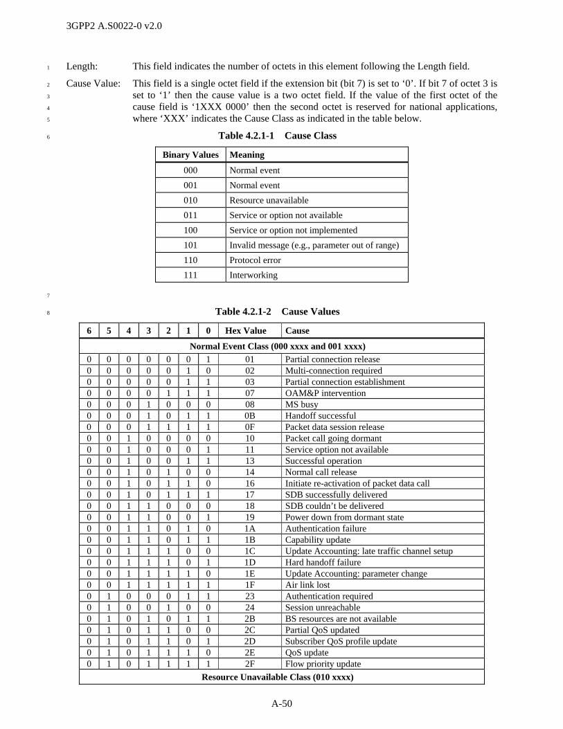
3GPP2 A.S0022-0 v2.0
A-50
Length: This field indicates the number of octets in this element following the Length field. 1
Cause Value: This field is a single octet field if the extension bit (bit 7) is set to ‘0’. If bit 7 of octet 3 is 2
set to ‘1’ then the cause value is a two octet field. If the value of the first octet of the 3
cause field is ‘1XXX 0000’ then the second octet is reserved for national applications, 4
where ‘XXX’ indicates the Cause Class as indicated in the table below. 5
Table 4.2.1-1 Cause Class 6
Binary Values Meaning
000 Normal event
001 Normal event
010 Resource unavailable
011 Service or option not available
100 Service or option not implemented
101 Invalid message (e.g., parameter out of range)
110 Protocol error
111 Interworking
7
Table 4.2.1-2 Cause Values 8
6 5 4 3 2 1 0 Hex Value Cause
Normal Event Class (000 xxxx and 001 xxxx)
0 0 0 0 0 0 1 01 Partial connection release 0 0 0 0 0 1 0 02 Multi-connection required 0 0 0 0 0 1 1 03 Partial connection establishment 0 0 0 0 1 1 1 07 OAM&P intervention 0 0 0 1 0 0 0 08 MS busy 0 0 0 1 0 1 1 0B Handoff successful 0 0 0 1 1 1 1 0F Packet data session release 0 0 1 0 0 0 0 10 Packet call going dormant 0 0 1 0 0 0 1 11 Service option not available 0 0 1 0 0 1 1 13 Successful operation 0 0 1 0 1 0 0 14 Normal call release 0 0 1 0 1 1 0 16 Initiate re-activation of packet data call 0 0 1 0 1 1 1 17 SDB successfully delivered 0 0 1 1 0 0 0 18 SDB couldn’t be delivered 0 0 1 1 0 0 1 19 Power down from dormant state 0 0 1 1 0 1 0 1A Authentication failure 0 0 1 1 0 1 1 1B Capability update 0 0 1 1 1 0 0 1C Update Accounting: late traffic channel setup 0 0 1 1 1 0 1 1D Hard handoff failure 0 0 1 1 1 1 0 1E Update Accounting: parameter change 0 0 1 1 1 1 1 1F Air link lost 0 1 0 0 0 1 1 23 Authentication required 0 1 0 0 1 0 0 24 Session unreachable 0 1 0 1 0 1 1 2B BS resources are not available 0 1 0 1 1 0 0 2C Partial QoS updated 0 1 0 1 1 0 1 2D Subscriber QoS profile update 0 1 0 1 1 1 0 2E QoS update 0 1 0 1 1 1 1 2F Flow priority update
Resource Unavailable Class (010 xxxx)

3GPP2 A.S0022-0 v2.0
A-51
6 5 4 3 2 1 0 Hex Value Cause
0 1 0 0 0 0 0 20 Equipment failure Service or Option Not Available Class (011 xxxx)
0 1 1 0 0 1 0 32 PCF resources are not available 0 1 1 0 1 1 0 36 Session parameter/option not supported at BS
Service or Option Not Implemented Class (100 xxxx) Invalid Message Class (101 xxxx)
Protocol Error (110 xxxx) 1 1 0 0 0 0 0 60 State mismatch 1 1 0 0 0 0 1 61 PMK not requested
Interworking (111 xxxx) 1 1 1 1 0 0 1 79 PDSN resources are not available 1 1 1 1 0 1 0 7A Data ready to send 1 1 1 1 0 1 1 7B Session parameter update
All other values Reserved for future use.
1
4.2.2 eHRPD A9 Indicators 2
This IE is used to provide indications related to eHRPD operation. 3
4.2.2 eHRPD A9 Indicators
7 6 5 4 3 2 1 0 Octet
A9 Element Identifier = [98H] 1
Length 2
Reserved PMK Handoff Execution
Tunnel Mode
3
Length This field contains the number of octets in this IE following this 4
field as a binary number. 5
Tunnel Mode The field indicates whether or not the eAT is operating on the 6
eHRPD radio, as follows: 7
The Tunnel Mode indication is set to 0 to indicate that the 8
eAT is operating on the eHRPD radio (e.g., the eAT is 9
communicating directly via eHRPD). 10
The Tunnel Mode indication is set to 1 to indicate that the 11
eAT is not operating on the eHRPD radio (e.g., the eAT is 12
communicating via a tunnel from another access 13
technology). 14
When the eHRPD system supports optimized mobility between 15
eHRPD and E-UTRAN, the eAN includes the Tunnel Mode 16
indication in the A9-Setup-A8 messages sent to the ePCF for an 17
evolved mode session, and sets the value of the Tunnel Mode 18
indication value appropriately. The eAN may not include the 19
Tunnel Mode indication in any A9-Setup-A8 messages sent to 20
the ePCF for an evolved mode session if the eHRPD system does 21
not support optimized mobility between eHRPD and E-UTRAN. 22
The ePCF shall treat the absence of the Tunnel Mode indication 23
from an A9-Setup-A8 message for an evolved mode session the 24
same as Tunnel Mode indication of ‘0’. 25
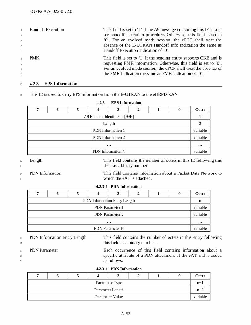
3GPP2 A.S0022-0 v2.0
A-52
Handoff Execution This field is set to ‘1’ if the A9 message containing this IE is sent 1
for handoff execution procedure. Otherwise, this field is set to 2
‘0’. For an evolved mode session, the ePCF shall treat the 3
absence of the E-UTRAN Handoff Info indication the same as 4
Handoff Execution indication of ‘0’. 5
PMK This field is set to ‘1’ if the sending entity supports GKE and is 6
requesting PMK information. Otherwise, this field is set to ‘0’. 7
For an evolved mode session, the ePCF shall treat the absence of 8
the PMK indication the same as PMK indication of ‘0’. 9
4.2.3 EPS Information 10
This IE is used to carry EPS information from the E-UTRAN to the eHRPD RAN. 11
4.2.3 EPS Information
7 6 5 4 3 2 1 0 Octet
A9 Element Identifier = [99H] 1
Length 2
PDN Information 1 variable
PDN Information 2 variable
… …
PDN Information N variable
Length This field contains the number of octets in this IE following this 12
field as a binary number. 13
PDN Information This field contains information about a Packet Data Network to 14
which the eAT is attached. 15
4.2.3-1 PDN Information
7 6 5 4 3 2 1 0 Octet
PDN Information Entry Length n
PDN Parameter 1 variable
PDN Parameter 2 variable
… …
PDN Parameter N variable
PDN Information Entry Length This field contains the number of octets in this entry following 16
this field as a binary number. 17
PDN Parameter Each occurrence of this field contains information about a 18
specific attribute of a PDN attachment of the eAT and is coded 19
as follows. 20
4.2.3-1 PDN Information
7 6 5 4 3 2 1 0 Octet
Parameter Type n+1
Parameter Length n+2
Parameter Value variable

3GPP2 A.S0022-0 v2.0
A-53
Parameter Type This field indicates the type of parameter included in the 1
Parameter Value field. The supported types are listed as follows. 2
PDN Parameter Type Description
01H APN Information 02H S103 Source GRE Key Information 03H P-GW IP Address
All other values Reserved
3
Parameter Length This field contains the number of octets in this entry following 4
this field as a binary number. 5
Parameter Value This field contains the specific PDN attribute and is coded as 6
follows. 7
When the Parameter Type is set to ‘01H (APN Information)’, the Parameter Value field is coded as 8
follows. 9
7 6 5 4 3 2 1 0 Octet
APN n+3
… …
(LSB) p
APN This field contains the fully qualified domain name of the access 10
provider as an ASCII character string. 11
When the Parameter Type is set to ‘02H (S103 Source GRE Key Information)’, the Parameter Value field 12
is coded as follows. 13
7 6 5 4 3 2 1 0 Octet
S103 Source GRE Key n+4
n+4
n+5
(LSB) n+6
S103 Source GRE Key This is a four octet field. This field contains the same value that 14
is used in the Key field in the GRE header on the associated 15
connection between P-GW and HSGW or S-GW. 16
When the Parameter Type is set to ‘03H (P-GW IP Address)’, the Parameter Value field is coded as 17
follows. 18
7 6 5 4 3 2 1 0 Octet
Address Type
(MSB) P-GW IP Address n+3
… …
(LSB) p
Address Type This field indicates the type and format of the IP address. This 19
field is set to ‘01H’ for IPv4 IP address. This field is set to ‘02H’ 20
for IPv6 IP address. 21

3GPP2 A.S0022-0 v2.0
A-54
P-GW IP Address This field identifies the IP address of the P-GW that terminates 1
the GRE connection between P-GW and HSGW or S-GW. When 2
the Address Type field is set to ‘01H’, this field is coded with 4 3
octet length to include IPv4 address. When the Address Type 4
field is set to ‘02H’, this field is coded with 16 octet length to 5
include IPv6 address. 6
4.2.4 HSGW Information 7
This IE is used to carry HSGW information from the E-UTRAN to the eHRPD RAN and between ePCF 8
and eAN. 9
4.2.4 HSGW Information
7 6 5 4 3 2 1 0 Octet
A9 Element Identifier = [9AH] 1
Length 2
HSGW Parameter 1 variable
HSGW Parameter 2 variable
… …
HSGW Parameter N variable
Length This field contains the number of octets in this IE following this 10
field as a binary number. 11
HSGW Parameter This field contains timer information and is coded as follows. 12
4.2.4-1 HSGW Parameter
7 6 5 4 3 2 1 0 Octet
Parameter Type n
Parameter Length n+1
Parameter Value variable
Parameter Type This field indicates the type of parameter included in the 13
Parameter Value field. The supported types are listed as follows. 14
HSGW Parameter Type Description
01H T-HSGW S103 IP Address 02H T-HSGW S103 Key 03H HSGW H1 Address Information 04H PMK Information
All other values Reserved
15
Parameter Length This field contains the number of octets in this entry following 16
this field as a binary number. 17
Parameter Value This field contains HSGW information and is coded as follows. 18
19

3GPP2 A.S0022-0 v2.0
A-55
When the Parameter Type is set to ‘01H (T-HSGW S103 IP Address)’, the Parameter Value field is coded 1
as follows. 2
7 6 5 4 3 2 1 0 Octet
Address Type n+2
(MSB) T-HSGW S103 IP Address n+3
… …
(LSB) p
Address Type This field indicates the type and format of the IP address. This 3
field is set to ‘01H’ for IPv4 IP address. This field is set to ‘02H’ 4
for IPv6 IP address. 5
HSGW S103 IP Address This field identifies the S103 IP address of the HSGW. When the 6
Address Type field is set to ‘01H’, this field is coded with 4 octet 7
length to include IPv4 address. When the Address Type field is 8
set to ‘02H’, this field is coded with 16 octet length to include 9
IPv6 address. 10
When the Parameter Type is set to ‘02H (T-HSGW S103 Key)’, the Parameter Value field is coded as 11
follows. 12
7 6 5 4 3 2 1 0 Octet
(MSB) APN n+2
… …
(LSB) p
(MSB) T-HSGW S103 Key p+1
p+2
p+3
(LSB) p+4
APN This field contains the fully qualified domain name of the access 13
provider as an ASCII character string. 14
HSGW S103 Key This is a four octet field. This field contains the same value that 15
is used in the Key field in the GRE header on the connection 16
from the S-GW to the T-HSGW associated with the specified 17
APN (refer to TS 29.276 [2]). 18
19
When the Parameter Type is set to ‘03H (HSGW H1 Address Information)’, the Parameter Value field is 20
coded as follows. 21
7 6 5 4 3 2 1 0 Octet
Address Type n+2
(MSB) HSGW H1 IP Address n+3
… …
(LSB) p
Address Type This field indicates the type and format of the IP address. This 22
field is set to ‘01H’ for IPv4 address. 23

3GPP2 A.S0022-0 v2.0
A-56
HSGW H1 IP Address When Address Type field is set to ‘01H’, this field is coded with 1
4 octet length to include IPv4 address. 2
When the Parameter Type is set to ‘04H (PMK Information)’, the Parameter Value field is coded as 3
follows. 4
5
0 1 2 3 4 5 6 7 Octet
PMK Count n+2
PMK n Length p
(MSB) PMK n p+1
… …
(LSB) q
(MSB) PMK n Lifetime q+1
q+2
q+3
(LSB) q+4
6
PMK Count This field shall be set to the number of occurrences of the PMK 7
field in this parameter record. 8
PMK Length This field indicates the length of a PMK in octets. 9
PMK This field contains a PairwiseMasterKey. 10
PMK Lifetime This field indicates the length of time (in seconds) for which the 11
included PMKs are valid as an unsigned 32-bit binary number. 12
13
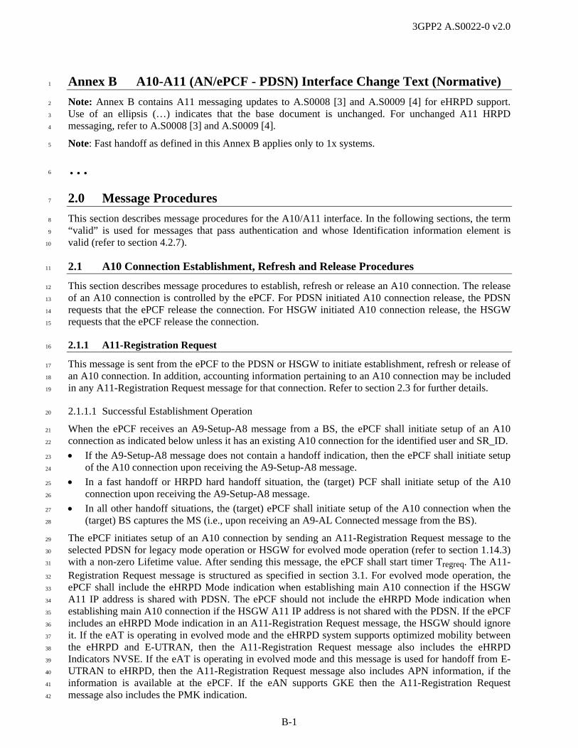
3GPP2 A.S0022-0 v2.0
B-1
Annex B A10-A11 (AN/ePCF - PDSN) Interface Change Text (Normative) 1
Note: Annex B contains A11 messaging updates to A.S0008 [3] and A.S0009 [4] for eHRPD support. 2
Use of an ellipsis (…) indicates that the base document is unchanged. For unchanged A11 HRPD 3
messaging, refer to A.S0008 [3] and A.S0009 [4]. 4
Note: Fast handoff as defined in this Annex B applies only to 1x systems. 5
… 6
2.0 Message Procedures 7
This section describes message procedures for the A10/A11 interface. In the following sections, the term 8
“valid” is used for messages that pass authentication and whose Identification information element is 9
valid (refer to section 4.2.7). 10
2.1 A10 Connection Establishment, Refresh and Release Procedures 11
This section describes message procedures to establish, refresh or release an A10 connection. The release 12
of an A10 connection is controlled by the ePCF. For PDSN initiated A10 connection release, the PDSN 13
requests that the ePCF release the connection. For HSGW initiated A10 connection release, the HSGW 14
requests that the ePCF release the connection. 15
2.1.1 A11-Registration Request 16
This message is sent from the ePCF to the PDSN or HSGW to initiate establishment, refresh or release of 17
an A10 connection. In addition, accounting information pertaining to an A10 connection may be included 18
in any A11-Registration Request message for that connection. Refer to section 2.3 for further details. 19
2.1.1.1 Successful Establishment Operation 20
When the ePCF receives an A9-Setup-A8 message from a BS, the ePCF shall initiate setup of an A10 21
connection as indicated below unless it has an existing A10 connection for the identified user and SR_ID. 22
If the A9-Setup-A8 message does not contain a handoff indication, then the ePCF shall initiate setup 23
of the A10 connection upon receiving the A9-Setup-A8 message. 24
In a fast handoff or HRPD hard handoff situation, the (target) PCF shall initiate setup of the A10 25
connection upon receiving the A9-Setup-A8 message. 26
In all other handoff situations, the (target) ePCF shall initiate setup of the A10 connection when the 27
(target) BS captures the MS (i.e., upon receiving an A9-AL Connected message from the BS). 28
The ePCF initiates setup of an A10 connection by sending an A11-Registration Request message to the 29
selected PDSN for legacy mode operation or HSGW for evolved mode operation (refer to section 1.14.3) 30
with a non-zero Lifetime value. After sending this message, the ePCF shall start timer Tregreq. The A11-31
Registration Request message is structured as specified in section 3.1. For evolved mode operation, the 32
ePCF shall include the eHRPD Mode indication when establishing main A10 connection if the HSGW 33
A11 IP address is shared with PDSN. The ePCF should not include the eHRPD Mode indication when 34
establishing main A10 connection if the HSGW A11 IP address is not shared with the PDSN. If the ePCF 35
includes an eHRPD Mode indication in an A11-Registration Request message, the HSGW should ignore 36
it. If the eAT is operating in evolved mode and the eHRPD system supports optimized mobility between 37
the eHRPD and E-UTRAN, then the A11-Registration Request message also includes the eHRPD 38
Indicators NVSE. If the eAT is operating in evolved mode and this message is used for handoff from E-39
UTRAN to eHRPD, then the A11-Registration Request message also includes APN information, if the 40
information is available at the ePCF. If the eAN supports GKE then the A11-Registration Request 41
message also includes the PMK indication. 42
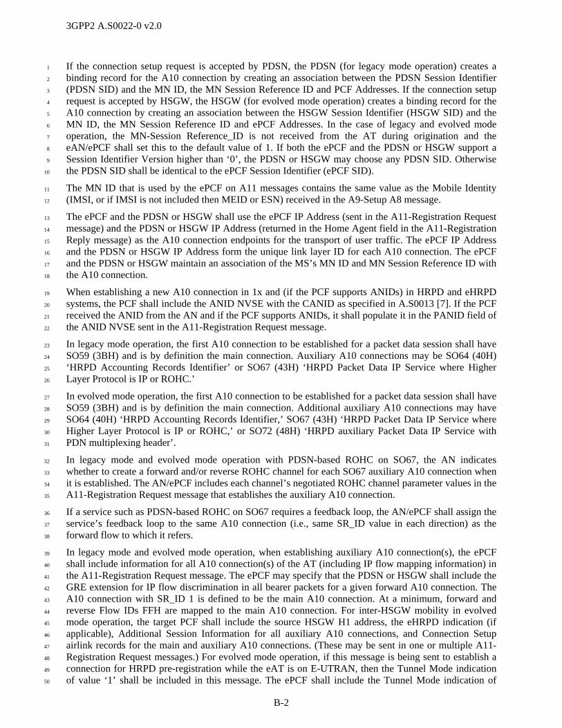
3GPP2 A.S0022-0 v2.0
B-2
If the connection setup request is accepted by PDSN, the PDSN (for legacy mode operation) creates a 1
binding record for the A10 connection by creating an association between the PDSN Session Identifier 2
(PDSN SID) and the MN ID, the MN Session Reference ID and PCF Addresses. If the connection setup 3
request is accepted by HSGW, the HSGW (for evolved mode operation) creates a binding record for the 4
A10 connection by creating an association between the HSGW Session Identifier (HSGW SID) and the 5
MN ID, the MN Session Reference ID and ePCF Addresses. In the case of legacy and evolved mode 6
operation, the MN-Session Reference_ID is not received from the AT during origination and the 7
eAN/ePCF shall set this to the default value of 1. If both the ePCF and the PDSN or HSGW support a 8
Session Identifier Version higher than ‘0’, the PDSN or HSGW may choose any PDSN SID. Otherwise 9
the PDSN SID shall be identical to the ePCF Session Identifier (ePCF SID). 10
The MN ID that is used by the ePCF on A11 messages contains the same value as the Mobile Identity 11
(IMSI, or if IMSI is not included then MEID or ESN) received in the A9-Setup A8 message. 12
The ePCF and the PDSN or HSGW shall use the ePCF IP Address (sent in the A11-Registration Request 13
message) and the PDSN or HSGW IP Address (returned in the Home Agent field in the A11-Registration 14
Reply message) as the A10 connection endpoints for the transport of user traffic. The ePCF IP Address 15
and the PDSN or HSGW IP Address form the unique link layer ID for each A10 connection. The ePCF 16
and the PDSN or HSGW maintain an association of the MS’s MN ID and MN Session Reference ID with 17
the A10 connection. 18
When establishing a new A10 connection in 1x and (if the PCF supports ANIDs) in HRPD and eHRPD 19
systems, the PCF shall include the ANID NVSE with the CANID as specified in A.S0013 [7]. If the PCF 20
received the ANID from the AN and if the PCF supports ANIDs, it shall populate it in the PANID field of 21
the ANID NVSE sent in the A11-Registration Request message. 22
In legacy mode operation, the first A10 connection to be established for a packet data session shall have 23
SO59 (3BH) and is by definition the main connection. Auxiliary A10 connections may be SO64 (40H) 24
‘HRPD Accounting Records Identifier’ or SO67 (43H) ‘HRPD Packet Data IP Service where Higher 25
Layer Protocol is IP or ROHC.’ 26
In evolved mode operation, the first A10 connection to be established for a packet data session shall have 27
SO59 (3BH) and is by definition the main connection. Additional auxiliary A10 connections may have 28
SO64 (40H) ‘HRPD Accounting Records Identifier,’ SO67 (43H) ‘HRPD Packet Data IP Service where 29
Higher Layer Protocol is IP or ROHC,’ or SO72 (48H) ‘HRPD auxiliary Packet Data IP Service with 30
PDN multiplexing header’. 31
In legacy mode and evolved mode operation with PDSN-based ROHC on SO67, the AN indicates 32
whether to create a forward and/or reverse ROHC channel for each SO67 auxiliary A10 connection when 33
it is established. The AN/ePCF includes each channel’s negotiated ROHC channel parameter values in the 34
A11-Registration Request message that establishes the auxiliary A10 connection. 35
If a service such as PDSN-based ROHC on SO67 requires a feedback loop, the AN/ePCF shall assign the 36
service’s feedback loop to the same A10 connection (i.e., same SR_ID value in each direction) as the 37
forward flow to which it refers. 38
In legacy mode and evolved mode operation, when establishing auxiliary A10 connection(s), the ePCF 39
shall include information for all A10 connection(s) of the AT (including IP flow mapping information) in 40
the A11-Registration Request message. The ePCF may specify that the PDSN or HSGW shall include the 41
GRE extension for IP flow discrimination in all bearer packets for a given forward A10 connection. The 42
A10 connection with SR_ID 1 is defined to be the main A10 connection. At a minimum, forward and 43
reverse Flow IDs FFH are mapped to the main A10 connection. For inter-HSGW mobility in evolved 44
mode operation, the target PCF shall include the source HSGW H1 address, the eHRPD indication (if 45
applicable), Additional Session Information for all auxiliary A10 connections, and Connection Setup 46
airlink records for the main and auxiliary A10 connections. (These may be sent in one or multiple A11-47
Registration Request messages.) For evolved mode operation, if this message is being sent to establish a 48
connection for HRPD pre-registration while the eAT is on E-UTRAN, then the Tunnel Mode indication 49
of value ‘1’ shall be included in this message. The ePCF shall include the Tunnel Mode indication of 50

3GPP2 A.S0022-0 v2.0
B-3
value ‘1’ in all A11-Registration Request messages sent to the HSGW for the A10 session while the eAT 1
is connected to the eHRPD system via the S101 interface. When the Tunnel Mode indication of value ‘1’ 2
is present, A11-Registration Request messages sent for the A10 session do not result in PMIP binding 3
update from HSGW to P-GW. 4
For handoff from E-UTRAN to eHRPD, the target PCF shall include the user’s APN information, if 5
available at the ePCF. For optimized handoff from eHRPD to E-UTRAN, the source ePCF shall include 6
the E-UTRAN Handoff Information Request Indicator to request the user’s APN information from the 7
HSGW. 8
In HRPD systems, if the PCF receives an ‘Emergency Services’ indication in an A9-Setup-A8 or an A9-9
Update-A8 message, the PCF sets the ‘Emergency Services’ indicator to ‘1’ in the A11-Registration 10
Request message, sent to the PDSN. 11
If the ePCF is able to determine that the setup of the A10 connection is due to a dormant handoff or an 12
inter-ePCF hard handoff (e.g., the A9-Setup-A8 message included the ANID IE or the Data Ready 13
Indicator field in the A9 Indicators IE was set to ‘0’), the ePCF shall include the Mobility Event Indicator 14
(MEI) CVSE in the A11-Registration Request message. The ePCF may provide the PDSN or HSGW with 15
an indication of ePCF enabled features for the A10 connection (e.g., short data indication). 16
In a fast handoff, the (target) PCF shall set the flag bit S to ‘1’, include the Anchor P-P Address and set 17
the Lifetime value to Tpresetup in the A11-Registration Request message. In other cases the PCF shall set 18
the Lifetime to Trp. 19
In both legacy mode operation and evolved mode operation, the QoS Mode Session Parameter shall be 20
included in an NVSE when this message is sent for setting up the main A10 connection, to indicate QoS 21
mode. For evolved mode sessions, the ePCF shall set the QoS Mode Session Parameter to the value 01H. 22
If the PDSN does not receive the QoS Mode, then the PDSN shall assume the QoS Mode is set to ‘0’. 23
2.1.1.2 Successful Refresh Operation 24
All A11-Registration Request messages with a non-zero Lifetime value sent for an existing A10 25
connection have the effect of requesting a refresh of that A10 connection. When sending an A11-26
Registration Request message for an already existing A10 connection, the PCF shall use the same Key 27
value (refer to the Session Specific Extension in section 4.2.12). 28
If the A9-Setup-A8 message does not contain a handoff indication, then the PCF shall send an A11-29
Registration Request message to the PDSN or HSGW upon receiving the A9-Setup-A8 message. 30
In a fast handoff, the (target) PCF shall send an A11-Registration Request message to the PDSN upon 31
receiving the A9-Setup-A8 message. 32
In all other handoff situations, the (target) PCF shall send an A11-Registration Request message to 33
the PDSN or HSGW to initiate setup of the A10 connection when the (target) BS captures the MS 34
(i.e., upon receiving an A9-AL Connected message from the BS). 35
If the PCF is able to determine that an inter-PCF hard handoff has occurred (e.g., the A9-Setup-A8 36
message included the ANID IE or the Data Ready Indicator field in the A9 Indicators IE is set to ‘0’), the 37
PCF shall include the MEI CVSE, if the PCF supports ANIDs, and the ANID NVSE in the A11-38
Registration Request message. 39
In a fast handoff case the Lifetime value shall be set to Tpresetup; in all other cases the Lifetime value shall 40
be set to Trp. 41
If the PCF set the Lifetime value to Tpresetup in the A11-Registration Request message (i.e., in the case of 42
a fast handoff), then the PCF shall not refresh the A10 connection unless it is notified that the MS has 43
successfully accessed the target BS. At that time, the PCF refreshes the A10 connection with the PDSN 44
by sending an A11-Registration Request message with Lifetime value set to Trp. 45
If the PCF set the Lifetime value to Trp, then the PCF periodically refreshes the A10 connection with the 46
PDSN or HSGW by sending an A11-Registration Request message with a non-zero Lifetime value before 47

3GPP2 A.S0022-0 v2.0
B-4
the A10 connection registration Lifetime timer expires. After sending this message, the PCF shall start 1
timer Tregreq. 2
In legacy and evolved mode operation, the PCF shall include information for all A10 connections of the 3
AT in the A11-Registration Request message for refresh operation. 4
The PCF also sends an A11-Registration Request message if the AN requests PMK information. Note 5
that for an A10 refresh with a PMK indication, if PMK Information is available at the HSGW, it is 6
returned in the A11-Session Update message. 7
2.1.1.3 Successful Release Operation 8
The ePCF may initiate release of the A10 connection by sending an A11-Registration Request message to 9
the PDSN or HSGW with Lifetime field set to zero. The ePCF shall include accounting related and other 10
information in the A11-Registration Request message. After receiving this message, the PDSN or HSGW 11
shall remove the binding record for the A10 connection and save the accounting related and other 12
information for further processing. The PDSN or HSGW shall send an A11-Registration Reply message 13
to the ePCF with the Lifetime parameter set to ‘0’. Refer to section 2.1.2.3. 14
In legacy mode operation and evolved mode operation, the ePCF sends an A11-Registration Request 15
message to the PDSN or HSGW, respectively, with the Lifetime value set to zero when the ePCF releases 16
all A10 connections for the AT. 17
In legacy and evolved mode operation, the ePCF sends an A11-Registration Request message to release 18
A10 connections that are no longer to be used. The message includes a non-zero Lifetime value and 19
Additional Session Information for the A10 connections that are to be used after the release procedure. 20
Information on A10 connections to be released shall not be included in the A11-Registration Request 21
message. 22
Release of the main A10 connection results in the release of all A10 connections for the HRPD or eHRPD 23
session. If the ePCF sends an A11-Registration Request message to release the main A10 connection, an 24
NVSE containing the Additional Session Information Application Type is not included in the message. 25
2.1.1.4 Failure Operation 26
Failure detection at the PDSN or HSGW: If the A11-Registration Request message is invalid, the PDSN 27
or HSGW shall send an A11-Registration Reply message indicating authentication failure (Code value 28
83H) or identification mismatch (Code value 85H) and shall then discard the A11-Registration Request 29
message; refer to section 2.1.2. If the PDSN or HSGW indicates identification mismatch (Code value 30
85H) in the A11-Registration Reply message, the PDSN or HSGW shall also include its own time in the 31
32 high-order bits of the Identification information element of this message to allow the ePCF to avoid 32
identification mismatch for subsequent A11-Registration Request messages. 33
If the Lifetime timer for an A10 connection expires before the PDSN or HSGW has received a valid A11-34
Registration Request message from the ePCF, then the PDSN or HSGW shall delete the binding record 35
for the A10 connection. 36
Failure detection at the ePCF: If the ePCF does not receive a valid A11-Registration Reply message from 37
the PDSN or HSGW before timer Tregreq expires, the ePCF may retransmit the A11-Registration Request 38
message with a new timestamp in the Identification information element and restart timer Tregreq. A 39
connection establishment or refresh is considered to have failed if no valid A11-Registration Reply 40
message is received after a configurable number of A11-Registration Request message retransmissions. 41
For a connection refresh or release, on failure to receive a valid A11-Registration Reply message in 42
response to a configurable number of A11-Registration Request message retransmissions, the ePCF 43
removes the binding record for the A10 connection. 44

3GPP2 A.S0022-0 v2.0
B-5
2.1.2 A11-Registration Reply 1
The PDSN or HSGW sends this message to the ePCF to acknowledge receipt of an A11-Registration 2
Request message. 3
2.1.2.1 Successful Establishment Operation 4
Upon receipt of an A11-Registration Request message with a nonzero Lifetime value, the PDSN or 5
HSGW shall respond with an A11-Registration Reply message containing the appropriate value in the 6
Code IE. For a valid A11-Registration Request message, if the PDSN or HSGW accepts establishment of 7
the A10 connection, it shall send a Registration Accepted indication (Code value 00H) and a non-zero 8
Lifetime parameter value in the message. The value of the Lifetime parameter in the A11-Registration 9
Reply message shall be less or equal to the value of the Lifetime parameter received in the A11-10
Registration Request message. Upon receiving the A11-Registration Reply message, the ePCF shall 11
perform authentication and identification checks. After the message passes the checks, the ePCF shall 12
stop timer Tregreq and start the Lifetime timer initialized to the value of the returned Lifetime parameter. 13
In HRPD or eHRPD systems, if the A11-Registration Reply message establishes the main A10 14
connection, then the PDSN or HSGW includes the Subscriber QoS Profile, if applicable (e.g., during 15
dormant handoff) and the PMK Information, if requested and available. The HSGW also includes its 16
HSGW Address Information for use in the event of a subsequent inter-HSGW handoff. 17
In HRPD or eHRPD systems, when the PDSN or HSGW receives an A11-Registration Request message 18
including Additional Session Information with a non-zero Lifetime value, the PDSN establishes the 19
corresponding A10 connection(s) that do not already exist with that ePCF. 20
If the PDSN or HSGW has data to send to the ePCF when it receives an A11-Registration Request 21
message, the PDSN or HSGW shall include a Data Available Indication as a CVSE in the A11-22
Registration Reply message. 23
In 1x, if the PDSN accepts a fast handoff request, the A11-Registration Reply message shall include an 24
NVSE containing the Anchor P-P Address value copied from the corresponding A11-Registration 25
Request message. If the PDSN supports fast handoff and becomes the anchor PDSN, the PDSN shall 26
include its Anchor P-P Address in an NVSE in the A11-Registration Reply message. 27
In eHRPD systems, if the HSGW receives an A11-Registration Request message containing the user’s 28
APN Information, the HSGW shall include its S103 IP address and S103 GRE key in the Target HSGW 29
Address Information NVSE in the A11-Registration Reply message. The target ePCF then relays this 30
information to E-UTRAN on S101 in preparation for handoff from E-UTRAN to eHRPD. 31
In eHRPD systems, if the HSGW receives an A11-Registration Request message containing the E-32
UTRAN Handoff Information Request Indicator, the HSGW shall include the user’s APN Information in 33
the A11-Registration Reply message. The source ePCF then relays this information to E-UTRAN on 34
S101 in preparation for handoff from eHRPD to E-UTRAN. 35
If the selected PDSN or HSGW does not accept establishment of the A10 connection, it shall return an 36
A11-Registration Reply message with a reject result code in the Code IE. Upon receipt of this message, 37
the ePCF shall stop timer Tregreq. 38
The PDSN or HSGW may return an A11-Registration Reply message with result code ‘88H’ 39
(Registration Denied – unknown PDSN address). When code ‘88H’ is used, an alternate PDSN or HSGW 40
address is included in the A11-Registration Reply message. The address of the alternate proposed PDSN 41
or HSGW shall be returned in the Home Agent field of the A11-Registration Reply message. Upon 42
receipt of this message, the ePCF shall stop timer Tregreq. 43
On receipt of an A11-Registration Reply message with code ‘88H’, the ePCF shall either initiate 44
establishment of the A10 connection with the proposed PDSN or HSGW by sending a new A11-45
Registration Request message as indicated in this section, or it shall use internal algorithms to select a 46
new PDSN or HSGW. 47

3GPP2 A.S0022-0 v2.0
B-6
If the ePCF receives a valid A11-Registration Reply message before timer Tregreq expires that indicates 1
identification mismatch (Code value 85H), the ePCF may adjust the clock that it uses for communication 2
with the PDSN or HSGW, retransmit the A11-Registration Request message with a newly generated 3
Identification IE, and restart timer Tregreq. 4
On receipt of a valid A11-Registration Reply message with another result code, depending on the result 5
code, the ePCF may attempt to re-try setting up the A10 connection with the same or another PDSN or 6
HSGW; refer to section 1.14.3. 7
The PDSN or HSGW may provide the ePCF with an indication of PDSN or HSGW enabled features for 8
the A10 connection (e.g., flow control). 9
2.1.2.2 Successful Refresh Operation 10
Upon receipt of a valid A11-Registration Request message with a nonzero Lifetime value, the PDSN or 11
HSGW shall respond with an A11-Registration Reply message with an accept indication (Code value 12
00H), including a Lifetime parameter value less or equal to the value of the received Lifetime parameter 13
and restart the Lifetime timer initialized to the value of the returned Lifetime parameter. Upon receipt of 14
this message, the ePCF shall stop timer Tregreq and start the Lifetime timer initialized to the value of the 15
returned Lifetime parameter. 16
If the ePCF receives a valid A11-Registration Reply message before timer Tregreq expires that indicates 17
identification mismatch (Code value 85H), the ePCF may adjust the clock that it uses for communication 18
with the PDSN or HSGW, retransmit the A11-Registration Request message with a newly generated 19
Identification IE and restart timer Tregreq. 20
On receipt of a valid A11-Registration Reply message that contains a Code other than “Registration 21
accept” (00H) or “Identification mismatch” (85H), the ePCF may resend the message with a newly 22
generated Identification IE based on the clock it uses for communication with the PDSN or HSGW; 23
otherwise the ePCF shall initiate release of the A10 connections to this PDSN or HSGW. 24
2.1.2.3 Successful Release Operation 25
Upon receipt of a valid A11-Registration Request message with Lifetime field set to zero, the PDSN or 26
HSGW shall respond with an A11-Registration Reply message with an accept indication. Upon receipt of 27
this message, the ePCF shall remove the binding record for the A10 connection and stops timer Tregreq. 28
In HRPD or eHRPD systems, upon receipt of a valid A11-Registration Request message with the 29
Lifetime value set to zero, the PDSN or HSGW shall release all A10 connections for the AT. 30
In HRPD or eHRPD systems, when the PDSN or HSGW receives an A11-Registration Request message 31
including Additional Session Information with a non-zero Lifetime value, the PDSN or HSGW releases 32
the A10 connections that are not referred to in the Additional Session Information. 33
If the ePCF receives a valid A11-Registration Reply message before timer Tregreq expires that indicates 34
identification mismatch (Code value 85H), the ePCF may adjust the clock that it uses for communication 35
with the PDSN or HSGW, retransmit the A11-Registration Request message with a newly generated 36
Identification IE and restart timer Tregreq. 37
On receipt of a valid A11-Registration Reply message that contains a Code other than “Registration 38
accept” (00H) or “Identification mismatch” (85H), the ePCF may resend the message with a newly 39
generated Identification IE based on the clock it uses for communication with the PDSN or HSGW; 40
otherwise the ePCF shall initiate release of the A10 connections to this PDSN or HSGW. 41
2.1.2.4 Failure Operation 42
Failure detection at the ePCF: If the A11-Registration Reply message is invalid, the ePCF shall discard 43
the message. 44
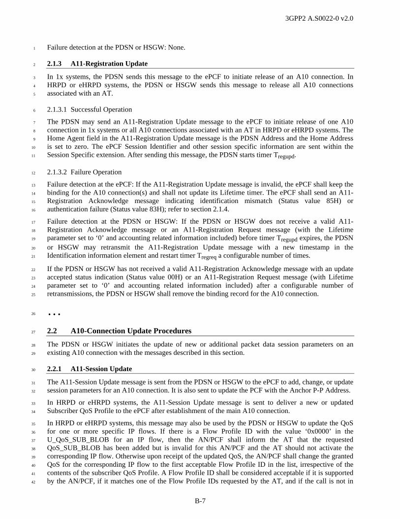
3GPP2 A.S0022-0 v2.0
B-7
Failure detection at the PDSN or HSGW: None. 1
2.1.3 A11-Registration Update 2
In 1x systems, the PDSN sends this message to the ePCF to initiate release of an A10 connection. In 3
HRPD or eHRPD systems, the PDSN or HSGW sends this message to release all A10 connections 4
associated with an AT. 5
2.1.3.1 Successful Operation 6
The PDSN may send an A11-Registration Update message to the ePCF to initiate release of one A10 7
connection in 1x systems or all A10 connections associated with an AT in HRPD or eHRPD systems. The 8
Home Agent field in the A11-Registration Update message is the PDSN Address and the Home Address 9
is set to zero. The ePCF Session Identifier and other session specific information are sent within the 10
Session Specific extension. After sending this message, the PDSN starts timer Tregupd. 11
2.1.3.2 Failure Operation 12
Failure detection at the ePCF: If the A11-Registration Update message is invalid, the ePCF shall keep the 13
binding for the A10 connection(s) and shall not update its Lifetime timer. The ePCF shall send an A11-14
Registration Acknowledge message indicating identification mismatch (Status value 85H) or 15
authentication failure (Status value 83H); refer to section 2.1.4. 16
Failure detection at the PDSN or HSGW: If the PDSN or HSGW does not receive a valid A11-17
Registration Acknowledge message or an A11-Registration Request message (with the Lifetime 18
parameter set to ‘0’ and accounting related information included) before timer Tregupd expires, the PDSN 19
or HSGW may retransmit the A11-Registration Update message with a new timestamp in the 20
Identification information element and restart timer Tregreq a configurable number of times. 21
If the PDSN or HSGW has not received a valid A11-Registration Acknowledge message with an update 22
accepted status indication (Status value 00H) or an A11-Registration Request message (with Lifetime 23
parameter set to ‘0’ and accounting related information included) after a configurable number of 24
retransmissions, the PDSN or HSGW shall remove the binding record for the A10 connection. 25
… 26
2.2 A10-Connection Update Procedures 27
The PDSN or HSGW initiates the update of new or additional packet data session parameters on an 28
existing A10 connection with the messages described in this section. 29
2.2.1 A11-Session Update 30
The A11-Session Update message is sent from the PDSN or HSGW to the ePCF to add, change, or update 31
session parameters for an A10 connection. It is also sent to update the PCF with the Anchor P-P Address. 32
In HRPD or eHRPD systems, the A11-Session Update message is sent to deliver a new or updated 33
Subscriber QoS Profile to the ePCF after establishment of the main A10 connection. 34
In HRPD or eHRPD systems, this message may also be used by the PDSN or HSGW to update the QoS 35
for one or more specific IP flows. If there is a Flow Profile ID with the value ‘0x0000’ in the 36
U_QoS_SUB_BLOB for an IP flow, then the AN/PCF shall inform the AT that the requested 37
QoS_SUB_BLOB has been added but is invalid for this AN/PCF and the AT should not activate the 38
corresponding IP flow. Otherwise upon receipt of the updated QoS, the AN/PCF shall change the granted 39
QoS for the corresponding IP flow to the first acceptable Flow Profile ID in the list, irrespective of the 40
contents of the subscriber QoS Profile. A Flow Profile ID shall be considered acceptable if it is supported 41
by the AN/PCF, if it matches one of the Flow Profile IDs requested by the AT, and if the call is not in 42

3GPP2 A.S0022-0 v2.0
B-8
inter-ePCF handoff. The AN/PCF shall store the updated QoS information received from the PDSN or 1
HSGW together with the personality index in use at the time the update was received. Whenever the 2
specified personality index is in use, the AN/PCF shall use the stored QoS update to grant the QoS 3
irrespective of the contents of the subscriber QoS Profile. All updated QoS information stored in the 4
AN/PCF for a given IP flow is cleared when the corresponding IP flow is set to null (refer to C.S0087 5
[23])7, regardless of the personality in use. 6
Updated QoS information received from the PDSN or HSGW (via the ePCF) supersedes stored updated 7
QoS information previously received from the PDSN or HSGW or from another AN (via A13 or A16). 8
In HRPD or eHRPD systems, this message is also used to release one or more IP flows by setting the 9
FlowProfile ID value to ‘0x0000’ in the Forward/Reverse Updated QoS Sub-BLOB for the IP flow that 10
the PDSN or HSGW wants to release. The PDSN or HSGW should not use this procedure for flow IDs 11
FFH and FEH. 12
In HRPD or eHRPD systems, this message may also be used by the PDSN or HSGW to update the 13
FLOW_PRIORITY for one or more specific IP flows. 14
If the A11-Session Update contains updated FLOW_PRIORITY information and the RAN can comply 15
with the updated FLOW_PRIORITY for the specified flow, the AN/PCF updates the FLOW_PRIORITY 16
granted to the specified Flow IDs. For each IP Flow updated by the PDSN or HSGW, the AN/PCF shall 17
change the FLOW_PRIORITY of that flow to the corresponding Updated FLOW_PRIORITY value in 18
the element that matches the corresponding Flow ID in the Forward/Reverse Flow Priority Update 19
Information IE, irrespective of the contents of the Subscriber QoS Profile. 20
If the AN/PCF supports Flow Priority updates, it shall store the updated FLOW_PRIORITY value 21
together with the personality index in use at the time the Flow Priority update was received from the 22
PDSN or HSGW. Whenever the specified personality index is in use, the AN/PCF shall use the updated 23
FLOW_PRIORITY value to assign the priority to the flow irrespective of the contents of the Subscriber 24
QoS Profile. 25
During dormant and active handoff, updated FLOW_PRIORITY values are transferred to the target AN 26
via A13 and A16, respectively. 27
Updated Flow Priority information received from the PDSN or HSGW (via the ePCF) supersedes stored 28
Flow Priority information previously received from the PDSN or HSGW or from another AN (via A13 or 29
A16). 30
In eHRPD systems, this message is also used to send PMK keys once they are available if the PMK 31
Indicator was included in an A11-Registration Request message for A10 establishment; however the 32
PMK Information was unavailable at the time that the corresponding A11-Registration Reply message 33
was sent or if the PMK Indicator was included in an A11-Registration Request message for A10 refresh. 34
2.2.1.1 Successful Operation 35
The PDSN or HSGW may update session parameters of an A10 connection, the Anchor P-P Address, or 36
the Subscriber QoS Profile, or update the QoS of specific flows by sending an A11-Session Update to the 37
ePCF. The Home Agent field in A11-Session Update message is the PDSN or HSGW Address and the 38
Home Address is set to zero. The ePCF Session Identifier and other session specific information are sent 39
within the Session Specific Extension. 40
The A11-Session Update message includes the session parameter(s), the Anchor P-P Address, the 41
Subscriber QoS Profile, and/or QoS Update Information in NVSE(s). In HRPD or eHRPD systems, the 42
A11-Session Update message includes the subscriber QoS profile and/or QoS Update Information and the 43
PMK Information, if requested and available. For session parameter(s), the ePCF shall update its session 44
7 i.e., ProfileType = NULL in ReservationKKQoSRequestFwd or ReservationKKQoSRequestRev.
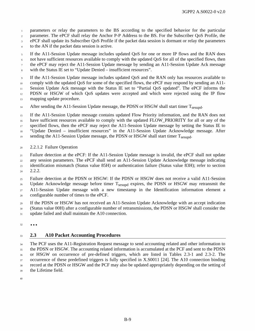
3GPP2 A.S0022-0 v2.0
B-9
parameters or relay the parameters to the BS according to the specified behavior for the particular 1
parameter. The ePCF shall relay the Anchor P-P Address to the BS. For the Subscriber QoS Profile, the 2
ePCF shall update its Subscriber QoS Profile if the packet data session is dormant or relay the parameters 3
to the AN if the packet data session is active. 4
If the A11-Session Update message includes updated QoS for one or more IP flows and the RAN does 5
not have sufficient resources available to comply with the updated QoS for all of the specified flows, then 6
the ePCF may reject the A11-Session Update message by sending an A11-Session Update Ack message 7
with the Status IE set to “Update Denied – insufficient resources”. 8
If the A11-Session Update message includes updated QoS and the RAN only has resources available to 9
comply with the updated QoS for some of the specified flows, the ePCF may respond by sending an A11-10
Session Update Ack message with the Status IE set to “Partial QoS updated”. The ePCF informs the 11
PDSN or HSGW of which QoS updates were accepted and which were rejected using the IP flow 12
mapping update procedure. 13
After sending the A11-Session Update message, the PDSN or HSGW shall start timer Tsesupd. 14
If the A11-Session Update message contains updated Flow Priority information, and the RAN does not 15
have sufficient resources available to comply with the updated FLOW_PRIORITY for all or any of the 16
specified flows, then the ePCF may reject the A11-Session Update message by setting the Status IE to 17
“Update Denied – insufficient resources” in the A11-Session Update Acknowledge message. After 18
sending the A11-Session Update message, the PDSN or HSGW shall start timer Tsesupd. 19
2.2.1.2 Failure Operation 20
Failure detection at the ePCF: If the A11-Session Update message is invalid, the ePCF shall not update 21
any session parameters. The ePCF shall send an A11-Session Update Acknowledge message indicating 22
identification mismatch (Status value 85H) or authentication failure (Status value 83H); refer to section 23
2.2.2. 24
Failure detection at the PDSN or HSGW: If the PDSN or HSGW does not receive a valid A11-Session 25
Update Acknowledge message before timer Tsesupd expires, the PDSN or HSGW may retransmit the 26
A11-Session Update message with a new timestamp in the Identification information element a 27
configurable number of times to the ePCF. 28
If the PDSN or HSGW has not received an A11-Session Update Acknowledge with an accept indication 29
(Status value 00H) after a configurable number of retransmissions, the PDSN or HSGW shall consider the 30
update failed and shall maintain the A10 connection. 31
… 32
2.3 A10 Packet Accounting Procedures 33
The PCF uses the A11-Registration Request message to send accounting related and other information to 34
the PDSN or HSGW. The accounting related information is accumulated at the PCF and sent to the PDSN 35
or HSGW on occurrence of pre-defined triggers, which are listed in Tables 2.3-1 and 2.3-2. The 36
occurrence of these predefined triggers is fully specified in X.S0011 [24]. The A10 connection binding 37
record at the PDSN or HSGW and the PCF may also be updated appropriately depending on the setting of 38
the Lifetime field. 39
40

3GPP2 A.S0022-0 v2.0
B-10
Table 2.3-1 Accounting Records Generated by the PCF in HRPD systems without IP Flow 1
Based Accounting 2
Airlink Record
Type (Y1)
Accounting Records Generated by the PCF
Y1=1 Connection Setup: Setup of A10 connection initiated
Y1=2 Active Start: A10 connection is associated with the traffic channel(s) or new parameters are set.
Y1=3 Active Stop: A10 connection is disassociated from the traffic channel(s) or parameter settings are no longer valid.
Y1=4 A forward or reverse short data burst (SDB) was exchanged with the MS. This record is not used in the HRPD system.
3
Table 2.3-2 Accounting Records Generated by the PCF in HRPD Systems with IP Flow Based 4
Accounting 5
Airlink Record
Type (Y1)
Accounting Records Generated by the PCF
Y1=1 Connection Setup: Setup of A10 connection initiated
Y1=2 Active Start: For IP flows with ID FFH, when
the main A10 connection is associated with the traffic channel; or
new parameters are set. For all other IP flows, when
both of the following become true for that IP flow: o the IP flow is in the active state, and o its associated link flow is associated with the traffic
channel; or
when new parameters are set.
Y1=3 Active Stop: For IP flows with ID FFH, when
the main A10 connection is disassociated from the traffic channel, or
parameter settings are no longer valid. For all other IP flows, when
the IP flow is in the active state and its associated link flow is associated with the traffic channel, and then one or more of the following occurs: o the traffic channel is released, o the IP flow is deactivated or removed, o its link flow is disassociated with the traffic channel; or
when parameter settings are no longer valid.
6

3GPP2 A.S0022-0 v2.0
B-11
In addition, the PCF generates an “Active Stop (Y1=3)” accounting record followed by an “Active Start 1
(Y1=2)” accounting record when certain parameters change value. Refer to section 2.3.7 for details. For 2
successful operation, the PDSN or HSGW saves the accounting related and other information for further 3
processing, and responds with an A11-Registration Reply message containing an accept indication. 4
The Airlink Record information is transferred from the PCF to the PDSN or HSGW, as Remote 5
Authentication Dial-In User Service (RADIUS) protocol encoded attributes, in the Application Data field 6
of a CVSE element. If the PDSN or HSGW receives an unexpected airlink record it may reject the A11-7
Registration Request message and the A11-Registration Reply message shall contain the code ‘86H’ 8
(Registration Denied – poorly formed request). If the PDSN or HSGW does not receive an accounting 9
parameter that is expected, the PDSN or HSGW may reject the A11-Registration Request message, and 10
the associated A11-Registration Reply message shall contain either: 11
code ‘8DH’ (Registration Denied – unsupported Vendor ID or unable to interpret Application Type or 12
Application Sub Type in the CVSE sent by the PCF to the PDSN or HSGW), or 13
code ‘86H’ (Registration Denied – poorly formed request). 14
If the PDSN or HSGW receives a RADIUS attribute that is not expected in a CVSE, the PDSN or HSGW 15
shall ignore that attribute and process the remainder of the CVSE to the extent possible. Refer to section 16
4.2.13 for further details. 17
2.3.1 A10 Connection Setup Airlink Record 18
The A10 Connection Setup Airlink record shall be included in the A11-Registration Request message at 19
the time of establishment of a new A10 connection. It is also included in the A11-Registration Request 20
message if an A10 connection is pre-setup during fast handoff. 21
In HRPD systems, if a single A11-Registration Request message is used to establish multiple A10 22
connections, an A10 Connection Setup Airlink record is included for each of the A10 connections to be 23
established. 24
2.3.2 Active-Start Airlink Record 25
The Active-Start Airlink record shall be included in the A11-Registration Request message under the 26
following circumstances: 27
1. For 1x systems when a traffic channel is assigned to a packet data service instance: during initial 28
service instance setup when the service instance becomes associated with the air interface, on 29
transition from dormant to active state or during handoff, or for an HRPD system when the air 30
interface is in an appropriate state such that bearer data is ready to be exchanged. The Active-Start 31
Airlink record may follow the A10 Connection Setup Airlink record in the same A11-Registration 32
Request message (assuming that all the parameters required in the Active-Start Airlink record are 33
made available at the ePCF at the time the message is sent). 34
2. Following an Active-Stop Airlink record when any of the parameters specified in section 2.3.7 are 35
changed. The Active Start Airlink Record shall contain the new set of parameters. 36
3. For IP flows with ID FFH or FEH8 in HRPD systems, when an HRPD connection is established: 37
during initial session setup when the main A10 connection is associated with the HRPD air interface, 38
on transition from dormant to active state, or during handoff. The Active Start Airlink Record for the 39
IP flows with ID FFH or FEH shall not be sent to the HSGW if the Tunnel Mode indication set to ‘1’ 40
in eHRPD Indicators is also included in the A11-Registration Request message. For IP flows with ID 41
FFH or FEH in HRPD systems, accounting is bidirectional: one Active-Start Airlink record applies to 42
8 FEH is optional, depending on whether or not the AN chooses to configure the session to use it.

3GPP2 A.S0022-0 v2.0
B-12
both forward and reverse IP flows with ID FFH or FEH. This record does not include Granted QoS 1
Parameters. 2
4. For IP flows with ID other than FFH or FEH in HRPD systems, when transitioning to a state where 3
the IP flow is in the active state and its associated link flow is associated with the traffic channel. For 4
IP flows with ID other than FFH or FEH in HRPD systems, accounting is unidirectional: separate 5
Active-Start Airlink records are generated per {IP flow, Direction} pair. This record shall include 6
Granted QoS Parameters. 7
In HRPD systems, the Active-Start Airlink record may follow the A10 connection Setup Airlink record in 8
the same A11-Registration Request message (assuming that all the parameters required in the Active-Start 9
Airlink record are made available at the ePCF at the time the message is sent). The ePCF shall not send an 10
IP flow active start before sending connection setup for the A10 connection carrying that IP flow. 11
2.3.3 Active-Stop Airlink Record 12
The Active Stop Airlink Record shall be included in the A11-Registration Request message under the 13
following circumstances: 14
1. In 1x systems, when the traffic channel is disassociated from the packet data service instance: during 15
service instance release, on transition from active state to dormant, or during handoff. 16
2. When any of the parameters specified in section 2.3.7 are changed. 17
3. For IP flows in HRPD systems, when the HRPD connection (traffic channel) is released. 18
4. For IP flows with ID FFH or FEH8 in HRPD systems, when an HRPD connection is released. The 19
Active-Stop Airlink Record for the IP flows with ID FFH or FEH shall not be sent to the HSGW if 20
the Tunnel Mode indication with the value set to ‘1’ is also included in the A11-Registration Request 21
message. For IP flows with ID FFH or FEH in HRPD systems, accounting is bidirectional: one 22
Active-Stop Airlink record applies to both forward and reverse IP flows with ID FFH or FEH. This 23
record does not include Flow ID Parameter and Flow Status. 24
5. For IP flows with ID other than FFH in HRPD systems, when the IP flow is removed or transitions to 25
the deactivated state while its associated link flow is associated with the traffic channel, during 26
handoff, or when the IP flow’s associated link flow is disassociated with the traffic channel while the 27
IP flow is in the activated state. For IP flows with ID other than FFH in HRPD systems, accounting is 28
unidirectional: separate Active-Stop Airlink records are generated per {IP flow, Direction} pair. 29
For inter-ePCF handoff, the source ePCF shall send an Active-Stop Airlink record for each activated IP 30
flow to the PDSN, and the target ePCF shall send Active-Start Airlink records for each activated IP flow 31
to the PDSN. In the case of circumstance (2) above, the Active Stop Airlink Record shall be sent and 32
followed by an Active Start Airlink Record that shall contain the new set of parameters. 33
… 34
3.0 Message Formats 35
36
3.1 A11-Registration Request 37
This A11 interface message is sent from the ePCF to the HSGW to: 38
establish one or more A10 connection (and identify the associated service option value and MN 39
Session Reference ID/SR_ID); 40
establish a connection for HRPD pre-registration while the AT is on E-UTRAN; 41
periodically re-register all A10 connection(s) for the MS/eAT; 42
clear one or more A10 connection(s); 43

3GPP2 A.S0022-0 v2.0
B-13
pass accounting related information per the triggers listed in Table 2.3-1 and Table 2.3-2; 1
perform any additions, deletions, remappings, and/or changes in granted QoS of IP flows in HRPD 2
and eHRPD systems; 3
Request APN information from the HSGW in eHRPD systems. 4
The A11-Registration Request messages may contain additional information to: 5
pass inter-HSGW handoff, or inter-technology handoff related information; 6
indicate support of features such as Short Data Indication; 7
pass information related to E-UTRAN – eHRPD handoff; 8
indicate that the eAT is operating in evolved mode; 9
pass information applicable to calls in eHRPD mode, such as a request for PMK information. 10
11
Information Element Section Reference
Element Direction Type
A11 Message Type [3], [4] ePCF -> HSGW M
Flags [3], [4] ePCF -> HSGW O R
Lifetime [3], [4] ePCF -> HSGW Oh R
Home Address [3], [4] ePCF -> HSGW O R
Home Agent [3], [4] ePCF -> HSGW O R
Care-of-Address [3], [4] ePCF -> HSGW Ol R
Identification [3], [4] ePCF -> HSGW O R
Session Specific Extension [3], [4] ePCF -> HSGW Oi R
Critical Vendor/Organization Specific Extension [3], [4] ePCF -> HSGW Oa,e C
Normal Vendor/Organization Specific Extension 4.2.14 ePCF -> HSGW Oa,b,c,d,f,g,j,k,m,
n,o,p,q,r,s,t,u C
Mobile-Home Authentication Extension [3], [4] ePCF -> HSGW O R
a. One or more instances of this element may be included. 12
b. In 1x systems, during a fast handoff, this element is used to provide the Anchor P-P Address to the 13
target PDSN when the PCF supports fast handoff. If an Anchor P-P Address is included in the 14
message and the PDSN supports fast handoff, then the PDSN shall process the fast handoff request, 15
and disregard the ANID values. 16
c. In 1x systems, if this message contains the Active Stop Airlink Record for the last service instance 17
going dormant (i.e., all packet data service instances for the user are dormant) in the CVSE, then an 18
instance of this element containing the All Dormant Indicator shall be included in this message. 19
d. In HRPD and eHRPD systems, Application Type = Service Option contains the SO value for the 20
main service connection. The main service connection is defined to have SR_ID=1. 21
e. During a handoff, this element is used to provide the MEI. 22
f. During a handoff, this element is used to provide the ANIDs. 23
g. This element may indicate the features that the ePCF has enabled e.g., Short Data Indication. 24
h. For HRPD and eHRPD systems, Lifetime applies to all A10 connections set up by this message when 25
this message is sent. If the lifetime field is set to ‘0’, all A10 connections associated with the HRPD 26
session are released. 27
i. In HRPD and eHRPD systems, this IE contains information for the main service connection. 28

3GPP2 A.S0022-0 v2.0
B-14
j. If the PCF supports ANIDs, then this IE shall be included to convey the Access Network Identifiers 1
to the PDSN. 2
k. For HRPD and eHRPD systems, this IE may be used to set up auxiliary A10 connections. When 3
setting up auxiliary A10 connections, this IE is also used to send information for all existing A10 4
connections. 5
l. For HRPD and eHRPD systems, this IE contains the IPv4 address of the ePCF that terminates the 6
main A10 connection (identified in the Session Specific Extension IE). Note that this address may be 7
different from the source IP address of this message. 8
m. For HRPD and eHRPD, this IE may be included to specify IP flows associated with the A10 9
connections and to convey QoS information for those IP flows (Flow State, Requested QoS, and 10
Granted QoS). Each instance of this IE with QoS Information application type contains QoS 11
information for IP flows associated with one direction of one A10 connection. Multiple instances of 12
the QoS Information application type NVSE are used for transmission of QoS Information in both 13
directions of an A10 connection and for multiple A10 connections (i.e., multiple SR_IDs) in the same 14
A11-Registration Request message. 15
n. For HRPD and eHRPD systems, this IE is used to provide QoS information. 16
o. In HRPD and eHRPD systems, the QoS Mode Session Parameter shall be included in an NVSE when 17
this message is sent for setting up the main A10 connection, to indicate QoS mode. For enhanced 18
mode sessions, the ePCF shall set the QoS Mode Session Parameter to the value 01H. If the PDSN 19
does not receive the QoS Mode, then the PDSN shall assume the QoS Mode is set to ‘0’. 20
p. This IE shall be included when this message is sent to convey information pertaining to the E-21
UTRAN – eHRPD handoff such as P-GW Addresses and GRE keys for uplink traffic. 22
q. For inter-HSGW mobility in eHRPD systems, the target ePCF shall include the source HSGW’s 23
HSGW H1 IP Address. The target ePCF may include this IE if it is available. 24
r. For handoff from E-UTRAN to eHRPD, the target ePCF shall include information for the eAT’s EPS 25
information. 26
s. For eHRPD, this element may be included to convey eHRPD Indicators. For an eHRPD system that 27
supports GKE, the PMK indication may be set to ‘1’ to request PMK information, for example when 28
establishing the main A10 connection upon setup, refreshing the A10 connection or during inter-29
HSGW mobility. The ePCF shall not send eHRPD Indicators if the mobile is operating in legacy 30
mode. 31
t. For eHRPD, an instance of this element containing the eHRPD Mode indication shall be included in 32
this message when establishing the main A10 connection if the HSGW A11 IP address is shared with 33
PDSN The eHRPD Mode indication informs the receiver if it should operate as a PDSN or an 34
HSGW. 35
u. For handoff from eHRPD to E-UTRAN, an instance of this element containing the E-UTRAN 36
Handoff Parameter Request indication may be included to request parameters. 37
The following table shows the bitmap layout for the A11-Registration Request message. 38
3.1 A11-Registration Request
0 1 2 3 4 5 6 7 Octet
A11 Message Type = [01H] 1
Flags = [0AH, 8AH] 1
(MSB) Lifetime = [00 00H to FF FEH] 1
(LSB) 2

3GPP2 A.S0022-0 v2.0
B-15
3.1 A11-Registration Request
0 1 2 3 4 5 6 7 Octet
(MSB) Home Address = [00 00 00 00H] 1
2
3
(LSB) 4
(MSB) Home Agent = <any value> 1
2
3
(LSB) 4
(MSB) Care-of-Address = <any value> 1
2
3
(LSB) 4
(MSB) Identification = <any value> 1
2
3
4
5
6
7
(LSB) 8
Session Specific Extension: = [27H] 1
Length = [13H–15H] 2
(MSB) Protocol Type = [88 81H] 3
(LSB) 4
(MSB) Key = <any value> 5
6
7
(LSB) 8
Reserved = [00H] 9
Reserved = [0000 00] Session ID Ver = [‘00’ (Version 0),
‘01’ (Version 1)]
10
(MSB) MN Session Reference Id = [00 01H - 00 06H], in 1x systems [00 01H] in HRPD and eHRPD systems
11
(LSB) 12
(MSB) MSID Type = [00 01H (MEID), 00 05H (ESN), 00 06H (IMSI)] 13
(LSB) 14
MSID Length = [06-08H] 15
IF (MSID Type = 00 06H), MSID{1:

3GPP2 A.S0022-0 v2.0
B-16
3.1 A11-Registration Request
0 1 2 3 4 5 6 7 Octet
Identity Digit 1 = [0H-9H] (BCD) Odd/Even Indicator = [0000, 0001] 16
Identity Digit 3 = [0H-9H] (BCD) Identity Digit 2 = [0H-9H] (BCD) 17
… … …
If (Odd/Even Indicator = 0000 (even)) {Identity Digit N+1 = [FH] (BCD)}
Else If (Odd/Even Indicator = 0001 (odd)) {Identity Digit N+1 = [0H-9H] (BCD)}
Identity Digit N = [0H-9H] (BCD) k
} OR IF (MSID Type = 00 05H), MSID{1:
(MSB) ESN = <any value> 4
5
6
(LSB) 7
} OR IF (MSID Type = 00 01H), MSID{1:
MEID Hex Digit 3 = [0H-FH] MEID Hex Digit 2 = [0H-FH] 4
MEID Hex Digit 5 = [0H-FH] MEID Hex Digit 4 = [0H-FH] 5
MEID Hex Digit 7 = [0H-FH] MEID Hex Digit 6 = [0H-FH] 6
MEID Hex Digit 9 = [0H-FH] MEID Hex Digit 8 = [0H-FH] 7
MEID Hex Digit 11 = [0H-FH] MEID Hex Digit 10 = [0H-FH] 8
MEID Hex Digit 13 = [0H-FH] MEID Hex Digit 12 = [0H-FH] 9
Fill = [FH] MEID Hex Digit 14 = [0H-FH] 10
}MSID Type
Critical Vendor/Organization Specific Extension: Type = [26H] 1
Reserved = [0000 0000] 2
(MSB) Length = <variable> 3
(LSB) 4
(MSB) 3GPP2 Vendor ID = 00 00 15 9FH 5
6
7
(LSB) 8
Application Type = [01H, 02H] 9
IF (Application Type = 01H (Accounting) {1:
Application Sub Type = [01H] 10
(MSB) Application Data (contains accounting information) 11
…
(LSB) k
} Application Type = 01H; ELSE IF (Application Type = 02H (Mobility Event Indicator)) {1:
Application Sub Type = [01H] m
} Application Type = 02H

3GPP2 A.S0022-0 v2.0
B-17
3.1 A11-Registration Request
0 1 2 3 4 5 6 7 Octet
Normal Vendor/Organization Specific Extension: Type = [86H] 1
Length = <variable> 2
(MSB) Reserved = [00 00H] 3
(LSB) 4
(MSB) 3GPP2 Vendor ID = [00 00 15 9FH] 5
6
7
(LSB) 8
Application Type = [06H, 08H, 09H, 0B-0DH, 0FH] (Indicators, Session Parameter, Service Option, PCF Enabled Features,
Additional Session Information, QoS Information, Information)
9
IF (Application Type = 06H (Indicators)) {1
Application Sub Type = [02H (eHRPD Mode),
03H (eHRPD Indicators)]
10
IF (Application Sub Type = 02H (eHRPD Mode)){1:
Reserved = [000 0000H] eHRPD Mode =
[0,1]
11
} Application Sub Type = 02H; ELSE IF (Application Sub Type = 03H (eHRPD Indicators)){1:
Reserved = [0 0000H] PMK = [0,1]
E-UTRAN Handoff Info = [0,1]
Tunnel Mode =
[0,1]
11
} Application Sub Type = 03H;
} Application Type = 06H; ELSE IF (Application Type = 08H (Session Parameter)) {1
Application Sub Type = 03H (QoS Mode) 10
QoS Mode = [00H-01H] 11
} Application Type = 08H; ELSE IF (Application Type = 09H (Service Option)) {1:
Application Sub Type = [01H] 10
(MSB) Application Data = [00 3BH (HRPD main service instance)] for HRPD and eHRPD systems
11
(LSB) 12
} Application Type = 09H; ELSE IF (Application Type = 0BH (PCF Enabled Features)){1
Application Sub Type = [01H (Short Data Indication Supported), 02H (GRE Segment Enabled)]
10
} Application Type = 0BH; ELSE IF (Application Type = 0CH (Additional Session Information)) {1:
Application Sub Type = [01H] 10
GRE Key Information Entry { 1-30:
Entry Length = <variable> n
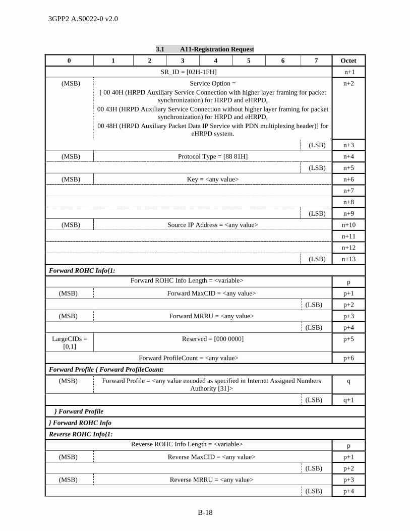
3GPP2 A.S0022-0 v2.0
B-18
3.1 A11-Registration Request
0 1 2 3 4 5 6 7 Octet
SR_ID = [02H-1FH] n+1
(MSB) Service Option = [ 00 40H (HRPD Auxiliary Service Connection with higher layer framing for packet
synchronization) for HRPD and eHRPD, 00 43H (HRPD Auxiliary Service Connection without higher layer framing for packet
synchronization) for HRPD and eHRPD, 00 48H (HRPD Auxiliary Packet Data IP Service with PDN multiplexing header)] for
eHRPD system.
n+2
(LSB) n+3
(MSB) Protocol Type = [88 81H] n+4
(LSB) n+5
(MSB) Key = <any value> n+6
n+7
n+8
(LSB) n+9
(MSB) Source IP Address = <any value> n+10
n+11
n+12
(LSB) n+13
Forward ROHC Info{1:
Forward ROHC Info Length = <variable> p
(MSB) Forward MaxCID = <any value> p+1
(LSB) p+2
(MSB) Forward MRRU = <any value> p+3
(LSB) p+4
LargeCIDs = [0,1]
Reserved = [000 0000] p+5
Forward ProfileCount = <any value> p+6
Forward Profile { Forward ProfileCount:
(MSB) Forward Profile = <any value encoded as specified in Internet Assigned Numbers Authority [31]>
q
(LSB) q+1
} Forward Profile
} Forward ROHC Info
Reverse ROHC Info{1:
Reverse ROHC Info Length = <variable> p
(MSB) Reverse MaxCID = <any value> p+1
(LSB) p+2
(MSB) Reverse MRRU = <any value> p+3
(LSB) p+4

3GPP2 A.S0022-0 v2.0
B-19
3.1 A11-Registration Request
0 1 2 3 4 5 6 7 Octet
Reverse LargeCIDs =
[0,1]
Reserved = [000 0000] p+5
Reverse ProfileCount = <any value> p+6
Reverse Profile { Reverse ProfileCount:
(MSB) Reverse Profile = <any value encoded as specified in Internet Assigned Numbers Authority [31]>
q
(LSB) q+1
} Reverse Profile
} Reverse ROHC Info
} GRE Key Information Entry
} Application Type = 0CH; ELSE IF (Application Type = 0DH (QoS Information)){1:
Application Sub Type = [01H - 02H] 10
IF (Application Sub Type = 01H (Forward QoS Information)){1:
SR_ID = [01H-1FH] 11
Use IP Flow Discrimination
= [0,1]
DSCP Included =
[0,1]
Reserved = [00 0000] 12
Reserved = [000] Forward Flow Count = [1 – 31] 13
Forward Flow Entry { Forward Flow Count :
Entry Length = [variable] n
Forward Flow ID = [00H - FFH] n+1
Reserved DSCP Flow State = [0, 1]
n+2
Forward Requested QoS Length = [variable] n+3
(MSB) Forward Requested QoS = <any value> n+4
… …
(LSB) p
Forward Granted QoS Length = [variable] p+1
(MSB) Forward Granted QoS = <any value> p+2
… …
(LSB) q
} Forward Flow Entry
} Application Sub Type = 01H; ELSE IF (Application Sub Type = 02H (Reverse QoS Information)){1:
SR_ID = [01H-1FH] 11
Reserved = [000] Reverse Flow Count = [1 – 31] 12
Reverse Flow Entry { Reverse Flow Count :
Entry Length = [variable] n
Reverse Flow ID = [00H - FFH] n+1
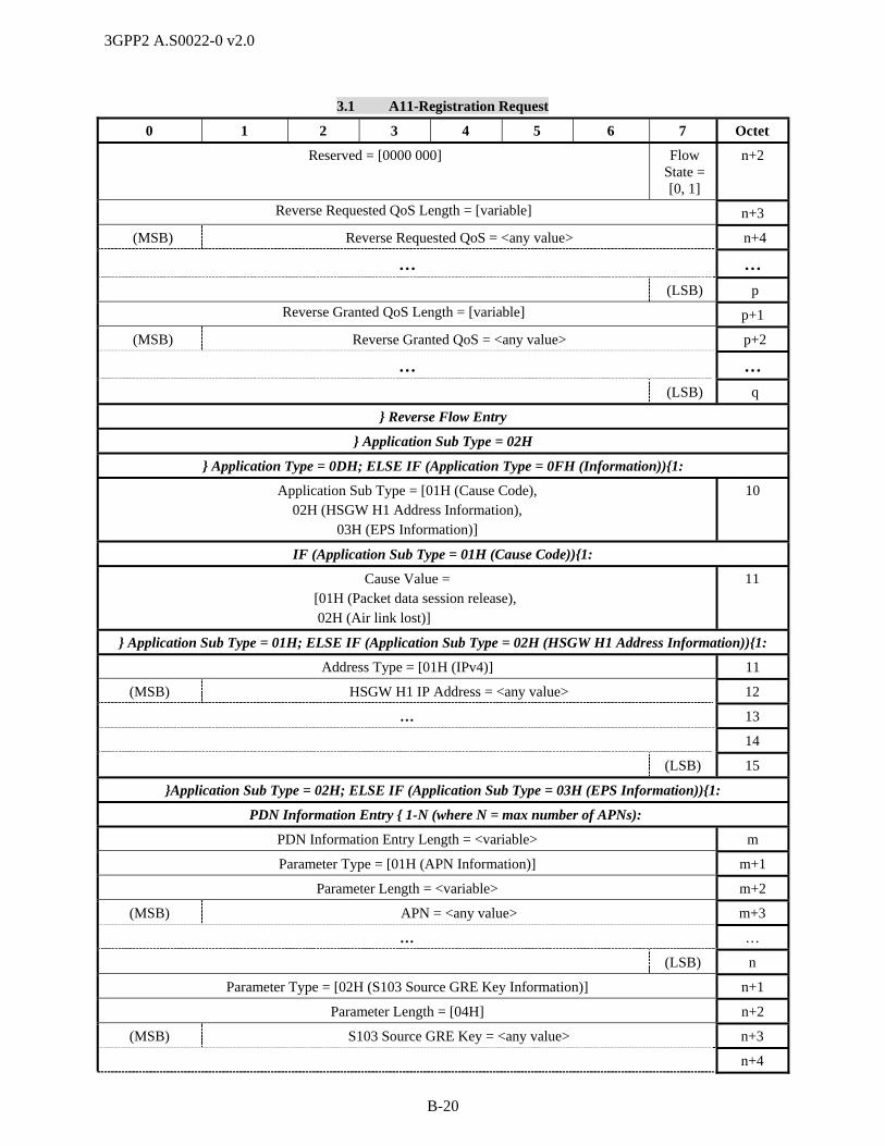
3GPP2 A.S0022-0 v2.0
B-20
3.1 A11-Registration Request
0 1 2 3 4 5 6 7 Octet
Reserved = [0000 000] Flow State = [0, 1]
n+2
Reverse Requested QoS Length = [variable] n+3
(MSB) Reverse Requested QoS = <any value> n+4
… …
(LSB) p
Reverse Granted QoS Length = [variable] p+1
(MSB) Reverse Granted QoS = <any value> p+2
… …
(LSB) q
} Reverse Flow Entry
} Application Sub Type = 02H
} Application Type = 0DH; ELSE IF (Application Type = 0FH (Information)){1:
Application Sub Type = [01H (Cause Code), 02H (HSGW H1 Address Information),
03H (EPS Information)]
10
IF (Application Sub Type = 01H (Cause Code)){1:
Cause Value = [01H (Packet data session release), 02H (Air link lost)]
11
} Application Sub Type = 01H; ELSE IF (Application Sub Type = 02H (HSGW H1 Address Information)){1:
Address Type = [01H (IPv4)] 11
(MSB) HSGW H1 IP Address = <any value> 12
… 13
14
(LSB) 15
}Application Sub Type = 02H; ELSE IF (Application Sub Type = 03H (EPS Information)){1:
PDN Information Entry { 1-N (where N = max number of APNs):
PDN Information Entry Length = <variable> m
Parameter Type = [01H (APN Information)] m+1
Parameter Length = <variable> m+2
(MSB) APN = <any value> m+3
… …
(LSB) n
Parameter Type = [02H (S103 Source GRE Key Information)] n+1
Parameter Length = [04H] n+2
(MSB) S103 Source GRE Key = <any value> n+3
n+4
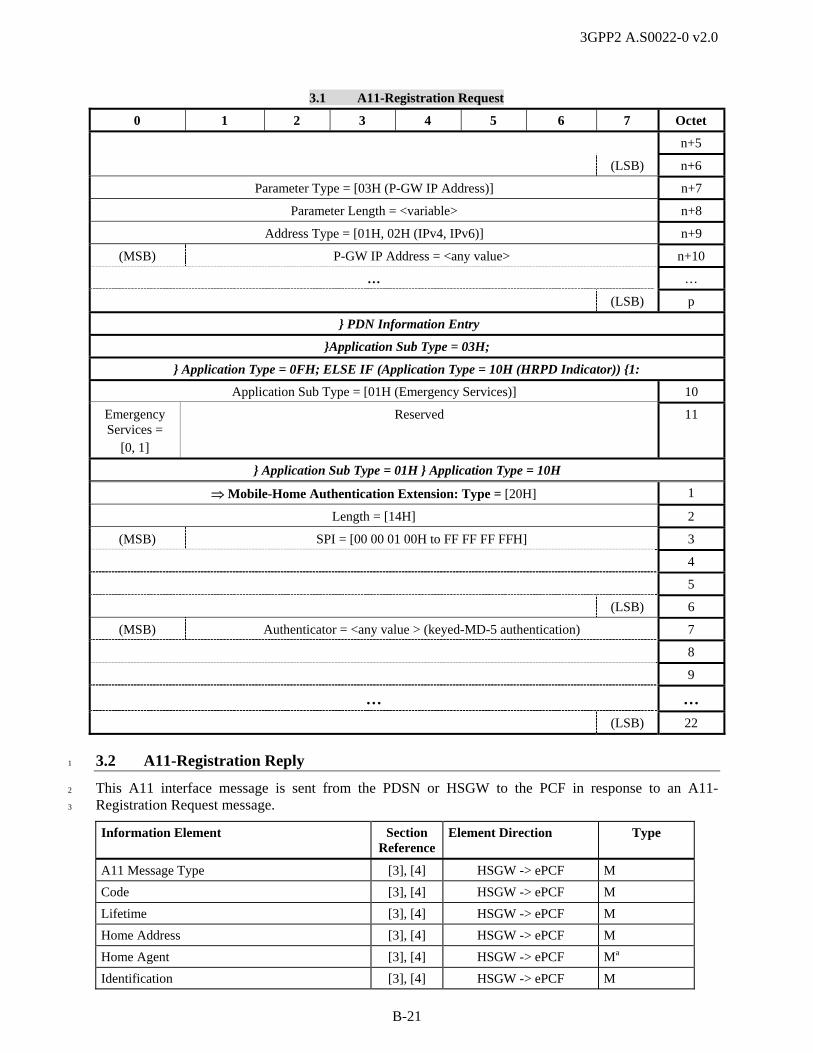
3GPP2 A.S0022-0 v2.0
B-21
3.1 A11-Registration Request
0 1 2 3 4 5 6 7 Octet
n+5
(LSB) n+6
Parameter Type = [03H (P-GW IP Address)] n+7
Parameter Length = <variable> n+8
Address Type = [01H, 02H (IPv4, IPv6)] n+9
(MSB) P-GW IP Address = <any value> n+10
… …
(LSB) p
} PDN Information Entry
}Application Sub Type = 03H;
} Application Type = 0FH; ELSE IF (Application Type = 10H (HRPD Indicator)) {1:
Application Sub Type = [01H (Emergency Services)] 10
Emergency Services =
[0, 1]
Reserved 11
} Application Sub Type = 01H } Application Type = 10H
Mobile-Home Authentication Extension: Type = [20H] 1
Length = [14H] 2
(MSB) SPI = [00 00 01 00H to FF FF FF FFH] 3
4
5
(LSB) 6
(MSB) Authenticator = <any value > (keyed-MD-5 authentication) 7
8
9
… …
(LSB) 22
3.2 A11-Registration Reply 1
This A11 interface message is sent from the PDSN or HSGW to the PCF in response to an A11-2
Registration Request message. 3
Information Element Section Reference
Element Direction Type
A11 Message Type [3], [4] HSGW -> ePCF M
Code [3], [4] HSGW -> ePCF M
Lifetime [3], [4] HSGW -> ePCF M
Home Address [3], [4] HSGW -> ePCF M
Home Agent [3], [4] HSGW -> ePCF Ma
Identification [3], [4] HSGW -> ePCF M

3GPP2 A.S0022-0 v2.0
B-22
Information Element Section Reference
Element Direction Type
Session Specific Extension [3], [4] HSGW -> ePCF Mi
Critical Vendor/Organization Specific Extension [3], [4] HSGW -> ePCF Ob C
Normal Vendor/Organization Specific Extension 4.2.14 HSGW -> ePCF Oc,d,e,f,g,
h,j,k,l,m,n,o
,p,q
C
Mobile-Home Authentication Extension [3], [4] HSGW -> ePCF O R
1
a. This element can also be used to identify the IPv4 address of an alternative PDSN or HSGW. 2
b. This element is included if the PDSN or HSGW has data available. 3
c. In 1x systems, this element is used by the anchor PDSN to provide an Anchor P-P Address when the 4
PDSN supports fast handoff. 5
d. One or more instances of this element may be included. 6
e. In 1x systems during a fast handoff, the target PDSN includes the Anchor P-P Address to indicate that 7
the fast handoff request was accepted. 8
f. In 1x and HRPD systems, this element is used to send a Radio Network Packet Data Inactivity Timer 9
(RN-PDIT) to the PCF when supported. 10
g. When an Always-on Indicator is present at the PDSN or HSGW, the PDSN or HSGW shall include 11
the NVSE with an Always-on indicator. 12
h. This element is used by the PDSN or HSGW to indicate that flow control is enabled for the packet 13
data service instance. 14
i. In 1x systems, this IE contains information for the main service instance. In HRPD and eHRPD 15
systems, this IE contains information for the main service connection. 16
j. If this message is sent to establish the main A10 connection during dormant handoff in an HRPD or 17
eHRPD system, the PDSN or HSGW shall include the NVSE with the saved Subscriber QoS Profile, 18
if any. 19
k. This IE contains information (in the Additional Session Information application type) for auxiliary 20
A10 connection(s) requested in the corresponding A11-Registration Request message. 21
l. In HRPD and eHRPD systems with QoS, this element is included by the PDSN or HSGW when this 22
message is sent to establish the main A10 connection. It provides the PDSN or HSGW ROHC 23
channel parameter values when ROHC on SO67 is supported with ROHC in the PDSN or HSGW. 24
m. This IE may be used to indicate that the PDSN or HSGW supports receiving the GRE segmentation 25
attribute in A10 GRE frames. 26
n. If this message is sent to establish the main A10 connection in an eHRPD system, the HSGW shall 27
include this IE to convey its H1 IP Address. This information is saved in the event of an inter-HSGW 28
handoff. 29
o. In eHRPD systems, this element is included by the HSGW to provide the Target HSGW S103 30
Information when this message is sent in response to an A11-Registration Request message 31
containing the user’s APN Information. This information is used for handoff from E-UTRAN to 32
eHRPD. The Serving GW uses this information to forward any stranded packets to the HSGW over 33
the S103 tunnel. 34
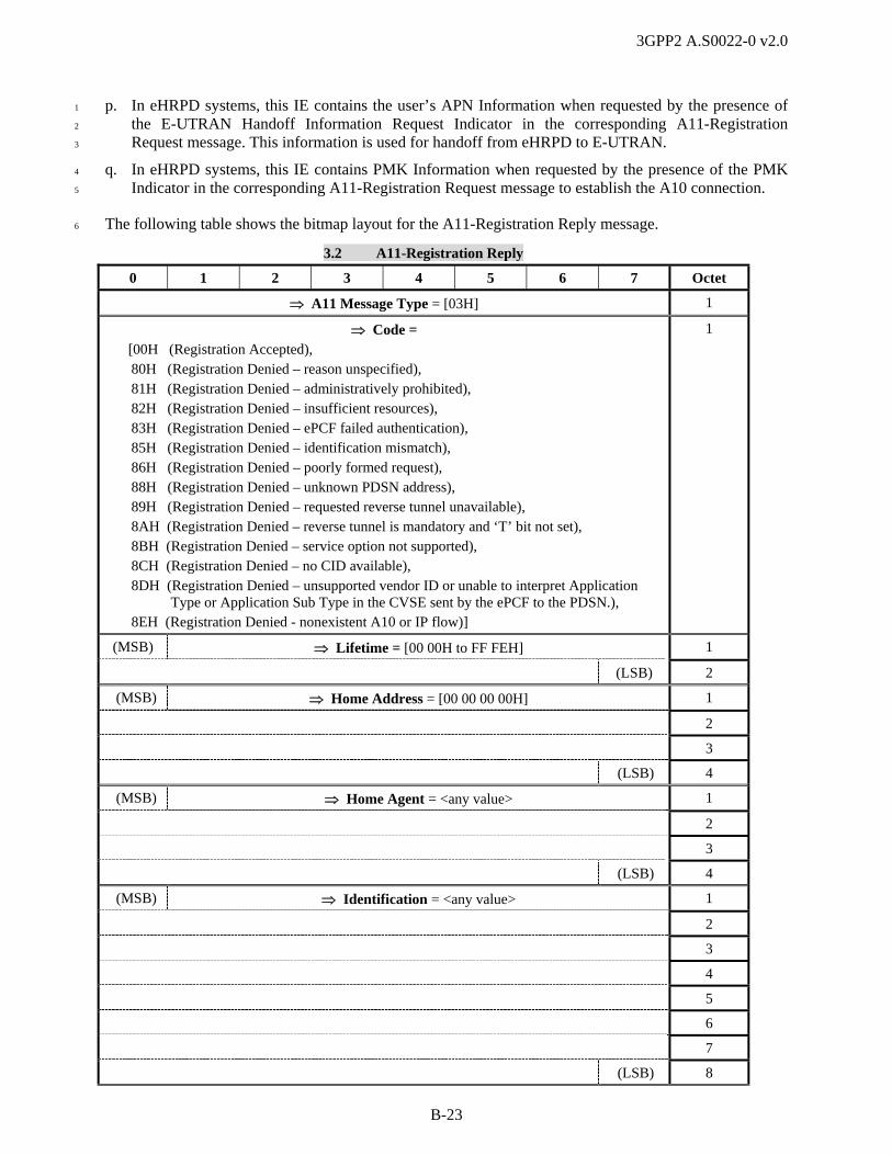
3GPP2 A.S0022-0 v2.0
B-23
p. In eHRPD systems, this IE contains the user’s APN Information when requested by the presence of 1
the E-UTRAN Handoff Information Request Indicator in the corresponding A11-Registration 2
Request message. This information is used for handoff from eHRPD to E-UTRAN. 3
q. In eHRPD systems, this IE contains PMK Information when requested by the presence of the PMK 4
Indicator in the corresponding A11-Registration Request message to establish the A10 connection. 5
The following table shows the bitmap layout for the A11-Registration Reply message. 6
3.2 A11-Registration Reply
0 1 2 3 4 5 6 7 Octet
A11 Message Type = [03H] 1
Code = [00H (Registration Accepted),
80H (Registration Denied – reason unspecified), 81H (Registration Denied – administratively prohibited), 82H (Registration Denied – insufficient resources), 83H (Registration Denied – ePCF failed authentication), 85H (Registration Denied – identification mismatch), 86H (Registration Denied – poorly formed request), 88H (Registration Denied – unknown PDSN address), 89H (Registration Denied – requested reverse tunnel unavailable), 8AH (Registration Denied – reverse tunnel is mandatory and ‘T’ bit not set), 8BH (Registration Denied – service option not supported), 8CH (Registration Denied – no CID available), 8DH (Registration Denied – unsupported vendor ID or unable to interpret Application
Type or Application Sub Type in the CVSE sent by the ePCF to the PDSN.), 8EH (Registration Denied - nonexistent A10 or IP flow)]
1
(MSB) Lifetime = [00 00H to FF FEH] 1
(LSB) 2
(MSB) Home Address = [00 00 00 00H] 1
2
3
(LSB) 4
(MSB) Home Agent = <any value> 1
2
3
(LSB) 4
(MSB) Identification = <any value> 1
2
3
4
5
6
7
(LSB) 8
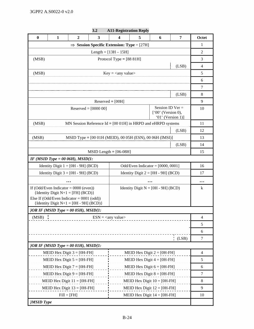
3GPP2 A.S0022-0 v2.0
B-24
3.2 A11-Registration Reply
0 1 2 3 4 5 6 7 Octet
Session Specific Extension: Type = [27H] 1
Length = [13H – 15H] 2
(MSB) Protocol Type = [88 81H] 3
(LSB) 4
(MSB) Key = <any value> 5
6
7
(LSB) 8
Reserved = [00H] 9
Reserved = [0000 00] Session ID Ver = [‘00’ (Version 0),
‘01’ (Version 1)]
10
(MSB) MN Session Reference Id = [00 01H] in HRPD and eHRPD systems 11
(LSB) 12
(MSB) MSID Type = [00 01H (MEID), 00 05H (ESN), 00 06H (IMSI)] 13
(LSB) 14
MSID Length = [06-08H] 15
IF (MSID Type = 00 06H), MSID{1:
Identity Digit 1 = [0H - 9H] (BCD) Odd/Even Indicator = [0000, 0001] 16
Identity Digit 3 = [0H - 9H] (BCD) Identity Digit 2 = [0H - 9H] (BCD) 17
… … …
If (Odd/Even Indicator = 0000 (even)) {Identity Digit N+1 = [FH] (BCD)} Else If (Odd/Even Indicator = 0001 (odd)) {Identity Digit N+1 = [0H - 9H] (BCD)}
Identity Digit N = [0H - 9H] (BCD) k
}OR IF (MSID Type = 00 05H), MSID{1:
(MSB) ESN = <any value> 4
5
6
(LSB) 7
}OR IF (MSID Type = 00 01H), MSID{1:
MEID Hex Digit 3 = [0H-FH] MEID Hex Digit 2 = [0H-FH] 4
MEID Hex Digit 5 = [0H-FH] MEID Hex Digit 4 = [0H-FH] 5
MEID Hex Digit 7 = [0H-FH] MEID Hex Digit 6 = [0H-FH] 6
MEID Hex Digit 9 = [0H-FH] MEID Hex Digit 8 = [0H-FH] 7
MEID Hex Digit 11 = [0H-FH] MEID Hex Digit 10 = [0H-FH] 8
MEID Hex Digit 13 = [0H-FH] MEID Hex Digit 12 = [0H-FH] 9
Fill = [FH] MEID Hex Digit 14 = [0H-FH] 10
}MSID Type
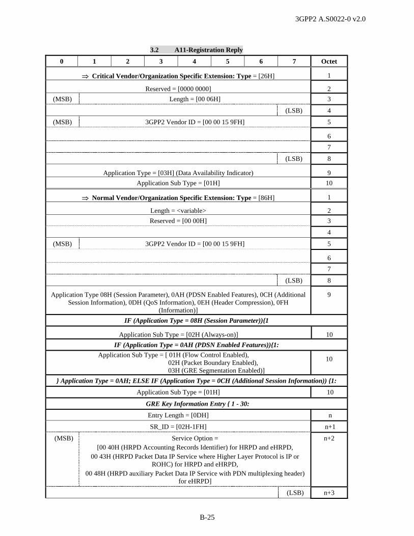
3GPP2 A.S0022-0 v2.0
B-25
3.2 A11-Registration Reply
0 1 2 3 4 5 6 7 Octet
Critical Vendor/Organization Specific Extension: Type = [26H] 1
Reserved = [0000 0000] 2
(MSB) Length = [00 06H] 3
(LSB) 4
(MSB) 3GPP2 Vendor ID = [00 00 15 9FH] 5
6
7
(LSB) 8
Application Type = [03H] (Data Availability Indicator) 9
Application Sub Type = [01H] 10
Normal Vendor/Organization Specific Extension: Type = [86H] 1
Length = <variable> 2
Reserved = [00 00H] 3
4
(MSB) 3GPP2 Vendor ID = [00 00 15 9FH] 5
6
7
(LSB) 8
Application Type 08H (Session Parameter), 0AH (PDSN Enabled Features), 0CH (Additional Session Information), 0DH (QoS Information), 0EH (Header Compression), 0FH
(Information)]
9
IF (Application Type = 08H (Session Parameter)){1
Application Sub Type = [02H (Always-on)] 10
IF (Application Type = 0AH (PDSN Enabled Features)){1:
Application Sub Type = [ 01H (Flow Control Enabled), 02H (Packet Boundary Enabled), 03H (GRE Segmentation Enabled)]
10
} Application Type = 0AH; ELSE IF (Application Type = 0CH (Additional Session Information)) {1:
Application Sub Type = [01H] 10
GRE Key Information Entry { 1 - 30:
Entry Length = [0DH] n
SR_ID = [02H-1FH] n+1
(MSB) Service Option = [00 40H (HRPD Accounting Records Identifier) for HRPD and eHRPD,
00 43H (HRPD Packet Data IP Service where Higher Layer Protocol is IP or ROHC) for HRPD and eHRPD,
00 48H (HRPD auxiliary Packet Data IP Service with PDN multiplexing header) for eHRPD]
n+2
(LSB) n+3

3GPP2 A.S0022-0 v2.0
B-26
3.2 A11-Registration Reply
0 1 2 3 4 5 6 7 Octet
(MSB) Protocol Type = [88 81H] n+4
(LSB) n+5
(MSB) Key = <any value> n+6
n+7
n+8
(LSB) n+9
(MSB) Source IP Address = <any value> n+10
n+11
n+12
(LSB) n+13
} GRE Key Information Entry
} Application Type = 0CH; ELSE IF (Application Type = 0DH (QoS Information)) {1:
Application Sub Type = [03H (Subscriber QoS Profile)] 10
(MSB) Subscriber QoS Profile = <any value> 11
12
13
… …
(LSB) n
} Application Type = 0DH; ELSE IF (Application Type = 0EH (Header Compression) {1:
Application Sub Type = [01H (ROHC Configuration Parameters)] 10
(MSB) MaxCID = <any value> 11
(LSB) 12
(MSB) MRRU = <any value> 13
(LSB) 14
LargeCIDs = [0,1]
Reserved = [000 0000] 15
ProfileCount = <any value> 16
Profile {ProfileCount:
(MSB) Profile = <any value encoded as specified in Internet Assigned Numbers Authority [31]>
n
(LSB) n+1
} Profile
} Application Type = 0EH; ELSE IF (Application Type = 0FH (Information)) {1+:
Application Sub Type = [02H (HSGW H1 Address Information), 03H (EPS Information), 04H (Additional HSGW Information)]
10
If (Application Sub Type = 02H (HSGW H1 Address Information)) {1:
Address Type = [01H (IPv4)] 11
(MSB) HSGW H1 IP Address = <any value> 12
13

3GPP2 A.S0022-0 v2.0
B-27
3.2 A11-Registration Reply
0 1 2 3 4 5 6 7 Octet
14
(LSB) 15
}Application Sub Type = 02H; ELSE IF (Application Sub Type = 03H (EPS Information)){1:
PDN Information Entry { 1-N (where N = max number of APNs):
PDN Information Entry Length = <variable> m
Parameter Type = [01H (APN Information)] m+1
Parameter Length = <variable> m+2
(MSB) APN = <any value> m+3
… …
(LSB) n
Parameter Type = [02H (S103 Source GRE Key Information)] n+1
Parameter Length = [04H] n+2
(MSB) S103 Source GRE Key = <any value> n+3
n+4
n+5
(LSB) n+6
Parameter Type = [03H (P-GW IP Address)] n+7
Parameter Length = <variable> n+8
Address Type = [01H (IPv4) , 02H (IPv6)] n+9
(MSB) P-GW IP Address = <any value> n+10
…
(LSB) p
} PDN Information Entry
}Application Sub Type = 03H; ELSE IF (Application Sub Type = 04H (Additional HSGW Information)){1+:
HSGW Parameter Entry {1+:
Parameter Type = [01H-03H] (T-HSGW S103 IP Address, T-HSGW S103 Key, PMK Information)
11
IF (Parameter Type = 01H) {
Parameter Length = [variable] 12
Address Type = [01H (IPv4), 02H (IPv6)] 13
(MSB) T-HSGW S103 IP Address = <any value> 14
… …
(LSB) n
} Parameter Type 01H; ELSE IF Parameter Type = 02H (T-HSGW S103 Key) {1+:
Parameter Length = [variable] p
(MSB) APN = <any value> p+1
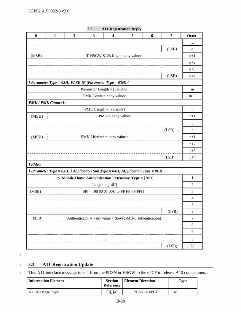
3GPP2 A.S0022-0 v2.0
B-28
3.2 A11-Registration Reply
0 1 2 3 4 5 6 7 Octet
…
(LSB) q
(MSB) T-HSGW S103 Key = <any value> q+1
q+2
q+3
(LSB) q+4
} Parameter Type = 02H; ELSE IF (Parameter Type = 03H) {
Parameter Length = [variable] m
PMK Count = <any value> m+1
PMK { PMK Count+1:
PMK Length = [variable] n
(MSB) PMK = <any value> n+1
…
(LSB) p
(MSB) PMK Lifetime = <any value> p+1
p+2
p+3
(LSB) p+4
} PMK;
} Parameter Type = 03H; } Application Sub Type = 04H; }Application Type = 0FH
Mobile-Home Authentication Extension: Type = [20H] 1
Length = [14H] 2
(MSB) SPI = [00 00 01 00H to FF FF FF FFH] 3
4
5
(LSB) 6
(MSB) Authenticator = <any value > (keyed-MD-5 authentication) 7
8
9
… …
(LSB) 22
1
3.3 A11-Registration Update 2
This A11 interface message is sent from the PDSN or HSGW to the ePCF to release A10 connections. 3
Information Element Section Reference
Element Direction Type
A11 Message Type [3], [4] PDSN -> ePCF M

3GPP2 A.S0022-0 v2.0
B-29
Information Element Section Reference
Element Direction Type
Reserved <3 octets> None PDSN -> ePCF Ma
Home Address [3], [4] PDSN -> ePCF M
Home Agent [3], [4] PDSN -> ePCF M
Identification [3], [4] PDSN -> ePCF M
Session Specific Extension [3], [4] PDSN -> ePCF Mc
Normal Vendor/Organization Specific Extension
4.2.14 PDSN -> ePCF Ob C
Registration Update Authentication Extension
[3], [4] PDSN -> ePCF M
a. This field is set to zero by the PDSN or HSGW and ignored by the ePCF. 1
b. This element is used by the PDSN or HSGW to provide a PDSN code to the ePCF. 2
c. For HRPD or eHRPD, the MN Session Reference Id field in this IE shall be set to 1. 3
The following table shows the bitmap layout for the A11-Registration Update message. 4
3.3 A11-Registration Update
0 1 2 3 4 5 6 7 Octet
Message Type = [14H] 1
Reserved = [00 00 00H] 1
2
3
(MSB) Home Address = [00 00 00 00H] 1
2
3
(LSB) 4
(MSB) Home Agent = <any value> 1
2
3
(LSB) 4
(MSB) Identification = <any value> 1
2
3
4
5
6
7
(LSB) 8
Session Specific Extension: Type = [27H] 1
Length = [13H – 15H] 2
(MSB) Protocol Type = [88 81H] 3
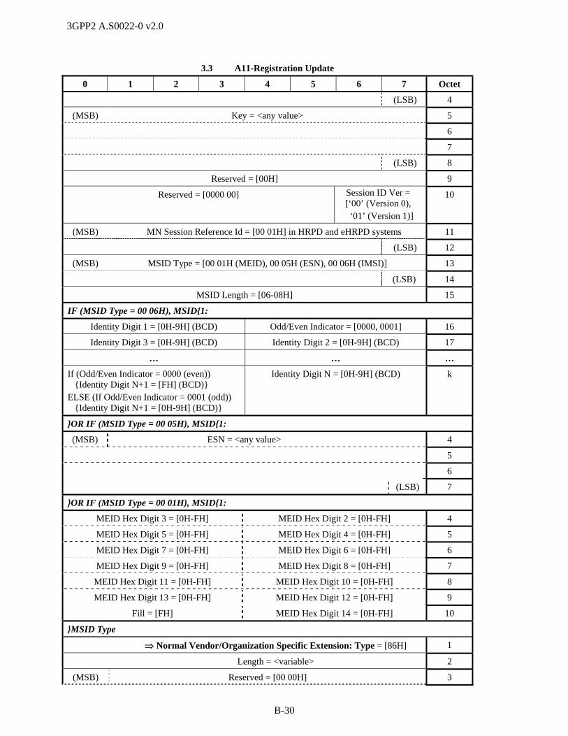
3GPP2 A.S0022-0 v2.0
B-30
3.3 A11-Registration Update
0 1 2 3 4 5 6 7 Octet
(LSB) 4
(MSB) Key = <any value> 5
6
7
(LSB) 8
Reserved = [00H] 9
Reserved = [0000 00] Session ID Ver = [‘00’ (Version 0), ‘01’ (Version 1)]
10
(MSB) MN Session Reference Id = [00 01H] in HRPD and eHRPD systems 11
(LSB) 12
(MSB) MSID Type = [00 01H (MEID), 00 05H (ESN), 00 06H (IMSI)] 13
(LSB) 14
MSID Length = [06-08H] 15
IF (MSID Type = 00 06H), MSID{1:
Identity Digit 1 = [0H-9H] (BCD) Odd/Even Indicator = [0000, 0001] 16
Identity Digit 3 = [0H-9H] (BCD) Identity Digit 2 = [0H-9H] (BCD) 17
… … …
If (Odd/Even Indicator = 0000 (even)) {Identity Digit N+1 = [FH] (BCD)} ELSE (If Odd/Even Indicator = 0001 (odd)) {Identity Digit N+1 = [0H-9H] (BCD)}
Identity Digit N = [0H-9H] (BCD) k
}OR IF (MSID Type = 00 05H), MSID{1:
(MSB) ESN = <any value> 4
5
6
(LSB) 7
}OR IF (MSID Type = 00 01H), MSID{1:
MEID Hex Digit 3 = [0H-FH] MEID Hex Digit 2 = [0H-FH] 4
MEID Hex Digit 5 = [0H-FH] MEID Hex Digit 4 = [0H-FH] 5
MEID Hex Digit 7 = [0H-FH] MEID Hex Digit 6 = [0H-FH] 6
MEID Hex Digit 9 = [0H-FH] MEID Hex Digit 8 = [0H-FH] 7
MEID Hex Digit 11 = [0H-FH] MEID Hex Digit 10 = [0H-FH] 8
MEID Hex Digit 13 = [0H-FH] MEID Hex Digit 12 = [0H-FH] 9
Fill = [FH] MEID Hex Digit 14 = [0H-FH] 10
}MSID Type
Normal Vendor/Organization Specific Extension: Type = [86H] 1
Length = <variable> 2
(MSB) Reserved = [00 00H] 3
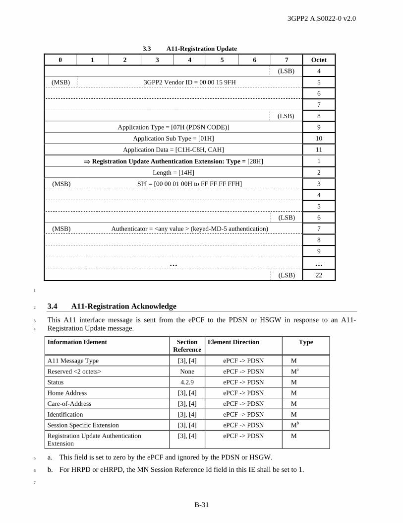
3GPP2 A.S0022-0 v2.0
B-31
3.3 A11-Registration Update
0 1 2 3 4 5 6 7 Octet
(LSB) 4
(MSB) 3GPP2 Vendor ID = 00 00 15 9FH 5
6
7
(LSB) 8
Application Type = [07H (PDSN CODE)] 9
Application Sub Type = [01H] 10
Application Data = [C1H-C8H, CAH] 11
Registration Update Authentication Extension: Type = [28H] 1
Length = [14H] 2
(MSB) SPI = [00 00 01 00H to FF FF FF FFH] 3
4
5
(LSB) 6
(MSB) Authenticator = <any value > (keyed-MD-5 authentication) 7
8
9
… …
(LSB) 22
1
3.4 A11-Registration Acknowledge 2
This A11 interface message is sent from the ePCF to the PDSN or HSGW in response to an A11-3
Registration Update message. 4
Information Element Section Reference
Element Direction Type
A11 Message Type [3], [4] ePCF -> PDSN M
Reserved <2 octets> None ePCF -> PDSN Ma
Status 4.2.9 ePCF -> PDSN M
Home Address [3], [4] ePCF -> PDSN M
Care-of-Address [3], [4] ePCF -> PDSN M
Identification [3], [4] ePCF -> PDSN M
Session Specific Extension [3], [4] ePCF -> PDSN Mb
Registration Update Authentication Extension
[3], [4] ePCF -> PDSN M
a. This field is set to zero by the ePCF and ignored by the PDSN or HSGW. 5
b. For HRPD or eHRPD, the MN Session Reference Id field in this IE shall be set to 1. 6
7
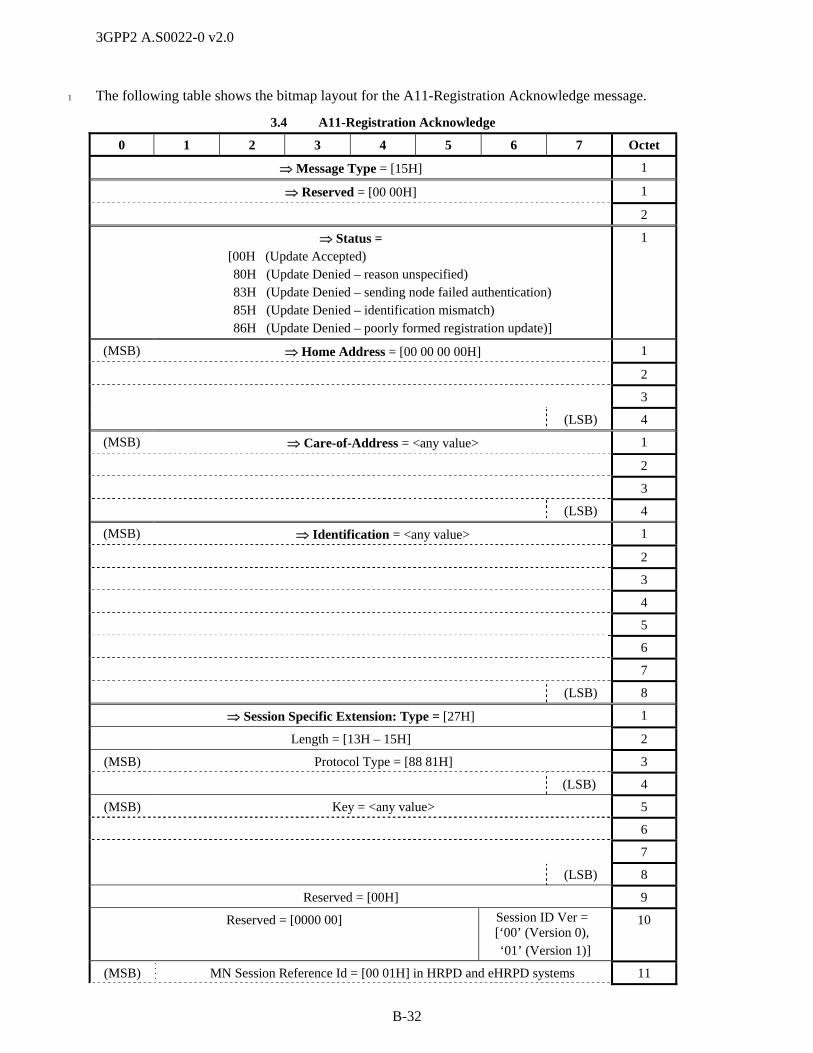
3GPP2 A.S0022-0 v2.0
B-32
The following table shows the bitmap layout for the A11-Registration Acknowledge message. 1
3.4 A11-Registration Acknowledge
0 1 2 3 4 5 6 7 Octet
Message Type = [15H] 1
Reserved = [00 00H] 1
2
Status = [00H (Update Accepted)
80H (Update Denied – reason unspecified) 83H (Update Denied – sending node failed authentication) 85H (Update Denied – identification mismatch) 86H (Update Denied – poorly formed registration update)]
1
(MSB) Home Address = [00 00 00 00H] 1
2
3
(LSB) 4
(MSB) Care-of-Address = <any value> 1
2
3
(LSB) 4
(MSB) Identification = <any value> 1
2
3
4
5
6
7
(LSB) 8
Session Specific Extension: Type = [27H] 1
Length = [13H – 15H] 2
(MSB) Protocol Type = [88 81H] 3
(LSB) 4
(MSB) Key = <any value> 5
6
7
(LSB) 8
Reserved = [00H] 9
Reserved = [0000 00] Session ID Ver = [‘00’ (Version 0), ‘01’ (Version 1)]
10
(MSB) MN Session Reference Id = [00 01H] in HRPD and eHRPD systems 11
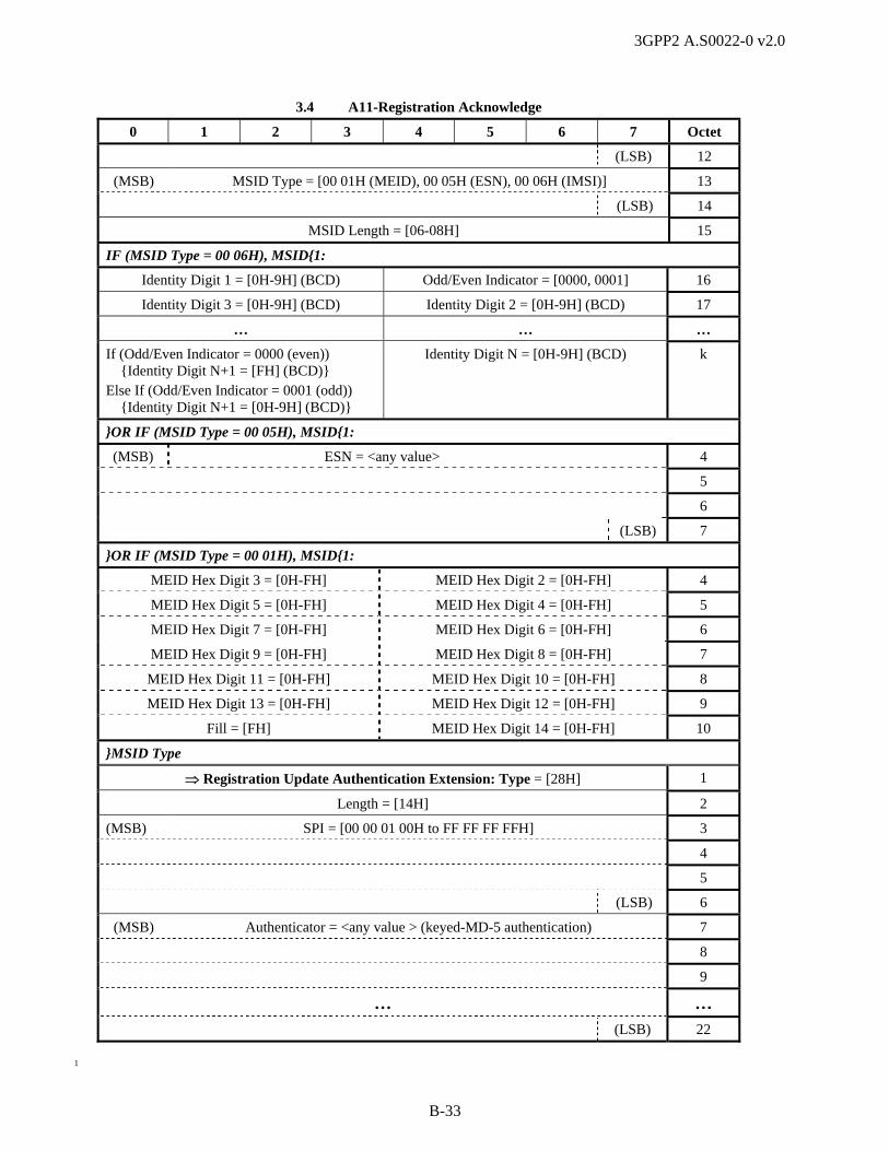
3GPP2 A.S0022-0 v2.0
B-33
3.4 A11-Registration Acknowledge
0 1 2 3 4 5 6 7 Octet
(LSB) 12
(MSB) MSID Type = [00 01H (MEID), 00 05H (ESN), 00 06H (IMSI)] 13
(LSB) 14
MSID Length = [06-08H] 15
IF (MSID Type = 00 06H), MSID{1:
Identity Digit 1 = [0H-9H] (BCD) Odd/Even Indicator = [0000, 0001] 16
Identity Digit 3 = [0H-9H] (BCD) Identity Digit 2 = [0H-9H] (BCD) 17
… … …
If (Odd/Even Indicator = 0000 (even)) {Identity Digit N+1 = [FH] (BCD)} Else If (Odd/Even Indicator = 0001 (odd)) {Identity Digit N+1 = [0H-9H] (BCD)}
Identity Digit N = [0H-9H] (BCD) k
}OR IF (MSID Type = 00 05H), MSID{1:
(MSB) ESN = <any value> 4
5
6
(LSB) 7
}OR IF (MSID Type = 00 01H), MSID{1:
MEID Hex Digit 3 = [0H-FH] MEID Hex Digit 2 = [0H-FH] 4
MEID Hex Digit 5 = [0H-FH] MEID Hex Digit 4 = [0H-FH] 5
MEID Hex Digit 7 = [0H-FH] MEID Hex Digit 6 = [0H-FH] 6
MEID Hex Digit 9 = [0H-FH] MEID Hex Digit 8 = [0H-FH] 7
MEID Hex Digit 11 = [0H-FH] MEID Hex Digit 10 = [0H-FH] 8
MEID Hex Digit 13 = [0H-FH] MEID Hex Digit 12 = [0H-FH] 9
Fill = [FH] MEID Hex Digit 14 = [0H-FH] 10
}MSID Type
Registration Update Authentication Extension: Type = [28H] 1
Length = [14H] 2
(MSB) SPI = [00 00 01 00H to FF FF FF FFH] 3
4
5
(LSB) 6
(MSB) Authenticator = <any value > (keyed-MD-5 authentication) 7
8
9
… …
(LSB) 22
1

3GPP2 A.S0022-0 v2.0
B-34
3.5 A11-Session Update 1
This A11 interface message is sent from the PDSN or HSGW to the ePCF to add new or update 2
parameters of an A10 connection. In 1x systems, it is also sent to update the ePCF with the Anchor P-P 3
Address. In HRPD or eHRPD systems with QoS, this message is sent to convey or update the subscriber 4
QoS profile after establishment of the main A10 connection. In HRPD or eHRPD systems with QoS, this 5
message may also be used for QoS update by the PDSN or HSGW. In eHRPD systems, this message may 6
also be used for sending PMK keys when they become available if they were unavailable when the ePCF 7
requested them. 8
Information Element Section Reference
Element Direction Type
A11 Message Type [3], [4] PDSN -> ePCF M
Reserved <3 octets> None PDSN -> ePCF Ma
Home Address [3], [4] PDSN -> ePCF M
Home Agent [3], [4] PDSN -> ePCF M
Identification [3], [4] PDSN -> ePCF M
Session Specific Extension [3], [4] PDSN -> ePCF Me
Normal Vendor/Organization Specific Extension
4.2.14 PDSN ->ePCF Ob,c,d,f,
g,h,i C
Registration Update Authentication Extension
[3], [4] PDSN -> ePCF M
9
a. This field is set to zero by the PDSN or HSGW and ignored by the ePCF. 10
b. In 1x systems, this element is used by the PDSN to provide an RN-PDIT value to the PCF. 11
c. When an Always-on Indicator is present at the PDSN, the PDSN shall include the NVSE with an 12
Always-on indicator 13
d. In 1x systems, this element is included by the PDSN to update the PCF with an Anchor P-P Address 14
for fast handoff. 15
e. For HRPD or eHRPD systems the MN Session Reference ID field of this IE shall be set to 00 01H. 16
f. In HRPD or eHRPD systems, this IE is used when the PDSN updates QoS or Flow Priority for one or 17
more IP flows in the specified direction. If there is a Flow Profile ID with the value ‘0x0000’ in the 18
U_QoS_SUB_BLOB for an IP flow, then the AN shall inform the AT that the requested 19
QoS_SUB_BLOB has been added but is invalid for this AN and the AT should not activate the 20
corresponding IP flow. Otherwise upon receipt of the updated QoS, the AN shall change the granted 21
QoS for the corresponding IP flow to the first acceptable Flow Profile ID in the list, irrespective of 22
the contents of the subscriber QoS Profile. A Flow Profile ID shall be considered acceptable if it is 23
supported by the AN, if it matches one of the Flow Profile IDs requested by the AT, and if the call is 24
not in inter-ePCF handoff. The target AN shall store the updated QoS lists received from the PDSN or 25
HSGW and use them to grant the QoS irrespective of the contents of the subscriber QoS Profile. 26
g. In HRPD or eHRPD systems, this IE is used to release for one or more IP flows in the specified 27
direction. The PDSN or HSGW shall set the FlowProfile ID value to ‘0x0000’ in the 28
Forward/Reverse Updated QoS Sub-BLOB for the IP flow to be released. The PDSN or HSGW 29
should not use this procedure for flow IDs FFH and FEH. 30
h. One or more instances of this element may be included. 31
i. In eHRPD systems, this IE is used to send PMK Information once it is available when the PMK 32
indication was included in an A11-Registration Request message for A10 establishment; however the 33

3GPP2 A.S0022-0 v2.0
B-35
PMK Information was unavailable at the time that the corresponding A11-Registration Reply 1
message was sent or if the PMK Indicator was included in an A11-Registration Request message for 2
A10 refresh. 3
The following table shows the bitmap layout for the A11-Session Update message. 4
3.5 A11-Session Update
0 1 2 3 4 5 6 7 Octet
Message Type = [16H] 1
(MSB) Reserved = [00 00 00H] 1
2
(LSB) 3
(MSB) Home Address = [00 00 00 00H] 1
2
3
(LSB) 4
(MSB) Home Agent = <any value> 1
2
3
(LSB) 4
(MSB) Identification = <any value> 1
2
3
4
5
6
7
(LSB) 8
Session Specific Extension: Type = [27H] 1
Length = [13H – 15H] 2
(MSB) Protocol Type = [88 81H] 3
(LSB) 4
(MSB) Key = <any value> 5
6
7
(LSB) 8
Reserved = [00H] 9
Reserved = [0000 00] Session ID Ver = [‘00’ (Version 0), ‘01’ (Version 1)]
10
(MSB) MN Session Reference Id = [00 01H] in HRPD or eHRPD systems 11
(LSB) 12

3GPP2 A.S0022-0 v2.0
B-36
3.5 A11-Session Update
0 1 2 3 4 5 6 7 Octet
(MSB) MSID Type = [00 01H (MEID), 00 05H (ESN), 00 06H (IMSI)] 13
(LSB) 14
MSID Length = [06-08H] 15
IF (MSID Type = 00 06H), MSID{1:
Identity Digit 1 = [0H-9H] (BCD) Odd/Even Indicator = [0000, 0001] 16
Identity Digit 3 = [0H-9H] (BCD) Identity Digit 2 = [0H-9H] (BCD) 17
… … …
If (Odd/Even Indicator = 0000 (even)) {Identity Digit N+1 = [FH] (BCD)} ELSE (If Odd/Even Indicator = 0001 (odd)) {Identity Digit N+1 = [0H-9H] (BCD)}
Identity Digit N = [0H-9H] (BCD) k
}OR IF (MSID Type = 00 05H), MSID{1:
(MSB) ESN = <any value> 4
5
6
(LSB) 7
}OR IF (MSID Type = 00 01H), MSID{1:
MEID Hex Digit 3 = [0H-FH] MEID Hex Digit 2 = [0H-FH] 4
MEID Hex Digit 5 = [0H-FH] MEID Hex Digit 4 = [0H-FH] 5
MEID Hex Digit 7 = [0H-FH] MEID Hex Digit 6 = [0H-FH] 6
MEID Hex Digit 9 = [0H-FH] MEID Hex Digit 8 = [0H-FH] 7
MEID Hex Digit 11 = [0H-FH] MEID Hex Digit 10 = [0H-FH] 8
MEID Hex Digit 13 = [0H-FH] MEID Hex Digit 12 = [0H-FH] 9
Fill = [FH] MEID Hex Digit 14 = [0H-FH] 10
}MSID Type
Normal Vendor/Organization Specific Extension: Type = [86H] 1
Length = <any value> 2
(MSB) Reserved = [00 00H] 3
(LSB) 4
(MSB) 3GPP2 Vendor ID = [00 00 15 9FH] 5
6
7
(LSB) 8
Application Type = 08H (Session Parameter), 0DH (QoS Information)] 9
IF (Application Type = 08H (Session Parameter)) {1:
Application Sub Type = [01H (RN-PDIT), 02H (Always-on)]] 10
ELSE IF (Application Type = 0DH (QoS Information)) {1:

3GPP2 A.S0022-0 v2.0
B-37
3.5 A11-Session Update
0 1 2 3 4 5 6 7 Octet
Application Sub Type = [03H (Subscriber QoS Profile), 04H (Forward Flow Priority Update Information), 05H (Reverse Flow Priority Update Information),
FEH (Forward QoS Update Information), FFH (Reverse QoS Update Information)]
10
IF (Application Sub Type = 03H (Subscriber QoS Profile)) {1
(MSB) Subscriber QoS Profile = <any value> 11
12
13
… …
(LSB) n
} Application Sub Type = 03H}; ELSE IF (Application Sub Type = 04H (Forward Flow Priority Update Information)) {1
Forward Flow Count = [01H - FFH] 11
Forward Flow Entry { Forward Flow Count :
Forward Flow ID = [00H - FFH] p
Reserved = [0000] Forward Updated Flow Priority = [0H – FH] p+1
} Application Sub Type = 04H}; ELSE IF (Application Sub Type = 05H (Reverse Flow PriorityUpdate Information)) {1
Reverse Flow Count = [01H - FFH] 11
Reverse Flow Entry { Reverse Flow Count :
Reverse Flow ID = [00H - FFH] p
Reserved = [0000] Reverse Updated Flow Priority = [0H – FH] p+1
} Application Sub Type = 05H}; ELSE IF (Application Sub Type = FEH (Forward QoS Update Information)) {1
Forward Flow Count = [01H - FFH] 11
Forward Flow Entry { Forward Flow Count :
Forward Flow ID = [00H - FFH] p
Forward Updated QoS Sub-BLOB Length = [variable] p+1
(MSB) Forward Updated QoS Sub-BLOB = <any value> p+2
… …
(LSB) q
} Forward Flow Entry
} Application Sub Type = FEH}; ELSE IF (Application Sub Type = FFH (Reverse QoS Update Information)) {1
Reverse Flow Count = [01H - FFH] 11
Reverse Flow Entry { Reverse Flow Count :
Reverse Flow ID = [00H - FFH] p
Reverse Updated QoS Sub-BLOB Length = [variable] p+1
(MSB) Reverse Updated QoS Sub-BLOB = <any value> p+2
… …

3GPP2 A.S0022-0 v2.0
B-38
3.5 A11-Session Update
0 1 2 3 4 5 6 7 Octet
(LSB) q
} Reverse Flow Entry
} Application Sub Type = FFH ;
} Application Type = 0DH; ELSE IF (Application Type = 0FH (Information)){1:
Application Sub Type = [04H (Additional HSGW Information)] 10
HSGW Parameter Entry {1:
Parameter Type = [03H] (PMK Information) m
Parameter Length = [variable] m+1
PMK Count = <any value> m+2
PMK { PMK Count+1:
PMK Length = [variable] n
(MSB) PMK = <any value> n+1
…
(LSB) p
(MSB) PMK Lifetime = <any value> p+1
p+2
p+3
(LSB) p+4
} PMK;
} Application Sub Type = 04H; }Application Type = 0FH;
Registration Update Authentication Extension: Type = [28H] 1
Length = [14H] 2
(MSB) SPI = [00 00 01 00H to FF FF FF FFH] 3
4
5
(LSB) 6
(MSB) Authenticator = <any value > (keyed-MD-5 authentication) 7
8
9
… …
(LSB) 22
1
3.6 A11-Session Update Acknowledge 2
This A11 interface message is sent from the ePCF to the PDSN or HSGW in response to an A11-Session 3
Update message. 4
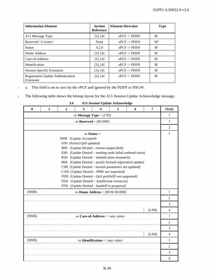
3GPP2 A.S0022-0 v2.0
B-39
Information Element Section Reference
Element Direction Type
A11 Message Type [3], [4] ePCF -> PDSN M
Reserved <2 octets> None ePCF -> PDSN Ma
Status 4.2.9 ePCF -> PDSN M
Home Address [3], [4] ePCF -> PDSN M
Care-of-Address [3], [4] ePCF -> PDSN M
Identification [3], [4] ePCF -> PDSN M
Session Specific Extension [3], [4] ePCF -> PDSN M
Registration Update Authentication Extension
[3], [4] ePCF -> PDSN M
a. This field is set to zero by the ePCF and ignored by the PDSN or HSGW. 1
The following table shows the bitmap layout for the A11-Session Update Acknowledge message. 2
3.6 A11-Session Update Acknowledge
0 1 2 3 4 5 6 7 Octet
Message Type = [17H] 1
Reserved = [00 00H] 1
2
Status = [00H (Update Accepted)
01H (Partial QoS updated) 80H (Update Denied – reason unspecified) 83H (Update Denied – sending node failed authentication) 85H (Update Denied – identification mismatch) 86H (Update Denied – poorly formed registration update) C9H (Update Denied – session parameters not updated) CAH (Update Denied – PMK not requested) FDH (Update Denied – QoS profileID not supported) FEH (Update Denied – insufficient resources) FFH (Update Denied – handoff in progress)]
1
(MSB) Home Address = [00 00 00 00H] 1
2
3
(LSB) 4
(MSB) Care-of-Address = <any value> 1
2
3
(LSB) 4
(MSB) Identification = <any value> 1
2
3
4

3GPP2 A.S0022-0 v2.0
B-40
3.6 A11-Session Update Acknowledge
0 1 2 3 4 5 6 7 Octet
5
6
7
(LSB) 8
Session Specific Extension: Type = [27H] 1
Length = [13H – 15H] 2
(MSB) Protocol Type = [88 81H] 3
(LSB) 4
(MSB) Key = <any value> 5
6
7
(LSB) 8
Reserved = [00H] 9
Reserved = [0000 00] Session ID Ver = [‘00’ (Version 0), ‘01’ (Version 1)]
10
(MSB) MN Session Reference Id = [00 01H] in HRPD or eHRPD systems 11
(LSB) 12
(MSB) MSID Type = [00 01H (MEID), 00 05H (ESN), 00 06H (IMSI)] 13
(LSB) 14
MSID Length = [06-08H] 15
IF (MSID Type = 00 06H), MSID{1:
Identity Digit 1 = [0H-9H] (BCD) Odd/Even Indicator = [0000, 0001] 16
Identity Digit 3 = [0H-9H] (BCD) Identity Digit 2 = [0H-9H] (BCD) 17
… … …
If (Odd/Even Indicator = 0000 (even)) {Identity Digit N+1 = [FH] (BCD)} Else If (Odd/Even Indicator = 0001 (odd)) {Identity Digit N+1 = [0H-9H] (BCD)}
Identity Digit N = [0H-9H] (BCD) k
}OR IF (MSID Type = 00 05H), MSID{1:
(MSB) ESN = <any value> 4
5
6
(LSB) 7
}OR IF (MSID Type = 00 01H), MSID{1:
MEID Hex Digit 3 = [0H-FH] MEID Hex Digit 2 = [0H-FH] 4
MEID Hex Digit 5 = [0H-FH] MEID Hex Digit 4 = [0H-FH] 5
MEID Hex Digit 7 = [0H-FH] MEID Hex Digit 6 = [0H-FH] 6
MEID Hex Digit 9 = [0H-FH] MEID Hex Digit 8 = [0H-FH] 7
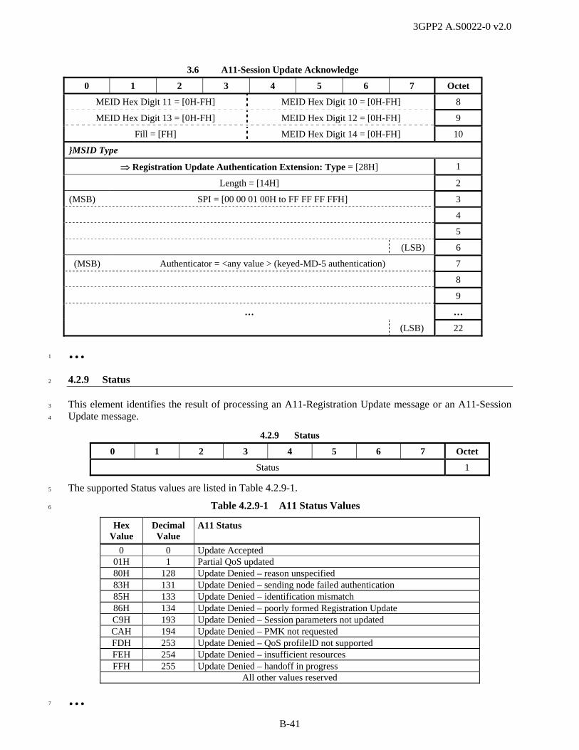
3GPP2 A.S0022-0 v2.0
B-41
3.6 A11-Session Update Acknowledge
0 1 2 3 4 5 6 7 Octet
MEID Hex Digit 11 = [0H-FH] MEID Hex Digit 10 = [0H-FH] 8
MEID Hex Digit 13 = [0H-FH] MEID Hex Digit 12 = [0H-FH] 9
Fill = [FH] MEID Hex Digit 14 = [0H-FH] 10
}MSID Type
Registration Update Authentication Extension: Type = [28H] 1
Length = [14H] 2
(MSB) SPI = [00 00 01 00H to FF FF FF FFH] 3
4
5
(LSB) 6
(MSB) Authenticator = <any value > (keyed-MD-5 authentication) 7
8
9
… …
(LSB) 22
… 1
4.2.9 Status 2
This element identifies the result of processing an A11-Registration Update message or an A11-Session 3
Update message. 4
4.2.9 Status
0 1 2 3 4 5 6 7 Octet
Status 1
The supported Status values are listed in Table 4.2.9-1. 5
Table 4.2.9-1 A11 Status Values 6
Hex Value
Decimal Value
A11 Status
0 0 Update Accepted 01H 1 Partial QoS updated 80H 128 Update Denied – reason unspecified 83H 131 Update Denied – sending node failed authentication 85H 133 Update Denied – identification mismatch 86H 134 Update Denied – poorly formed Registration Update C9H 193 Update Denied – Session parameters not updated CAH 194 Update Denied – PMK not requested FDH 253 Update Denied – QoS profileID not supported FEH 254 Update Denied – insufficient resources FFH 255 Update Denied – handoff in progress
All other values reserved
… 7

3GPP2 A.S0022-0 v2.0
B-42
4.2.14 Normal Vendor/Organization Specific Extension (NVSE) 1
This element may be included in the A11-Registration Request, A11-Registration Reply, A11-2
Registration Update, and A11-Session Update messages to convey information between the ePCF and the 3
PDSN. Any new Application Types or Application Sub-Types supported after IOS v4.0 shall be added to 4
this element. The coding format of the NVSE defined herein conforms to RFC 3115 [30]. 5
For 1x, HRPD and eHRPD, this element may be included in the A11-Registration Request message to 6
convey the PANID and CANID to the PDSN or HSGW. If ANID is sent to the HSGW, it shall be 7
ignored. 8
For 1x, this element may be included in A11-Registration Reply, A11-Registration Request, or A11-9
Session Update messages to convey the Anchor PDSN Address for fast handoff when the ePCF 10
establishes an A10 connection. When sent by the PCF, the Anchor P-P Address is the address received in 11
the fast handoff request from the source BS/PCF. When sent by the PDSN, the Anchor P-P Address value 12
is copied from the corresponding A11-Registration Request if the PDSN accepts a fast handoff request. It 13
is the PDSN’s own P-P address if the PDSN supports fast handoff and becomes the anchor PDSN. 14
If the receiver does not recognize the NVSE Vendor-ID or the NVSE Application Type or Application 15
Sub Type, it shall ignore the NVSE and process the remainder of the message to the extent possible. 16
For 1x, this element may be included in the A11-Registration Request message to send the All Dormant 17
Indicator for the case of an MS in fast handoff. The serving ePCF shall send the All Dormant Indicator to 18
its supporting PDSN when all service instances for the MS become dormant. The ePCF shall send this 19
indication in the same message as the Active Stop Airlink Record for the last service instance that 20
becomes dormant. 21
This element may be included in the A11-Registration Update message to indicate the reason the PDSN 22
initiated the release of the packet data session. 23
This element may be included in the A11-Registration Reply or A11-Session Update messages to change 24
the value of a session parameter. 25
This element may be included in the A11-Registration Request message to indicate the service option of a 26
service instance. For HRPD and eHRPD, this is the service option of the main service instance. 27
For 1x, this element may be included in the A11-Session Update message to indicate a PDSN Identifier. 28
This element may be included in the A11-Registration Request message to indicate the features enables 29
by the ePCF. 30
This element may be included in the A11-Registration Reply message to indicate the features enabled by 31
the PDSN. 32
For HRPD and eHRPD, this IE may be included in the A11-Registration Request message to indicate SO, 33
SR_ID, Key, Protocol Type for auxiliary A10 connection(s). 34
For HRPD and eHRPD, this IE may be included in the A11-Registration Reply message to indicate 35
SR_ID and Key for auxiliary A10 connection(s). 36
For HRPD and eHRPD, this IE may be included in the A11-Registration Request message to convey QoS 37
information (IP Flow ID, Flow State, Requested QoS, and Granted QoS). Each instance of the NVSE IE 38
with QoS Information application type contains QoS information for IP flows associated with one 39
direction of one A10 connection. For transmission of QoS Information in both directions of an A10 40
connection or for multiple A10 connections (i.e., multiple SR_IDs) in the same A11-Registration 41
Request, multiple instances of the QoS Information application type NVSE are used. 42
For HRPD and eHRPD, this IE may be included in the A11-Session Update message to convey updated 43
QoS information or updated Flow Priority information. 44
For eHRPD, the ePCF shall include this IE with Application Type 06H, Application Sub Type 02H 45
(eHRPD Mode indication) when establishing the main A10 connection if the HSGW A11 IP address is 46

3GPP2 A.S0022-0 v2.0
B-43
shared with PDSN. The ePCF should not include the eHRPD Mode indication when establishing the main 1
A10 connection if the HSGW A11 IP address is not shared with PDSN. If the ePCF includes an eHRPD 2
Mode indication in an A11-Registration Request message, the HSGW should ignore it. 3
For eHRPD, this IE shall be included in the A11-Registration Request message with Application Type 4
06H, Application Sub Type 03H (eHRPD Indicators) if the eAT is operating in evolved mode and the 5
eHRPD system supports optimized mobility between eHRPD and E-UTRAN. The ePCF shall not include 6
eHRPD Indicators if the mobile is operating in legacy mode. The E-UTRAN Handoff Info indication is 7
set to ‘1’ if the sender is requesting information needed for handoff to E-UTRAN. 8
For eHRPD, this IE shall be included in the A11-Registration Reply message with Application Type 0FH 9
(Information), Application Sub Type 02H (HSGW H1 Address Information) to convey the HSGW’s H1 10
IPv4 address when the ePCF establishes the main A10 connection. 11
For eHRPD, the target PCF shall include this IE in the A11-Registration Request message with 12
Application Type 0FH (Information), Application Sub Type 02H (HSGW H1 Address Information) when 13
this message is sent for inter-HSGW handoff to convey the source HSGW’s H1 IPv4 address received 14
from the source PCF. 15
For eHRPD, this IE may be included in the A11-Registration Reply message with Application Type 0FH 16
(Information), Application Sub Type 03H (EPS Information), Parameter Types 01H (APN Information), 17
02H (S103 Source GRE Key Information) and 03H (P-GW IP Address) to send information needed for 18
handoff from eHRPD to E-UTRAN in response to a request for this information. 19
For handoff, this IE may be included in the A11-Registration Request message with Application Type 20
0FH (Information), Application Sub Type 03H (EPS Information), Parameter Types 01H (APN 21
Information), 02H (S103 Source GRE Key Information) and 03H (P-GW IP Address) in preparation for 22
handoff from E-UTRAN to eHRPD. 23
For eHRPD, this IE may be included in the A11-Registration Reply message with Application Type 0FH 24
(Information), Application Sub Type 04H (Additional HSGW Information), Parameter Types 01H (T-25
HSGW S103 IP Address) and 02H (T-HSGW S103 Key) to send the Target HSGW Address Information 26
in preparation for handoff from E-UTRAN to eHRPD. Multiple instances of Parameter Type 02H may be 27
included. 28
For eHRPD, this IE may be included in the A11-Registration Request message to indicate that the 29
eHRPD RAN is capable of GKE and to request PMK information. 30
For eHRPD, this IE may be included in the A11-Registration Reply or A11-Session Update Request 31
message with Application Type 0FH (Information), Application Sub Type 04H (Additional HSGW 32
Information), Parameter Type 03H (PMK Information) to send PMK Information in support of GKE 33
operation. 34
35
4.2.14 Normal Vendor/Organization Specific Extension (NVSE)
0 1 2 3 4 5 6 7 Octet
A11 Element Identifier (Type) 1
Length 2
(MSB) Reserved 3
(LSB) 4
(MSB) 3GPP2 Vendor ID 5
6
7
(LSB) 8
Application Type 9
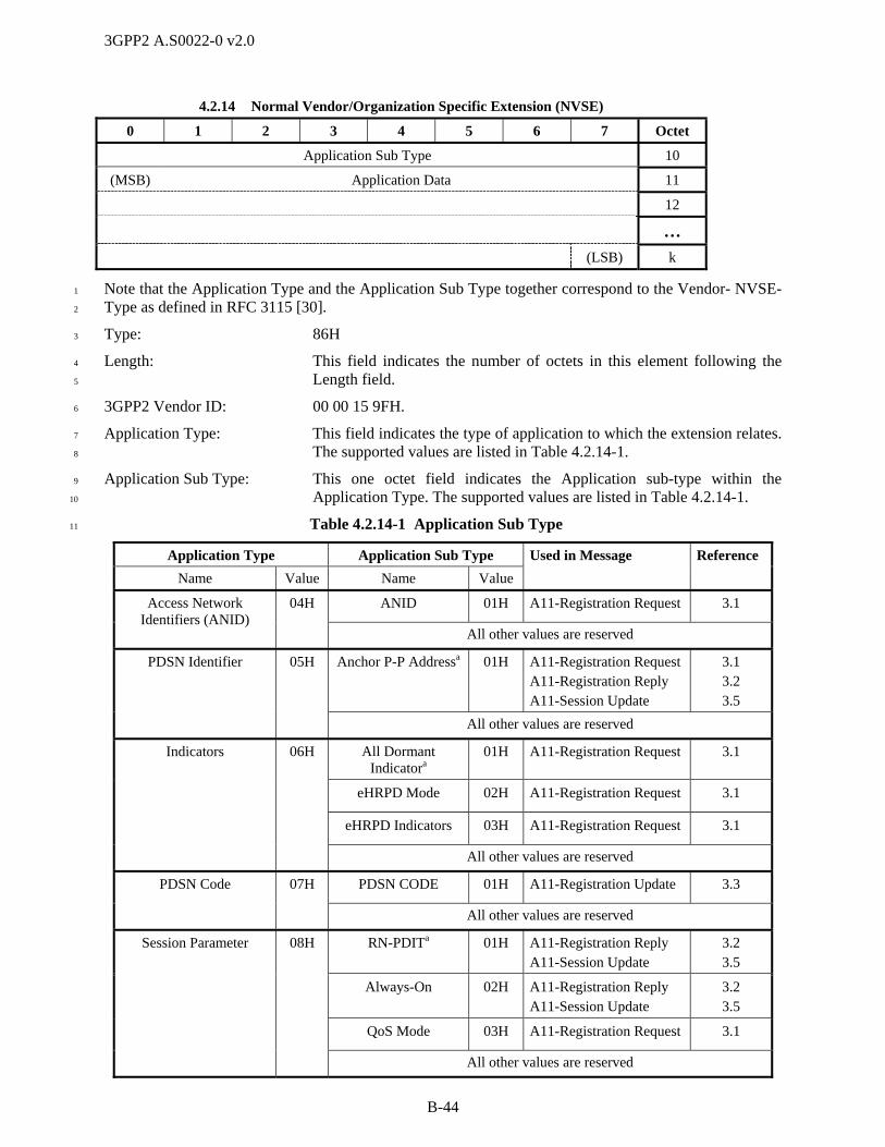
3GPP2 A.S0022-0 v2.0
B-44
4.2.14 Normal Vendor/Organization Specific Extension (NVSE)
0 1 2 3 4 5 6 7 Octet
Application Sub Type 10
(MSB) Application Data 11
12
…
(LSB) k
Note that the Application Type and the Application Sub Type together correspond to the Vendor- NVSE-1
Type as defined in RFC 3115 [30]. 2
Type: 86H 3
Length: This field indicates the number of octets in this element following the 4
Length field. 5
3GPP2 Vendor ID: 00 00 15 9FH. 6
Application Type: This field indicates the type of application to which the extension relates. 7
The supported values are listed in Table 4.2.14-1. 8
Application Sub Type: This one octet field indicates the Application sub-type within the 9
Application Type. The supported values are listed in Table 4.2.14-1. 10
Table 4.2.14-1 Application Sub Type 11
Application Type Application Sub Type
Name Value Name Value
Used in Message Reference
ANID 01H A11-Registration Request 3.1 Access Network Identifiers (ANID)
04H
All other values are reserved
Anchor P-P Addressa 01H A11-Registration Request A11-Registration Reply A11-Session Update
3.1 3.2 3.5
PDSN Identifier 05H
All other values are reserved
All Dormant Indicatora
01H A11-Registration Request 3.1
eHRPD Mode 02H A11-Registration Request 3.1
eHRPD Indicators 03H A11-Registration Request 3.1
Indicators 06H
All other values are reserved
PDSN CODE 01H A11-Registration Update 3.3 PDSN Code 07H
All other values are reserved
RN-PDITa 01H A11-Registration Reply A11-Session Update
3.2 3.5
Always-On 02H A11-Registration Reply A11-Session Update
3.2 3.5
QoS Mode 03H A11-Registration Request 3.1
Session Parameter 08H
All other values are reserved

3GPP2 A.S0022-0 v2.0
B-45
Application Type Application Sub Type
Name Value Name Value
Used in Message Reference
Service Option Value 01H A11-Registration Request 3.1 Service Option 09H
All other values are reserved
Flow Control Enabled
01H A11-Registration Reply 3.2
Packet Boundary Enabled
02H A11-Registration Reply 3.2
GRE Segmentation Enabled
03H A11-Registration Reply 3.2
PDSN Enabled Features 0AH
All other values are reserved
Short Data Indication Supported
01H A11-Registration Request 3.1
GRE Segmentation Enabled
02H A11-Registration Request 3.1
PCF Enabled Features 0BH
All other values are reserved
Additional Session Information
01H A11-Registration Request A11-Registration Reply
3.1 3.2
Additional Session Information
0CH
All other values are reserved
Forward QoS Information
01H A11-Registration Request 3.1
Reverse QoS Information
02H A11-Registration Request 3.1
Subscriber QoS Profile
03H A11-Registration Reply A11-Session Update
3.2 3.5
Forward Flow Priority Update
Information
04H A11-Session Update 3.5
Reverse Flow Priority Update Information
05H A11-Session Update 3.5
Forward QoS Update Information
FEH A11-Session Update 3.5
Reverse QoS Update Information
FFH A11-Session Update 3.5
QoS Information 0DH
All other values are reserved
ROHC Configuration Parameters
01H A11-Registration Reply 3.2 Header Compression 0EH
All other values are reserved
Cause Code 01H A11-Registration Request 3.1
HSGW H1 Address Information
02H A11-Registration Request A11-Registration Reply
3.1 3.2
Information 0FH
EPS Information 03H A11-Registration Request A11-Registration Reply
3.1 3.2
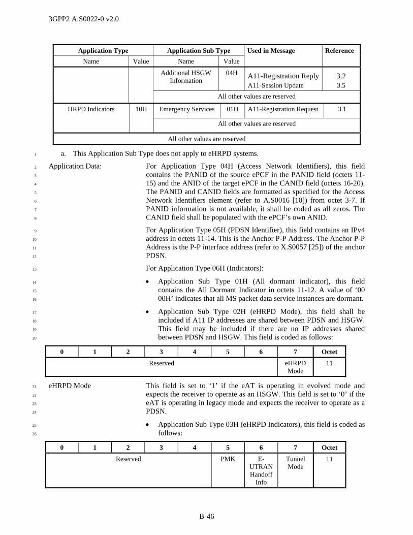
3GPP2 A.S0022-0 v2.0
B-46
Application Type Application Sub Type
Name Value Name Value
Used in Message Reference
Additional HSGW Information
04H A11-Registration Reply A11-Session Update
3.2 3.5
All other values are reserved
Emergency Services 01H A11-Registration Request 3.1 HRPD Indicators 10H
All other values are reserved
All other values are reserved
a. This Application Sub Type does not apply to eHRPD systems. 1
Application Data: For Application Type 04H (Access Network Identifiers), this field 2
contains the PANID of the source ePCF in the PANID field (octets 11-3
15) and the ANID of the target ePCF in the CANID field (octets 16-20). 4
The PANID and CANID fields are formatted as specified for the Access 5
Network Identifiers element (refer to A.S0016 [10]) from octet 3-7. If 6
PANID information is not available, it shall be coded as all zeros. The 7
CANID field shall be populated with the ePCF’s own ANID. 8
For Application Type 05H (PDSN Identifier), this field contains an IPv4 9
address in octets 11-14. This is the Anchor P-P Address. The Anchor P-P 10
Address is the P-P interface address (refer to X.S0057 [25]) of the anchor 11
PDSN. 12
For Application Type 06H (Indicators): 13
Application Sub Type 01H (All dormant indicator), this field 14
contains the All Dormant Indicator in octets 11-12. A value of ‘00 15
00H’ indicates that all MS packet data service instances are dormant. 16
Application Sub Type 02H (eHRPD Mode), this field shall be 17
included if A11 IP addresses are shared between PDSN and HSGW. 18
This field may be included if there are no IP addresses shared 19
between PDSN and HSGW. This field is coded as follows: 20
0 1 2 3 4 5 6 7 Octet
Reserved eHRPD Mode
11
eHRPD Mode This field is set to ‘1’ if the eAT is operating in evolved mode and 21
expects the receiver to operate as an HSGW. This field is set to ‘0’ if the 22
eAT is operating in legacy mode and expects the receiver to operate as a 23
PDSN. 24
Application Sub Type 03H (eHRPD Indicators), this field is coded as 25
follows: 26
0 1 2 3 4 5 6 7 Octet
Reserved PMK E-UTRAN Handoff
Info
Tunnel Mode
11
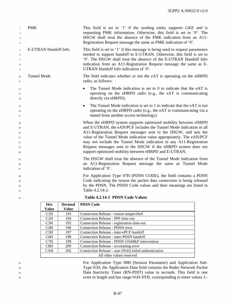
3GPP2 A.S0022-0 v2.0
B-47
PMK This field is set to ‘1’ if the sending entity supports GKE and is 1
requesting PMK information. Otherwise, this field is set to ‘0’. The 2
HSGW shall treat the absence of the PMK indication from an A11-3
Registration Request message the same as PMK indication of ‘0’. 4
E-UTRAN Handoff Info This field is set to ‘1’ if this message is being used to request parameters 5
needed to support handoff to E-UTRAN. Otherwise, this field is set to 6
‘0’. The HSGW shall treat the absence of the E-UTRAN Handoff Info 7
indication from an A11-Registration Request message the same as E-8
UTRAN Handoff Info indication of ‘0’. 9
Tunnel Mode The field indicates whether or not the eAT is operating on the eHRPD 10
radio, as follows: 11
The Tunnel Mode indication is set to 0 to indicate that the eAT is 12
operating on the eHRPD radio (e.g., the eAT is communicating 13
directly via eHRPD). 14
The Tunnel Mode indication is set to 1 to indicate that the eAT is not 15
operating on the eHRPD radio (e.g., the eAT is communicating via a 16
tunnel from another access technology). 17
When the eHRPD system supports optimized mobility between eHRPD 18
and E-UTRAN, the eAN/PCF includes the Tunnel Mode indication in all 19
A11-Registration Request messages sent to the HSGW, and sets the 20
value of the Tunnel Mode indication value appropriately. The eAN/PCF 21
may not include the Tunnel Mode indication in any A11-Registration 22
Request messages sent to the HSGW if the eHRPD system does not 23
support optimized mobility between eHRPD and E-UTRAN. 24
The HSGW shall treat the absence of the Tunnel Mode indication from 25
an A11-Registration Request message the same as Tunnel Mode 26
indication of ‘0’. 27
For Application Type 07H (PDSN CODE), the field contains a PDSN 28
Code indicating the reason the packet data connection is being released 29
by the PDSN. The PDSN Code values and their meanings are listed in 30
Table 4.2.14-2. 31
Table 4.2.14-2 PDSN Code Values 32
Hex Value
Decimal Value
PDSN Code
C1H 193 Connection Release - reason unspecified C2H 194 Connection Release - PPP time-out C3H 195 Connection Release - registration time-out C4H 196 Connection Release - PDSN error C5H 197 Connection Release - inter-ePCF handoff C6H 198 Connection Release - inter-PDSN handoff C7H 199 Connection Release - PDSN OAM&P intervention C8H 200 Connection Release - accounting error CAH 202 Connection Release - user (NAI) failed authentication
All other values reserved
For Application Type 08H (Session Parameter) and Application Sub-33
Type 01H, the Application Data field contains the Radio Network Packet 34
Data Inactivity Timer (RN-PDIT) value in seconds. This field is one 35
octet in length and has range 01H–FFH, corresponding to timer values 1–36

3GPP2 A.S0022-0 v2.0
B-48
255 seconds. For Application Sub Type 02H (Always-on indicator), the 1
Application Data is zero bytes in length. 2
For Application Type 08H (Session Parameter) and Application Sub-3
Type 03H (QoS Mode), the Application data field is one octet in length 4
and indicates whether IP flow based QoS is available for the current 5
personality of the AT. The application data field is coded as follows: 6
7
0 1 2 3 4 5 6 7 Octet
(MSB) QoS Mode (LSB) 1
QoS Mode: 8
Table 4.2.14-3 QoS Mode Values 9
QoS Mode Description
00H The AT and the AN apply air interface protocol that IP flow based QoS is unavailable.
01H The AT and the AN apply air interface protocol that IP flow based QoS is available.
10
For Application Type 09H (Service Option), this field contains the 11
Service Option value for the service instance associated with the A10 12
connection for 1x. It contains the Service Option value for the main 13
service connection for HRPD and eHRPD. 14
For Application Type 09H, the Application Data field is coded as follows: 15
0 1 2 3 4 5 6 7 Octet
(MSB) Service Option 1
(LSB) 2
Service Option: 16
Table 4.2.14-4 1x Service Option Values 17
Service Option Value (hex)
Description
0021H 3G High Speed Packet Data
003CH Link Layer Assisted Header Removal
003DH Link Layer Assisted RObust Header Compression
Table 4.2.14-5 HRPD and eHRPD Service Option Values 18
Service Option Value (hex)
Description
003BH HRPD Main Service Instance
19
For Application Type 0AH (PDSN Enabled Features) and Application 20
Sub-Type 01H (Flow Control Enabled), the Application Data field is 21

3GPP2 A.S0022-0 v2.0
B-49
zero bytes in length. This Application Sub-Type is included if the PDSN 1
enables flow control for the corresponding A10 connection. 2
For Application Type 0AH (PDSN Enabled Features) and Application 3
Sub-Type 02H (Packet Boundary Enabled), the Application Data field is 4
zero bytes in length. This Application Sub-Type is included if the PDSN 5
guarantees packet boundaries either by encapsulating one packet in one 6
GRE frame or by supplying GRE segmentation indication in the GRE 7
frame (if supported by the RAN) for the corresponding A10 connection. 8
For Application Type 0AH (PDSN Enabled Features) and Application 9
Sub-Type 03H (GRE Segmentation Enabled), the Application Data field 10
is zero bytes in length. This Application Sub-Type shall be included if 11
the PDSN is capable of receiving the GRE segmentation attribute in the 12
GRE header for the corresponding A10 connection, for packets 13
fragmented over one or more GRE frames. 14
For Application Type 0BH (ePCF Enabled Features) and Application 15
Sub-Type 01H (Short Data Indication Supported), the Application Data 16
field is zero bytes in length. This Application Sub-Type is included by 17
the ePCF in the A11-Registration Request message to request Short Data 18
Indications via the GRE header. 19
For Application Type 0BH (ePCF Enabled Features) and Application 20
Sub-Type 02H (GRE Segmentation Enabled), the Application Data field 21
is zero bytes in length. This Application Sub-Type shall be included if 22
the ePCF is capable of receiving the GRE segmentation attribute in the 23
GRE header for the corresponding A10 connection, for packets 24
fragmented over one or more GRE frames. 25
For Application Type 0CH (Additional Session Information), Application Sub Type 01H (Additional 26
Session Information), the Application Data field is coded as follows: 27
0 1 2 3 4 5 6 7 Octet
GRE Key Information Entry { 1-30:
Entry Length 1
SR_ID = [00H-1FH] 2
(MSB) Service Option 3
(LSB) 4
(MSB) Protocol Type 5
(LSB) 6
(MSB) Key 7
8
9
(LSB) 10
(MSB) Source IP Address 11
12
13
(LSB) 14
Forward ROHC Info{0 (if sent by PDSN), 1 (if sent by ePCF):
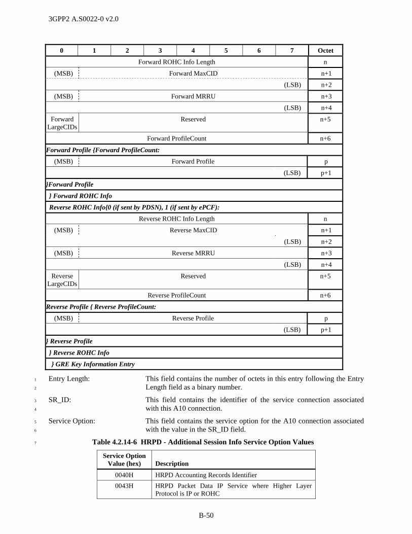
3GPP2 A.S0022-0 v2.0
B-50
0 1 2 3 4 5 6 7 Octet
Forward ROHC Info Length n
(MSB) Forward MaxCID n+1
(LSB) n+2
(MSB) Forward MRRU n+3
(LSB) n+4
Forward LargeCIDs
Reserved n+5
Forward ProfileCount n+6
Forward Profile {Forward ProfileCount:
(MSB) Forward Profile p
(LSB) p+1
}Forward Profile
} Forward ROHC Info
Reverse ROHC Info{0 (if sent by PDSN), 1 (if sent by ePCF):
Reverse ROHC Info Length n
(MSB) Reverse MaxCID n+1
(LSB) n+2
(MSB) Reverse MRRU n+3
(LSB) n+4
Reverse LargeCIDs
Reserved n+5
Reverse ProfileCount n+6
Reverse Profile { Reverse ProfileCount:
(MSB) Reverse Profile p
(LSB) p+1
} Reverse Profile
} Reverse ROHC Info
} GRE Key Information Entry
Entry Length: This field contains the number of octets in this entry following the Entry 1
Length field as a binary number. 2
SR_ID: This field contains the identifier of the service connection associated 3
with this A10 connection. 4
Service Option: This field contains the service option for the A10 connection associated 5
with the value in the SR_ID field. 6
Table 4.2.14-6 HRPD - Additional Session Info Service Option Values 7
Service Option Value (hex)
Description
0040H HRPD Accounting Records Identifier
0043H HRPD Packet Data IP Service where Higher Layer Protocol is IP or ROHC

3GPP2 A.S0022-0 v2.0
B-51
Table 4.2.14-7 eHRPD – Additional Session Info Service Option Values 1
Service Option Value (hex)
Description
0040H HRPD Accounting Records Identifier
0043H HRPD Packet Data IP Service where Higher Layer Protocol is IP or ROHC
0048H HRPD auxiliary Packet Data IP Service with PDN multiplexing header
2
Protocol Type: This field is used to indicate the protocol type to be tunneled across the 3
A10 interface, and contains the same value that is used in the Protocol 4
Type field in the GRE header on the associated A10 connection when the 5
packet doesn’t include GRE attributes. This field is set to 0x88 81H 6
(Unstructured Byte Stream). 7
Key: This is a four octet field. This field is used to indicate the A10 8
connection identification, and contains the same value that is used in the 9
Key field in the GRE header on the associated A10 connection. 10
Source IP Address: This field identifies the IPv4 address of the ePCF that terminates the A10 11
connection identified in this entry. Note that this address may be 12
different from the source IP address of other A10 connections (including 13
the main A10 connection) and different from the source IP address of the 14
message containing this IE. 15
The remaining fields in this application type only apply in the ePCF to PDSN direction and are omitted 16
when this NVSE is sent from the PDSN to the ePCF. 17
Forward ROHC Info Length: This field is used to indicate whether to create a forward ROHC channel 18
on the A10 connection being created. If the Service Option for this entry 19
is 43H and this A10 connection has a forward ROHC channel 20
(compressor at PDSN, decompressor at AT), then this field indicates the 21
number of octets following this field that carry ROHC configuration 22
parameters (Forward MaxCID, Forward MRRU, Forward LargeCIDs, 23
Forward ProfileCount, and Forward Profile fields). Otherwise it is set to 24
‘0’. 25
Forward MaxCID: This field contains the MAX_CID parameter for this ROHC channel as 26
defined in RFC 3095 [29]. 27
Forward MRRU: This field contains the MRRU parameter for this ROHC channel as 28
defined in RFC 3095 [29]. 29
Forward LargeCIDs: This field contains the LARGE_CIDS parameter for this ROHC channel 30
as defined in RFC 3095 [29]. 31
Forward ProfileCount: This field contains the number of ROHC Profiles supported by the 32
decompressor, which corresponds to the number of Profiles contained in 33
this IE, as a binary number. 34
Forward Profile: This field indicates a ROHC profile supported by the decompressor 35
IANA ROHC profile identifier definitions can be found at Internet 36
Assigned Numbers Authority [31]. 37
Reverse ROHC Info Length: This field is used to indicate whether to create a reverse ROHC channel 38
on the A10 connection being created. If the Service Option for this entry 39
is 43H and this A10 connection has a reverse ROHC channel 40

3GPP2 A.S0022-0 v2.0
B-52
(compressor at AT, decompressor at PDSN), then this field indicates the 1
number of octets following this field that carry ROHC configuration 2
parameters (Reverse MaxCID, Reverse MRRU, Reverse LargeCIDs, 3
Reverse ProfileCount, and Reverse Profile fields). Otherwise it is set to 4
‘0’. 5
Reverse MaxCID: This field contains the MAX_CID parameter for this ROHC channel as 6
defined in RFC 3095 [29]. 7
Reverse MRRU: This field contains the MRRU parameter for this ROHC channel as 8
defined in RFC 3095 [29]. 9
Reverse LargeCIDs: This field contains the LARGE_CIDS parameter for this ROHC channel 10
as defined in RFC 3095 [29]. 11
Reverse ProfileCount: This field contains the number of ROHC Profiles supported by the 12
decompressor, which corresponds to the number of Profiles contained in 13
this IE, as a binary number. 14
Reverse Profile: This field indicates a ROHC profile supported by the decompressor 15
IANA ROHC profile identifier definitions can be found at Internet 16
Assigned Numbers Authority [31]. 17
For Application Type 0DH (QoS Information) and Application Sub-Type 18
01H (Forward QoS Information), the Application Data field specifies all 19
of the forward IP flow(s) that are associated with a given service 20
connection. It is coded as follows. 21
0 1 2 3 4 5 6 7 Octet
SR_ID = [00H-1FH] 11
Use IP Flow
Discrimi-nation
DSCP Included
Reserved 12
Reserved Forward Flow Count 13
Forward Flow Entry {Forward Flow Count :
Entry Length n
Forward Flow ID n+1
Reserved DSCP Flow State
n+2
Forward Requested QoS Length n+3
(MSB) Forward Requested QoS n+4
… …
(LSB) p
Forward Granted QoS Length p+1
(MSB) Forward Granted QoS p+2
… …
(LSB) q
}Forward Flow Entry
22

3GPP2 A.S0022-0 v2.0
B-53
Length: This field indicates the number of octets in this element 1
following the Length field. 2
SR_ID: This field identifies the service connection. 3
Use IP Flow Discrimination: This field indicates if the PDSN shall include GRE extension for 4
IP flow discrimination. If this field is set to '0', the PDSN shall 5
not include the GRE extension for IP flow discrimination in the 6
bearer packets for the A10 connection identified in the SR_ID 7
field of this Forward Flow Entry. Otherwise (set to '1') it 8
indicates that the GRE extension for IP flow discrimination shall 9
be included. 10
DSCP Included: This field indicates whether DSCP values are included in this IE. 11
If option 1c in section 2.6.2 of the transport document is used, 12
then the value shall be set to ‘1’. Otherwise, the value shall be 13
set to ‘0’ and all DSCP fields in this IE shall be ignored. 14
Forward Flow Count: This field indicates the number of Flow ID Entry contained in 15
this Forward QoS Information Entry. 16
Entry Length: This field contains the number of octets in this entry following 17
the Entry Length field as a binary number. 18
Forward Flow ID: This field contains the flow ID of a given forward IP flow. Refer 19
to X.S0057 [25] for detailed information. 20
DSCP: If DSCP Included = ‘1’, then this field contains the DSCP value 21
of the flow identified in the corresponding Forward Flow ID 22
field. Otherwise, this field shall be set to ‘00 0000’ and shall be 23
ignored. 24
Flow State: This field indicates the IP flow state of the flow identified in the 25
corresponding Flow ID field. This field is set to '0' if it is 26
deactivated. This field is set to '1' if it is activated. 27
Forward Requested QoS Length: This field contains the number of octets in the Forward 28
Requested QoS field as a binary number. This field is set to zero 29
if the IP flow has no Requested QoS Sub BLOB. 30
Forward Requested QoS: For HRPD systems, this field contains the requested QoS Sub 31
BLOB for this flow received from the AT. The format is as 32
specified in X.S0057 [25]. 33
Forward Granted QoS Length: This field contains the number of octets in the Forward Granted 34
QoS field as a binary number. This field is set to zero if the IP 35
flow has no Granted QoS Sub BLOB. 36
Forward Granted QoS: For HRPD systems, this field contains the granted QoS Sub 37
BLOB for this flow. The format is as specified in X.S0057 [25]. 38
For Application Type 0DH (QoS Information) and Application Sub-Type 02H (Reverse QoS 39
Information), the Application Data field specifies all of the reverse IP flow(s) that are associated with a 40
given service connection. It is coded as follows: 41
0 1 2 3 4 5 6 7 Octet
SR_ID = [00H-1FH] 11
Reserved Reverse Flow Count 12
Reverse Flow Entry { Reverse Flow Count :
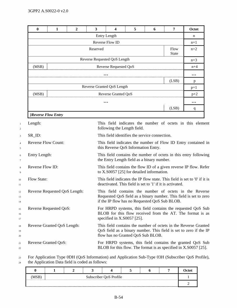
3GPP2 A.S0022-0 v2.0
B-54
0 1 2 3 4 5 6 7 Octet
Entry Length n
Reverse Flow ID n+1
Reserved Flow State
n+2
Reverse Requested QoS Length n+3
(MSB) Reverse Requested QoS n+4
… …
(LSB) p
Reverse Granted QoS Length p+1
(MSB) Reverse Granted QoS p+2
… …
(LSB) q
}Reverse Flow Entry
Length: This field indicates the number of octets in this element 1
following the Length field. 2
SR_ID: This field identifies the service connection. 3
Reverse Flow Count: This field indicates the number of Flow ID Entry contained in 4
this Reverse QoS Information Entry. 5
Entry Length: This field contains the number of octets in this entry following 6
the Entry Length field as a binary number. 7
Reverse Flow ID: This field contains the flow ID of a given reverse IP flow. Refer 8
to X.S0057 [25] for detailed information. 9
Flow State: This field indicates the IP flow state. This field is set to '0' if it is 10
deactivated. This field is set to '1' if it is activated. 11
Reverse Requested QoS Length: This field contains the number of octets in the Reverse 12
Requested QoS field as a binary number. This field is set to zero 13
if the IP flow has no Requested QoS Sub BLOB. 14
Reverse Requested QoS: For HRPD systems, this field contains the requested QoS Sub 15
BLOB for this flow received from the AT. The format is as 16
specified in X.S0057 [25]. 17
Reverse Granted QoS Length: This field contains the number of octets in the Reverse Granted 18
QoS field as a binary number. This field is set to zero if the IP 19
flow has no Granted QoS Sub BLOB. 20
Reverse Granted QoS: For HRPD systems, this field contains the granted QoS Sub 21
BLOB for this flow. The format is as specified in X.S0057 [25]. 22
For Application Type 0DH (QoS Information) and Application Sub-Type 03H (Subscriber QoS Profile), 23
the Application Data field is coded as follows: 24
0 1 2 3 4 5 6 7 Octet
(MSB) Subscriber QoS Profile 1
2
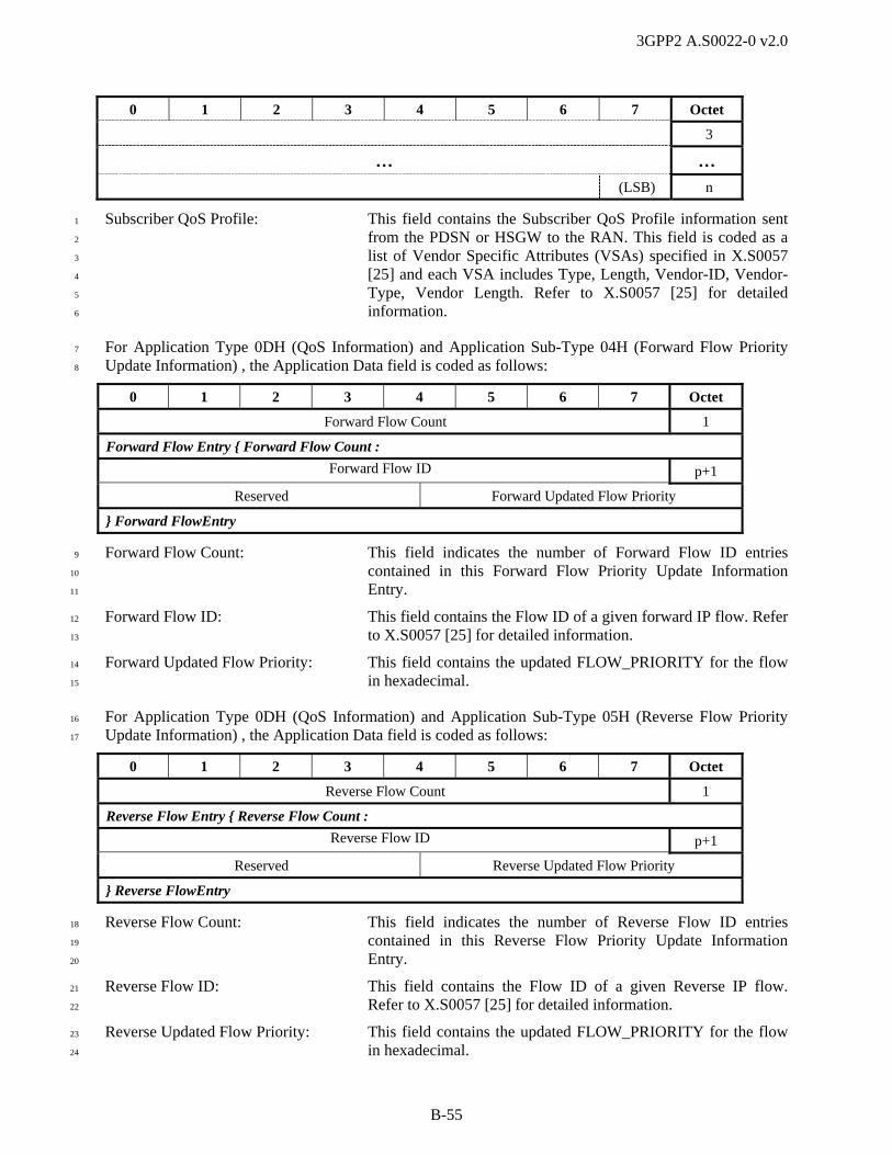
3GPP2 A.S0022-0 v2.0
B-55
0 1 2 3 4 5 6 7 Octet
3
… …
(LSB) n
Subscriber QoS Profile: This field contains the Subscriber QoS Profile information sent 1
from the PDSN or HSGW to the RAN. This field is coded as a 2
list of Vendor Specific Attributes (VSAs) specified in X.S0057 3
[25] and each VSA includes Type, Length, Vendor-ID, Vendor-4
Type, Vendor Length. Refer to X.S0057 [25] for detailed 5
information. 6
For Application Type 0DH (QoS Information) and Application Sub-Type 04H (Forward Flow Priority 7
Update Information) , the Application Data field is coded as follows: 8
0 1 2 3 4 5 6 7 Octet
Forward Flow Count 1
Forward Flow Entry { Forward Flow Count :
Forward Flow ID p+1
Reserved Forward Updated Flow Priority
} Forward FlowEntry
Forward Flow Count: This field indicates the number of Forward Flow ID entries 9
contained in this Forward Flow Priority Update Information 10
Entry. 11
Forward Flow ID: This field contains the Flow ID of a given forward IP flow. Refer 12
to X.S0057 [25] for detailed information. 13
Forward Updated Flow Priority: This field contains the updated FLOW_PRIORITY for the flow 14
in hexadecimal. 15
For Application Type 0DH (QoS Information) and Application Sub-Type 05H (Reverse Flow Priority 16
Update Information) , the Application Data field is coded as follows: 17
0 1 2 3 4 5 6 7 Octet
Reverse Flow Count 1
Reverse Flow Entry { Reverse Flow Count :
Reverse Flow ID p+1
Reserved Reverse Updated Flow Priority
} Reverse FlowEntry
Reverse Flow Count: This field indicates the number of Reverse Flow ID entries 18
contained in this Reverse Flow Priority Update Information 19
Entry. 20
Reverse Flow ID: This field contains the Flow ID of a given Reverse IP flow. 21
Refer to X.S0057 [25] for detailed information. 22
Reverse Updated Flow Priority: This field contains the updated FLOW_PRIORITY for the flow 23
in hexadecimal. 24

3GPP2 A.S0022-0 v2.0
B-56
For Application Type 0DH (QoS Information) and Application Sub-Type FEH (Forward QoS Update 1
Information), the Application Data field is coded as follows: 2
0 1 2 3 4 5 6 7 Octet
Forward Flow Count 1
Forward Flow Entry { Forward Flow Count :
Forward Flow ID p+1
Forward Updated QoS Sub-BLOB Length p+2
(MSB) Forward Updated QoS Sub-BLOB p+3
… …
(LSB) q
} Forward Flow Entry
3
Forward Flow Count: This field indicates the number of Flow ID Entry contained in 4
this Forward QoS Information Entry. 5
Forward Flow ID: This field contains the flow ID of a given forward IP flow. Refer 6
to X.S0057 [25] for detailed information. 7
Forward Updated QoS 8
Sub-BLOB Length: This field contains the number of octets in the Forward Updated 9
QoS Sub-BLOB field as a binary number. 10
Forward Updated QoS Sub-BLOB: This field contains the Updated QoS Sub-BLOB for this flow. 11
Refer to X.S0057 [25] for detailed information. 12
For Application Type 0DH (QoS Information) and Application Sub-Type FFH (Reverse QoS Update 13
Information), the Application Data field is coded as follows: 14
0 1 2 3 4 5 6 7 Octet
Reverse Flow Count 1
Reverse Flow Entry { Reverse Flow Count :
Reverse Flow ID p+1
Reverse Updated QoS Sub-BLOB Length p+2
(MSB) Reverse Updated QoS Sub-BLOB p+3
… …
(LSB) q
} Reverse Flow Entry
15
Reverse Flow Count: This field indicates the number of Flow ID Entry contained in 16
this Reverse QoS Information Entry. 17
Reverse Flow ID: This field contains the flow ID of a given reverse IP flow. Refer 18
to X.S0057 [25] for detailed information. 19
Reverse Updated QoS 20
Sub-BLOB Length: This field contains the number of octets in the Reverse Updated 21
QoS Sub-BLOB field as a binary number. 22
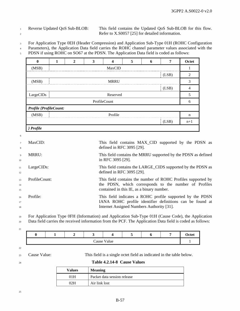
3GPP2 A.S0022-0 v2.0
B-57
Reverse Updated QoS Sub-BLOB: This field contains the Updated QoS Sub-BLOB for this flow. 1
Refer to X.S0057 [25] for detailed information. 2
For Application Type 0EH (Header Compression) and Application Sub-Type 01H (ROHC Configuration 3
Parameters), the Application Data field carries the ROHC channel parameter values associated with the 4
PDSN if using ROHC on SO67 at the PDSN. The Application Data field is coded as follows: 5
0 1 2 3 4 5 6 7 Octet
(MSB) MaxCID 1
(LSB) 2
(MSB) MRRU 3
(LSB) 4
LargeCIDs Reserved 5
ProfileCount 6
Profile {ProfileCount:
(MSB) Profile n
(LSB) n+1
} Profile
6
MaxCID: This field contains MAX_CID supported by the PDSN as 7
defined in RFC 3095 [29]. 8
MRRU: This field contains the MRRU supported by the PDSN as defined 9
in RFC 3095 [29]. 10
LargeCIDs: This field contains the LARGE_CIDS supported by the PDSN as 11
defined in RFC 3095 [29]. 12
ProfileCount: This field contains the number of ROHC Profiles supported by 13
the PDSN, which corresponds to the number of Profiles 14
contained in this IE, as a binary number. 15
Profile: This field indicates a ROHC profile supported by the PDSN 16
IANA ROHC profile identifier definitions can be found at 17
Internet Assigned Numbers Authority [31]. 18
For Application Type 0FH (Information) and Application Sub-Type 01H (Cause Code), the Application 19
Data field carries the received information from the PCF. The Application Data field is coded as follows: 20
21
0 1 2 3 4 5 6 7 Octet
Cause Value 1
22
Cause Value: This field is a single octet field as indicated in the table below. 23
Table 4.2.14-8 Cause Values 24
Values Meaning
01H Packet data session release
02H Air link lost
25
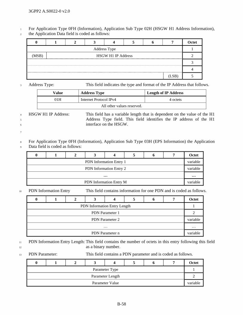
3GPP2 A.S0022-0 v2.0
B-58
For Application Type 0FH (Information), Application Sub Type 02H (HSGW H1 Address Information), 1
the Application Data field is coded as follows: 2
0 1 2 3 4 5 6 7 Octet
Address Type 1
(MSB) HSGW H1 IP Address 2
3
4
(LSB) 5
Address Type: This field indicates the type and format of the IP Address that follows. 3
Value Address Type Length of IP Address
01H Internet Protocol IPv4 4 octets
All other values reserved.
HSGW H1 IP Address: This field has a variable length that is dependent on the value of the H1 4
Address Type field. This field identifies the IP address of the H1 5
interface on the HSGW. 6
7
For Application Type 0FH (Information), Application Sub Type 03H (EPS Information) the Application 8
Data field is coded as follows: 9
0 1 2 3 4 5 6 7 Octet
PDN Information Entry 1 variable
PDN Information Entry 2 variable
… …
PDN Information Entry M variable
PDN Information Entry This field contains information for one PDN and is coded as follows. 10
0 1 2 3 4 5 6 7 Octet
PDN Information Entry Length 1
PDN Parameter 1 2
PDN Parameter 2 variable
… …
PDN Parameter n variable
PDN Information Entry Length: This field contains the number of octets in this entry following this field 11
as a binary number. 12
PDN Parameter: This field contains a PDN parameter and is coded as follows. 13
0 1 2 3 4 5 6 7 Octet
Parameter Type 1
Parameter Length 2
Parameter Value variable

3GPP2 A.S0022-0 v2.0
B-59
Parameter Type: This field indicates the type of parameter included in the Parameter 1
Value field. Possible values are: 01H (APN Information), 02H (APN 2
Key Information), and 03H (P-GW IP Address). 3
Parameter Length: This field contains the number of octets in this PDN Parameter following 4
this field as a binary number. 5
Parameter Value: This field is coded as shown below. 6
When Parameter Type is set to ‘01H’ (APN Information), the Parameter Value is coded as follows: 7
0 1 2 3 4 5 6 7 Octet
(MSB) APN 3
… …
(LSB) m
8
APN: This field contains the fully qualified domain name of the access 9
provider as an ASCII character string. 10
When Parameter Type is set to ‘02H’ (S103 Source GRE Key Information), the Parameter Value is coded 11
as follows: 12
0 1 2 3 4 5 6 7 Octet
(MSB) S103 Source GRE Key 3
4
5
(LSB) 6
13
S103 Source GRE Key: This is a four octet field. This field contains the same value that is used 14
in the Key field in the GRE header on the associated connection between 15
P-GW and HSGW or S-GW. 16
When Parameter Type is set to ‘03H’ (P-GW IP Address), the Parameter Value is coded as follows: 17
Address Type 3
(MSB) P-GW IP Address 4
… …
(LSB) n
18
Address Type: This field indicates the type and format of the IP Address that follows. 19
Value Address Type Length of IP Address
01H Internet Protocol IPv4 4 octets
02H Internet Protocol IPv6 variable
All other values reserved.

3GPP2 A.S0022-0 v2.0
B-60
P-GW IP Address: This field has a variable length that is dependent on the value of the 1
Address Type field. This field identifies the IP address of the P-GW that 2
terminates the GRE connection identified in this NVSE. 3
For Application Type 0FH (Information), Application Sub Type 04H (Additional HSGW Information) 4
the Application Data field is coded as follows: 5
0 1 2 3 4 5 6 7 Octet
HSGW Parameter Entry 1 variable
HSGW Parameter Entry 2 variable
… …
HSGW Parameter Entry N variable
HSGW Parameter Entry This field contains HSGW information and is coded as follows. 6
0 1 2 3 4 5 6 7 Octet
Parameter Type 1
Parameter Length 2
Parameter Value variable
Parameter Type: This field indicates the type of parameter included in the Parameter 7
Value field. Possible values are: 01H (T-HSGW S103 IP Address), 02H 8
(T-HSGW S103 Key), 03H (PMK Information). 9
Parameter Length: This field contains the number of octets in this entry following this field 10
as a binary number. 11
Parameter Value: This field contains parameter information and is coded as follows. 12
When the Parameter Type is set to ‘01H (T-HSGW S103 IP Address)’, the Parameter Value is coded as 13
follows. This parameter shall not be included if the T-HSGW does not support data forwarding over the 14
S103 interface. 15
0 1 2 3 4 5 6 7 Octet
Address Type 3
(MSB) 4
T-HSGW S103 IP Address 5
… …
(LSB) n
Address Type: This field indicates the type and format of the IP Address that follows. 16
Value Address Type Length of IP Address
01H Internet Protocol IPv4 4 octets
02H Internet Protocol IPv6 variable
All other values reserved.
T-HSGW S103 IP Address: This field has a variable length that is dependent on the value of the S103 17
Address Type field. This field identifies the IP address of the S103 18
interface on the T-HSGW. 19

3GPP2 A.S0022-0 v2.0
B-61
When Parameter Type is set to ‘02H’ (T-HSGW S103 Key), the Parameter Value is coded as follows. 1
This parameter shall not be included if the T-HSGW does not support data forwarding over the S103 2
interface. 3
0 1 2 3 4 5 6 7 Octet
(MSB) APN 3
… …
(LSB) m
(MSB) T-HSGW S103 Key m+1
m+2
m+3
(LSB) m+4
APN: This field contains the fully qualified domain name of the access 4
provider as an ASCII character string. 5
T-HSGW S103 Key: This is a four octet field. This field contains the same value that is used 6
in the Key field in the GRE header on the connection from the S-GW to 7
the T-HSGW associated with the specified APN. 8
When the Parameter Type is set to ‘03H (PMK Information)’, the HSGW Parameter Entry is coded as 9
follows. 10
0 1 2 3 4 5 6 7 Octet
Parameter Type = [03H] m
Parameter Length m+1
PMK Count m+2
PMK n Length n
(MSB) PMK-n n+1
… …
(LSB) p
(MSB) PMK-n Lifetime p+1
p+2
p+3
(LSB) p+4
Parameter Type This field indicates the type of timer information. This field shall be set 11
to ‘03H’ (PMK Information). 12
Parameter Length This field contains the number of octets in this entry following this field 13
as a binary number. 14
PMK Count This field shall be set to the number of occurrences of the PMK field in 15
this parameter record. 16
PMK Length This field indicates the length of a PMK in octets. 17
PMK This field contains a PairwiseMasterKey. 18
PMK Lifetime This field indicates the length of time (in seconds) for which the included 19
PMKs are valid as an unsigned 32-bit binary number. 20

3GPP2 A.S0022-0 v2.0
B-62
For Application Type 10H (HRPD Indicators), and Application Sub-Type 01H (Emergency Services) the 1
Application Data field carries the indication of whether emergency services are used. The Application 2
Data field is coded as follows: 3
0 1 2 3 4 5 6 7 Octet
Emergency Services
Reserved 1
4
Emergency Services This field indicates whether emergency services are used. If emergency 5
services are used, the field is set to ‘1’. Otherwise, the field is set to ‘0’. 6
7
8