Embed Size (px)
Citation preview
Abstract—Wireless communication is the need of the hour. In
the present fast paced life, there is a strong urgency for the improvement in the means of communication. A Wireless network using Visible Light Communication (VLC) is a newly emerging trend that can easily pave the way for a comfortable wire-free future. The usage of light as a source of communication is an innovative and not-yet commercialized technology. Such a technology is useful to envision a smarter personal wireless network, underwater communication and also in applications that provide mobile services. This paper aims to explain the concept of VLC through its application to provide Wireless Internet. It elaborates the use of Low Power Light Emitting Diodes (LEDs) for transmission and reception along with the current and future prospects of this technology. It also deals with the technical specifications for constructing such a network for real-time purposes.
Index Terms—Visible Light Communication, Low Power, LEDs, Wireless Communication.
I. INTRODUCTION Light is an indispensable part of our lives. It’s a part of the
electromagnetic spectrum that is visible to the human eye. Artificially created as well as naturally available light is abundant and has never been truly exploited for its value. It lies in the frequency range of 400-790 THz and the wavelength range of 380-750nm. Since the advent of the incandescent light bulb, till today, the concept of lighting is constantly in a phase of growth. From the original Tungsten (Wr) filament light bulbs to the fluorescent light bulbs, and also to the present Light Emitting Diodes (LEDs), there has been nothing but a great surge of development. Considering the tremendous speed of light (3x10⁸ meters per second), it is a useful tool for high speed requirements of communication especially over very large distances. The medium for such a communication is an optical fiber. A hair-line thin tube is the channel to transport light from one point to another. Light always propagates linearly but at the instance of a change in medium, there is a deviation of the light rays. This property of refraction is the basic nature of communication. But if the light deviates, the complete information transmitted is not sent to the receiver. So the concept of Total Internal Reflection comes into picture. This is the main idea behind Optical fibers. The angle of incidence of the light from the beginning of the fiber to the nearest boundary is lower than the critical angle which causes the light to reflect back into the inner surface rather than being transmitted away from the fiber. Such reflections maintain the entire stream and thus
Manuscript received September 20, 2011. Akassh. A. Mishra is working with Hewlett Packard, Bangalore, India (e-mail: [email protected]). Neelesh S. Salian is pursuing his Bachelor of Engineering from St Francis
Institute of Technology, University of Mumbai, India. (e-mail: nss7790@gmail. com).
Optical fiber communication is possible.
II. WIRELESS COMMUNICATION The 21st century has seen a growing demand for wire-free
technology considering the extreme data requirements and the need for mobility. Wireless Local Area Networks (WLAN) have resolved the issues of mobility and high speed data transmissions. Moreover they are useful in the applications where wired technology is impractical. Wireless communication has thus been uplifted to a utility-like status considering the immense dependency. These networks are scaled to private home networks, organizational private networks and even a larger metropolitan area network for an entire city. Wireless data transmission is achieved through the electromagnetic waves, specifically radio waves (spectrum range for wireless communication: 9 kHz to 300GHz). The transmission can wirelessly occur because of microwave communication for long-range communication and even using Infrared (IR) for short-range communication like remote control.
A. Advantages 1) Any type of data can be wirelessly transmitted to another
suitable device. Audio, video, internet, text are easily transmitted over the wireless medium to a compatible device (receiver)
2) The term ‘wireless’ suggests the lack of any physical wiring required between communicating devices. Thus it proves to be a cost effective measure.
3) The infrastructure for radio transmission has spanned the globe and hence the technology can be implemented anywhere. The cellular base stations with radio masks have already been set up and with the availability of wireless communicating devices; this spectrum can be easily exploited.
4) Wireless communication sees no physical hindrances. The radio waves can transmit through walls and thus a entire household can answer to a single network.
5) Portable wireless devices require the consistent and high speed data on the move and thus wireless technology has made it easier to access data.
B. Disadvantages 1) Transmission Capacity: Wireless communicating
networks utilize radio waves which has a limited bandwidth for transmission and reception. The current demand for wireless data is exceeding as we speak and considering the frequency limitations, the spectrum seems insufficient. Though this technology provides mobility, it restricts the usage considering the spectral availability.
2) Energy: The depleting energy resources only provoke the world to become wary of the excessive use of energy. So any new technology is carefully monitored to avoid
Internet using Visible Light Communication
Akassh A. Mishra and Neelesh S. Salian
IACSIT International Journal of Engineering and Technology, Vol. 3, No. 5, October 2011
577
unnecessary use of energy. The radio transmission stations are heavy energy consumers. The cost for powering the base stations is quite extensive and since the demand is consistently high, the energy consumption continues to wax. Moreover, the heat generated by such a station needs to be reduced. So in turn, there is energy applied to cool these stations apart from the on-going radio transmission. So the overall efficiency of such a station drops to 5%. Some stations also use expensive fuel cell technology to provide power.
3) Emissions: Low levels of radio-frequency are harmful to human health. In order to prevent the exposure to electromagnetic radiation, the base station designed is strictly regulated with changes in specifications like antenna height and even the location. Thus the hardware expenditure needs to be adjusted.
4) Lack of ubiquitous network: Wireless technology has its availability restrictions. The usage of wireless devices is prevented in aircrafts, hospitals and highly secure locations. So the lack of availability fails to fulfill the need.
5) Security: The prime concern of any communication customer is the security of transmission. The confidentiality and privacy aspects of the message should be intact whilst transmission. Wireless technology is easily prone to attacks from any other source. The unbounded wireless transmission cannot prevent the interception of information by any other device. Probably the use of security techniques like keys, encrypted data could suffice the need for security but the system still remains vulnerable to any new attack. Thus, the security measures need to be heightened to ensure a secure and risk free transmission.
III. ORTHOGONAL FREQUENCY DIVISION MULTIPLEXING Orthogonal Frequency Division multiplexing is a
frequency multiplexing technique incorporating digital multi-carrier modulation. This technique is useful for the transmission of multiple data at a high speed. OFDM divides the data into several channels which are transmitted parallel along the medium on different bands. There are subcarriers of data which consist of multiple channels of data. OFDM uses Fast Fourier Transform (FFT) at the receiver’s end and Inverse Fast Fourier Transform(IFFT) at the sender’s end. The modulation technique is thus made efficient.
IV. MAIN IDEA Considering the disadvantages of the wireless technology,
we need to reform our outlook by using an innovative and cost effective communication principle. The ever-availability of light can never be neglected and it prompts a different view into aspects of wireless communication. To begin with, the currently deployed systems for wireless technology utilize the Radio Waves which is a part of the Electromagnetic Spectrum. The infrastructure as well as the devices has adjusted to this format of communication which has but a limited spectrum for transmission and reception. Radio spectrum for the wireless communication is somewhat limited and needs to find an alternative.
Approaching the visible light spectrum, we find a broader range to allow much greater transmission from one device to another. Thus, with a larger capacity, the visible light spectrum is the next best thing for the purpose of high speed data transmission. The actual working of visible light communication technique will, of course, need infrastructure. But the ever-available light that illuminates every home, street is just the hardware that we need at no extra cost. The light bulbs have to adjusted and used for the sake of data transmission rather than illumination.
Apart from the hardware costs and spectral differences, there is a significant difference in energy consumption too. The cost of cooling the cellular base stations is an extra burden considering the already incurred expenditure on the infrastructure. Thus, for our wireless transmission, we need to employ a different source of light (i.e. LEDs). These cost-efficient light sources are the future of lighting which can be a better alternative and also pave the way for an energy efficient communication technique.
The aspect of availability in wireless technology is somewhat constrained sometimes. But with Visible Light, such problem wouldn’t occur considering its omnipresence. The presence of light sources surrounds every aspect of life ans so communication can be possible whenever and however it’s necessary.
The data to be transmitted is converted into the frequency domain which is then transmitted to the base stations and then via a local access point to the user device. But in case of lighting, the hardware is predominantly, wired and in the form of optical fibers. These thin transparent tubes of glass carry the transmitted data over a larger distance than conventional co-axial wiring. The concept of such optical fiber communication has yet not peaked in many areas of the world. This is because of the existing hardware and even the extra cost for overhauling the entire infrastructure mechanism to incorporate a new technology is somewhat unacceptable.
The high speed data transmission from the optical network or even a co-axial cable network can be further propagated by using LEDs. The essence of this concept is the seamless transfer of data via the medium of light. The optical or co-axial cable needs to supply the data to be forwarded via the medium of light.
Another aspect of wireless technology, which must not be overlooked, is transmission security. The wireless network of the present age cannot be classified as a completely safe or secure transmission medium. The unbounded transmission of wireless data (i.e. like within the rooms of a house) increases the vulnerability to malicious attacks. Encryption techniques using private keys and coded messages cannot suffice the entire need for security. The attacks could come from different rooms of a house. So, considering the real world implementations, wireless networks have provide a great deal of concern and worry about security. This issue is another reason to opt for VLC technology. The transmission of data is through the illumination which has a limited or expansive range depending on the source of light. Only the devices within the vicinity of the illumination can exploit the use of the medium and hence to achieve any kind of attack, the attacker (device) must be physical present within the light’s
IACSIT International Journal of Engineering and Technology, Vol. 3, No. 5, October 2011
578
illumination. Thus the security is somewhat ensured in the case VLC.
V. WORKING OF MAIN IDEA With the advantages of VLC in mind, the network setup
shall be explained further. Initially the requirement would be to use the Low Power LEDs instead of the incandescent light bulbs. LEDs are semi-conductor devices which at the beginning emitted low-intensity red light, but are now available to transmit in the visible, ultraviolet as well as infrared wavelengths. The advantage of LEDs over a conventional light bulb is primarily the energy consumption which is quite higher for incandescent light bulbs. LEDs are low powered transmitters which have a greater life than its illumination counterparts. There are absolutely no health concerns while incorporating the use of LEDs and hence we find them in almost all walks of life.
The second reason for the use of LEDs would be its property of intensity modulation. The output (illumination intensity) of an LED bulb can be physically controlled and varied as per data that needs to be sent. This feature can enable the transmission of large data by changes the frequency of the illumination of the LED bulb. Flickering of the LED is the indication of transmission. When the data to be sent is of a higher order of frequency, the flickering of the LED is so rapid that the changes become invisible to the naked eye. So the network configuration will consist of an LED transmitter along with a receiver. The receiver will identify the correct intensity based on the signal amplitude and convert it into electrical signals which in turn will be resulting in a data stream.
For such type of transmission, we can refer the use of a remote control for a television. The remote end has an infrared light which informs the television set about the operations like volume control, channel switch, etc. It involves the sending of bit streams to the receiver at the television to understand the next request. But this transmission is simple and does not involve much load or need much power. The practical application of VLC is primarily for a faster and higher requirement of data which works on the principle of Orthogonal Frequency Division Multiplexing (OFDM).
VI. SYSTEM IMPLEMENTATION In OFDM, the sub-carrier frequencies are chosen in such a
way that the sub-carriers are orthogonal to each other i.e. that cross-talk between the sub-channels is eliminated and inter-carrier guard bands are not required. This greatly simplifies the design of both the transmitter and the receiver. Unlike conventional FDM, a separate filter for each sub-channel is not required. The transmitter utilizes all carriers to send its data as coded quantity at each frequency carrier, which can be Quadrature-Amplitude Modulation (QAM) or Binary PSK (BPSK).
In OFDM there are more than one transmission path between transmitter and receiver. Thus the received signal is the sum of the many versions of the signal with varying delay
and attenuation. Thus the original stream may lose some information due to this attenuation. The received signal is dependent upon the transmitted signal and due to Inter Symbol Interference (ISI) the information is lost. Thus equalization is necessary to be done. ISI increases as the data rate increases which is detrimental to transmission.
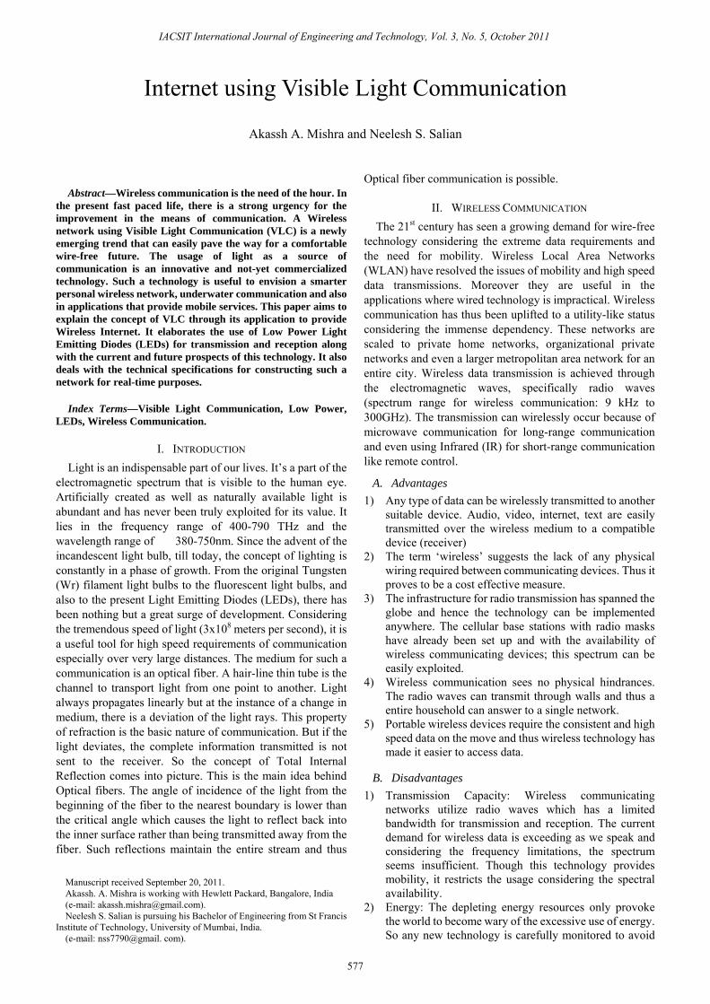
Fig. 1. Mathematically Orthogonal
OFDM transmits each signal sub carrier with a different
frequency to avoid the occurrence of ISI. Frequencies are generally chosen such a way as to have integral number of cycles in the signal period. Thus the figure above shows that signals are mathematical orthogonal to each other.
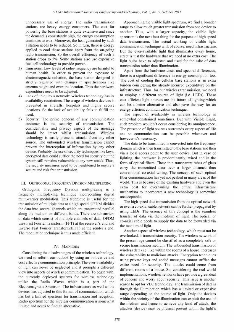
VII. TRANSMISSION OF DATA Each piece of information through OFDM signals is
transmitted through the medium by varying the phase and amplitude of each subcarrier to adjust to the variation in data.
Fig. 2. OFDM Transmitter
A. Description A Random Bit Generator serves as the message source. It
creates a random row vector with the length specified. Symbol duration = Ts. 1) BPSK Modulator/ QAM Unit: This phase modulates the
incoming data stream to be fed into the Serial to Parallel Converter.
2) Serial to Parallel Converter: Partitions the incoming data for separation into n sub-carriers. The symbols have duration of n. Ts, thereby expanding the symbols in time.
3) Inverse Fast Fourier Transform unit: This multiple
IACSIT International Journal of Engineering and Technology, Vol. 3, No. 5, October 2011
579
stream of data is sent to the Inverse Fast Fourier Transform unit: The information is multiplied by the corresponding carrier gk(t) and the sum of such modulated sinusoidal form the transmit signals. The sum of all modulated signals (having a frequency separation of 1/T) will produce the resulting s(t), a signal in the time domain. This summation of the signals is a multiple stream time domain signal which is fed into a Parallel to Serial Converter. This block multiplexes the modulated data for transmission over the channel.
4) Separating Real and Imaginary parts of Signal: As the figure suggests the real and imaginary part of the modulated serial signal should be separated to be transmitted via two separate LEDs. The transmission will depend on the LEDs after this phase.
5) LEDs: A constant DC component K is added on top of the signal, and this is used to drive the LEDs. These low powered diodes will carry the information from both the real and imaginary parts of the signal to forward into the channel. LEDs will oscillate the illumination (flicker) as per the input signal and thus emit the light at required frequency. The higher order oscillations for high speed data transmission generate a greater amount of frequency and so the flickering of the LEDs are invisible to the human eye and appear to be like a normal light bulb during transmission.
6) Additive White Gaussian Noise (AGMN): This block simulates the ambient noise in the system. It first measures the power of the noise in the signal and adjusts the variance of the noise to meet the specified Signal-to-Noise Ratio (SNR).
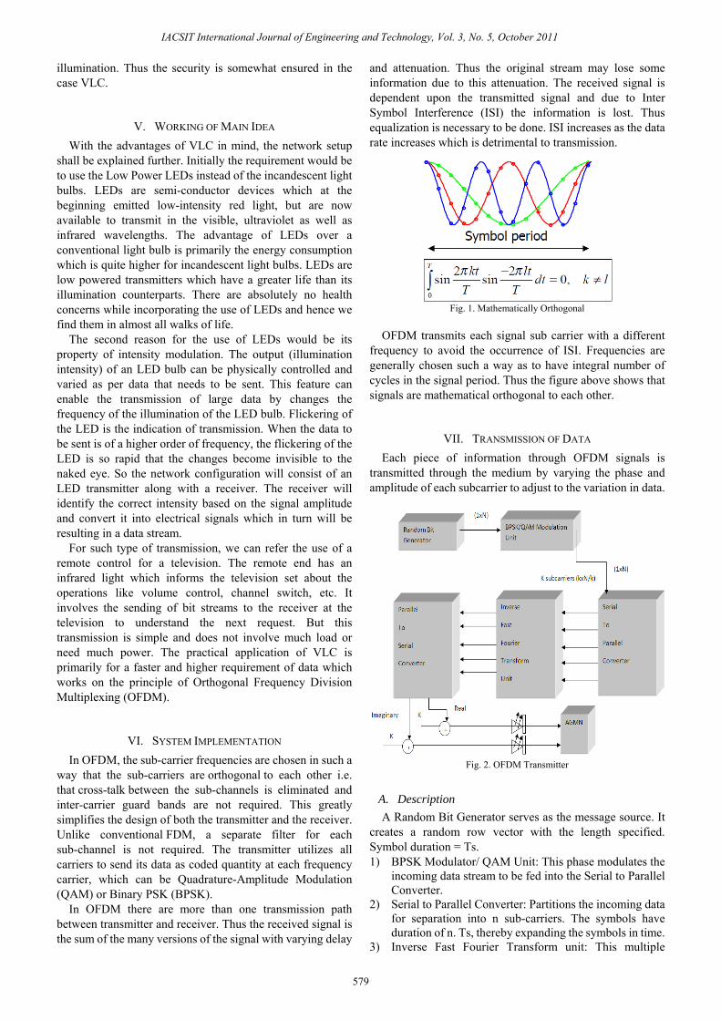
VIII. RECEIVING OF DATA
Figure 3 OFDM Receiver
A. Description 1) Photo Diode: The photo diode acts as a current source. It
converts the incoming optical luminosity into current. This is then converted into a voltage with the use of a trans-impedance amplifier.
2) Constant, K: The constant component K is subtracted from the received data.
3) Fast Fourier Transform: It does the exact opposite functioning of the IFFT unit. The FFT unit changes the time domain signal back into the frequency domain by using Integration.
4) Binary Phase Shift Keying Demodulator: It does the job of demodulating the received signal to allow to be understood by the system to interpret the actual data.
5) Bit Error Calculator: It is essential in every transmission to ensure the absence of errors. This block compares the received data to the transmitted data and calculates the number of bits that were in error.
The original signal which was changed in phase and amplitude to incorporate difference in information is referred to in the receiver end. The changes are checked to finally form the actual data.
IX. PROS AND CONS OF OFDM FOR DATA TRANSMISSION
A. Advantages 1) The entire visible specturm is available at our disposal.
In Radio waves, signals overlap and hence the information for that channel has been compromised. So, the OFDM avoids this condition to prevent overlap and maintains a 1/T frequency difference.
2) OFDM divides the channel into multiplple channels which are narrowband and flat fading. Thus OFDM is more resistant to frequency selective fading than single carrier systems are.
3) It avoids Inter-Symbol Interference by using a cyclic prefix.
4) Channel equalization becomes simpler than by using adaptive equalization techniques with single carrier systems.
5) OFDM is efficient to compute since it uses Inverse Fast Fourier Transform(IFFT) and Fast Fourier Transform(FFT) to implement modulation and demodulation respectively.
6) Sensitivity to sample timing offsets is lower its counterparts.
B. Disadvantages 1) Synchronization: One of the crucial problems in the
receiver is to sample the incoming signal correctly. If the wrong sequence of samples is processed, the Fast Fourier Transform shall not correctly recover the received data on the carriers.
2) Phase noise: At the receiver, a local oscillator can add phase noise to an OFDM signal, for example. The phase noise could so have two effects those are: Common Phase Error (CPE) due to a rotation of the signal constellation and, Inter Carrier Interference (ICI), similar to additive Gaussian noise. Unfortunately, ICI is more difficult to overcome, due to the additive noise, which is different for all carriers.
3) Frequency error: An OFDM system can be subject to two types of frequency error. They are Frequency offset (as might be caused by the tolerance of the local oscillator frequency) and Error in the Symbols.
X. PRACTICAL ANALYSIS AND DEMONSTRATION Visible light will be extremely useful for wireless data
transmission within a given space. Our idea is to design a model which implements this phenomenon.
IACSIT International Journal of Engineering and Technology, Vol. 3, No. 5, October 2011
580
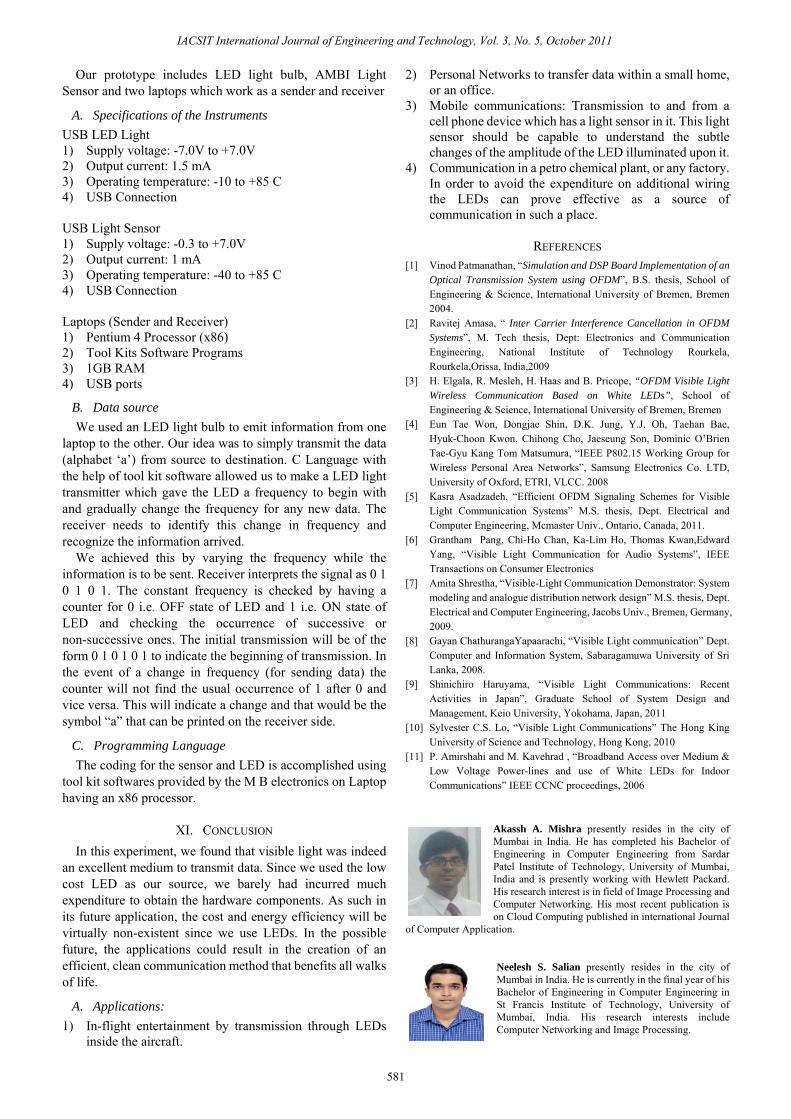
Our prototype includes LED light bulb, AMBI Light Sensor and two laptops which work as a sender and receiver
A. Specifications of the Instruments USB LED Light 1) Supply voltage: -7.0V to +7.0V 2) Output current: 1.5 mA 3) Operating temperature: -10 to +85 C 4) USB Connection USB Light Sensor 1) Supply voltage: -0.3 to +7.0V 2) Output current: 1 mA 3) Operating temperature: -40 to +85 C 4) USB Connection Laptops (Sender and Receiver) 1) Pentium 4 Processor (x86) 2) Tool Kits Software Programs 3) 1GB RAM 4) USB ports
B. Data source We used an LED light bulb to emit information from one
laptop to the other. Our idea was to simply transmit the data (alphabet ‘a’) from source to destination. C Language with the help of tool kit software allowed us to make a LED light transmitter which gave the LED a frequency to begin with and gradually change the frequency for any new data. The receiver needs to identify this change in frequency and recognize the information arrived.
We achieved this by varying the frequency while the information is to be sent. Receiver interprets the signal as 0 1 0 1 0 1. The constant frequency is checked by having a counter for 0 i.e. OFF state of LED and 1 i.e. ON state of LED and checking the occurrence of successive or non-successive ones. The initial transmission will be of the form 0 1 0 1 0 1 to indicate the beginning of transmission. In the event of a change in frequency (for sending data) the counter will not find the usual occurrence of 1 after 0 and vice versa. This will indicate a change and that would be the symbol “a” that can be printed on the receiver side.
C. Programming Language The coding for the sensor and LED is accomplished using
tool kit softwares provided by the M B electronics on Laptop having an x86 processor.
XI. CONCLUSION In this experiment, we found that visible light was indeed
an excellent medium to transmit data. Since we used the low cost LED as our source, we barely had incurred much expenditure to obtain the hardware components. As such in its future application, the cost and energy efficiency will be virtually non-existent since we use LEDs. In the possible future, the applications could result in the creation of an efficient, clean communication method that benefits all walks of life.
A. Applications: 1) In-flight entertainment by transmission through LEDs
inside the aircraft.
2) Personal Networks to transfer data within a small home, or an office.
3) Mobile communications: Transmission to and from a cell phone device which has a light sensor in it. This light sensor should be capable to understand the subtle changes of the amplitude of the LED illuminated upon it.
4) Communication in a petro chemical plant, or any factory. In order to avoid the expenditure on additional wiring the LEDs can prove effective as a source of communication in such a place.
REFERENCES [1] Vinod Patmanathan, “Simulation and DSP Board Implementation of an
Optical Transmission System using OFDM”, B.S. thesis, School of Engineering & Science, International University of Bremen, Bremen 2004.
[2] Ravitej Amasa, “ Inter Carrier Interference Cancellation in OFDM Systems”, M. Tech thesis, Dept: Electronics and Communication Engineering, National Institute of Technology Rourkela, Rourkela,Orissa, India,2009
[3] H. Elgala, R. Mesleh, H. Haas and B. Pricope, “OFDM Visible Light Wireless Communication Based on White LEDs”, School of Engineering & Science, International University of Bremen, Bremen
[4] Eun Tae Won, Dongjae Shin, D.K. Jung, Y.J. Oh, Taehan Bae, Hyuk-Choon Kwon, Chihong Cho, Jaeseung Son, Dominic O’Brien Tae-Gyu Kang Tom Matsumura, “IEEE P802.15 Working Group for Wireless Personal Area Networks”, Samsung Electronics Co. LTD, University of Oxford, ETRI, VLCC. 2008
[5] Kasra Asadzadeh, “Efficient OFDM Signaling Schemes for Visible Light Communication Systems” M.S. thesis, Dept. Electrical and Computer Engineering, Mcmaster Univ., Ontario, Canada, 2011.
[6] Grantham Pang, Chi-Ho Chan, Ka-Lim Ho, Thomas Kwan,Edward Yang, “Visible Light Communication for Audio Systems”, IEEE Transactions on Consumer Electronics
[7] Amita Shrestha, “Visible-Light Communication Demonstrator: System modeling and analogue distribution network design” M.S. thesis, Dept. Electrical and Computer Engineering, Jacobs Univ., Bremen, Germany, 2009.
[8] Gayan ChathurangaYapaarachi, “Visible Light communication” Dept. Computer and Information System, Sabaragamuwa University of Sri Lanka, 2008.
[9] Shinichiro Haruyama, “Visible Light Communications: Recent Activities in Japan”, Graduate School of System Design and Management, Keio University, Yokohama, Japan, 2011
[10] Sylvester C.S. Lo, “Visible Light Communications” The Hong King University of Science and Technology, Hong Kong, 2010
[11] P. Amirshahi and M. Kavehrad , “Broadband Access over Medium & Low Voltage Power-lines and use of White LEDs for Indoor Communications” IEEE CCNC proceedings, 2006
Akassh A. Mishra presently resides in the city of Mumbai in India. He has completed his Bachelor of Engineering in Computer Engineering from Sardar Patel Institute of Technology, University of Mumbai, India and is presently working with Hewlett Packard. His research interest is in field of Image Processing and Computer Networking. His most recent publication is on Cloud Computing published in international Journal
of Computer Application.
Neelesh S. Salian presently resides in the city of Mumbai in India. He is currently in the final year of his Bachelor of Engineering in Computer Engineering in St Francis Institute of Technology, University of Mumbai, India. His research interests include Computer Networking and Image Processing.
IACSIT International Journal of Engineering and Technology, Vol. 3, No. 5, October 2011
581


![[IJET-V1I3P9] Authors :Velu.S, Baskar.K, Kumaresan.A, Suruthi.K](https://img.pdfslide.us/doc/110x75/55cf8cb75503462b138f2c41/ijet-v1i3p9-authors-velus-baskark-kumaresana-suruthik-55fafbdeb8507.jpg)
![[IJET V2I3P5] Authors: Jamuna H G, Shobha Hugar](https://img.pdfslide.us/doc/110x75/58ed96711a28ab78348b46e1/ijet-v2i3p5-authors-jamuna-h-g-shobha-hugar.jpg)
![[IJET V2I5P2] Authors:Galal Ali Hassaan](https://img.pdfslide.us/doc/110x75/587671c91a28abd0018b63f3/ijet-v2i5p2-authorsgalal-ali-hassaan.jpg)
![[IJET V2I5P7] Authors: Mr. Vaibhav A. Kalhapure, Dr.R.R.Navthar](https://img.pdfslide.us/doc/110x75/5883d1b41a28abb7308b6a4b/ijet-v2i5p7-authors-mr-vaibhav-a-kalhapure-drrrnavthar.jpg)
![[IJET-V1I5P4] Authors :Murugan, Avudaiappan, Balasubramanian](https://img.pdfslide.us/doc/110x75/58e6991e1a28ab5c0f8b5b5b/ijet-v1i5p4-authors-murugan-avudaiappan-balasubramanian-58e69c6d6858a.jpg)


![[IJET-V1I4P10] Authers :EiEi Thwe, Theingi](https://img.pdfslide.us/doc/110x75/55cf8559550346484b8d137f/ijet-v1i4p10-authers-eiei-thwe-theingi-55d475671ddfa.jpg)

![[IJET V2I4P8] Authors: Anju.S, Achu Govind K R](https://img.pdfslide.us/doc/110x75/588035591a28ab9f0f8b72c3/ijet-v2i4p8-authors-anjus-achu-govind-k-r.jpg)
![[IJET-V1I6P21] Authors : Easwari.N , Ponmuthuramalingam.P](https://img.pdfslide.us/doc/110x75/587096431a28ab412b8b6847/ijet-v1i6p21-authors-easwarin-ponmuthuramalingamp.jpg)

![[IJET V2I5P15] Authors: V.Preethi, G.Velmayil](https://img.pdfslide.us/doc/110x75/587096461a28ab412b8b685b/ijet-v2i5p15-authors-vpreethi-gvelmayil.jpg)
![[IJET V2I5P21] Authors: SIRGIREDDY CHINNAANKI REDDY, N.KEERTHI](https://img.pdfslide.us/doc/110x75/587096461a28ab412b8b684f/ijet-v2i5p21-authors-sirgireddy-chinnaanki-reddy-nkeerthi.jpg)
![[IJET V2I3P6] Authors: Ajeeth, Sandhya raani M](https://img.pdfslide.us/doc/110x75/58ef9ccd1a28abbb588b456d/ijet-v2i3p6-authors-ajeeth-sandhya-raani-m.jpg)

![[IJET V2I3P9] Authors: Ruchi Kumari , Sandhya Tarar](https://img.pdfslide.us/doc/110x75/588aab5e1a28ab4c308b6275/ijet-v2i3p9-authors-ruchi-kumari-sandhya-tarar.jpg)
![[IJET V2I4P2] Authors:Damanbir Singh, Guneet Kaur](https://img.pdfslide.us/doc/110x75/58edce381a28abb4318b4641/ijet-v2i4p2-authorsdamanbir-singh-guneet-kaur.jpg)
![[IJET-V2I1P11] Authors:Galal Ali Hassaan](https://img.pdfslide.us/doc/110x75/58ef54201a28abda518b457d/ijet-v2i1p11-authorsgalal-ali-hassaan.jpg)
![[IJET V2I3P4] Authors: Manjunath Aski, Prathibha P](https://img.pdfslide.us/doc/110x75/588035781a28ab9f0f8b7319/ijet-v2i3p4-authors-manjunath-aski-prathibha-p.jpg)
![[IJET V2I5P22] Authors: Gangasani Ravikumar Reddy, M.Suneetha](https://img.pdfslide.us/doc/110x75/587096461a28ab412b8b684d/ijet-v2i5p22-authors-gangasani-ravikumar-reddy-msuneetha.jpg)

![[IJET V2I5P23] Authors:Pramod Kumar](https://img.pdfslide.us/doc/110x75/587096461a28ab412b8b684b/ijet-v2i5p23-authorspramod-kumar.jpg)

![[IJET V2I5P17] Authors: S.AnnapurnaDevi, P. Ramesh Kumar](https://img.pdfslide.us/doc/110x75/587096461a28ab412b8b6857/ijet-v2i5p17-authors-sannapurnadevi-p-ramesh-kumar.jpg)
