Embed Size (px)
Citation preview

8/3/2019 IJET Format Last Date Feb 10
http://slidepdf.com/reader/full/ijet-format-last-date-feb-10 1/8
M. Mohammadha Hussaini et al. / International Journal of Engineering and Technology Vol.2 (4), 2010, 297-304
DYNAMIC RESPONSE OF WIND POWER
GENARATORS USING STATCOMM.Mohammadha Hussaini1, Dr. R. Anita2
1&2Institute of Road and Transport Technology, EEE Department, Erode, India
Abstract —
This paper investigates the steady state performance of
STATCOM based on 6 pulse voltage sourced converter by
which the stator flux oriented vector control of terminal
voltage for SEIG is obtained. The complete digital simulationof the STATCOM and wind turbine, self excited induction
generator (SEIG) are performed using the power system
blockset (PSB) while the control system blockset is modeled
using simulink. To increase the transient stability conditions of the generator a statcom is introduced as the active VAR
supporter. The paper qualifies and quantifies the improved
short term voltage and rotor stability performance obtainedwhen a STATCOM is introduced during different types of failure events in the connected power system.
Keywords: wind turbine, SEIG, STATCOM,, control of dcvoltage.
INTRODUCTION
The working principle of the wind turbine includesthe
following conversion processes: the rotor extracts the kineticenergy from the wind creating genearto torque and the
generator converts theis torque into electricity and feeds it into
the grid. Presently there are three main turbine types abailable.
They are Squirrel-cage induction generator
Doubly fed induction generator.
Direct-drive synchronous generator.
The first one which is the simplest and oldest system
consists of a conventional directly grid-coupled squirrel caged
induction generator. The slip, and the result rotor speed of the
Generator varies with the amount of power generated . therotor speed variation is small , approximately 1% to 2%,and
hence this is normally referred as a constant speed turbine.
The other two generationg systems are variable –speed
systems. In the doubly fed induction generator, a back to back
voltage source converter feeds the three phase rotor winding ,Resulting that the mechanical and electrical rotor frequency are
decoupled and the electrical stator and rotor frequency can
match independently of the mechanical rotor speed. In thedirect-drive synchronous generator, the generator is completely
decoupled from the grid by power electronics, as a converter is
connected to the stator winding and another converter is
connected to the grid. Thus the total power delivered by thewind power is transmitted by an HVDC link.
Figure 1: three main generating systems presently used in wind turbines:
Top : Squirrel cage induction generator;
Middle : Doubly fed induction generator;
Bottom : direct-drive synchronous induction generator.
ISSN : 0975-4024 297

8/3/2019 IJET Format Last Date Feb 10
http://slidepdf.com/reader/full/ijet-format-last-date-feb-10 2/8
M. Mohammadha Hussaini et al. / International Journal of Engineering and Technology Vol.2 (4), 2010, 297-304
Figure 2: Torque-Speed Characteristics
Considering the SEIG type of wind turbine which is themost commonly used wind turbine (simple and economic) this
paper will concentrated on evaluating the performance of this
type of generator.
The slip of a motor, s which is defined as the slip of the rotor
with respect to the stator magnetic field, can be given as
Ne – Nr
S = ----------------------- Nr
Ne- synchronous speed in rpm
Nr- rotor speed in rpm.
The speed at which the Rotating magnetic field rotatesdepends on the supply frequendy. When the rotor totates at a
speed less than the speed of the RMF the induction machine
acts as a motor. The slip at this point is positive as the rotor speed is less than the stator speed(RMF speed). When thespeed of the rotor is greater than the speed of the stator the
machine acts as a generator delivering electrical power as
output. At this juncture the speed of the rotor is greater than the
speed of the stator; hence slip is negative, the RMF can bereversed by interchanging any two terminals of the syooy.
While doing so the machine tends to rotate in opposite
direction. This region is known as the breaking region. Slip of
the machine is greater than one in this region.The torque speedcharacteristics of the induction.Machine is shown in the figure
2.
D-Q AXES INDUCTION MACHINE MODEL
Using D-Q representation the induction machine can be
modelled as shown in figure. This representation is a general
model based on the assumption that the supply voltage can
either be applied to the both the stator and or rotor terminals. Ingeneral power can be supplied to the induction machine(motor)
or extracted from it (generator). If the electrical power is
applied to the induction machine then rotor will start to rotateand the machine is operating as a motor.
On the other hand, if mechanical power is applied to the rotor
of the induction machine then machine will convertmechanical power to electrical power. In this case the machine
Is operating as an induction generator. When the induction
machine is operating as the generator is connected to the grid
or supplying an isolated load, driven by an external primemover, then the rotor should be driven above synchronous
speed.
When the machine is operated as a motor , power flows fromthe stator to the rotor, crossing the airgap.However in
generating mode of operation, power flows from the rotor to
the stator. Only these two modes are dealt with in this
investigation. The braking region where the rotor rotatesopposite to the direction of the rotating magnetic field, is not
dealt with here. The conventional model and the (D-Q) axes
model are the same for steady state analysis.
Using the matrix shown in equation , the d_q representation
given below can be redrawn in detain, in a stationary stator
reference frame with separate direct and quadrature axescircuits.
ISSN : 0975-4024 298

8/3/2019 IJET Format Last Date Feb 10
http://slidepdf.com/reader/full/ijet-format-last-date-feb-10 3/8
M. Mohammadha Hussaini et al. / International Journal of Engineering and Technology Vol.2 (4), 2010, 297-304
Fig: detailed d-q representation of induction machine in
stationary reference frame (a) d-axes circuit (b) q-axis circuit
From the stator side (for simplicity superscript “s” which
indicates stationary reference frame is not included with
currents, voltages and flux linkages)
λ ds= Lsids + Lmidr
λ qs= Lsiqs+Lmiqr
νds = R sids + dλ ds/dt
νqs = R siqs + dλ qs/dt
from the rotor side
λ dr= Lmidr + Lridr
λ qr =Lmiqs + Lriqr
νdr = R ridr + dλ dr/dt +ωrλ qr
νqr= R riqr + dλ qr/dt - ωr
for the air gap flux linkage
λ dm= Lmimd = Lmids + Lmidr
λ qm= Lmimq = Lmiqs + Lmiqr
the stator electrical input powet to the induction machine
during motoring iperation or the stator electrical output power
in generating mode is given by
Pe = 3/2 (ids νds + iqs νqs)
The electromagnetic torque Te is given by
Te = 3/2 Pp λ m × Ir
Where, λm – air gap flux linkage
I r – rotor current space vector
P p- number of pole pairs of the induction machine.
Solving the cross product in Equation gives
Te = 3/2 P pLm(iqsidr - idsiqr )
The mechanical equation in the motoring region is
Te = J dωm/dt + Dωm + Tm
and in the generating region it is given as
Tm =J dωm/dt + Dω+ Te
Where T m – Mechanical torque in the shaft, Nm
T e – Electromagnetic torque, NM
ωm – Mechanical shaft speed ( ωm = ωr /P p ) rad/sec
D – Friction coefficient, Nm/rad/sec
J − Inertia, Kg-m2
The mechanical power generated during motoring or the
mechanical
power required to drive the induction generator is given by
Pm=Teωm
GENERATOR USING THREE AC
CAPACITORS
Any induction machine requires excitation current to
magnetise the core and produce a rotating magnetic field. The
excitation current for an induction generator connected to an
external source, such as the grid, is supplied from that external
source. If this induction generator is driven by a prime mover
above the synchronous speed, electrical power will be
generated and supplied to the external source. An isolated
induction generator without any excitation will not generate
voltage and will not be able to supply electric power
irrespective of the rotor speed.
In general an induction generator requires reactive
power for its operation. Three charged capacitors connected to
the stator terminals of the induction generator can supply the
reactive power required by the induction generator. Provided
that the conditions for self-excitation are satisfied the charged
capacitors cause the terminal voltage to build up at the stator terminalsof the induction generator. When the harged
capacitors are connected to the terminals a transient exciting
current will flow and produce a magnetic flux. This magnetic
flux will generate voltage and the generated voltage will be
able to build the charge in the capacitors. As the charge
increases, more exciting current is supplied to the induction
generator. The magnetic flux continues to increase hence
producing a higher generated voltage. In this way voltage is
built up.
However, if the capacitors are not charged, and a
remnant magnetic flux in the core exists, then a small voltage
will be generated at the terminals of the induction generator
due to that remnant flux. This small voltage will charge the
capacitor. The charged capacitor will now be able to produce a
small exciting current. With time the exciting current grows
and produces magnetic flux more than the remnant magnetic
flux and voltage will be built up. This is similar to the the
way that current and voltage interact in a resonant circuit. For
the voltage to build up across the terminals of the induction
ISSN : 0975-4024 299

8/3/2019 IJET Format Last Date Feb 10
http://slidepdf.com/reader/full/ijet-format-last-date-feb-10 4/8
M. Mohammadha Hussaini et al. / International Journal of Engineering and Technology Vol.2 (4), 2010, 297-304
generator, there are certain requirements for minimum rotor
speed and capacitance value that must be met. When capacitors
are connected across the stator terminals of an induction
machine, driven by an external prime mover, voltage will be
induced at its terminals. The induced emf and current in the
stator windings will continue to rise until steady state is
attained. At this operating point the voltage and current willcontinue to oscillate at a given peak value and frequency. The
rise of the voltage and current is influenced by the magnetic
saturation of the machine. In order for self-excitation to occur
with a particular capacitance value there is a corresponding
minimum speed.
FORMULA FOR CALCULATION OF MINIMUM
CAPACITANCE
An important operating characteristics of the SEIG is that
This type of generator always consumes reactive power,
which is undesirable for the transmission system. In the
particualr case of large turbines and weak grid the reactive
power consumption is always fully compensated by capacitors
in order to achieve a power factor close one.
Another characteristics of SEIG is that in general this type of
generator tends to slow down voltage restoration after a fault
and this can lead to voltage and rotor speed instability. During
a fault the generator will accelerate due to unbalanced load.
A. STATCOM model
Figure 3 shows the basic model of a STATCOM
which is connected to the ac system bus through a coupling
transformer. In a STATCOM, the maximum compensating
current is independent of system voltage, so it operates at full
capacity even at low voltages. A STATCOMs advantagesinclude flexible voltage control for power quality
improvement, fast response and applicability for use with high
fluctuating loads.
Fig 3. Basic model of a STATCOM
B. Control Scheme
The STATCOM is a static var generator whose output
can be varied so as to maintain or control certain specific
parameters of the electric power system. The STATCOM is a power electronic component that can be applied to the dynamic
control of the reactive power and the grid voltage. The reactive
output power of the compensator is varied to control thevoltage at given transmission network terminals, thus
maintaining the desired power flows during possible system
disturbances and contingencies.
STATCOMs have the ability to address transientevents at a faster rate and with better performance at lower
voltages than a Static Voltage Compensator (SVC). The
maximum compensation current in a STATCOM is
independent of the system voltage. A STATCOM provides
dynamic voltage control and power oscillation damping, and
improves the system’s transient stability. By controlling the phase angle, the flow of current between the converter and the
ac system are controlled.A STATCOM was chosen as a source for reactive
power support because it has the ability to continuously vary
its susceptance while reacting fast and providing voltage
support at a local node. Figure shows the block diagram of the
STATCOM controller.
ISSN : 0975-4024 300

8/3/2019 IJET Format Last Date Feb 10
http://slidepdf.com/reader/full/ijet-format-last-date-feb-10 5/8
M. Mohammadha Hussaini et al. / International Journal of Engineering and Technology Vol.2 (4), 2010, 297-304
A statcom injects almost a sinusoidal current Io of variable
magnitude at a point of connection. The injected current is
almost in quadrate with the line voltage , V thereby emulating
an inductive or a capacitive reactance at the point of
connection with the transmission line. The functionalith of the
statcom model is verified by regulating the reactive current
flow through it this is usefil to generate or absorb reactive power for regulating the line voltage of the bus where the
statcom is connected.
Similarly when the system voltage is higher than the converter
voltage, the system “sees” an inductive reactance connected at
its terminal. Hence, the STATCOM “sees” the system as the
capacitive reactance and the statcom is operating in an
inductive mode. The current flows from the ac system to the
STATCOM, resulting in the device absorbing reactive power.
For an inductive operation the current lags the ac voltage by an
angle of 90 degrees, by assuming that converter losses are
neglected.
Fig; a static synchronous compensator operated in inductive
and capacitive mode.
If the amplitude of the STATCOM output voltage and the ac
system voltage are equal, the reactive current is zero ant the
STATCOM doesnot generate or absorb reactive powert. Since
the STATCOM is generating or absorbing only reactive power
the output voltage of the converter, and the ac system voltage
V are in phase when neglecting circuit losses.
The ac current magnitude can be calculated by using the
following equation
is represented as the coupling transformer leakge reactance.
The corresponding reactive power exchanged can be expressed
as
Where angle α is the angle between the ac system bus voltage
and the converter output voltage.
Fig: statcom: V-I characteristicsWhere V: positive sequence voltage(in per unit system)
Vref: is the reference voltage
I: reactive current; ( I>0 indica tes an inductive current I< 0
indicates a capacitive current) X s: droop reactance;
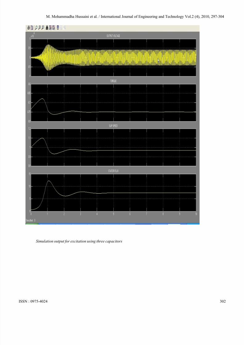
Simulation results:
ISSN : 0975-4024 301
Simulation output for excitation using three capacitors
By assuming current flows from converter to the ac system. X
8/3/2019 IJET Format Last Date Feb 10
http://slidepdf.com/reader/full/ijet-format-last-date-feb-10 6/8
M. Mohammadha Hussaini et al. / International Journal of Engineering and Technology Vol.2 (4), 2010, 297-304
Simulation output for excitation using three capacitors
ISSN : 0975-4024 302

8/3/2019 IJET Format Last Date Feb 10
http://slidepdf.com/reader/full/ijet-format-last-date-feb-10 7/8
M. Mohammadha Hussaini et al. / International Journal of Engineering and Technology Vol.2 (4), 2010, 297-304
Fig shows the smulation of SEIG with statcom
ISSN : 0975-4024 303
8/3/2019 IJET Format Last Date Feb 10
http://slidepdf.com/reader/full/ijet-format-last-date-feb-10 8/8
M. Mohammadha Hussaini et al. / International Journal of Engineering and Technology Vol.2 (4), 2010, 297-304
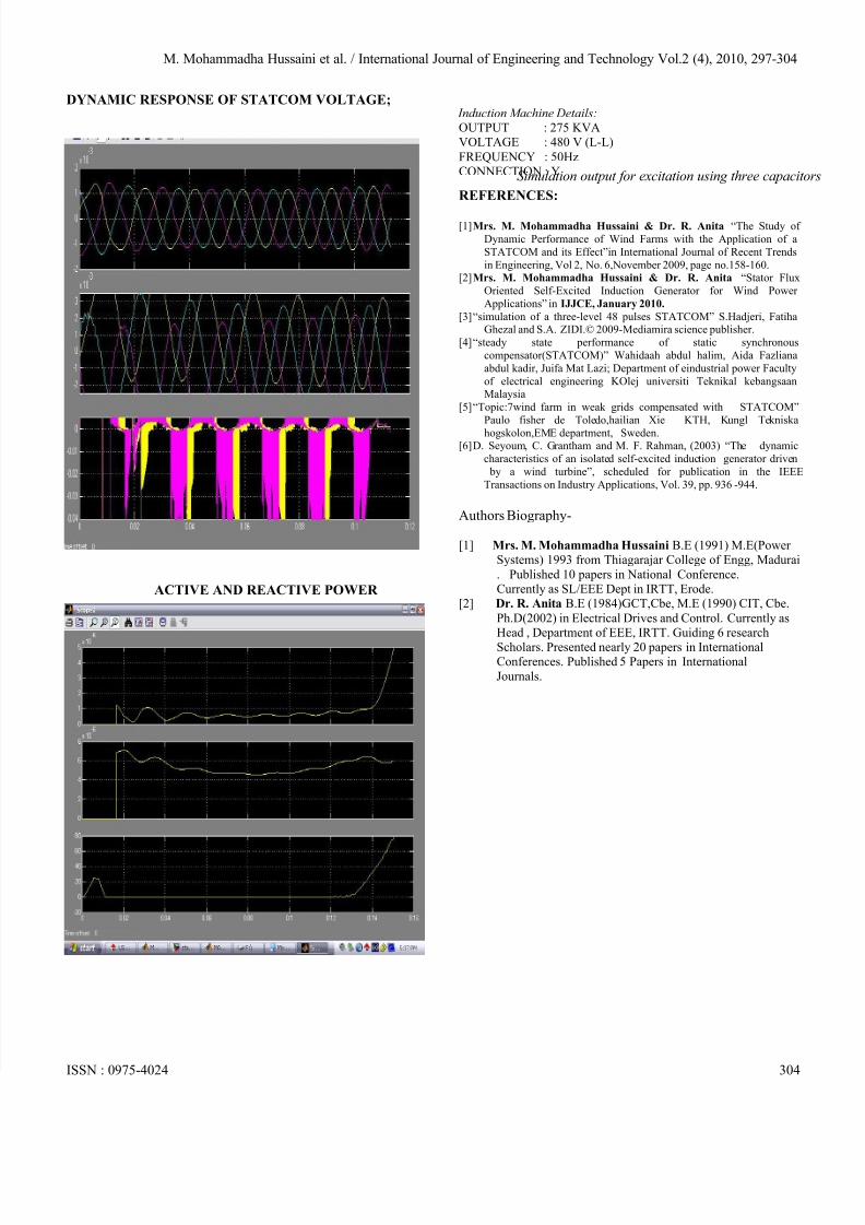
DYNAMIC RESPONSE OF STATCOM VOLTAGE;
ACTIVE AND REACTIVE POWER
Induction Machine Details:OUTPUT : 275 KVAVOLTAGE : 480 V (L-L)
FREQUENCY : 50HzCONNECTION : Y
REFERENCES:
[1] Mrs. M. Mohammadha Hussaini & Dr. R. Anita “The Study of
Dynamic Performance of Wind Farms with the Application of a
STATCOM and its Effect”in International Journal of Recent Trends
in Engineering, Vol 2, No. 6,November 2009, page no.158-160.[2] Mrs. M. Mohammadha Hussaini & Dr. R. Anita “Stator Flux
Oriented Self-Excited Induction Generator for Wind Power
Applications” in IJJCE, January 2010.
[3] “simulation of a three-level 48 pulses STATCOM” S.Hadjeri, FatihaGhezal and S.A. ZIDI.© 2009-Mediamira science publisher.
[4] “steady state performance of static synchronous
compensator(STATCOM)” Wahidaah abdul halim, Aida Fazliana
abdul kadir, Juifa Mat Lazi; Department of eindustrial power Faculty
of electrical engineering KOlej universiti Teknikal kebangsaanMalaysia
[5] “Topic:7wind farm in weak grids compensated with STATCOM”
Paulo fisher de Toledo,hailian Xie KTH, Kungl Tekniska
hogskolon,EME department, Sweden.[6] D. Seyoum, C. Grantham and M. F. Rahman, (2003) “The dynamic
characteristics of an isolated self-excited induction generator driven
by a wind turbine”, scheduled for publication in the IEEE
Transactions on Industry Applications, Vol. 39, pp. 936 -944.
Authors Biography-
[1] Mrs. M. Mohammadha Hussaini B.E (1991) M.E(Power Systems) 1993 from Thiagarajar College of Engg, Madurai
. Published 10 papers in National Conference.Currently as SL/EEE Dept in IRTT, Erode.
[2] Dr. R. Anita B.E (1984)GCT,Cbe, M.E (1990) CIT, Cbe.
Ph.D(2002) in Electrical Drives and Control. Currently asHead , Department of EEE, IRTT. Guiding 6 research
Scholars. Presented nearly 20 papers in InternationalConferences. Published 5 Papers in International
Journals.
ISSN : 0975-4024 304
Simulation output for excitation using three capacito


![[IJET-V2I1P11] Authors:Galal Ali Hassaan](https://img.pdfslide.us/doc/110x75/58ef54201a28abda518b457d/ijet-v2i1p11-authorsgalal-ali-hassaan.jpg)
![[IJET-V1I5P4] Authors :Murugan, Avudaiappan, Balasubramanian](https://img.pdfslide.us/doc/110x75/563db8c0550346aa9a9693f4/ijet-v1i5p4-authors-murugan-avudaiappan-balasubramanian.jpg)
![[IJET V2I5P17] Authors: S.AnnapurnaDevi, P. Ramesh Kumar](https://img.pdfslide.us/doc/110x75/587096461a28ab412b8b6857/ijet-v2i5p17-authors-sannapurnadevi-p-ramesh-kumar.jpg)
![[IJET-V1I3P7] Authors : Prateek Joshi, Mohammad UmairZaki](https://img.pdfslide.us/doc/110x75/55cf8e16550346703b8e6a9b/ijet-v1i3p7-authors-prateek-joshi-mohammad-umairzaki.jpg)
![[IJET V2I3P4] Authors: Manjunath Aski, Prathibha P](https://img.pdfslide.us/doc/110x75/588035781a28ab9f0f8b7319/ijet-v2i3p4-authors-manjunath-aski-prathibha-p.jpg)
![[IJET V2I4P3] Authors: N.Keerthi, N.Deepthi,N.Jaya Krishna](https://img.pdfslide.us/doc/110x75/5880354e1a28ab9f0f8b7277/ijet-v2i4p3-authors-nkeerthi-ndeepthinjaya-krishna.jpg)
![[IJET-V2I1P6] Authors:](https://img.pdfslide.us/doc/110x75/58ed96711a28ab78348b46d5/ijet-v2i1p6-authors.jpg)
![[IJET V2I5P22] Authors: Gangasani Ravikumar Reddy, M.Suneetha](https://img.pdfslide.us/doc/110x75/587096461a28ab412b8b684d/ijet-v2i5p22-authors-gangasani-ravikumar-reddy-msuneetha.jpg)

![[IJET-V1I6P21] Authors : Easwari.N , Ponmuthuramalingam.P](https://img.pdfslide.us/doc/110x75/587096431a28ab412b8b6847/ijet-v1i6p21-authors-easwarin-ponmuthuramalingamp.jpg)

![[IJET V2I4P8] Authors: Anju.S, Achu Govind K R](https://img.pdfslide.us/doc/110x75/588035591a28ab9f0f8b72c3/ijet-v2i4p8-authors-anjus-achu-govind-k-r.jpg)
![[IJET V2I4P1] Authors:Dashrath Singh Kathait](https://img.pdfslide.us/doc/110x75/587385891a28ab272d8b5af1/ijet-v2i4p1-authorsdashrath-singh-kathait.jpg)
![[IJET V2I5P4] Authors: Rachana Chavan, Rakesh Singh Lodhi](https://img.pdfslide.us/doc/110x75/587496f91a28abfc5f8b497b/ijet-v2i5p4-authors-rachana-chavan-rakesh-singh-lodhi.jpg)
![[IJET V2I3P6] Authors: Ajeeth, Sandhya raani M](https://img.pdfslide.us/doc/110x75/58ef9ccd1a28abbb588b456d/ijet-v2i3p6-authors-ajeeth-sandhya-raani-m.jpg)
![[IJET V2I5P2] Authors:Galal Ali Hassaan](https://img.pdfslide.us/doc/110x75/587671c91a28abd0018b63f3/ijet-v2i5p2-authorsgalal-ali-hassaan.jpg)
![[IJET V2I3P5] Authors: Jamuna H G, Shobha Hugar](https://img.pdfslide.us/doc/110x75/58ed96711a28ab78348b46e1/ijet-v2i3p5-authors-jamuna-h-g-shobha-hugar.jpg)
![[IJET V2I5P23] Authors:Pramod Kumar](https://img.pdfslide.us/doc/110x75/587096461a28ab412b8b684b/ijet-v2i5p23-authorspramod-kumar.jpg)
![[IJET V2I5P15] Authors: V.Preethi, G.Velmayil](https://img.pdfslide.us/doc/110x75/587096461a28ab412b8b685b/ijet-v2i5p15-authors-vpreethi-gvelmayil.jpg)
![[IJET V2I3P9] Authors: Ruchi Kumari , Sandhya Tarar](https://img.pdfslide.us/doc/110x75/588aab5e1a28ab4c308b6275/ijet-v2i3p9-authors-ruchi-kumari-sandhya-tarar.jpg)
![[IJET V2I5P7] Authors: Mr. Vaibhav A. Kalhapure, Dr.R.R.Navthar](https://img.pdfslide.us/doc/110x75/5883d1b41a28abb7308b6a4b/ijet-v2i5p7-authors-mr-vaibhav-a-kalhapure-drrrnavthar.jpg)
![[IJET V2I4P2] Authors:Damanbir Singh, Guneet Kaur](https://img.pdfslide.us/doc/110x75/58edce381a28abb4318b4641/ijet-v2i4p2-authorsdamanbir-singh-guneet-kaur.jpg)
![[IJET-V1I4P10] Authers :EiEi Thwe, Theingi](https://img.pdfslide.us/doc/110x75/55cf8559550346484b8d137f/ijet-v1i4p10-authers-eiei-thwe-theingi-55d475671ddfa.jpg)
![[IJET-V2I1P2] Authors: S. Lakshmi Prabha1, A.R.Mohamed Shanavas](https://img.pdfslide.us/doc/110x75/58ed968f1a28abec3c8b4615/ijet-v2i1p2-authors-s-lakshmi-prabha1-armohamed-shanavas.jpg)
![[IJET V2I2P27] Authors: Shruti Kamatekar, Prof. Balachandra G.C](https://img.pdfslide.us/doc/110x75/58edce701a28ab6f408b45cd/ijet-v2i2p27-authors-shruti-kamatekar-prof-balachandra-gc.jpg)
![[IJET V2I5P21] Authors: SIRGIREDDY CHINNAANKI REDDY, N.KEERTHI](https://img.pdfslide.us/doc/110x75/587096461a28ab412b8b684f/ijet-v2i5p21-authors-sirgireddy-chinnaanki-reddy-nkeerthi.jpg)
![[IJET-V2I2P7] Authors:Madhumitha J, Priyadarshini D, Soorya Ramchandran](https://img.pdfslide.us/doc/110x75/587095f01a28ab412b8b679f/ijet-v2i2p7-authorsmadhumitha-j-priyadarshini-d-soorya-ramchandran.jpg)
![[IJET-V1I3P9] Authors :Velu.S, Baskar.K, Kumaresan.A, Suruthi.K](https://img.pdfslide.us/doc/110x75/55cf8cb75503462b138f2c41/ijet-v1i3p9-authors-velus-baskark-kumaresana-suruthik-55fafbdeb8507.jpg)