Embed Size (px)
Citation preview

1
2
Govt. College of Technology Burewala
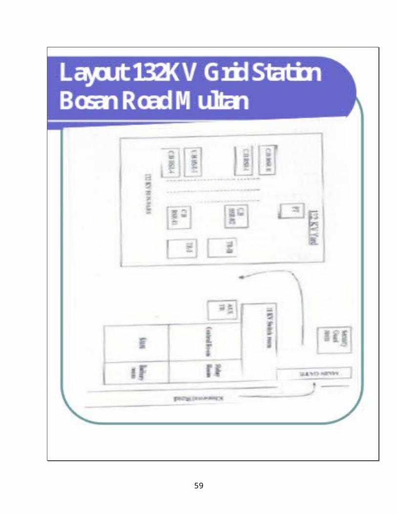
Project Training Report132kv Grid Station Bosan Road Multan.
B-Tech (Pass) Electrical Industrial Training Program
Session 2007-2009
Affiliated With
Training Supervisor Incharge B-Tech (Pass) Electrical
Sig. Sig. Muhammad Tariq Khurshid Sb. Mr. Amir Gafoor Sb. Incharge Head of Department 132kv Grid Station MEPCO B-Tech (Pass) Electrical Bosan Road Multan. G.C.T. Burewala.
Industrial Training Officer
Trainee Student
3
Sig. Sig.Mr. Ghulam Abbas Sb Muhammad Shoaib Saleem B-Tech (Pass) Electrical B-Tech (Pass) Electrical G.C.T. Burewala. University Roll# 31
Introduction
The present day electrical power system is a.c. i.e. electric
power is generated, transmitted and distributed in the form of
Alternating current. The electric power is produce at the power station,
which are located at favorable places, generally quite away from the
consumers. It is delivered to the consumer through a large network of
transmission and distribution. At many place in the line of power
system, it may be desirable and necessary to change some
characteristic ( e.g. Voltage, ac to de, frequency p.f. etc.) of electric
supply. This is accomplished by suitable apparatus called sub-station
for example, generation voltage (11kv or 6.6kv) at the power station is
stepped up to high voltage (Say 220kv to 132kv) for transmission of
electric power. Similarly near the consumer’s localities, the voltage may
have to be stepped down to utilization level. This job is again
accomplished by suitable apparatus called sub-station.
Definition of sub-station :-
4
“The assembly of apparatus used to change some
characteristics (e.g. Voltage al to de freq. p.f. etc) of electric supply is
called sub-station”.
Classification of sub-station
There are several ways of classifying sub-station. However the two
most important way of classifying them are.
I) According to service requirement :-
According to service requirement sub-station may be
classified into.
1) Transformer sub-station :-
Those sub-station which change the voltage level of
electrical supply are called TIF s/s.
2) Switching sub-station :-
These sub-station simply perform the switching operation of
power line.
3) Power factor correction S/S :-
These sub-station which improve the p.f. of the
system are called p.f. correction s/s. these are generally located at
receiving end s/s.
4) Frequency changer S/S :-
Those sub-stations, which change the supply frequency, are
known as frequency changer s/s. Such s/s may be required for industrial
utilization.
5) Converting sub-station :-
5
Those sub-station which change a.c. power into d.c. power
are called converting s/s ignition is used to convert AC to dc power for
traction, electroplating, electrical welding etc.
6) Industrial sub-station :-
Those sub-stations, which supply power to individual industrial concerns,
are known as industrial sub-station.
II) According to constructional features :-
According to constructional features, the sub-station are
classified as :
1) Outdoor Sub-Station :-
For voltage beyond 66KV, equipment is invariably installed
outdoor. It is because for such Voltage the clearances between
conductor and the space required for switches, C.B. and other
equipment becomes so great that it is not economical to installed the
equipment indoor.
2) Indoor Sub-station :-
For voltage up to 11KV, the equipment of the s/s is installed
indoor because of economic consideration. However, when the
atmosphere is contaminated with impurities, these sub-stations can be
erected for voltage up to 66KV.
3) Under ground sub-station :-
In thickly populated areas, the space available for
equipment and building is limited and the cost of the land is high.
Under such situations, the sub-station is created underground.
6
Fig. Shows a typical underground sub-station in which
transformer, switch gear & other equipments are installed.
The design of underground s/s requires more careful consideration
1) The size of the s/s should be as minimum as possible.
2) There should be responsible access for both equipment & personal.
3) There should be provision for emergency lighting and protection
against fire.
There should be good ventilation
4) Pole-mounted sub-station :-
This is an outdoor sub-station with equipment installed
overhead on H.pole or 4-pole structure. It is the cheapest from of s/s for
voltage not exceeding 11KV(or 33KV in some cases). Electric power is
almost distributed in localities through such sub-station. For complete
is given bellow.
Fig. Shows the typical 4-pole sub-station, it is a distribution
sub-station placed overhead on a pole. Fig No.2 shows the schematic
connections, the transformer & other equipment are mounted on H-type
pole.
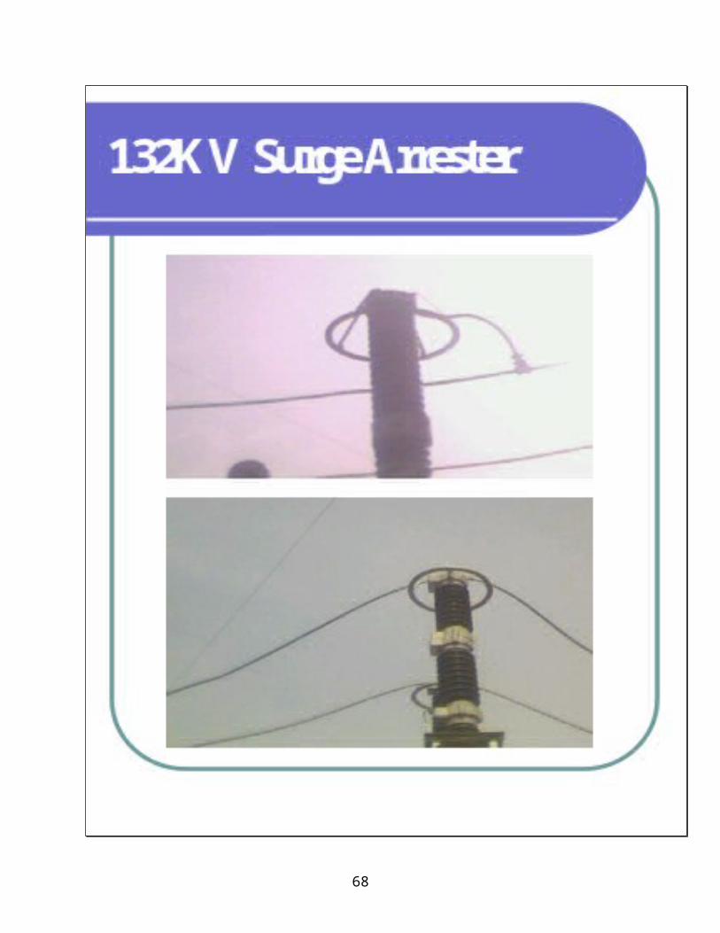
The 11KV line is connected to the T/F (11KV/440V) through
gang isolator and fuses. The lighting arresters are installed on the H.T.
Side to protect the sub-station from lighting strokes. The T/F step down
voltage to 400 V, 3 phase, 4 wire supply. The voltage between any two
lines is 400 V & between line & neutral is 230V. The oil ckt breaker
installed on the L.T. side automatically isolates the mounted sub-station.
T/F are generally in the event of fault generally 200KVA T/F is used.
7
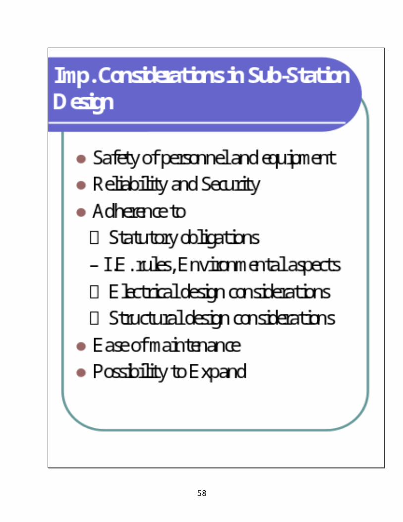
Functions of a Substation:1 - Supply of required electrical power. 2 - Maximum possible coverage of the supply network. 3 - Maximum security of supply. 4 - Shortest possible fault-duration. 5 - Optimum efficiency of plants and the network. 6 - Supply of electrical power within targeted frequency limits, (49.5 Hz and 50.5 Hz). 7 - Supply of electrical power within specified voltage limits. 8 - Supply of electrical energy to the consumers at the lowest cost.
Equipment Used in a Sub-Station
The equipment required for a transformer Sub-Station depends upon the
type of Sub-Station, Service requirement and the degree of protection
desired. TIF Sub-Station has the following major equipments.
1) Bus - bar :-
When a no. of lines operating at the same voltage have to
be directly connected electrically, bus-bar are used, it is made up of
copper or aluminum bars (generally of rectangular X-Section) and
operate at constant voltage.
Fig. Shows the arrangement of Duplicate bus-bar, generally
it consist of two bus-bars a “main” bus-bar and spare bus-bar. The
incoming and outgoing lines can be connected to either b/b. With the
help of a bus-bar coupler, which consist of a ckt breaker and isolators.
However, in case of repair of main bus-bar or fault accusing
on it, the continuity of supply to the circuit can be maintain by
transforming it to the spare bus-bar for voltage exceeding 33KV,
Duplicate bus-bar is frequently used.
2) Insulators :-
8
The insulator serves two purpose. They support the
conductor ( or bus bar ) and confine the current to the conductor. The
most commonly used material for the manufactures of insulators is
porcelain. There are several type of insulator (i.e. pine type, suspension
type etc.) and there used in Sub-Station will depend upon the service
requirement.
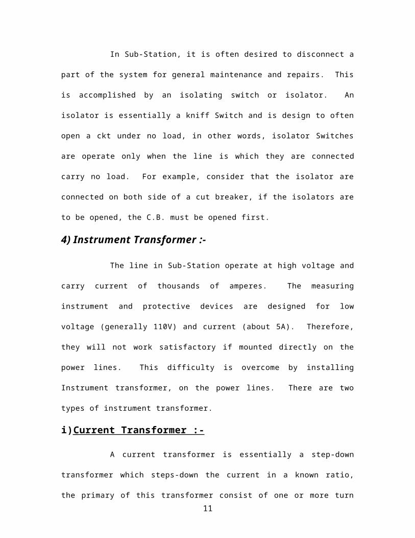
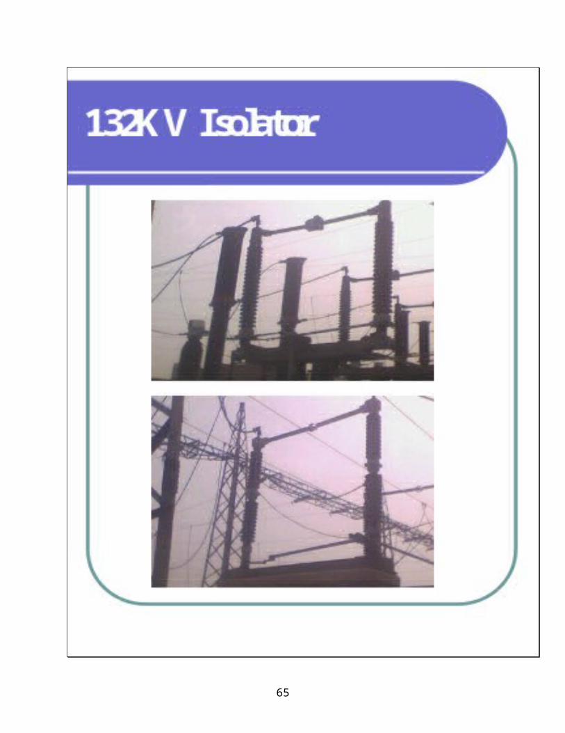
3) Isolating Switches :-
In Sub-Station, it is often desired to disconnect a part of the
system for general maintenance and repairs. This is accomplished by
an isolating switch or isolator. An isolator is essentially a kniff Switch
and is design to often open a ckt under no load, in other words, isolator
Switches are operate only when the line is which they are connected
carry no load. For example, consider that the isolator are connected on
both side of a cut breaker, if the isolators are to be opened, the C.B.
must be opened first.
4) Instrument Transformer :-
The line in Sub-Station operate at high voltage and carry
current of thousands of amperes. The measuring instrument and
protective devices are designed for low voltage (generally 110V) and
current (about 5A). Therefore, they will not work satisfactory if mounted
directly on the power lines. This difficulty is overcome by installing
Instrument transformer, on the power lines. There are two types of
instrument transformer.
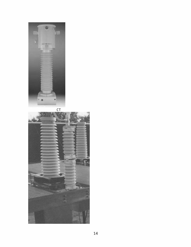
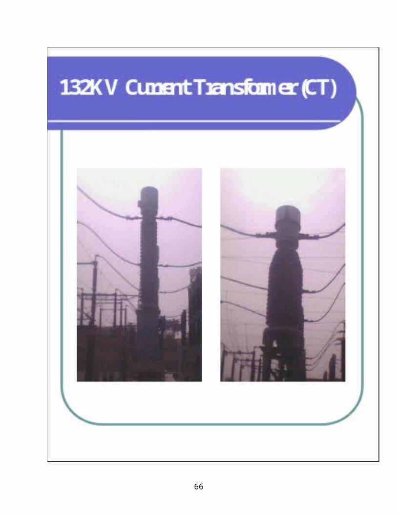
i) Current Transformer :-
9
A current transformer is essentially a step-down transformer
which steps-down the current in a known ratio, the primary of this
transformer consist of one or more turn of thick wire connected in series
with the line, the secondary consist of thick wire connected in series
with line having large number of turn of fine wire and provides for
measuring instrument, and relay a current which is a constant faction of
the current in the line.
The current transformer (CT) is often treated as a ‘‘black box.’’ It is a transformer that is governed by thelaws of electromagnetic induction:
ε = k β Ac NfWhere ε = Induced voltage β = Flux densityAc = Core cross-sectional areaN = Turnsf = Frequency k = Constant of proportionality
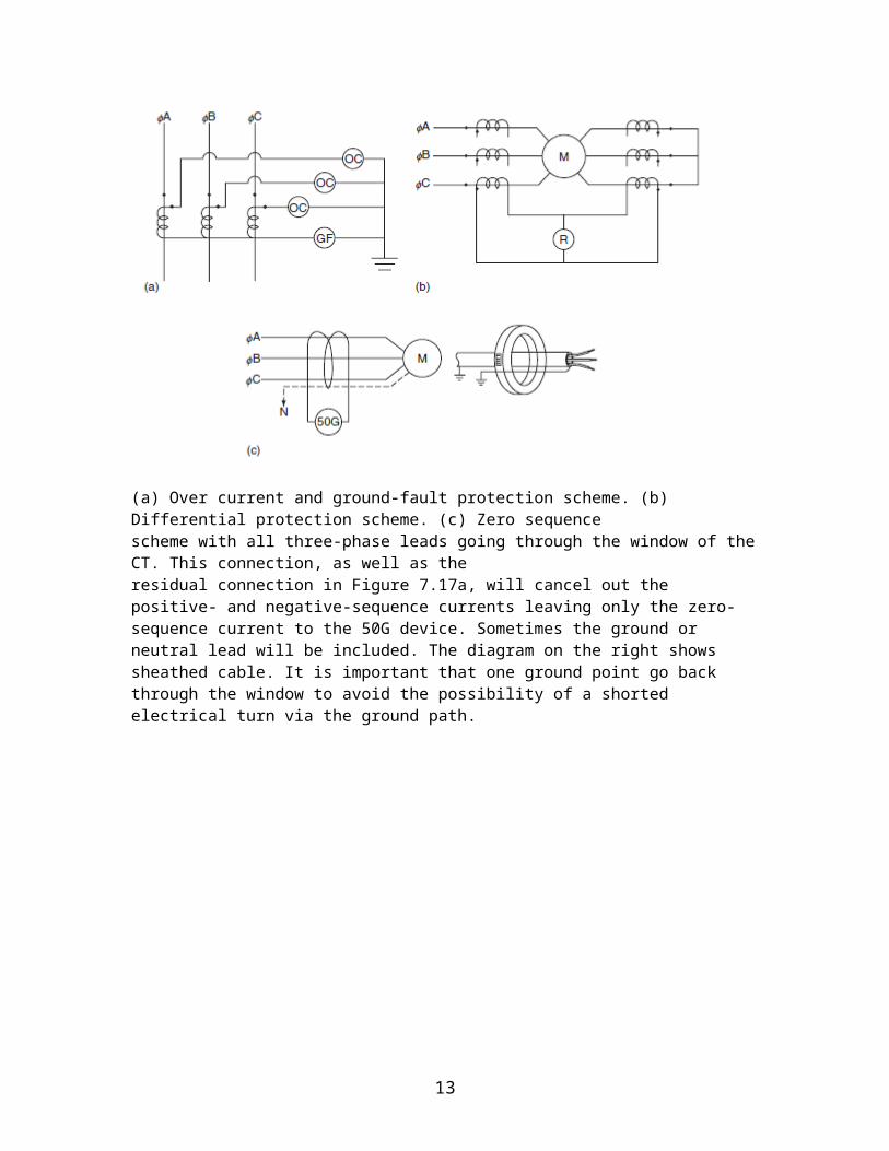
CT Connections:As previously mentioned, some dev ices are sensitive to the direction of current flow. It is often critical inthree-phase schemes to maintain proper phase shifting . Residually connected CTs in three-phaseground-fault scheme sum to zero when the phases are balanced. Reversed polarity of aCT could cause a ground-fault relay to trip under a normal balanced condition. Another scheme todetect zero-sequence faults uses one CT to simultaneously monitor all leads and neutral. In differential protection schemes current-source phase and magnitude are compared. Reverse polarity of a CT could effectively double the phase current flowing into the relay, thus causing a nuisance tripping of a relay. When two CTs are driving a three-phase ammeter through a switch, a reversed CT could show 1.73 times the monitored current flowing in the unmonitored circuit.
10
(a) Over current and ground-fault protection scheme. (b) Differential protection scheme. (c) Zero sequencescheme with all three-phase leads going through the window of the CT. This connection, as well as theresidual connection in Figure 7.17a, will cancel out the positive- and negative-sequence currents leaving only the zero-sequence current to the 50G device. Sometimes the ground or neutral lead will be included. The diagram on the right shows sheathed cable. It is important that one ground point go back through the window to avoid the possibility of a shorted electrical turn via the ground path.
11

CT
12
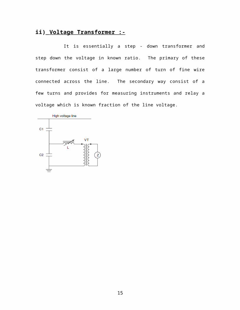
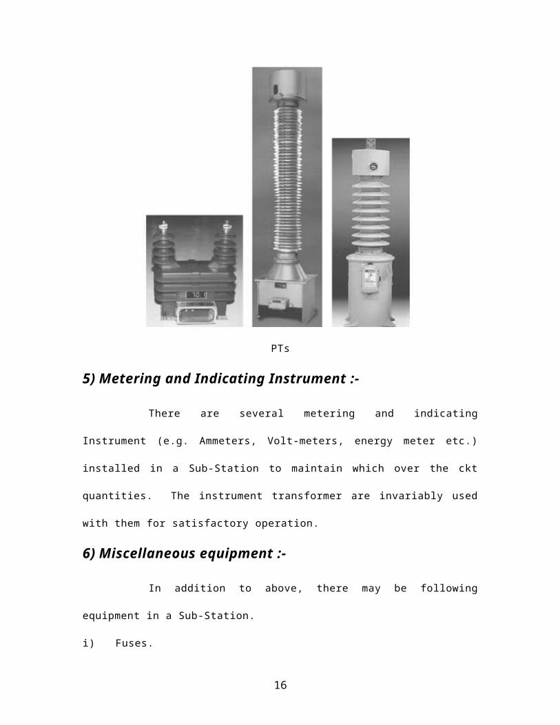
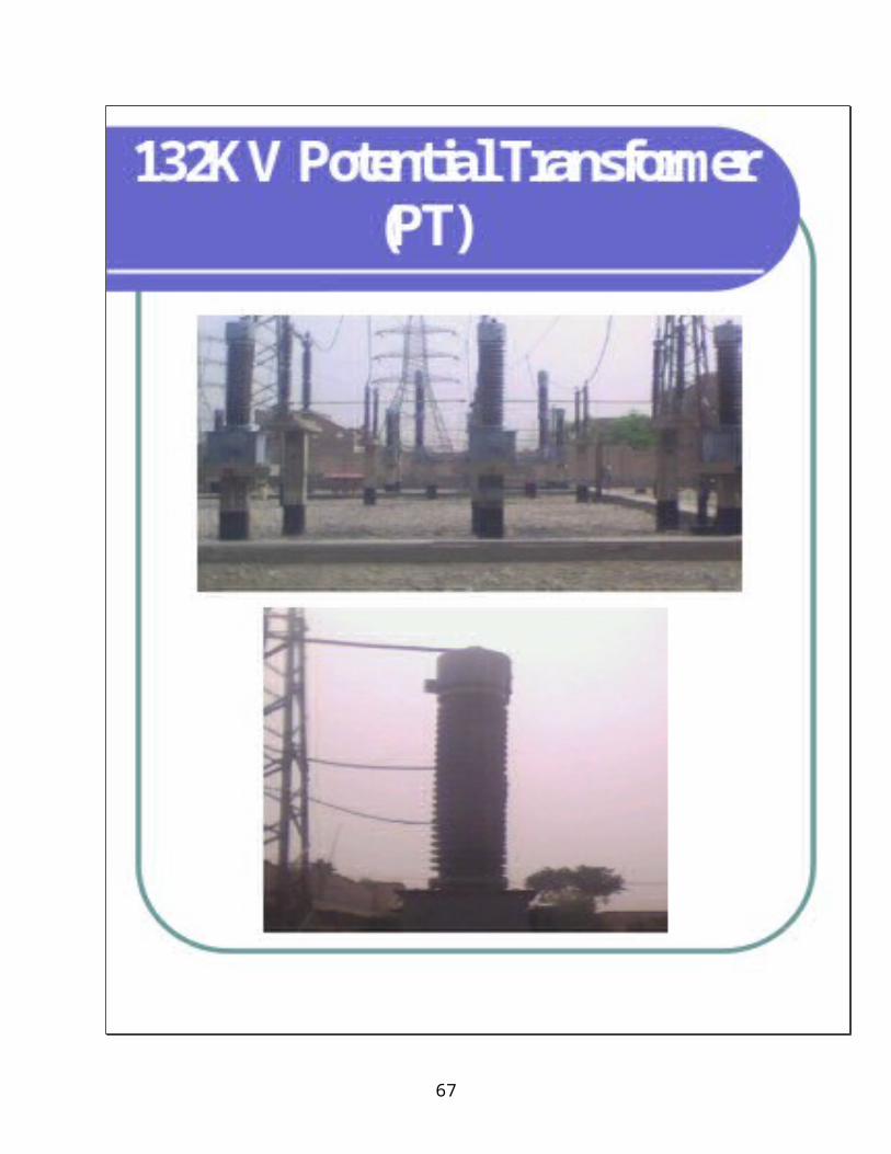
ii) Voltage Transformer :-
It is essentially a step - down transformer and step down the
voltage in known ratio. The primary of these transformer consist of a
large number of turn of fine wire connected across the line. The
secondary way consist of a few turns and provides for measuring
instruments and relay a voltage which is known fraction of the line
voltage.
PTs
13
5) Metering and Indicating Instrument :-
There are several metering and indicating Instrument (e.g.
Ammeters, Volt-meters, energy meter etc.) installed in a Sub-Station to
maintain which over the ckt quantities. The instrument transformer are
invariably used with them for satisfactory operation.
6) Miscellaneous equipment :-
In addition to above, there may be following equipment in a
Sub-Station.
i) Fuses.
ii) Carrier-current equipment.
iii) Sub-Station auxiliary supplies.
7) Protective relay :-
“A protective relay is a device that detects the fault and
initiates the operation of the C.B. to isolate the defective element from
the rest of the system”. The relay detects the abnormal condition in the
electrical ckt by constantly measuring the electrical quantities, which
are different under normal and fault condition. The electrical quantities
which may change under fault condition are voltage, current, frequency
and phase angle. Having detect the fault, the relay operate to close the
trip ckt of C.B.
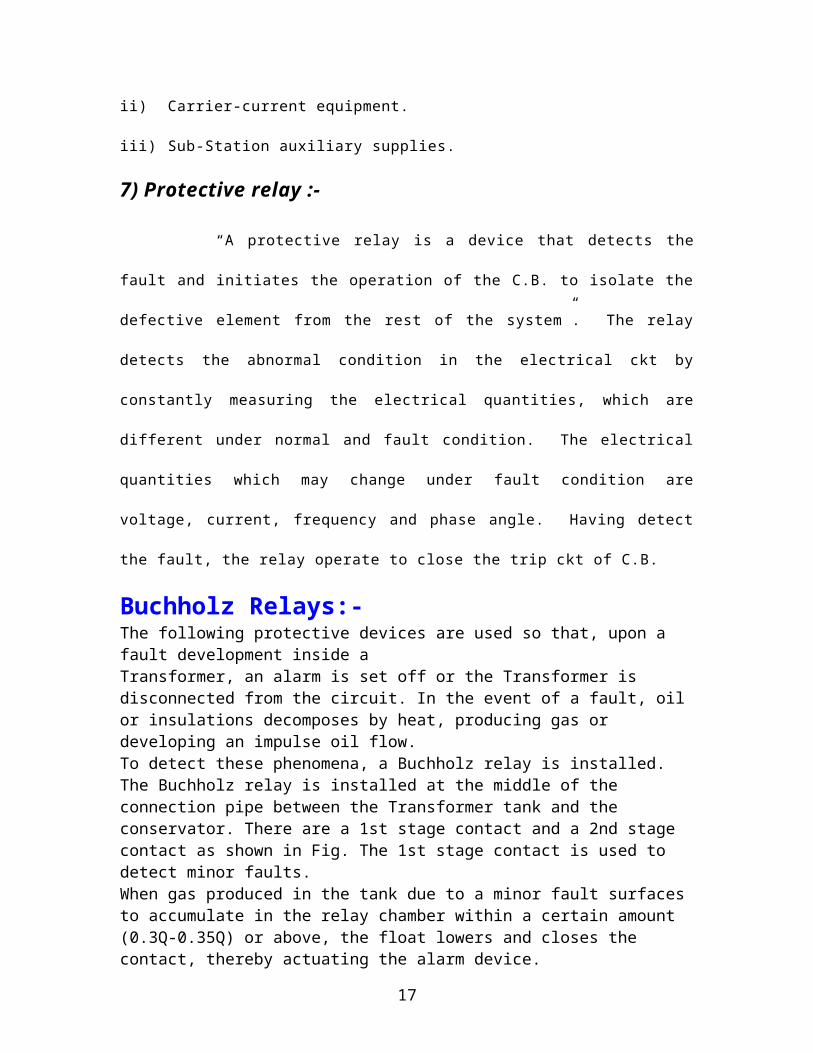
Buchholz Relays:-The following protective devices are used so that, upon a fault development inside a Transformer, an alarm is set off or the Transformer is disconnected from the circuit. In the event of a fault, oil or insulations decomposes by heat, producing gas or developing an impulse oil flow. To detect these phenomena, a Buchholz relay is installed. The Buchholz relay is installed at the middle of the connection pipe
14
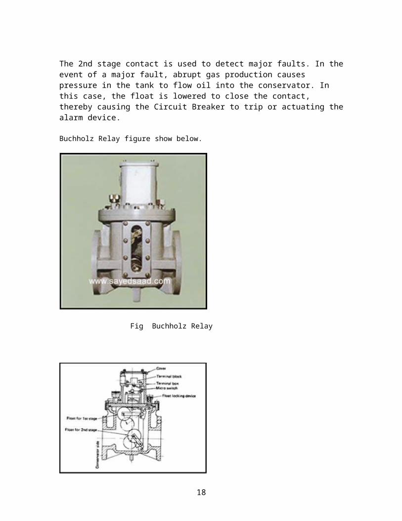
between the Transformer tank and the conservator. There are a 1st stage contact and a 2nd stage contact as shown in Fig. The 1st stage contact is used to detect minor faults. When gas produced in the tank due to a minor fault surfaces to accumulate in the relay chamber within a certain amount (0.3Q-0.35Q) or above, the float lowers and closes the contact, thereby actuating the alarm device.
The 2nd stage contact is used to detect major faults. In the event of a major fault, abrupt gas production causes pressure in the tank to flow oil into the conservator. In this case, the float is lowered to close the contact, thereby causing the Circuit Breaker to trip or actuating the alarm device.
Buchholz Relay figure show below.
Fig Buchholz Relay
15
Structure of Buchholz Relay
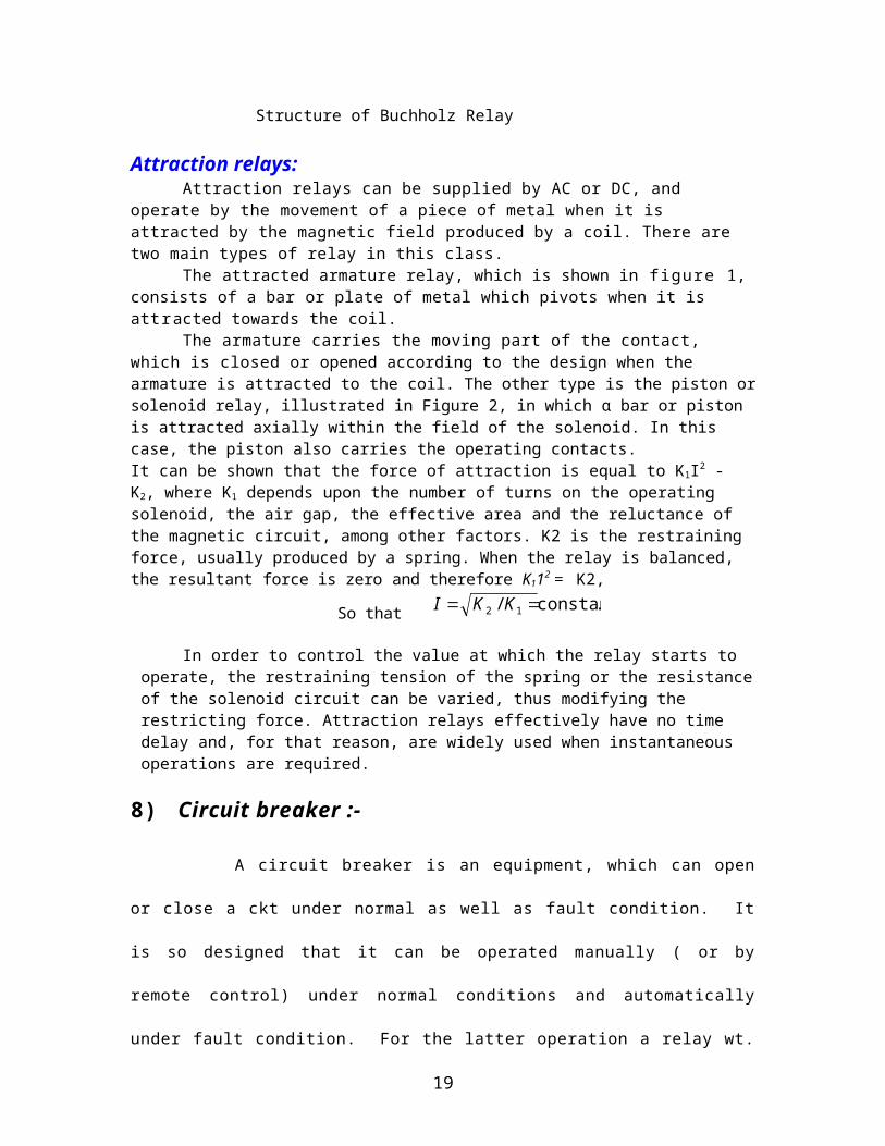
Attraction relays:Attraction relays can be supplied by AC or DC, and operate by the
movement of a piece of metal when it is attracted by the magnetic field produced by a coil. There are two main types of relay in this class.
The attracted armature relay, which is shown in figure 1, consists of a bar or plate of metal which pivots when it is attracted towards the coil.
The armature carries the moving part of the contact, which is closed or opened according to the design when the armature is attracted to the coil. The other type is the piston or solenoid relay, illustrated in Figure 2, in which α bar or piston is attracted axially within the field of the solenoid. In this case, the piston also carries the operating contacts.It can be shown that the force of attraction is equal to K1I2 - K2, where Κ1 depends upon the number of turns on the operating solenoid, the air gap, the effective area and the reluctance of the magnetic circuit, among other factors. K2 is the restraining force, usually produced by a spring. When the relay is balanced, the resultant force is zero and therefore Κ112 = K2,
So that .constant/ 12 KKI
In order to control the value at which the relay starts to operate, the restraining tension of the spring or the resistance of the solenoid circuit can be varied, thus modifying the restricting force. Attraction relays effectively have no time delay and, for that reason, are widely used when instantaneous operations are required.
8) Circuit breaker :-
A circuit breaker is an equipment, which can open or close a
ckt under normal as well as fault condition. It is so designed that it can
be operated manually ( or by remote control) under normal conditions
16
and automatically under fault condition. For the latter operation a relay
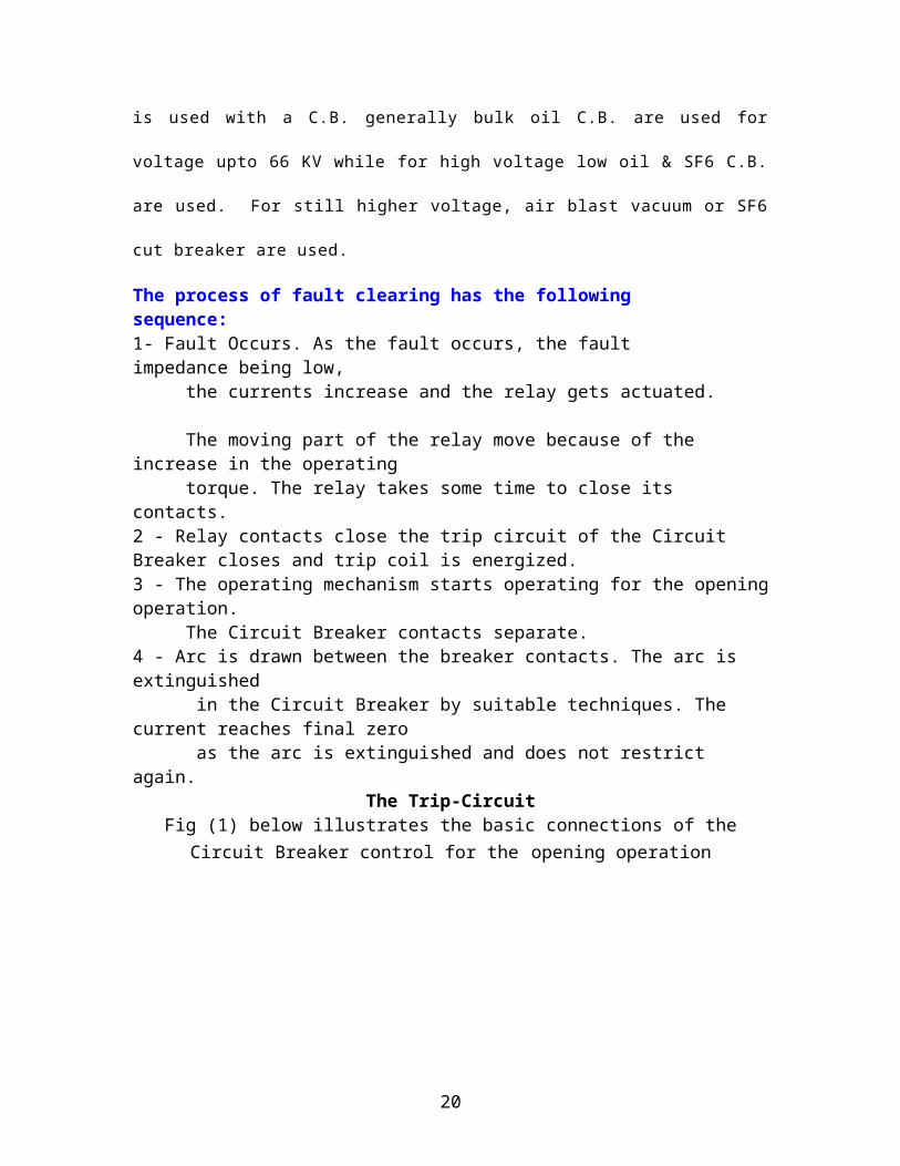
wt. is used with a C.B. generally bulk oil C.B. are used for voltage upto
66 KV while for high voltage low oil & SF6 C.B. are used. For still higher
voltage, air blast vacuum or SF6 cut breaker are used.
The process of fault clearing has the following sequence:1- Fault Occurs. As the fault occurs, the fault impedance being low, the currents increase and the relay gets actuated. The moving part of the relay move because of the increase in the operating torque. The relay takes some time to close its contacts.2 - Relay contacts close the trip circuit of the Circuit Breaker closes and trip coil is energized.3 - The operating mechanism starts operating for the opening operation. The Circuit Breaker contacts separate.4 - Arc is drawn between the breaker contacts. The arc is extinguished in the Circuit Breaker by suitable techniques. The current reaches final zero as the arc is extinguished and does not restrict again.
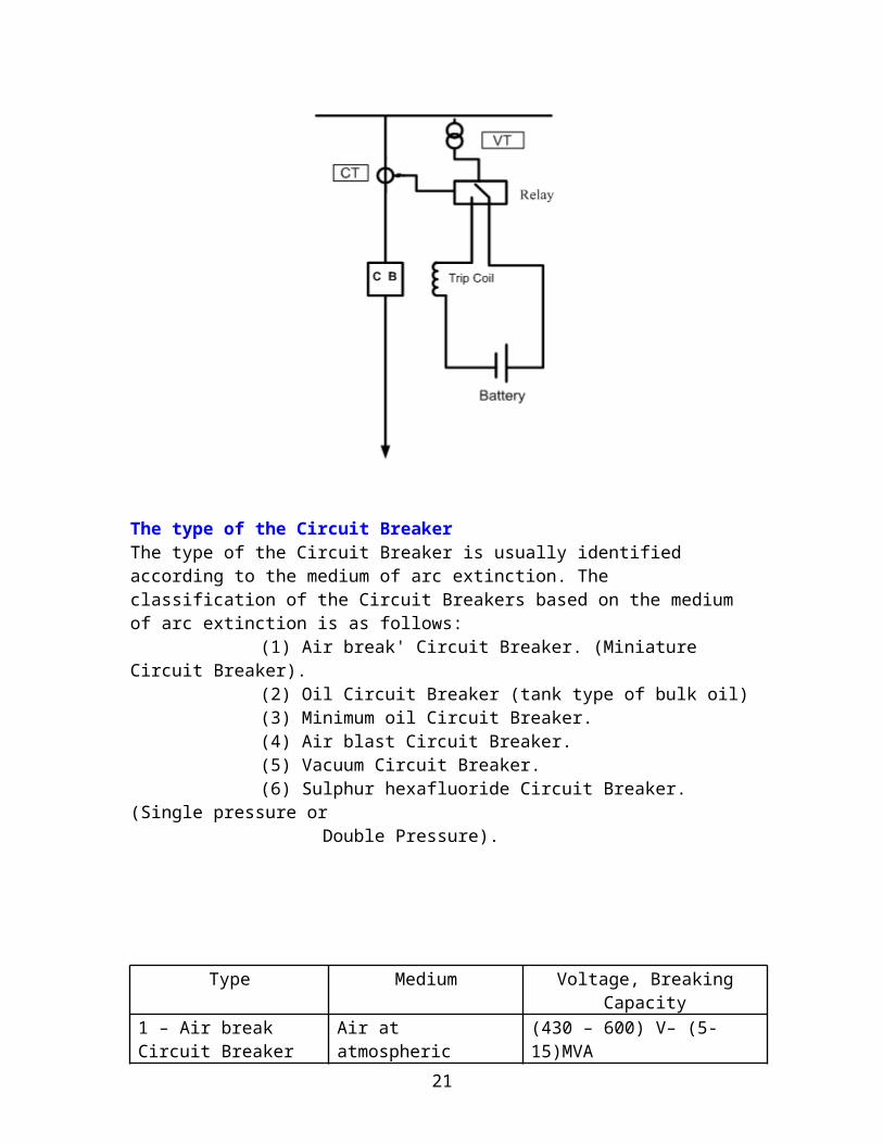
The Trip-CircuitFig (1) below illustrates the basic connections of the Circuit Breaker
control for the opening operation
17
The type of the Circuit BreakerThe type of the Circuit Breaker is usually identified according to the medium of arc extinction. The classification of the Circuit Breakers based on the medium of arc extinction is as follows:
(1) Air break' Circuit Breaker. (Miniature Circuit Breaker).
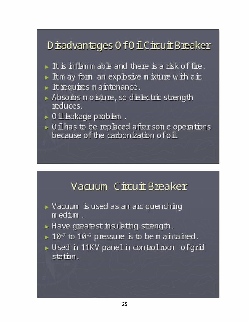
(2) Oil Circuit Breaker (tank type of bulk oil)(3) Minimum oil Circuit Breaker.(4) Air blast Circuit Breaker.(5) Vacuum Circuit Breaker.(6) Sulphur hexafluoride Circuit Breaker. (Single
pressure or Double Pressure).
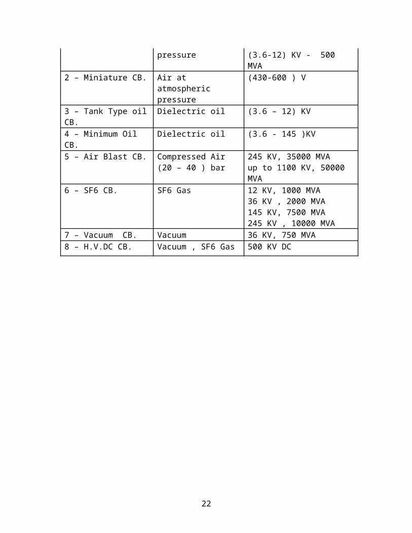
Type Medium Voltage, Breaking Capacity
1 – Air break Circuit Breaker
Air at atmospheric pressure
(430 – 600) V– (5-15)MVA(3.6-12) KV - 500 MVA
2 – Miniature CB. Air at atmospheric pressure
(430-600 ) V
3 – Tank Type oil CB. Dielectric oil (3.6 – 12) KV
4 – Minimum Oil CB. Dielectric oil (3.6 - 145 )KV5 – Air Blast CB. Compressed Air
(20 – 40 ) bar245 KV, 35000 MVAup to 1100 KV, 50000 MVA
6 – SF6 CB. SF6 Gas 12 KV, 1000 MVA36 KV , 2000 MVA145 KV, 7500 MVA 245 KV , 10000 MVA
7 – Vacuum CB. Vacuum 36 KV, 750 MVA 8 – H.V.DC CB. Vacuum , SF6 Gas 500 KV DC
18
19
20
21
22
23

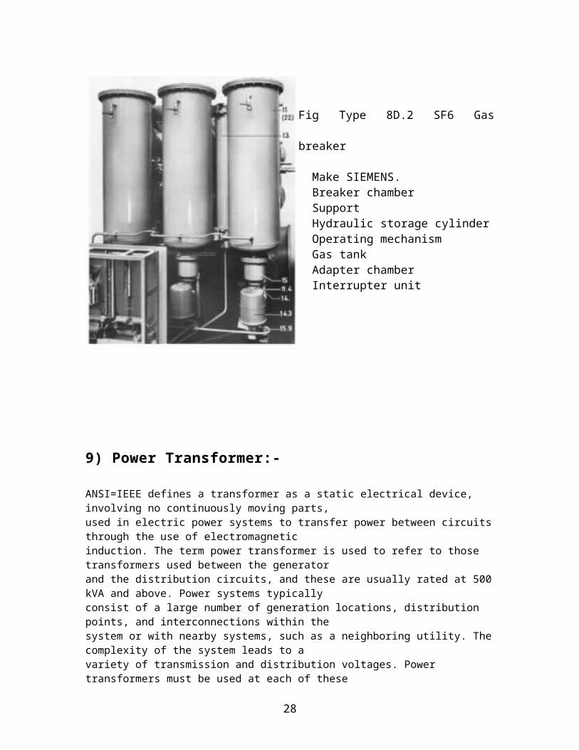
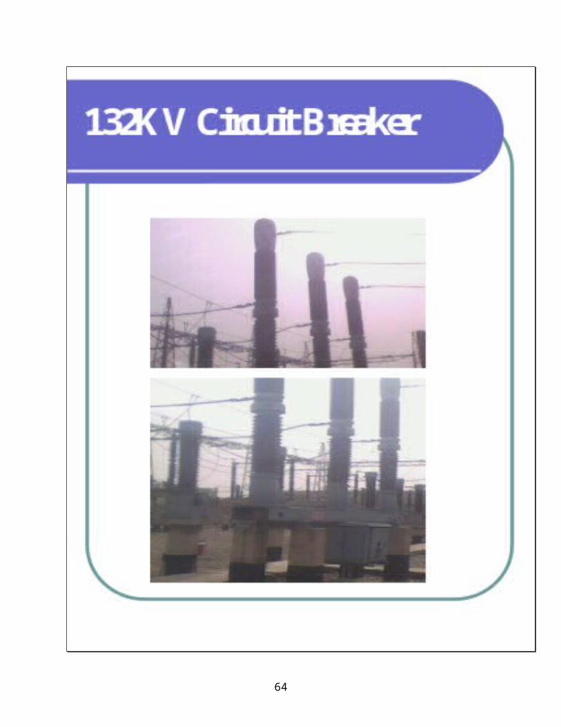
Fig Type 8D.2 SF6 Gas breaker
Make SIEMENS. Breaker chamber Support Hydraulic storage cylinder Operating mechanism Gas tank Adapter chamber Interrupter unit
9) Power Transformer:-
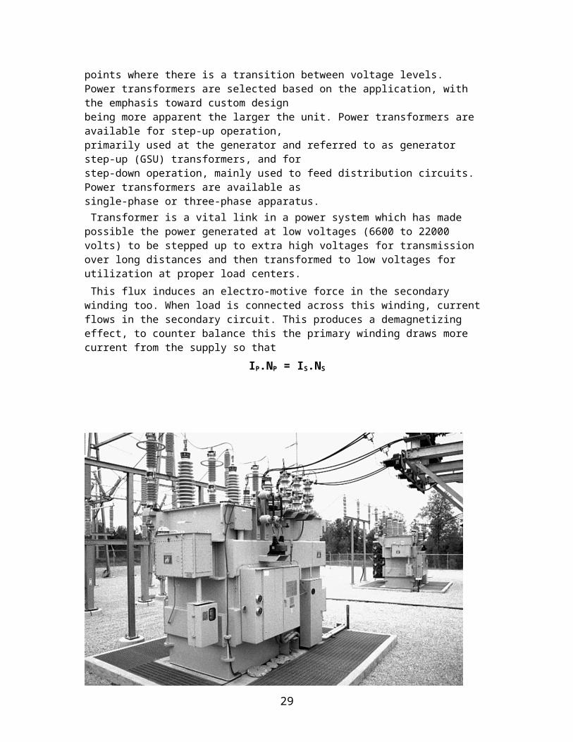
ANSI=IEEE defines a transformer as a static electrical device, involving no continuously moving parts,used in electric power systems to transfer power between circuits through the use of electromagneticinduction. The term power transformer is used to refer to those transformers used between the generatorand the distribution circuits, and these are usually rated at 500 kVA and above. Power systems typicallyconsist of a large number of generation locations, distribution points, and interconnections within thesystem or with nearby systems, such as a neighboring utility. The complexity of the system leads to avariety of transmission and distribution voltages. Power transformers must be used at each of thesepoints where there is a transition between voltage levels.Power transformers are selected based on the application, with the emphasis toward custom designbeing more apparent the larger the unit. Power transformers are available for step-up operation,primarily used at the generator and referred to as generator step-up (GSU) transformers, and forstep-down operation, mainly used to feed distribution circuits. Power transformers are available assingle-phase or three-phase apparatus.
24
Transformer is a vital link in a power system which has made possible the power generated at low voltages (6600 to 22000 volts) to be stepped up to extra high voltages for transmission over long distances and then transformed to low voltages for utilization at proper load centers.
This flux induces an electro-motive force in the secondary winding too. When load is connected across this winding, current flows in the secondary circuit. This produces a demagnetizing effect, to counter balance this the primary winding draws more current from the supply so that
IP.NP = IS.NS
Fig Power Transformer
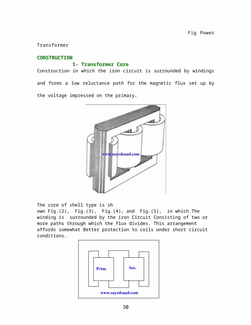
CONSTRUCTION 1- Transformer CoreConstruction in which the iron circuit is surrounded by windings and forms a
low reluctance path for the magnetic flux set up by the voltage impressed on
the primary.
25
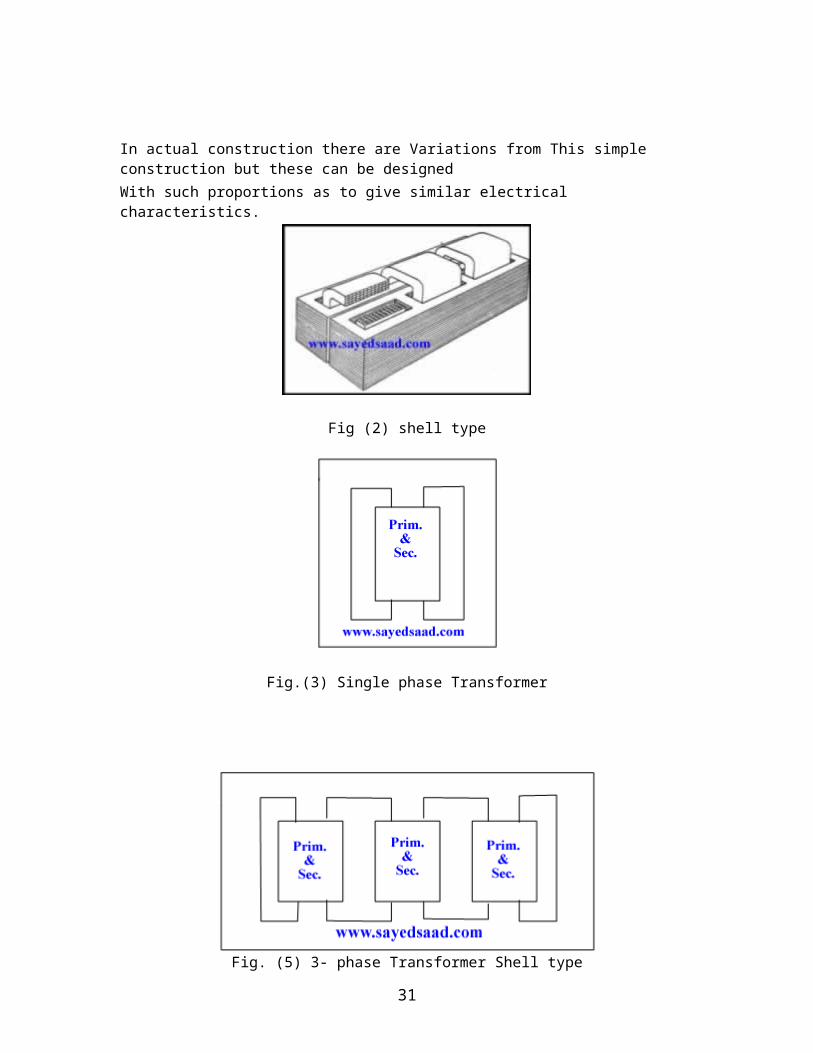
The core of shell type is shown Fig.(2), Fig.(3), Fig.(4), and Fig.(5), in which The winding is surrounded by the iron Circuit Consisting of two or more paths through which the flux divides. This arrangement affords somewhat Better protection to coils under short circuit conditions.
In actual construction there are Variations from This simple construction but these can be designed With such proportions as to give similar electrical characteristics.
Fig (2) shell type
26
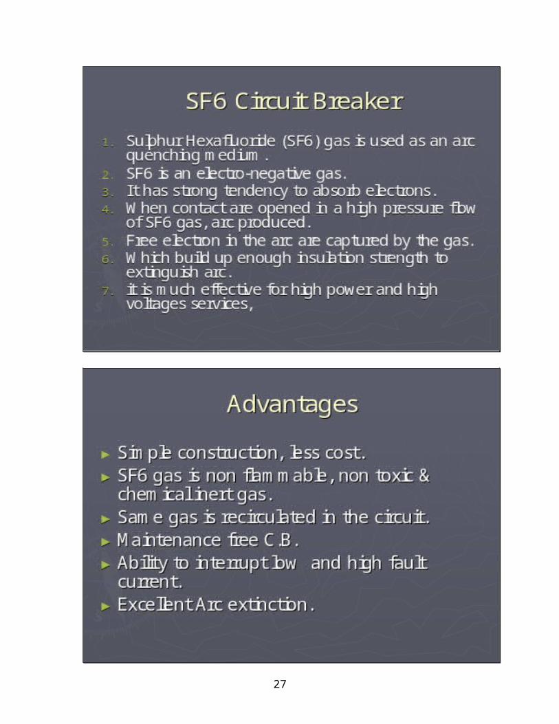
Fig.(3) Single phase Transformer
Fig. (5) 3- phase Transformer Shell type
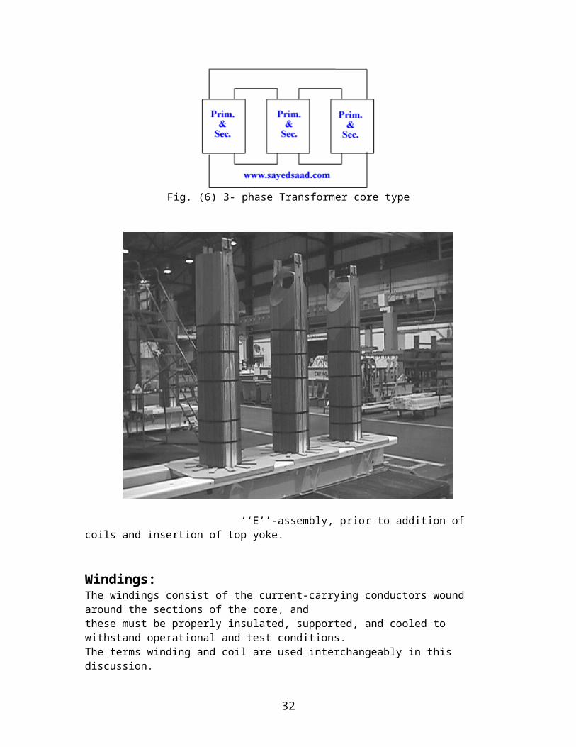
Fig. (6) 3- phase Transformer core type
27
‘‘E’’-assembly, prior to addition of coils and insertion of top yoke.
Windings:The windings consist of the current-carrying conductors wound around the sections of the core, andthese must be properly insulated, supported, and cooled to withstand operational and test conditions.The terms winding and coil are used interchangeably in this discussion.Copper and aluminum are the primary materials used as conductors in power-transformer windings.While aluminum is lighter and generally less expensive than copper, a larger cross section of aluminumconductor must be used to carry a current with similar performance as copper. Copper has highermechanical strength and is used almost exclusively in all but the smaller size ranges, where aluminumconductors may be perfectly acceptable. In cases where extreme forces are encountered, materials such assilver-bearing copper can be used for even greater strength. The conductors used in power transformersare t y pically stranded with a rectangular cross section, although some transformers at the lowest ratingsmay use sheet or foil conductors. Multiple strands can be wound in parallel and joined together at theends of the winding, in which case it is necessary to transpose the strands at various points throughout
28
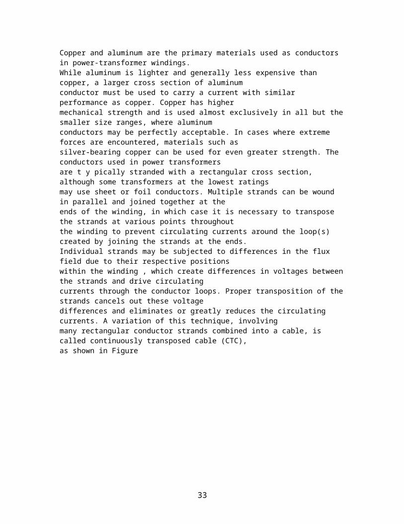
the winding to prevent circulating currents around the loop(s) created by joining the strands at the ends.Individual strands may be subjected to differences in the flux field due to their respective positionswithin the winding , which create differences in voltages between the strands and drive circulatingcurrents through the conductor loops. Proper transposition of the strands cancels out these voltagedifferences and eliminates or greatly reduces the circulating currents. A variation of this technique, involvingmany rectangular conductor strands combined into a cable, is called continuously transposed cable (CTC),as shown in Figure
Continuously transposed cable (CTC).
29
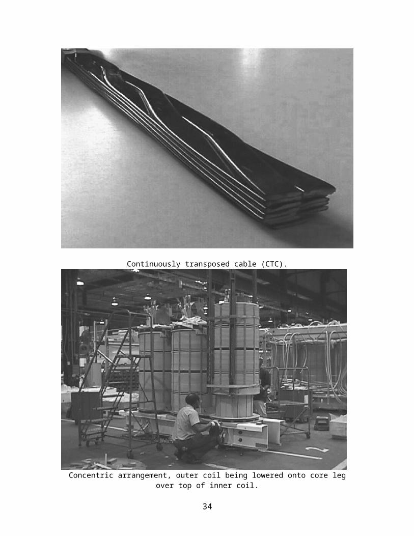
Concentric arrangement, outer coil being lowered onto core leg over top of inner coil.
A variety of different types of windings have been used in power transformers through the years. Coilscan be wound in an upright, vertical orientation, as is necessary with larger, heavier coils; or they can bewound horizontally and placed upright upon completion. As mentioned previously, the type of windingdepends on the transformer rating as well as the core construction. Several of the more commonwinding types are discussed here..Pancake WindingsSeveral types of windings are commonly referred to as ‘‘pancake’’ windings due to the arrangement ofconductors into discs. However, the term most often refers to a coil type that is used almost exclusivelyin shell-form transformers. The conductors are wound around a rectangular form, with the widest faceof the conductor oriented either horizontally or vertically. Figure 2.12 illustrates how these coils aretypically wound. This type of winding lends itself to the interleaved arrangement previously discussed.
30
Pancake winding during winding process.Layer (Barrel) Windings:Layer (barrel) windings are among the simplest of win dings in that the insulated conductors are wounddirectly next to each other around the cylinder and spacers. Several layers can be wound on top of oneanother, with the layers separated by solid insulation, ducts, or a combination. Several strands can bewound in parallel if the current magnitude so dictates. Variations of this win ding are often used forapplications such as tap windings used in load-tap-changing (LTC) transformers and for tertiarywindings used for, among other things, third-harmonic suppression. Figure shows a layer windingduring assembly that will be used as a regulating winding in an LTC transformer.
Stacked pancake windings.
31
Layer windings (single layer with two strands wound in parallel).Helical Windings:Helical windings are also referred to as screw or spiral windings, with each term accurately characterizingthe coil’s construction. A helical winding consists of a few to more than 100 insulated strands wound inparallel continuously along the length of the cylinder, with spacers inserted between adjacent turns ordiscs and suitable transpositions included to minimize circulating currents between parallel strands. Themanner of construction is such that the coil resembles a corkscrew. Figure 2.15 shows a helical windingduring the winding process. Helical windings are used for the higher-current applications frequentlyencountered in the lower-voltage classes.
Helical winding during assembly.
32
Tank:The tank has two main parts: a –The tank is manufactured by forming and welding steel plate to be used as a container for holding the core and coil assembly together with insulating oil.
The base and the shroud, over which a cover is sometimes bolted. These parts are manufactured in steel plates assembled together via weld beads. The tank is provided internally with devices usually made of wood for fixing the magnetic circuit and the windings. In addition, the tank is designed to withstand a total vacuum during the treatment process. Sealing between the base and shroud is provided by weld beads. The other openings are sealed with oil-resistant synthetic rubber joints, whose compression is limited by steel stops. Finally the tank is designed to withstand the application of the internal overpressure specified, without permanent deformation.
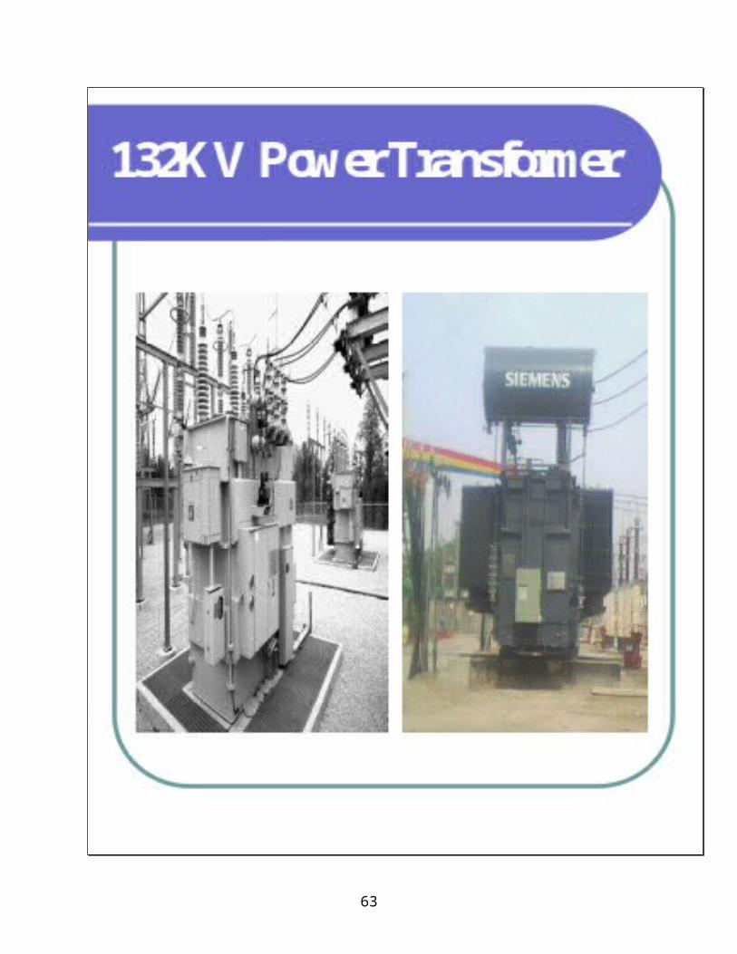
Fig Power Transformer 30 MVA 132 / 11 KV
Conservator:The tank is equipped with an expansion reservoir (conservator) which allows for the expansion of the oil during operation. The conservator is designed to hold a total vacuum and may be equipped with a rubber membrane preventing direct contact between the oil and the air.
33
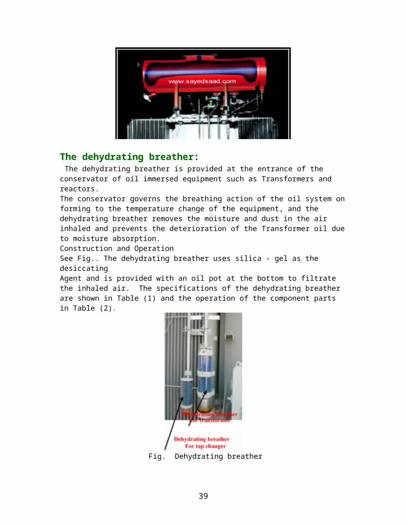
The dehydrating breather: The dehydrating breather is provided at the entrance of the conservator of oil immersed equipment such as Transformers and reactors. The conservator governs the breathing action of the oil system on forming to the temperature change of the equipment, and the dehydrating breather removes the moisture and dust in the air inhaled and prevents the deterioration of the Transformer oil due to moisture absorption.Construction and OperationSee Fig.. The dehydrating breather uses silica - gel as the desiccatingAgent and is provided with an oil pot at the bottom to filtrate the inhaled air. The specifications of the dehydrating breather are shown in Table (1) and the operation of the component parts in Table (2).
34
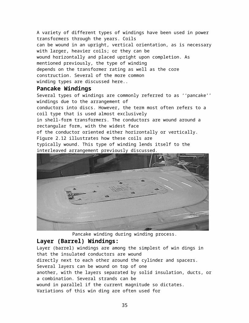
Fig. Dehydrating breather
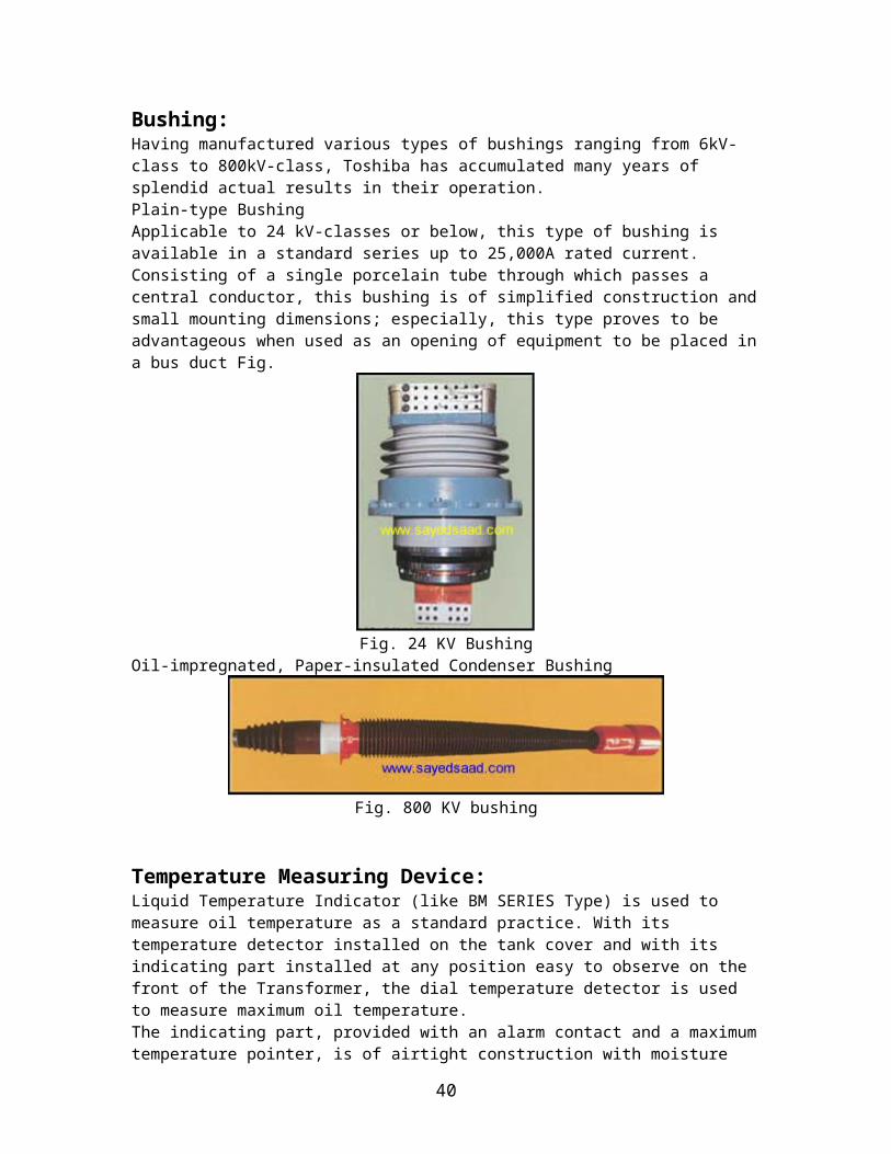
Bushing:Having manufactured various types of bushings ranging from 6kV-class to 800kV-class, Toshiba has accumulated many years of splendid actual results in their operation. Plain-type BushingApplicable to 24 kV-classes or below, this type of bushing is available in a standard series up to 25,000A rated current. Consisting of a single porcelain tube through which passes a central conductor, this bushing is of simplified construction and small mounting dimensions; especially, this type proves to be advantageous when used as an opening of equipment to be placed in a bus duct Fig.
Fig. 24 KV BushingOil-impregnated, Paper-insulated Condenser Bushing
35
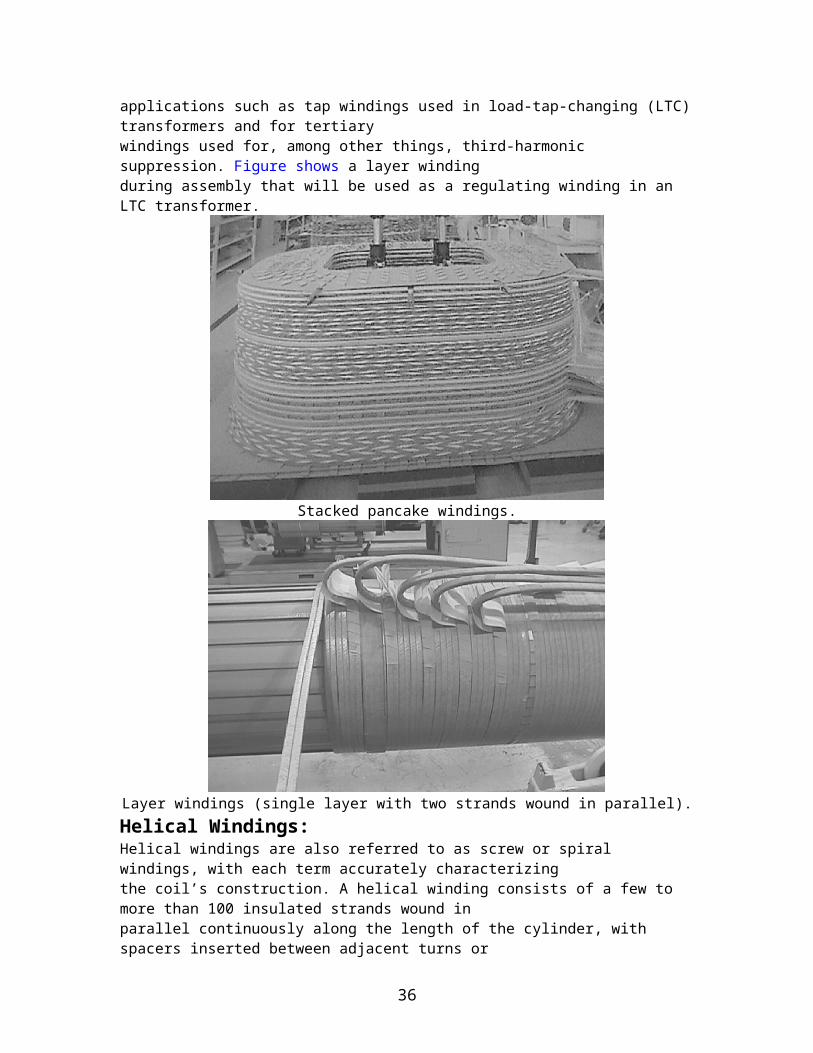
Fig. 800 KV bushing
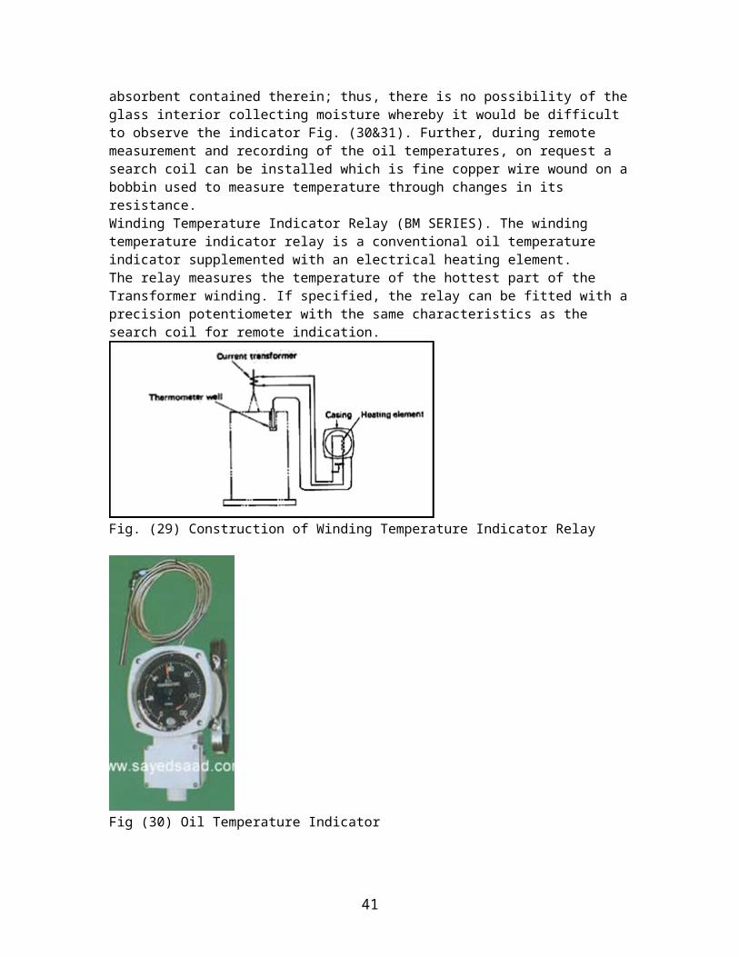
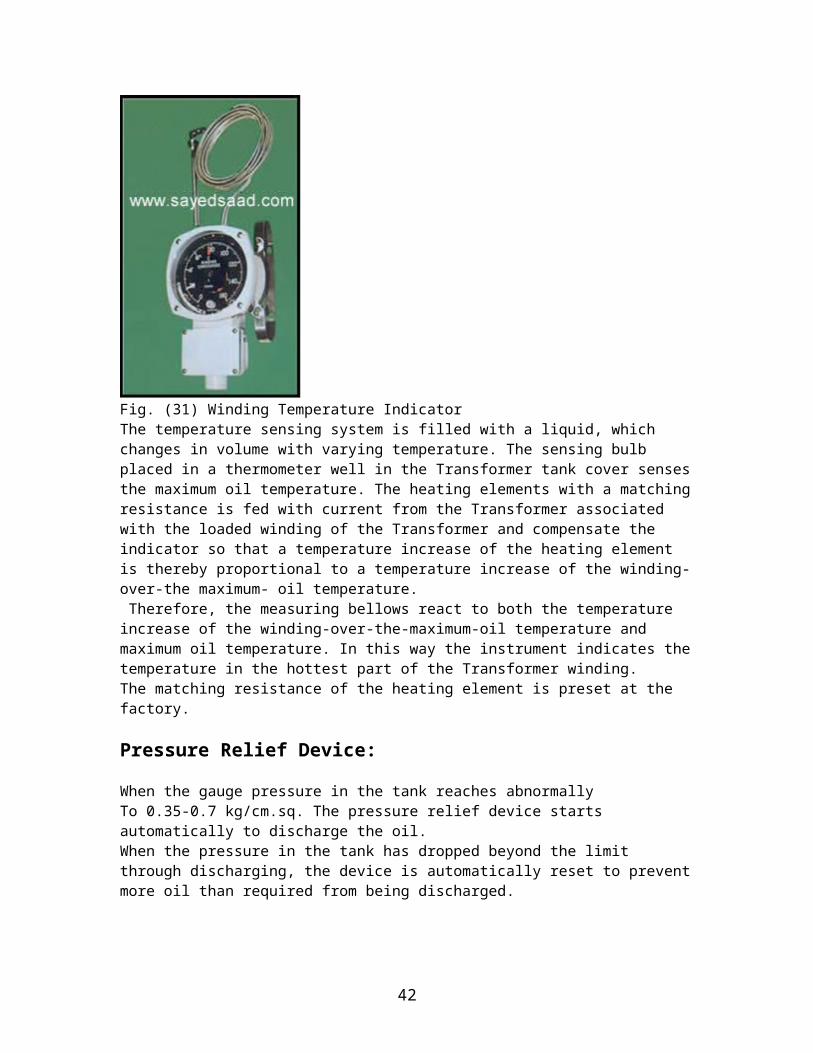
Temperature Measuring Device:Liquid Temperature Indicator (like BM SERIES Type) is used to measure oil temperature as a standard practice. With its temperature detector installed on the tank cover and with its indicating part installed at any position easy to observe on the front of the Transformer, the dial temperature detector is used to measure maximum oil temperature.The indicating part, provided with an alarm contact and a maximum temperature pointer, is of airtight construction with moisture absorbent contained therein; thus, there is no possibility of the glass interior collecting moisture whereby it would be difficult to observe the indicator Fig. (30&31). Further, during remote measurement and recording of the oil temperatures, on request a search coil can be installed which is fine copper wire wound on a bobbin used to measure temperature through changes in its resistance.Winding Temperature Indicator Relay (BM SERIES). The winding temperature indicator relay is a conventional oil temperature indicator supplemented with an electrical heating element.The relay measures the temperature of the hottest part of the Transformer winding. If specified, the relay can be fitted with a precision potentiometer with the same characteristics as the search coil for remote indication.
Fig. (29) Construction of Winding Temperature Indicator Relay
36
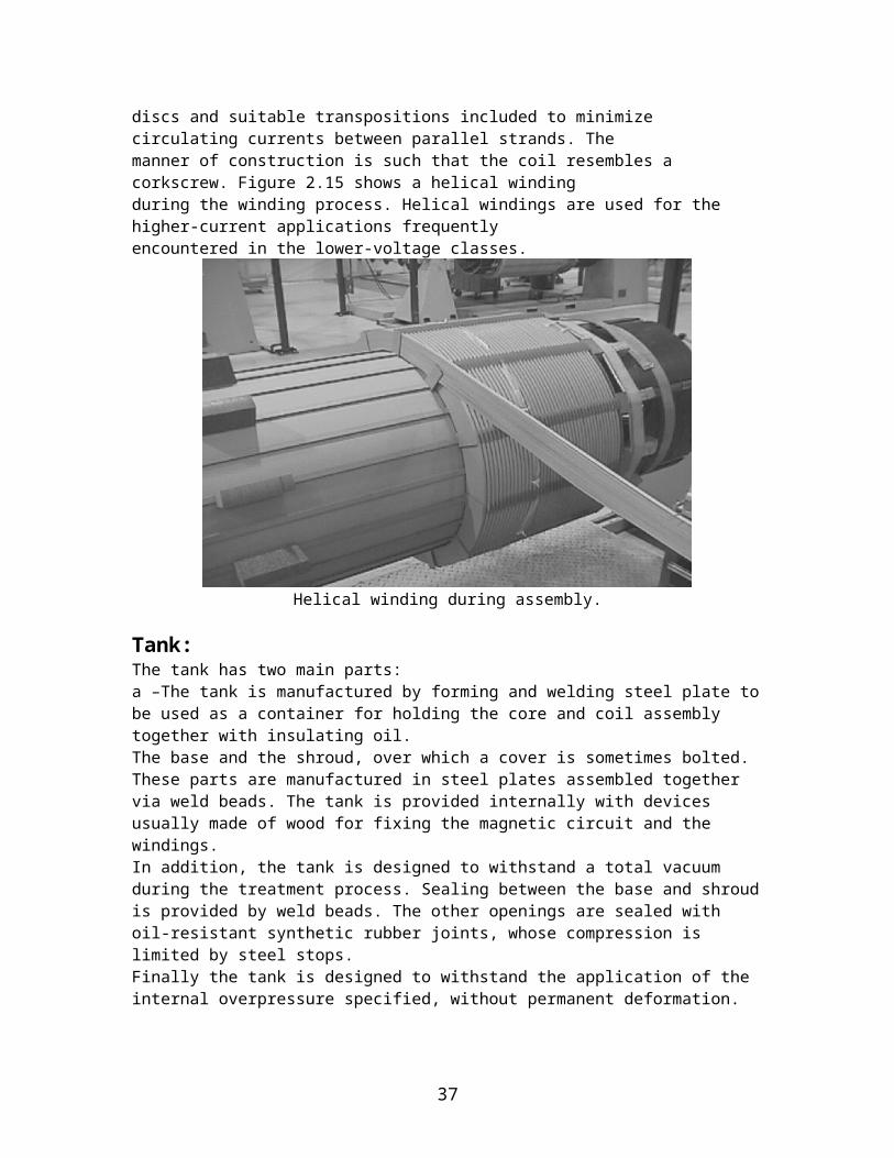
Fig (30) Oil Temperature Indicator
Fig. (31) Winding Temperature IndicatorThe temperature sensing system is filled with a liquid, which changes in volume with varying temperature. The sensing bulb placed in a thermometer well in the Transformer tank cover senses the maximum oil temperature. The heating elements with a matching resistance is fed with current from the Transformer associated with the loaded winding of the Transformer and compensate the indicator so that a temperature increase of the heating element is thereby proportional to a temperature increase of the winding-over-the maximum- oil temperature. Therefore, the measuring bellows react to both the temperature increase of the winding-over-the-maximum-oil temperature and maximum oil temperature. In this way the instrument indicates the temperature in the hottest part of the Transformer winding.The matching resistance of the heating element is preset at the factory.
37

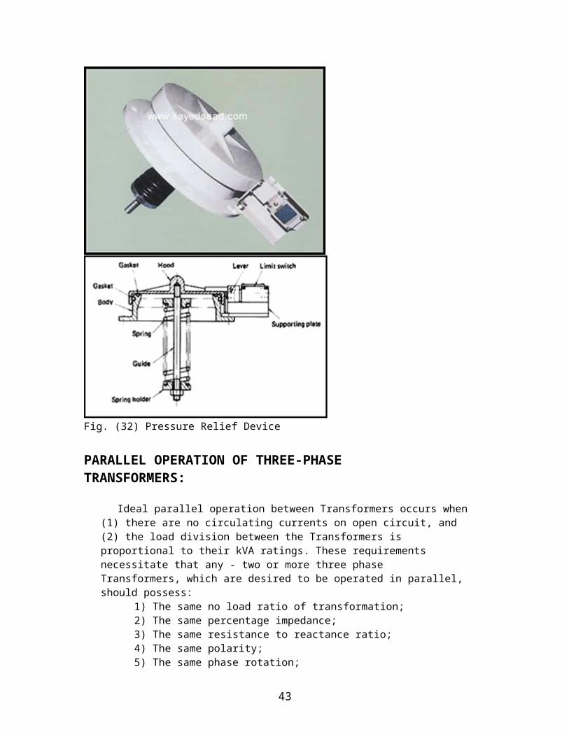
Pressure Relief Device:
When the gauge pressure in the tank reaches abnormally To 0.35-0.7 kg/cm.sq. The pressure relief device starts automatically to discharge the oil.When the pressure in the tank has dropped beyond the limit through discharging, the device is automatically reset to prevent more oil than required from being discharged.
Fig. (32) Pressure Relief Device
PARALLEL OPERATION OF THREE-PHASE TRANSFORMERS:
Ideal parallel operation between Transformers occurs when (1) there are no circulating currents on open circuit, and (2) the load division between the Transformers is proportional to their kVA ratings. These requirements necessitate that any - two or more three phase Transformers, which are desired to be operated in parallel, should possess:
1) The same no load ratio of transformation;2) The same percentage impedance;
38
3) The same resistance to reactance ratio;4) The same polarity;5) The same phase rotation; 6) The same inherent phase-angle displacement between primary
and secondary terminals. The above conditions are characteristic of all three phase Transformers whether two winding or three winding. With three winding Transformers, however, the following additional requirement must also be satisfied before the Transformers can be designed suitable for parallel operation.
7) The same power ratio between the corresponding windings.
The first four conditions need no explanation being the same as in single phase Transformers.
The fifth condition of phase rotation is also a simple requirement. It assumes that the standard direction of phase rotation is anti-clockwise. In case of any difference in the phase rotation it can be set right by simply interchanging two leads either on primary or secondary. It is the intention here to discuss the last two i.e., sixth and seventh conditions in detail.
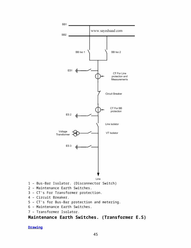
Bus-Bar Schemes used in a sub station :-Bus-Bar Isolator:
39
1 – Bus-Bar Isolator. (Disconnector Switch)2 – Maintenance Earth Switches. 3 – CT's For Transformer protection. 4 – Circuit Breaker. 5 – CT's for Bus-Bar protection and metering. 6 – Maintenance Earth Switches. 7 – Transformer Isolator. Maintenance Earth Switches. (Transformer E.S) Drawing
40
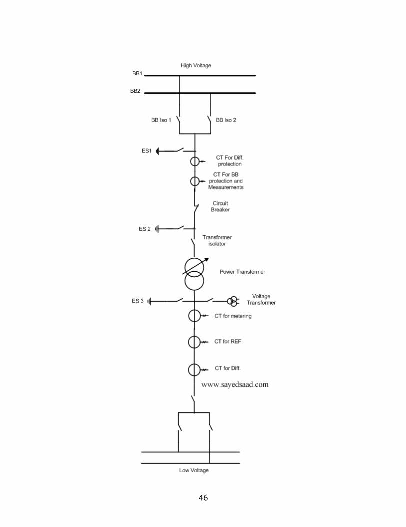
1 – Bus-Bar Isolator. (Disconnector Switch) 2 – Maintenance Earth Switches.
41
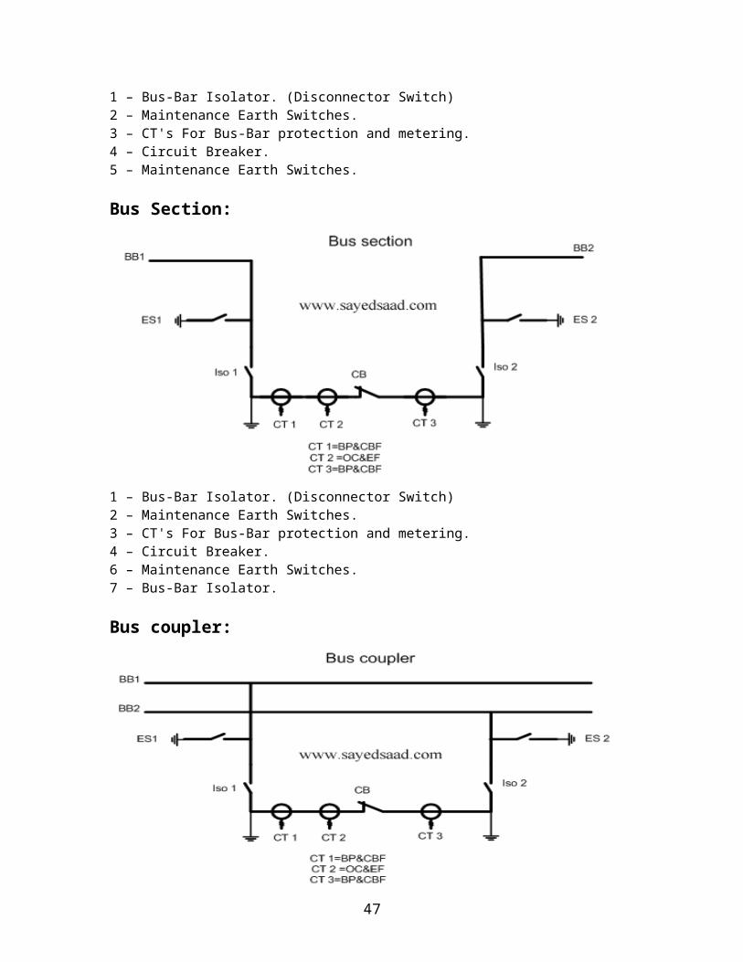
3 – CT's For Bus-Bar protection and metering. 4 – Circuit Breaker. 5 – Maintenance Earth Switches. Bus Section:
1 – Bus-Bar Isolator. (Disconnector Switch) 2 – Maintenance Earth Switches. 3 – CT's For Bus-Bar protection and metering. 4 – Circuit Breaker. 6 – Maintenance Earth Switches. 7 – Bus-Bar Isolator. Bus coupler:
Battery:
42
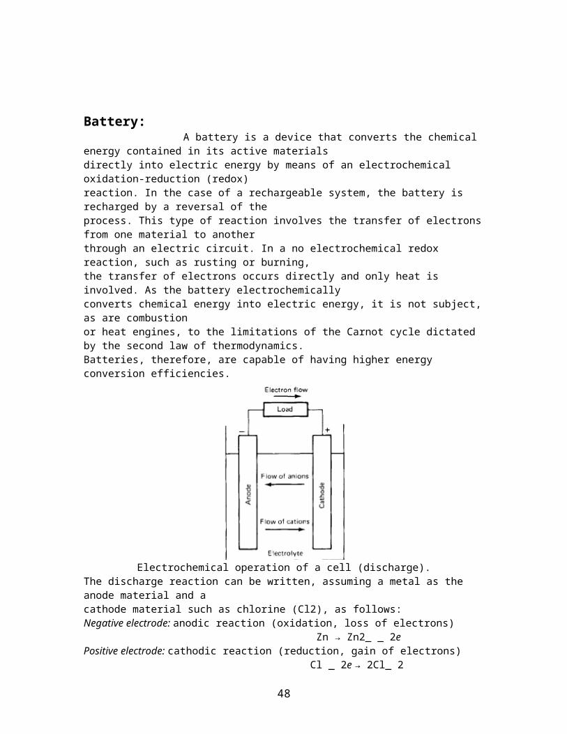
A battery is a device that converts the chemical energy contained in its active materialsdirectly into electric energy by means of an electrochemical oxidation-reduction (redox)reaction. In the case of a rechargeable system, the battery is recharged by a reversal of theprocess. This type of reaction involves the transfer of electrons from one material to anotherthrough an electric circuit. In a no electrochemical redox reaction, such as rusting or burning,the transfer of electrons occurs directly and only heat is involved. As the battery electrochemicallyconverts chemical energy into electric energy, it is not subject, as are combustionor heat engines, to the limitations of the Carnot cycle dictated by the second law of thermodynamics.Batteries, therefore, are capable of having higher energy conversion efficiencies.
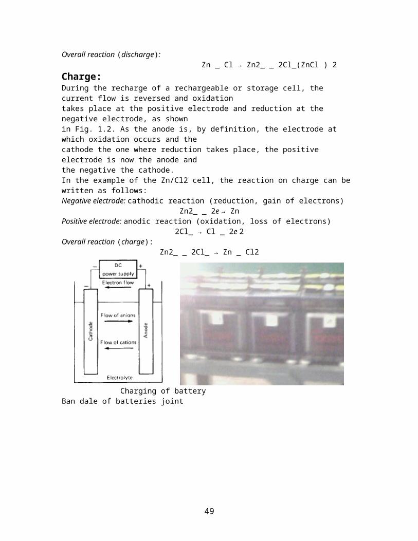
Electrochemical operation of a cell (discharge).The discharge reaction can be written, assuming a metal as the anode material and acathode material such as chlorine (Cl2), as follows:Negative electrode: anodic reaction (oxidation, loss of electrons) Zn → Zn2_ _ 2ePositive electrode: cathodic reaction (reduction, gain of electrons) Cl _ 2e → 2Cl_ 2Overall reaction (discharge): Zn _ Cl → Zn2_ _ 2Cl_(ZnCl ) 2Charge:During the recharge of a rechargeable or storage cell, the current flow is reversed and oxidationtakes place at the positive electrode and reduction at the negative electrode, as shownin Fig. 1.2. As the anode is, by definition, the electrode at which oxidation occurs and the
43

cathode the one where reduction takes place, the positive electrode is now the anode andthe negative the cathode.In the example of the Zn/Cl2 cell, the reaction on charge can be written as follows:Negative electrode: cathodic reaction (reduction, gain of electrons)
Zn2_ _ 2e → ZnPositive electrode: anodic reaction (oxidation, loss of electrons)
2Cl_ → Cl _ 2e 2Overall reaction (charge):
Zn2_ _ 2Cl_ → Zn _ Cl2
Charging of battery Ban dale of batteries joint
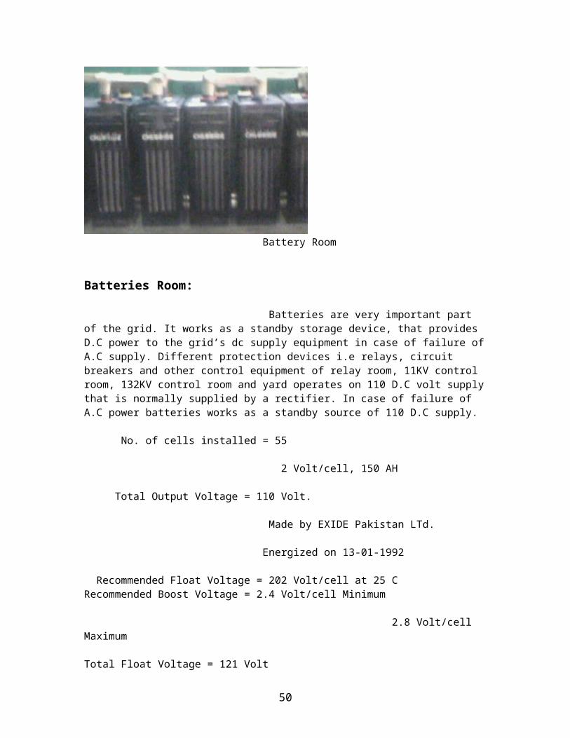
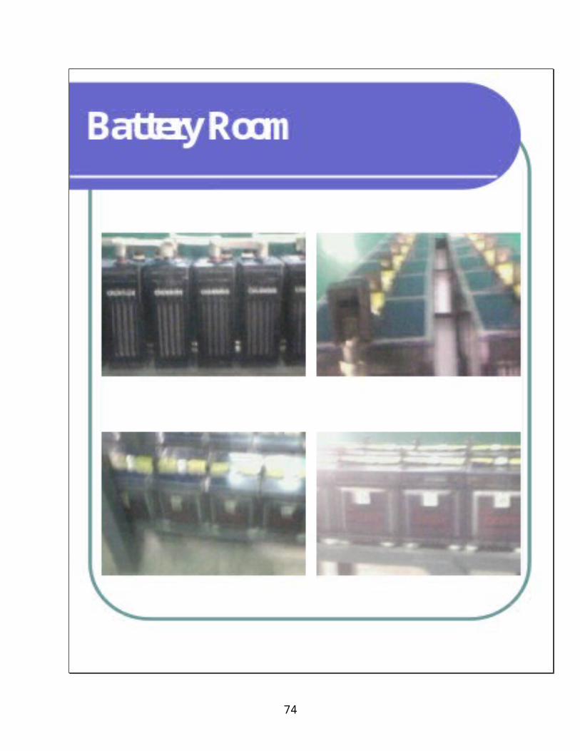
Battery Room
Batteries Room: Batteries are very important part of the grid. It works as a standby storage device, that provides D.C power to the grid’s dc supply equipment in case of failure of A.C supply. Different protection devices i.e relays, circuit breakers and other control equipment of relay room, 11KV control room, 132KV control room and yard operates on 110 D.C volt supply
44
that is normally supplied by a rectifier. In case of failure of A.C power batteries works as a standby source of 110 D.C supply.
No. of cells installed = 55 2 Volt/cell, 150 AH Total Output Voltage = 110 Volt. Made by EXIDE Pakistan LTd. Energized on 13-01-1992
Recommended Float Voltage = 202 Volt/cell at 25 CRecommended Boost Voltage = 2.4 Volt/cell Minimum 2.8 Volt/cell Maximum
Total Float Voltage = 121 Volt
Skills Learnt:- To understand the purpose of Grid Station, Breakers, Relays, Switching, Transformer, CT, PT,
Batteries as well as many more things which used at the 132KV Grid Station Bosan Road Multan.
45
Training Supervisor Trainee Student
Sig. Sig. Muhammad Tariq Khurshid Sb. Muhammad Shoaib Saleem Incharge B-Tech (Pass) Electrical 132kv Grid Station MEPCO University Roll# 31 Bosan Road Multan.
46
47
48
49
50
51

52
53
54
55
56
57
58
59
60
61

62
63
64
65
66
67
68

69
70
71
72
73
74
75
76
77
78