Embed Size (px)
Citation preview

Copyright © 2004-2005 ComAp s.r.o. Written by Ladislav Kadanik Prague, Czech Republic
ComAp, spol. s r.o. Světova 7, 180 00 Praha 8, Czech Republic Tel: +420 2 66316661, Fax: +420 2 66316647 E-mail: [email protected], www.comap.cz
InteliDrive
ID–DCU Marine Expandable engine controller
with electronic engines support
Constant speed applications AUX, EME, CMB Variable speed applications PRP
SW version 1.2, March 2005
User guide
ID-DCU-Marine-1.2, ©ComAp – March 2005 2 ID-DCU-Marine-1.2.pdf
Table of Contents Table of Contents ...............................................................................................................................................2
Abbreviations..................................................................................................................................................4 General description ............................................................................................................................................6 Terminal and dimensions ...................................................................................................................................7
Physical component and interface Descriptions ............................................................................................7 ID-DCU...........................................................................................................................................................7 ID-DCU Marine terminals ...............................................................................................................................8 ID-RPU terminals ...........................................................................................................................................9 ID-COM terminals ..........................................................................................................................................9 I-RD-CAN Marine (Remote Panel)...............................................................................................................10 ID DCU-Marine dimensions .........................................................................................................................13 I-RB16 technical description ........................................................................................................................14 IS-BIN16/8....................................................................................................................................................16 IS-AIN8.........................................................................................................................................................17 IGL-RA15 Remote annunciator....................................................................................................................17 IGS-PTM ......................................................................................................................................................18 IG-MU...........................................................................................................................................................19 IG-IB Internet bridge.....................................................................................................................................20 I-CB communication bridge.........................................................................................................................20
Recommended wiring.......................................................................................................................................21 ID-RPU wiring...............................................................................................................................................21 Complete system example...........................................................................................................................22 Complete system without RPU ....................................................................................................................22 Electronic engine without redundancy line...................................................................................................23 Engine without ECU (mechanical engine) ...................................................................................................23 Scania S6 wiring example............................................................................................................................24 Bus/Communication architecture .................................................................................................................24
Getting started ..................................................................................................................................................26 How to install ................................................................................................................................................26 ID-DCU Analog inputs hardware configuration ............................................................................................28 ID-DCU Analog inputs software configuration .............................................................................................28 Hardware connection ...................................................................................................................................33 Analog inputs on iS-AIN8 .............................................................................................................................33 Binary inputs iS-BIN16/8 ..............................................................................................................................36 Binary outputs on iS-BIN16/8.......................................................................................................................37
Binary Inputs.....................................................................................................................................................40 Binary inputs from J1939 configuration........................................................................................................43 Binary inputs protection................................................................................................................................44
Binary outputs...................................................................................................................................................46 Source: Log Bout .........................................................................................................................................46 Source: RPU unit .........................................................................................................................................49 Source – Prg.states.....................................................................................................................................50 Source: Ana protections...............................................................................................................................52 Source: Bin protections ................................................................................................................................52 Source – Binary CU .....................................................................................................................................53 Source – RPU unit .......................................................................................................................................53 Source – Binary Inputs.................................................................................................................................53 Source – J1939 ............................................................................................................................................53 Binary output to J1939 configuration: Source-Value ..................................................................................54
Logical analog inputs list ..................................................................................................................................55 Obligatory J1939 items ................................................................................................................................55 Analog inputs from J1939 configuration.......................................................................................................56 Analog inputs protection...............................................................................................................................56
Analog outputs..................................................................................................................................................65 InteliDrive – Engine ECU communication ........................................................................................................66 Setpoints...........................................................................................................................................................67

ID-DCU-Marine-1.2, ©ComAp – March 2005 3 ID-DCU-Marine-1.2.pdf
Password......................................................................................................................................................67 Basic settings ...............................................................................................................................................68 Engine params .............................................................................................................................................70 Engine protect ..............................................................................................................................................74 RPMdep protect PRP only ..........................................................................................................................77 Load sharing PRP only ..............................................................................................................................78 Active call/SMS ............................................................................................................................................81 Date and time...............................................................................................................................................82 Protections ...................................................................................................................................................82
Operator Interface ............................................................................................................................................83 Pushbuttons and LEDs ................................................................................................................................83 How to select engine mode ?.......................................................................................................................83 Display menus..............................................................................................................................................84 How to view measured data?.......................................................................................................................84 How to view and edit set points? .................................................................................................................84 How to view the HISTORY menu?...............................................................................................................84 How to check the serial number and software revision? .............................................................................84 How to find active alarms ? ..........................................................................................................................85 Controller screens ........................................................................................................................................85 Functions available from ID-DCU front panel keys ......................................................................................89
ID-DCU functions..............................................................................................................................................90 Default archives ...........................................................................................................................................90 Operational modes.......................................................................................................................................90 Function description details..........................................................................................................................92 Universal states............................................................................................................................................95
ID-RPU .............................................................................................................................................................97 ID-RPU functions .........................................................................................................................................98 ID-RPU over speed setting ..........................................................................................................................99
Controller configuration and monitoring .........................................................................................................101 Direct connection to the PC .......................................................................................................................101 DriveConfig.................................................................................................................................................101 Configuration steps ....................................................................................................................................102 DriveMonitor ...............................................................................................................................................102 Password protection...................................................................................................................................103 Modbus protocol.........................................................................................................................................104
Technical data ................................................................................................................................................105 ID-DCU.......................................................................................................................................................105 CAN bus interface ......................................................................................................................................106 ID-RPU.......................................................................................................................................................107

ID-DCU-Marine-1.2, ©ComAp – March 2005 4 ID-DCU-Marine-1.2.pdf
Abbreviations aid Archive file extension for InteliDrive controller AIN Controller or extension module Analog input Alarm General term for any active engine protection Warning, Shutdown, … etc. Alarm list
Controller or PC DriveMonitor screen with list of active and unaccepted alarms detected from ID controller.
ECU Alarm list
Controller or PC DriveMonitor screen with list of active and unaccepted alarms detected from engine ECU.
AOUT Controller Analog OUTput or outputs group. Archive
Usually aid file that contains all controller data: configuration, setpoints setting and history records.
AUX Controller application (archive, operational mode) for Auxiliary engines. BI Controller binary input. BIN Controller binary inputs group. BO Controller binary output. BOUT Controller binary outputs group. CAN Control Area Network – serial data link. Cd Cool down protection, cooling period is included before engine stops. CMB Controller Combined mode. D+
Controller function for battery charging function check and/or engine running indication.
DC DriveConfig, PC software for InteliDrive configuration. DM DriveConfig, PC software for InteliDrive monitoring. DriveConfig PC software for InteliDrive configuration. DriveMonitor PC software for InteliDrive monitoring. ECU Engine Electronic (injection) Control Unit. ECU alarm Alarm detected in engine electronic control unit that is received via J1939. EME InteliDrive Emergency operational mode. EMS I. Electronic Management System – version I. EMS II. Electronic Management System – version II. Fls Controller sensor fail alarm. FMI Failure Mode Identifier. GSM modem Modem for Global System of Mobile communicationHistory
List of alarms and operational states with Reason, Date and Time and adjustable values set that is stored in controller, can be listed from the screen or DriveMonitor.
HRB Controller Harbor mode. I-CB
Inteli - Communication bridge = controller interface for other electronic engines like MTU, CAT etc.. that are not supported yet.
ID InteliDrive controller. ID-COM
InteliDrive communication module with interface to J1939, J1587 and to other controllers.
ID-DCU InteliDrive – DieselControlUnit. ID-MCU InteliDrive – Marine Controller Unit with Volvo Penta front panel modification. ID-RPU
InteliDrive – Redundancy Protection Unit = ID backup unit for Over speed and Emergency stop protection.
IG-IB InteliGen – Internet Bridge = controller interface for internet communication. IGL-RA15 Remote Anunciator = external 15 LED indication panel (three colors, configurable). IG-MU
InteliGen – Modem Unit = controller interface for multiple engines application – one point communication with group or one point modem connection.
IGS-PTM Controller extension module with 8 binary inputs and outputs and 4 analog inputs. I-RB Inteli Relay board = interface board with 16 free contact relays. I-RB16 Inteli Relay board = interface board with 16 free contact relays.

ID-DCU-Marine-1.2, ©ComAp – March 2005 5 ID-DCU-Marine-1.2.pdf
I-RD
Inteli Remote Display (Remote Panel) = the same panel like on controller, all data received via CAN2 bus.
I-RD-CAN
Inteli Remote Display (Remote Panel) = the same panel like on controller, all data received via CAN2 bus.
I-RP
Inteli Remote Display (Remote Panel) = the same panel like on controller, all data received via CAN2 bus.
IS-AIN8 InteliSys – Analog input module = extension module with 8 analog inputs. IS-BIN16/8
InteliSys – Binary input/output module = extension module with 16 binary inputs and 8 binary outputs.
J1587
The J1587 bus is mainly used for redundant signals; system diagnosis and software download on after market tools.
J1587/J1708 See J1587 J1939 The J1939 bus in mainly used for engine controls and engine monitoring. KWP2000 Scania Communication protocol. mhx Extension for controller firmware (Motorola HeX file). MID Message Identification Assignments. OFF
Controller mode when power supply is switched on, but all binary outputs and start commands are disabled = engine start is blocked.
PID Parameter Identification Assignments. PPID Proprietary Parameter Identification Assignments. RPM Engine Revolution Per Minute – engine speed. PCB Printed Circuit Board PSID Proprietary Parameter Identification Assignments. RS232
Standard serial data line for PC or Modem connection (controller programming or monitoring).
Sd Shut down protection. SID Subsystem Identification Assignments. Wrn Warning protection.
ID-DCU-Marine-1.2, ©ComAp – March 2005 6 ID-DCU-Marine-1.2.pdf
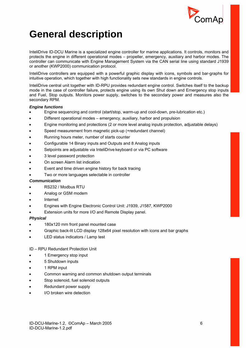
General description InteliDrive ID-DCU Marine is a specialized engine controller for marine applications. It controls, monitors and protects the engine in different operational modes – propeller, emergency, auxiliary and harbor modes. The controller can communicate with Engine Management System via the CAN serial line using standard J1939 or another (KWP2000) communication protocol.
InteliDrive controllers are equipped with a powerful graphic display with icons, symbols and bar-graphs for intuitive operation, which together with high functionality sets new standards in engine controls.
InteliDrive central unit together with ID-RPU provides redundant engine control. Switches itself to the backup mode in the case of controller failure, protects engine using its own Shut down and Emergency stop inputs and Fuel, Stop outputs. Monitors power supply, switches to the secondary power and measures also the secondary RPM.
Engine functions • Engine sequencing and control (start/stop, warm-up and cool-down, pre-lubrication etc.) • Different operational modes – emergency, auxiliary, harbor and propulsion • Engine monitoring and protections (2 or more level analog inputs protection, adjustable delays) • Speed measurement from magnetic pick-up (+redundant channel) • Running hours meter, number of starts counter • Configurable 14 Binary inputs and Outputs and 8 Analog inputs • Setpoints are adjustable via InteliDrive keyboard or via PC software • 3 level password protection • On screen Alarm list indication • Event and time driven engine history for back tracing • Two or more languages selectable in controller Communication • RS232 / Modbus RTU • Analog or GSM modem • Internet • Engines with Engine Electronic Control Unit: J1939, J1587, KWP2000 • Extension units for more I/O and Remote Display panel. Physical • 180x120 mm front panel mounted case • Graphic back-lit LCD display 128x64 pixel resolution with icons and bar graphs • LED status indicators / Lamp test ID – RPU Redundant Protection Unit • 1 Emergency stop input • 5 Shutdown inputs • 1 RPM input • Common warning and common shutdown output terminals • Stop solenoid, fuel solenoid outputs • Redundant power supply • I/O broken wire detection

ID-DCU-Marine-1.2, ©ComAp – March 2005 7 ID-DCU-Marine-1.2.pdf
Terminal and dimensions
Physical component and interface Descriptions Module ID-DCU Central unit InteliDrive central unit:
14 BIN, 14BOUT, 8 AIN, 1xRS232, 1xCAN1 (full), 1xCAN2 (TTL), 1x Sync.Data line (TTL)
ID-RPU Redundancy unit
InteliDrive Redundancy Protection Unit with 5 SD and one Emergency stop input one Wrn, Sd Fuel solenoid and one Stop solenoid output.
ID-COM Communication interface
InteliDrive Communication interface for inter-controller or Remote display CAN1 line and for Redundancy synchronous J1708/1587 data line.
I-RB Relay board 16 relays with free NO/NC contacts for binary outputs separation I-RD-CAN Remote display InteliDrive Remote display (Slave panel), CAN or RS232 interface I/O extension IS-AIN8 8 analog inputs Configurable for
VDO, PT100, PT1000, Thermocouples, mA, Volts IS-BIN16/8 Extension
module 16 Binary inputs, 8 Binary outputs
IGS-PTM Extension module
8 BIN, 8 BOUT, 4 AIN, 1 AOUT
IGL-RA15 External LED indication panel
Configurable 15 LED and Horn signal.
Communication IG-MU Multiple engines modem interface. IG-IB Internet interface Hint: IG-IOM extension unit is not compatible with ID-DCU.
ID-DCU There exist two front panel modifications: according panel below and without I/O button. There must be used corresponding aid archive – see table below.
ID-DCU-Marine-1.2, ©ComAp – March 2005 8 ID-DCU-Marine-1.2.pdf
Front panel LED Right RED Active alarm indication Blinks when new alarm is activated.
Steady lights after “Fault reset” confirmation - when alarm is still active. Disappears after “Fault reset” confirmation – when alarm is inactive.
Right GREEN Engine running indication Light when engine is running. Left GREEN Indication of Binary output
Close load state or Clutch connect in PRP
Light when output is Closed.
Archive files Two controller panel versions are available. Panel with I/O button Panel without I/O button DCU-Marine-AUX-1.2.aid DCU-Marine-EME-1.2.aid DCU-Marine-CMB-1.2.aid DCU-Marine-PRP-1.2.aid
VP-DCU-Marine-AUX-1.2.aid VP-DCU-Marine-EME-1.2.aid VP-DCU-Marine-CMB-1.2.aid VP-DCU-Marine-PRP-1.2.aid
Hint: Please check the last software version.
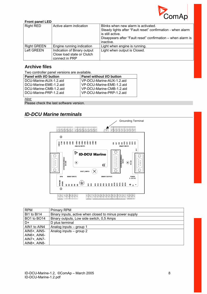
ID-DCU Marine terminals Grounding Terminal
BOOT JUMPER
BINARY INPUTSRPM
BINARY INPUTSANALOG INPUTS
BINARY OUTPUTS POWER8 - 36 V DC
EXTE
NSIO
NMO
DULE
ID-R
PU
RS23
2
LB1
EXTE
NSIO
NMO
DULE
ID-C
OM
+ -RPM
GND
RPM
IN
BI1
BI2
BI3
BI4
BI5
SHIE
LDCO
M
D+BO1
BO2
BO3
BO4
BO5
BO8
BO6
BO12
BO13
BO14
BO9
BO7
BO10
BO11
AIN1
AIN2
AIN3
AIN4
AIN6
+
AIN5
+
AIN8
+AI
N8-
AIN6
-
AIN5
-
AIN7
+AI
N7-
BI6
BI7
BI8
BI9
BI10
BI11
BI13
BI12
BI14
RPM Primary RPM BI1 to BI14 Binary inputs, active when closed to minus power supply BO1 to BO14 Binary outputs, Low side switch, 0,5 Amps D+ D plus terminal AIN1 to AIN4 Analog inputs – group 1 AIN5+, AIN5- AIN6+, AIN6- AIN7+, AIN7- AIN8+, AIN8-
Analog inputs – group 2

ID-DCU-Marine-1.2, ©ComAp – March 2005 9 ID-DCU-Marine-1.2.pdf
ID-DCU Marine -LT version with display preheating LT is an option for extending of operating temperature range from -20 to -40 °C. Heating foil is not part of standard ID-DCU and ID-MCU (without -LT extension).
Board temperature
+5 °C- 40 °C
Preh
eatin
g
3,5 W
The only one low temperature sensitive part is the controller display. ID-DCU-Marine-LT version contains a preheating foil on the display activated below +5°C (measured on the PCB). Heating is switched off when controller power supply is below 10VDC (together with display backlight).
ID-RPU terminals Redundant Protection Unit. ID-RPU is mounted directly to ID-DCU box.
RPM Secondary RPM +SOL Common power supply for galvanic separated Fuel solenoid and Stop solenoid
outputs. FUEL SOL Fuel solenoid output, High side switch (8 Amps), BW detection in open state or above
1 amp load STOP SOL Stop solenoid output, High side switch (8 Amps), BW detection in open state or above
1 amp load GND SOL Common GND for Fuel and Stop solenoid outputs COMM.SD Common Shut down output, Low side switch (0,5 Amps) COMM.WRN Common Warning output, Low side switch (0,5 Amps) SD1 to SD5 Shut down inputs, BW detection, Normally open EM.STOP Emergency stop input, Normally closed A+, A- Primary battery B+, B- Secondary battery COM+, COM- Battery A, B output to ID-DCU Hint: 10 kilo ohm resistor must be connected in parallel to SD1 to SD5 inputs.
ID-COM terminals Communication interface. ID-COM is mounted directly to ID-DCU box.
ID-DCU-Marine-1.2, ©ComAp – March 2005 10 ID-DCU-Marine-1.2.pdf
CAN1 Extension modules: EMS, IS-AIN8, IS-BIN16/8, IGS-PTM, IGL-RA15 CAN2 Intercontroller: I-RD-CAN, IG-MU, IG-IB, others ID-DCU
ID-DCU ID-COM
INTERFACE
INTERFACE
INTERFACE
CAN1J1939
J1587
CAN2PRO
CES
SOR
TTL
TTL
TTL
120 ohms
120 ohms
Hint: Put jumper to connect the internal 120 ohms terminating resistor for CAN2 interface. ID-COM module is not required when inter-controller CAN2 and J1587 lines are not used. In this case connect Extension modules CAN1 directly to Extension modules port ID-COM on ID-DCU (9-pin connector: 5=H, 9=L).
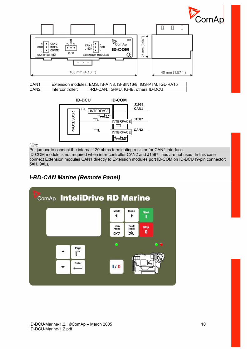
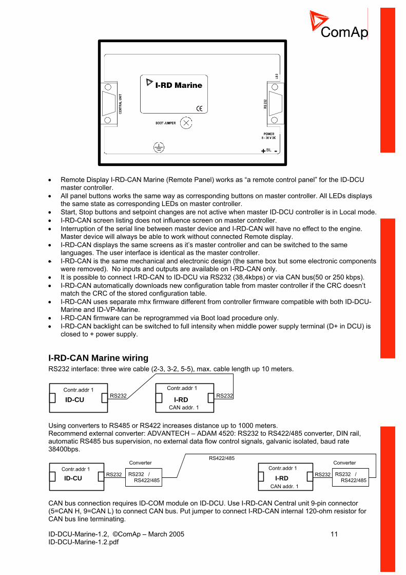
I-RD-CAN Marine (Remote Panel)
ID-DCU-Marine-1.2, ©ComAp – March 2005 11 ID-DCU-Marine-1.2.pdf
BL
• Remote Display I-RD-CAN Marine (Remote Panel) works as “a remote control panel” for the ID-DCU
master controller. • All panel buttons works the same way as corresponding buttons on master controller. All LEDs displays
the same state as corresponding LEDs on master controller. • Start, Stop buttons and setpoint changes are not active when master ID-DCU controller is in Local mode. • I-RD-CAN screen listing does not influence screen on master controller. • Interruption of the serial line between master device and I-RD-CAN will have no effect to the engine.
Master device will always be able to work without connected Remote display. • I-RD-CAN displays the same screens as it’s master controller and can be switched to the same
languages. The user interface is identical as the master controller. • I-RD-CAN is the same mechanical and electronic design (the same box but some electronic components
were removed). No inputs and outputs are available on I-RD-CAN only. • It is possible to connect I-RD-CAN to ID-DCU via RS232 (38,4kbps) or via CAN bus(50 or 250 kbps). • I-RD-CAN automatically downloads new configuration table from master controller if the CRC doesn’t
match the CRC of the stored configuration table. • I-RD-CAN uses separate mhx firmware different from controller firmware compatible with both ID-DCU-
Marine and ID-VP-Marine. • I-RD-CAN firmware can be reprogrammed via Boot load procedure only. • I-RD-CAN backlight can be switched to full intensity when middle power supply terminal (D+ in DCU) is
closed to + power supply.
I-RD-CAN Marine wiring RS232 interface: three wire cable (2-3, 3-2, 5-5), max. cable length up 10 meters.
ID-CU I-RDRS232 RS232Contr.addr 1
CAN addr. 1
Contr.addr 1
Using converters to RS485 or RS422 increases distance up to 1000 meters. Recommend external converter: ADVANTECH – ADAM 4520: RS232 to RS422/485 converter, DIN rail, automatic RS485 bus supervision, no external data flow control signals, galvanic isolated, baud rate 38400bps.
ID-CU I-RDRS232 RS232RS232 / RS422/485
RS232 / RS422/485
RS422/485Converter Converter
Contr.addr 1
CAN addr. 1
Contr.addr 1
CAN bus connection requires ID-COM module on ID-DCU. Use I-RD-CAN Central unit 9-pin connector (5=CAN H, 9=CAN L) to connect CAN bus. Put jumper to connect I-RD-CAN internal 120-ohm resistor for CAN bus line terminating.
ID-DCU-Marine-1.2, ©ComAp – March 2005 12 ID-DCU-Marine-1.2.pdf
ID-CU CAN2ID
-CO
MI-RD
Contr.addr 1
CAN addr. 1
Contr.addr 15 - CAN H9 = CAN L
120
ohm
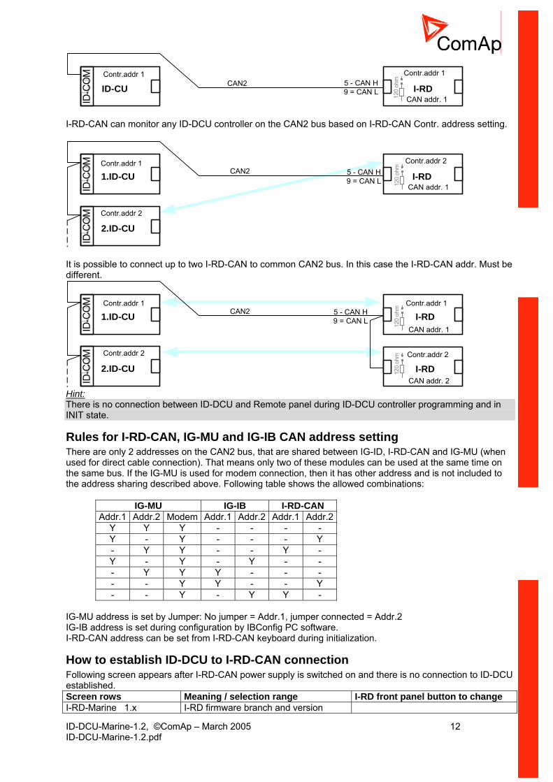
I-RD-CAN can monitor any ID-DCU controller on the CAN2 bus based on I-RD-CAN Contr. address setting.
1.ID-CU CAN2
ID-C
OM
I-RD
2.ID-CU
ID-C
OM
`
`
Contr.addr 1
Contr.addr 2
CAN addr. 1
Contr.addr 25 - CAN H9 = CAN L 12
0 oh
m
It is possible to connect up to two I-RD-CAN to common CAN2 bus. In this case the I-RD-CAN addr. Must be different.
1.ID-CU CAN2
ID-C
OM
I-RD
2.ID-CU
ID-C
OM
I-RD
CAN addr. 1
CAN addr. 2
Contr.addr 1
Contr.addr 2
Contr.addr 1
Contr.addr 2
5 - CAN H9 = CAN L
120
ohm
120
ohm
Hint: There is no connection between ID-DCU and Remote panel during ID-DCU controller programming and in INIT state.
Rules for I-RD-CAN, IG-MU and IG-IB CAN address setting There are only 2 addresses on the CAN2 bus, that are shared between IG-ID, I-RD-CAN and IG-MU (when used for direct cable connection). That means only two of these modules can be used at the same time on the same bus. If the IG-MU is used for modem connection, then it has other address and is not included to the address sharing described above. Following table shows the allowed combinations:
IG-MU IG-IB I-RD-CAN Addr.1 Addr.2 Modem Addr.1 Addr.2 Addr.1 Addr.2
Y Y Y - - - - Y - Y - - - Y - Y Y - - Y - Y - Y - Y - - - Y Y Y - - - - - Y Y - - Y - - Y - Y Y -
IG-MU address is set by Jumper: No jumper = Addr.1, jumper connected = Addr.2 IG-IB address is set during configuration by IBConfig PC software. I-RD-CAN address can be set from I-RD-CAN keyboard during initialization.
How to establish ID-DCU to I-RD-CAN connection Following screen appears after I-RD-CAN power supply is switched on and there is no connection to ID-DCU established. Screen rows Meaning / selection range I-RD front panel button to change I-RD-Marine 1.x I-RD firmware branch and version
ID-DCU-Marine-1.2, ©ComAp – March 2005 13 ID-DCU-Marine-1.2.pdf
ComAp 2004 Copyright SN: xxxxxxxx Controller serial number Contr. Addr: 1 Controller address: 1 to 32 and AUTO Up, Down Connection: CAN addr.1 Connection: CAN addr.1, CAN addr.2,
RS232 Page
NO CONNECTION TRYING…. , PROGRAMMING I-RD status during Init state.
1. Connect selected communication line between ID-DCU controller and I-RD-CAN panel. 2. Switch ID-DCU and I-RD-CAN power supply on. 3. After I-RD-CAN Initialization screen appears: Use front panel Up/Down buttons to change Controller
address in the range 1 to 32 or AUTO. I-RD-CAN automatically increases the controller address and try to open connection. This I-RD-CAN Controller address must correspond to connected ID-DCU Basic setting: Controller address setpoint.
4. Use Page button to set I-RD-CAN connection: CAN addr.1, CAN addr.2 or RS232. 5. Then press Enter button to start data download. Message TRAYING … appears on the I-RD-CAN
screen. Unsuccessful attempt to read data is repeated each 15 sec. 6. The Programming bargraph appears on I-RD-CAN screen after connection is opened. 7. Standard ID-DCU screen appears after complete configuration is loaded to I-RD-CAN.
Hint: To switch to Init screen press Page button for more than 2 sec when CFG table error message appears on the I-RD-CAN screen.
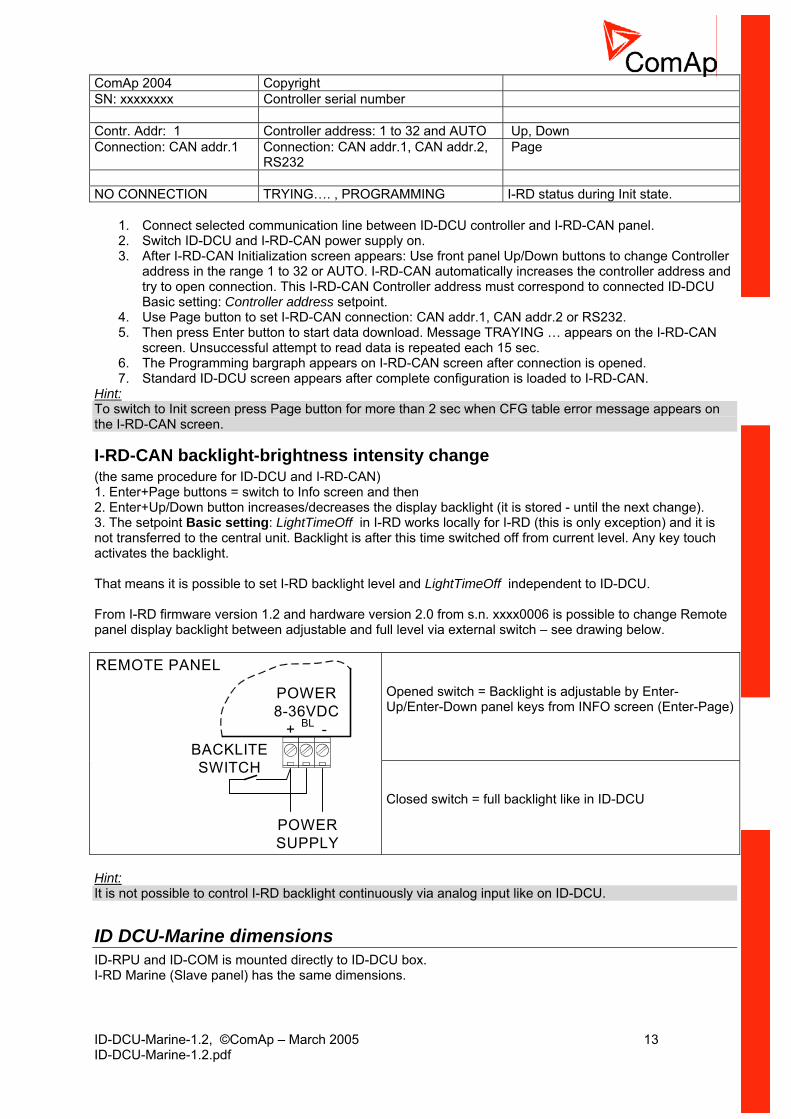
I-RD-CAN backlight-brightness intensity change (the same procedure for ID-DCU and I-RD-CAN) 1. Enter+Page buttons = switch to Info screen and then 2. Enter+Up/Down button increases/decreases the display backlight (it is stored - until the next change). 3. The setpoint Basic setting: LightTimeOff in I-RD works locally for I-RD (this is only exception) and it is not transferred to the central unit. Backlight is after this time switched off from current level. Any key touch activates the backlight. That means it is possible to set I-RD backlight level and LightTimeOff independent to ID-DCU. From I-RD firmware version 1.2 and hardware version 2.0 from s.n. xxxx0006 is possible to change Remote panel display backlight between adjustable and full level via external switch – see drawing below.
Opened switch = Backlight is adjustable by Enter-Up/Enter-Down panel keys from INFO screen (Enter-Page)
POWER8-36VDC
+ -
POWERSUPPLY
BACKLITESWITCH
REMOTE PANEL
Closed switch = full backlight like in ID-DCU
BL
Hint: It is not possible to control I-RD backlight continuously via analog input like on ID-DCU.
ID DCU-Marine dimensions ID-RPU and ID-COM is mounted directly to ID-DCU box. I-RD Marine (Slave panel) has the same dimensions.

ID-DCU-Marine-1.2, ©ComAp – March 2005 14 ID-DCU-Marine-1.2.pdf
ID-RPU
ID-CU
ID-COM
183 (7,2")
80(3
,1")
42,5
(1,7
")24 (0,9
")
47(1
,8")
~11
0(4
,3")
170 (8,87")
RS232
123
(4,8
")110
(4,4
")
Cutoutfor InteliDrive
113 x 175 mm(4.4 x 6,9“)
ID-DCU box is fixed using four screw clips.
I-RB16 technical description Relay board contains 16 relays for ID-DCU binary (open collector) output separation. All relays are placed in sockets. Number relays: 16 in socket Nominal voltage: 24 VDC Voltage range: 16,8 – 36 VDC Relay opens at: 10% of nominal voltage Electric / mechanic cycles: 100 000 / 10 000 000 Operating temperature range: - 40°C to 70°C Maximal load: 16A resistive load 4A inductive load Contacts protection: varistor 14DK390 Relay-connector connection:
1-2 n.o. 1-3 n.c. 1
K2 3
Mechanical dimension I-RB16 is 35 mm DIN rail mounted. One unit contains two parts (separate PCB) 8 relays each on common plastic base. I-RB16 is 60mm high from DIN rail base.

ID-DCU-Marine-1.2, ©ComAp – March 2005 15 ID-DCU-Marine-1.2.pdf
16X17
11 1 11 1 11
1 +X18
11 1 11 1 11
RE1
RE2
RE3
ER4
RE5
RE6
RE7
RE8
RE9
RE10
RE11
ER12
RE13
RE14
RE15
RE16
X3 X1X2X6 X4X5X8 X7X11 X9X10X14 X12X13X16 X15
9 + 8
16 X18 9 +View B
X18
8 X17 1 +
View B
3 X1 1
X1 X2 X3 X4 X5 X6 X7 X8 X9 X10 X11 X12 X13 X14 X15 X16
3 X2 1 3 X3 1 3 X4 1 3 X5 1 3 X6 1 3 X7 1 3 X8 1 3 X9 1 3 X10 1 3 X11 1 3 X12 1 3 X13 1 3 X14 1 3 X15 1 3 X16 1
View A300
95
X17
View A Hint: I-RB contains two separate boards, 8 relay each. It can be ordered as I-RB8 as well.
Harness (on request only) There is one tail for connection to ID-DCU (14 channels) and one part to ID-RPU (2 channels). I-RB16 +24VDC power supply wire must be connected to ID-DCU separately. Used cable: LAPP KABEL, ŐLFLEX, 18x0,5.
1
2
34
5
6
7
8
9
1
2
34
5
6
7
8
9
K17
K18
BO1
BO2
BO3
BO4
BO5
BO6
BO7
BO8
BO9
BO10
BO11
BO12
BO13
BO14
BO15
BO16
+24V
BO15
BO16
1,5 m
+24V
ID-CU
ID-RPU
BO1
BO2
BO3
BO4
BO5
BO6
BO7BO8
BO9
BO10BO11
BO12
BO13
BO14

ID-DCU-Marine-1.2, ©ComAp – March 2005 16 ID-DCU-Marine-1.2.pdf
IS-BIN16/8
45 (1,8")146 (5,7")
160
(6,3
") 40 (1,6")
25 (1,0")
IN1
-
RPM
+
IN 2
IN1
+
RPM
-
IS-BIN16/8 unit is DIN railmount (35mm)
ID-DCU-Marine-1.2, ©ComAp – March 2005 17 ID-DCU-Marine-1.2.pdf
IS-AIN8
46,4 (18,3")
40 (15,7")
25 (9,8")
70 (27,5")
146 (57,5")
160
(63"
)
POWER8 - 36V DC
CO
M
CO
M
CAN CAN
RS 232
H HL L
+
iS-AIN8
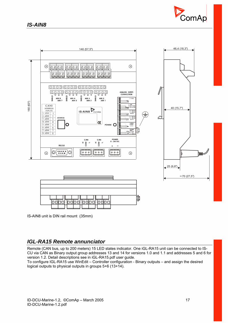
IS-AIN8 unit is DIN rail mount (35mm)
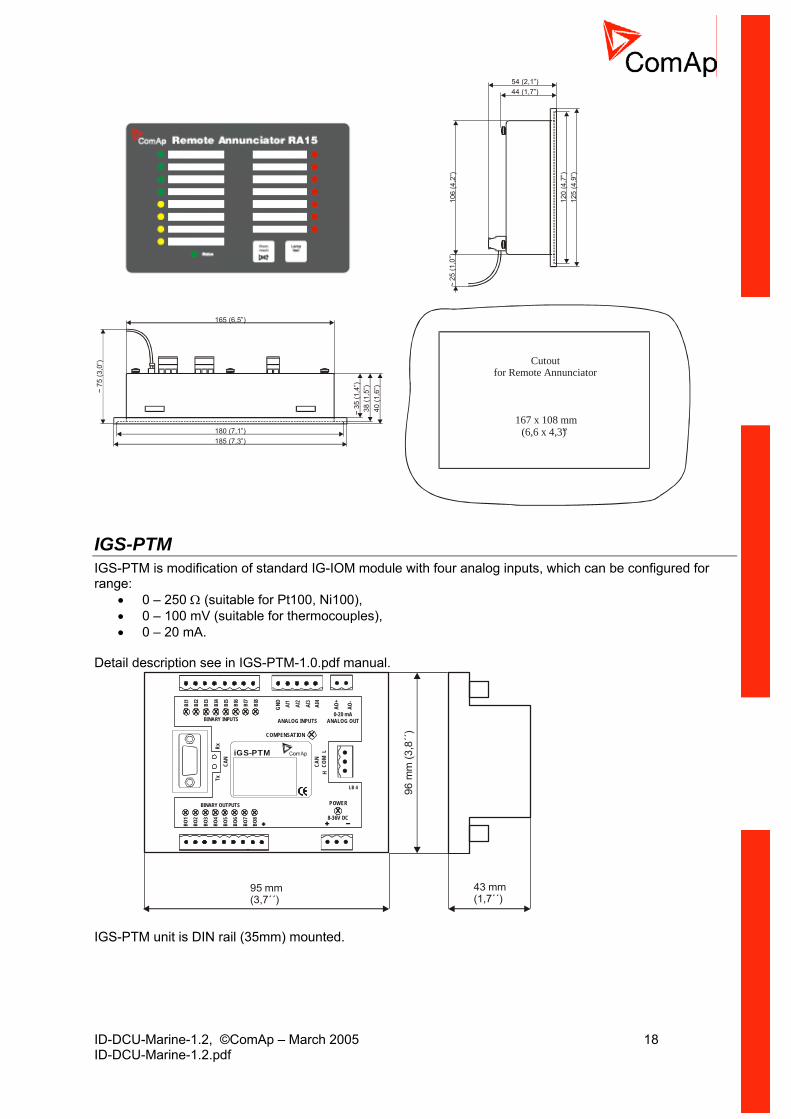
IGL-RA15 Remote annunciator Remote (CAN bus, up to 200 meters) 15 LED states indicator. One iGL-RA15 unit can be connected to IS-CU via CAN as Binary output group addresses 13 and 14 for versions 1.0 and 1.1 and addresses 5 and 6 for version 1.2. Detail descriptions see in iGL-RA15.pdf user guide. To configure IGL-RA15 use WinEdit – Controller configuration - Binary outputs – and assign the desired logical outputs to physical outputs in groups 5+6 (13+14).
ID-DCU-Marine-1.2, ©ComAp – March 2005 18 ID-DCU-Marine-1.2.pdf
165 (6,5”)
38(1
,5”)
40(1
,6”)~75
(3,0
”)
~35
(1,4
”)
180 (7,1”)185 (7,3”)
106
(4,2
”)
44 (1,7”)54 (2,1”)
~25
(1,0
”)
120
(4,7
”)12
5(4
,9”)
Cutoutfor Remote Annunciator
167 x 108 mm(6,6 x 4,3)”
IGS-PTM IGS-PTM is modification of standard IG-IOM module with four analog inputs, which can be configured for range:
• 0 – 250 Ω (suitable for Pt100, Ni100), • 0 – 100 mV (suitable for thermocouples), • 0 – 20 mA.
Detail description see in IGS-PTM-1.0.pdf manual.
95 mm(3,7´´)
43 mm(1,7´´)
96 m
m (3
,8´´)COMPENSATION
GND
POWER
8-36V DC
BINARY OUTPUTS
BINARY INPUTS ANALOG INPUTS
AI4
BI8
BI7
BI6
BI5
BI4
BI3
BI2
BI1
0-20 mA ANALOG OUT
BO8
BO1
BO2
BO3
BO4
BO5
BO6
BO7
CAN
RxTx
CAN
LH
COM
LB 4
AO-
AO+
iGS-PTM
IGS-PTM unit is DIN rail (35mm) mounted.

ID-DCU-Marine-1.2, ©ComAp – March 2005 19 ID-DCU-Marine-1.2.pdf
IG-MU
95 mm(3,7´´)
43 mm(1,7´´)
96 m
m (3
,8´´
)
iG-MU
RS 422 LB 6
RS 485
POWER8-36V DC
CAN CAN
RS 48
5 / R
S 42
2
RS 23
2RS
232
TxB
L HCO
M L HCO
M
TxA
RxB
RxA
COM
Indication LED: TxCAN, RxCAN Indicates data transfer on the CAN2 line. TxD, RxD Indicates data transfer on the RS232 line. RUN Lights when at least one IG/IS controller is present on the CAN2
(intercontroller) bus. Blinks when no unit is communicated on the CAN2 (intercontroller) bus.
PWR Lights All the time when power supply is present. Internal IG-MU jumpers
P1 P2 P3
P4
P1 … 2-nd local bridge P2 … Modbus jumper P3 … Boot jumper P4 … Switch between RS232 and RS485/RS422

ID-DCU-Marine-1.2, ©ComAp – March 2005 20 ID-DCU-Marine-1.2.pdf
IG-IB Internet bridge
95 mm(3,7´´)
43 mm(1,7´´)
96 m
m (3
,8´´
)
See Internet communicationIt is recommended to use IG-IB firmware version 2.0 IG-IB unit is DIN 35 mm rail mounted.
I-CB communication bridge
POWER8-36V DC
COM
RS 23
2
LB 4i-CB
95 mm(3,7´´)
43 mm(1,7´´)
96 m
m (3
,8´´)
I-CB (Communication bridge) is programmable CAN bus interface between InteliDrive (InteliSys) and Engine Control Unit (ECU) like MTU, CAT, Scania etc.. Engine values like RPM, Oil pressure and other are received from ECU via CAN and corresponding sensors are not needed on IS-CU. Use ICBEdit software for I-CB configuration.

ID-DCU-Marine-1.2, ©ComAp – March 2005 21 ID-DCU-Marine-1.2.pdf
Recommended wiring
ID-RPU wiring
14
BATT A BATT B+ + --
+24V
DC
0VD
C
Max
8 A
Max
8 A
2
2
n.o.n.c.
+ -
K17 K18I-RB16
9 9
1 2 3
16x
K1-K16
5x10
kohm
Hint: BW protection of the ID-RPU outputs Fuel solenoid and Stop solenoid is active in open state only. To avoid BW detection configure not wired inputs or outputs of ID-RPU as Not used by DriveConfig sw. Battery minus terminals are separated.

ID-DCU-Marine-1.2, ©ComAp – March 2005 22 ID-DCU-Marine-1.2.pdf
Complete system example
14
L H
H
-
A
B
12345678
HL
AB
CAN2
CAN1
IG-IBIG-MU
ID-COM
+
L
CAN2
+ -POWER
+ -POWER
J158
7
J193
9
L HL H
K17 K18I-RB16
9 9
1 2 3
16x
K1-K16
120
ohm
120 ohm
120
ohm
CAN2
59
HL
IS-BIN
LH
IS-AIN
LH
IGS-PTM
LH
120
ohm
+ -POWER
+ -POWER
+ -POWER
120 ohm
Complete system without RPU
14
L H
H
-
A
B
12345678
HL
AB
CAN2
CAN1
ID-COM
+
L
CAN2
J158
7
J193
9
K17 K18I-RB16
9 9
1 2 3
16x
K1-K16
120 ohm
120
ohm
CAN2
59
HL
IS-BIN
LH
IS-AIN
LH
IGS-PTM
LH
120
ohm
+ -POWER
+ -POWER
+ -POWER
120 ohm
IG-IBIG-MU
+ -POWER
+ -POWER
L HL H
120
ohm
ID-DCU-Marine-1.2, ©ComAp – March 2005 23 ID-DCU-Marine-1.2.pdf
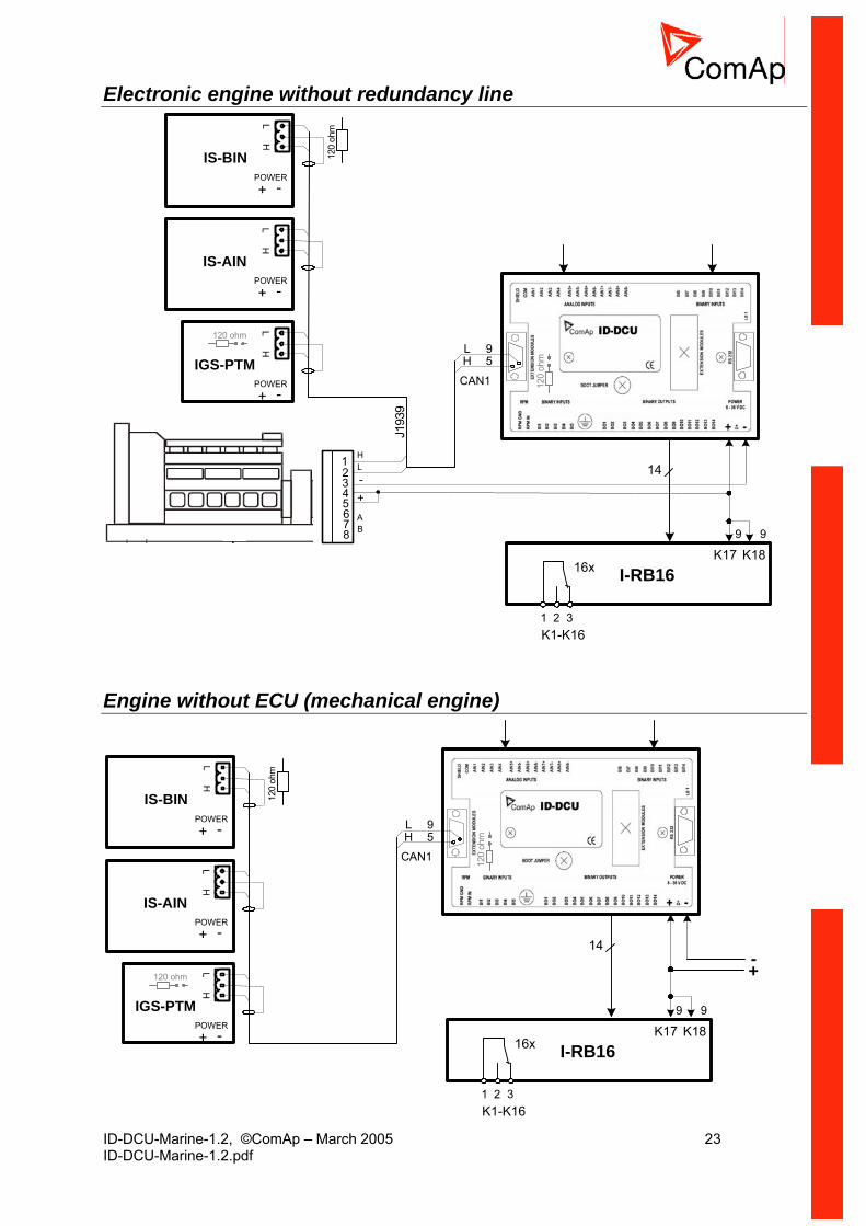
Electronic engine without redundancy line
14-
12345678
HL
AB
+
J193
9
K17 K18I-RB16
9 9
1 2 3
16x
K1-K16
CAN1
59
HL
120
ohm
IS-BIN
LH
IS-AIN
LH
IGS-PTM
LH
120
ohm
+ -POWER
+ -POWER
+ -POWER
120 ohm
Engine without ECU (mechanical engine)
14
K17 K18I-RB16
9 9
1 2 3
16x
K1-K16
CAN1
59
HL
120
ohm
IS-BIN
LH
IS-AIN
LH
IGS-PTM
LH
120
ohm
+ -POWER
+ -POWER
+ -POWER
120 ohm +-
ID-DCU-Marine-1.2, ©ComAp – March 2005 24 ID-DCU-Marine-1.2.pdf
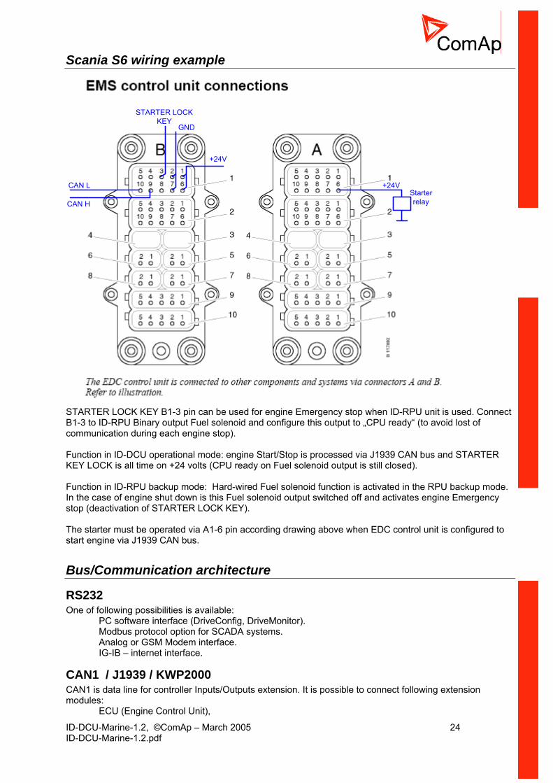
Scania S6 wiring example
CAN L
CAN H
STARTER LOCKKEY
+24V
GND
+24VStarterrelay
STARTER LOCK KEY B1-3 pin can be used for engine Emergency stop when ID-RPU unit is used. Connect B1-3 to ID-RPU Binary output Fuel solenoid and configure this output to „CPU ready“ (to avoid lost of communication during each engine stop). Function in ID-DCU operational mode: engine Start/Stop is processed via J1939 CAN bus and STARTER KEY LOCK is all time on +24 volts (CPU ready on Fuel solenoid output is still closed). Function in ID-RPU backup mode: Hard-wired Fuel solenoid function is activated in the RPU backup mode. In the case of engine shut down is this Fuel solenoid output switched off and activates engine Emergency stop (deactivation of STARTER LOCK KEY). The starter must be operated via A1-6 pin according drawing above when EDC control unit is configured to start engine via J1939 CAN bus.
Bus/Communication architecture
RS232 One of following possibilities is available:
PC software interface (DriveConfig, DriveMonitor). Modbus protocol option for SCADA systems. Analog or GSM Modem interface. IG-IB – internet interface.
CAN1 / J1939 / KWP2000 CAN1 is data line for controller Inputs/Outputs extension. It is possible to connect following extension modules:
ECU (Engine Control Unit),

ID-DCU-Marine-1.2, ©ComAp – March 2005 25 ID-DCU-Marine-1.2.pdf
IGS-PTM (8 BI, 8BO, 4AI, 1AO), IS-AIN (8AI), IS-BIN (16BI, 8BO).
Full physical CAN interface on ID-DCU is available, no ID-COM interface needed. Maximal CAN bus length is up to 200m.
CAN2 Inter-controller CAN for multiple engines applications. ID-COM module is necessary. It is possible to connect
ID-DCU controllers and/or IG-MU (Direct cable, analog modem or GSM modem interface) and/or IG-IB (Internet interface) and/or I-RD Marine remote display (Slave panel).
There are some limits for number of modules connected to CAN2 – see Rules for I-RD, IG-MU and IG-IB CAN address setting. The data rate is selectable in two levels: 250 kbd for 200 meters line and 62 kbd for 900 meters line.
Redundancy line (e.g.J1708) There are 2 datalinks in the system, one CAN SAE J1939 datalink and one SAE J1708/J1587 datalink. The J1939 datalink is used for control and monitoring data. The J1708/J1587 datalink is used for redundancy control and monitoring. The ID-COM interface is necessary to use for synchronous J1708/1587 data line.
CAN bus Connection rules CAN bus line must be connected in series, from one unit to the next (no star, no cable stubs, no branches) both ends must by the 120-ohm (internal or external) resistor terminated. Maximal CAN2 bus length is up to 200 meters when Basic settings: CAN bus mode = 32C or up to 900 meters when Basic settings: CAN bus mode = 8C. For CAN data cables details see chapter Technical data – Communication interface. CAN cable shielding connect to ID-DCU case. ID-DCU contains internal fix 120-ohm resistor on CAN1 bus. Use D SUB9 male connector: CAN H = 5, CAN L = 9, COMMON = 3 and 8. ID-DCU must be on the CAN bus end. IGS-PTM units contains internal jumper-removable 120 ohm resistor. To be sure check resistor presence by ohmmeter. Unit with internal resistor should be connected to the end of CAN2 line.

ID-DCU-Marine-1.2, ©ComAp – March 2005 26 ID-DCU-Marine-1.2.pdf
Getting started
How to install
General To ensure proper function:
Use grounding terminals. Wiring for binary inputs and analog inputs must not be lead parallel with high voltage/current cables. Analog and binary inputs should be provided with shielded cables, especially when length >3m.
Power supply To ensure proper function:
Use min. power supply cable of 1.5mm2
Maximum continuous DC power supply voltage is 36VDC. Maximum allowable power supply voltage is 39VDC. When there is a potential risk of the controller being subjected to conditions outside its capabilities, an outside protection device should be used. Hint: The InteliDrive controller should be grounded properly in order to protect against atmospheric discharges !!
+
+
Battery
-
-controller
HUGELOADS
STARTER
T1A
Power supply fusing 1 Amp fuse should be connected in-line with the battery positive terminal to the controller and modules. These items should never be connected directly to the starting battery. Fuse value and type depends on number of connected devices and wire length. Recommended fuse (not fast) type - T1A. Not fast due to internal capacitors charging during power up.
Binary output protections Do not connect binary outputs directly to DC relays without protection diodes. Use protection diodes even if the relays are not connected directly to controller outputs. I-RB16 relays include protection diodes.

ID-DCU-Marine-1.2, ©ComAp – March 2005 27 ID-DCU-Marine-1.2.pdf
+-
K1 K1K2 K2
24VDC+-
controllerT1A
Fuse
Fuse
Battery
DC relays
Example of controller protection
Grounding To ensure proper function:
The shortest possible piece of wire should be used when grounding the controller. Use cable min. 2,5mm2 . The “-“ terminal of the battery has to be properly grounded.
Magnetic pick-up To ensure proper function use a shielded cable.
+
Battery
-
GACSpeed Control Unit
ESD 5500
MAGNETICPICK-UP
CDSignal
Signal
+
+-
-PowerSupply
PowerSupply
GND
RPM-IN
controller
Be aware of interference signal from Speed governor when one speed pick-up is used.
ID-DCU-Marine-1.2, ©ComAp – March 2005 28 ID-DCU-Marine-1.2.pdf
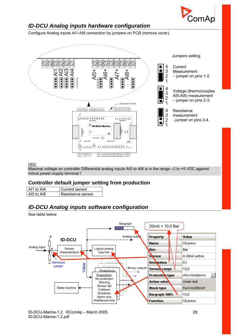
ID-DCU Analog inputs hardware configuration Configure Analog inputs AI1-AI8 connection by jumpers on PCB (remove cover).
Grounding Terminal
BOOT JUMPER
BINARY INPUTSRPM
BINARY INPUTSANALOG INPUTS
BINARY OUTPUTS POWER8 - 36 V DC
EXTE
NSIO
NMO
DULE
ID-R
PU
RS23
2
LB1
EXTE
NSIO
NMO
DULE
ID-C
OM
+ -RPM
GND
RPM
IN
BI1
BI2
BI3
BI4
BI5
SHIE
LDCO
M
D+BO1
BO2
BO3
BO4
BO5
BO8
BO6
BO12
BO13
BO14
BO9
BO7
BO10
BO11
AIN1
AIN2
AIN3
AIN4
AIN6
+
AIN5
+
AIN8
+AI
N8-
AIN6
-
AIN5
-
AIN7
+AI
N7-
BI6
BI7
BI8
BI9
BI10
BI11
BI13
BI12
BI14
1234
AI1
AI2
AI3
AI4
1234 AI
5+
AI6+
AI7+
AI8+
Jumpers setting
1234
Current Measurement – jumper on pins 1-2.
1234
Voltage (thermocouples AI5-AI8) measurement – jumper on pins 2-3.
1234
Resistance measurement - jumper on pins 3-4.
Hint: Maximal voltage on controller Differential analog inputs AI5 to AI8 is in the range –2 to +5 VDC against minus power supply terminal !
Controller default jumper setting from production AI1 to AI4 Current sensor AI5 to AI8 Resistance sensor
ID-DCU Analog inputs software configuration See table below
Protections:No protection
WarningSensor failColldownShutdownAlarm only
cord onlyHistRe
Protections:No protection
WarningSensor failColldownShutdoAlarm
HistReco
wn onlyrd only
Protections:No protection
WarningSensor fColldowShutdowAlarm on
HistRecord
ailnnly only
Sensorcharacteristics
+
RI
Analog input
Protections:No protection
WarningSensor failColldownShutdownAlarm only
HistRecord only
Logical analoginput list
Analog o
Bina
utput
ry outputs
State machine
Hardwarejumper
ID-DCU
Valu
e
Bargraph
20mA = 10,0 Bar
ID-DCU-Marine-1.2, ©ComAp – March 2005 29 ID-DCU-Marine-1.2.pdf
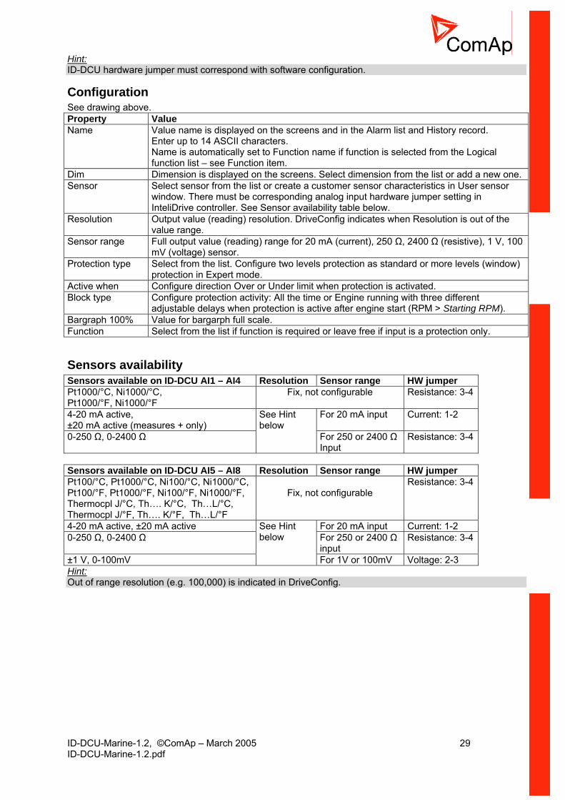
Hint: ID-DCU hardware jumper must correspond with software configuration.
Configuration See drawing above. Property Value Name Value name is displayed on the screens and in the Alarm list and History record.
Enter up to 14 ASCII characters. Name is automatically set to Function name if function is selected from the Logical function list – see Function item.
Dim Dimension is displayed on the screens. Select dimension from the list or add a new one. Sensor Select sensor from the list or create a customer sensor characteristics in User sensor
window. There must be corresponding analog input hardware jumper setting in InteliDrive controller. See Sensor availability table below.
Resolution Output value (reading) resolution. DriveConfig indicates when Resolution is out of the value range.
Sensor range Full output value (reading) range for 20 mA (current), 250 Ω, 2400 Ω (resistive), 1 V, 100 mV (voltage) sensor.
Protection type Select from the list. Configure two levels protection as standard or more levels (window) protection in Expert mode.
Active when Configure direction Over or Under limit when protection is activated. Block type Configure protection activity: All the time or Engine running with three different
adjustable delays when protection is active after engine start (RPM > Starting RPM). Bargraph 100% Value for bargarph full scale. Function Select from the list if function is required or leave free if input is a protection only.
Sensors availability Sensors available on ID-DCU AI1 – AI4 Resolution Sensor range HW jumper Pt1000/°C, Ni1000/°C, Pt1000/°F, Ni1000/°F
Fix, not configurable Resistance: 3-4
4-20 mA active, ±20 mA active (measures + only)
For 20 mA input Current: 1-2
0-250 Ω, 0-2400 Ω
See Hint below
For 250 or 2400 Ω Input
Resistance: 3-4
Sensors available on ID-DCU AI5 – AI8 Resolution Sensor range HW jumper Pt100/°C, Pt1000/°C, Ni100/°C, Ni1000/°C, Pt100/°F, Pt1000/°F, Ni100/°F, Ni1000/°F, Thermocpl J/°C, Th…. K/°C, Th…L/°C, Thermocpl J/°F, Th…. K/°F, Th…L/°F
Fix, not configurable
Resistance: 3-4
4-20 mA active, ±20 mA active For 20 mA input Current: 1-2 0-250 Ω, 0-2400 Ω For 250 or 2400 Ω
input Resistance: 3-4
±1 V, 0-100mV
See Hint below
For 1V or 100mV Voltage: 2-3 Hint: Out of range resolution (e.g. 100,000) is indicated in DriveConfig.

ID-DCU-Marine-1.2, ©ComAp – March 2005 30 ID-DCU-Marine-1.2.pdf
Configuration examples • Conversion from 4-20mA to 6,0 Bar Oil pressure sensor (Wrn+Sd protection and Oil pressure function)
• Conversion from ± 1V input to engine speed request 0 to 100% Step 1. Create new User sensor
Hint: HW configuration: CU 0-1V can be used for characteristics ± 1V, but this ± characteristics can be configured to AI5 to AI8 inputs only ! Sensor range (gray background) automatically follows the User sensor characteristics (zero value in drawing above is not important).
ID-DCU-Marine-1.2, ©ComAp – March 2005 31 ID-DCU-Marine-1.2.pdf
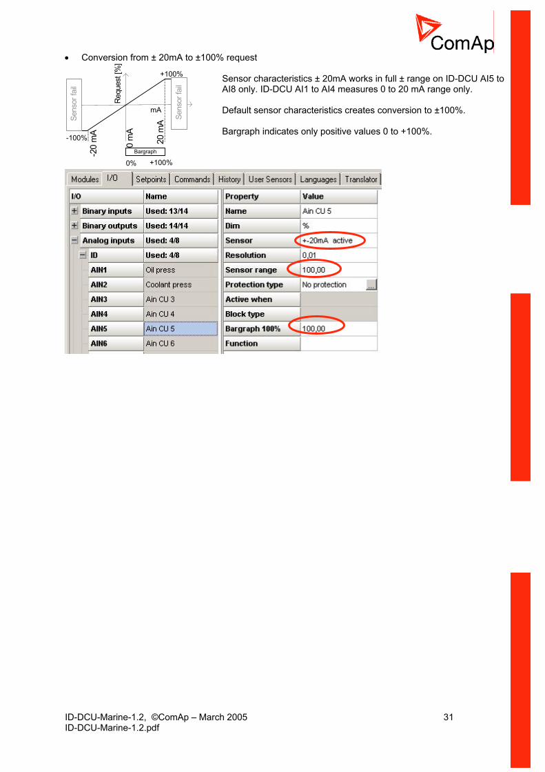
• Conversion from ± 20mA to ±100% request
Req
uest
[%]
-20
mA
20 m
A
+100%
mA
0 m
A-100%
Sens
or fa
il
Sens
or fa
il
Bargraph
0% +100%
Sensor characteristics ± 20mA works in full ± range on ID-DCU AI5 to AI8 only. ID-DCU AI1 to AI4 measures 0 to 20 mA range only. Default sensor characteristics creates conversion to ±100%. Bargraph indicates only positive values 0 to +100%.
ID-DCU-Marine-1.2, ©ComAp – March 2005 32 ID-DCU-Marine-1.2.pdf
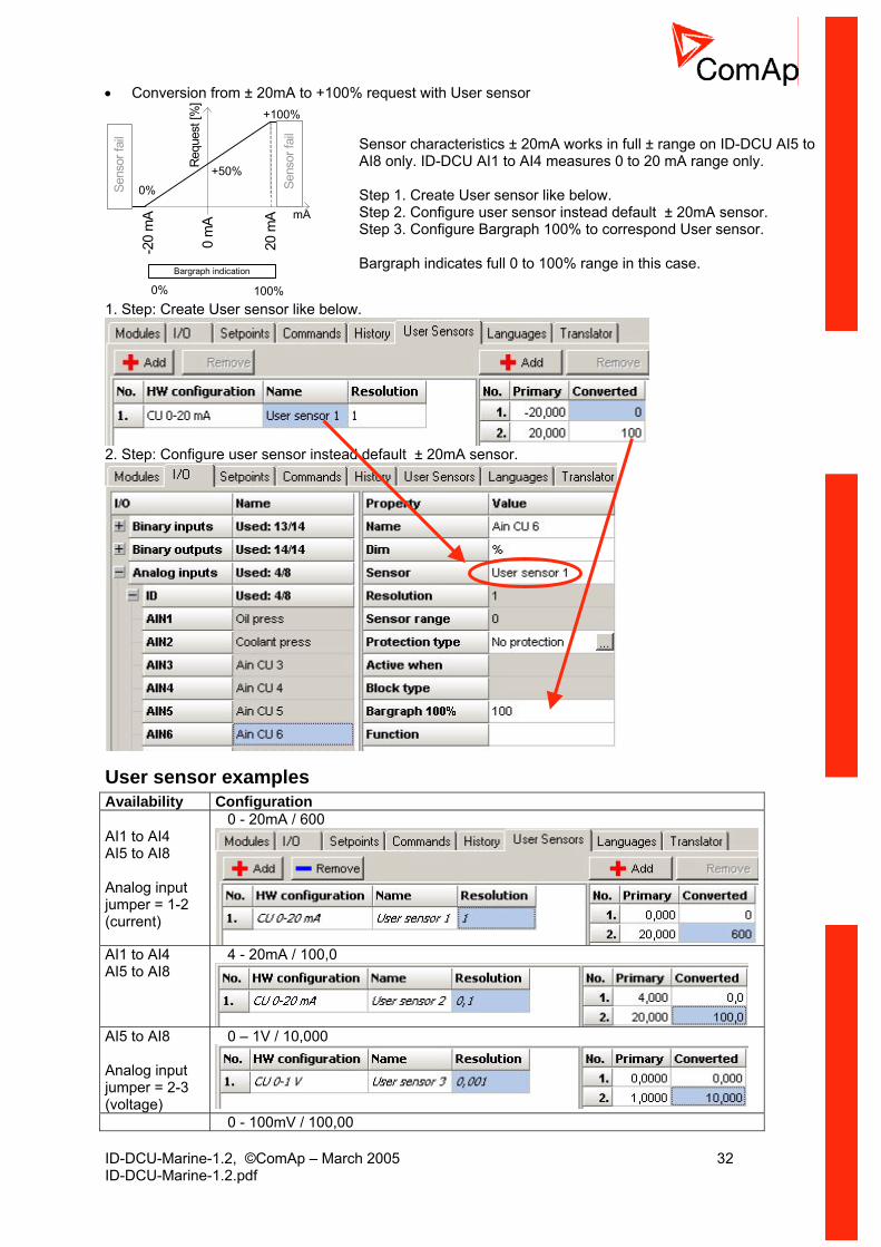
• Conversion from ± 20mA to +100% request with User sensor
-20
mA
20 m
A
+100%
mA0
mA
0%+50%R
eque
st [%
]
Sens
or fa
il
Sens
or fa
ilBargraph indication
0% 100%
Sensor characteristics ± 20mA works in full ± range on ID-DCU AI5 to AI8 only. ID-DCU AI1 to AI4 measures 0 to 20 mA range only. Step 1. Create User sensor like below. Step 2. Configure user sensor instead default ± 20mA sensor. Step 3. Configure Bargraph 100% to correspond User sensor. Bargraph indicates full 0 to 100% range in this case.
1. Step: Create User sensor like below.
2. Step: Configure user sensor instead default ± 20mA sensor.
User sensor examples Availability Configuration AI1 to AI4 AI5 to AI8 Analog input jumper = 1-2 (current)
0 - 20mA / 600
AI1 to AI4 AI5 to AI8
4 - 20mA / 100,0
AI5 to AI8 Analog input jumper = 2-3 (voltage)
0 – 1V / 10,000
0 - 100mV / 100,00

ID-DCU-Marine-1.2, ©ComAp – March 2005 33 ID-DCU-Marine-1.2.pdf
AI5 to AI8
AI1 to AI4 AI5 to AI8 Analog input jumper = 3-4 (resistance)
0 – 1200 ohm / 100
Hint: It is possible to set up to 30 points non-linear sensor characteristics. Connect external resistors (voltage divider) to extend input voltage range.
Hardware connection
Connection of ID-DCU analog inputs
ID-CU
CO
M-
PO
WE
R
AI4
AI3
AI2
AI1 AI6
-A
I6+
AI5
-A
I5+
AI8
-A
I8+
AI7
-A
I7+
A ll jumpers in position (3-4)
Standard connection of resistive sensors to ID-DCU analog inputs AI1 to AI8. The COM terminal must be always connected to the negative power terminal.
v
+
v+
-
CO
M-
PO
WE
R
AI1
(3-
4)
AI4
AI3
(2-
3)A
I2 (
1-2)
AI6
-A
I6+
AI5
-A
I5+
AI8
-A
I8+
AI7
-A
I7+
(3-4
)
(1-2
)
(1-2
)
(2-3
)
+
Different sensors connection to ID-DCU. AI configuration jumpers must be in corresponding position and corresponding DriveConfig configuration according to used sensor. Analog input common terminal COM has to be connected to ID minus Power supply terminal. Mixed connection of ID-DCU analog inputs: AI2, AI7 – current sensor AI1, AI5 – resistive sensor AI3, AI8 – voltage input AI6 – thermocouple (voltage) AI4 – Not used
ID-CU
COM
- PO
WER
AI4
AI3
AI2
AI1
AI6-
AI6+
AI5-
AI5+
AI8-
AI8+
AI7-
AI7+
All jumpers in position (3-4)
2x 4
70 o
hms
2x 4
70 o
hms
Mixed connection of InteliGen analog inputs: AI1, AI2, AI5, AI6 – resistive sensor AI3, AI7 – binary input AI4, AI8 – three state input Analog input common terminal COM has to be connected to ID minus Power supply terminal.
To ensure a proper function use shielded cables, especially for length over >3m.
Analog inputs on iS-AIN8 IS-AIN8 analog inputs can be configured to
ID-DCU-Marine-1.2, ©ComAp – March 2005 34 ID-DCU-Marine-1.2.pdf
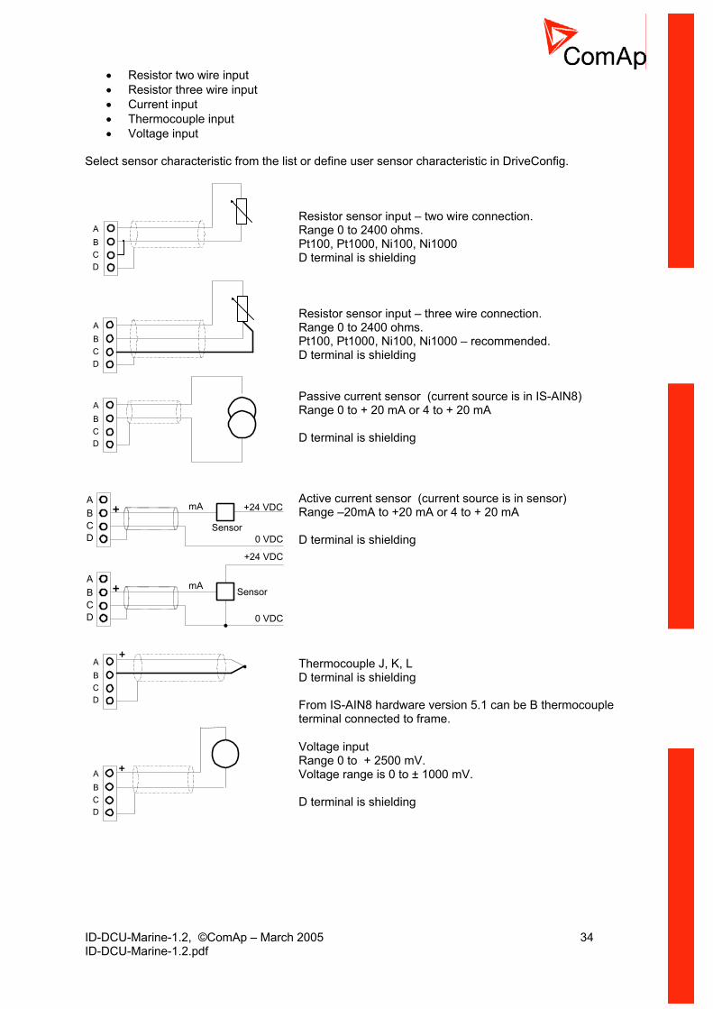
Sel s om the list or define user sensor characteristic in DriveConfig.
• Resistor two wire input • Resistor three wire input • Current input • Thermocouple input • Voltage input
ect ensor characteristic fr
Resistor sensor input – two wire connection. ange 0 to 2400 ohms. t100, Pt1000, Ni100, Ni1000
ABCD
RPD terminal is shielding
ABCD
ReR
sistor sensor input – three wire connection. ange 0 to 2400 ohms.
Pt100, Pt1000, Ni100, Ni1000 – recommended. D terminal is shielding
ABCD
(current source is in IS-AIN8) ge 0 to + 20 mA or 4 to + 20 mA
Passive current sensor Ran D terminal is shielding
ABCD
+ +24 VDC
Sensor
mA
0 VDC
ABCD
+
+24 VDC
0 VDC
SensormA
Active current sensor (current source is in sensor) Range –20mA to +20 mA or 4 to + 20 mA
D terminal is shielding
ABCD
+
Thermocouple J, K, L
shielding
can be B thermocouple ame.
D terminal is From IS-AIN8 hardware version 5.1 terminal connected to fr
ABCD
+
Voltage input Range 0 to + 2500 mV. Voltage range is 0 to ± 10
00 mV.
D terminal is shielding

ID-DCU-Marine-1.2, ©ComAp – March 2005 35 ID-DCU-Marine-1.2.pdf
ABCD
+
R1
R2
For 10V input voltage range connect external resistors R1, R2 and select sensor characteristic 10V. R1=10 Kohm, R2=2,7 Kohm. D terminal is shielding
Hint Thermocouples connected to IS-AIN8 hardware versions below 5.0 must be galvanically separated from the frame. If the thermocouples are connected to IS-AIN8, appropriate jumpers must be removed (see rear sticker).
Analog Sensor availability Table of supported sensors on various modules. Do not configure sensors, that are not supported on the input.
ID AI1-4 ID AI5-8 IGS-PTM IS-AIN8PT100/°C Y Y Y PT1000/°C Y Y Y NI100/°C Y Y Y NI1000/°C Y Y Y PT100/°F Y Y Y PT1000/°F Y Y Y NI100/°F Y Y Y NI1000/°F Y Y Y Thermo J/°C Y Y Thermo K/°C Y Y Thermo L/°C Y Y Thermo J/°F Y Y Thermo K/°F Y Y Thermo L/°F Y Y 4-20mA passive Y 4-20mA active Y Y Y Y 0-20mA passive Y +-20mA active Y Y Y Y 0-250ohm Y Y Y Y 0-2400ohm Y Y Y 0-2.4V Y +-1V Y Y 0-10V Y 0-100mV Y Y Y
Hint: Fahrenheit sensors are supported from IS-AIN8 of sw version 2.2 only.
Analog as Binary input To use Analog input as binary configure following characteristics:
Primary Converted 0 0 1000 1
Analog as three state binary input Open, close and failure (broken wire, short wire) states are detected. Threshold level is 750 Ω, failure is detected when circuit resistance is <10 Ω or > 2400 Ω.
ID-DCU-Marine-1.2, ©ComAp – March 2005 36 ID-DCU-Marine-1.2.pdf
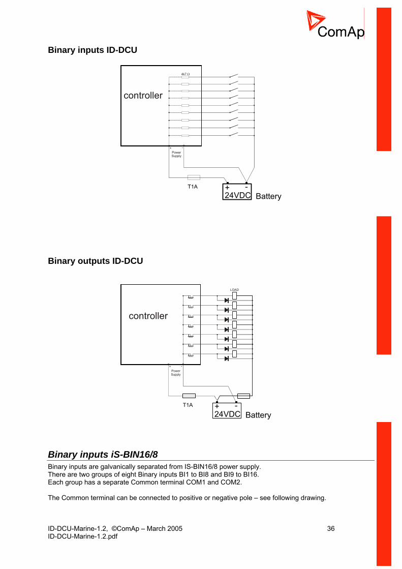
Binary inputs ID-DCU
controller
4k7 Ω
+ -PowerSupply
T1A
24VDC+ -
Battery
Binary outputs ID-DCU
controller
LOAD
+ -PowerSupply
24VDC+ -
BatteryT1A
Binary inputs iS-BIN16/8 Binary inputs are galvanically separated from IS-BIN16/8 power supply. There are two groups of eight Binary inputs BI1 to BI8 and BI9 to BI16. Each group has a separate Common terminal COM1 and COM2. The Common terminal can be connected to positive or negative pole – see following drawing.
ID-DCU-Marine-1.2, ©ComAp – March 2005 37 ID-DCU-Marine-1.2.pdf
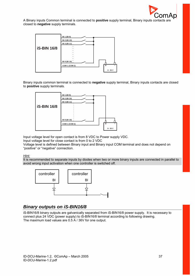
A Binary inputs Common terminal is connected to positive supply terminal, Binary inputs contacts are closed to negative supply terminals.
+8 - 36 V
-
iS-BIN 16/8
BI 1 (BI 9)
BI 2 (BI 10)
BI 3 (BI 11)
BI 8 (BI 16)
COM 1 (COM 2)
Binary inputs common terminal is connected to negative supply terminal, Binary inputs contacts are closed to positive supply terminals.
+8 - 36 V
-
iS-BIN 16/8
BI 1 (BI 9)
BI 2 (BI 10)
BI 3 (BI 11)
BI 8 (BI 16)
COM 1 (COM 2)
Input voltage level for open contact is from 8 VDC to Power supply VDC. Input voltage level for close contact is from 0 to 2 VDC Voltage level is defined between Binary input and Binary input COM terminal and does not depend on “positive” or “negative” connection. Hint: It is recommended to separate inputs by diodes when two or more binary inputs are connected in parallel to avoid wrong input activation when one controller is switched off.
controllerBIBI
controller
Binary outputs on iS-BIN16/8 iS-BIN16/8 binary outputs are galvanically separated from iS-BIN16/8 power supply. It is necessary to connect plus 24 VDC (power supply) to iS-BIN16/8 terminal according to following drawing. The maximum load values are 0.5 A / 36V for one output.

ID-DCU-Marine-1.2, ©ComAp – March 2005 38 ID-DCU-Marine-1.2.pdf
+8 - 36 V
-
iS-BIN 16/8BO 1
BO 8
0 V DC
24 V DC
Binary output separation In some special cases e.g. when Relays plus terminal is disconnected via EMERGENCY STOP contact, the binary outputs must be separated using diodes to avoid false Binary output LED indication. In the Example below when EMERGENCY STOP contact is opened, the BO3 LED should light (without separating diode SD3) even if the BO3 output is opened.
+
BO 3
BO 4
BO x
- POWER SUPPLY
EMERGENCYSTOP
+24VDC
0 VDC
iS-CUiS-BINiGS-PTMiG-IOM
SD3
SD4
IS-AIN8, IS-BIN8/16 address setting • Press Address button during IS-AIN8 power supply on to switch to addressing mode. • Then repeatedly press or keep pressed address button to adjust required address according to IS-CU
configuration. • After setting requested address, release the buttons and wait until the digits blink – it indicates write the
changed address to EEPROM memory. Hint: CAN address 0 disables corresponding CAN message (Group data are not send).
IS-AIN8, IS-BIN8/16 SW version check Let suppose IS-AIN8 of SW version 1.4. Shortly press address button. Following sequence appears on the display: number “1”, one second pause, number “4”, two second pause, number “1”, one second pause, number “4”, two second pause and finally IS-AIN8 actual address. Table of recommended CAN1 address setting on IS-AIN8 and IS-BIN16/8
CAN 1 Address CAN1 Address 1. iS-AIN8 1 Inputs Outputs 2. iS-AIN8 2 1. iS-BIN16/8 1 1 3. iS-AIN8 3 2. iS-BIN16/8 3 2 4. iS-AIN8 4 3. iS-BIN16/8 5 3 4. iS-BIN16/8 7 4
Table of corresponding address setting in WinEdit – during IS-CU configuration.
Address Address 1. iS-AIN8 1 Inputs Outputs 2. iS-AIN8 2 1. iS-BIN16/8 1, 2 1 3. iS-AIN8 3 2. iS-BIN16/8 3. 4 2 4. iS-AIN8 4 3. iS-BIN16/8 5, 6 3 4. iS-BIN16/8 7, 8 4

ID-DCU-Marine-1.2, ©ComAp – March 2005 39 ID-DCU-Marine-1.2.pdf
Hint: iS-BIN16/8 module has separate CAN1 addresses for binary inputs Group 1, Group 2 and binary outputs Group (total three addresses). The CAN1 address for BI Group 1 and for BO Group can be adjusted on the iS-BIN16/8. The address for BI Group 2 is set automatically to the address following after BI Group 1. Hint: CAN bus line has to be terminated by 120 ohm resistors on the both ends. For longer distances is recommended to connect CAN COM terminals between all controllers and cable shielding to the ground in one point. External units can be connected on the CAN bus line in any order, but line arrangement (no tails no star) is necessary. Recommended CAN bus data cables see in Chapter Technical data. IG-MU and IG-IB units are connected to CAN2 bus.
IGS-PTM and IGL-RA15 module connection It is possible to connect up to four IGS-PTM and one IGL-RA15 to one controller. IGS-PTM behaves like IS-AIN and IS-BIN modules in one unit. IGS-PTM and IGL-RA15units contain internal jumper removable 120-ohm resistor. Hint: Only IGS-PTM from hardware version 2.0 and software version 4.0 is compatible with InteliDrive.

ID-DCU-Marine-1.2, ©ComAp – March 2005 40 ID-DCU-Marine-1.2.pdf
Binary Inputs Hint: Binary inputs are not active in LOC mode.
Access lock If the input is closed
- Panel buttons START, STOP are inactive - No setpoints can be adjusted from controller front panel - Controller mode (e.g. OFF-AUX) cannot be changed - Fault reset, Horn reset buttons are still active - It is possible to list Values, Setpoints and History - Binary inputs function is without change
Active Access lock is indicated by “L” in the upper right corner of controller screen. Hint: Access lock does not protect Setpoints change, Mode change and START, STOP commands from Drive Monitor (direct or modem). To avoid unqualified changes of the selected setpoints or commands use password protection.
Remote lock If the input is closed following commands via serial line (e.g. from DriveMonitor or from remote display) are inactive:
- Remote engine start, stop commands - Fault reset and horn reset - Setpoints change
Engine can be started, stopped via Binary inputs (e.g. Remote start) or via front panel buttons. InteliDrive local / remote commands blocking overview Y = available; N = blocked Device Command Access lock Remote lock Local mode ID-DCU panel START N Y Y STOP N Y Y FLT RES Y Y Y HORN RES Y Y Y Setpoint change N Y Y Mode change N Y Y ID-DCU Bin Inputs Remote start Y Y N Remote stop Y Y N Blackout start Y Y N Remote OFF Y Y N Remote HBR Y Y N External modules Bin Inputs
...start/stop Y Y N
Remote OFF Y Y N Remote HBR Y Y N I-RD-CAN START N N N (serial line) STOP N N N FLT RES N N N HORN RES N N N Setpoint change N N N Mode change N N DriveMonitor START Y N N (serial line) STOP Y N N FLT RES Y Y N HORN RES Y Y N Setpoint change Y N N Mode change Y N N

ID-DCU-Marine-1.2, ©ComAp – March 2005 41 ID-DCU-Marine-1.2.pdf
Low Brightness Active Binary input switches ID-DCU display backlight between two adjustable intensity levels. Alternative intensity of the backlight can be set independently by ID-DCU panel buttons:
1. Hold Enter and press Page to switch to ID Info screen (from any measure screen) 2. Hold Enter and pres Up/Down arrow key to increase/decrease display brightness
The adjusted intensity is stored in nonvolatile memory. Hint: Both backlight levels are default (from production) set to maximum.
Force block Active input blocks protections that are configured as “Force Block”. Corresponding setpoint is ForceBlock del.
Fault reset Binary input for Alarm acknowledge (level sensitive) has the same function as controller front panel button Fault reset. Hint: There is separate acknowledge for ECU Alarms – see Binary input ECU FltReset (Enter+Fault reset keys from controller panel) .
Horn reset Binary input Horn reset is level sensitive.
Remote OFF Controller is switched to OFF mode if input is closed and back to previous mode after is opened. Input is not active in LOC mode. Active binary input Remote OFF is indicated by “L” character in the right up corner on ID_DCU screen. Hint: Remote OFF will switch controller to OFF mode even if the Access code or Remote lock is active or Controller mode is password protected.
Remote HRB (CMB only) Controller is switched to HRB mode if closed and back to previous mode if opened. Input is not active in LOC mode.
Emergency stop Engine Shut down activation, default configured as normally closed contact. Hint: Emergency stop must be configured to ID-RPU Binary input Emergency stop when ID-RPU unit is used. For highest safety it is recommended to connect second contact from Emergency stop to deactivate Fuel solenoid or activate Stop solenoid when Emergency stop is pushed.
Remote start External “edge sensitive” request for engine start. Binary input is active in all AUX, EME, HRB and PRP modes and inactive in Local mode. There is only one start attempt in AUX mode. Starting procedure is repeated in EME mode (MaxCrank time and CrankFail pause) until engine does not start. Unsuccessful start is recorded to Alarm list and History. The second edge on Binary input Remote start skips the Idle time when engine is running in Idle state. Binary input REMOTE START signal is equivalent to ID-DCU (I-RD Marine) front panel Start button.
Remote stop Engine stop request. The first edge changes engine state from running to cooling, the second edge stops engine (skip the rest of cooling). Binary input is inactive in Local mode. REMOTE STOP signal is equivalent to ID-DCU front panel Stop button.
ID-DCU-Marine-1.2, ©ComAp – March 2005 42 ID-DCU-Marine-1.2.pdf
Blackout start (AUX, EME, CMB-EME) External “edge sensitive” request for engine start. Input is active in AUX, EME and CMB-EME mode, inactive in Local or Harbour mode. Adjustable number of attempts (see setpoints Engine params: Crank attempts, MaxCrank time and Cranking pause).
Back up speed (PRP only) If input is active and Logical Analog input Requested RPM is not valid (out of range, sensor fail), Engine Requested RPM is set to Load sharing: Back up Speed value. Requested RPM = 0 when analog request is out of range and Binary input Back up speed is not active.
Fire speed (PRP only) If active, clutch is disconnected and Engine speed is set to Engine params: FireAlarmSpeed.
Rem clutch (PRP only) If active closes binary output Clutch connect – see Clutch connect (PRP only).
Startblocking Forces controller NotReady state (=disables engine start). It is active in LOC mode as well.
RunIndication1, RunIndication2, RunIndication3 Binary input can be used for engine running indication e.g. via Oil pressure contact. Active Running indication blocks engine start (to avoid starter damage). Engine running state = RPM > Engine params: Starting RPM or Analog input Oil pressure > Engine params: Starting Poil or Active Binary input Run indication1 or Active Binary input Run indication2 or Active Binary input Run indication3.
Nominal speed Skips Idle time and switch controller from Idle to running state when closed before Idle time is over.
Loaded (AUX, EME, CMB) Input can be used for engine Loaded state indication. Controller state Running is changed to Loaded when Binary input Loaded is closed in engine Running state – visible on controller front panel.
Emerg. manual Controller does not activate binary output Fuel solenoid when engine starter is activated externally.
EnClutchStart (PRP only) Binary input activates Engine start via clutch. Engine is started by the other running engine via closed clutch - binary output Clutch connect. See Load sharing: MaxClStrPer protection setpoint.
Sd override Blocks all protections except Over-speed and Emergency stop (=Sprinkler).
• All alarms are detected • Alarms are recorded on the controller Alarm list screen • Alarm are recorded into History • Enabled Active calls remains active • Controller front panel engine RED LED blinks or lights • Does not influence electronic engine via J1939
Engine remains running even if the Alarm indications above are active.
ID-DCU-Marine-1.2, ©ComAp – March 2005 43 ID-DCU-Marine-1.2.pdf
Speed down, Speed up The engine Requested RPM is decreased/increased when input is closed. Speed down has higher priority when both Up and Down inputs are active. RPM inc/dec rate is defined by setpoint Engine params: BI Speed ramp. Engine speed can be set by analog input Requested RPM or by BI Speed Up and Down. Following requested RPM initialization is valid when Analog input Requested RPM is not configured. Requested RPM (Idle) = 0. Inputs are active in LOC mode. Requested RPM (Running) = 50% for AUX, EME, CMB (ECU 50%=Nominal RPM). Requested RPM (Running) = 0% for PRP.
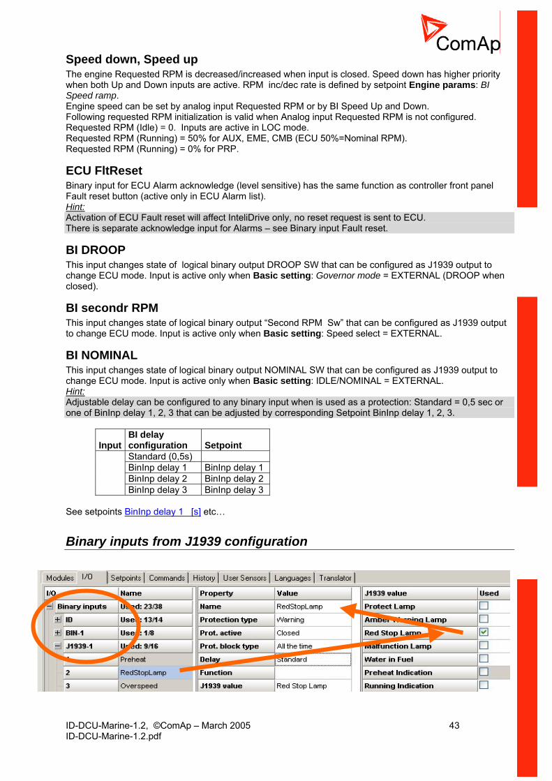
ECU FltReset Binary input for ECU Alarm acknowledge (level sensitive) has the same function as controller front panel Fault reset button (active only in ECU Alarm list). Hint: Activation of ECU Fault reset will affect InteliDrive only, no reset request is sent to ECU. There is separate acknowledge input for Alarms – see Binary input Fault reset.
BI DROOP This input changes state of logical binary output DROOP SW that can be configured as J1939 output to change ECU mode. Input is active only when Basic setting: Governor mode = EXTERNAL (DROOP when closed).
BI secondr RPM This input changes state of logical binary output “Second RPM Sw” that can be configured as J1939 output to change ECU mode. Input is active only when Basic setting: Speed select = EXTERNAL.
BI NOMINAL This input changes state of logical binary output NOMINAL SW that can be configured as J1939 output to change ECU mode. Input is active only when Basic setting: IDLE/NOMINAL = EXTERNAL. Hint: Adjustable delay can be configured to any binary input when is used as a protection: Standard = 0,5 sec or one of BinInp delay 1, 2, 3 that can be adjusted by corresponding Setpoint BinInp delay 1, 2, 3.
Input
BI delay configuration
Setpoint
Standard (0,5s) BinInp delay 1 BinInp delay 1 BinInp delay 2 BinInp delay 2
BinInp delay 3 BinInp delay 3 See setpoints BinInp delay 1 [s] etc…
Binary inputs from J1939 configuration
ID-DCU-Marine-1.2, ©ComAp – March 2005 44 ID-DCU-Marine-1.2.pdf
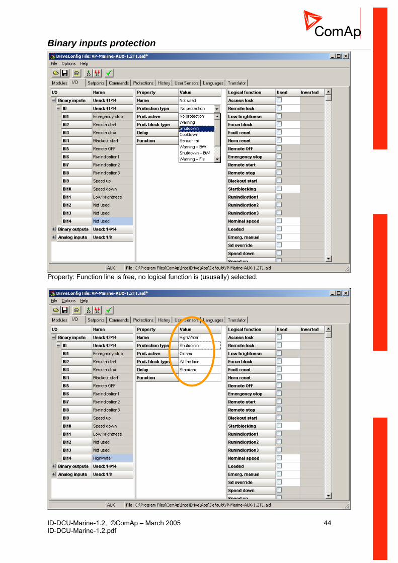
Binary inputs protection
Property: Function line is free, no logical function is (ususally) selected.

ID-DCU-Marine-1.2, ©ComAp – March 2005 45 ID-DCU-Marine-1.2.pdf
ID-DCU-Marine-1.2, ©ComAp – March 2005 46 ID-DCU-Marine-1.2.pdf
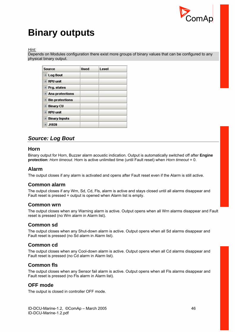
Binary outputs Hint: Depends on Modules configuration there exist more groups of binary values that can be configured to any physical binary output.
Source: Log Bout
Horn Binary output for Horn, Buzzer alarm acoustic indication. Output is automatically switched off after Engine protection: Horn timeout. Horn is active unlimited time (until Fault reset) when Horn timeout = 0.
Alarm The output closes if any alarm is activated and opens after Fault reset even if the Alarm is still active.
Common alarm The output closes if any Wrn, Sd, Cd, Fls, alarm is active and stays closed until all alarms disappear and Fault reset is pressed = output is opened when Alarm list is empty.
Common wrn The output closes when any Warning alarm is active. Output opens when all Wrn alarms disappear and Fault reset is pressed (no Wrn alarm in Alarm list).
Common sd The output closes when any Shut-down alarm is active. Output opens when all Sd alarms disappear and Fault reset is pressed (no Sd alarm in Alarm list).
Common cd The output closes when any Cool-down alarm is active. Output opens when all Cd alarms disappear and Fault reset is pressed (no Cd alarm in Alarm list).
Common fls The output closes when any Sensor fail alarm is active. Output opens when all Fls alarms disappear and Fault reset is pressed (no Fls alarm in Alarm list).
OFF mode The output is closed in controller OFF mode.
ID-DCU-Marine-1.2, ©ComAp – March 2005 47 ID-DCU-Marine-1.2.pdf
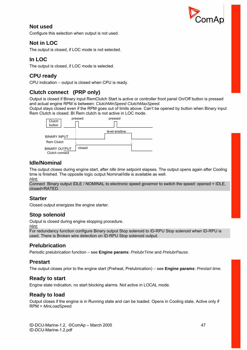
Not used Configure this selection when output is not used.
Not in LOC The output is closed, if LOC mode is not selected.
In LOC The output is closed, if LOC mode is selected.
CPU ready CPU indication – output is closed when CPU is ready.
Clutch connect (PRP only) Output is closed if Binary input RemClutch Start is active or controller front panel On/Off button is pressed and actual engine RPM is between: ClutchMinSpeed ClutchMaxSpeed. Output stays closed even if the RPM goes out of limits above. Can’t be opened by button when Binary input Rem Clutch is closed. BI Rem clutch is not active in LOC mode.
Clutchbutton
level ensitiveBINARY INPUTRem Clutch
BINARY OUTPUTClutch connect
closed
pressed pressed
Idle/Nominal The output closes during engine start, after Idle time setpoint elapses. The output opens again after Cooling time is finished. The opposite logic output Nominal/Idle is available as well. Hint: Connect Binary output IDLE / NOMINAL to electronic speed governor to switch the speed: opened = IDLE, closed=RATED.
Starter Closed output energizes the engine starter.
Stop solenoid Output is closed during engine stopping procedure. Hint: For redundancy function configure Binary output Stop solenoid to ID-RPU Stop solenoid when ID-RPU is used. There is Broken wire detection on ID-RPU Stop solenoid output.
Prelubrication Periodic prelubrication function – see Engine params: PrelubrTime and PrelubrPause.
Prestart The output closes prior to the engine start (Preheat, Prelubrication) – see Engine params: Prestart time.
Ready to start Engine state indication, no start blocking alarms. Not active in LOCAL mode.
Ready to load Output closes if the engine is in Running state and can be loaded. Opens in Cooling state. Active only if RPM > MinLoadSpeed.

ID-DCU-Marine-1.2, ©ComAp – March 2005 48 ID-DCU-Marine-1.2.pdf
Engine running It activates, when RPM raises above starting RPM and opens when RPM=0.
Ignition Ignition system activation/deactivation during start stop procedure.
Unload 1 sec (fix) pulse prior to transfer from Running to Cooling state.
Cooling Closes in cooling state, opens after engine stop.
Fuel solenoid Closed output opens the fuel solenoid. Adjustable to DIESEL or GAS. Hint: For redundancy function configure Binary output Fuel solenoid to ID-RPU Fuel solenoid when ID-RPU is used. There is Broken wire detection on ID-RPU Fuel solenoid output.
Cooling pump The output closes when engine starts and opens AfterCoolTime delayed after stop the engine.
Watchdog Indicates correctly running firmware when cycling on/off with 0,5 sec period.
Droop Sw The output is closed when setpoint Basic setting: Governor mode = DROOP or Governor mode = EXTERNAL and corresponding Binary input BI DROOP is closed. This logical output (Source) can be configured to corresponding J1939 output (e.g. Governor Mode in Volvo-MarineD12 Aux).
Second RPM Sw (AUX, EME, CMB) The output is closed when setpoint Basic setting: Speed select = Secondary or Speed select = EXTERNAL and corresponding Binary input “BI secondr RPM” is closed. This logical output (Source) can be configured to corresponding J1939 output (e.g. Frequency Select in Volvo-MarineD12 Aux) see an example below.
Second RPM Sw
Stop pulse 1 sec pulse is generated in the beginning of Stop procedure.
FaultResetPuls 1 sec pulse is generated after Fault reset button is closed.
Comm AIN fail Communication warning fail when any Analog input module address does not communicate (2s timeout).
ID-DCU-Marine-1.2, ©ComAp – March 2005 49 ID-DCU-Marine-1.2.pdf
Comm BIN fail Communication warning fail when any Binary input module address does not communicate (2s timeout).
Comm AOUT fail Communication warning fail when any Analog output module address does not communicate (2s timeout).
Comm BOUT fail Communication warning fail when any Binary output module address does not communicate (2s timeout).
Comm INCONfail Communication warning fail when any INCON module does not communicate (1s timeout).
Nominal/Idle Inverted function to binary output Idle/Nominal. The output closes during engine start, after Idle time setpoint elapses. The output closes again after Cooling time is finished.
Alarm blink Function is based on Binary output COMMON ALARM - stays closed when any alarm is active (at least one item in Alarm list) and opens for 2 sec when any new Alarm is activated. The first activation is delayed 2 sec. No Fault reset influence when at least one alarm is active. Output opens when Alarm list is empty.
Idle Sw The output is closed when setpoint Basic setting: Idle/Nominal = NOMINAL or Idle/Nominal = EXTERNAL and corresponding Binary input BI NOMINAL is closed. This logical output (Source) can be configured to corresponding J1939 output (e.g. Idle Speed Select in Volvo-MarineD12 Aux).
Logical 0 Constant value that can be configured to any output (e.g. CurrentGear in Volvo-PRP).
Logical 1 Constant value that can be configured to any output (e.g. CurrentGear in Volvo-PRP).
Operational Output closes with binary output Prestart and opens with binary output Cooling pump.
Source: RPU unit Values of ID-RPU unit are available (visible) only when ID-RPU module is selected. States does not activate Alarms.
FS-Status Binary output Fuel solenoid status when output is closed:
0 OK 1 Fail: Broken wire, short circuit, overheat
FS-Load Binary output Fuel solenoid status when output is opened:
0 OK 1 Fail: Broken wire
SS-Status Binary output Stop solenoid status when output is closed – see above.
SS-Load Binary output Stop solenoid status when output is opened – see above.
ID-DCU-Marine-1.2, ©ComAp – March 2005 50 ID-DCU-Marine-1.2.pdf
BinOut power Status of ID-RPU Fuel solenoid and Stop solenoid power supply terminal. Active when Power supply is connected.
Battery Fail Indicates that system is switched to Battery B.
RPU Control When closed ID-RPU module is active (after ID-DCU fail) for engine Sd and Over speed protection.
RPU Watchdog ID-RPU watchdog timer is over = ID-DCU fail when closed. Hint: Fuel and Stop solenoid Broken wire indication are available in the list of Prg.states - see below.
Source – Prg.states Programmable states (protections) list. Any item from the following list is activates Alarm list indicarion.
Wrn J1939 J1939 communication fail indication.
Bw RPU FuelSol ID-RPU Binary output Fuel solenoid - Broken wire indication.
Bw RPU StopSol ID-RPU Binary output Stop solenoid - Broken wire indication. Hint: Binary output Stop solenoid and Fuel solenoid broken wire is indicated in open state and in closed state when output current (load) is above 1 Amp.
Wrn J1587 J1587 communication fail indication.
ECU Alarm list Output is closed when at least one item is in ECU Alarm list.
UnivState 1 … Univ state 7 Universal states 1 to Universal states 7 indication. See Universal states description.
EcuDiagBlocked Output is closed when Basic setting: ECU diag = DISABLED.
Emergency stop Indication of Emergencu stop input.
Engine RPM Engine speed state indication. Output is clesed when no RPM is received from J1939 (sensor fail) or Overspeed or Under speed is detected.
Overload Active overload protection activation.
OtherCommEr Intercontroller communication error.
ID-DCU-Marine-1.2, ©ComAp – March 2005 51 ID-DCU-Marine-1.2.pdf
ChrgAlternFail Charger fail detection. D+ output current is limited to cca 300 mA. Guaranteed level for signal Charging OK = 90% of supply voltage. There are three possible conditions for stop engine cranking: Starting RPM, StartingPOil and D+ (when ENABLED). Starter goes off when any of these conditions becames valid.
Stop fail Engine stop fail indication. Stop fail: engine does not reach 0 RPM after stop command within Engine params: Stop time.
Overspeed Over speed indication.
Underspeed Under speed indication.
Pickup fail Pickup fail indication. Pickup fail: lost of RPM signal in running state (other running indication is active).
Battery flat ID-DCU controller reset during Cranking state.
Battery volt Indication when battery voltage (ID-DCU power supply) is out of Engine protect: Batt <V and Batt >V limits
WrnService Time Output is closed when Service time (count down) = 0. Hint: History record and Alarm list indication is activated as well.
Not lubricated The lubrication cycle (PrelubrTime) is not finished after controller Switch on or return from OFF mode.
Start fail The last start attempt was unsuccessful.
Harbour mode (CMB) Active Harbour mode indication.
OP RPMdep Out of Oil pressure RPM dependent limit indication.
CP RPMdep Out of Cooling pressure RPM dependent limit indication.
Batt A volt It is closed when the battery A voltage of RPU is out of limits : Engine protection: Batt >V, Batt <V, Batt V del.
Batt B volt It is closed when the battery B voltage of RPU is out of limits : Engine protection: Batt >V, Batt <V, Batt V del.
Wrn RPM diff It is closed when difference between Engine speed from ID-DCU and ID-RPU is higher than 100RPM.
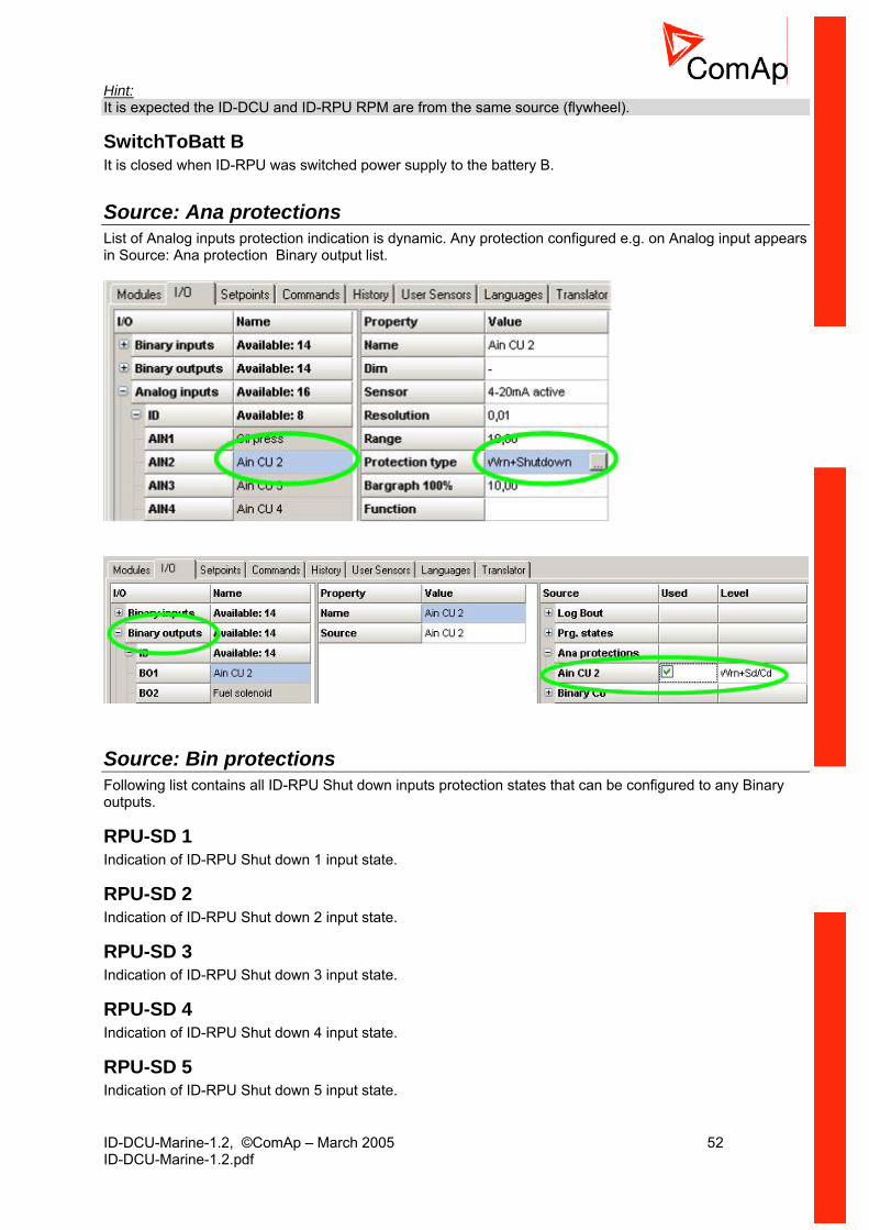
ID-DCU-Marine-1.2, ©ComAp – March 2005 52 ID-DCU-Marine-1.2.pdf
Hint: It is expected the ID-DCU and ID-RPU RPM are from the same source (flywheel).
SwitchToBatt B It is closed when ID-RPU was switched power supply to the battery B.
Source: Ana protections List of Analog inputs protection indication is dynamic. Any protection configured e.g. on Analog input appears in Source: Ana protection Binary output list.
Source: Bin protections Following list contains all ID-RPU Shut down inputs protection states that can be configured to any Binary outputs.
RPU-SD 1 Indication of ID-RPU Shut down 1 input state.
RPU-SD 2 Indication of ID-RPU Shut down 2 input state.
RPU-SD 3 Indication of ID-RPU Shut down 3 input state.
RPU-SD 4 Indication of ID-RPU Shut down 4 input state.
RPU-SD 5 Indication of ID-RPU Shut down 5 input state.

ID-DCU-Marine-1.2, ©ComAp – March 2005 53 ID-DCU-Marine-1.2.pdf
Source – Binary CU Binary CU list contains all ID-DCU binary inputs that can be configured to Binary outputs.
Source – RPU unit Following list contains ID-RPU Shut down inputs state that can be configured to Binary outputs.
RPU-SD 1 Indication of ID-RPU Shut down 1 input state.
RPU-SD 2 Indication of ID-RPU Shut down 2 input state.
RPU-SD 3 Indication of ID-RPU Shut down 3 input state.
RPU-SD 4 Indication of ID-RPU Shut down 4 input state.
RPU-SD 5 Indication of ID-RPU Shut down 5 input state.
Emergency stop RPU Indication of ID-RPU Emergency stop input state.
Source – Binary Inputs List (depend on modules configuration) contains all Extension modules binary inputs that can be configured to any Binary outputs.
Source – J1939 Following list contains all binary values received from J1939 that can be configured to Binary outputs. This list depends on selected ESF file. For more detail see corresponding engine specification.
Running Engine running state indication.
Overspeed Engine over speed indication.
OilPress Oil pressure out of limit indication.
OilTemp Oil temperature out of limit indication.
CoolantTemp Coolant temperature out of limit indication.
Coolant Level Coolant level out of limit indication.

ID-DCU-Marine-1.2, ©ComAp – March 2005 54 ID-DCU-Marine-1.2.pdf
Binary output to J1939 configuration: Source-Value
ID-DCU-Marine-1.2, ©ComAp – March 2005 55 ID-DCU-Marine-1.2.pdf
Logical analog inputs list LCD brightness Analog input for external LCD brightness setting (e.g. via potentiometer). Keyboard LCD brightness setting does not work when input is configured. Expected value is in the range 0 to 100%.
Engine speed RPM value from ECU - J1939.
Oil press Running indication and speed dependable protection in PRP. This value is indicated on the first controller screen.
Coolant temp This value is indicated on the first controller screen. Hint: Configure Oil pressure and Coolant temperature logical inputs to display values on the first controller screen.
Coolant pressure (PRP only) Running indication and speed dependable protection in PRP
Requested RPM AI influences directly Engine Requested RPM register when configured without ramp. In the case of sensor fail (out of range) is Sped request = 0 for PRP and 50% (=Nominal RPM) for AUX, EME, HRB.
Engine torque (PRP only) Actual engine torque in %, received from J1939.
Cyl temp 1 … Cyl temp 16 Analog inputs for engine Cylinder temperature measuring.
Obligatory J1939 items Engine Binary outputs Analog inputs Cummins MODBUS
not supported by ID
Scania S6 Allspeed
Engine Start – LBO Starter Engine Stop – LBO StopPuls/LBO StopSolenoid
Engine Speed – LAI Engine Speed
Scania S6 Singlespeed
Engine Start – LBO Starter Engine Stop – LBO StopPuls/LBO StopSolenoid
Engine Speed – LAI Engine Speed
Standard J1939 engine
-
Volvo Aux Start Request – LBO Starter Stop Request – LBO StopPuls
Engine Speed – LAI Engine Speed
Volvo Prop Start Request – LBO Starter Stop Request – LBO StopPuls
Engine Speed – LAI Engine Speed
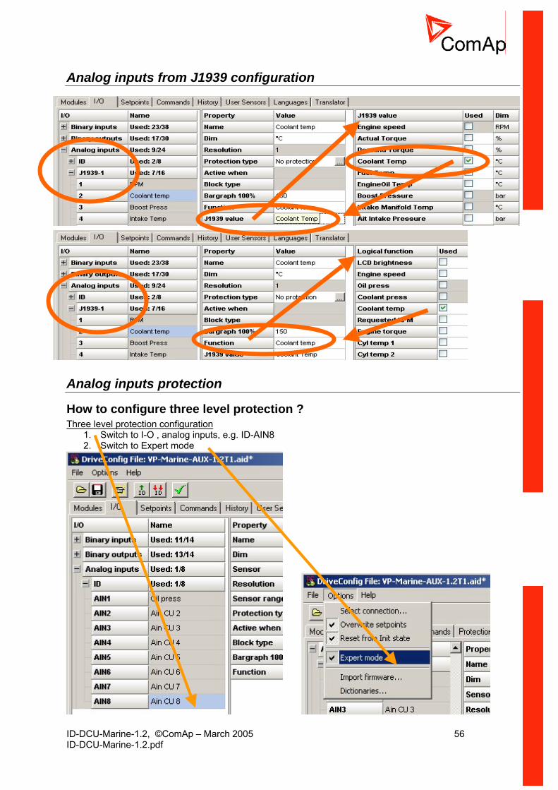
ID-DCU-Marine-1.2, ©ComAp – March 2005 56 ID-DCU-Marine-1.2.pdf
Analog inputs from J1939 configuration
Analog inputs protection
How to configure three level protection ? Three level protection configuration
1. Switch to I-O , analog inputs, e.g. ID-AIN8 2. Switch to Expert mode

ID-DCU-Marine-1.2, ©ComAp – March 2005 57 ID-DCU-Marine-1.2.pdf
3. Configure standard two level protection
Expert field is now empty. This field is visible in Expert mode only. Standard two level protection (ID-AIN8) example:
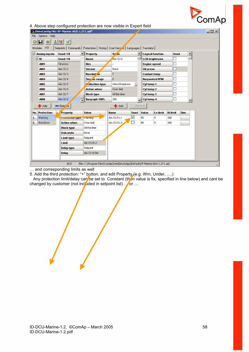
ID-DCU-Marine-1.2, ©ComAp – March 2005 58 ID-DCU-Marine-1.2.pdf
4. Above step configured protection are now visible in Expert field
… and corresponding limits as well 5. Add the third protection: “+” button, and edit Property (e.g. Wrn, Under, ….) Any protection limit/delay can be set to Constant (then value is fix, specified in line below) and cant be changed by customer (not included in setpoint list) … or …
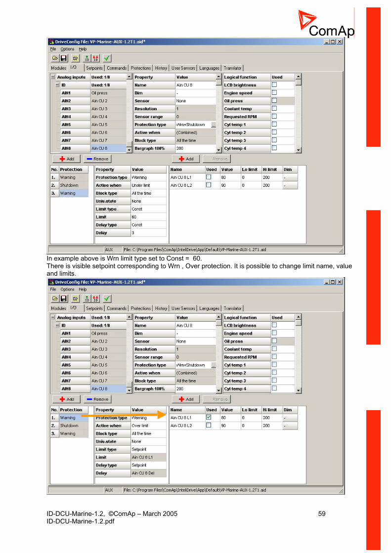
ID-DCU-Marine-1.2, ©ComAp – March 2005 59 ID-DCU-Marine-1.2.pdf
In example above is Wrn limit type set to Const = 60. There is visible setpoint corresponding to Wrn , Over protection. It is possible to change limit name, value and limits.

ID-DCU-Marine-1.2, ©ComAp – March 2005 60 ID-DCU-Marine-1.2.pdf
Use “+” button to add new limit for the third (Wrn, Under) protection. Name “Limit3” can be changed. Limit and Delay type must be in this case set to “Setpoint”
Use “+” button to add Delay setpoint and set/change name value and limits.
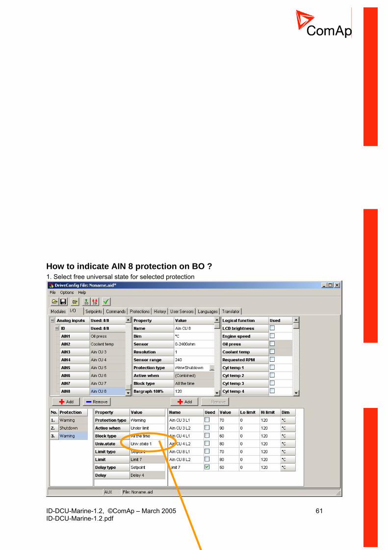
ID-DCU-Marine-1.2, ©ComAp – March 2005 61 ID-DCU-Marine-1.2.pdf
How to indicate AIN 8 protection on BO ? 1. Select free universal state for selected protection
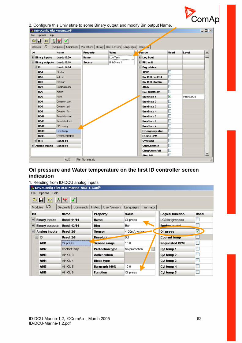
ID-DCU-Marine-1.2, ©ComAp – March 2005 62 ID-DCU-Marine-1.2.pdf
2. Configure this Univ state to some Binary output and modify Bin output Name.
Oil pressure and Water temperature on the first ID controller screen indication 1. Reading from ID-DCU analog inputs
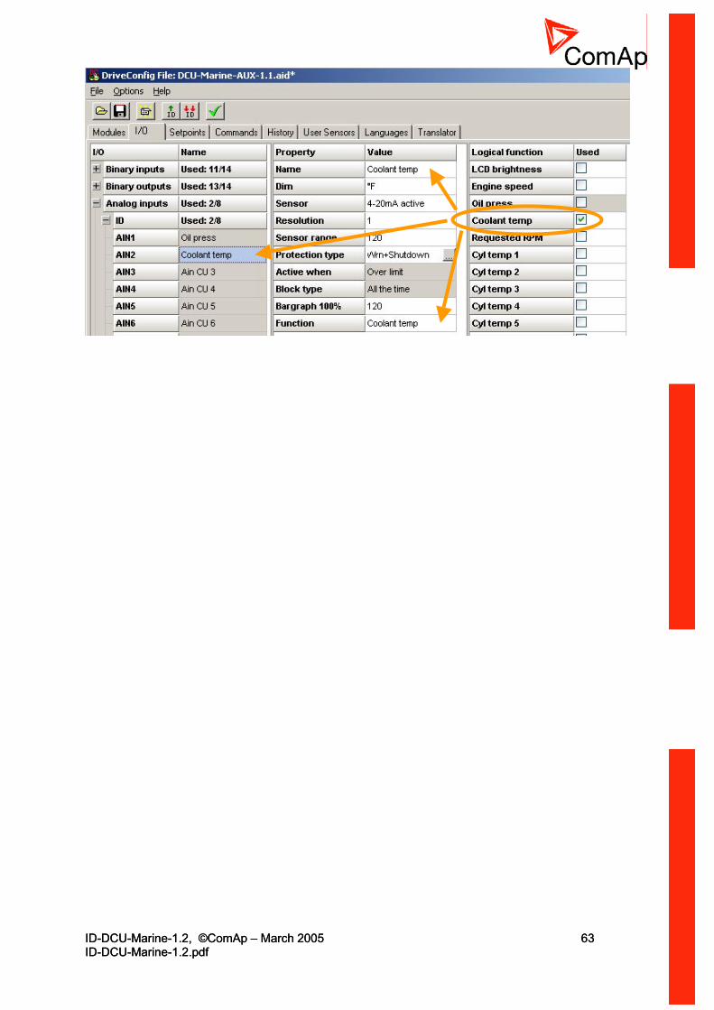
ID-DCU-Marine-1.2, ©ComAp – March 2005 63 ID-DCU-Marine-1.2.pdf
ID-DCU-Marine-1.2, ©ComAp – March 2005 63 ID-DCU-Marine-1.2.pdf

ID-DCU-Marine-1.2, ©ComAp – March 2005 64 ID-DCU-Marine-1.2.pdf
2. Reading form J1939 J1939 value
logical function
Please note there can be configured Protection as well.

ID-DCU-Marine-1.2, ©ComAp – March 2005 65 ID-DCU-Marine-1.2.pdf
Analog outputs Any of values from the Source list can be configured to any Analog output. The default Lo limit and Hi limit can be modified in DriveConfig. Lo limit corresponds to 0 mA output and Hi limit corresponds to 20 mA output. Following is example of transfer characteristics 0 - 100% to 0 – 20 mA.
0 mA
20 mA
Lo limit Hi limit0 100
Following is example of transfer characteristics 0 - 100% to 4 – 20 mA.
4 mA
20 mA
Lo limit Hi limit-25 100
Hint: Physical analog output 0 to 20 mA is available on IGS-PTM (from software version 4.0) extension unit only. Adjust corresponding negative Lo limit to obtain 4 – 20 mA output characteristics.
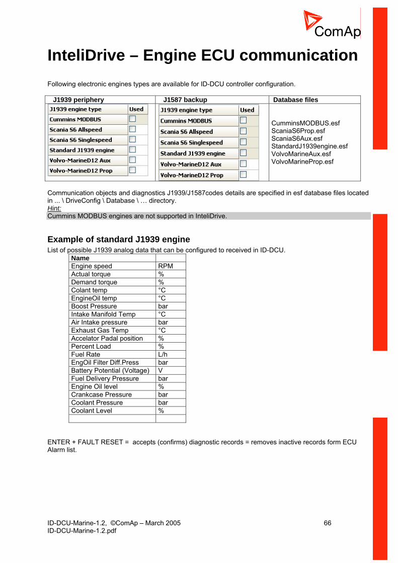
ID-DCU-Marine-1.2, ©ComAp – March 2005 66 ID-DCU-Marine-1.2.pdf
InteliDrive – Engine ECU communication Following electronic engines types are available for ID-DCU controller configuration. J1939 periphery J1587 backup Database files
CumminsMODBUS.esf ScaniaS6Prop.esf ScaniaS6Aux.esf StandardJ1939engine.esf VolvoMarineAux.esf VolvoMarineProp.esf
Communication objects and diagnostics J1939/J1587codes details are specified in esf database files located in ... \ DriveConfig \ Database \ … directory. Hint: Cummins MODBUS engines are not supported in InteliDrive.
Example of standard J1939 engine List of possible J1939 analog data that can be configured to received in ID-DCU.
Name Engine speed RPM Actual torque % Demand torque % Colant temp °C EngineOil temp °C Boost Pressure bar Intake Manifold Temp °C Air Intake pressure bar Exhaust Gas Temp °C Accelator Padal position % Percent Load % Fuel Rate L/h EngOil Filter Diff.Press bar Battery Potential (Voltage) V Fuel Delivery Pressure bar Engine Oil level % Crankcase Pressure bar Coolant Pressure bar Coolant Level %
ENTER + FAULT RESET = accepts (confirms) diagnostic records = removes inactive records form ECU Alarm list.
ID-DCU-Marine-1.2, ©ComAp – March 2005 67 ID-DCU-Marine-1.2.pdf
Setpoints
Password There are three levels of password protection. 0. User level allows change of of non-protected setpoints only 1. Operator level allows change of setpoints protected by Operator level 2. Master level allows change of setpoints protected by Operator and Master level 3. Supervisor highest level allows all setpoints or configuration changes, firmware upgrade. Hint: The asterisk mark “*” appears before a setpoint name (on controller screen) if the setpoint is password protected. The asterisk mark is removed only when the password is set from controllers front panel. The asterisk mark is still visible on controller screen even if the password is set from DriveMonitor. Even though one level may have been set from the front panel, the affected setpoints are not accessible from DriveMonitor (direct or Modem) until this level is set in DriveMonitor (direct or Modem). Setpoints opened from front panel are automatically closed 15 minutes after the last key has been depressed or when wrong value of setpoint is set. It is possible to protect remote Start, Stop commands from DriveMonitor as well. This three level command protection can be configured from DriveConfig.
EnterPassword Password is a four-digit number. Only setpoints associated with the entered password level can be modified. Use ↑ or ↓ to select the desired password and then hit enter.
ChangePassword 1
ChangePassword 2
ChangePassword 3 Hint: Any password can be changed once that level password or higher has been entered. To change password protection:
Open DriveConfig Select Setpoints window Set desired protection level: 0 or 1 or 2 or 3
Access code • Can be changed from DriveMonitor software only (Monitor – Change Access code). • Has to be set before remote modem or SMS connection is opened. • Can be up to 16 ASCII characters
At first Password3 has to be entered before the new Access code can be changed.
Engine commands and Statistics protection Commands (Engine cmd) password protection protects Start, Stop, Horn reset, Fault reset commands from DriveMonitor direct, modem or GSM modem connection. Selected Command password level 0, 1, 2, 3 is valid for all engine commands. Separately can be protected statistic commands: ClearStatistics, SetSucc starts, EngRun hours, SetUnsuc starts. To set commands protection from DriveConfig:
Open DriveConfig Select Commands window Set Password = 0 (no protection) or level 1 or 2 or 3

ID-DCU-Marine-1.2, ©ComAp – March 2005 68 ID-DCU-Marine-1.2.pdf
Hint: All setpoints below can be modified from Remote panel or DriveMonitor as well.
Basic settings
Engine name User defined name, used for InteliDrive controller identification at remote phone or mobile connection. Engine name is max 14 characters long and have to be entered manually using DriveConfig software. Hint:Engine name is not changed when new archive is loaded. Check Engine name after firmware upgrade.
Chassis number [0000000000000] This ASCII string is visible on controller INFO screen, maximal length is up to 13 characters.
Mode ID [ OFF, AUX ] Mode ID [ OFF, EME ] Mode ID [ OFF, EME, HRB ] Mode ID [ OFF, PRP ] Equivalent to Controller mode changes by MODE→ or ←MODE buttons. Hint: Mode change can be separately password protected. Mode can be changed by binary input Remote OFF or Remote HRB .
Gear teeth [-] Number of teeth on the engines flywheel for the pick-up. Setpoint is used for both ID-DCU and ID-RPU RPM calculation. Setpoint (RPM pickup measuring) is ignored when RPM is received via J1939. Step: 1 Range: 1 – 500
Nominal RPM [RPM] Nominal engine speed, base for Over-speed protection limit and Requested RPM % calculation. Step: 1 RPM Range: 30 – 4000 RPM Hint: Nominal RPM must correspond to 100% Throttle position in ECU for correct Load sharing function in PRP application.
Governor mode [ ISOCH, DROOP, EXTERNAL ] Activates/deactivates the logical binary output DROOP SW, that can be configured as J1939 output to switch ECU mode. EXTERNAL: ISOCH/DROOP mode is switched via Binary input BI DROOP (DROOP when closed).

ID-DCU-Marine-1.2, ©ComAp – March 2005 69 ID-DCU-Marine-1.2.pdf
Idle/Nominal [ IDLE, NOMINAL, EXTERNAL ] Activates/deactivates the logical binary output NOMINAL SW, that can be configured as J1939 output to switch ECU. EXTERNAL: IDLE/NOMINAL mode is switched via Binary input BI NOMINAL (NOMINAL when closed).
Basic settings: Idle/NominalIDLE
NOMINAL
EXTERNAL
Open = IDLEClosed=NOMINAL
BI NOMINAL
NOMINAL SW
Logical binaryoutput
Source J1939 value
Idle speed select J1939ECU
Speed select [ PRIMARY, SECONDARY, EXTERNAL ] Activates/deactivates the logical binary output “Secondary Sw” see Logical BO in table below. This output can be configured to J1939 output to switch ECU Nominal RPM. EXTERNAL: PRIMARY / SECONDARY Nominal RPM is selected via Binary input “BI Secondary Sw” – see Logical BI in table below.
Setpoint name Setpoint setting Logical BO Logical BI Governor mode ISOCHR / DROOP /
EXTERNAL Droop Sw BI Droop
Speed select PRIMARY / SECONDARY / EXTERNAL
Secondary Sw
BI Secondary
Idle/Nominal IDLE / NOMINAL / EXTERNAL
Nominal Sw BI Idle
Hint: Basic setting: Nominal RPM must correspond to ECU Nominal RPM for 100% Throttle position in PRP and 50% in AUX, EME, CMB.
ECU Diag [ ENABLED, DISABLED] Alarm list indication ECU Diag disabled is indicated when ECU diagnostics is disabled.
Contr. addr (1 .. 32) [-] Controller identification number. Each engine in the group has to have its own unique number. Default value is 1. Hint: The InteliDrive Contr. addr must correspond to DriveMonitor or DriveConfig communication setup setting when opening Direct or Modem connection.
RS232 mode [ STANDARD / MODBUS ] Communication protocol selection. STANDARD: InteliDrive (DriveConfig, DriveMonitor, Remote panel) communication protocol. MODBUS: Modbus RTU protocol. Hint: Detail Modbus protocol description include some examples see in InteliGen Communication guide.
CAN bus mode [ 32C / 8C ] Inter-controller, I-RD-CAN, IG-MU, IG-IB CAN2 bus speed selection. 32C: High speed CAN (250 kbps) applicable up to 32 controllers, CAN bus limited up to 200 meters. 8C: Low speed CAN (50 kbps) applicable up to 8 controllers, CAN bus limited up to 900 meters. Hint:
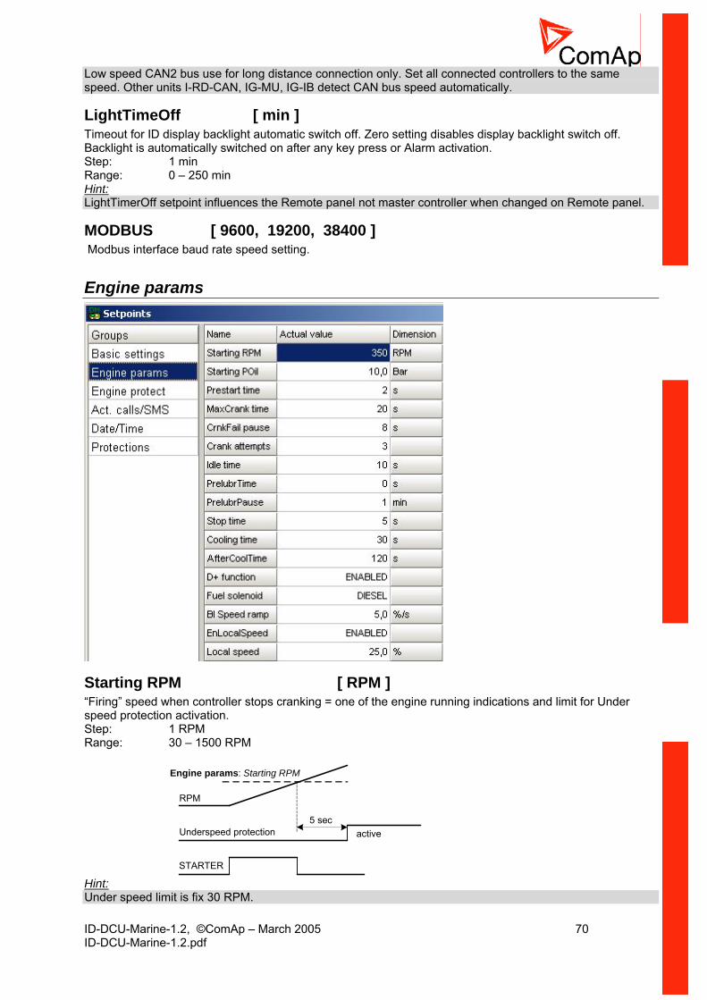
ID-DCU-Marine-1.2, ©ComAp – March 2005 70 ID-DCU-Marine-1.2.pdf
Low speed CAN2 bus use for long distance connection only. Set all connected controllers to the same speed. Other units I-RD-CAN, IG-MU, IG-IB detect CAN bus speed automatically.
LightTimeOff [ min ] Timeout for ID display backlight automatic switch off. Zero setting disables display backlight switch off. Backlight is automatically switched on after any key press or Alarm activation. Step: 1 min Range: 0 – 250 min Hint: LightTimerOff setpoint influences the Remote panel not master controller when changed on Remote panel.
MODBUS [ 9600, 19200, 38400 ] Modbus interface baud rate speed setting.
Engine params
Starting RPM [ RPM ] “Firing” speed when controller stops cranking = one of the engine running indications and limit for Under speed protection activation. Step: 1 RPM Range: 30 – 1500 RPM
Underspeed protection
RPM
active5 sec
STARTER
Engine params: Starting RPM
Hint: Under speed limit is fix 30 RPM.
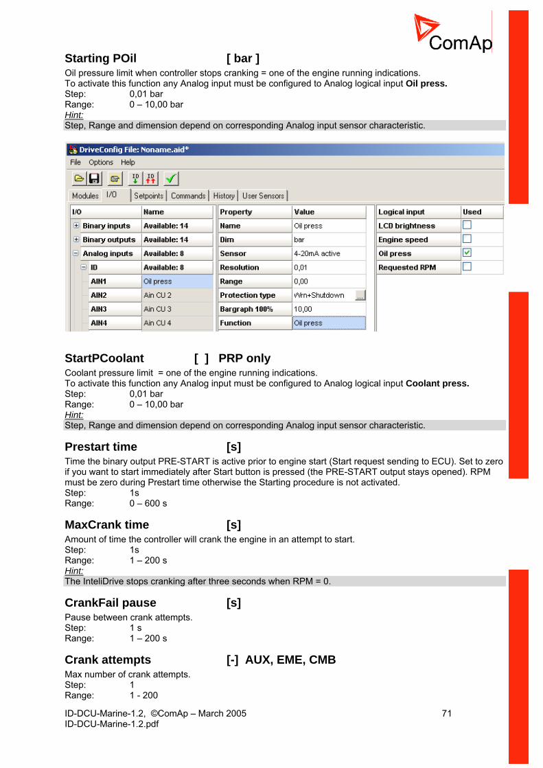
ID-DCU-Marine-1.2, ©ComAp – March 2005 71 ID-DCU-Marine-1.2.pdf
Starting POil [ bar ] Oil pressure limit when controller stops cranking = one of the engine running indications. To activate this function any Analog input must be configured to Analog logical input Oil press. Step: 0,01 bar Range: 0 – 10,00 bar Hint: Step, Range and dimension depend on corresponding Analog input sensor characteristic.
StartPCoolant [ ] PRP only Coolant pressure limit = one of the engine running indications. To activate this function any Analog input must be configured to Analog logical input Coolant press. Step: 0,01 bar Range: 0 – 10,00 bar Hint: Step, Range and dimension depend on corresponding Analog input sensor characteristic.
Prestart time [s] Time the binary output PRE-START is active prior to engine start (Start request sending to ECU). Set to zero if you want to start immediately after Start button is pressed (the PRE-START output stays opened). RPM must be zero during Prestart time otherwise the Starting procedure is not activated. Step: 1s Range: 0 – 600 s
MaxCrank time [s] Amount of time the controller will crank the engine in an attempt to start. Step: 1s Range: 1 – 200 s Hint: The InteliDrive stops cranking after three seconds when RPM = 0.
CrankFail pause [s] Pause between crank attempts. Step: 1 s Range: 1 – 200 s
Crank attempts [-] AUX, EME, CMB Max number of crank attempts. Step: 1 Range: 1 - 200
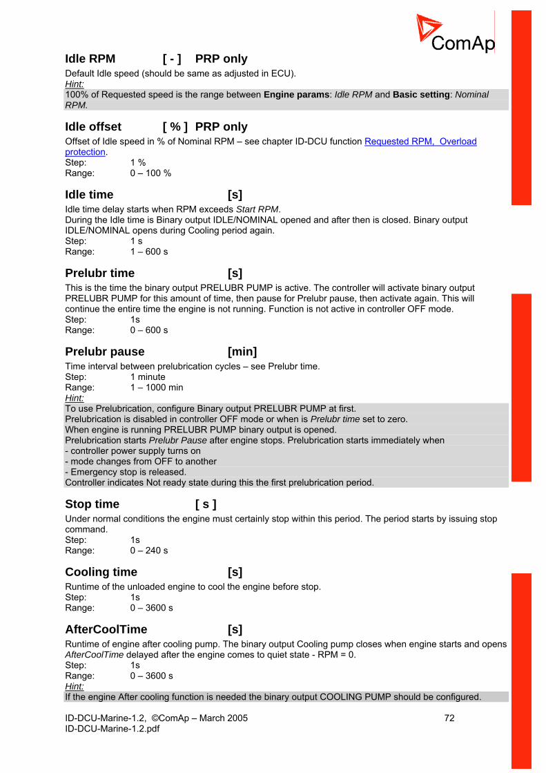
ID-DCU-Marine-1.2, ©ComAp – March 2005 72 ID-DCU-Marine-1.2.pdf
Idle RPM [ - ] PRP only Default Idle speed (should be same as adjusted in ECU). Hint: 100% of Requested speed is the range between Engine params: Idle RPM and Basic setting: Nominal RPM.
Idle offset [ % ] PRP only Offset of Idle speed in % of Nominal RPM – see chapter ID-DCU function Requested RPM, Overload protection. Step: 1 % Range: 0 – 100 %
Idle time [s] Idle time delay starts when RPM exceeds Start RPM. During the Idle time is Binary output IDLE/NOMINAL opened and after then is closed. Binary output IDLE/NOMINAL opens during Cooling period again. Step: 1 s Range: 1 – 600 s
Prelubr time [s] This is the time the binary output PRELUBR PUMP is active. The controller will activate binary output PRELUBR PUMP for this amount of time, then pause for Prelubr pause, then activate again. This will continue the entire time the engine is not running. Function is not active in controller OFF mode. Step: 1s Range: 0 – 600 s
Prelubr pause [min] Time interval between prelubrication cycles – see Prelubr time. Step: 1 minute Range: 1 – 1000 min Hint: To use Prelubrication, configure Binary output PRELUBR PUMP at first. Prelubrication is disabled in controller OFF mode or when is Prelubr time set to zero. When engine is running PRELUBR PUMP binary output is opened. Prelubrication starts Prelubr Pause after engine stops. Prelubrication starts immediately when - controller power supply turns on - mode changes from OFF to another - Emergency stop is released. Controller indicates Not ready state during this the first prelubrication period.
Stop time [ s ] Under normal conditions the engine must certainly stop within this period. The period starts by issuing stop command. Step: 1s Range: 0 – 240 s
Cooling time [s] Runtime of the unloaded engine to cool the engine before stop. Step: 1s Range: 0 – 3600 s
AfterCoolTime [s] Runtime of engine after cooling pump. The binary output Cooling pump closes when engine starts and opens AfterCoolTime delayed after the engine comes to quiet state - RPM = 0. Step: 1s Range: 0 – 3600 s Hint: If the engine After cooling function is needed the binary output COOLING PUMP should be configured.
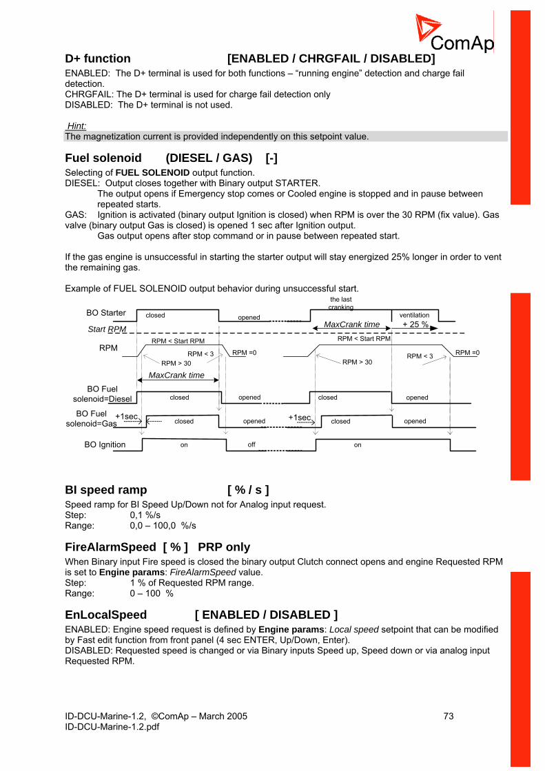
ID-DCU-Marine-1.2, ©ComAp – March 2005 73 ID-DCU-Marine-1.2.pdf
D+ function [ENABLED / CHRGFAIL / DISABLED] ENABLED: The D+ terminal is used for both functions – “running engine” detection and charge fail detection. CHRGFAIL: The D+ terminal is used for charge fail detection only DISABLED: The D+ terminal is not used. Hint: The magnetization current is provided independently on this setpoint value.
Fuel solenoid (DIESEL / GAS) [-] Selecting of FUEL SOLENOID output function. DIESEL: Output closes together with Binary output STARTER.
The output opens if Emergency stop comes or Cooled engine is stopped and in pause between repeated starts.
GAS: Ignition is activated (binary output Ignition is closed) when RPM is over the 30 RPM (fix value). Gas valve (binary output Gas is closed) is opened 1 sec after Ignition output. Gas output opens after stop command or in pause between repeated start. If the gas engine is unsuccessful in starting the starter output will stay energized 25% longer in order to vent the remaining gas. Example of FUEL SOLENOID output behavior during unsuccessful start.
Start RPM
BO Starter
RPM
BO Ignition
RPM < Start RPM
MaxCrank time
closed
on
opened
off
RPM > 30RPM < 3 RPM =0
the lastcranking
RPM > 30RPM =0
MaxCrank time + 25 %
on
RPM < Start RPM
RPM < 3
closed opened closed opened
BO Fuelsolenoid=Diesel closed opened closed opened
ventilation
BO Fuelsolenoid=Gas
+1sec +1sec
BI speed ramp [ % / s ] Speed ramp for BI Speed Up/Down not for Analog input request. Step: 0,1 %/s Range: 0,0 – 100,0 %/s
FireAlarmSpeed [ % ] PRP only When Binary input Fire speed is closed the binary output Clutch connect opens and engine Requested RPM is set to Engine params: FireAlarmSpeed value. Step: 1 % of Requested RPM range. Range: 0 – 100 %
EnLocalSpeed [ ENABLED / DISABLED ] ENABLED: Engine speed request is defined by Engine params: Local speed setpoint that can be modified by Fast edit function from front panel (4 sec ENTER, Up/Down, Enter). DISABLED: Requested speed is changed or via Binary inputs Speed up, Speed down or via analog input Requested RPM.

ID-DCU-Marine-1.2, ©ComAp – March 2005 74 ID-DCU-Marine-1.2.pdf
Local speed [ % ] Setpoint specifies engine Speed request when Engine params: EnLocalSpeed = ENABLED. Setpoint can be changed as standard setpoint or by Fast edit function: press Enter for 4 sec, Up/Down set value, press Enter to confirm. Step: 1 % Range: 0 – 100 %
Engine protect
Horn timeout [s] The maximum amount of time the Binary output Horn is closed (horn, buzzer will sound). If it desired to have the horn sound until the alarm is cleared then set to zero. Step: 1s Range: 0 – 600 s
RunOnlyBlkDel1 [s] Delay for Engine running Alarms activation – group 1 – see drawing below. Step: 1s Range: 0 – 60 s
RunOnlyBlkDel2 [s] Delay for Engine running Alarms activation – group 2. Step: 1s Range: 0 – 60 s
RunOnlyBlkDel3 [s] Delay for Engine running Alarms activation – group 3. Step: 1s Range: 0 – 60 s
BINARY INPUT
BinInp delayphysical
BINARY INPUT
closed
Internal value
Engine running state
RunOnlyBlkDel
PROTECTION activeinactive
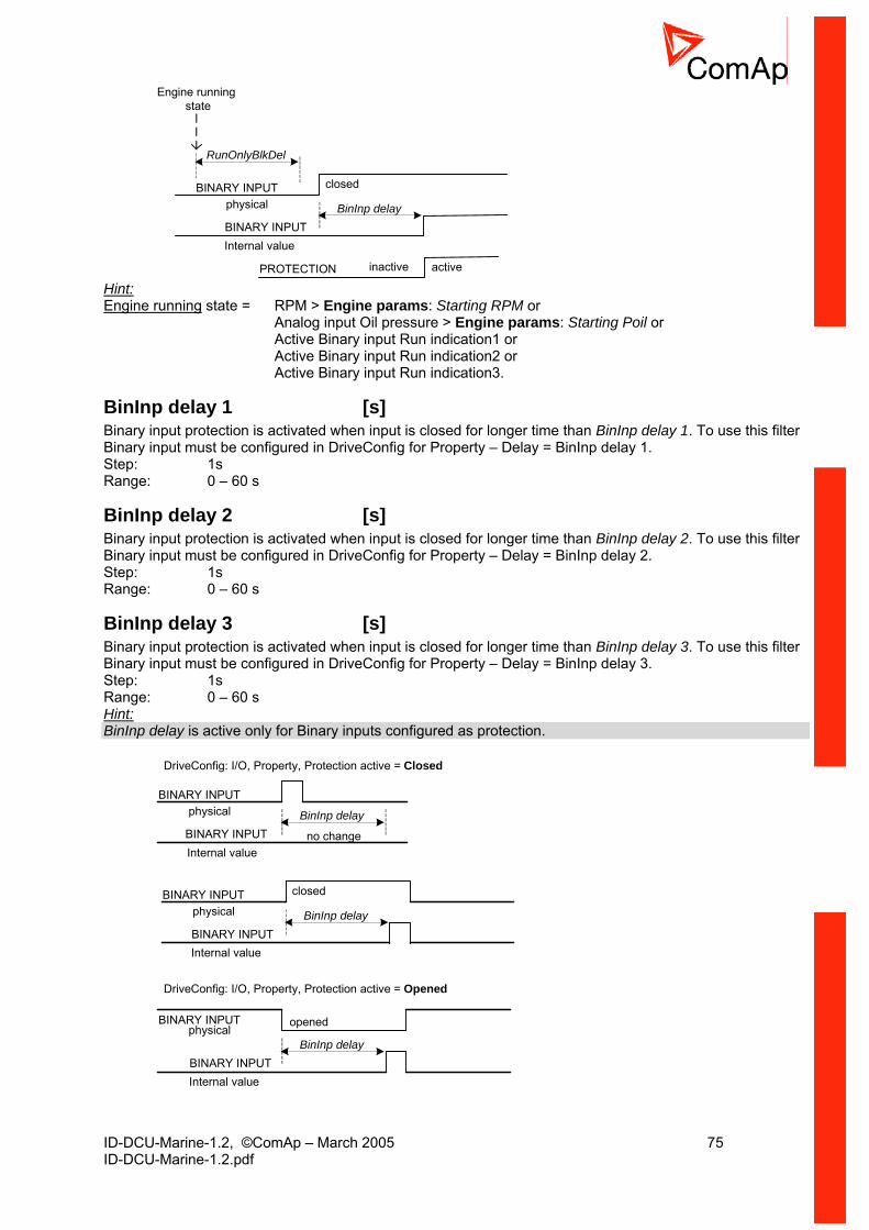
ID-DCU-Marine-1.2, ©ComAp – March 2005 75 ID-DCU-Marine-1.2.pdf
BINARY INPUT
BinInp delayphysical
BINARY INPUT
closed
Internal value
Engine running state
RunOnlyBlkDel
PROTECTION activeinactive Hint: Engine running state = RPM > Engine params: Starting RPM or Analog input Oil pressure > Engine params: Starting Poil or Active Binary input Run indication1 or Active Binary input Run indication2 or Active Binary input Run indication3.
BinInp delay 1 [s] Binary input protection is activated when input is closed for longer time than BinInp delay 1. To use this filter Binary input must be configured in DriveConfig for Property – Delay = BinInp delay 1. Step: 1s Range: 0 – 60 s
BinInp delay 2 [s] Binary input protection is activated when input is closed for longer time than BinInp delay 2. To use this filter Binary input must be configured in DriveConfig for Property – Delay = BinInp delay 2. Step: 1s Range: 0 – 60 s
BinInp delay 3 [s] Binary input protection is activated when input is closed for longer time than BinInp delay 3. To use this filter Binary input must be configured in DriveConfig for Property – Delay = BinInp delay 3. Step: 1s Range: 0 – 60 s Hint: BinInp delay is active only for Binary inputs configured as protection.
DriveConfig: I/O, Property, Protection active = Closed
BINARY INPUT
BinInp delayphysical
BINARY INPUTInternal value
no change
BINARY INPUT
BinInp delayphysical
BINARY INPUT
closed
Internal value
BINARY INPUT
BinInp delayphysical
BINARY INPUTInternal value
DriveConfig: I/O, Property, Protection active = Opened
opened
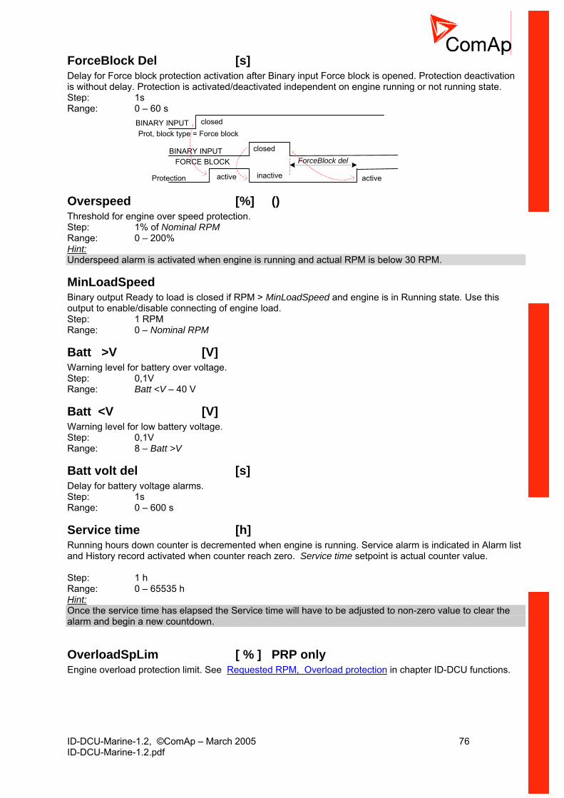
ID-DCU-Marine-1.2, ©ComAp – March 2005 76 ID-DCU-Marine-1.2.pdf
ForceBlock Del [s] Delay for Force block protection activation after Binary input Force block is opened. Protection deactivation is without delay. Protection is activated/deactivated independent on engine running or not running state. Step: 1s Range: 0 – 60 s
BINARY INPUTForceBlock delFORCE BLOCK
Protection
closed
BINARY INPUTProt, block type = Force block
closed
active activeinactive
Overspeed [%] () Threshold for engine over speed protection. Step: 1% of Nominal RPM Range: 0 – 200% Hint:Underspeed alarm is activated when engine is running and actual RPM is below 30 RPM.
MinLoadSpeed Binary output Ready to load is closed if RPM > MinLoadSpeed and engine is in Running state. Use this output to enable/disable connecting of engine load. Step: 1 RPM Range: 0 – Nominal RPM
Batt >V [V] Warning level for battery over voltage. Step: 0,1V Range: Batt <V – 40 V
Batt <V [V] Warning level for low battery voltage. Step: 0,1V Range: 8 – Batt >V
Batt volt del [s] Delay for battery voltage alarms. Step: 1s Range: 0 – 600 s
Service time [h] Running hours down counter is decremented when engine is running. Service alarm is indicated in Alarm list and History record activated when counter reach zero. Service time setpoint is actual counter value.
Step: 1 h Range: 0 – 65535 h Hint: Once the service time has elapsed the Service time will have to be adjusted to non-zero value to clear the alarm and begin a new countdown.
OverloadSpLim [ % ] PRP only Engine overload protection limit. See Requested RPM, Overload protection in chapter ID-DCU functions.
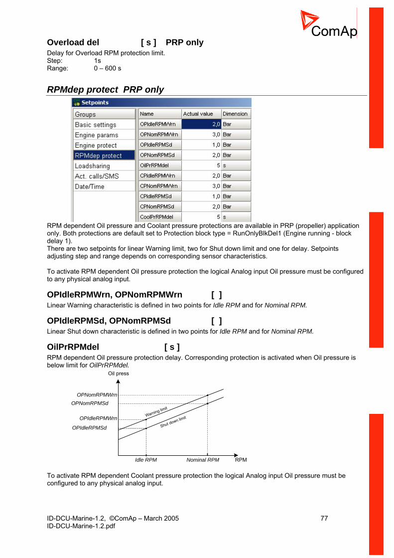
ID-DCU-Marine-1.2, ©ComAp – March 2005 77 ID-DCU-Marine-1.2.pdf
Overload del [ s ] PRP only Delay for Overload RPM protection limit. Step: 1s Range: 0 – 600 s
RPMdep protect PRP only
RPM dependent Oil pressure and Coolant pressure protections are available in PRP (propeller) application only. Both protections are default set to Protection block type = RunOnlyBlkDel1 (Engine running - block delay 1). There are two setpoints for linear Warning limit, two for Shut down limit and one for delay. Setpoints adjusting step and range depends on corresponding sensor characteristics. To activate RPM dependent Oil pressure protection the logical Analog input Oil pressure must be configured to any physical analog input.
OPIdleRPMWrn, OPNomRPMWrn [ ] Linear Warning characteristic is defined in two points for Idle RPM and for Nominal RPM.
OPIdleRPMSd, OPNomRPMSd [ ] Linear Shut down characteristic is defined in two points for Idle RPM and for Nominal RPM.
OilPrRPMdel [ s ] RPM dependent Oil pressure protection delay. Corresponding protection is activated when Oil pressure is below limit for OilPrRPMdel.
Oil press
Nominal RPMIdle RPM
Warning limit
RPM
OPIdleRPMWrnShut down limit
OPNomRPMWrn
OPIdleRPMSd
OPNomRPMSd
To activate RPM dependent Coolant pressure protection the logical Analog input Oil pressure must be configured to any physical analog input.

ID-DCU-Marine-1.2, ©ComAp – March 2005 78 ID-DCU-Marine-1.2.pdf
CPIdleRPMWrn, CPNomRPMWrn [ ] Linear Warning characteristic is defined in two points for Idle RPM and for Nominal RPM.
CPIdleRPMSd, CPNomRPMSd [ ] Linear Shut down characteristic is defined in two points for Idle RPM and for Nominal RPM.
CoolPrRPMdel [ s ] RPM dependent Coolant pressure protection delay. Corresponding protection is activated when Coolant pressure is below limit for CoolPrRPMdel.
Coolant press
Nominal RPMIdle RPM
Warning limit
RPM
CPIdleRPMWrnShut down limit
CPNomRPMWrn
CPIdleRPMSd
CPNomRPMSd
Hint: RPM dependent protections are fix configured Protection block type = Engine running only with RunOnlyBlkDel1 delay.
Load sharing PRP only
Load gain [ % ] Relative Gain of the load-sharing loop. Step: 0,1 % Range: 0,0 – 200,0 %
Load int [ % ] Relative Integration factor of the load-sharing loop. Step: 0,1 % Range: 0,0 – 100,0 %
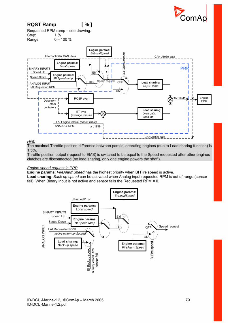
ID-DCU-Marine-1.2, ©ComAp – March 2005 79 ID-DCU-Marine-1.2.pdf
RQST Ramp [ % ] Requested RPM ramp – see drawing. Step: 1 % Range: 0 – 100 %
Speed Up
Speed Down
LAI Requested RPM
Speed request
Engine params:BI Speed ramp
RQSP aver
ET aver(average torque)
LAI Engine torque or J1939
Load sharing:RQSP ramp
BO C
lutc
h co
nnec
t
OFF
ON
Load sharing:Load gain,Load int
(actual value)
ThrottlePos
PRP
EngineECU
CAN J1939 data
Data from other
controlers
Intercontroller CAN data
CAN J1939 data
BINARY INPUTS
ANALOG INPUT
ANALOG INPUT
Engine params:Local speed
Engine params:EnLocalSpeed
EN
DIS
Hint: The maximal Throttle position difference between parallel operating engines (due to Load sharing function) is 1,5%. Throttle position output (request to EMS) is switched to be equal to the Speed requested after other engines clutches are disconnected (no load sharing, only one engine powers the shaft). Engine speed request in PRP Engine params: FireAlarmSpeed has the highest priority when BI Fire speed is active. Load sharing: Back up speed can be activated when Analog input requested RPM is out of range (sensor fail). When Binary input is not active and sensor fails the Requested RPM = 0.
Speed Up
Speed Down
LAI Requested RPMSpeed request
Engine params:BI Speed ramp
„Fast edit“ or
BINARY INPUTS
ANAL
OG
INPU
T
Engine params:Local speed
Engine params:EnLocalSpeed
EN
DIS
active when configured
BI F
ire s
peed
OFF
ONLoad sharing:Back up speed Engine params:
FireAlarmSpeed
BI B
acku
p sp
eed
& R
eque
sted
RPM
sens
or fa
il
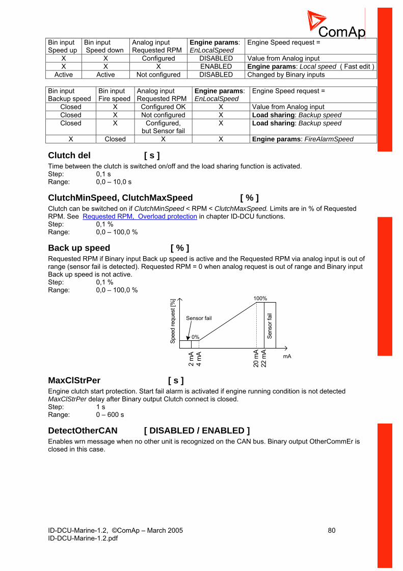
ID-DCU-Marine-1.2, ©ComAp – March 2005 80 ID-DCU-Marine-1.2.pdf
Bin input Speed up
Bin input Speed down
Analog input Requested RPM
Engine params: EnLocalSpeed
Engine Speed request =
X X Configured DISABLED Value from Analog input X X X ENABLED Engine params: Local speed ( Fast edit )
Active Active Not configured DISABLED Changed by Binary inputs Bin input Backup speed
Bin input Fire speed
Analog input Requested RPM
Engine params: EnLocalSpeed
Engine Speed request =
Closed X Configured OK X Value from Analog input Closed X Not configured X Load sharing: Backup speed Closed X Configured,
but Sensor fail X Load sharing: Backup speed
X Closed X X Engine params: FireAlarmSpeed
Clutch del [ s ] Time between the clutch is switched on/off and the load sharing function is activated. Step: 0,1 s Range: 0,0 – 10,0 s
ClutchMinSpeed, ClutchMaxSpeed [ % ] Clutch can be switched on if ClutchMinSpeed < RPM < ClutchMaxSpeed. Limits are in % of Requested RPM. See Requested RPM, Overload protection in chapter ID-DCU functions. Step: 0,1 % Range: 0,0 – 100,0 %
Back up speed [ % ] Requested RPM if Binary input Back up speed is active and the Requested RPM via analog input is out of range (sensor fail is detected). Requested RPM = 0 when analog request is out of range and Binary input Back up speed is not active. Step: 0,1 % Range: 0,0 – 100,0 %
4 m
A
20 m
A
100%
0%
mA
2 m
A
22 m
ASe
nsor
fail
Sensor fail
Spee
d re
ques
t [%
]
MaxClStrPer [ s ] Engine clutch start protection. Start fail alarm is activated if engine running condition is not detected MaxClStrPer delay after Binary output Clutch connect is closed. Step: 1 s Range: 0 – 600 s
DetectOtherCAN [ DISABLED / ENABLED ] Enables wrn message when no other unit is recognized on the CAN bus. Binary output OtherCommEr is closed in this case.
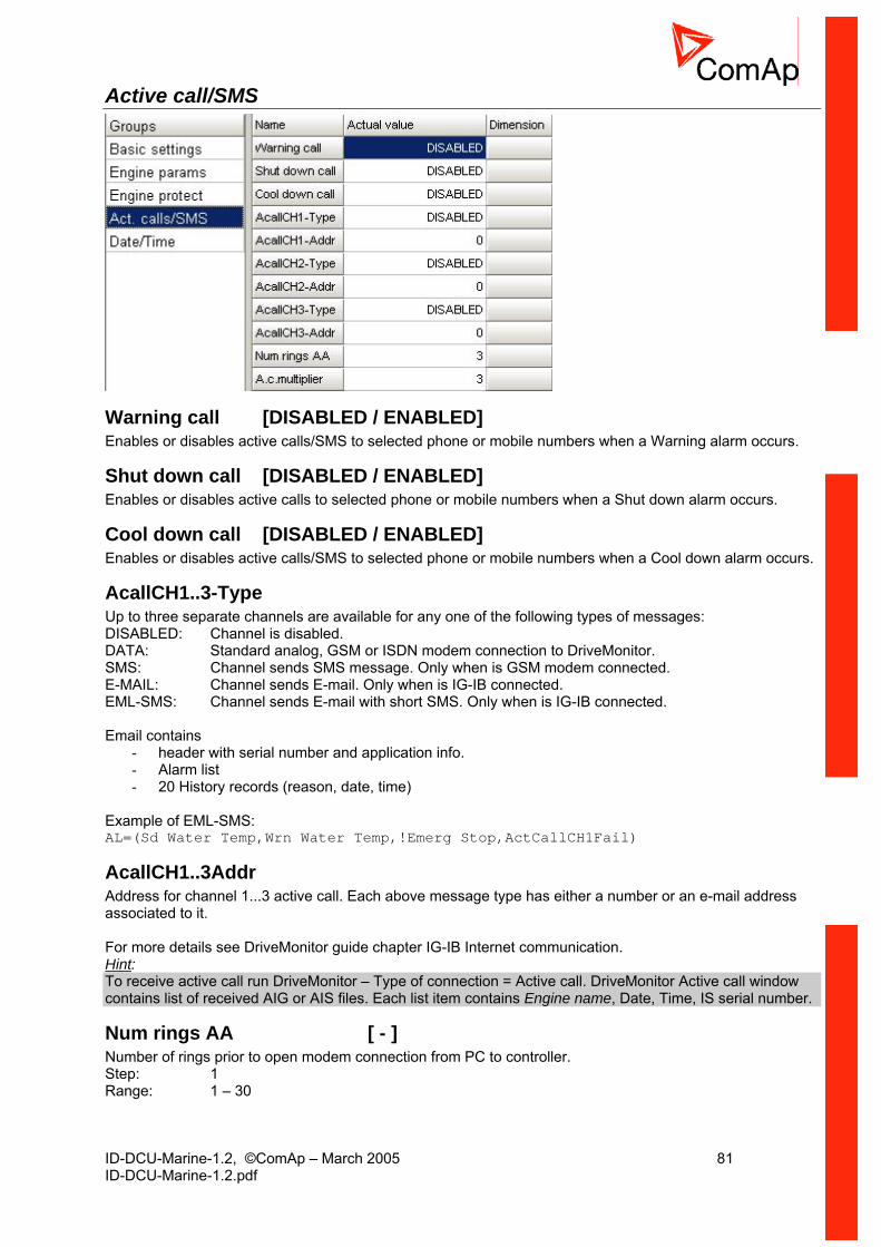
ID-DCU-Marine-1.2, ©ComAp – March 2005 81 ID-DCU-Marine-1.2.pdf
Active call/SMS
Warning call [DISABLED / ENABLED] Enables or disables active calls/SMS to selected phone or mobile numbers when a Warning alarm occurs.
Shut down call [DISABLED / ENABLED] Enables or disables active calls to selected phone or mobile numbers when a Shut down alarm occurs.
Cool down call [DISABLED / ENABLED] Enables or disables active calls/SMS to selected phone or mobile numbers when a Cool down alarm occurs.
AcallCH1..3-Type Up to three separate channels are available for any one of the following types of messages: DISABLED: Channel is disabled. DATA: Standard analog, GSM or ISDN modem connection to DriveMonitor. SMS: Channel sends SMS message. Only when is GSM modem connected. E-MAIL: Channel sends E-mail. Only when is IG-IB connected. EML-SMS: Channel sends E-mail with short SMS. Only when is IG-IB connected. Email contains
- header with serial number and application info. - Alarm list - 20 History records (reason, date, time)
Example of EML-SMS: AL=(Sd Water Temp,Wrn Water Temp,!Emerg Stop,ActCallCH1Fail)
AcallCH1..3Addr Address for channel 1...3 active call. Each above message type has either a number or an e-mail address associated to it. For more details see DriveMonitor guide chapter IG-IB Internet communication. Hint: To receive active call run DriveMonitor – Type of connection = Active call. DriveMonitor Active call window contains list of received AIG or AIS files. Each list item contains Engine name, Date, Time, IS serial number.
Num rings AA [ - ] Number of rings prior to open modem connection from PC to controller. Step: 1 Range: 1 – 30

ID-DCU-Marine-1.2, ©ComAp – March 2005 82 ID-DCU-Marine-1.2.pdf
Hint: NumberRings AA change is not accepted immediately but after controller is switched on or when modem is connected to controller.
A.c.multiplier [ - ] Setpoint specify the number of attempt to open the Active call connection when the phone line is engaged. Step: 1 Range: 1 to 250 Hint: Timeout for connection is 90 sec and after 120 sec controller starts the next attempt. Incoming calls are blocked during the time the controller is trying to send an active call type.
Date and time
Time [HHMMSS] Controller internal Real Time Clock adjustment.
Date [DDMMYY] Actual date adjustment
Time stamp per Time interval for history record. Time base is based on number of minutes since midnight. Step: 1 min Range: 0 - 240 min Hint: No history Time stamp is recorded when TimeStamp Per = 0. RTC and Date is in each History record.
Protections Protection group contains all Analog inputs and Binary inputs protection limits and delays. List is dynamically created during configuration process.

ID-DCU-Marine-1.2, ©ComAp – March 2005 83 ID-DCU-Marine-1.2.pdf
Operator Interface
Pushbuttons and LEDs
1 4
8
9
7
6
5 2 3
12
11
13
14
10
Pushbuttons and LED’s: 1. MODE→ Cycle forward through engine operation modes OFF -> MAN -> REM. 2. ←MODE Cycle backward through engine operation modes OFF -> MAN -> REM. 3. HORN RESET Deactivates the HORN. 4. FAULT RESET Acknowledges faults and alarms. 5. START Starts the engine in AUX, EME, CMB, PRP mode. 6. STOP Stops the engine in AUX, EME, CMB, PRP mode (hold time =1 sec). 7. GREEN = Engine OK. 8. RED = Engine fail. 9. GREEN = On/Off output is active. 10. On/Off button for Close load or Clutch Binary output control. 11. PAGE Cycles through the display screens MEASUREMENT->ADJUSTEMENT->HISTORY. 12. ↑ Select the set point, select the screen or increase set point value. 13. ↓ Select the set point, select the screen or decrease set point value. 14. ENTER Confirm set point value.
How to select engine mode ? Use MODE→ or ←MODE to select requested engine operation mode.
ID-DCU-Marine-1.2, ©ComAp – March 2005 84 ID-DCU-Marine-1.2.pdf
Display menus There are 4 display menus available: MEASUREMENT, External measurement, ADJUSTMENT and HISTORY. Each menu consists of several screens. Pressing the PAGE button repeatedly will scroll the user through the menu screens.
How to view measured data? Pressing the PAGE button repeatedly will scroll the user through the menu screens. Select the MEASUREMENT screen. Use ↑ and ↓ to select the screen with requested data.
How to view and edit set points? 1. Pressing the PAGE button repeatedly will scroll the user through the menu screens. Select the
ADJUSTMENT screen. 2. Use ↑ or ↓ to select requested set points group. 3. Press ENTER to confirm. 4. Use ↑ or ↓ to select requested set point. 5. Set points marked “*” are password protected. 6. Press ENTER to edit. 7. Use ↑ or ↓ to modify the set point. When ↑ or ↓ is pressed for 2 sec, auto repeat function is
activated. 8. Press ENTER to confirm or PAGE to leave without change.
Press PAGE to leave selected set points group.
How to view the HISTORY menu? 1. Pressing the PAGE button repeatedly will scroll the user through the menu screens. Select the
HISTORY screen. 2. Use ↑ or ↓ to select a requested record. 3. Use ENTER to select requested screen (record items) within displayed records
How to change the display contrast ? Press ENTER and ↑ or ↓ at the same time to adjust the best display contrast. Hint: Only in MEASUREMENT menu.
How to check the serial number and software revision? Hold down the ENTER and the press PAGE. On the display you can see Controller INFO screen for 10 seconds: Controller name (see Basic setting group) Controller serial number (8 character number) SW version: the first is the firmware version number, the second is configuration table number. Application: ID Branch: InteliDrive Hint: Only in MEASUREMENT screen.
How to change the display backlight intensity ? Press ENTER and ↑ or ↓ at the same time to adjust the best display backlight. Hint: Only in INFO screen.
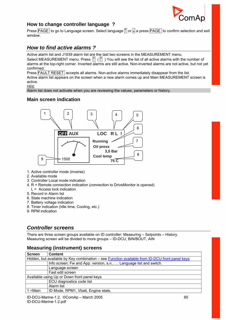
ID-DCU-Marine-1.2, ©ComAp – March 2005 85 ID-DCU-Marine-1.2.pdf
How to change controller language ? Press PAGE to go to Language screen. Select language ↑ or ↓ a press PAGE to confirm selection and exit window.
How to find active alarms ? Active alarm list and J1939 alarm list are the last two screens in the MEASUREMENT menu. Select MEASUREMENT menu. Press ↑ ( ↑ ) You will see the list of all active alarms with the number of alarms at the top-right corner. Inverted alarms are still active. Non-inverted alarms are not active, but not yet confirmed. Press FAULT RESET accepts all alarms. Non-active alarms immediately disappear from the list. Active alarm list appears on the screen when a new alarm comes up and Main MEASUREMENT screen is active. Hint: Alarm list does not activate when you are reviewing the values, parameters or history.
Main screen indication
OFF AUX LOC R L !RunningOil press 3,5 BarCool temp
75 C1500
1 2 4
7
6
53
8
9
1. Active controller mode (inverse) 2. Available mode 3. Controller Local mode indication 4. R = Remote connection indication (connection to DriveMonitor is opened) L = Access lock indication 5. Record in Alarm list 6. State machine indication 7. Battery voltage indication 8. Timer indication (Idle time, Cooling, etc.) 9. RPM indication
Controller screens There are three screen groups available on ID controller: Measuring – Setpoints – History. Measuring screen will be divided to more groups – ID-DCU, BIN/BOUT, AIN
Measuring (instrument) screens Screen Content Hidden, but available by Key combination – see Function available from ID-DCU front panel keys Info screen: Fw and App. version, s.n., … Language list and switch. Language screen Fast edit screen Available using Up or Down front panel keys ECU diagnostics code list Alarm list 1 =Main ID Mode, RPM1, Vbatt, Engine state,

ID-DCU-Marine-1.2, ©ComAp – March 2005 86 ID-DCU-Marine-1.2.pdf
screen Indication: Local, Alarm (in AL or ECU list), Remote data connection active, Access Lock 2 Analog 1 to Analog 4 , 4x single barograph 3 Analog 5 to Analog 8 , 4x single barograph 4 Battery ID-DCU, barograph ??? 5 ID-DCU BI 1 to 7 6 ID-DCU BI 8 to 14 7 ID-DCU BO 1 to 7 8 ID-DCU BO 8 to 14 9 Statistics: Run hours, Number of starts, Service time Following screens appears depend on configuration Opt ID RPU: 6x BI, BW indication is negative Opt ID-RPU: 4x BO, BW indication is negative + RPU status Opt ID-RPU: Battery A, B, status, RPM2 Opt Analog 1 to Analog 8, Name- value dimension, active alarm is negative (1x IS-AIN8) Opt IS-BIN BI indication 1 to 8 Opt IS-BIN BI indication 9 to 16 Opt IS-BIN BO indication 1 to 8 Opt ECU values I. Opt ECU values II. Setpoints screens correspond with Setpoint table above.
Alarm indication Possible Alarm list and History record prefixes
Prefix Meaning Wrn Warning Sd Shutdown Cd Cooldown Bw Broken wire Fls Sensor fail
Three state Alarm list indication * Wrn Water temp Active not accepted alarm Wrn Water temp Active not accepted alarm * Wrn Water temp Inactive not accepted alarm Inactive accepted alarm
ECU Alarm list - SPN/FMI codes screen E n g O i l P r e s s W R N B o o s t P r e s s F L S E n g O i l T e m p F L S 6 2 9 F L S > C o n t r o l l e r # 1 E n g C o o l T e m p W R N F C : 1 1 0 O C : 7 F M I : 3
Info screen Info Comment CBH InteliDrive Product type ComAp 2003 – 2004 Company name
ID-DCU-Marine
Controller name
Serial: 0200FFFF Controller serial number Sw ver: 1.0 Software version Appl: PRP Application Branch: DCU Marine Customer branch
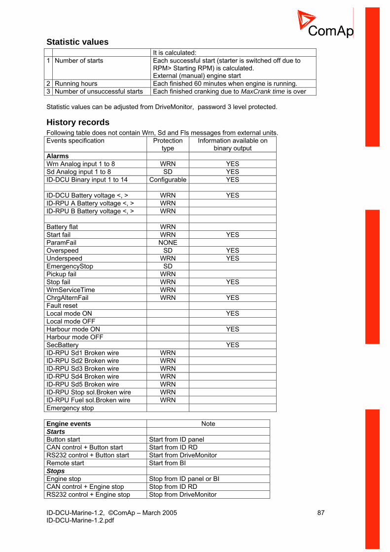
ID-DCU-Marine-1.2, ©ComAp – March 2005 87 ID-DCU-Marine-1.2.pdf
Statistic values It is calculated: 1 Number of starts Each successful start (starter is switched off due to
RPM> Starting RPM) is calculated. External (manual) engine start
2 Running hours Each finished 60 minutes when engine is running. 3 Number of unsuccessful starts Each finished cranking due to MaxCrank time is over Statistic values can be adjusted from DriveMonitor, password 3 level protected.
History records Following table does not contain Wrn, Sd and Fls messages from external units. Events specification Protection
type Information available on
binary output Alarms Wrn Analog input 1 to 8 WRN YES Sd Analog input 1 to 8 SD YES ID-DCU Binary input 1 to 14 Configurable YES ID-DCU Battery voltage <, > WRN YES ID-RPU A Battery voltage <, > WRN ID-RPU B Battery voltage <, > WRN Battery flat WRN Start fail WRN YES ParamFail NONE Overspeed SD YES Underspeed WRN YES EmergencyStop SD Pickup fail WRN Stop fail WRN YES WrnServiceTime WRN ChrgAlternFail WRN YES Fault reset Local mode ON YES Local mode OFF Harbour mode ON YES Harbour mode OFF SecBattery YES ID-RPU Sd1 Broken wire WRN ID-RPU Sd2 Broken wire WRN ID-RPU Sd3 Broken wire WRN ID-RPU Sd4 Broken wire WRN ID-RPU Sd5 Broken wire WRN ID-RPU Stop sol.Broken wire WRN ID-RPU Fuel sol.Broken wire WRN Emergency stop Engine events Note Starts Button start Start from ID panel CAN control + Button start Start from ID RD RS232 control + Button start Start from DriveMonitor Remote start Start from BI Stops Engine stop Stop from ID panel or BI CAN control + Engine stop Stop from ID RD RS232 control + Engine stop Stop from DriveMonitor
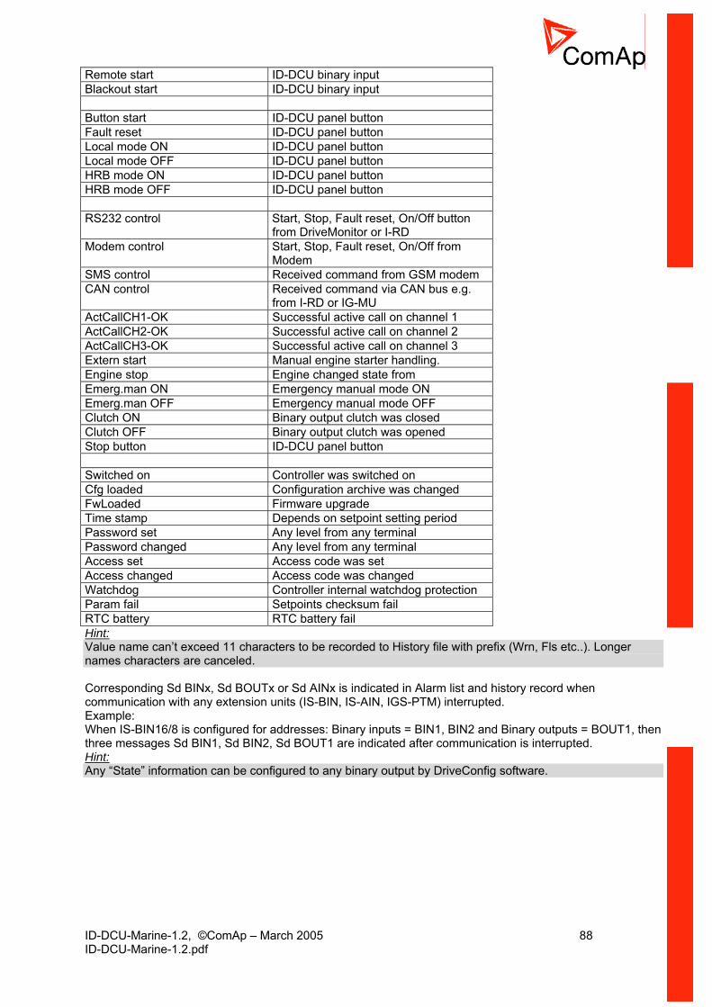
ID-DCU-Marine-1.2, ©ComAp – March 2005 88 ID-DCU-Marine-1.2.pdf
Remote start ID-DCU binary input Blackout start ID-DCU binary input Button start ID-DCU panel button Fault reset ID-DCU panel button Local mode ON ID-DCU panel button Local mode OFF ID-DCU panel button HRB mode ON ID-DCU panel button HRB mode OFF ID-DCU panel button RS232 control Start, Stop, Fault reset, On/Off button
from DriveMonitor or I-RD Modem control Start, Stop, Fault reset, On/Off from
Modem SMS control Received command from GSM modem CAN control Received command via CAN bus e.g.
from I-RD or IG-MU ActCallCH1-OK Successful active call on channel 1 ActCallCH2-OK Successful active call on channel 2 ActCallCH3-OK Successful active call on channel 3 Extern start Manual engine starter handling. Engine stop Engine changed state from Emerg.man ON Emergency manual mode ON Emerg.man OFF Emergency manual mode OFF Clutch ON Binary output clutch was closed Clutch OFF Binary output clutch was opened Stop button ID-DCU panel button Switched on Controller was switched on Cfg loaded Configuration archive was changed FwLoaded Firmware upgrade Time stamp Depends on setpoint setting period Password set Any level from any terminal Password changed Any level from any terminal Access set Access code was set Access changed Access code was changed Watchdog Controller internal watchdog protection Param fail Setpoints checksum fail RTC battery RTC battery fail Hint: Value name can’t exceed 11 characters to be recorded to History file with prefix (Wrn, Fls etc..). Longer names characters are canceled. Corresponding Sd BINx, Sd BOUTx or Sd AINx is indicated in Alarm list and history record when communication with any extension units (IS-BIN, IS-AIN, IGS-PTM) interrupted. Example: When IS-BIN16/8 is configured for addresses: Binary inputs = BIN1, BIN2 and Binary outputs = BOUT1, then three messages Sd BIN1, Sd BIN2, Sd BOUT1 are indicated after communication is interrupted. Hint: Any “State” information can be configured to any binary output by DriveConfig software.

ID-DCU-Marine-1.2, ©ComAp – March 2005 89 ID-DCU-Marine-1.2.pdf
Functions available from ID-DCU front panel keys Function Key combination From where Contrast increase Enter - Up Contrast decrease Enter - Down Info screen Enter - Page Local mode ON Enter - Mode > (Right) Local mode OFF Enter - Mode < (Left) Fast edit Enter hold for 4 sec.
Main screen
Fault code reset Fault reset Alarm list ECU fault code reset Fault reset ECU Alarm list Requested speed increase Up Requested speed decrease Down
Request confirmation and exit
Enter active when Engine params: EnLocalSpeed = ENABLED
Exit without confirmation Page
Fast edit screen
Backlight increase Enter – Up Backlight decrease Enter - Down Go to Language screen Page
Info screen exit Automatic after 10 sec to Main screen
Info screen
Language selection Up or Down key Language screen Language screen exit Enter
Note: Enter – Up means hold Enter and press Up The system supports following character sets: West European - Code page 1252 in Windows East European - Code page 1250 in Windows Russian - Code page 1251 in Windows Turkish - Code page 1254 in Windows Simplified Chinese - Code page 936 in Windows. Hint: If the configuration table has a code page, that is not supported in the display processor, “Unsupported code page” message appears on the ID screen. Press PAGE to return back to Language selection.
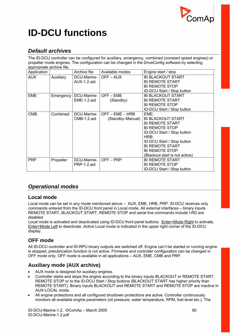
ID-DCU-Marine-1.2, ©ComAp – March 2005 90 ID-DCU-Marine-1.2.pdf
ID-DCU functions
Default archives The ID-DCU controller can be configured for auxiliary, emergency, combined (constant speed engines) or propeller mode engines. The configuration can be changed in the DriveConfig software by selecting appropriate archive file. Application Archive file Available modes Engine start / stop AUX Auxiliary DCU-Marine-
AUX-1.2.aid OFF – AUX BI BLACKOUT START
BI REMOTE START BI REMOTE STOP ID-DCU Start / Stop button
EME Emergency DCU-Marine-EME-1.2.aid
OFF – EME (Standby)
BI BLACKOUT START BI REMOTE START BI REMOTE STOP ID-DCU Start / Stop button
CMB Combined DCU-Marine-CMB-1.2.aid
OFF – EME – HRB (Standby–Manual)
EME: BI BLACKOUT START BI REMOTE START BI REMOTE STOP ID-DCU Start / Stop button HRB: ID-DCU Start / Stop button BI REMOTE START BI REMOTE STOP (Blackout start is not active)
PRP Propeller DCU-Marine-PRP-1.2.aid
OFF – PRP BI REMOTE START BI REMOTE STOP ID-DCU Start / Stop button
Operational modes
Local mode Local mode can be set in any mode mentioned above – AUX, EME, HRB, PRP. ID-DCU receives only commands entered from the ID-DCU front panel in Local mode. All external interfaces – binary inputs REMOTE START, BLACKOUT START, REMOTE STOP and serial line commands include I-RD are disabled. Local mode is activated and deactivated using ID-DCU front panel buttons: Enter+Mode Right to activate, Enter+Mode Left to deactivate. Active Local mode is indicated in the upper right corner of the ID-DCU display.
OFF mode All ID-DCU controller and ID-RPU binary outputs are switched off. Engine can’t be started or running engine is stopped, prelubrication function is not active. Firmware and controller configuration can be changed in OFF mode only. OFF mode is available in all applications – AUX, EME, CMB and PRP.
Auxiliary mode (AUX archive) • AUX mode is designed for auxiliary engines. • Controller starts and stops the engine according to the binary inputs BLACKOUT or REMOTE START,
REMOTE STOP or to the ID-DCU Start / Stop buttons (BLACKOUT START has higher priority than REMOTE START). Binary inputs BLACKOUT and REMOTE START and REMOTE STOP are inactive in AUX-LOCAL mode.
• All engine protections and all configured shutdown protections are active. Controller continuously monitors all available engine parameters (oil pressure, water temperature, RPM, fuel level etc.). The

ID-DCU-Marine-1.2, ©ComAp – March 2005 91 ID-DCU-Marine-1.2.pdf
engine will stop and activates COMMON WARNING and SHUTDOWN outputs and writes record to the history file when detects any active Shut down alarm. This condition can be signaled by Active call feature to remote operator via modem, SMS or e-mail.
Emergency mode (EME archive) • The engine is used for emergency engines. • Controller starts and stops the engine according to the binary inputs BLACKOUT or REMOTE START,
REMOTE STOP or to the ID-DCU Start / Stop buttons. Binary inputs BLACKOUT and REMOTE START and REMOTE STOP are inactive in LOCAL mode.
Start fail is only indicated but No Shut down is activated in the case of unsuccessful start and starting procedure repeats until engine successfully starts or Remote stop or Stop button is activated. • The controller still measures all engine parameters. But it only records to the history file and can notify
remote operator via Active call when detects any parameter out of range. • The only active shut down protection is engine over speed and Emergency stop.
Combined – Harbour mode (CMB archive) ID-DCU can be switched to EME or HRB mode by ID-DCU Mode panel buttons. • EME mode behavior is like above. • In HRB mode the controller operates like in AUX mode (all engine protections are active) but message
“HARBOUR MODE in Alarm list and Binary outputs HRB mode and binary output COMMON ALARM is active.
• Controller starts and stops the engine according to the binary inputs REMOTE START, REMOTE STOP or to the ID-DCU panel Start/Stop buttons. Binary input BLACKOUT START is inactive.
Propeller mode (PRP archive) • PRP mode is designed for multiple propulsion engines with variable speed • Controller starts and stops the engine according to the binary inputs REMOTE START, REMOTE STOP
or to the ID-DCU Start / Stop buttons. Binary inputs REMOTE START and REMOTE STOP are inactive -LOCAL mode.
• All engine protections and all configured shutdown protections are active. Controller continuously monitors all available engine parameters (oil pressure, water temperature, RPM, fuel level etc.). The engine will stop and activates COMMON WARNING and SHUTDOWN outputs and writes record to the history file when detects any active Shut down alarm. This condition can be signaled by Active call feature to remote operator via modem, SMS or e-mail
Other functions Controller (except OFF mode) accepts when engine is started outside controller (by hand) or when controller power supply is switched-on on already running engine.
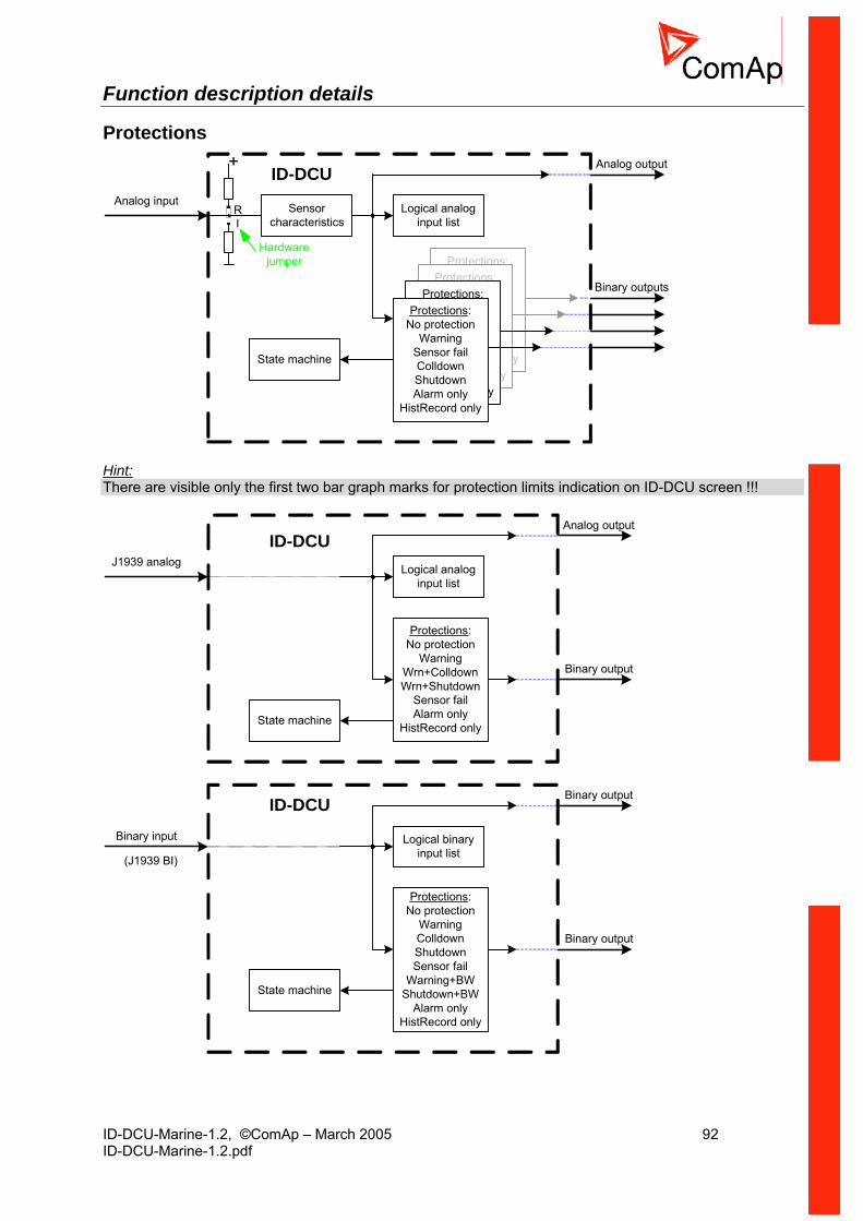
ID-DCU-Marine-1.2, ©ComAp – March 2005 92 ID-DCU-Marine-1.2.pdf
Function description details
Protections
Protections:No protection
WarningSensor failColldownShutdownAlarm only
HistRecord only
Protections:No protection
WarningSensor failColldownShutdownAlarm only
HistRecord only
Protections:No protection
WarningSensor failColldownShutdownAlarm only
HistRecord only
Sensorcharacteristics
+
RI
Analog input
Protections:No protection
WarningSensor failColldownShutdownAlarm only
HistRecord only
Logical analoginput list
Analog output
Binary outputs
State machine
Hardwarejumper
ID-DCU
Hint: There are visible only the first two bar graph marks for protection limits indication on ID-DCU screen !!!
Logical analoginput list
Analog output
Binary output
State machine
J1939 analog
Protections:No protection
WarningWrn+ColldownWrn+Shutdown
Sensor failAlarm only
HistRecord only
ID-DCU
Protections:No protection
WarningColldownShutdownSensor fail
Warning+BWShutdown+BW
Alarm onlyHistRecord only
Logical binaryinput list
Binary output
Binary output
State machine
Binary input
(J1939 BI)
ID-DCU

ID-DCU-Marine-1.2, ©ComAp – March 2005 93 ID-DCU-Marine-1.2.pdf
How to configure analog input window protection 1. Switch DriveConfig to EXPERT mode.
2. Configure standard two level analog protection
3. Add another protections in EXPERT window. There can be set the same delay for all four limits.
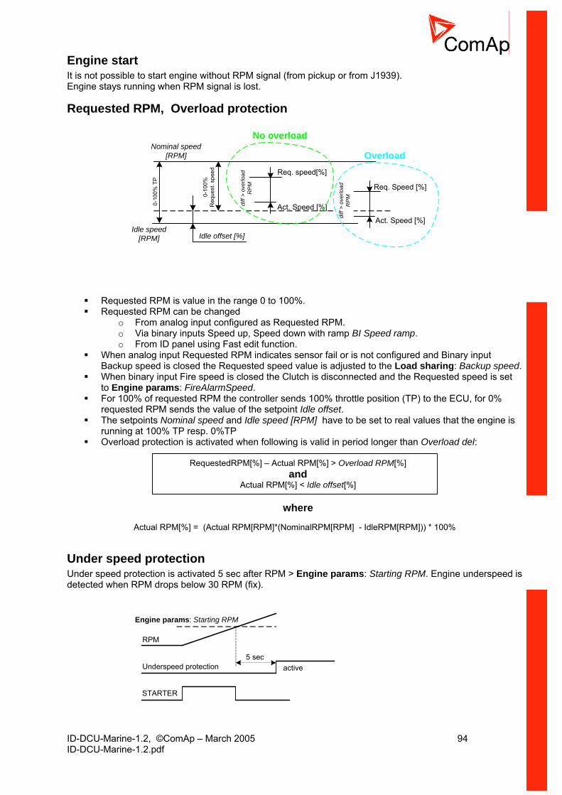
ID-DCU-Marine-1.2, ©ComAp – March 2005 94 ID-DCU-Marine-1.2.pdf
Engine start It is not possible to start engine without RPM signal (from pickup or from J1939). Engine stays running when RPM signal is lost.
Requested RPM, Overload protection
Nominal speed[RPM]
0-10
0%R
eque
st. s
peed
Idle speed[RPM]
Act. Speed [%]
Req. speed[%]
diff
> ov
erlo
adR
PM
diff
> ov
erlo
adR
PM
Req. Speed [%]
Act. Speed [%]
0-10
0% T
P
Idle offset [%]
No overload
Overload
Requested RPM is value in the range 0 to 100%. Requested RPM can be changed
o From analog input configured as Requested RPM. o Via binary inputs Speed up, Speed down with ramp BI Speed ramp. o From ID panel using Fast edit function.
When analog input Requested RPM indicates sensor fail or is not configured and Binary input Backup speed is closed the Requested speed value is adjusted to the Load sharing: Backup speed.
When binary input Fire speed is closed the Clutch is disconnected and the Requested speed is set to Engine params: FireAlarmSpeed.
For 100% of requested RPM the controller sends 100% throttle position (TP) to the ECU, for 0% requested RPM sends the value of the setpoint Idle offset.
The setpoints Nominal speed and Idle speed [RPM] have to be set to real values that the engine is running at 100% TP resp. 0%TP
Overload protection is activated when following is valid in period longer than Overload del:
RequestedRPM[%] – Actual RPM[%] > Overload RPM[%] and
Actual RPM[%] < Idle offset[%]
where Actual RPM[%] = (Actual RPM[RPM]*(NominalRPM[RPM] - IdleRPM[RPM])) * 100%
Under speed protection Under speed protection is activated 5 sec after RPM > Engine params: Starting RPM. Engine underspeed is detected when RPM drops below 30 RPM (fix).
Underspeed protection
RPM
active5 sec
STARTER
Engine params: Starting RPM

ID-DCU-Marine-1.2, ©ComAp – March 2005 95 ID-DCU-Marine-1.2.pdf
Protection delay and blocking BINARY INPUT
BinInp delayphysical
BINARY INPUT
closed
Internal value
BINARY INPUT
BinInp delayphysical
BINARY INPUTInternal value
DriveConfig: I/O, Property, Protection active = Opened
opened
BINARY INPUT
BinInp delayphysical
BINARY INPUT
closed
Internal value
Engine running state
RunOnlyBlkDel
PROTECTION activeinactive
BINARY INPUT
BinInp delayphysical
BINARY INPUT
closed
Internal value
Engine running state
RunOnlyBlkDel
PROTECTION activeinactive
Engine running state RPM > Engine params: Starting RPM or AI Oil pressure > Engine params: Starting Poil or active BI Run indication1 or active BI Run indication2 or active BI Run indication3
Universal states State is a value joined to each Analog input or value. State indicates if any protection configured on corresponding analog input is active or not.. When is any state configured as protection the corresponding Binary output appears in Analog protection list and can be used for selective external indication of Alarm. State is reset (output is opened) when corresponding Alarm is not active and confirmed (Fault reset was pressed).
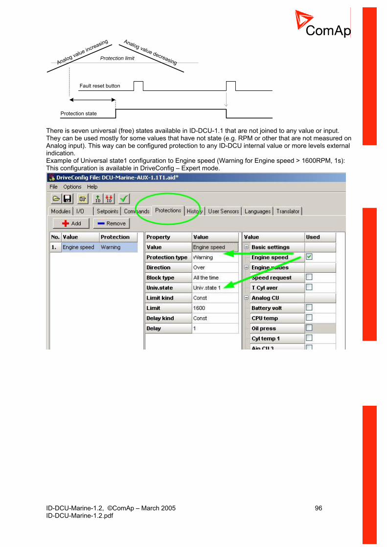
ID-DCU-Marine-1.2, ©ComAp – March 2005 96 ID-DCU-Marine-1.2.pdf
Protection limitAnalog value increasing Analog value decreasing
Fault reset button
Protection state There is seven universal (free) states available in ID-DCU-1.1 that are not joined to any value or input. They can be used mostly for some values that have not state (e.g. RPM or other that are not measured on Analog input). This way can be configured protection to any ID-DCU internal value or more levels external indication. Example of Universal state1 configuration to Engine speed (Warning for Engine speed > 1600RPM, 1s): This configuration is available in DriveConfig – Expert mode.

ID-DCU-Marine-1.2, ©ComAp – March 2005 97 ID-DCU-Marine-1.2.pdf
ID-RPU Redundancy protection unit
Binary information from ID-RPU to ID-DCU Symbol Meaning SD1 … SD5 State of all binary inputs SD1-SD5 BW1 … BW5 State of all BW protections PRIFAIL Primary A battery fail = switched to B battery ESTOP Binary input Emergency stop state BWSS Stop solenoid output BW indication BWFS Fuel solenoid output BW indication Binary information from ID-DCU to ID-RPU Symbol Meaning COMMWRN Binary output Common warning COMMSD Binary output Common shut down FUELSOL Binary output Fuel solenoid STOPSOL Binary output Stop solenoid MODE Controller application AUX – EME (or Sd override active)
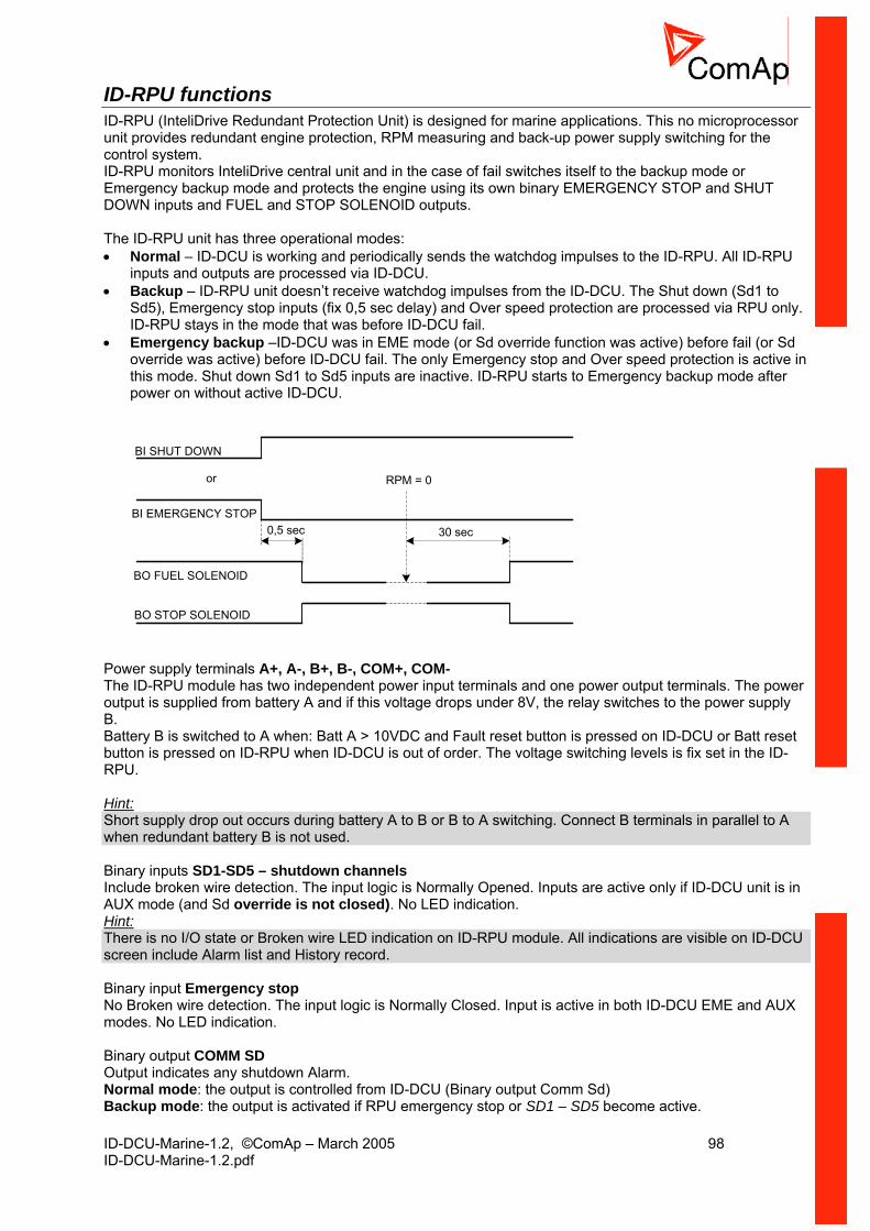
ID-DCU-Marine-1.2, ©ComAp – March 2005 98 ID-DCU-Marine-1.2.pdf
ID-RPU functions ID-RPU (InteliDrive Redundant Protection Unit) is designed for marine applications. This no microprocessor unit provides redundant engine protection, RPM measuring and back-up power supply switching for the control system. ID-RPU monitors InteliDrive central unit and in the case of fail switches itself to the backup mode or Emergency backup mode and protects the engine using its own binary EMERGENCY STOP and SHUT DOWN inputs and FUEL and STOP SOLENOID outputs. The ID-RPU unit has three operational modes: • Normal – ID-DCU is working and periodically sends the watchdog impulses to the ID-RPU. All ID-RPU
inputs and outputs are processed via ID-DCU. • Backup – ID-RPU unit doesn’t receive watchdog impulses from the ID-DCU. The Shut down (Sd1 to
Sd5), Emergency stop inputs (fix 0,5 sec delay) and Over speed protection are processed via RPU only. ID-RPU stays in the mode that was before ID-DCU fail.
• Emergency backup –ID-DCU was in EME mode (or Sd override function was active) before fail (or Sd override was active) before ID-DCU fail. The only Emergency stop and Over speed protection is active in this mode. Shut down Sd1 to Sd5 inputs are inactive. ID-RPU starts to Emergency backup mode after power on without active ID-DCU.
BI EMERGENCY STOP
BI SHUT DOWN
or
0,5 sec 30 sec
BO FUEL SOLENOID
BO STOP SOLENOID
RPM = 0
Power supply terminals A+, A-, B+, B-, COM+, COM- The ID-RPU module has two independent power input terminals and one power output terminals. The power output is supplied from battery A and if this voltage drops under 8V, the relay switches to the power supply B. Battery B is switched to A when: Batt A > 10VDC and Fault reset button is pressed on ID-DCU or Batt reset button is pressed on ID-RPU when ID-DCU is out of order. The voltage switching levels is fix set in the ID-RPU. Hint: Short supply drop out occurs during battery A to B or B to A switching. Connect B terminals in parallel to A when redundant battery B is not used. Binary inputs SD1-SD5 – shutdown channels Include broken wire detection. The input logic is Normally Opened. Inputs are active only if ID-DCU unit is in AUX mode (and Sd override is not closed). No LED indication. Hint: There is no I/O state or Broken wire LED indication on ID-RPU module. All indications are visible on ID-DCU screen include Alarm list and History record. Binary input Emergency stop No Broken wire detection. The input logic is Normally Closed. Input is active in both ID-DCU EME and AUX modes. No LED indication. Binary output COMM SD Output indicates any shutdown Alarm. Normal mode: the output is controlled from ID-DCU (Binary output Comm Sd) Backup mode: the output is activated if RPU emergency stop or SD1 – SD5 become active.
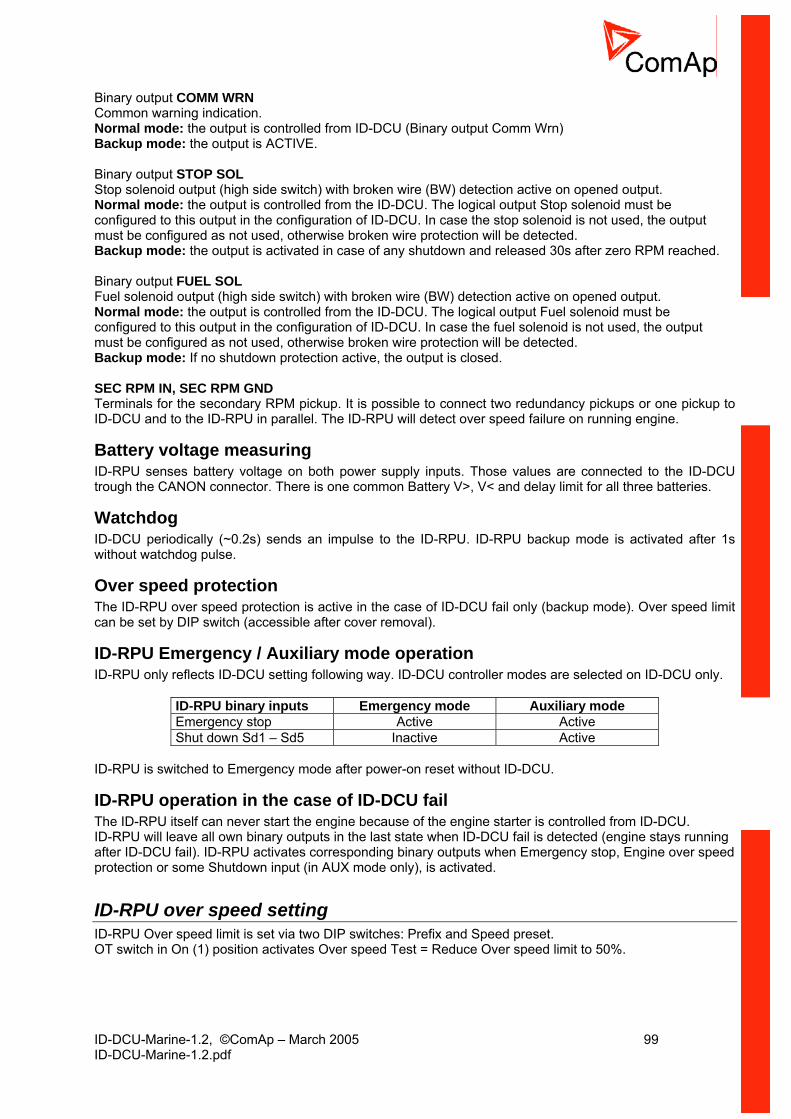
ID-DCU-Marine-1.2, ©ComAp – March 2005 99 ID-DCU-Marine-1.2.pdf
Binary output COMM WRN Common warning indication. Normal mode: the output is controlled from ID-DCU (Binary output Comm Wrn) Backup mode: the output is ACTIVE. Binary output STOP SOL Stop solenoid output (high side switch) with broken wire (BW) detection active on opened output. Normal mode: the output is controlled from the ID-DCU. The logical output Stop solenoid must be configured to this output in the configuration of ID-DCU. In case the stop solenoid is not used, the output must be configured as not used, otherwise broken wire protection will be detected. Backup mode: the output is activated in case of any shutdown and released 30s after zero RPM reached. Binary output FUEL SOL Fuel solenoid output (high side switch) with broken wire (BW) detection active on opened output. Normal mode: the output is controlled from the ID-DCU. The logical output Fuel solenoid must be configured to this output in the configuration of ID-DCU. In case the fuel solenoid is not used, the output must be configured as not used, otherwise broken wire protection will be detected. Backup mode: If no shutdown protection active, the output is closed. SEC RPM IN, SEC RPM GND Terminals for the secondary RPM pickup. It is possible to connect two redundancy pickups or one pickup to ID-DCU and to the ID-RPU in parallel. The ID-RPU will detect over speed failure on running engine.
Battery voltage measuring ID-RPU senses battery voltage on both power supply inputs. Those values are connected to the ID-DCU trough the CANON connector. There is one common Battery V>, V< and delay limit for all three batteries.
Watchdog ID-DCU periodically (~0.2s) sends an impulse to the ID-RPU. ID-RPU backup mode is activated after 1s without watchdog pulse.
Over speed protection The ID-RPU over speed protection is active in the case of ID-DCU fail only (backup mode). Over speed limit can be set by DIP switch (accessible after cover removal).
ID-RPU Emergency / Auxiliary mode operation ID-RPU only reflects ID-DCU setting following way. ID-DCU controller modes are selected on ID-DCU only.
ID-RPU binary inputs Emergency mode Auxiliary mode Emergency stop Active Active Shut down Sd1 – Sd5 Inactive Active
ID-RPU is switched to Emergency mode after power-on reset without ID-DCU.
ID-RPU operation in the case of ID-DCU fail The ID-RPU itself can never start the engine because of the engine starter is controlled from ID-DCU. ID-RPU will leave all own binary outputs in the last state when ID-DCU fail is detected (engine stays running after ID-DCU fail). ID-RPU activates corresponding binary outputs when Emergency stop, Engine over speed protection or some Shutdown input (in AUX mode only), is activated.
ID-RPU over speed setting ID-RPU Over speed limit is set via two DIP switches: Prefix and Speed preset. OT switch in On (1) position activates Over speed Test = Reduce Over speed limit to 50%.
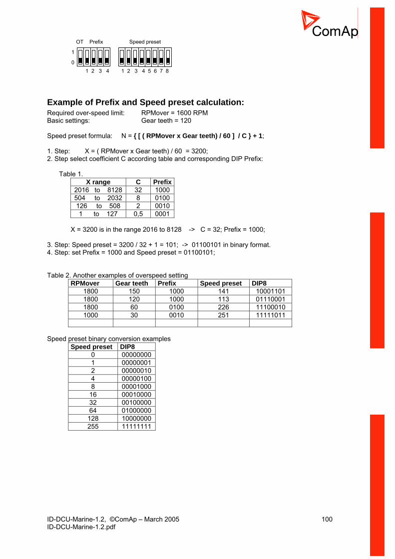
ID-DCU-Marine-1.2, ©ComAp – March 2005 100 ID-DCU-Marine-1.2.pdf
1 2 3 4 1 2 3 4 5 6 7 8
OT Prefix Speed preset
0
1
Example of Prefix and Speed preset calculation: Required over-speed limit: RPMover = 1600 RPM Basic settings: Gear teeth = 120 Speed preset formula: N = [ ( RPMover x Gear teeth) / 60 ] / C + 1; 1. Step: X = ( RPMover x Gear teeth) / 60 = 3200; 2. Step select coefficient C according table and corresponding DIP Prefix:
Table 1.
X range C Prefix2016 to 8128 32 1000 504 to 2032 8 0100 126 to 508 2 0010 1 to 127 0,5 0001
X = 3200 is in the range 2016 to 8128 -> C = 32; Prefix = 1000;
3. Step: Speed preset = 3200 / 32 + 1 = 101; -> 01100101 in binary format. 4. Step: set Prefix = 1000 and Speed preset = 01100101; Table 2. Another examples of overspeed setting
RPMover Gear teeth Prefix Speed preset DIP8 1800 150 1000 141 10001101 1800 120 1000 113 01110001 1800 60 0100 226 11100010 1000 30 0010 251 11111011
Speed preset binary conversion examples
Speed preset DIP8 0 00000000 1 00000001 2 00000010 4 00000100 8 00001000
16 00010000 32 00100000 64 01000000 128 10000000 255 11111111
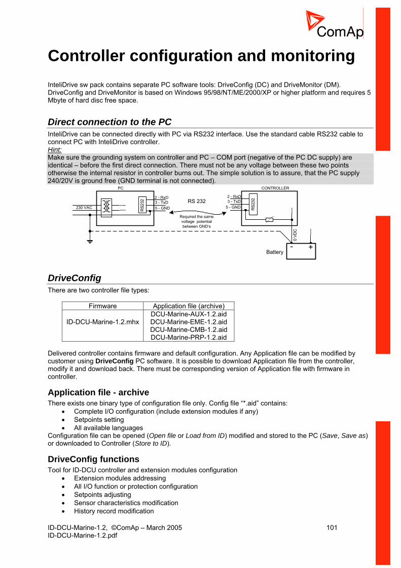
ID-DCU-Marine-1.2, ©ComAp – March 2005 101 ID-DCU-Marine-1.2.pdf
Controller configuration and monitoring InteliDrive sw pack contains separate PC software tools: DriveConfig (DC) and DriveMonitor (DM). DriveConfig and DriveMonitor is based on Windows 95/98/NT/ME/2000/XP or higher platform and requires 5 Mbyte of hard disc free space.
Direct connection to the PC InteliDrive can be connected directly with PC via RS232 interface. Use the standard cable RS232 cable to connect PC with InteliDrive controller. Hint: Make sure the grounding system on controller and PC – COM port (negative of the PC DC supply) are identical – before the first direct connection. There must not be any voltage between these two points otherwise the internal resistor in controller burns out. The simple solution is to assure, that the PC supply 240/20V is ground free (GND terminal is not connected).
5 - GND
2 - RxD3 - TxD
PC
5 - GND
2 - RxD3 - TxD
RS2
32
RS2
32
230 VAC
0 VD
C
CONTROLLER
+-Battery
Required the samevoltage potentialbetween GND‘s
RS 232
DriveConfig There are two controller file types:
Firmware Application file (archive)
ID-DCU-Marine-1.2.mhx DCU-Marine-AUX-1.2.aid DCU-Marine-EME-1.2.aid DCU-Marine-CMB-1.2.aid DCU-Marine-PRP-1.2.aid
Delivered controller contains firmware and default configuration. Any Application file can be modified by customer using DriveConfig PC software. It is possible to download Application file from the controller, modify it and download back. There must be corresponding version of Application file with firmware in controller.
Application file - archive There exists one binary type of configuration file only. Config file “*.aid” contains:
• Complete I/O configuration (include extension modules if any) • Setpoints setting • All available languages
Configuration file can be opened (Open file or Load from ID) modified and stored to the PC (Save, Save as) or downloaded to Controller (Store to ID).
DriveConfig functions Tool for ID-DCU controller and extension modules configuration
• Extension modules addressing • All I/O function or protection configuration • Setpoints adjusting • Sensor characteristics modification • History record modification
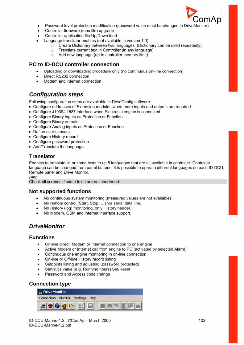
ID-DCU-Marine-1.2, ©ComAp – March 2005 102 ID-DCU-Marine-1.2.pdf
• Password level protection modification (password value must be changed in DriveMonitor) • Controller firmware (mhx file) upgrade • Controller application file Up/Down load
• Language translator enables (not available in version 1.0) o Create Dictionary between two languages (Dictionary can be used repeatedly) o Translate current text in Controller (in any language) o Add new language (up to controller memory limit)
PC to ID-DCU controller connection • Uploading or downloading procedure only (no continuous on-line connection) • Direct RS232 connection • Modem and internet connection
Configuration steps Following configuration steps are available in DriveConfig software: • Configure addresses of Extension modules when more inputs and outputs are required • Configure J1939/J1587 interface when Electronic engine is connected • Configure Binary inputs as Protection or Function • Configure Binary outputs • Configure Analog inputs as Protection or Function • Define user sensors • Configure History record • Configure password protection • Add/Translate the language
Translator Enables to translate all or some texts to up 5 languages that are all available in controller. Controller language can be changed from panel buttons. It is possible to operate different languages on each ID-DCU, Remote panel and Drive Monitor. Hint: Check all screens if some texts are not shortened.
Not supported functions • No continuous system monitoring (measured values are not available) • No remote control (Start, Stop, …) via serial data line. • No History (log) monitoring, only History header. • No Modem, GSM and internet interface support.
DriveMonitor
Functions • On-line direct, Modem or Internet connection to one engine • Active Modem or Internet call from engine to PC (activated by selected Alarm) • Continuous one engine monitoring in on-line connection • On-line or Off-line History record listing • Setpoints listing and adjusting (password protected) • Statistics value (e.g. Running hours) Set/Reset • Password and Access code change
Connection type
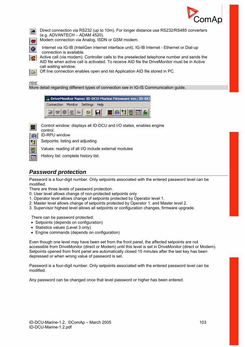
ID-DCU-Marine-1.2, ©ComAp – March 2005 103 ID-DCU-Marine-1.2.pdf
Direct connection via RS232 (up to 10m). For longer distance use RS232/RS485 converters (e.g. ADVANTECH – ADAM 4520).
Modem connection via Analog, ISDN or GSM modem.
Internet via IG-IB (InteliGen internet interface unit). IG-IB Internet - Ethernet or Dial-up connection is available.
Active call (via modem). Controller calls to the preselected telephone number and sends the AID file when active call is activated. To receive AID file the DriveMonitor must be in Active call waiting window.
Off line connection enables open and list Application AID file stored in PC.
Hint: More detail regarding different types of connection see in IG-IS Communication guide.
Control window: displays all ID-DCU and I/O states, enables engine control.
ID-RPU window
Setpoints: listing and adjusting
Values: reading of all I/O include external modules
History list: complete history list.
Password protection Password is a four-digit number. Only setpoints associated with the entered password level can be modified. There are three levels of password protection. 0. User level allows change of non-protected setpoints only 1. Operator level allows change of setpoints protected by Operator level 1. 2. Master level allows change of setpoints protected by Operator 1. and Master level 2. 3. Supervisor highest level allows all setpoints or configuration changes, firmware upgrade. There can be password protected: • Setpoints (depends on configuration) • Statistics values (Level 3 only) • Engine commands (depends on configuration)
Even though one level may have been set from the front panel, the affected setpoints are not accessible from DriveMonitor (direct or Modem) until this level is set in DriveMonitor (direct or Modem). Setpoints opened from front panel are automatically closed 15 minutes after the last key has been depressed or when wrong value of password is set. Password is a four-digit number. Only setpoints associated with the entered password level can be modified. Any password can be changed once that level password or higher has been entered.
ID-DCU-Marine-1.2, ©ComAp – March 2005 104 ID-DCU-Marine-1.2.pdf
Modbus protocol • Direct connection: RS232, RS422, RS485 • Modem connection • 9600, 19200 or 38400 bps, 8 data bits, 1 stop bit, no parity • Transfer mode RTU • Function 3 (Read Multiply Registers) • Function 6 (Write Single Register) • Function 16 (Write Multiply Registers) • The response to an incoming message is sent with minimum 4.096 ms delay after message reception The complete description of Modbus communication protocol can be found in Modbus Protocol Reference Guide PI-MBUS-300 and Open Modbus Specification Release 1.0. Both documents are available from web site at http://www.modicon.com/openmbus/ .
Modbus Multipack message It is special communication object that contains all values that are used for History record (configurable) and can be read by one command. Hint: Detail Modbus command description see in ComAp Communication guide.
Communication object vs. Register All the data intended for communication has its representation as communication objects in the controller. The communication object is represented by the n-byte array in the controller memory and identified by the unique 16-bit communication object number. The register, according to Modbus communication protocol, represents a two-byte data and in communication functions is referenced by 16-bit register address. Further in the description of communication functions the communication object number will always be used as a register address and length of the communication object will be expressed by number of registers. Just one communication object can be read or written by one communication function. Hint: It is possible to download the Actual InteliDrive controller object description corresponding to actual configuration from on-line controller or from aid archive using DriveConfig software.

ID-DCU-Marine-1.2, ©ComAp – March 2005 105 ID-DCU-Marine-1.2.pdf
Technical data
ID-DCU
Power supply Voltage range 8-36V DC Current consumption (depends on supply voltage) 0,34A at 8VDC
0,12A at 24VDC 0,09A at 36VDC
Battery voltage measurement tolerance 2 % at 24V RTC battery life-cycle 10 year Hint: RTC battery flat causes wrong Date&Time information only.
Operating conditions Operating temperature ID-DCU -20 to +70 °C Operating temperature ID-DCU-LT -40 to +70 °C Storage temperature -30 to +80 °C Humidity 95% without condensation Flash memory data retention time 10 years Protection front panel IP65 Standard conformity Low Voltage Directive EN 61010-1:95 +A1:97 Electromagnetic Compatibility EN 61000-6-2, October 2001
EN 61000-6-4, October 2001 IEC 60533, Ed. 2; 1999-11
Vibration 5 - 25 Hz, ±1,6mm 25 - 100 Hz, a = 4 g
Shocks a = 200 m/s2
Dimensions and weight Dimensions (183x123x47mm)
See chapter terminals and dimensions Weight 800g
Binary inputs Number of inputs 14 Input impedance 4,7 kΩ Input range 0-36 VDC Switching voltage level for close contact indication 0-2 V Max voltage level for open contact indication 8-36 V
Binary open collector outputs Number of outputs 14 Maximum current (outputs BO1, BO2) 1A Maximum current (outputs BO3 - BO14) 0,5 A Maximum switching voltage 36 VDC
Speed pick-up input Type of sensor magnetic pick-up (connection by shielded cable is recommended) Input impedance 10 kΩ Minimum input voltage 2 Vpk-pk (from 4 Hz to 4 kHz) Maximum input voltage 50 Veff Minimum measured frequency 4 Hz
ID-DCU-Marine-1.2, ©ComAp – March 2005 106 ID-DCU-Marine-1.2.pdf
Maximum measured frequency 10 kHz (min. input voltage 6Vpk-pk) Frequency measurement tolerance 1,5 %
D+ function Max. D+ output current 300 mA. Guaranteed level for signal Charging OK 90% of supply voltage.
Analog inputs Not electrically separated Group 1 AI1 – AI4 Number of inputs 4 unipolar Resolution 10 bits Jumper selectable range V, ohm, mA Maximal resistance range 2500 Ω Maximal voltage range 1,0 V Maximal current range 0 – 20 mA Input impedance 180 Ω for mA measuring Input impedance > 100 kΩ for V measuring Resistance measurement tolerance ± 2 % ± 2 Ω out of measured value Voltage measurement tolerance ± 1 % ± 1mV out of measured value Current measurement tolerance ± 1 % ± 0,5mA out of measured value Group 2 AI5 – AI8 Number of inputs 4 bipolar Resolution Up to 16 bits Jumper selectable range V, ohm, mA, thermo coupler Maximal resistance range 2500 Ω Maximal voltage range ± 1000 mV or 100mV The maximal input voltage ofset is in the range from –2 to +5 VDC against controller minus power supply when AI5 to AI8 is used for differential voltage measuring. Maximal current range ± 0 - 20 mA active 0 - 20 mA passive Input impedance 50 Ω for mA measuring Input impedance > 100 kΩ for V measuring Resistance measurement tolerance ± 0,5 % ± 2 Ω out of measured value Voltage measurement tolerance ± 0,5 % ± 1mV out of measured value Current measurement tolerance ± 0,5 % ± 0,5mA out of measured value
RS232 interface Maximal distance 10m Speed 19.2kBd
CAN bus interface Maximal CAN bus length Basic setting: CAN bus mode = 32C 200m Basic setting: CAN bus mode = 8C 900m Speed (32C) 250kBd Speed ( 8C) 64kBd Nominal impedance 120Ω Cable type twisted pair (shielded) Following dynamic cable parameters are important especially for maximal 200 meters CAN bus length and 32 ID-COM units connected: Nominal Velocity of Propagation min. 75% (max. 4,4 ns/m) Wire crosscut min.0,25 mm2 Maximal attenuation (at 1 MHz) 2 dB / 100m

ID-DCU-Marine-1.2, ©ComAp – March 2005 107 ID-DCU-Marine-1.2.pdf
Recommended Industrial Automation & Process Control Cables: BELDEN (see http://www.belden.com):
• 3082A DeviceBus for Allen-Bradley DeviceNet • 3083A DeviceBus for Allen-Bradley DeviceNet • 3086A DeviceBus for Honeywell SDS • 3087A DeviceBus for Honeywell SDS • 3084A DeviceBus for Allen-Bradley DeviceNet • 3085A DeviceBus for Allen-Bradley DeviceNet • 3105A Paired EIA Industrial RS485 cable
LAPP CABLE (see http://www.lappcable.com)
• Unitronic BUS DeviceNet Trunk Cable • Unitronic BUS DeviceNet Drop Cable • Unitronic BUS CAN • Unitronic-FD BUS P CAN UL/CSA
ID-RPU
Power supply Voltage range 8 - 36V DC Binary inputs Number of inputs Sd1 – Sd5 5 (broken wire detection, 10 kΩ required) Input resistance 1 kΩ Input range 0 - 5 VDC Switching voltage level for close contact indication 0 - 1,5 V Max voltage level for open contact indication 3 - 4,5 V Voltage range for broken wire indication 4,5 - 5 V Resistance limit for broken wire detection 20 kΩ Emergency stop input (normally closed) 1 (no BW detection)
Speed pick-up input Type of sensor magnetic pick-up (connection by shielded cable is recommended) Input impedance 10 kΩ Minimum input voltage 2 Vpk-pk (from 4 Hz to 4 kHz) Maximum input voltage 50 Veff Minimum measured frequency 4 Hz Maximum measured frequency 10 kHz (min. input voltage 6Vpk-pk) Frequency measurement tolerance 1,5 %
Solenoid driver (power) outputs Galvanic separated separate terminals for ± supply Number of outputs 2 (Fuel solenoid, Stop solenoid) Maximum current 8 A DC (one channel only) Maximum current 12 A DC (both channels together) Supply voltage range 8 - 36 VDC Protections OFF-STATE Broken wire (open circuit) detection ON-STATE Short circuit Overload (switch-overheat detection)
Lost of power supply indication
Binary outputs Number of outputs 2 (fix function: Warning and Shut down) Maximum switching voltage 36 VDC Maximum current 0,5 A