Embed Size (px)
Citation preview

IAERI/TR-712/96 KR9600256
Integrated Plant Inf orfflation Technology
Design Support Functionality
VOL

KAERI/TR-712/96
Integrated Plant Information Technology
Design Support Functionality
"Integrated Plant Information Technotogy Design Support Functionality"^
1996^
X] X\ : ^ C|j £j
P.W. Barber
D. Goland
Si ef §
\T= CANDU 9 ^7||
M& f̂lu+cf ^aJ«*gAjo| AECL (Atomic Energy Canada Limrted)oflAf
CANDU 3 5 £ ^ E f
S S A|£Bfoj Process Engineerings b|^f^ |&c M<H, Mechnical
^ a^o f SsHAffe =g^ }e i * ! # S t e ^ (Information lsland)« ^ ^ s f o ^ ^0.14
CAE (Computer Aided Engineering)^ ^ o j s S ^ ^ ^ ^ CHO|E|AISJ^
s|2ip. CANDU 9 ^7j | E f^^^Ah °i^5!fxJloi
AECL MH 2f MON^I A ^ s f o i 2ife CAE Tool
I S ^ ^ S ^ * g M^4. S ^ CAE ^^011 g f i i f a ^ A ^ , aBiJ l CANDU 9S
large CANDU ^T«A | ^ T | S > + ^ O | | nHsj Korean Requirements %
Abstract
This technical report was written as a result of Integrated Plant Information System
(IPIS) feasibility study on CANDU 9 project which had been carried out from January,
1994 to March, 1994 at AECL (Atomic Energy Canada Limited) in Canada. From 1987,
AECL had done endeavour to change engineering work process from paper based work
process to computer based work process through CANDU 3 project. Even though AECL
had a lot of good results from computerizing the Process Engineering, Instrumentation
Control and Electrical Engineering, Mechnical Engineering, Computer Aided Design and
Drafting, and Document Management System, but there remains the problem of
information isolation and integration. On this feasibility study, IPIS design support
functionality guideline was suggested by evaluating current AECL CAE tools, analyzing
computer aided engineering task and workflow, investigating request for implementing
integrated computer aided engineering and describing Korean request for future CANDU
design including CANDU 9.
Assessment Design
Integrated Plant InformationTechnologyDesign Support Functionality
CANDU 9
KAERI/TR 1994 69-01100-ASD-001Revision 0
KAERIKorea Atomic Energy Research InstituteP.O. Box 105, YusongTaejeon, Korea 305-600
1994 October
CONTROLLED
This document and theinformation contained in it hasbeen made available for usewithin your organization andonly for specified purposes.No part of this document norany information contained init may be transmitted in anyform to any third partiesexcept with prior writtenconsent.
Octobre 1994
CONTROLE
Le present document et lesrenseignements qu'il contentont ete mis a la disposition davotre organisation aux finsprecisees seulement. Aucuneparts du present document niaucun renseignement qu'ilcontent ne doivent direbonnes ou communiques hdes tiers, sous quelque fonnaque ce soit, sans I'autorisationprealable ecrfte.
AECL EACLAECL CANDU2251 Speakman DriveMississauga, OntarioCanada L5K1B2
EACL CANOU2251, rue SpeakmanMississauga (Ontario)Canada L5K1B2
MJIS] I 9711-CV / 69-ASD / 94-1 ? -02

© Atomic Energy of Canada Limited © Energie atomique du Canada limiteeKorea Atomic Energy Research Institute Korea Atomic Energy Research Institute
Assessment Design
Integrated Plant InformationTechnologyDesign Support Functionality
KAERI/TR 1994
CANDU 9
69-01100-AS D-001Revision 0
Prepared by ARedige par /V
Approved byApprouve par
Y.S. KirMD.J. KimCANDU 9
S.D. SukEngineering ManagerKAERI Toronto Operations
4
Prepared byRedige par
Reviewed byVerifie par
Approved byApprouve par
Accepted by^--Accept^-par^
P.W. Barber/D. GolandEngineering Tools and Methods
JR. PopovicCANDU 9
S.A. Usmani iCANDU 9/ // } /
///•if/It*— • "
R.A. Olmstead. C&l DirectorCANDU 9
KAERIKorea Atomic Energy Research InstituteP.O. Box 105, YusongTaejeon, Korea 305-600
1994 October
CONTROLLED
AECLAECL CANDU2251 Speakman DriveMississauga, OntarioCanada L5K1B2
Octobre 1994
CONTROLE
EACLEACL CANDU2251, rue SpeakmanMississauga (Ontario)Canada L5K1B2
94209I /97(LCN/6<< ASD/9J 111);
AEOLRelease and Liste des documentsrevision history et des revisions
Document Details / Details sur te document
Relea se and Revision History / Liste des documerits et des revisionsI
Release / Document Revision / Revision Purpose of Release*; Details of Rev./AmendmentObjet du document; details des rev. ou des modif.
N0./N0 Date No./N0 Date
AECLCANDU EACLCANDU
Title / Titre
Integrated Plant Information Technology Design Support Functionality
Approval StatusEtat de I'approbatiort
A
Total no. of pagesN1*™ total de pages
Prepared byRedige par
Reviewed byExamine par
Approved byApprouve par
94-07-08
94-10-06
94-11-25
Dl
D2
94-07-06
94-10-04
94-11-02
Review & Comment
Review & Comment
Issued as 'Approved for Use'
DCS/RMS Input / Donnees SCO ou SGD
P.W. BarberY.S. KimD.J. Kim
P.W. BarberD. GolandY.S. KimD.J. Kim
P.W. BarberD. GolandY.S. KimD.J. Kim
J.R. Popovic
J.R. Popovic
J.R. Popovic
S.A. Usmani
S.A. Usmani
S.A. Usmani
Rel. Pro|. ProjectProj. conn. Projet SI
I 69 I 69Section
SerialSerie
SheetFeuilleNo.N°
Codes
Of Ret.Ret.
Sec.Sect.
Dist.Distr. Source
01100 ASD 003 999 °°1 X999
Unit No.(s)Tranche
0 1 2 3 45 6 7 8
Trti°
I
69-01100-ASD-001 Page i
Rev. 0
TABLE OF CONTENTS
SECTION PAGE
1. SCOPE 1-1
1.1 Background 1-11.2 Document Overview 1-1
2. PURPOSE 2 - 1
3. AECL'S COMPUTER-AIDED ENGINEERING TOOLS 3 - 1
3.1 Civil/Structural CAE Tools 3-43.1.1 ModelDraft (MDR) 3 - 53.1.2 MicasPlus Analysis (MPA) 3-73.1.3 MicasPlus Design 3 - 83.1.4 STARDYNE, ANSYS and PATRAN 3 - 93.1.5 Software for Embedded Parts 3 - 1 03.2 Process Engineering 3 - 1 03.2.1 Intergraph's PDS P&ID 3 - 1 03.2.2 PD_Design for Piping Modelling 3 -113.2.3 PD_EQP for Equipment Modelling 3 - 1 23.2.4 PE_HVAC for Heating, Ventilating and Air Conditioning Ducts . . . . 3 -123.2.5 PDS Equipment Definition (EQ) 3 - 1 33.2.6 PD_Stress 3 - 1 33.2.7 Piping Stress Analysis Interface (PSA) 3 - 1 43.2.8 NUCIRC, P-Tran, Alitig for Thermalhydraulics 3 - 1 43.2.9 Nuclear Pipe Support Restraint (NPSR) 3 - 1 43.2.10 Piping Stress Analysis ADLPIPE 3 - 1 53.2.11 PDJso and ISOGEN for Isometric Extraction 3 - 1 53.2.12 PD_Report for Piping Material Take-Off 3 - 1 53.3 Instrumentation Control & Electrical (ICE) Engineering 3 - 1 53.3.1 EE_Power for One-line Diagrams 3 - 1 63.3.2 EE_Schematic for Elementary Diagrams 3 - 1 63.3.3 EE_WPD for Block Diagrams 3 - 1 83.3.4 EE_Raceway for Raceway Design 3 - 1 83.3.5 Instrument Loop Diagrams (Intergraph PDS P&ID) 3 - 1 93.3.6 PDS IN (or IDN) for Instrument Data 3 - 1 93.3.7 Engineering Modelling System (EMS, PDM/PDU) 3-203.3.8 IntEC 3-213.4 Mechanical Engineering 3 -27
69-ASDW/l 1/1)3
69-01100-ASD-001 Page ii
Rev. 0
TABLE OF CONTENTS
SECTION PAGE
3.4.1 Pro/Engineer 3 - 2 73.4.2 EMS 3 -273.4.3 PATRAN/ANSYS/STARDYNE for Stress Analysis 3 -273.5 Inter-Disciplinary CAE Tools 3 -273.5.1 PD_Clash for Clash Checking 3 - 2 83.5.2 Design Review and Model View for Model Walk-Through
and Illustration 3 - 2 83.5.3 PD_Draw for the Extraction of Orthogonal Drawings 3 - 2 93.5.4 CANDU Material Management System (CMMS) 3 - 2 9
4. ENGINEERING TASKS AND WORK PROCESS WITH CAE 4 - 1
4.1 Pre-Engineering 4 - 14.2 Project-Specific Planning and Staff Identification 4 - 14.2.1 Progress Reporting 4-2
4.2.2 Coordination of CADDS Work 4-34.3 Project Set up on the Network 4 - 34.3.1 Design Areas 4-44.3.2 Model 'By-System' versus 'By-Area', and Models 'By-Size-Range' 4-44.3.3 Coordinate Systems 4 - 54.3.4 InteEC Project Setup 4-54.3.5 CMMS Project Setup 4 - 54.4 Civil Engineering 4 - 5
4.4.1 Structural/Civil Modelling 4-54.4.2 Model Verification and Propagation 4-64.4.3 Steel Catalogues 4-64.4.4 Embedded Parts for Penetrations 4-64.4.5 Steel GA Drawings 4 - 74.4.6 MTO for Steel and Concrete 4 - 74.4.7 Structural Stress Analysis and Design 4-74.4.8 Detail Design 4-74.5 Process Engineering 4-84.5.1 P&ID, LL, EL, and VL 4 - 84.5.2 Piping Modelling 4 - 8
4.5.3 Inter-Module Hook-up Spools 4 - 84.5.4 Equipment Modelling 4-94.5.5 HVAC Modelling 4-94.5.6 Piping/Equipment GA Drawings 4 - 9
W-ASD
69-01100-ASD-001 Page iii
Rev. 0
TABLE OF CONTENTS
SECTION PAGE
4.5.7 Piping Reports 4-94.5.8 Pipe Supports 4-94.5.9 Piping Isometrics 4 - 1 04.5.10 Piping Stress Analysis 4 - 1 04.5.11 Thermo-Hydro-Dynamic Analysis 4 - 1 04.5.12 Piping Reference Database (RDB) 4 - 1 04.6 Instrumentation, Control & Electrical Engineering (ICE) 4 - 1 14.6.1 Electrical Raceways 4 - 1 14.6.2 Tray Catalogues 4 -114.6.3 Tray Supports 4 - 1 14.6.4 Tray Support Stress Analysis 4 - 1 14.6.5 Tray Material Take-off 4 - 1 14.6.6 Tubing Modelling 4 -114.6.7 Tubing Supports 4 - 1 24.6.8 Tubing Isometrics and BOM 4 - 1 24.6.9 Tubing Stress Analysis 4 - 1 24.6.10 Electrical Panels, Instruments Racks and Lighting Fixtures 4 - 1 24.6.11 Electrical GA Drawings 4 - 1 24.6.12 Instrument Loop Diagrams 4 - 1 24.6.13 One-line Diagrams and Electrical Analysis 4 - 1 24.6.14 Elementary Diagrams 4 - 1 34.6.15 Cable Block Diagrams 4 - 1 34.6.16 Cabling and Wiring Reports 4 - 1 34.6.17 Electrical Structures and Devices Reports 4 - 1 34.7 Mechanical and Fuel Handling Engineering 4 - 1 34.7.1 Clash Checking of Mechanical Items 4 - 1 34.7.2 Mechanical Drawings and BOM 4 - 1 34.7.3 Stress Analysis for Mechanical Items 4 - 1 34.7.4 Interface with N.C 4 - 1 44.8 Clash Management 4 - 1 44.8.1 Clash/Freeze Cycle 4 - 1 44.8.2 Clash Envelopes for Deflection/Deformation 4 - 1 64.9 Walk-Through and Design Review 4 - 1 64.10 Pictures for Marketing and Illustrations 4 - 1 64.11 Material Management 4 - 1 64.11.1 Material Demand and BM's 4 - 1 64.11.2 Material Supply and EQR's 4 - 1 7
94209I/97IHS69-ASD94/1I/TO
69-01100-ASD-001 Page iv
Rev. 0
TABLE OF CONTENTS
SECTION PAGE
4.12 Network Operations 4 - 1 74.13 Software/Hardware Vendor Support 4 - 1 8
5. FUTURE DEVELOPMENT AND RECOMMENDATIONS 5 - 1
5.1 New Hardware and Operating System: Intel/Windows NT 5 - 15.2 Plant Construction and Commissioning 5 - 15.2.1 Walk-Through, Drawings and Progress Monitoring 5 - 15.2.2 Construction Simulation 5 - 25.2.3 Computer-Aided Manufacturing (CAM) 5 - 25.3 Plant Operation, Maintenance, Administration and Decommissioning . . . 5-25.4 Future Engineering Design Tools 5-55.4.1 Civil 5 - 55.4.2 Process 5 - 55.4.3 Instrumentation Control and Electrical (ICE) 5 - 55.4.4 Mechanical 5 - 65.4.5 Non-Discipline 5 - 6
ILLUSTRATIONS
Figure 3-1 AECL Design Software 3 - 2Figure 3-2 PDS Modules 3 - 3Figure 3.1-1 MicasPlus Environment 3 - 6Figure 3.3.8-1 IntEC Software Modules 3 -22Figure 4.8.1-1 Clash Resolution 4 - 1 5Figure 5.3-1 Plant Design Management Software, CAE and Photogrammetry 5 - 4
APPENDICES
Appendix A Korean Requirements A -Appendix B State-of-the-Art Computer-Aided Engineering Technology B -Appendix C Tool in use at Mitsubishi and at EDF C -Appendix D Rack and Panel Design with EMS and PDM/PDU D -Appendix E CMMS Software E -Appendix F Abbreviations and Acronyms F -Appendix G AECL Computer Codes: Physics and Other G -
69-ASD94/il/OJ
69-01100- ASD-001 Page 1 - 1
Rev. 0
1. SCOPE
This document enumerates all the existing tools that are used in Computer-AidedEngineering (CAE) at AECL CANDU, and illustrates how these tools are being used.Recommendations are made for future development and use of new CAE.
1.1 BACKGROUND
AECL is a long-time developer and user of computer-aided engineering tools. By1980 CAE tools had been in use on the CANDU 6 and other projects for approximately adecade. During that period, the computer-aided engineers and the software developers workedin isolation, with no coordination or integration between the different disciplines. Such toolsincluded analysis software for piping hydraulics and stress (e.g., TPIPE, NUPIPE), civil andstructural stress analysis (ANSYS, STARDYNE, STRUDL), cable management (DICON), andcomputerized bills-of-materials (PMMIS). In the mid-1980's a computer-aided drafting anddesign system (CADDS) was added to the list of tools at AECL, initially for 2-D drafting.
A significant development took place later in the 1980's when CANDU 3 designstarted. At that time the concept of CANDU Integrated Design (CANDID) was introduced, totie together the emerging use of 3-D modelling, the existing 2-D drafting, database management,and engineering analysis. At the same time AECL set up the General Purpose Computer Ring(GPCR) for integrated document management including text and graphics. GPCR is used fordocument generation, revision control, reference information (procedures and standards), as wellas for engineering analysis.
The process of integrating CAE is still evolving, as additional tool are beingintroduced. This document covers mainly CAE at its present state in AECL, with a view ofprojected developments in the near and distant future.
1.2 DOCUMENT OVERVIEW
The CAE tools currently in use or in testing are listed and described in Section 3.The main CANDU project deliverables, together with the work methods used for producingthese deliverable, are described in Section 4. These new work methods are dictated by the use ofthe advanced CAE tools.
In Section 5, this document indicates our direction for the future, when additionaltools are developed or procured, which will allow us to design and build the next generationCANDU plant with improved quality, reduced cost, and a shorter schedule. Recommendationsare made regarding the incorporation of such future tools into CAE in order to achieve theseobjectives.
AECL's objectives are also to reduce costs and to improve the quality of theCANDU plant during its operation and maintenance. Section 5 discusses how new tools ofIntegrated Plant Information Technology will enable us to achieve these objectives.
69-isd94/1 MB

69-01100-ASD-001 Page 1-2
Rev. 0
The specific requirement by Korean owners/designers of CANDU plants, withregard to plant information management, are presented in Appendix A. Also in the Appendices,the reader will find a list of features in current CAE technology, details of software in use in thenuclear industry outside AECL, and details of future use of software for electric panel design.Appendix G describes several computer codes, developed by AECL. Some of the codes are notintegrated into CAE.
Throughout the document, a clear distinction is made between tools that arealready in place, and those which are planned for the future.
W-asdM/ll/IC

69-0il00-ASD-001 Page 2 - 1Rev. 0
2. PURPOSE
This document is written as a part of the joint studies by KAERI and AECL,designated to establish requirements for future CANDU units in Korea. The report will enablethe reader to acquire familiarity with CAE usage in the Canadian CANDU program, whileparticipating in next-generation CANDU development. KAERI staff will also be able tocompare the Korean requirements for plant information tools with those used at AECL.
This document will help in establishing present uses and future needs forcomputer-aided engineering tools designated to reduce engineering costs, increase engineeringquality, and improve the interface between Engineering and Construction. The objective is tofurther increase integration and standardization, with a goal in mind to achieve a fully integratedplant information system, that will accompany the plant throughout its life-cycle: from theplant's inception, through its construction and operation, to its decommissioning.
942091/S70-C969 udw/u/o:
69-01100-ASD-001 Page 3 - 1
Rev. 0
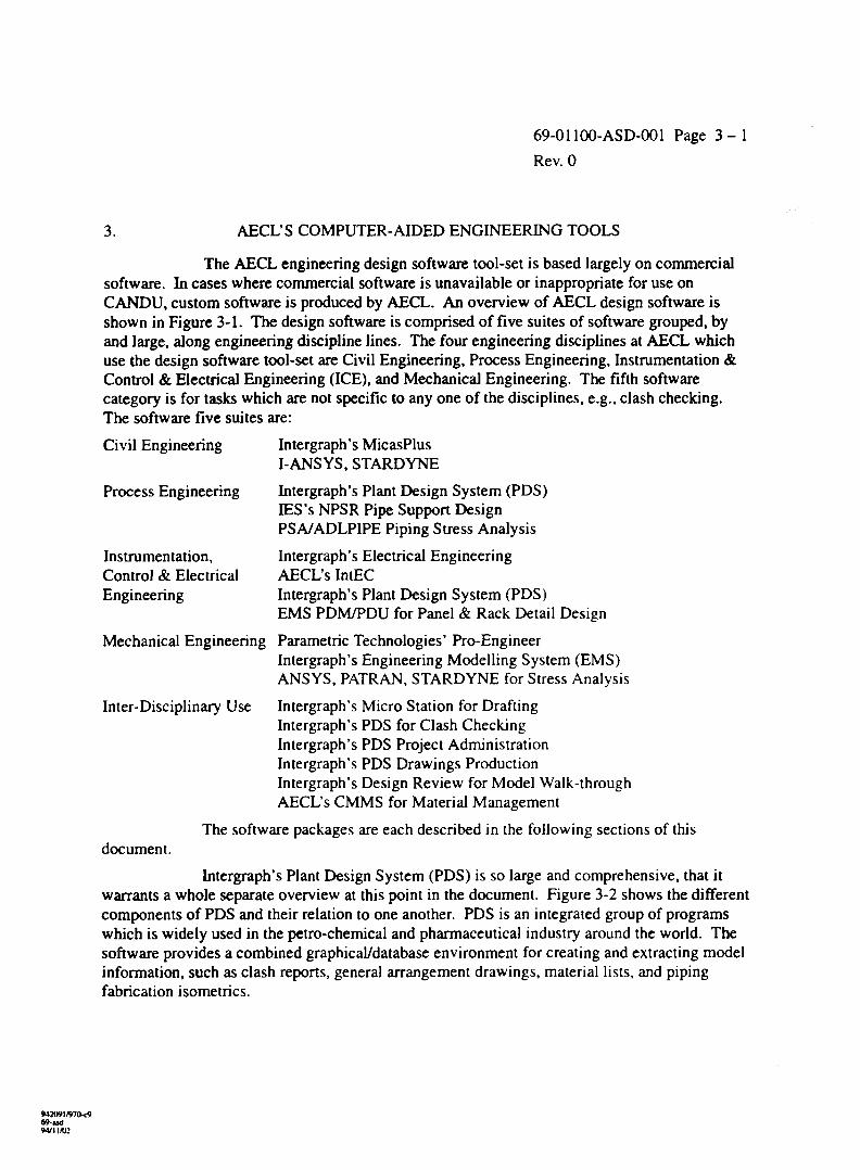
3. AECL'S COMPUTER-AIDED ENGINEERING TOOLS
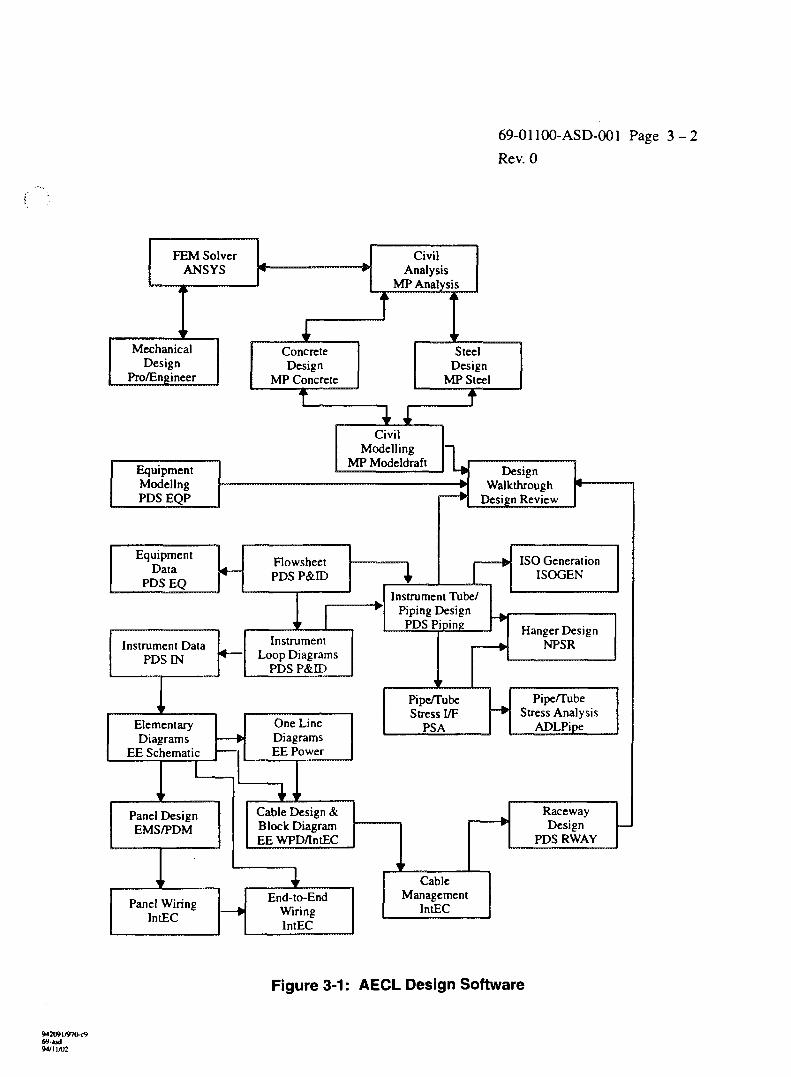
The AECL engineering design software tool-set is based largely on commercialsoftware. In cases where commercial software is unavailable or inappropriate for use onCANDU, custom software is produced by AECL. An overview of AECL design software isshown in Figure 3-1. The design software is comprised of five suites of software grouped, byand large, along engineering discipline lines. The four engineering disciplines at AECL whichuse the design software tool-set are Civil Engineering, Process Engineering, Instrumentation &Control & Electrical Engineering (ICE), and Mechanical Engineering. The fifth softwarecategory is for tasks which are not specific to any one of the disciplines, e.g., clash checking.The software five suites are:
Civil Engineering Intergraph's MicasPlusI-ANSYS, STARDYNE
Process Engineering Intergraph's Plant Design System (PDS)IES's NPSR Pipe Support DesignPSA/ADLPIPE Piping Stress Analysis
Instrumentation, Intergraph's Electrical EngineeringControl & Electrical AECL's IntECEngineering Intergraph's Plant Design System (PDS)
EMS PDM/PDU for Panel & Rack Detail Design
Mechanical Engineering Parametric Technologies' Pro-EngineerIntergraph's Engineering Modelling System (EMS)ANSYS, PATRAN, STARDYNE for Stress Analysis
Inter-Disciplinary Use Intergraph's Micro Station for DraftingIntergraph's PDS for Clash CheckingIntergraph's PDS Project AdministrationIntergraph's PDS Drawings ProductionIntergraph's Design Review for Model Walk-throughAECL's CMMS for Material Management
The software packages are each described in the following sections of thisdocument.
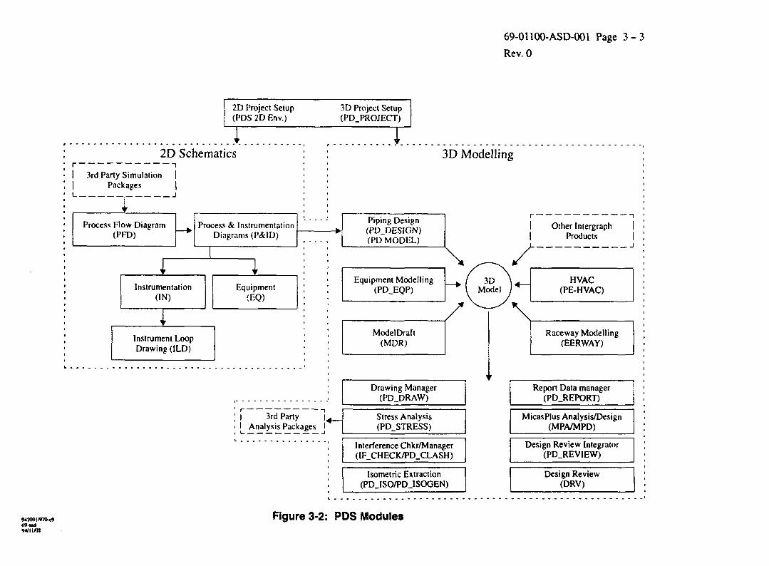
Intergraph's Plant Design System (PDS) is so large and comprehensive, that itwarrants a whole separate overview at this point in the document. Figure 3-2 shows the differentcomponents of PDS and their relation to one another. PDS is an integrated group of programswhich is widely used in the petro-chemical and pharmaceutical industry around the world. Thesoftware provides a combined graphical/database environment for creating and extracting modelinformation, such as clash reports, general arrangement drawings, material lists, and pipingfabrication isometrics.
69-ud94/11/U:
69-01100-ASD-001 Page 3 - 2
Rev. 0
FEM SolverANSYS
MechanicalDesign
Pro/Engineer
ConcreteDesign
MP Concrete
CivilAnalysis
MP Analysis
SteelDesign
MP Steel
EquipmentModelingPDS EQP
EquipmentData
PDSEQ
CivilModelling
MP Modeldraft
FlowsheetPDS P&ED
Instrument DataPDS IN
ElementaryDiagrams
EE Schematic
Panel DesignEMS/PDM
Panel WiringIntEC
InstrumentLoop Diagrams
PDS P&ID
One LineDiagramsEE Power
Cable Design &Block DiagramEE WPD/IntEC
End-to-EndWiringIntEC
DesignWalkthrough
Design Review
Instrument Tube/Piping Design
PDS Piping
ISO GenerationISOGEN
Hanger DesignNPSR
Pipe/TubeStress I/F
PSA
Pipe/TubeStress Analysis
ADLPipe
RacewayDesign
PDS RWAY
CableManagement
IntEC
Figure 3-1: AECL Design Software
69-udW/ll/02
69-01!00-ASD-001 Page 3 - 3
Rev. 0
2D Project Setup(PDS 2D Env.)
i2D Schematics
I 3rd Party Simulation I| Packages |i . i
Process Flow Diagram(PFD)
Process & InstrumentationDiagrams (P&ID)
941091/97IM469-ud94/11/02
Instrumentation(IN)
t
Instrument LoopDrawing (ILD)
r
Equipment(EQ)
3D Project Setup(PD_PROJECT)
I 3rd PartyI Analysis Packages
I3D Modelling
Piping Design(PD.DESIGN)(PD MODEL)
Equipment Modelling(PD_EQP)
ModelDraft(MDR)
Drawing Manager(PD_DRAW)
Stress Analysis(PD_STRESS)
Interference Chkr/Manager(IF_CHECK/PD_CLASH)
Isometric Extraction(PDJSO/PDJSOGEN)
Other Intergraph IProducts |
i
HVAC(PE-HVAC)
Raceway Modelling(EERWAY)
Report Data manager(PD.REPORT)
MicasPlus Analysis/Design(MPA/MPD)
Design Review Integrator(PD_REVIEW)
Design Review(DRV)
Figure 3-2: PDS Modules
69-01100-ASD-001 Page 3 - 4
Rev. 0
Process and Instrument Diagrams (P&ID)
Process Flow Diagrams (a sub-set of P & ID) (PFD*)
Piping modelling (PD_Design)
Heating Ventilating and Air Conditioning modelling (PE_HVAC*)
Electrical cable raceways modelling (EE_Raceway)
Equipment modelling (PD_EQP)
Civil/Structural modelling (ModelDraft, a sub set of MicasPlus)
Orthogonal drawings extraction (PD_Draw)
Clash (interference) detection (PD_Clash)
Piping fabrication isometrics (PD_Iso and ISOGEN)
Bills of materials, centre of gravity reports, Project reports (PD_Report)
Interface to piping stress analysis (PD_Stress)
Piping specs and catalogues reference data (PD_Data)
Instrument specifications (IN* or IDM*)
Equipment specifications (EQ*) - not yet developed
Design Review integrator for data transfer PDS-to-Design Review (PD_Review)
PDS project administration, creation, backups (PD_Project)
Software packages which are closely related to PDS but not sold as part of it are:
Structural stress analysis and design (MicasPlus)
Walk-through for the 3-D model (Design Review)
To understand where AECL stands within the Plant Engineering community inthe use of CAE, additional information is attached in Appendices B and C:
Appendix B gives a general overview of state-of-the-art Computer-AidedEngineering technology.
Appendix C describes other tools in the nuclear power industry which are usedfor the design, operation and maintenance of nuclear power plants.
3.1 CIVIL/STRUCTURAL CAE TOOLS
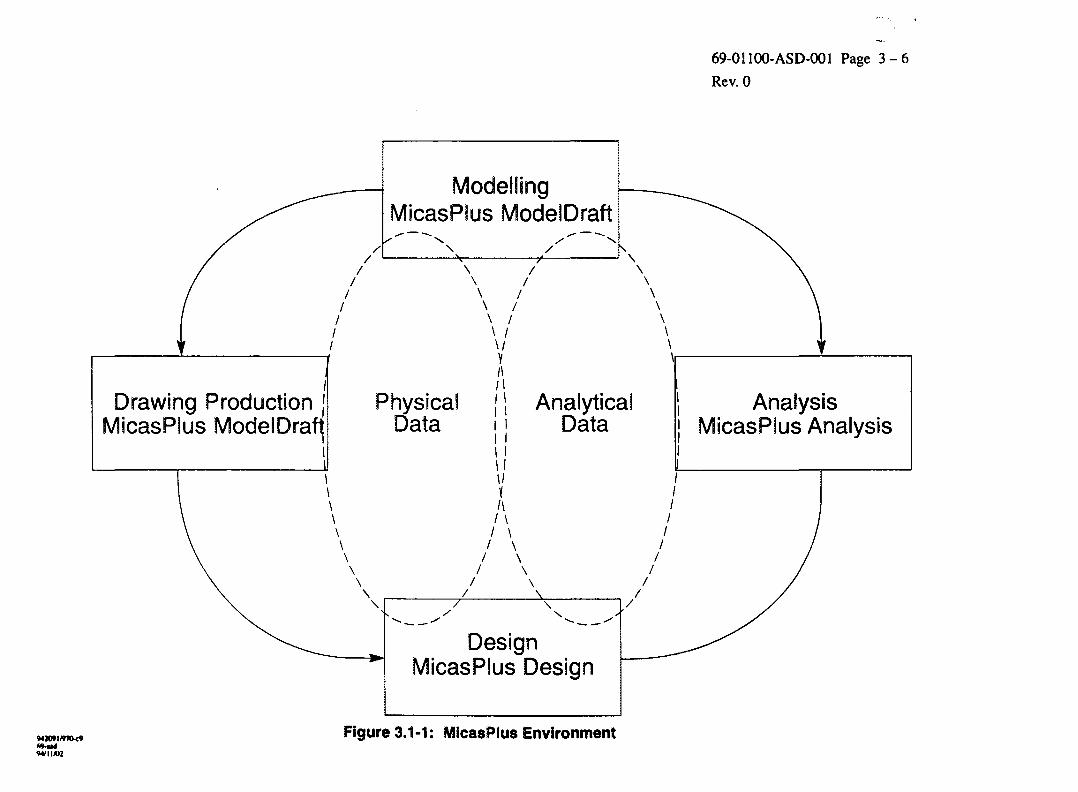
Computer-Aided Engineering tools for Civil/Structural Engineering at AECLCANDU are based partially on the Intergraph MicasPlus Environment. The MicasPlusEnvironment is a Micro Station based product which runs on Intergraph's CLIX work-station(Intergraph's Clipper computer chip + UNIX operating system). As shown in Figure 3.1-1MicasPlus is comprised of three main divisions: MicasPlus Model Draft (MDR), MicasPlusAnalysis (MPA), and MicasPlus Design (MPD). A Project Structural Database (PSD) allows thetransfer of information among the software divisions.
* The items mark with an asterisk are not currently in use at AECL.
942091/970-C969-asd
69-01100-ASD-001 Page 3 - 5
Rev. 0
Other tools in use, which are linked to MicasPlus but are independent of it, areANSYS and STARDYNE for stress analysis and design. Data is read from the MicasPlus modelinto ANSYS using the I-ANSYS interface to assure that the construction documents reflect theresults of the analysis and design. Some difficulties are still experienced in MicasPlus steeldesign according to Canadian Building Codes and in design of reinforced concrete andcomposite structures (steel plates with concrete).
3.1.1 ModelDraft (MDR)
ModelDraft is used for the creation of structural models, for the extraction ofmaterial reports and of steel general arrangement drawings, as well as for the management of theProject steel catalogue.
The modelling environment contains tools to allow efficient creation of 3-Dstructural models (for example place, edit, copy, move and modify structural components). Thedesigner works in as sparse model where each linear member (column, beam, brace) consists ofa single member line with section-graphics at its end. The sections are called up from a Projectsection table, and they may be selected manually or determined by the design software inMicasPlus Design. Area elements are used for plates, and walls, while volume elements are usedfor concrete of irregular shape. All elements carry information, such as section, material grade,length, cut-backs, and fire-proofing, which can be displayed on the screen.
Once the design is approved and the model data integrity is verified, it ispropagated (i.e., lines are automatically made into surfaces) for use by other disciplines (Processand ICE) as reference, and for walk-through sessions. The model is used also for clashchecking.
The drawing extraction environment is used for the definitions of steel layoutplans, sections and column schedules. Various member selection criteria and drawing formatsmay be set up.
Extracted reports include bills of materials, surface areas, weights, buoyancyand centre-of-gravity. The formats of the reports can be customized.
Steel sections table (InterSect) software module allows sections to be added,deleted and modifies. Arbitrary sections may be added as well. Standard steel section tables aredelivered with the software, including Canadian, US, European, Japanese, Australian, and UKsteel. To assure material standardization (for the reduction of the variety of procured sections), aproject-specific table can be built with a limited selection of sections.
942091/»7O*969-zsdW11/112
69-01100-ASD-001 Page 3 - 6
Rev. 0
MicasPlus ModelDraft
Drawing ProductionMicasPlus ModelDraflj
Physical [ \ AnalyticalData
AnalysisMicasPlus Analysis
DesignMicasPlus Design
Figure 3.1-1: MicasPlus Environment"M/II/UJ
69-01100-ASD-001 Page 3 - 7
Rev. 0
3.1.2 MicasPlus Analysis (MPA)
MicasPlus Analysis is a mathematic modelling system designed to build 3-Dmodels of buildings and structures for finite element analysis. MicasPlus Analysis is anIntergraph CLDC program which uses the graphics capabilities of Microstation. The sixcomponents of MicasPlus Analysis are:
- a three dimensional space in which models are created,
- an menu of finite elements to build the model,
- a system of boundary and loading conditions,
- tools to modify models and loads,
- tools to review and display analysis results,
- tools to perform pre-design operations.
MicasPlus Analysis interfaces with third-party analysis packages throughIntergraph's finite element neutral files. For compatibility with third party packages, MicasPlusdatabases can be created with non MicasPlus Analysis attributes. As noted earlier, MicasPlusAnalysis uses the Project Structural Database (PSD) as its interface to other MicasPlus products,MicasPlus Modeldraft and MicasPlus Design.
MicasPlus Analysis neutral file translator can convert either from a MicasPlusAnalysis model file to an ASCII neutral file or vice versa.
MPA has the following features:
Dual Interface:
Working Units:
Analysis Methods:
Modelling:
Material Definition:
Load representation:
MicasPlus Analysis provides both a graphics and an alphanumericinterface. Both interfaces include pre-processors, the applicableanalysis programs, modelling capabilities and printing and postprocessing of results.
As with MicasPlus Modeldraft, a MicasPlus Analysis can beperformed in either Imperial (feet and inches) or metric (metres andmillimetres) units.
MicasPlus Analysis can perform the user's choice of linear static,gap-hook static nonlinear, geometric static nonlinear, dynamic,response spectrum or linear time history analyses.
Model generation and modification features provide simple entry offinite element and frame models. The graphics interface gives a visualway for member placement and modification, load placement andreview.
MicasPlus Analysis allows definition of isotropic, orthotropic andanisotropic material property definitions.
MicasPlus Analysis permits application of a number of different loadtypes to a MicasPlus model, including concentrated, distributed,partial, trapezoidal, pressure, surface, traction, edge and body,specified displacements, initial stress, initial strain and temperaturechanges.
942091/970-c1)69-isd94/11/02
69-01100-ASD-001 Page 3 - 8
Rev. 0
Analysis Post-processor: MicasPlus Analysis provides a range of post processors with designand evaluation capabilities for civil and mechanical engineeringstructures. The post processors use results from finite element orframe analysis portions of the MicasPlus Analysis system.
Integration: MicasPlus Analysis can share data with other Intergraph structuralproducts using the PSD. MicasPlus Analysis can also create ASCIIneutral file for model translation to and from VAX based Rand/MicasAnalysis software, Intergraph workstation based I/FEM solver, or athird party analysis package. The ASCII neutral file can also be usedto create a MicasPlus Analysis model.
3.1.3 MicasPlus Design
At present, the use of MicasPlus Design is quite limited as described inSection 4.4.7, and in this section.
MicasPlus Design is an interactive post-processor that uses a Modeldraft orMicasPlus Analysis model and results to produce steel and concrete designs. MicasPlus SteelDesign provides a flexible way for describing the problem, performing the design and selectingresults for display or printing.
The features of MicasPlus Design are:
• Variety of Design Codes:
MicasPlus Steel Design is capable of designing steel structures using a variety of steel designcodes, including the Canadian, British, American and German design standards. Theaddition of the SI 6.1 code to the list of MicasPlus supported design codes was sponsored byAECL CANDU. However, Canadian Codes for the design of concrete and for compositestructures are missing from the software, significantly reducing the usability of MPD formost of the Large CANDU civil design.
• Steel Section Library:
MicasPlus Steel Design contains a standard steel section library. Sections can be placedoffset or rotated (See 3.1.1 for more detail).
• Design Modes:
Single members or groups of members can be analyzed using MicasPlus Design. Designcheck can be run on members with already-assigned sections.
• Default Models:
MicasPlus Design provides an ability to start modelling using default values as a basis for amodel.
• Design Parameters:
MicasPlus Steel Design provides the ability to assign individual members with individualdesign parameters including strength and deflection checks, user-defined bracingrequirements, code-dependent or code-independent design parameters and memberprocessing control options.
942091/970-cV69-isdW U A C
69-01100-ASD-001 Page 3 - 9
Rev. 0
• Design Tables:
User-defined tables are used by MicasPlus Design to provide material, deflection limit,alternate section and section criteria tables to control how sections are selected.
• Load Combination:
Specification MicasPlus Design allows definition of load combinations without having toreturn to MicasPlus Analysis.
• Effective Length (k) Factor Calculations:
Effective Length (k) Factors can be calculated by MicasPlus Design or can be defined by auser or can be selected from a table using member parameters.
• Material Take-Off:
MicasPlus Design provides the ability to create material take-off reports and design resultsreports from the model.
• Update Analysis:
MicasPlus Analysis element and material property tables can be updated from within SteelDesign based on group or independent design results.
• Design Post-processor:
MicasPlus Steel Design provides a range of methods for graphically displaying output fromdesign and analysis.
• Integration:
Communication with other MicasPlus products is provided via the Project StructuralDatabase.
• Analysis:
MicasPlus Steel Design provides the ability to re-analyze a MicasPlus Design model withoutreturning to MicasPlus Analysis.
3.1.4 STARDYNE, ANSYS and PATRAN
These are widely-used software packages for civil/structural and mechanicalstress analysis. Based on the finite-element method, they are used for the static and dynamicanalysis of structures and machines.
The key factor in proper use of these software packages (and any other softwarebased on finite-element theory, e.g., ADLPIPE), is the correct representation of the physicalstructure by the mathematical finite elements. This includes the correct selection of elementsand nodes, and the correct representation of restraints and loads.
Graphic and numeric user interfaces facilitate data entry and the review andevaluation of the results of the analysis. Plots of deformation and stress contours are producedfor this purpose. Import capabilities from solid modelling software packages allow the analysisof mechanical components and assemblies.
M2O9I/97O-C9
94/11/02
69-01100-ASD-001 Page 3 - 1 0
Rev. 0
A post-processor allows the combination of loads, but it does NOT perform Codeevaluation. In light of this, structural design, such as automatic section selection, plate sizing,and concrete re-bar sizing are not done in AECL through these software packages. It is expectedthat once MicasPlus selects steel sizes, STARDYNE and ANSYS will be used for designcertification.
3.1.5 Software for Embedded Parts
Software is currently under development in Saskatoon for managing embeddedparts, including a database which lists their numbers, location and items passing through them(e.g., pipe penetration) or attached to them (e.g., supports base plates). The software is based onthe EMS/PDM/PDU software described in Section 3.3.7. The software will be ready for use in1995.
No software is used for the detail-design of embedded parts.
3.2 PROCESS ENGINEERING
Intergraph's Plant Design System (PDS) is the core of the design tools which areused in Process Engineering for new CANDU design.
AECL has developed and adapted the following additional software suites tocomplement the capabilities of PDS:
- Nuclear pipe support design (IES/NPSR) also known as IES-Hanger.
- Nuclear piping stress analysis (PSA/ADLPIPE).
3.2.1 Intergraph's PDS P&ID
PDS P&ID is used for the creation of intelligent process and instrumentationdiagrams. P&ID stores graphic information in MicroStation files and alphanumeric data inrelational databases. The data includes equipment, piping and instrumentation required by heprocess, as well as the labels for items and of design/operating conditions.
In a typical session, the designer places graphics for equipment with nozzles andthen he/she connects the equipment items with piping. Valves and specialty items are thenplaced on the piping lines, followed by the definition of instrumentation loops and the placementof instrument items owned by these loops. The designer then places line attribute breaks, flowarrows, and labels for equipment, piping lines, and instruments.
The next step is propagation. The act of propagation serves to reads the textinformation from the graphic file and use it to populates the relational database. In this database(called "task database") the data change often, as the P&ID's are developed.
The 2-D reference database (RDB) governs the attributes of the graphics, thesymbols, and allowable values for alphanumeric information.
Once the data is complete, the designer posts the P&ID for Project use. In this,the P&ID data are copied into a second, more stable relational database (called "masterdatabase"), where it is made available for extraction of line lists, equipment lists, valve lists andinstrument lists. A 2-D RDB governs also the format of the lists.
942091/970-rt69-asd94/1 IXi:
69-01100-ASD-001 Page 3-11
Rev. 0
Another use for the P & ID is the transfer of information from it, into the 3-Dpiping model. The information consists of piping line information, such as spec., size, fluid,number, temperatures and pressures, which are loaded into the 3-D centre-line.
There is an option in the software to disable the use of "master database", so thatthe data are available to the Project directly from the "task database". AECL is using this option.
AECL has set up a special feature which is not included in the delivered software,as following: Around the main P&ID drawing border, eleven additional borders have beenplaced for Instrumentation Loop Diagrams (ILD). Special "invisible" (gapped) lines connect theinstrument pipe connection in the main P&ID with the ILD border. This maintains theconnectivity of the instrumentation graphics to the process graphics, but allows the plotting ofILD's separate from the P&ID.
3.2.2 PD_Design for Piping Modelling
PDS Piping is used to create and modify 3-D models of piping and tubingsystems, including in-line instrumentation and support location. PDS Piping stores projectlayout graphics in MicroStation graphic files, while the alphanumeric information, linked to thegraphics, is stored in relational databases. The data are used for clash detection,drawings/reports extraction, walk-through, and stress analysis.
During a typical modelling session, the designer routes intelligent pipecentre-lines which carry data. The data for the centre-line, such as line size, spec, pressures andtemperatures, come either from manual entry or directly form the P&ID. While he/she routes thecentre-line, the designer sees the all models from other disciplines and other designers' pipingand equipment models, so that he/she is able to visually fit the layout around objects alreadyplaced in the plant model and to connect to vessels' nozzles. The designer then calls up valves,and specialty items from the Reference Database, and places them in their proper locations onthe centre-line. The designer also situates fitting-to-fitting assemblies in the model. Finally, thesoftware places automatically all remaining fittings and pipes, as defined by the specs.
There are three databases for the Piping PDS application:
a. Piping/equipment Design Database, which holds all the instances of the modelcomponents, such as piping fittings, pipes, nozzles, and the associated data, e.g., wallthickness, material grade, and pressure rating. Each graphic component in the MicroStationfile is uniquely linked to an entry in the Design Database.
b. Piping Reference Database (RDB), which holds all piping specs and manufacturercatalogue information. The specs contain information regarding the allowable fittings,materials, sizes, etc. The RDB in its broader sense, in addition to the relational database, theRDB includes information in other formats (ASCII files and Intergraph library files), whichcontain, among other things, dimensional information, industry standards, Project standardsfor model graphics and messages, drawing labels, and piping component verbal descriptions.There are two copies of RDB data: an approved copy for project use, and an unapprovedcopy for the RDB developers' use.
<M 2091/9711-c969-ud94/11/1)2
69-01100-ASD-001 Page 3 -12
Rev. 0
c. Project Administration Database, which holds information about the way the Plant modelis partitioned into files, their location on the computer network, and the geographical locationthat the model in each file spans in the Plant. The location and description of models fromother disciplines is also stored here, to allow integrated tasks, such as clash check, drawingcomposition, and walk-through. This database also contains information about theorthogonal drawings which are defined in the project, the iso's that are extracted, the materialreports formats and content, as well as the information on clashes and their management.
It should be noted that where practical, the Piping application shares referencedata with the Schematic applications, such as P&ID. This sharing helps to ensure that consistentstandards are applied across a design project.
3.2.3 PD_EQP for Equipment Modelling
PDS PD_EQP is used for modelling equipment items such as pumps, heatexchangers, and vessels with nozzles which are connected to PDS piping models. This softwareis used also for modelling equipment for other disciplines such as electrical panels. The softwaredefines equipment volumes, for clash (interference) checking, for graphics to be placed inextracted drawings, and for walk-through sessions. The equipment volume may include only thephysical volume of the equipment, or also its maintenance and installation envelopes. Accesscorridors which are not associated with any specific equipment item are also modelled with PDSEQP. The clash checker will identify a "hard" clash with the physical equipment volume, and a"soft" clash with the reserved access envelope.
Equipment models are composed of graphics in MicroStation files, and fromalphanumeric data, which are stored in a relational database. The alphanumeric data include theequipment tags and descriptions, as well as the nozzles properties.
During a typical modelling session, the designer places primitive shapes, forexample, cylinders, cones and boxes, and groups them into equipment items (pumps, vessels,etc.). The dimensions and weights ares keyed in from manual equipment data sheets. Most ofthe nozzle information (such as flange outside diameter) is read directly from piping specs in thepiping Reference Database.
Parametrics are more complex modelling elements that can define entire pieces ofequipment. They are useful only during the preliminary design, when generic shapes aresufficient to define equipment.
3.2.4 PE_HVAC for Heating, Ventilating and Air Conditioning Ducts
The PDS HVAC application is included in a suite of software called "ProjectEngineer" (PE) by Intergraph. The software has been modified for compatibility with PDS.Apart from The layout capability found in PDS Piping, PDS HVAC also contains rules forHVAC design and flow/pressure calculation. The model construction is spec-driven, and iscomposed from graphics and alphanumeric information. The model can be included in clashcheck and in drawing composition. Bills of materials and centre-of-gravity can be extractedfrom the model.
942091/970-C969-Bd9*lt 1AK
69-01100-ASD-001 Page 3 - 1 3
Rev. 0
During a typical modelling session, the designer places air-diffusers in the modelwith the required flow rate for each. The designer then routes intelligent duct centre-lines whichcarry information about the shape (round, rectangular, or oval), aspect ratio, service, and materialof the ducting. The software then calculates flows in each branch, and sizes the ducts accordingto design rules. The designer then places in-line devices (e.g., dampers, coils) andfitting-to-fitting assemblies. The software then places automatically the remaining fittings andducts.
AECL has not used PE_HVAC software extensively, as most ducts in CANDUPlants require stress analysis. The ducts have therefore been modelled with the piping software,as thin-walled, round pipes, so that information for stress analysis can be extracted from themodel.
3.2.5 PDS Equipment Definition (EQ)
This PDS application is currently unavailable from Intergraph. AECL CANDUhad installed an earlier version, based on a VAX platform. The earlier version is incompatiblewith other current CLDC workstation PDS applications. The missing component of the PDS EQpackage is a Reference database (EQ RDB). The PDS EQ and PDS IN tasks share almost all ofthe actual executable code, though without an EQ RDB, using the code will require substantialset-up.
PDS EQ is used to define equipment in sufficient detail to allow procurement toproceed. The software contains features for defining equipment specifications and thenassigning a specific item of equipment to a specification. This can help in standardizingequipment procurement during a design. The PDS EQ application also provides acomprehensive set of project defaults which allow definition of an item once for a whole project.
The PDS EQ application will be used to:
- generate equipment specification sheets,
- compile vendor data,
- verify data integration with PDS P&ID via data transfer from the PDS P&ID MasterDatabase,
- provide equipment lists, design data for equipment specifications, document reports, andequipment specification sheets.
3.2.6 PD_Stress
This PDS module reads 3-D piping models and generates a neutral file whichcontains the piping system geometry, components' properties and design conditions (if they havebeen input into the 3-D model).
This neutral file can be read by several commercial software packages for pipingstress analysis, such as ADLPIPE, TPIPE, and CAESAR.
The software is able to extract data for several piping lines, across several modelfiles.
W2091/970<»69-asi94/11/02
69-01100-ASD-001 Page 3 - 1 4
Rev. 0
3.2.7 Piping Stress Analysis Interface (PSA)
AECL Research developed PSA, a graphic interface program which links PDSPiping models and the commercial nuclear stress analysis packages ADLPEPE and TPIPE.
The features of PSA are:
- Pipe stress analysis interface software which extracts design information from PDS piping3-D models (via PD_Stress).
- Graphic edit/review of the analysis model for a better problem simulation (e.g. flexiblenozzles).
- Creates an input deck for TPIPE or ADLPIPE.
- Views/superimpose the PDS models for support re-location and piping re-routing.
- Interfaces with engineering design data (material properties, floor response spectra, etc.) forautomatic inclusion into the stress analysis input deck.
- Enables the user to view the results of a stress analysis through the display of stresses anddisplacements in graphics.
3.2.8 NUCIRC, P-Tran, Alitig for Thermalhydraulics
AECL has developed these three software packages in house for fluid flow,pressure drops and heat transfer calculations. None of this software has links to other portions ofCAE.
NUCIRC is used for steady-state thermalhydraulics.
P-Tran is used for fluid flow transients.
Alitig is used for Shutdown System 2 transient analysis.
3.2.9 Nuclear Pipe Support Restraint (NPSR)
AECL has developed the NPSR (Nuclear Pipe Support and Restraint) programtogether with EES company. The features of NPSR (also known as IES- Hanger) are describedbelow:
- Automated pipe support design and detailing system.
- An ASME Section HI, Subsection NF design report is produced by NPSR.
- A detailed bill of materials for each pipe support is produced by the software.
- Choose from 10,000 of pipe support configurations by combining three sections: pipeattachment, structure attachment, middle attachment.
- Local interference check.
- Check integrity of existing designs, (i.e., adherence to support swing limit).
- Deliverables: Bill of material, stress summary report, attachment point loads file (loadstransferred to the building).
•42091/970*969-Kd94/11/02
69-01100-ASD-001 Page 3 - 1 5
Rev. 0
3.2.10 Piping Stress Analysis ADLPIPE
A commercial nuclear piping stress analysis code, ADLPIPE is the preferred toolfor piping stress analysis on new CANDU reactor designs. ADLPIPE has been integrated intothe AECL's design software suite, and is compatible with PDS piping models via PD_stress.Some of the features of ADLPIPE are: it meets ANSI and nuclear ASME codes, dynamic loadswith multiple response spectra, special load combination and reports, and one-way restraints.
Detailed descriptions of ADLPIPE are available in ADLPIPE Manuals.
3.2.11 PD_Iso and ISOGEN for Isometric Extraction
PDS Isometric interface extracts and converts PDS Piping data and transfers themto ISOGEN (by Alias, UK). The software then creates fully annotated piping fabricationisometric drawings with the related bill of material. Isometrics extraction can be done ininteractive or in batch mode. The interactive extraction is used for testing piping model integrityand for testing the batch setup. The batch mode is used for the Project bulk isometric drawingsproduction. Once the Isometrics Champion sets up the batch process, the extraction is fullyautomatic for the whole Project or for a selected portion.
A wide selection of drawing formats exists in the software, for various standardsand for setting criteria for the selection piping lines.
The bill of material may appear on the drawing or also in a separate file.
Some additional annotation is required at times, for the addition of weldedattachments or column grid lines.
3.2.12 PD_Report for Piping Material Take-Off
This PDS module extracts bills of materials, weight reports and centre-of-gravityreports from the 3-D piping models. The reports may include implied materials (gaskets, bolts,nuts), size-dependent commodity codes, full verbal descriptions for piping items, in-lineinstruments, and pipe supports.
The reports are controlled by two types of files:
- format files - to determine where on the sheets the information will appear,
- discrimination files -V- to determine search criteria.The users can then generate reports by piping line number, by process system, by
fabrication module, by piping size or class, etc.
It is AECL's intention to link this information to a material management system(e.g., CMMS) and automatically create the demand in the system.
3.3 INSTRUMENTATION CONTROL & ELECTRICAL (ICE) ENGINEERING
A set of tools used in ICE engineering combines software modules fromIntergraph's PDS with software developed in AECL and Intergraph's EE (Electrical Engineer)suite of software. The EE products: EE_Power, EE_Schematic, EE_WPD, and EE _Raceway,are described first, then PDS, followed by other Intergraph software and AECL-developedsoftware.
9*2091/970-̂ 969-MdM/ll/02
69-01100-ASD-001 Page 3 - 1 6
Rev. 0
3.3.1 EE_Power for One-line Diagrams
EE_Power has not been installed at AECL CANDU, as we are considering theuse of other packages. The software allows the creation of one-line diagrams for powerdistribution system. The features of EE Power are listed below:
- create, modify and analyze one-line diagrams for power distribution system,
- place power symbols (transformers, motors, breakers),
- graphic associativity,
- route and re-route feeders,
- reference database which holds attribute data for feeders and component => EDSA(Electrical Distribution Systems Analysis).
• short circuit analysis,
• ANSI/IEC fault analysis with breaker derating,
• radial load flow analysis (Gauss Siedel/Newton Raphson),
• complete motor starting analysis,
• transformer sizing,
• wire sizing,
• power factor correction,
• motor torque simulation,
• shielding effectiveness analysis,
• cable pulling tension and sidewell pressures.
3.3.2 EE_Schematic for Elementary Diagrams
The EE Schematic product by Intergraph will be used to produce ElementaryDiagrams for CANDU Control and Instrumentation systems. EE Schematic provides features tocreate, manipulate, process, produce reports, verify compliance to EE rules, drawing utilities.
These features are described below.
a. Create Drawing:
This command allows creation of a drawing from a user defined drawing template.
b. Design:
This command allows a user to enter the EE/Microstation graphics environment. Elementsof a drawing can then be placed using EE or Microstation commands. The EE/Microstationgraphics environment features a rich choice of input media. Screen menus (both permanentand pop-up), keyboard commands and tablet menus are supported. EE Schematic providesfacilities for storing components and assemblies in cell libraries. These cells are thenavailable for placing in EE Schematic drawing files. Complete user definition of the celllibraries is permitted.
942091/970-c*69-asd94/11/02
69-01100-ASD-001 Page 3-17
Rev. 0
As with PDS, EE Schematic stores project standards in a Reference Database (RDB). EESchematic stores default annotation for components, wires, connect points, title blocks andgroup designations in the EE RDB.
EE Schematic provides a comprehensive set of commands to place or modify elementarydrawing symbology in a drawing file. The 'place' commands allow placement of circuitry,connect points, wires (physical and logical), wire association, group designation and reports.Many of the placement commands actually place a graphics cell (copied from a cell library)into a drawing rather than create a new element. Element modification commands providethe move, copy, annotate, modify routing and connections for a single element and forgroups of elements.
c. Process:
This command allows a user to run an EE Schematic process. Processes are either suppliedwith the EE Schematic product or defined by a project administrator. The default processesinclude:
- load database
- net analysis
- resolve duplicate connect points
- unload drawing,
- unload sheet
- cleanup database
- place report
- post attributes
- create AES net list (by sheet or by project)
AES (Analog Engineering Series) is a series of products which allow creation of an analogcircuit to set up analysis in DC, frequency and time domains and then to analyze theperformance of the analog circuit.
d. Report:
This command allows access to EE Schematic default and project specified reports. Using aProcess (see above), results of a report can be placed in an EE Schematic drawing file. Theproject database must be loaded prior to running reports. The EE Schematic report processorsupports EE Schematic reports, DB Access reports, RIS Dataview reports and RIS ReportWriter reports.
e. Rule Checks:
This command allows access to EE Schematic default and project defined rule checkroutines. The results of a rule check are collected in a report file. Default rule checksinclude:
- busbar rule check
942091/970*969-asd
69-01100-ASD-001 Page 3 -18
Rev. 0
- connect points with no attached wires
- duplicate connect points
- logical connectors
- unnamed relays
- duplicate connect points within a part number
- logical connectors with physical wires connected
f. Utilities:
This command allows a complete set of file management utilities to be run. Functionsinclude copy a file, delete a file, un-delete a file, purge a file (permanent deletion), rename afile, send a file (to another network node), receive a file (from another network node),archive a file, restore a file, output a file to a plotter or printer.
3.3.3 EE_WPD for Block Diagrams
Intergraph's EE WPD, intended for wiring Diagrams and panel design, is a 3-D CLEX basedapplication. To date, though use this application has been planned, the software has not beeninstalled at AECL CANDU. Like the other EE products, EE WPD is a combinedMicrostation/database application that stores information about cables and block diagrams inboth graphical and non-graphical (database) form. The database is a commercial relationaldatabase, in AECL CANDU's case the database will be Informix On-Line.
Although this software is capable of handling 3-D panel design, AECL is planning to use it onlyfor cable block diagrams.
3.3.4 EE_Raceway for Raceway Design
EE_Raceway, part of Intergraph's PDS, is used to create and modify 3-D modelsof electrical raceways, including cable trays, conduits, junction boxes, and air-ways (free cables).The software stores the project layout graphics in MicroStation files, while the alphanumericdata, linked to the graphics, are stored in a relational database (Informix).
During a typical modelling session, the designer routes intelligent tray andconduit centre-lines which carry data, such as tray cross-sectional dimensions, material, systemand unit-weight. The designer can place tray fittings manually, or dress up the centre-lineautomatically with fittings and straight tray.
There are two databases for EE_Raceways:
a. The Design Database, which holds all the instances of the model components, such asfittings, straight trays, conduits and junction boxes. Each graphic component in theMicroStation file is linked to an entry in the Design Database.
b. Reference Database, which contains trays and conduit specifications, such as materials,dimensions, and weights. The designer is restricted to the choices which are available fromthe Reference Database.
69-jsd94/1 I/O:
69-01100-ASD-001 Page 3 - 1 9
Rev. 0
These databases must have a common "RIS schema file" with P&ED and withPiping/Equipment to allow the sharing of data.
The software features material take-off and weight/centre-of-gravity reporting.
The EE_Raceway model is clash-detectable.
3.3.5 Instrument Loop Diagrams (Intergraph PDS P&ID)
AECL CANDU has adopted an approach where a system Flowsheet and itsrelated Instrument Loop Diagrams (ILD) are normally designed in a single design file. Asdescribed earlier in Section 3.2.1, there are, by default, 11 drawing borders provided for ILD useand one drawing border for the system Flowsheet. In this way, connections between the processtaps (shown on the system Flowsheet) and control instrumentation (shown on the Loop Diagram)are maintained in a single file. This approach follows the work practices of AECL CANDU inthat a system process design is kept in step with the process control design by virtue of the datamanagement and work-flow features of PDS. A detailed description of Intergraph PDS P&ID isgiven in Section 3.2.1. The PDS P&ID task is linked to PDS Piping which is used to routeinstrument tube runs in the plant model. As with the process piping, described in Section 3.2.2,connections to PSA are provided for tube modelling, tube stress analysis.
3.3.6 PDS IN (or IDN) for Instrument Data
Intergraph's PDS Instrument Definition is a relational database of instrumentengineering data with a graphical interface. It consists of a database management system whichorganizes and maintains lists of instruments and their attributes and the application databaseswhich allow creation, retrieval, view and update of the information stored in the databasemanagement system. The VAX based version of EN had many features which have not beenported to the UNIX version. This prevents AECL from using IN currently, until Intergraphfinalizes the scope of the software, or until AECL develops an equivalent package.
On CANDU 3, the PDS P&ID package is used to label instrument loops on theprocess flowsheet and to produce single line Instrument Loop Diagrams (ILDs) which labelinstrument loop components and show how they are functionally interrelated. These instrumentcomponents were loaded into PDS IN (VAX) on a loop basis along with process conditions fordefinition of design, procurement, calibration and maintenance information on an individualinstrument basis. An instrument demand is also created here for procurement purposes.
As with other PDS tasks, IN (VAX) contains a reference database (RDB) and aproject database. The IN RDB is used to store a set of all attributes, attribute lists, forms andreport formats available for use on the project. In addition, the RDB stores project standards anddefaults. The PDS IN RDB also draws on project standards stored in the PDS General RDB(and managed through the P&ID package). The Project database follows the PDS practice ofbi-modal storage: there is a dynamic database called the Task database, where the latest data isstored and is viewable by the immediate design group and there is a Master database whichcontains approved (or frozen) data which is viewable by any authorized project staff member.The IN Project database is used to store specific instrument attributes for design, procurement,calibration and maintenance. IN also associates each instrument instance with a specification.
69-asd
69-01100-ASD-001 Page 3 - 2 0
Rev. 0
3.3.7 Engineering Modelling System (EMS, PDM/PDU)
This software by Intergraph is mainly intended for mechanical design such ascalandria, fuel channel and reactivity mechanism design. However, its features make it suitablefor the detail design of panels and racks as well. Appendix D describes how EMS can be usedfor panel and rack design.
EMS is an associative object oriented solids modeller, that is it embraces alltechniques for capturing design intent, including variational geometry, parametric design andfeature based modelling.
EMS can create both 3-D models or 2-D graphics. Models can be created inwire-form (a surface representation of a model) or as a solid object true model from which 2-Ddrawings can be extracted.
Product Data Manager (PDM), which interfaces with the user through ProductData User (PDU) is layered on top of EMS and works in conjunction with it. PDM/PDUmanages graphics files across a network and links the graphics parts of a design to a record in arelational database (Informix, at AECL). A table exists, in which the PDM database parent-childrelationships between assemblages and parts are maintained. This relationship allows automaticgeneration of bills of material of an assembly. Structurally, the assemblage files are constructedusing pointers, where parts pointers are placed in an assembly and point to the associated butseparate part graphics files. Assemblies can be created using a top down or bottom up approach.
The database stores graphics files and text records each uniquely linked through apart number. Records are grouped based on common attributes into catalogues. PDM/PDUcreates a design interface to the catalogues. The data are linked to ANSYS stress analysis, andthe software can post-process the analysis results.
942091/970-rt69-asd94/11/02
69-01100-ASD-001 Page 3-21
Rev. 0
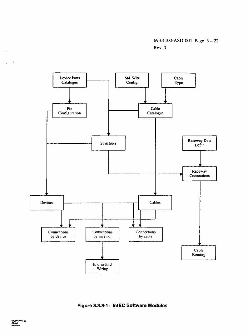
3.3.8 IntEC
IntEC is an AECL-developed program used to computerize via an interactivedatabase, a nuclear plant's cabling and wiring design and management tasks (see Figure 3.3.8-1).IntEC is currently in use in a 'stand-alone' mode on the Wolsong project. This description is forthe 'integrated IntEC' that represents the design intent of the software. IntEC is comprised ofthree databases. One database contains reference as well as cable specification, conductor andterminal configuration tables. These tables contain the data validation and design rules requiredby other IntEC applications. There is only one reference schema for a project. The IntECreference database also contains tables required by Intergraph's Electrical Engineer (EE) productline of software. The EE tables are customized to meet CANDU requirements for designingElementary Diagrams (ED's), Block Diagrams (BD's), Power Systems and Raceways. Thisschema is conventionally named eeref_<projno> ( note that for the purpose of data integration,the equivalent PDS database must be named re_cx, where ex is the project name). A secondschema category contains the device catalogue information, the structures data and all thenetwork file management data required by Intergraph's Network File Manager (NFM) ascustomized by AECL for managing CANDU design files. The devices and structures tables arerequired by IntEC only, although the NFM tables are not essential, they provide attractiveadditional capabilities when used in conjunction with the NFM software. This schema alsocontains tables to accommodate PDM/PDU adapted by AECL for the design of CANDU controlpanels and instrument racks. This schema is conventionally named npdm_<projno>. The thirdand final schema contains the electrical project design data which includes all the cabling andwiring data. Conventionally, this schema is called eee_<projno>. In 'integrated' IntEC thisschema will also contain EE tables, customized by AECL per CANDU needs (they must benamed ee_cx to allow integration with other PDS modules).
IntEC contains all the cabling, wiring and support data required to construct,commission and operate a plant.
a. System Configuration
- Hardware
• at least one UNIX node support by Informix (SUN, Intel running SCO UNIX,Intergraph) to act as Database Server
• any combinations of alphanumeric terminals, X-window Terminals (at least one),PCs, or UNIX W/S
- Software
• Informix on-line engine
• Informix SQL
• Informix 4GL
• Microstation (X-windows, SUN, Intergraph W/S)
• TCP/IP com protocol
• VT22O Emulation S/W for PC
W2O91/»7O-t949-asd9*111/02
69-01100-ASD-001 Page 3 - 2 2
Rev. 0
Device PartsCatalogue
PinConfiguration
Std. WireConfig.
CableCatalogue
StructuresRaceway Data
Defn
RacewayConnections
Devices Cables
Connectionsby device
Connectionsby wire no.
Connectionsby cable
End-to-EndWiring
Figure 3.3.8-1: IntEC Software Modules
94M»l/97(>-c9W-asd94/11X12
69-01100-ASD-001 Page 3 - 2 3
Rev. 0
b. Standard Objects Definition
Standard objects are used to define standard or generic information which can later used byother tasks to perform their intended functions.
Standard objects are divided into two types:
- cables and conductors
- device specifications and device terminal configurations
1. Cable and Conductor Specifications
Cable Specification information is organized in two main entities: CABLE TYPE andCABLE CATALOGUE. The standard cable specification objects are:
- single wires,
- control cables,
- power cables,
- overhead lines,
- standard cable assemblies (a future capability).
Cable type definitions include non-manufacturer specific information such asconductor/wire size, associated signal types, technical specification number and somebasic Environmental Qualification information. The Cable Catalogue contains most ofthe data required to fully define a cable catalogue item including all relevantmanufacturer data. Every entry corresponds to a Stock Code Number (SCN) uniquelyidentified by a part number. Several cable items can be associated with one cable type.All multi conductor items in the cable catalogue are associated with a set of conductorseither per standard colour codes or by special conductor configurations. Conductorassociations (such as conductor pairs, shielded sets, binders) can be defined during aconductor configuration session.
2. Device Specification and Device Terminal Configuration
Catalogue information about electrical device items is recorded in the DEVICES table.Every entry corresponds to an SCN item uniquely identified by a part number.Information stored in this entity includes general electrical attribute data, manufacturerdata, normal and abnormal ambient (test) data, EQ (test) data. Information about all thedrawings associated with every catalogue item can be recorded in the DRAWING table,if optional NFM file management software is used. Terminals can be configured forevery part in the devices table. The terminal information created includes terminal ID,function performed, single or double sided and number of connections allowed per side.
3. Cable Assemblies
A future capability will permit the ability to set up standard cable assemblies that can beused as templates when creating wiring information.
94/11/1)2
69-01100-ASD-001 Page 3 -24
Rev. 0
c. Structures Management
A 'structures' entity has been defined to record information about every free standingequipment in the plant. IntEC expects all wired devices to be located on a structure locatedin this entity. The software also expects all cables to be associated with a pair of structures.Some raceways (such as conduits) may also be connected to specified structures. Theinformation stored in the Structures entity includes equipment tag ID, part number, locationin the plant, normal and abnormal ambient data and Environmental Qualification (EQ)conditions data. Information about all drawings associated with every structure can berecorded in the drawing table if the NFM file management software is used.
d. Raceway Data Management
The Raceway Data Management application sets up the raceway design information used bythe Cable Routing processor. The two basic operations handled by the application allow auser to first, describe every raceway component, and second to interconnect the racewaycomponents, thus producing a nodal model of the plant raceway system.
1. Raceway Data Definition
Here a user enters information about every raceway component in the plant. Theattributes about raceway components include tag ID, type, part number, length, traywidth, conduit diameter, tray partitions widths, channel, signal type (voltage), cableinstallation requirement (maintained or random) and installation status. An automaticnumbering scheme creates default tags every time a new raceway is added. Thenumbering scheme is based on a number of criteria set up in the Raceway Numbers table.
2. Raceway Network Definition
This permits a user to create, or update the plant raceway network information requiredby the cable routing programmes. Raceway-to-raceway and structure-to-racewayconnectivity data is generated based on design rules stored in IntEC. Rule checks includeverification that only raceways of compatible channels and compatible signal types areinterconnected.
e. Cable Management
Through the cable management application, a user can assign new cables, maintain dataabout every cable in the plant, create valid routes for all cable paths in the plant, associatecables to valid routes and extract cable demand data for use in a project materialmanagement system, such as CMMS.
1. Cable Assignment
An automatic numbering scheme creates default cable tags every time a new cable isadded. The numbering scheme is based on criteria set up in the cable numbering table.Default cable numbers may be overridden by a user, but the software will check to ensurethat the new number is unique and meets all the rules defined for cable numbers.
69-Md94/11/1)2
69-01100-ASD-001 Page 3 -25
Rev. 0
2. Cable Definition
IntEC maintains data about every cable in the plant. The information includes "to" and"from" structures, channel, signal type, part number (relates it to all the cablespecification information in the cable catalogue and cable type tables), installationinformation and status information. For power cables, additional capabilities areprovided to relate these to their related feeder data. When adding new cables, conductorrecords are automatically created using the conductor configurations defined for everycable catalogue item.
Cable Routing Cable routing has two main tasks:
- Cable routing Manipulations, allow a user to Create new routes, Delete and Reverseexisting routes. The work is done interactively using the Raceway Networkconductivities established through Raceway Management. Route length and percentfills are automatically established by the software.
- Interactive route assignment allows a user to interactively assign to a specific cable,one of the valid routes established using the Cable Routes Manipulation programmes.The route length is used to determine automatically, a default cutting allowance value(based on data defined in a rule table) which can be overwritten by the user. A userwill be able to make the decision based on information which includes tray fill, trayloading and cable length.
f. Material Demand
The route length and the cutting allowance provide the cable length required for every cablein the plant. This data, in conjunction with the cable reel information available from thecable catalogue, can be used to estimate the number of reels required for every cablecatalogue item. This information can be passed to a project material management system,such as CMMS.
g. Devices Management
The Devices Management application generates and maintains data about all devicesrequired for electrical connections. Users are provided with the necessary screens required toadd new devices, modify data about existing devices, mark devices for deletion and purgedevices no longer needed. The application works in conjunction with the catalogueinformation in the devices table and with the terminal configuration tables, to automaticallygenerate the terminal ID required for wiring.
1. Device Definition
Device data includes device tag, channel, the tag of the structure on which the device ismounted, installation drawing, status, part number (through the part number, access isprovided to all catalogue data in the devices catalogue, device location within thestructure and wire grouping information.
69 isd94/11/02
69-01100-ASD-001 Page 3 - 2 6
Rev. 0
2. Terminal Definition
Further definition against each terminal includes channel, wire number, signal typeallowed, EQ required state, ED drawing and destination information for terminal strips.Data available by association with the standard terminal configuration includes numberof sides (one or two), number of allowed terminations per side, maximum wire size,terminal function (e.g. NO, NC, COIL).
h. Wiring Design Applications
IntEC delivers three wiring design applications:
- Structures (Panel) wiring,
- Cable Terminations,
- End-to-End Wiring.
1. Structures (Panel) Wiring
Structures Wiring provides the tools required to generate and maintain internal wiringassociated with panels, cabinets and instrument racks. Wiring information is createdbased on a number of rules which are accessed from standard terminal definitions. Therules include:
- maximum number of terminations per terminal side,
- minimum and maximum wire sizes allowed per terminal,
- signal type compatibility,
- channel compatibility,
- wire number matching including matching against external terminations,
- compatibility based on EQ requirements,
- wire colour versus channel and signal type matching.
Wiring data includes wire number, channel, signal type (usage or voltage), part number,colour and status information. A batch programme is run to verify circuit integrity andre-propagate wire numbers. In future, this utility will be extended to perform automaticwiring.
2. Cable Terminations
The cable termination application provides the screens for generating the connections in atrunk mode as well as on a single conductor mode. The functions and rule checksdescribed for structures wiring apply (with the exception of the wire colour versuschannel and signal type rule check).
3. End-to-End Wiring
The objective of end-to-end wiring is to confirm the integrity of electrical circuits and toprovide the means to complete and correct missing or erroneous information. A batchprogramme will be used to analyze the signals on a system basis.
94209I/970-C969-Md94/11 AC
69-01100-ASD-001 Page 3 -27
Rev. 0
3.4 MECHANICAL ENGINEERING
Pro/Engineer and EMS are currently being used in AECL for 3-D mechanicalmodelling.
3.4.1 Pro/Engineer
- Parametric feature-driven solid modelling.- Single parametric feature-driven database:
• PRO/AFD: advanced feature design Shell, Complex Domes, 3-D sweeps and complexblends.
• Pro/Detail: 2-D design.• Pro/Design: compile assemblies.• Pro/Draft: non parametric 2-D design.• Pro/Feature: user-defined features.• Pro/View: dynamically moving shaded design.
• Pro/Project: managements and coordination of multiple teams of designers.• Pro/Shellmesh: automatic mesh generation of FEM of thin-walled designs.• Pro/Tetmesh: automatic FE mesh generation.
Pro/Engineer is a recent addition to AECL's Software Design suite. Pro/Engineeris used in the mechanical discipline where a tight coupling of detail design, analysis andfabrication is required. Pro/Engineer is a parametric solids modeller with facilities forproduction of solid models, production of finite element meshes, a connection to commercialfinite element solvers (such as ANSYS), drawing production facilities and connection tonumerically controlled (NC) machines.
3.4.2 EMS
Intergraph's Engineering Modelling System (EMS) is similar in its capabilities toPro/Engineer. It is used in the mechanical discipline where a tight coupling of detail design,analysis and fabrication is required. EMS is a hybrid parametric and variational solids modellerwith facilities for production of solid models, production of finite element meshes, a connectionto commercial finite element solvers (such as ANSYS), drawing production facilities andconnection to numerically controlled (NC) machines.
3.4.3 PATRAN/ANSYS/STARDYNE for Stress Analysis
See description in Section 3.1.4.
3.5 INTER-DISCIPLINARY CAE TOOLS
Several of the tools used in computer-aided engineering are not specific to any ofthe engineering disciplines in the CANDU design. Rather, they are used in engineeringprocesses that span across discipline. These processes include material management,procurement, clashes (interferences) management, design review, and multi-discipline generalarrangement (GA) drawing production.
69-01100-ASD-001 Page 3 - 2 8
Rev. 0
3.5.1 PD_Clash for Clash Checking
This is a module of Intergraph's PDS software, used for the detection andmanagement of clashes in the 3-D model of the plant.
The clash detection software produces one picture per clash, showing the twoclashing items, their location in the plant, the type of clash ('soft' for envelopes and insulation,'hard' for hard physical items), and the model files which contain them.
The clash management software allows the review of the clashes on the screens ofthe work-station, in 3-D, for the approval and/or commenting of the clashes for action (whomoves). A unique clash number is assigned to each clash for tacking through the design process.This number is not re-used even if the clash is approved or resolved. Clashes are approved aspenetrations, or as false clashes (usually stemming from simplified modelling).
A separate clash pre-processor prepares the 3-D model files for a clash check,through processes called 'envelope creation' and 'envelope verification'.
3.5.2 Design Review and Model View for Model Walk-Through and Illustration
Design Review is Intergraph's software for review of 3-D models. It displays thecombined model files on a specially-equipped work-station with a large screen and ahigh-performance graphics card (Intergraph's Edge II). The display is in fully shadedperspective, with a capability of movement through the model. "Walking" along three globalaxes and three local axes is possible, as well as rotation of the viewer's virtual head about theseaxes. In the "encircle" mode, an object of interest is brought to the centre of the view, and thenviewed from all sides.
It should be noted though, that a walk through a large model (e.g. a full model ofthe Reactor Building), is not smooth, and it requires, during the motion, the employment ofspecial techniques for the prioritized display of objects of interest.
The reviewer can point at objects in the model and view text information aboutthem, such as piping line number, pressure, tray system number, and item tags. Groups of itemscan be turned on or off, or re-coloured for clarity, or moved and rotated for "what-if' analysis.The reviewer can measure distances in the model as well.
During the review sessions the reviewer can place comments in a special tag file,which can be recalled by other reviewers, or sent back to the designer a actions for modelrevision.
Periodically, the Design Review Integrator software collects selected informationfrom the databases and then loads it, together with the models' graphics, into the Design Reviewwork-station, for up-to-date walk-through sessions. This is necessary, since the Design Reviewsoftware operates in a stand-alone mode, without direct access to the Project database andgraphics.
The Model View software is used for the creation of photo-realistic pictures of the3-D model using the ray-tracing technique, including cast shadows, reflections and refractions,and material assignment. The software is capable of fixing and improving the resulting pictures,and it allows their annotation.
69-i.id94/11/02
69-01100-ASD-001 Page 3 - 2 9
Rev. 0
3.5.3 PD_Draw for the Extraction of Orthogonal Drawings
PD_Draw, a part of the PDS software, is used for creation of drawings, includingplans elevations and sections. It allows the designer to define drawings in the Project database,including the boundaries of the drawing's volumes (rectangular boxes "carved" out of the Plant,which are projected onto the drawing sheet), the view orientation and scale, as well as the modelfiles and item categories that are to be shown.
The selection of files by disciplines, allows the creation of drawings for Process(piping, equipment, and HVAC arrangement drawings), and for ICE (tray arrangements,instrument location).
The software performs hidden-line removal to convert the view from anincomprehensible wire-frame into a standard line-drawing.
The software allows the semi-automatic annotation of the drawing, i.e., thedraftsperson points at items in the drawing, and the software retrieves their labels from thedatabase and allows the draftsperson to place them in the drawing.
3.5.4 CANDU Material Management System (CMMS)
This system has been developed by AECL for the management of constructionmaterials of CANDU Projects. A detailed description of CMMS is given in Appendix E.
The material demand is entered into the CMMS system as Bills of Material. Inaddition, other aspects of the design such as designation of equipment codes, tabulation ofinstrument lists, and specification of material delivery schedules may be entered, as they are onWolsong 2, 3 & 4. From this information the engineer develops EQR's based on selectioncriteria and extracts material quantities and delivery requirements automatically. Materialdescriptions and technical references are retained in a material catalogue.
The EQR's so generated become the base for the production of the material listportions of requests for tender (RFT's) and for purchase orders (PO's) through the CMMSsystem. CMMS also provides the capability of generating site construction work packages andfor managing site inventory. Delivery schedules may be monitored within the system, allowingfull verification of material status from the point of engineering specification to delivery to siteand to the installation of the material during construction.
Since some of the CANDU design is not done within AECL, not all the materialis entered into the system. Structural steel, for example, is handled outside CMMS and outsideAECL.
AECL intends to establish a link between the 3-D models and CMMS so that thedemand is created automatically. CMMS will also be expanded for the use of all disciplines.
94209 l/»7»-c969-aid94/1 1/03
69-01100-ASD-001 Page 4 - 1
Rev. 0
4. ENGINEERING TASKS AND WORK PROCESS WITH CAE
This section describes how the Computer-Aided Engineering tools, listed inSection 3, are used for the design and construction of a large CANDU plant. Figure 4.0-1 is atime-chart of a plant life cycle highlighting the Computer-Aided Engineering (CAE) tasks withinan integrated plant information system.
The design activities shown on the chart are discussed here in detail, including thescope of the activity, the method of its execution, the hardware and software in use, as well asthe definition of responsibilities of the staff assigned to the activity. The other aspects of anintegrated plant information system (computer-aided plant construction, commissioning,operations and maintenance) are planned as future additions to the system. All futuredevelopment is discussed elsewhere in this document (see Section 5).
A design project is an iterative procedure which builds on preceding projects todetermine a satisfactory solution for its customer. There are typically five steps in each project:
- Conceptual design including feasibility studies, cost estimates, general layouts andpreliminary process flowsheets.
- Project setup of, from a software viewpoint, 2-D and 3-D design files, project files andstandards as defined in Reference Databases.
- Detailed design including design of processes, control and instrumentation, piping layoutsand analysis, equipment and instrument definition, material control.
- Design review including peer reviews and 3-D model walk-through.
- Production of documents for procurement and construction.
At each step of a project, CAE software provides assistance in standardizingequipment and material, in control loop design, in equipment layout, and in system design. Eachstep is an iterative process to optimize conflicting needs of cost, reliability and operability.
4.1 PRE-ENGINEERING
Engineering prepares preliminary sketches of the following items: process flowdiagrams, major equipment layout (all disciplines), plant space studies, major civil structureslayout, fabrication modules split, a split of non-modular portions into design volumes, andestablishes plant coordinate systems. These are MicroStation sketches, which are usually basedon existing CANDU designs.
Rough estimates of quantities of structural members, piping, equipment,instruments, raceways, ducts, and cabling are established.
Based on the figures collected, the CAE Project Coordinator (CAEPC) assessesneeds for hardware, software, personnel and training.
4.2 PROJECT-SPECIFIC PLANNING AND STAFF IDENTIFICATION
The CAE Project Coordinator writes a document titled Project Execution Plan,which is based on information from this document 69-01100-ASD-OOl, with specific detailspertaining to the Project.
942O9I/97O-C969-ud94/11X12
69-01100-ASD-001 Page 4 - 2
Rev. 0
The CAE Project Coordinator writes a second document titled Project DataConfiguration, which is based on the Company CADDS standards and document74-0113O-MAN-OO3 for Saskatoon projects. The Configuration document describes directoriesstructure and file/model naming conventions. A decision is made at this point about Size Rangesof physical objects in the 3-D model. The 3-D model is partitioned into files sets, each of whichcontain items of only one Size Range, i.e., large items (size A) in one set of files, medium items(size B) in one set of files, etc. (see also Section 4.3.2). This is to allow clash checking of largeitems first, then medium items, etc. Model file boundaries are usually at fabrication-moduleboundaries, so that the design can be frozen for each module independent of the others.
CAE Applications support staff are identified specifically for the Project, withone person responsible for software trouble handling and liaison with Intergraph Applicationsupport staff.
CAE Network support staff are identified specifically for the Project, with oneperson responsible for software trouble handling and liaison with Intergraph System, Network,and Plotting support staff.
Project Champion Users are nominated for each modelling/drafting softwarepackage.
Project Coordinators are nominated for: Clash and Layout Management (oneperson for the whole project), Orthogonal Drawings (one person for the whole project).Isometrics, Walk-through sessions, Piping Stress, Civil Stress, Cabling/Raceways, P&ID/Piping,Pipe Supports, Embedded Parts, CMMS (material management), and IntEC. These coordinatorsare needed mainly where CAE spans several disciplines or software packages, with automaticdata transfer occurring between them.
Training sessions begin, to update experienced staff on new CAE developmentsand to train new staff.
4.2.1 Progress Reporting
Progress reporting is based on manual reporting and supporting sketches plottedfrom the model. (Note: The existing 3DM process is to be reviewed and brought up-to-date tosuit current requirements.)
A typical piping line model progress report would be based on these completionstages:
Started 5%
Model input 50%
Model checked 60%
Model corrected 90%
Clash free 95%
A 5% contingency is left for unexpected revisions.
Progress on equipment modelling is measured by number of equipment itemscompleted.
942091/97(><969-asd94/11/02
69-01100-ASD-001 Page 4 - 3
Rev. 0
Progress for cable trays modelling is measured by number of tray runs, conduits,and supports completed.
Progress for extracted GA's is based on the amount of annotation completed.
Progress for piping isometrics is based on amount of set-up completed.
Progress for P&ID's is based on number of drawings which have been propagatedto 4OK' status.
Reporting method of progress for other schematics will be established, whenmore experience with the software is accumulated.
Progress reporting with regard to CMMS and IntEC have not yet beenestablished, although CMMS has some built-in features for progress reporting.
4.2.2 Coordination of CADDS Work
Co-ordination meetings are held on a regular basis to discuss activities regardingCAE. The CAE Applications Champion reports the status of outstanding logged problems, andplaces actions on the Disciplines representatives, on himself and on IT Network Operations.
Minutes are produced and circulated to the attendees, to Manager InformationTechnology, to Discipline Managers, and to the Project management.
4.3 PROJECT SET UP ON THE NETWORK
All file creation, deletions, and moves, are performed by CAE Applicationsupport staff, and not by the Users. This is to assure data integration between the differentdisciplines through the PDS Project Administration software.
Raw partitions are created on the servers' disks to hold Informix databases.
PDS Project "ex" is created in the same RIS schema file to assure integration ofthe disciplines, with the following Informix databases (ex is a general CANDU project number,x could be 6, 9, etc.):
pd_cx PDS project administrator
dd_cx Piping and Equipment data
ru_cx Unapproved piping reference data
ra_cx Approved piping reference data
ee_cx Raceways and EE_schematics project (design)
re_cx Raceways reference data
pid_cx P&ID task (and master) data
3-D Models are created in the project for all disciplines according to Size Rangesand Module (or System). Civil files are integrated into the project.
Schematics files are created.
W2091/97O-C969-asd
69-01100-ASD-001 Page 4 - 4
Rev. 0
Mechanical model files are created on EMS (or on Pro/Engineer).
Reference Databases are reviewed and adjusted for the specific Project needs asfollowing:
- Piping specs and vendors' catalogues are selected.
- Steel tables are selected for civil models, and for pipe support frames.
- Drawings and labels formats are selected.
- Raceways catalogues are selected.
- Cable management (IntEC) catalogues are selected.
- Mechanical design (EMS/Pro-Engineer) catalogues are selected.
- CMMS Catalogues are selected
A room is selected in the design office, and set up for Design Reviewwalk-through sessions.
4.3.1 Design Areas
A PDS design area is a rectangular volume bound by six coordinates (high andlow for each axis). Piping and equipment, which modelled by system (see 4.3.2 below), runthrough many areas, disregarding their boundaries. The selection of Area boundaries effectclash checking, as it is done in one area at a time. On the other hand, the Area boundaries haveno effect on GA's and isometrics, since it is possible to extract these documents across DesignArea boundaries.
In a modular CANDU project, each fabrication module resides in a separate area.In addition to the Module Areas, there are also Areas which hold hook-up spools andInter-Module models. For example, a PDS Area may be defined as following:
Easting
Northing
Elevation
Low
109800 E
87662 N
99412 El.
High
119000E
108350 N
115088 El.
4.3.2 Model 'By-System' versus 'By-Area', and Models 'By-Size-Range'
Piping is modelled by system, i.e., the piping in any given file spans a wholeprocess system. The advantages of this method are that there are fewer misalignment errorsbetween model files, and that a piping system isometric illustration can be produced easily.
Modelling by area would require that several systems are included in each modelfile, and that each file contain piping that belongs to a single fabrication module or design area.The main advantage of modelling by area is the ability to freeze the design of each module(write-protect the files) independently, and thus allowing independent issue of fabricationdrawings for each module at separate dates.
942O9l/97O-c969-asd
69-01100-ASD-001 Page 4 - 5
Rev. 0
The Size-Range concept, stipulates that large items are modelled in one set offiles, medium items in a second set of files, and small items in yet another set of files. Thisallows clash resolution and layout freeze for large item first, then medium items, etc. Otherwisethe layout cannot be frozen in stages, which causes difficulty in finalizing it.
Electrical raceways are modelled by area, with one file per module.
Civil files are organized by area, i.e., files contain models which do not spanfabrication modules or design areas.
The decision whether to use the size-range concept, and whether to model by areaor not depends on the construction schedule and on availability of layout information at projectstart.
4.3.3 Coordinate Systems
The coordinate system in use, is per project instruction 74-PI-413-B, where thecentre of the reactor building at grade elevation is at 100,000 mm in direction A, 100,000 mm indirection B, and at Elevation 100,000 mm. The letters A and B are used for plant north and eastrather then N and E, in keeping with the previous CANDU projects. However, the extracted GAdrawings and the piping isometrics have the letters E and N with the coordinates values, and anote on each drawing, stating that plant north coincides with direction A.
All column grid-lines are to be labelled with A(y) or B(x) coordinates in additionto the conventional bubbles, with letters on one axis and numbers on the other axis.
4.3.4 InteEC Project Setup
Databases are created and initial data loading starts. Electric cable catalogues andspecs are loaded, as well as conductor configuration, connect-point configuration, and devicepart catalogues.
4.3.5 CMMS Project Setup
A CANDU Material Management System database is set up on a server withAECL's standard Stock Code Numbers for the materials that are defined in the Project Standards,but with zero quantities in material demand and supply. The supplier directory and theappropriate portion of the material catalogue is copied from previous projects.
4.4 CIVIL ENGINEERING
4.4.1 Structural/Civil Modelling
Civil designers model the structures using ModelDraft. The 3-D model includelinear steel members, steel platforms and grating. Secondary steel, i.e., equipment support andsteel within concrete, will also be modelled.
Concrete walls and floors, including concrete poured into module steel(composite walls and floors), are fully modelled.
94/1 \IO2
69-01100-ASD-001 Page 4 - 6
Rev. 0
Fireproofing of steel members is modelled.
Gusset plates and stiffeners are not modeled precisely, but specially-identified area elements areplaced in the model to reserve space for the actual items.
Reserved space, such as for monorail hoist operation, are modelled and identifiedas such.
Architectural members (false ceilings, floors, partitions) are modelled with area orvolume elements, using ModelDraft.
Stairs and railings are modelled using ModelDraft so that they can be analyzedwith MicasPlus.
4.4.2 Model Verification and Propagation
The designers run the "Verify" command on a periodic basis, as well as beforemodel propagation, before drawing extraction and before stress analysis information extraction,or on request.
4.4.3 Steel Catalogues
The steel section table, containing a reduced set of sections for materialstandardization and special sections, are maintained by the ModelDraft Champion User.
Separate tables may exist for different fabrication modules if their construction isawarded to different fabricators.
4.4.4 Embedded Parts for Penetrations
The demand for embedded parts (EP) for penetrations is created via special clashruns, based on clashes of pipes and trays with walls and floors. Cable trays and pipes areinitially modelled so that they run through walls and floors. The PD_Clash software detectsthese "clashes", and the Clash Champion approves it as a penetration, the piping designers thenmark Field welds on the piping at the nearest weld, and a special "EP" component with near-zerolength is placed in the piping model (to create graphics on the isometrics). Once the design hasbeen frozen, gaps are modelled in the trays, where necessary. The embedded parts themselvesare modelled by Civil using ModelDraft. Another special clash run, which includes only pipingversus the EP model, serves as verification that there are no "orphan" EP's (with nothing passingthrough them). A final special clash run (special marker file), with piping versus concrete helpsverify that all required penetrations have an EP.
A PDS clash database report serves as an embedded sleeve penetrations list. Alink will be established with Civil's Embedded Part (EP) database and detail design package(under development in our Saskatoon office using EMS software), to transfer information into itfrom the PDS clash database.
Other embedded parts, such as support anchoring, will be added to the EPdatabase and detail design package, through other means.
69-01100-ASD-001 Page 4 - 7
Rev. 0
4.4.5 Steel GA Drawings
Steel layout drawings are extracted using MicasPlus Draw. Final drawings areextracted only after the design has been approved. Interim extractions are used only for modelchecks. The MicasPlus Champion User customizes the drawings' formats.
Detail drawings are drawn manually using MicroStation.
4.4.6 MTO for Steel and Concrete
Material take-off lists are extracted from the models. Both bills of materials andweight/centre-of-gravity reports are produced. The ModelDraft Champion User customizes thereports' formats.
The information is manually transferred to a material-management system (e.g.,CMMS) to create material demand.
4.4.7 Structural Stress Analysis and Design
Stress Analysis and steel structure design is performed on the ModelDraft modelby Civil, using MicasPlus, as well as ANSYS and STARDYNE to supplement the MicasPluscapability. The geometry, properties, loads, and restraints are extracted from the 3-D model viaMicasPlus. Rigid links may be required for steel members which do not frame into othermember-lines. Care should be taken not to let these rigid links to be read back into theModelDraft file.
The design is an iterative process by which information from the analysis/designpackage in MicasPlus gets back into the ModelDraft model. The model is verified andpropagated before releasing the changes to the other disciplines. Conversely, equipment loadson the MicasPlus model are changed as the layout is revised. These changes are trackedmanually, and require manual revision of the MicasPlus model.
Note: At present, only linear elements (columns, beams, braces) can be designed toCanadian Code with MicasPlus and with the following exception: Class 4(slender and unspecified per Canadian steel book 1991 p. 1-36) elements.Difficulties are being experienced in MicasPlus Design according to CanadianStandards, and in composite (concrete and steel plates) structures design. Thedesign for these problem-structures is done manually with ANSYS analysis andspecialized software developed in house.
4.4.8 Detail Design
Detail design of concrete (e.g., re-bars) and steel (e.g., joints) is not currentlyavailable within the integrated CAE software, and is done in a stand-alone mode.
69-asd94/11/02
69-01100-ASD-001 Page 4 - 8
Rev. 0
4.5 PROCESS ENGINEERING
4.5.1 P&ID, LL, EL, and VL
The Process Group draws P&ID's from preliminary sketches. Successfulpropagation to 'OK' status and posting, serves as data integrity assurance. The Process Designuses the P&ID's to transfer information into the 3-D piping model, to check the 3-D model andto produce line-lists, equipment-lists, and valve-lists.
4.5.2 Piping Modelling
Process designers construct the piping model using the PD_Design (piping)software and by the transfer of line information from P&ID. Models are completed and thenrevised for clash resolution, and component re-construction to accommodate RDB (spec)changes. The placement of pipe-to-tube adaptors in the piping files are done by ICE staff.
As a rule, all piping including $" instrumentation tubing is modelled. Theexception is field-run piping which is not stress-analyzed.
Construction tolerance allow for deflections resulting from pipe-whip andwater-hammer. The pipe movement envelopes is defined by Process Piping.
Underground (drainage etc.) piping are not modelled.
In-line instruments are modelled.
Vents and drains are modelled.
Equipment/vessel trim piping is modelled in separate file(s). The trim piping fileis excluded from MTO and fabrication iso's, but is included in clash checks.
Pipe supports is modelled as described in 4.5.8.
Many non-graphic data are read automatically and attached to graphic pipingitems. However, some data must be keyed in. Hence, the designer manually enters valve tags,instrument tags, and specialty item tags, or, if possible, transfer the information from P&ID.Other data such as line temperatures, pressures, and fluid density are transferred from P&ID.
4.5.3 Inter-Module Hook-up Spools
In a modular CANDU design, the hook-up piping spools will be welded aftermodule installation in the reactor building. All pipe spools in the 3-D model, leaving a givenmodule, to connect to modules of a higher number are modelled as hook-up, i.e., theconstruction status is set to 'module hook-up* up to the first weld outside the module in question.For example, the hook-up piping connecting RM20 to RMIO will belong to RMIO, whereas thehook-up piping connecting RM20 to RM30 will belong to RM20.
Correspondingly, the inter-module hook-up spools are identified on the pipingfabrication isometrics as such, with dashed graphics and a line break depicting the hook-upcomponents.
W2O9I/970-C969-udw/ii/o:
69-01100-ASD-001 Page 4 - 9
Rev. 0
4.5.4 Equipment Modelling
Modelling of all equipment is done using the PD_EQP software. Models ofequipment items should be simple, in order to avoid over-loading of the system during screenupdates, clash checks, walk-through, hidden-line removal, and to reduce disk space requirement.
All mechanical equipment is modelled, including process, fuel handling, andHVAC equipment.
Space is reserved for maintenance, access, safety, constructability.
4.5.5 HVAC Modelling
Heating, ventilation, and air-conditioning ducts have a circular cross-section andthey require stress analysis. They are therefore modelled using the piping software, which has alink to stress analysis software (e.g., ADLPIPE).
4.5.6 Piping/Equipment GA Drawings
Genera] arrangement drawings for Piping, Equipment, and support location areextracted using PDS_Draw. The number, location, scale and orientation of each drawing aredetermined by the Piping Design Champion. The drawings are annotated as necessary, bearingin mind that the piping fabrication/construction information is taken mainly from the iso's. Oncethe GA's are created and revisions to the 3-D models occur, the GA Extraction Championdetermines which drawings (GA's, iso's, etc.) require updating as a result of 3-D modelsrevisions.
4.5.7 Piping Reports
The principal reports include bill of materials and centre of gravity reports. Atemporary material coding system is devised for the project, and then a link is established withan external material management system, such as CMMS. The material management systemassigns stock code numbers to the listed components, and handles demand from the 3-D modelversus supply via EQR's.
4.5.8 Pipe Supports
Pipe supports are modelled by Process in two portions: one in the piping model,and one in a structural model. The first portion is done via PD_Design software, which producesgraphics in the shape of an "X" to define the location, and database entries to define the type ofthe support. The second portion, modelled with ModelDraft, defines the physical volume of thesupport, for clash detection. The physical model includes steel frames made from standardsections, and attachments such as springs, rods, snubbers. The attachments are modelled withsteel sections, such as round or square hollow sections. The physical model does not includesmall components such as bolts, clamps, and straps. Support detail drawings is produced usingIES/NPSR software combined with dumb MicroStation for graphics clean-up and annotation.Some supports are drawn entirely with dumb MicroStation. It should be noted that theIES/NPSR support design environment is currently not fully functional, and that the current pipesupport design process is documented in a separate design guide.
943O9I/V7O-C969-isd94/11/1)2
69-01100-ASD-001 Page 4 - 1 0
Rev. 0
A special steel catalogue, with a restricted choice of sections, is used for pipesupports frames to achieve material standardization. The catalogue may require the addition ofdummy-sections to represent such items as turnbuckles, rods, springs, and snubbers.
4.5.9 Piping Isometrics
The Isometrics Champion customizes the PD_Iso software and extracts isometricsfor piping. Process Engineering may need to make minor manual revisions to the iso's. Theseinclude pipe support attachments details, and title block corrections. The isometrics Championdetermines which isometrics are to be updated as a result of 3-D model revision.
4.5.10 Piping Stress Analysis
The data for analysis is extracted from the 3-D model using the PD_Stresssoftware and the PDS-PSA environment. Where necessary, the data is modified manually. Thestress analysis is performed using ADLPIPE. Revisions to the stress model (e.g., addition ofexpansion loops, relocation of supports, representation of flexible nozzles) are tracked manually.This means that the 3-D model requires manual revisions to reflect the stress-model revisions.There are several such cycles of analyze/revise.
4.5.11 Thermo-Hydro-Dynamic Analysis
Analyses such as water-hammer is not done on data from the 3-D model, as theextraction/analysis software is not ready for use.
Thermo-hydraulic analysis is done using NUCIRC, P-Tran and Ailing, describedin Section 3.2.8. None of these software packages is linked to the 3-D PDS models.
4.5.12 Piping Reference Database (RDB)
Throughout the engineering phase, the Piping Reference Database (RDB)Champion continues the maintenance of the Piping Material Classes (specs) and catalogueinformation as the design progresses. The RDB Champion will enter size-dependent commodityitem descriptions, instrument descriptions, specialty-item descriptions, and pipe-supportdescriptions to be used in bills of materials. The RDB Champion also adjust seed filesinformation (graphic standards), and label descriptions (e.g., DesignReview labels and drawingformats of item tags).
The RDB Champion is responsible for running the quality-assurance checks onthe RDB (table checks).
It is the responsibility of the RDB Champion to run the specialized software forflagging items which need revision as a result of RDB changes. It is also his/her responsibilityto advise the Piping Design CADDS Champion, so that the items can be re-constructed in themodel.
942091/1171 l-c969-isd9411 ma
69-01100-ASD-001 Page 4 - 1 1
Rev. 0
4.6 INSTRUMENTATION, CONTROL & ELECTRICAL ENGINEERING (ICE)
4.6.1 Electrical Raceways
Raceways are modelled with EE_Raceways software. Trays and conduits aremodelled by ICE according to the Conduit Guidelines in 74-57700-TS-001. Tray separation isvisually-assured by the designers, as there is no simple means of checking it by software. Themodel files are organized by module and by channel, and the trays are colour-coded by channel.
All cable trays are models. Conduits are modelled if they are not field-run,according to the judgement of the discipline engineer, and according to the Conduit Guidelinesin 74-57700-TS-001. Junction boxes and airways are modelled to maintain cables continuity forlinking up with IntEC, the cable management software.
4.6.2 Tray Catalogues
Tray catalogue information, such as materials, tray types, dimensions, and unitweight, are entered and maintained by the EE_Raceway Champion.
4.6.3 Tray Supports
Tray supports are modelled by ICE (may be done also by Civil), usingModelDraft. A special steel section table is created for these supports. The sections (profiles) inthe catalogue should be simplified to avoid over-loading of the system during screen updates,clash checks, walk-through, hidden-line removal, and to reduce disk space requirement.
4.6.4 Tray Support Stress Analysis
Tray support stress analysis and seismic qualification is not done integrally withinCAE. Any revision to the trays' layout and support is conveyed manually back to the modeller.
4.6.5 Tray Material Take-off
Tray and conduit MTO is done using EE_Raceway software. Both bill ofmaterial and weight reports are produced. Tray support material take-off is done usingModelDraft.
The material lists is manually transferred to a material management system (e.g.,CMMS) to create material demand.
4.6.6 Tubing Modelling
The ICE designers model tubing using the PD_Design, i.e., piping software. It isthe responsibility of ICE to place the pipe-to-tube adaptors in the Process piping files, and toassign to them the loop numbers. The Piping RDB Champion maintains tubing specs andcatalogues for ICE.
All instrumentation tubing V4" and above is modelled, with the exception offield-run tubing.
69-ivi94/11AK
69-01100-ASD-001 Page 4 - 1 2
Rev. 0
4.6.7 Tubing Supports
Tubing supports are quite different from pipe supports, as they are built fromspecial clamps and spacers that are not included in the EES/NPSR software. This software, usedfor the detail design and analysis and drawing production of pipe support, is therefore inadequatefor tube supports. The detail design of tubing supports is done manually.
4.6.8 Tubing Isometrics and BOM
Isometrics are extracted using ISOGEN. The iso Champion (Process) customizesthe software for ICE needs.
AS with process piping. Bills of Materials are extracted from tubing models viaPD_Report. The BOM is fed into material management system (CMMS) to create the materialdemand.
4.6.9 Tubing Stress Analysis
As in process piping, the data for analysis is extracted from the 3-D model usingthe PD_Stress software and the PDS-PSA environment. Where necessary, the data is modifiedmanually. The stress analysis is performed using ADLPIPE. Revisions to the stress model (e.g.,addition of expansion loops, relocation of supports) are tracked manually. This means that the3-D model requires manual revisions to reflect the stress-model revisions. There are severalsuch cycles of analyze/revise.
4.6.10 Electrical Panels, Instruments Racks and Lighting Fixtures
ICE designers model panels, racks, and lighting fixtures, using PDS equipmentmodelling for the purpose of clash checking.
The Mechanical Design group produces a detailed model of racks and panels,outside PDS, using EMS (or Pro/Engineer) software, for the purpose of stress analysis anddetailed fabrication drawings production (see Appendix D).
4.6.11 Electrical GA Drawings
General arrangement drawings for raceways, electrical equipment, and in-lineinstrumentation are extracted and annotated, using the PDS PD_Draw software. The ICEDiscipline determines which drawings require to be updated as a result from 3-D modelrevisions.
4.6.12 Instrument Loop Diagrams
ICE designer produce ILD's using P&ID software. The work method is describedin detail in Section 3.3.5. Updating of P&ID reference data (RDB) is the responsibility of the2-D RDB manager.
4.6.13 One-line Diagrams and Electrical Analysis
One-line diagrams are drawn manually, until a software product is found which isbetter than EE_power.
94/11A»
69-01100-ASD-001 Page 4 - 1 3
Rev. 0
4.6.14 Elementary Diagrams
ED's are produced using the EE_Schematic software. Updating of the relatedreference data (RDB) is the responsibility of the 2-D RDB manager.
4.6.15 Cable Block Diagrams
Block diagrams are produced using the EE_WPD software. Updating of therelated reference data (RDB) is the responsibility of the 2-D RDB manager.
4.6.16 Cabling and Wiring Reports
Cable reports (by i.d, by route, etc.), and cable pull sheets as well as demandcable reports are created via IntEC software.
Wire connection reports (by device, by cable, end-to-end, etc.), are generated viaIntEC software.
Quality assurance tools within IntEC are used for design checks, such as unclosedcircuits, and cable relations with no valid routes.
Cable tray loading reports, content reports, etc. are extracted via IntEC.
4.6.17 Electrical Structures and Devices Reports
Reports listing electrical structures such as panels and racks are extracted viaIntEC.
Reports listing electrical devices are extracted via IntEC. Two types of reportsexist: a summary report and a detail report.
4.7 MECHANICAL AND FUEL HANDLING ENGINEERING
Mechanical design is done on EMS (or on Pro Engineer). A 3-D model of themechanical components is constructed for interference checking, tolerance, stress analysis, forthe production of fabrication drawings, and for NC machining of parts.
4.7.1 Clash Checking of Mechanical Items
The EMS models are clash-detectable only within EMS. To check interferencedwith other disciplines the EMS model is converted to a microstation envelope to reserve spacefor the fuel handling machine and other large mechanical equipment.
4.7.2 Mechanical Drawings and BOM
Fabrication drawings and bills of materials are extracted from the EMS model.
4.7.3 Stress Analysis for Mechanical Items
Geometry data are extracted from the EMS model, and then transferred toPATRAN or to ANSYS as input for the analysis.
94209 l/97(Vt969-asd94/1IAC
69-01100-ASD-001 Page 4 - 1 4
Rev. 0
4.7.4 Interface With N.C.
A numerically-controlled machine code is created from the model for directfabrication. This has been tested in AECL's SPEL.
4.8 CLASH MANAGEMENT
The Clash Champion schedules and executed clash checking and management.The discipline designers revise the models to eliminate clashes. The co-ordination of clashelimination (who moves) is done by the clash Champion.
4.8.1 Clash/Freeze Cycle
Each Design Area and each Size-Range within it goes through several cycles ofmodel->clash->resolve until the Area is clash-free and ready to be frozen. See Figure 4.8.1-1.
Once frozen, that portion of the model is locked so that no change is possible,unless special approval is granted. Model freezing is possible for Civil and Raceways, but notfor Piping/tubing and Equipment, since the latter are modelled by system and not by area.
Clash runs are run at Project milestones and as required by the Project Manager.Additional interim clash runs will be performed without issuing pictures. This serves also asprogress reporting on clash resolution.
The Clash Champion reviews the clashes on the screen, approves the falseclashes, plots the real clashes, and mark those judged a penetration with "PENETRATIONREQUIRED". The clash pictures are then distributed to the disciplines involved. In a firstclash-review meeting. Discipline representatives and the Clash Champion review the clashes andassign initial actions (e.g., model revision, set up one-on-one meetings between Disciplines). Ina second clash-review meeting, final actions are assigned (i.e., acceptance or removal of clash).
A second clash run then takes place, followed by the Clash Campion's screenreview and plotting. The third and last clash-review meeting results in actions for the resolutionof all remaining clashes. The third clash run must result in zero active clashes.
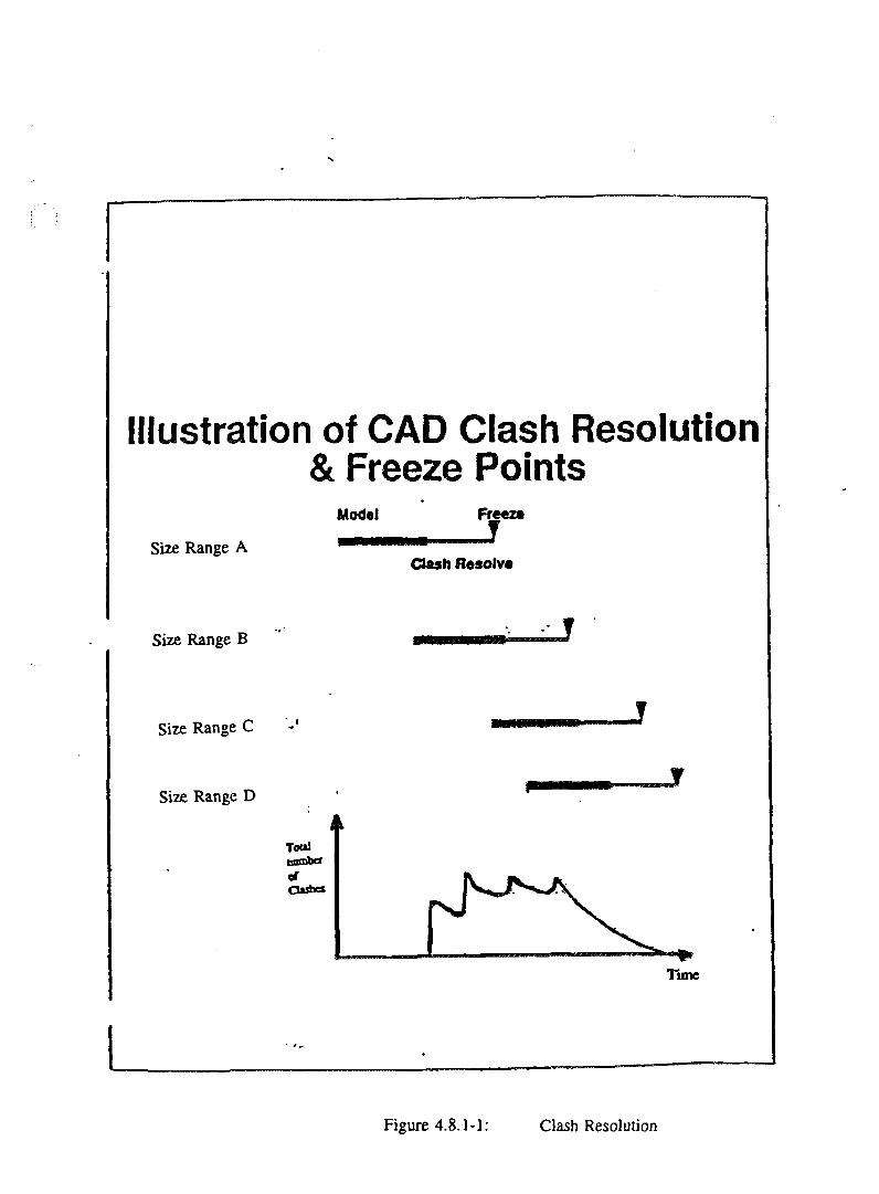
Illustration of CAD Clash Resolution
Size Range A
Size Range B
Size Range C
Size Range D
& Freeze PointsModel Freeze
Clash fteaolv*
, »
f
iTooltmmbcf
ClashesIV it . *
lime
Figure 4.8.1-1: Clash Resolution
69-01100-ASD-001 Page 4 - 1 6
Rev. 0
4.8.2 Clash Envelopes for Deflection/Deformation
Deflection of pipes and trays resulting from occasional loads (e.g., seismic) maycause clashes during plant operation. A special envelope model for trays (EE_Raceway orequipment modelling), and a special piping model with mock-insulation are used during aspecial clash run for the detection of deflection/deformation clashes.
Other special models are built, which take into account material creep, andcold-springing of pipes.
All special models do not take part in the usual clash checking.
4.9 WALK-THROUGH AND DESIGN REVIEW
The DesignReview software (see 3.5.2) is used for walking through the model forthe purpose of design review. A special review room is required, with large a viewing screenand an overhead/slide projector.
In preparation for the review session, the PD_Review integrator is run, to updatethe data on the DesignReview station.
Staff representing different disciplines, the constructors/fabricators, and theProject's client, meet to review the model periodically, for discussions about constructability,construction sequence, accessibility for maintenance and operation, safety, location of lighting,location of fire-fighting equipment and fireproofing, location of communication equipment andcameras, complex clash resolution, etc.
The problem-items is tagged, and a screen hard copy is produced for the minutesof meeting.
4.10 PICTURES FOR MARKETING AND ILLUSTRATIONS
Photo-realistic pictures of the CANDU plant, or of its details are produced usingthe ModelView software see (3.5.2). The pictures annotated with ModelView as well and thenthey are printed on the Marketing colour printer, with an option of producing slides forover-head projection. The graphic files are sent out for the production of 35 mm slides.
4.11 MATERIAL MANAGEMENT
Project material demand, procurement and tracking is done through the use ofCANDU Material Management System (CMMS), combined with traditional manual methods.In W-2 Project the demand and supply and the monitoring of consistency between the two isdone in CMMS. The tender and purchasing is done in manual methods based on data fromCMMS. Future projects will implement all the features of CMMS to completely automatematerial management.
4.11.1 Material Demand and BM's
Material demand is created through the manual entry of bills of material into theCANDU Material Management System (CMMS). As an alternative, estimates based onprevious projects may be entered as a reference baseline. This baseline may be useful whenprocurement must be started before the design can be adequately defined.
69-asd94/1 M)2
69-01100-ASD-001 Page 4 - 1 7
Rev. 0
An accurate demand is created as the 3-D models approach completion and thebills of material generated from them are entered into CMMS. Presently the entry of these billsinto CMMS is done manually but, as mentioned previously, one of the software developmentobjectives is to make this process automatic.
At the same time as the bills of material are entered system delivery dates basedon construction target dates may be entered into CMMS. This allows material procurement toproceed on a time-line which is compatible with the construction schedule and provides earlywarning if there is a danger that the schedule will be impacted by late deliveries.
Demand for all materials is generated through CMMS. It is expected that in thefuture demand for wire and cable will be defined by IntEC.
To ensure data accuracy the only bills of material which are acceptable on theproject are those generated through CMMS.
Cabling and Wiring demand is generated through the IntEC environment.
4.11.2 Material Supply and EQR's
The material list portion of EQR's is generated through CMMS. Additionaltechnical descriptions and supporting documentation are identified and supplied by theresponsible procurement engineer. In the future CMMS will be extended to include theautomatic identification of supporting documentation (specifications and drawings).
The material list portions of requests for tender and purchase orders as generatedby CMMS are not presently being used directly because of deficiencies in the descriptions of thematerial as inherited from previous projects. They are however used within AECL as controllingdocuments.
4.12 NETWORK OPERATIONS
The Network Operations group is responsible for the following activities anditems:
- Functionality of the hardware, i.e., workstations/server, network, printers and plotters.
- Loading new software deliveries.
- Supply of manuals and users' guides from Intergraph and others.
- Ensuring the standardization of software set-up among all work-stations.
- Software support for Nucleus products including UNIX, NFS, IPLOT and Informix. TheNetwork Operations group logs problems with Intergraph for these software items, andfollow-up on the problem resolution.
- System security, users log-in control, and passwords.
- Backups, including special PDS backup, known as Project Archival.
- Plotting and printing functionality.
- Software development for utilities specified by the CAE Project Coordinator.
942091/V7O-C969ud94/1 i/u:

69-01100-ASD-001 Page 4 - 1 8
Rev. 0
4.13 SOFTWARE/HARDWARE VENDOR SUPPORT
Intergraph supplies support for problems which have been logged by CADDSSupport.
It is the responsibility of CADDS Applications Champion to verify thatIntergraph carry out theses activities to completion.
Intergraph will train project staff in some of the new software features andsoftware packages.
942OTI/970-C969-ml94/1 I/TO
69-01100-ASD-001 Page 5 - 1
Rev. 0
5. FUTURE DEVELOPMENT AND RECOMMENDATIONS
The development in plant information systems in the foreseeable future can begrouped in three categories:
- Use of newer computer technologies, such as new hardware and new software architecture(Section 5.1).
- Enhancement of existing computer-aided engineering software for Plant design andconstruction (Section 5.4).
- Expansion and integration of software to include other stages in the life-cycle of the CANDUplant, such as maintenance, and operation (Sections 5.2 and 5.3).
5.1 NEW HARDWARE AND OPERATING SYSTEM: INTEL/WINDOWS NT
Intergraph have started to implement their decision to develop a new hardwareplatform for the PDS software. They have ported the P&ID, PD_EQP, PD_Design, PE_HVAC,and DesignReview to their Intel-based personal work-station. Named TD4 and TD5, thesework-stations are based on a dual Pentuim central processing unit from Intel Co., and are usingthe Windows NT operating system.
Although Intergraph is assuring their clients that they will continue to support thecurrent CLIX version of PDS, it is almost certain that the computer-aided plant design industrywill move, within a year or two, to the more-wide-spread Intel/Windows environment. AECLshould not lag behind in phasing in the new environment. The transition can be a smooth one,due to the fact that both environments can operate in tandem on the same network.
A problem exists with MicasPlus, which Intergraph says they will not port to theIntel/Windows environment, due to the scarcity of users of MicasPlus Analysis/Design. Instead,Intergraph has introduced the simpler Frame Works software. Frame Works is capable of 3-Dstructural modelling and steel drawings extraction, with a link to stress analysis software(STAADS). But it has no concrete modelling capability.
The recommendation is to start transition into the Intel/Windows platform but tokeep some CLIX work-stations and continue to use MicasPlus for the next two years. Softwaredevelopment for MicasPlus should take into account future portability to the Intel/Windowsplatform.
5.2 PLANT CONSTRUCTION AND COMMISSIONING
During plant construction, the value of making use of the wealth of CAE dataaccumulated during the design phase, is indisputable. Although plant construction managementsoftware does exist, we are not aware of existing links between it and CAE data.
5.2.1 Walk-through, Drawings and Progress Monitoring
DesignReview walk-through sessions with the construction team help clarifycomplex layout, and the tagging capability of the software can be helpful in tracking ofcomponents installation and commissioning for progress monitoring.
69-aid94/11X12
69-01100-ASD-001 Page 5 - 2
Rev. 0
Construction drawings and reports can be extracted by the constructorsthemselves, either to supplement issued documents, or as the only means of deliveringconstruction information from the designer to the constructor.
It is recommended to develop the methodology of making use of the models anddatabases during the construction and commissioning of a CANDU plant.
5.2.2 Construction Simulation
Software packages exist on the market which allow the use of the 3-D Plantmodel during construction. The Construction Simulation Toolkit software by JacubusTechnology allows the planners to see a simulation of the plant construction on the screen in3-D, driven by the construction schedule. Revisions to the schedule are reflected immediately inthe simulation.
Other software allows the interactive move of individual objects in the 3-Dmodel, as well as dynamic clash detection (Walkthrough PC by Jacubus).
It is not recommended to rely on these software packages only. They should beevaluated along with other similar packages, with attention to possibilities of linking with ourexisting CAE tools.
5.2.3 Computer-Aided Manufacturing (CAM)
The use of CAM is well developed in the aircraft industry and in the car industry.Although nuclear power plant are not manufactured on a production line, there are plantcomponents that are produced in a repetitive process. The geometry of these components,digitized through the use of our existing software packages, can probably be fed into thefabrication systems. The following processes should be investigated for numerically controlled(NC) fabrication:
- NC machining of parts (e.g., end-fittings), based on output from EMS or Pro/Engineersoftware.
- NC linear steel and plates cutting, based on output from a steel detailing packagedownstream of MicasPlus.
- NC pipe cutting, based on output from PD_Design and ISOGEN.
- NC pipe bending in conventional bending machines and in induction bending machines,based on output from PD_Design and ISOGEN.
- NC pipe/tube welding based on output from PD_Design and ISOGEN.
5.3 PLANT OPERATION, MAINTENANCE, ADMINISTRATION ANDDECOMMISSIONING
Software packages for the management of power plants exist in the industry, asthe examples in Appendix C demonstrate (Mitsubishi's NUWINGS and EDF's PHENIX).AECL's CMMS has the capability to monitor site material inventory. However, the availablechoices, with links to AECL's existing CAE tools, are limited.
69-ud94/11/112
69-01100-ASD-001 Page 5 - 3
Rev. 0
Intergraph's PDME, described in the following paragraphs, should be consideredas a candidate for CANDU Plant management software.
PDME - Plant Data Management Environment software was originally developedby Intergraph to help store, retrieve, revise, index, query, audit and distribute plant documents.The software has been extended to include the tracking of plant items like equipment,instruments and piping, with regard to plant modifications, inspections, maintenance andoperation, together with the associated drawings, change-requests and work-orders.
The linking of PDME with PDS is now under development in Intergraph with aforecast release in next year.
Figure 5.3-1 shows how data are transferred between PDS models and othermodels on one side, to walk-through software and PDME on the other side. The top portion ofthe figure relates to capturing data from existing plants using stereo-photography, and theirconversion into 3-D models.
W3O91/97O-C969-ud94/tl/TC
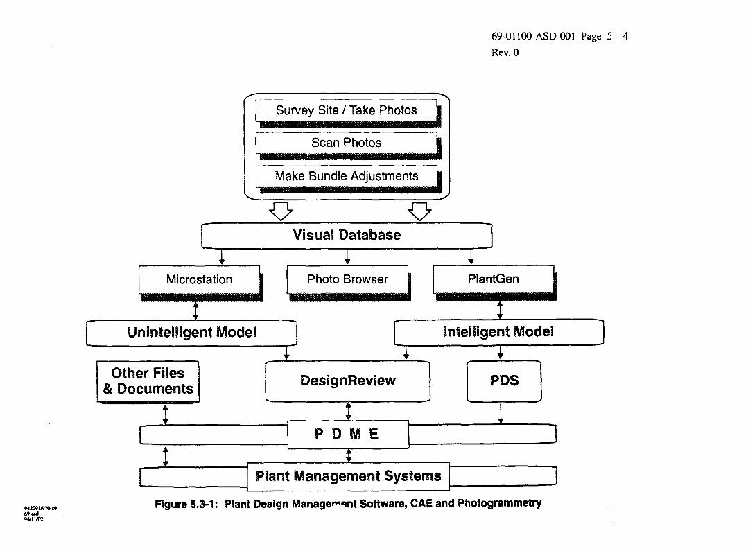
69-01100-ASD-001 Page 5 - 4
Rev. 0
Microstation
Unintelligent Model
Other Files& Documents
Survey Site / Take Photos
Scan Photos
Make Bundle Adjustments
Visua3 Database
Photo Browser
DesigrsReview
PlantGen
Intelligent Model
Plant Management Systems
MX* 1/970*969 ud
Figure 5.3-1: Plant Design Manage»~«»nt Software, CAE and Photogrammetry
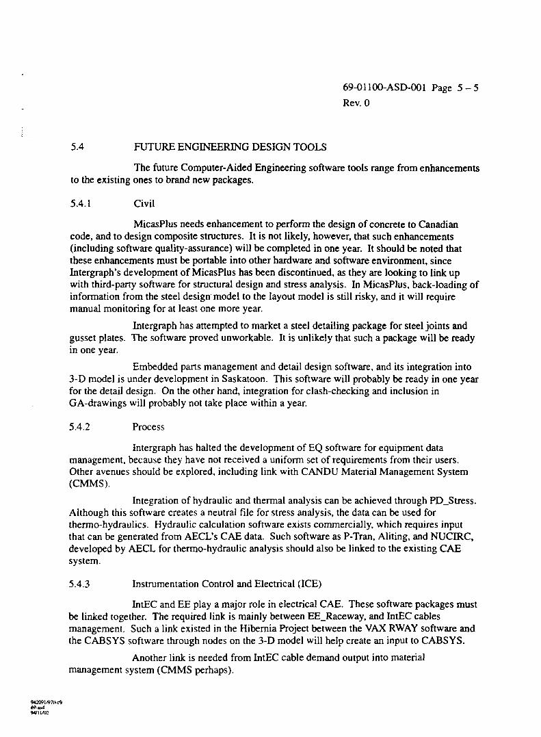
69-01100-ASD-001 Page 5 - 5
Rev. 0
5.4 FUTURE ENGINEERING DESIGN TOOLS
The future Computer-Aided Engineering software tools range from enhancementsto the existing ones to brand new packages.
5.4.1 Civil
MicasPlus needs enhancement to perform the design of concrete to Canadiancode, and to design composite structures. It is not likely, however, that such enhancements(including software quality-assurance) will be completed in one year. It should be noted thatthese enhancements must be portable into other hardware and software environment, sinceIntergraph's development of MicasPlus has been discontinued, as they are looking to link upwith third-party software for structural design and stress analysis. In MicasPlus, back-loading ofinformation from the steel design model to the layout model is still risky, and it will requiremanual monitoring for at least one more year.
Intergraph has attempted to market a steel detailing package for steel joints andgusset plates. The software proved unworkable. It is unlikely that such a package will be readyin one year.
Embedded parts management and detail design software, and its integration into3-D model is under development in Saskatoon. This software will probably be ready in one yearfor the detail design. On the other hand, integration for clash-checking and inclusion inGA-drawings will probably not take place within a year.
5.4.2 Process
Intergraph has halted the development of EQ software for equipment datamanagement, because they have not received a uniform set of requirements from their users.Other avenues should be explored, including link with CANDU Material Management System(CMMS).
Integration of hydraulic and thermal analysis can be achieved through PD_Stress.Although this software creates a neutral file for stress analysis, the data can be used forthermo-hydraulics. Hydraulic calculation software exists commercially, which requires inputthat can be generated from AECL's CAE data. Such software as P-Tran, Aliting, and NUCIRC,developed by AECL for thermo-hydraulic analysis should also be linked to the existing CAEsystem.
5.4.3 Instrumentation Control and Electrical (ICE)
IntEC and EE play a major role in electrical CAE. These software packages mustbe linked together. The required link is mainly between EE_Raceway, and IntEC cablesmanagement. Such a link existed in the Hibernia Project between the VAX RWAY software andthe CABSYS software through nodes on the 3-D model will help create an input to CABSYS.
Another link is needed from IntEC cable demand output into materialmanagement system (CMMS perhaps).
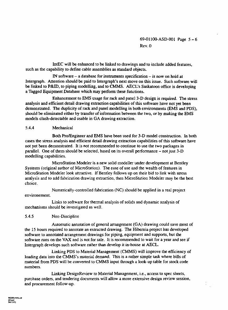
69-01100-ASD-001 Page 5 - 6
Rev. 0
IntEC will be enhanced to be linked to drawings and to include added features,such as the capability to define cable assemblies as standard objects.
IN software - a database for instruments specification - is now on hold atIntergraph. Attention should be paid to Intergraph's next move on this issue. Such software willbe linked to P&ID, to piping modelling, and to CMMS. AECL's Saskatoon office is developinga Tagged Equipment Database which may perform these functions.
Enhancement to EMS usage for rack and panel 3-D design is required. The stressanalysis and efficient detail drawing extraction capabilities of this software have not yet beendemonstrated. The duplicity of rack and panel modelling in both environments (EMS and PDS),should be eliminated either by transfer of information between the two, or by making the EMSmodels clash-detectable and usable in GA drawing extraction.
5.4.4 Mechanical
Both Pro/Engineer and EMS have been used for 3-D model construction. In bothcases the stress analysis and efficient detail drawing extraction capabilities of this software havenot yet been demonstrated. It is not recommended to continue to use the two packages inparallel. One of them should be selected, based on its overall performance - not just 3-Dmodelling capabilities.
MicroStation Modeler is a new solid modeller under development at BentleySystems (original author of MicroStation). The ease of use and the wealth of features inMicroStation Modeler look attractive. If Bentley follows up on their bid to link with stressanalysis and to add fabrication drawing extraction, then MicroStation Modeler may be the bestchoice.
Numerically-controlled fabrication (NC) should be applied in a real projectenvironement.
Links to software for thermal analysis of solids and dynamic analysis ofmechanisms should be investigated as well.
5.4.5 Non-Discipline
Automatic annotation of general arrangement (GA) drawing could save most ofthe 15 hours required to annotate an extracted drawing. The Hiberaia project has developedsoftware to annotated arrangement drawings for piping, equipment and supports, but thesoftware runs on the VAX and is not for sale. It is recommended to wait for a year and see ifIntergraph develops such software rather than develop it in-house at AECL.
Linking PDS to Material Management (CMMS) will improve the efficiency ofloading data into the CMMS's material demand. This is a rather simple task where bills ofmaterial from PDS will be converted to CMMS input through a look-up table for stock codenumbers.
Linking DesignReview to Material Management, i.e., access to spec sheets,purchase orders, and tendering documents will allow a more extensive design review session,and procurement follow-up.
942091/970*969-asd94/11/02

69-01 lOO-ASD-OOl Page 5 - 7
Rev. 0
Linking of PDS, IntEC and CMMS to Planning and Scheduling will yield betterprogress reporting.
942091/970-tf69«sd94/11/U2

69-01100-ASD-001 Page A - l
Rev. 0
APPENDIX AKOREAN REQUIREMENTS
The main contents of this section were extracted from the paper of 'The CurrentStatus and Development Plan of KEPCO Information Management System for Nuclear PowerPlants (KIMS/N)" which was issued in November 1993 in Korea. This paper stated that KEPCOneeds to fully utilize the accumulated experience of nuclear power plants operation and todevelop an information management system for nuclear power plant. The scope of KIMS/Nneeds to be determined for data integration and transparency. The plan is to cover broad range ofinformation and tasks throughout plant lifecycle from site selection to decommissioning. Thepaper describes how KIMS/N will be a large enterprise-wide system available to various users inKEPCO and other organizations such as regulatory and public bodies, research institutes, andengineering, manufacturing and construction companies. It also describes how suchsophisticated nuclear plant information system becomes possible by the fast development incomputer technology including software, hardware and network capability.
A. 1 SCOPE OF NUCLEAR PLANT DOMAIN TASKS
- Site Selection, Design and Construction
A database for site selection would consist of seismic, flood and typhoon information,geological data, etc. Design task of a nuclear power plant will require 2-D drawing images,3-D CAD/CAE data, engineering data, and so on. Construction task requires materialcontrol, construction schedule, engineering data, etc. A part of this information is sharedamong many other tasks such as operation, maintenance, PSA (Probabilistic SafetyAssessment) and plant life extension.
- Operation and Maintenance
Operation and maintenance is the area of utility's special interest. Software and databasesshall cover the following items:
1. The rapid increase of the amount of information as plant operation years increase.
2. New information need as new tasks are created.
3. New user requirements which have not been expected at the time of their developments.
- PSA
Increasing interest in operation and licensing requirement of PSA is also an importantconsideration in building KIMS/N. A database for PSA consists of mainly componentreliability information. To construct the database, it is required to establish systematic datacollection and analysis methods and organization. The database will be used in manyPSA-based applications including RCM (Reliability Centred Maintenance), living PSA,performance indicator and operator support systems.
- Radiation and Waste Management
Considering the ever growing environment concern, an efficient information management ofradiation will also be a potential area.
»«209l/970-ri>69-asd94/11/02
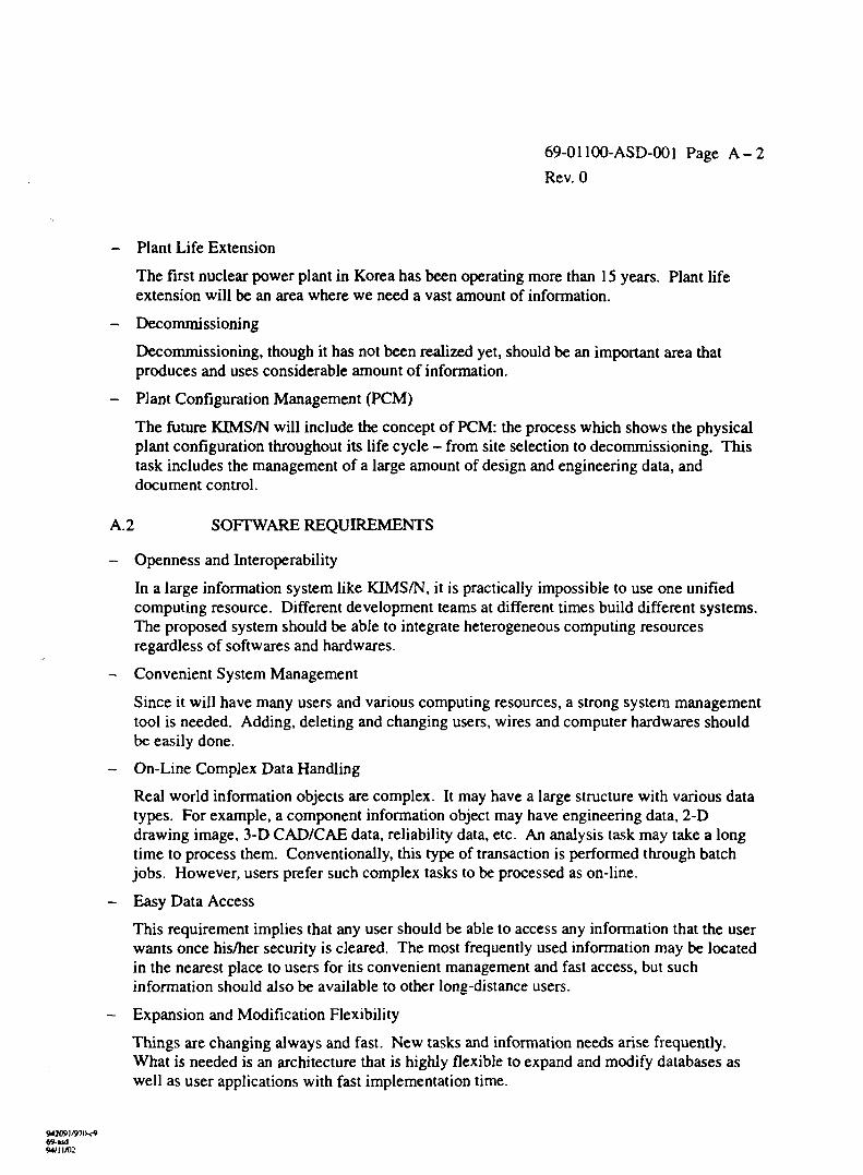
69-01100-ASD-001 Page A - 2
Rev. 0
- Plant Life Extension
The first nuclear power plant in Korea has been operating more than 15 years. Plant lifeextension will be an area where we need a vast amount of information.
- Decommissioning
Decommissioning, though it has not been realized yet, should be an important area thatproduces and uses considerable amount of information.
- Plant Configuration Management (PCM)
The future KIMS/N will include the concept of PCM: the process which shows the physicalplant configuration throughout its life cycle - from site selection to decommissioning. Thistask includes the management of a large amount of design and engineering data, anddocument control.
A.2 SOFTWARE REQUIREMENTS
- Openness and Interoperability
In a large information system like KIMS/N, it is practically impossible to use one unifiedcomputing resource. Different development teams at different times build different systems.The proposed system should be able to integrate heterogeneous computing resourcesregardless of softwares and hardwares.
- Convenient System Management
Since it will have many users and various computing resources, a strong system managementtool is needed. Adding, deleting and changing users, wires and computer hardwares shouldbe easily done.
- On-Line Complex Data Handling
Real world information objects are complex. It may have a large structure with various datatypes. For example, a component information object may have engineering data, 2-Ddrawing image, 3-D CAD/CAE data, reliability data, etc. An analysis task may take a longtime to process them. Conventionally, this type of transaction is performed through batchjobs. However, users prefer such complex tasks to be processed as on-line.
- Easy Data Access
This requirement implies that any user should be able to access any information that the userwants once his/her security is cleared. The most frequently used information may be locatedin the nearest place to users for its convenient management and fast access, but suchinformation should also be available to other long-distance users.
- Expansion and Modification Flexibility
Things are changing always and fast. New tasks and information needs arise frequently.What is needed is an architecture that is highly flexible to expand and modify databases aswell as user applications with fast implementation time.
W2091/970-C969-asd94/11AH

69-01100-ASD-001 Page A - 3
Rev. 0
- Intelligent and Well-Supporting DBMS
The vast amount of information will be located in multiple distributed databases. However,user should be able to utilize information just like using user's own database. The DBMS(not user) should be intelligent enough to provide such capability without losing significantperformance. Moreover, when information is duplicated (the same information resides inmany separate databases), the DBMS should be able to maintain consistent information.Such intelligent DBMS needs to timely support trouble-shooting of various users.
- User Friendly Interface
The system is more practical when providing friendly and highly customized end-userinterface. User program with simple manual is one of the goals of user interface. On-linehelp and common sense should be enough in using the program. Extra burden of usingcomputer can be partly resolved by friendly user interface.
- Reliability and Security
Database systems are used by many users through network. Operability of the system isemphasized by effective backup and redundancy concept. And, because the network is opento everyone, a strong security system should be maintained by hierarchical password andpermission to access.
- Strong Management and Maintenance
The system needs to be supported by strong maintenance staffs. Maintenance staffs shouldbe always readily available whenever users need help.
- Superior Performance
The above requirements can be obstacles to the performance of the system. However, byusing performance end-user client computer, the computing power can be adequatelydistributed to obtain optimal system performance.
- Data Availability
For securing data which were created on the integrated plant design and information system,it is indispensable to backup and mirror data. This should cover daily, weekly and monthlydata backup and dual concurrent data storage.
94JUIH2
69-01100-ASD-001 Page B - l
Rev. 0
APPENDIX BSTATE-OF-THE-ART COMPUTER-AIDED ENGINEERING TECHNOLOGY
As entering 1990's, there was a break-through development of computer-aidedengineering on 3-D modelling, computing speed, capacity of memory, relational databasetechnology, etc. In general, CAE software covers mechanical design toolset, analysis toolset,electronics design toolset, AEC (Architecture, Engineering and Construction) toolset,engineering-related technical toolset, etc. In this section, major functions and technologies ofthese CAE S/W capabilities are to be described.
a. Mechanical Design
• Drafting
- entities: lines, rectangles, arcs, circles, etc.
- editing functions: move, rotate, erase, trim, stretch, scale, etc.
- major functions: orthogonal, snap, grid, layer, symbol, floating-point precision,programming language (macro), automatic dimensioning, file format conversion(IGES, DXF, etc.), parametric function, etc.
• 3-D Design
- wireframe
- surface model
- solid modelling: boundary representation (B-rep), constructive solids geometry(CSG), B-splines, rational, bezier curve, parametric modelling, variational geometry,feature-based modelling.
• Rendering and Animation
- flat shading
- gourad shading
- phong shading
- photorealistic image
- ray tracing
- radiosity
- animation for analysis, visualization, presentation, illustration, and education
• Mechanical Simulation
- kinematics: analysis and synthesis of motion
- dynamics: evaluation of forces, moments, time response and natural frequencies
• Mechanical Testing
- modal analysis
- fast fourier analysis (FFS)
- soft instruments.
W2091/970-C969-ud
69-01100-ASD-001 Page B - 2
Rev. 0
b. Analysis Toolset (FEA)
• Applied Area
- structural analysis
- thermal analysis
- electromagnetic analysis
- acoustic analysis
- piezoelectric analysis
- computational fluid dynamics
- crash analysis
- simulation of plastic production processes
• Software Functionality
- pre-processing: geometry, loads, displacement constraints
- meshing: mesh density, automated meshing
- elements (3-D): tetrahedral, hexahedral, linear, quadratic, cubic, quartic,isoparametric
- solver: calculation of finite element model
- post-processing: display of the results
• Design Optimization
c. Electronics Design
• Integrated Circuits
- full-custom: the traditional IC design method
- gate array: a standard device configuration
- cell-based devices - programmable logic devices (PLDs)
• Printed-Circuit Boards (PCB)
d. AEC
• Architectural Design Area
- highway interchange
- process plant
- residential development
- shopping mall
94209l/97O-rt69«sd94/11/1)2
69-01100-ASD-001 Page B - 3
Rev. 0
• Civil Engineering Area
- digital terrain modelling
- subdivision design
- roadway design
- earthwork calculations
- mapping
- remote sensing and photography system
• Analysis - pre-processor
- solver
- post-processor
• Visualization
- rendering
- shading
- walk-through
- photorealistic images
• Facilities Management
- computer-aided facility management (CAFM): link data attributes to graphics
- graphic representation of facilities and systems (HVAC, electrical, lighting, etc.)
- textual representation of attributes, data, and specifications such as equipment modelnumber, rated electrical capacity, etc.
- data analysis including simulation and optimization models
- scheduling and tracking
- reporting features
- data exchange with other computer system
• Surveying and Mapping
- geographic information system (GIS)
e. Technical Tools
• Multimedia
- images
- animation
- full-motion video
- stereo sound
- touch-screen interaction
942091/970^969-ud94/11/02
69-01100-ASD-001 Page B - 4
Rev. 0
Technical Publishing
- text processing
- math equation editors
- mark-up languages
- desktop publishing system
- electronic technical publishing (ETP): including text processing, graphic editing,page-layout capabilities
- computer-aided logistics supports (CALS): including IGES, CGM, SGML (StandardGeneralized Markup Language), CC1T1 Group 4, AITI (Automated Interchange ofTechnical Information)
Scientific Visualization
- the process of transforming large volumes of numerical and symbolic data intopictures
Information Management
- project management: plan, organize and coordinate a design project's schedule; trackresources and costs; define workers' responsibilities
- document management: scanning, storing, retrieving and transmitting 2-Dengineering drawings; managing raster file
- vectorization or raster to vector conversion
- hybrid drawings: containing both raster and vector data
- Product Data Management (PDM): handling all of the information
- geometric and non-geometric; involving designing, analyzing and manufacturingarea; also called Engineering Data Management (EDM)
- PDM tasks of file management: accessing, transferring and archiving of engineeringdata; design review and release processes
- configuration management system: large scale project management
Communication Support
- electronic mail (E-mail)
- electronic data interchange (EDI).
942091/970*969-aid94/11/02
69-01100-ASD-001 Page C - l
Rev. 0
APPENDIX CTOOL IN USE AT MITSUBISHI AND AT EDF
Mitsubishi in Japan and Electricite de France have developed software for nuclearpower plant CAE tasks. These software packages are described below.
C.I MITSUBISHI'S NUWINGS
For improving the nuclear power plant reliability and optimization, Mitsubishideveloped nuclear plant engineering work and integrated management system, titled NUWINGS.Information on the work scope and target purpose of the NUWINGS was obtained by paper andbrochure, but detail descriptions of workflow and CAE technology which was applied toNUWINGS were not revealed. In this section, the features of NUWINGS would be described.
a. The Intent of NUWINGS
To further improve nuclear power plant reliability and how best to manage and utilize thehigh amounts of data accruing from the piping and equipment that constitute a plant becomesa vital requirement. For this purpose, it is necessary to integrate the applicable work systemsand achieve systematic data operation. "NUWINGS", developed by MHI in cooperationwith other concerned entities is a next generation engineering system which will substantiallytransform overall plant engineering through consistent information processing beginningwith design and installation, including operation and more rapid maintenance. This systemenables accurate information management and also realizes higher plant reliability by takingunrestrained advantage of the variegated, advanced functions such as verification using3-dimensional simulation.
b. New Engineering Process - From Hard Model to Soft Model
• Conventional Engineering System
In the past, for design investigation and verification, several engineering techniques havebeen adopted, that is, techniques using 2-dimensionai investigation centring on designdocumentation or 3-dimensional plastic models. However, such techniques were notalways adequate in terms of simulation function which executes both dynamically andpromptly a wide range of investigations and verifications to promote improved plantoptimization.
• New Engineering System Aiming at Plant Optimization
- Under these circumstances, MHI has developed and introduced a new design systemwhich uses computer soft modelling and takes every advantage of 3-dimensionalrepresentation using computer graphic technology to promptly and easily perform therequired investigations and verifications, aiming at plant optimization. Obviously,various qualitative effects are obtained such as the accomplishment of a wide range ofsimulation verifications including achievement of speed-up in engineering, smoothdevelopment of detail design as well as the attaining of optimum planning and plantdesign.
- NUWINGS is a system which combines a variety of design CAD and productioncontrol systems which MHI has developed and introduced for practical application
69-asd94/11/02
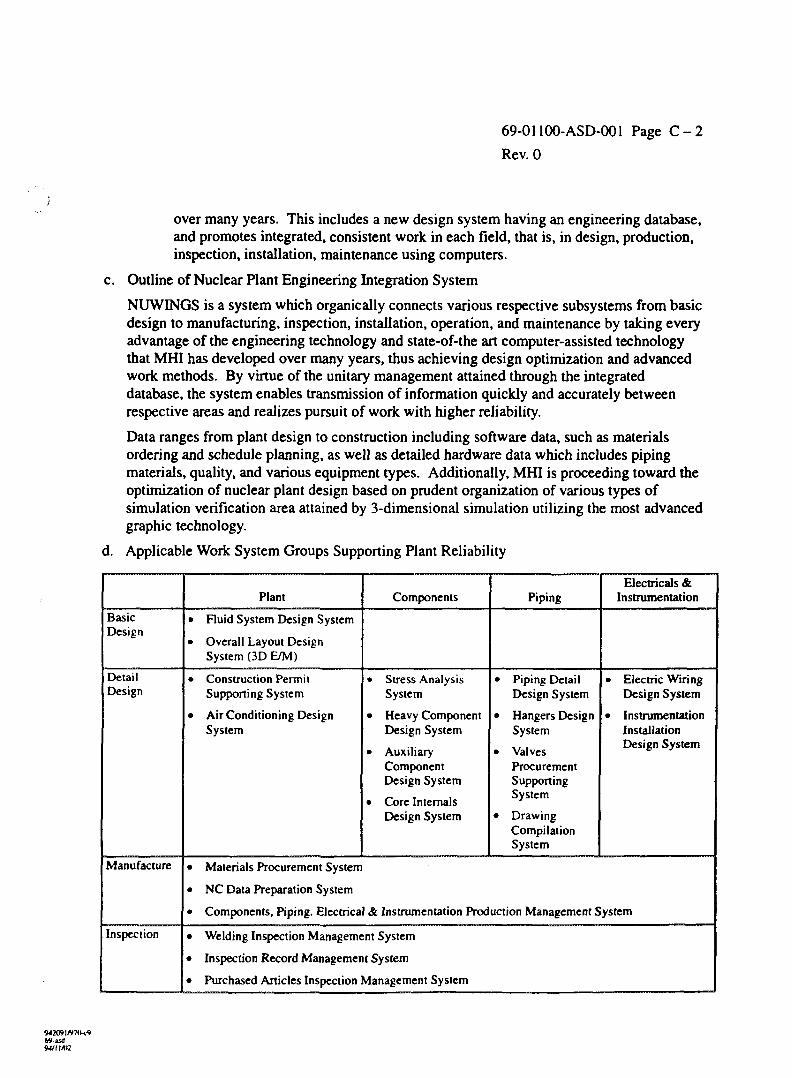
69-01100-ASD-001 Page C - 2
Rev. 0
over many years. This includes a new design system having an engineering database,and promotes integrated, consistent work in each field, that is, in design, production,inspection, installation, maintenance using computers.
c. Outline of Nuclear Plant Engineering Integration System
NUWINGS is a system which organically connects various respective subsystems from basicdesign to manufacturing, inspection, installation, operation, and maintenance by taking everyadvantage of the engineering technology and state-of-the art computer-assisted technologythat MHI has developed over many years, thus achieving design optimization and advancedwork methods. By virtue of the unitary management attained through the integrateddatabase, the system enables transmission of information quickly and accurately betweenrespective areas and realizes pursuit of work with higher reliability.
Data ranges from plant design to construction including software data, such as materialsordering and schedule planning, as well as detailed hardware data which includes pipingmaterials, quality, and various equipment types. Additionally, MHI is proceeding toward theoptimization of nuclear plant design based on prudent organization of various types ofsimulation verification area attained by 3-dimensional simulation utilizing the most advancedgraphic technology.
d. Applicable Work System Groups Supporting Plant Reliability
BasicDesign
DetailDesign
Manufacture
Inspection
Plant
• Fluid System Design System
• Overall Layout DesignSystem (3D E/M)
• Construction PermitSupporting System
• Air Conditioning DesignSystem
Components
• Stress AnalysisSystem
• Heavy ComponentDesign System
• AuxiliaryComponentDesign System
• Core InternalsDesign System
Piping
• Piping DetailDesign System
• Hangers DesignSystem
• ValvesProcurementSupportingSystem
• DrawingCompilationSystem
Electricals &Instrumentation
• Electric WiringDesign System
• InstrumentationInstallationDesign System
• Materials Procurement System
• NC Data Preparation System
• Components, Piping. Electrical & Instrumentation Production Management System
• Welding Inspection Management System
• Inspection Record Management System
• Purchased Articles Inspection Management System
94209I/V7IK9Was.)9-1/1 Mi:
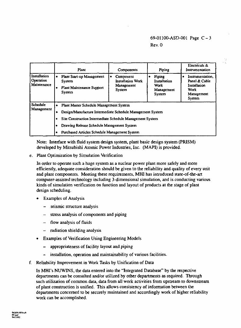
69-01100-ASD-001 Page C - 3
Rev. 0
InstallationOperationMaintenance
ScheduleManagement
Plant
• Plant Start-up ManagementSystem
• Plant Maintenance SupportSystem
Components
• ComponentInstallation WorkManagementSystem
Piping
• PipingInstallationWorkManagementSystem
Electricals &Instrumentation
• Instrumentation,Panel & CableInstallationWorkManagementSystem
• Plant Master Schedule Management System
• Design/Manufacture Intermediate Schedule Management System
• Site Construction Intermediate Schedule Management System
• Drawing Release Schedule Management System
• Purchased Articles Schedule Management System
Note: Interface with fluid system design system, plant basic design system (PRISM)developed by Mitsubishi Atomic Power Industries, Inc. (MAPI) is provided.
e. Plant Optimization by Simulation Verification
In order to operate such a huge system as a nuclear power plant more safely and moreefficiently, adequate consideration should be given to the reliability and quality of every unitand plant components. Meeting these requirements, MHI has introduced state-of-the-artcomputer-assisted technology including 3-dimensional simulation, and is conducting variouskinds of simulation verification on function and layout of products at the stage of plantdesign scheduling.
• Examples of Analysis
- seismic structure analysis
- stress analysis of components and piping
- flow analysis of fluids
- radiation shielding analysis
• Examples of Verification Using Engineering Models
- appropriateness of facility layout and piping
- installation, operation and maintainability of various facilities.
f. Reliability Improvement in Work Tasks by Unification of Data
In MHI's NUWINS, the data entered into the "Integrated Database" by the respectivedepartments can be consulted and/or utilized by other departments as required. Throughsuch utilization of common data, data from all work activities from upstream to downstreamof plant construction is unified. This allows consistency of information between thedepartments concerned to be securely maintained and accordingly work of higher reliabilitywork can be accomplished.
69-asd94/1IIU2
69-01100-ASD-001 Page C - 4
Rev. 0
g. Database Management System Assuring Data Reliability
NUWINGS assumes work promotion of higher reliability by permitting unitary managementand shared use among the departments concerned through its "Integrated Database", whichincludes all types of information and data necessary for plant construction, plus the datagenerated through work progress. Additionally, three management functions, that is, "StatusManagement", "Alteration Management" and "Access Management", are incorporated toensure the reliability of data entered into the "Integrated Database". These functions locatethe responsibility for data registration and utilization and prevent any occurrence of workconfusion caused by double registration of the same data or data access by unauthorizedparties. Restriction of data utilization is applied in accordance with the three types of statusas referred to below. Therefore, data can be utilized on the basis of data positioning (status),which prevents any possible work confusion.
h. Configuration of Integrated Database
• basic design data
• detail design data
• production design data
• material procurement data
• manufacturing data
• inspection data
• installation data
• start-up data
• schedule planning data
• progress-in-schedule data
• technology management data
• various standards data
i. From Design to Installation, Operation Variegated System Promises Plant Optimization
MHI's NUWINGS aims at optimum plant realization by taking complete advantage ofadvanced computer-assisted technology, that is, by incorporating organically variegatedsubsystem of each process from design to manufacture, inspection, installation, operation,and maintenance under unitary information management through an integrated database, andby adopting FA for manufacturing lines, introducing expert systems, as well as utilizing3-dimensional soft model engineering and FEM analysis technology. Each design scopecovers as follows.
• Conceptual Design
- plot plan
- building appearance view
- sectional view of building
94M9J/97O-C969-asd
69-01100-ASD-001 Page C - 5
Rev. 0
Basic Design
- system design system
- electrical and instrumentation design system
- air conditioning design system
- system for preparing application documents for approval of construction plan
Layout and Piping Design
- overall layout design system
- piping design system
- simulation system
- overall layout and piping drawing
Detail Design
- control rod drive mechanism analysis system
- fuel assembly stress analysis system
- steam generator design system
- steam generator internal structures design system
- fuel design system
- core component design system
- heavy component and auxiliary component design system
- robot design support system
Procurement and Manufacture
- piping manufacturing drawing system
- supports manufacturing drawing system
- electrical and wiring design drawing system
- purchased articles procurement support system
- piping manufacturing system (FA system)
- piping, component, instrumentation manufacturing management system
- production preparation system (NC tape preparation)
- CAM system
Inspection
- piping welding inspection system
- fuel rod inspection simulation system
- purchased articles inspection system
M/ll/02
69-01100-ASD-001 Page C - 6
Rev. 0
• Installation
- piping module installation planning system
- installation work management system
• Overall Schedule Management System
- plant overall schedule system
- design and manufacture medium schedule management system
- construction schedule management system
- drawing release management system
C.2 EDFS PHENIX
To reduce human errors probability in I&C and operation area, Framatome'sElectricite de France (EDF) had built three phases I&C development plan during 1981-1993. Inthis section, major tasks of each phase and EDF's CAD System (PHENIX) would be describedroughly because the information was extracted from the training handout "French N4 1450 MWeClass Plant I&C Design Presentation, November 1-6, 1990".
a. Major Tasks of Each Phase
• Phase 1: Functional and Organizational Analysis, 1981-1982
- analysis of the operators tasks
- analysis of the allocation of functions to the man and to the machine (automation)
- functional analysis of the operating procedures
- identification of the use of plant information and control
- identification of the relations between operating and maintenance teams
• Phase 2 Feasibility Study and Conceptual Design, 1982-1984
- design of the new control room: specifications of data processing, alarm processing,and dialogues and images features
- design of the operator's desks: number of CRT needed, choice of means of dialogue,rules for dialogues and information access
- specifications fo the full scope simulator
- feasibility studies of a distributed computerized system of I&C
- studies of a technological evolution of the system of I&C in the 1300 MW PWR units
- development of CAD tools
• Phase 3: Detail Design and Implementation, 1984-1992
- detailed functional specifications of I&C system
- general architecture of I&C system
69-01100-ASD-001 Page C - 7
Rev. 0
- specifications of controllers, reactor protection system and reactor rod regulation
- evaluation and validation of the control room on the full scope simulator
- realization studies of the unit 1 and 2 of CHOOZ B
b. EDF's CAD System
• CAD History (1984)
- pipework: PDMS
- isometrics: COMPAID
- stress analysis: POUX
- bill of material: PHOENIX
- P&ID: PHOENIX
- electrical diagrams: PHOENIX
- cables: PDMS, PHOENIX, PERICLES
• EDF's CAD Environment (1989)
- over 300 people formed
- about 200 graphic terminals
- about 150 simultaneous users
- all N4 studies on a mainframe
• PHOENIX's descriptions
- 2-D graphical software created by ASC (Advanced Systems Calculations,Cambridge, U.K.)
- programming language: FORTRAN
- portable hardware: VAX, PRIME, IBM, UNIX-W/S
- database management system: DB2
- document control system
- data sharing: P&ID, F/S, PLC (Boolean logic description), cabling diagrams (reactorwall penetrations), single line diagrams, material management
• Design Software Chart
• I&C CAD Data Flow
W2WI/970-C9
9*11/02
69-01100-ASD-001 Page D - l
Rev. 0
APPENDIX DRACK AND PANEL DESIGN WITH EMS AND PDM/PDU
This description of rack and panel design is based on AECL 74-60000-DG-003Rev. 0. Rack and panel design uses Intergraph's mechanical modelling software, EngineeringModel System (EMS) to create graphics model files. The graphics are linked via intelligentlinks to an Informix relational database. Linking and managing of graphic and non-graphicinformation in the database is through Intergraph's.
The Informix database contains panel catalogues which define parts attributes.
A number of AECL-developed panel utilities allow panel design usingalphanumeric terminals. These utilities include a Create/Copy, Update/Copy, Purge and Post.
Rack and Panel design is integrated with overall plant design through "soft" links.The soft information links allow data to flow across the database to other application products,for example Plant Design (PDS), Electrical Engineering and Panel Wiring environments.Information is the single point entry which reduces the risk of error. Error risk is further reducedby data validation schemes. Rack and Panel design uses two applications linked to an Informixdatabase. These products are (See also Section 3.3.7 in this document):
- Engineering Modeling System (EMS)
- Product Data Manager/User (PDM/PDU).
Records in the database are grouped into catalogues. The following standardcatalogues are provided:
- Sheetmetal
- Hardware
- Label
- Devices
- Loops
- Mechanical Subassembly
- Mechanical Assembly
- Wire Subassembly
- Wire Assembly
- Panels
Informix Utilities
Rack and panel design, in addition to the graphics (EMS) and parts manager(PDM/PDU), rack and panel design uses some AECL developed programs which are based onInformix utilities. These utilities are Informix SQL and Informix 4GL. Informix SQL providesinteractive access to the PDM database to query and manipulate the data. Informix 4GL is usedto produce the source code for the rack and panel design utilities described earlier. 4GL is alsoused to customize form presentation, that is what data is presented and how the information ispresented.
942091/97Oc969-asd
o69-01100-ASD-001 Page D - 2
Rev. 0
Rack and Panel Drawing Extraction
Drawing extraction can be described as a three state process. A 3-D model isplaced on a drawing sheet which is set up to ISO standards and meets AECL drawing formatstandards. Once a model is traced along its edges, thus transforming the 3-D model into 2-Dplanar graphics, the 2-D graphics resulting from that process are stored in a separate file.Drawing references and annotations per AECL's Drawing Office Manual are added to the 2-Dfile. The 2-D file can then be plotted if necessary to create hardcopy for issue purposes.
Integration with Other Design Applications
A number of interface requirements occur in rack and panel design. These can becategorized as import or export requirements. Import requirements are:
- Device attributes defined in the PDS IN database.
- Loop configuration, device assignment and panel allocation defined in the PDS P&IDapplication.
- Field instrument tubing configuration defined in the PDS Piping application.
- Export requirements are:
- Panel terminal configuration to panel wiring software.
- Envelope panel outlines to the PDS environment for PDS EQP space allocation.
- Panel number assignments to PDS for P&ID application.
- Relay and I/O cage assignment to EE applications.
- Device part numbers to PDS for the PDS IN application.
Transfer of data will generally be through direct connections between thedifferent design databases. With the transfer of all design packages to a common operatingsystem and relational database system, this will be easier than the process adopted by CANDU3which had to cater to disparate operating and database systems.
Panel graphics (EMS files) must be converted to Microstation format for viewingin the PDS environment. EMS provides this functionality. PDS Piping allows verification offiled tube run connections with rack loop arrangements. PDS EQP permits space allocationwithin the overall plant context. EQP files are further transferred to Design Review orModelview to evaluate interferences and to review layout.
For most cases, device data is defined in PDS IN which is soft linked to the paneldesign environment. Non PDS IN devices will be defined in the appropriate device or loopcatalogues in the rack and panel design environment.
942f)9H97C>-c969-isdM/11A0
69-01100-ASD-001 Page D - 3
Rev. 0
Export
Panel terminal configuration and tagging is defined in the panel designenvironment. The panel wiring software looks at each panel to determine the terminal allotment.The panel design further targets allotment and tagging of relay and I/O modules used in the EEenvironment. Wire and device relationships are defined in the electrical diagrams, thereforesufficient terminals/modules should be provided by the user to accommodate all devices. Adiscrepancy report can be provided on demand to identify deficiencies in terminal/moduleallocations.
Device part numbers are required to be exported to PDS IN where devices aredefined in full detail for design and procurement purposes. On CANDU3 data was transferredmanually since the PDM catalogues and the IN database reside on different operating systemsand used different database systems. With the release of the UNDC/Informix based PDS IN, thistransfer will be done electronically. The device part number is registered in the 'eee' database tobe utilized by other software, such as panel wiring. It is also available in the PDS environmentvia the PDS IN task.
For each panel placed in the plant, volume requirements need to be defined in theplant model via the equipment modeling software (PDS EQP). A Microstation file, generatedfrom the EMS graphics, is transferred to PDS EQP.
Conversion of a complete EMS graphics file will almost certainly result in a verylarge Microstation file. To reduce storage requirements and to improve system response, anenvelope profile only is created for each panel. This is sufficient to reserve space in the plantmodel for a panel, though a fully detailed panel model is only viewable via EMS.
Import
A number of attributes defined in PDS IN are duplicated in the panel designdevice catalogue. With the UNDC/Informix version of IN, these attributes will be availableelectronically rather than manually as was the case with CANDU3. The attributes are certainphysical device parameters such as wetted process connections and conduit connection details.
0 9 1«9-asd94/11/02
69-01100-ASD-001 Page E - l
Rev. 0
APPENDIX ECMMS SOFTWARE
Material and equipment supply for a CANDU reactor is worth about a quarter to athird of the project cost. The main function of the supply organization at AECL is to manage thedelivery of the material required to construct and commission the station. In addition, AECLdesires to hand over the station to the Owner in good order and with an accurate inventory ofspares and other material. The principal software used at AECL CANDU to accomplish thisfunction is the CANDU Material Management System (CMMS). CMMS is intended to providean integrated, comprehensive information base to support AECL's material and equipmentcataloguing and acquisition. CMMS covers all aspects of a design/build project as detailedbelow. CMMS also provides "monitors" which compare and report on discrepancies betweendifferent phases of the project. For example, material demand identified by the design iscompared with material ordered to minimize cost overruns due to either material shortages orunjustified material overages. CMMS also provides a material catalogue of material used onprevious CANDU projects to aid in standardizing material from project to project. To ensurethat CMMS would operate on a wide variety of computer platforms, it was developed on anOracle database engine. Its' development was dictated by the fact that AECL was unable to findany comparable commercial offering.
Material Lifecycle
In CMMS terms, the following events comprise material lifecycle:
- Contract, a definition of contractual obligations for component design and materialprocurement.
- Design, a definition of specifications for materials.
- Engineering Requisition, a definition of material purchase requirements.
- Purchase, procurement of material from suppliers.
- Inventory, temporary storage or staging of materials in preparation for utilization of thematerial in the project.
- Construction, installation or consumption of material into the plant.
CMMS Functionality
CMMS is intended to cover all aspects of material lifecycle as defined inSection 3.5.4 fo this report. This section outlines the main functions of CMMS.
The Baseline represents a preliminary estimate of the probable project materialrequirements based on previous experience with similar projects. Its function is to allow thepreparation of preliminary EQR's and to allow setting up schedules before the true station designhas been firmed up.
M209l/97O<969-isdM/ll/02

69-01100-ASD-001 Page E - 2
Rev. 0
Design Demand is defined in CMMS by the bills of material for the project. Eachbill of material is related to a project design document and identifies each of the items requiredto build the assembly shown on the drawing. Each item on the bill of material bears an AECLmaterial catalogue number, the quantity of the item required to construct the assembly, and thenature of the related supply activity for the item (i.e., which organization is responsible for itssupply and whether it is to be supplied by itself or as part of a larger assembly). These electronicbills contain the data normally printed out as configured documents and in addition, detailedcross-links to sub-bills, to instrument lists, and to procurement-related documents such as EQRSand purchase orders.
An Engineering Quotation Request (EQR) initiates procurement activity,exclusively. An EQR is compiled by Design Engineering and is grouped in a manner which canbe conveniently purchased, for example by material type.
A Request for Tender (RFT) is a document which assembles EQR based demandwith commercial and technical terms and conditions for the purpose of being issued to qualifiedbidders and soliciting price and material availability. A successful bidder will be awarded acontract to supply the material in the RFT under the terms and conditions stated in the RFT, asmodified by normal tendering process practices. CMMS only maintains data necessary togenerate the price schedule of an RFT.
A Purchase Order (PO) is used to define the Supply side of the Demand/Supplyequation. The purpose of the supply process is to have Supply equal Demand. A PO is trackedin CMMS to monitor the actual state of material ordered on each PO.
CMMS provides a facility to measure inventoried material at a construction site.Material enters inventory as a result of successful delivery of a PO line item. Material leavesinventory in response to a Construction Work Package (CWP). CMMS contains an inventoryadjustment to allow inventory updating due to damaged material etc.
CMMS Features
CMMS has a number of features which are described in this section. They are:
- Material Catalogue
- External Organization (Supplier File)
- Procurement Monitors
- Document Generation
- Document Approval and Status
- Record Timestamping
- Security
- Design
- Instrument Lists
- Site Inventory
- Construction Work Package
W2O91/97O-C969-jsd
69-01100-ASD-001 Page E - 3
Rev. 0
Material Catalogue
Perhaps central to all CMMS functions is the Material Catalogue. The MaterialCatalogue is a compilation of all materials and services required to be contracted for to completea nuclear power plant. The Material Catalogue is common to all CMMS functions. If the clientrequests, a common catalogue may be shared by several projects.
The Material Catalogue contains attributes describing of all materials and servicesrequired by projects including four description fields and a list of fields covering Jurisdictionaland ASME Code requirements. Material codes are unique within CMMS.
Procurement Monitors
Procurement monitors are provided to ensure that all items shown on a Bill ofMaterial are requisitioned on an EQR, all items requisitioned on an EQR are ordered on a POand that all items ordered on a PO are delivered to the site warehouse. It is important to note thatalthough material supply should exactly equal material demand, there will be cases where thesupply can exceed the demand without breaking prudent business principles. User judgement isapplied to decide whether an apparent excess supply condition will be consumed by constructionor commissioning processes.
Document Generation
CMMS is the source of many documents used within the project. The major onesare:
- Bills of Material (BM)
- Instrument Lists
- Equipment Lists
- Engineering Quotation Request Item Lists (EQR)
- Request for Tender Item Lists (RFT)
- Purchase Order Item Lists (PO).
- Receiving Reports
- Construction Work Package Item List
- Material Issue Reports.
The usefulness of CMMS lies in the fact that all of the information on thedifferent lists is interrelated and the CMMS system manages the details of these relationships.For example, a bill of material identifies all of the items required to build an assembly. Thedetails of the item descriptions are maintained in the material catalogue. Each of the items onthe bill is flagged to indicate who is responsible for purchasing the item - AECL, AECL's client,or a supplier.
«9-asd94/11/02

69-01100-ASD-001 Page E - 4
Rev. 0
When an engineer wishes to prepare an EQR a set of criteria are supplied toCMMS and CMMS examines all of the bills of material in the system to locate items which:
- meet the listed criteria
- have not been designated for purchase on another EQR
- are the responsibility of AECL to supply.
The engineer will then edit this list to do such things as add spare parts forassemblies, add documentation requirements, or fine-tune the listing.
At all times the one-to-one relationship between the items on the bills of materialand the items in the EQR is maintained by CMMS. This relationship is carried through thesubsequent stages of RFT, PO, site receival, and site issuing of material
Document Status
Key documents in CMMS can have one of the following states:
- Non-Approved (Pending)
- Approved
- Interim Approved
In a Non-Approved state, any data in a document may be changed as allowed bybusiness rules.
In an Approved state, selected attributes and entities for BoMs, EQR's and PO'sare locked, prohibiting changes. All attributes appearing on an Item List are considered locked.The Baseline screen locks all entities and attributes in an approved state. Locking means that therevision level of the document must be raised before changes to the controlled information in thedocument may be made.
An Interim Approved document behaves like an Approved document, with theexception that the revision of an Interim Approved document does not have to be increased if thedocument status changes. Interim Approval allows a "draft" of a document to be locked until itscontents are verified as correct, or alternatively changed to be correct.
Record Time-stamping
Time stamps are used to log the last update made to records within the CMMSdatabase. Documents have a Master/Detail relationship between a document and line items thatit may contain. A document is always the master. A line item is the master for a topic (ieremarks). Changes to a detail item's time stamp have an upward cascading effect on the masteritem or items.
69-asd94/11/02
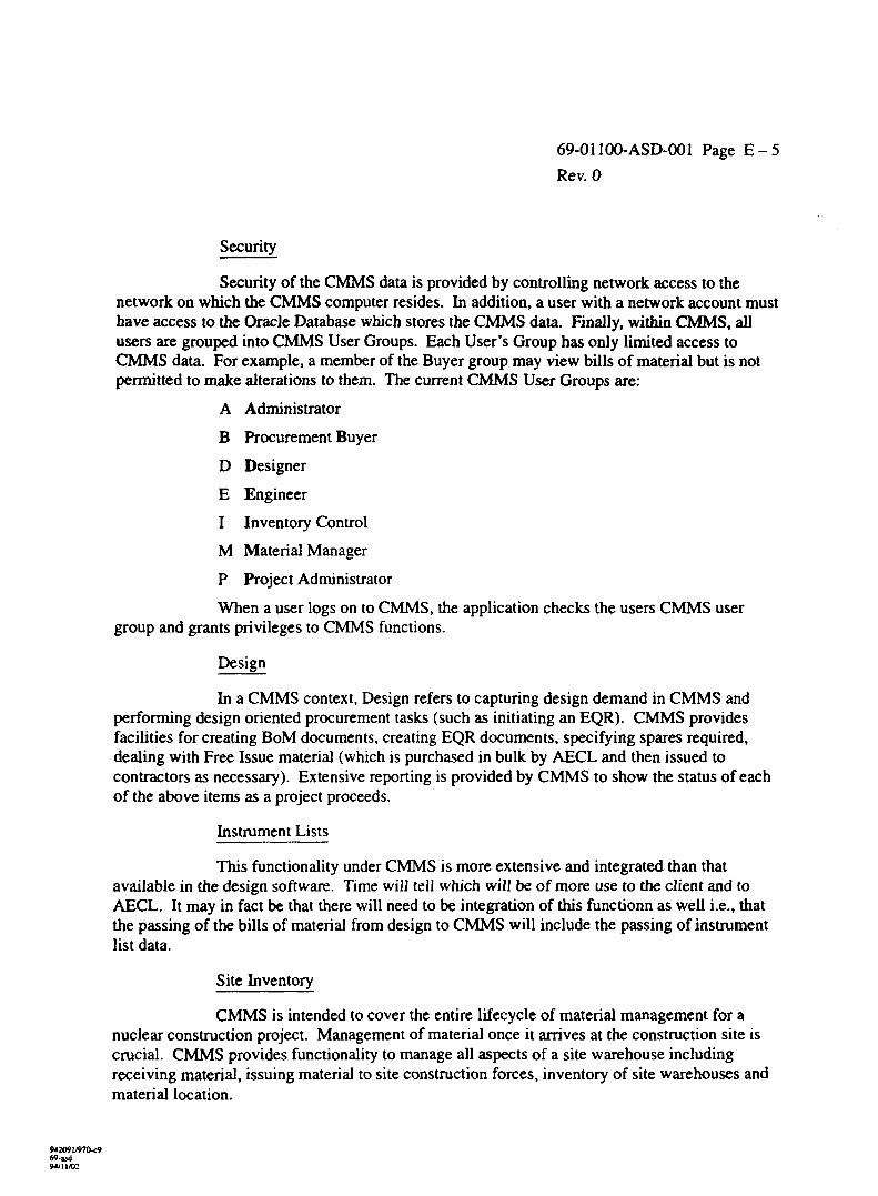
69-01100-ASD-001 Page E - 5
Rev. 0
Security
Security of the CMMS data is provided by controlling network access to thenetwork on which the CMMS computer resides. In addition, a user with a network account musthave access to the Oracle Database which stores the CMMS data. Finally, within CMMS, allusers are grouped into CMMS User Groups. Each User's Group has only limited access toCMMS data. For example, a member of the Buyer group may view bills of material but is notpermitted to make alterations to them. The current CMMS User Groups are:
A Administrator
B Procurement Buyer
D Designer
E Engineer
I Inventory Control
M Material Manager
P Project Administrator
When a user logs on to CMMS, the application checks the users CMMS usergroup and grants privileges to CMMS functions.
Design
In a CMMS context, Design refers to capturing design demand in CMMS andperforming design oriented procurement tasks (such as initiating an EQR). CMMS providesfacilities for creating BoM documents, creating EQR documents, specifying spares required,dealing with Free Issue material (which is purchased in bulk by AECL and then issued tocontractors as necessary). Extensive reporting is provided by CMMS to show the status of eachof the above items as a project proceeds.
Instrument Lists
This functionality under CMMS is more extensive and integrated than thatavailable in the design software. Time will tell which will be of more use to the client and toAECL. It may in fact be that there will need to be integration of this functionn as well i.e., thatthe passing of the bills of material from design to CMMS will include the passing of instrumentlist data.
Site Inventory
CMMS is intended to cover the entire lifecycle of material management for anuclear construction project. Management of material once it arrives at the construction site iscrucial. CMMS provides functionality to manage all aspects of a site warehouse includingreceiving material, issuing material to site construction forces, inventory of site warehouses andmaterial location.
94309I/97O-C969-asd9*>11A)2

69-01100-ASD-001 Page E - 6
Rev. 0
Construction Work Package
Construction Work Packages (CWP) represent the final demand against materialsupply. CMMS is able through its site inventory to track issuing material to site constructionforces via approved Construction Work Packages. CMMS also provides a "roll up" ofconstruction demand in the CWP screens using a Document Monitor screen. CMMS canproduce CWP item lists. One of the near-term improvements will be the use of bills of materialsas a semi-automatic resource for the generation of CWP's.
69-asdMM 1/02
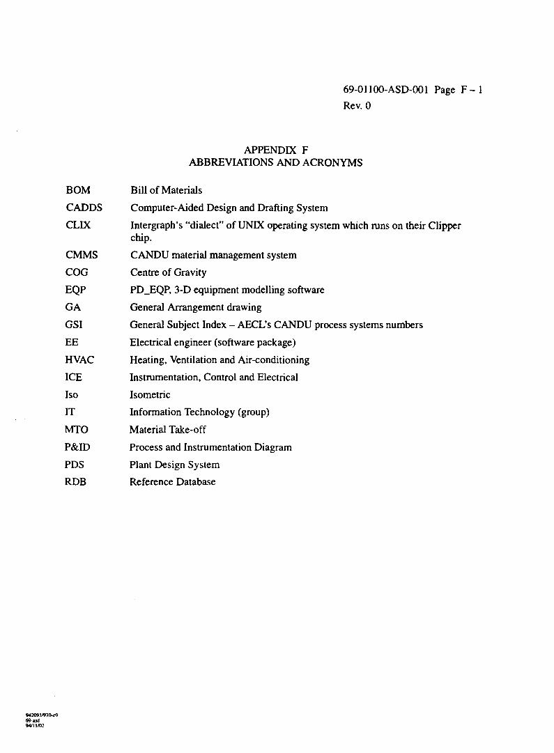
69-01100-ASD-001 Page F - l
Rev. 0
APPENDIX FABBREVIATIONS AND ACRONYMS
BOM Bill of Materials
CADDS Computer-Aided Design and Drafting System
CLIX Intergraph's "dialect" of UNIX operating system which runs on their Clipperchip.
CMMS CANDU material management system
COG Centre of Gravity
EQP PD_EQP, 3-D equipment modelling software
GA General Arrangement drawing
GSI General Subject Index - AECL's CANDU process systems numbers
EE Electrical engineer (software package)
HVAC Heating, Ventilation and Air-conditioning
ICE Instrumentation, Control and Electrical
Iso Isometric
IT Information Technology (group)
MTO Material Take-off
P&ID Process and Instrumentation Diagram
PDS Plant Design System
RDB Reference Database
942091/970*969-ud9*11/02
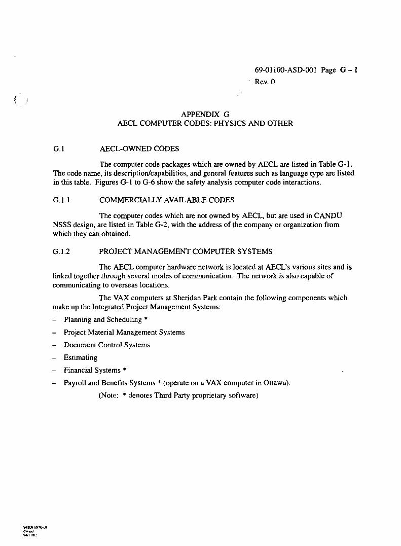
69-01100-ASD-001 Page G-l
Rev. 0
APPENDIX GAECL COMPUTER CODES: PHYSICS AND OTHER
G.I AECL-OWNED CODES
The computer code packages which are owned by AECL are listed in Table G-l.The code name, its description/capabilities, and general features such as language type are listedin this table. Figures G-l to G-6 show the safety analysis computer code interactions.
G. 1.1 COMMERCIALLY AVAILABLE CODES
The computer codes which are not owned by AECL, but are used in CANDUNSSS design, are listed in Table G-2, with the address of the company or organization fromwhich they can obtained.
G. 1.2 PROJECT MANAGEMENT COMPUTER SYSTEMS
The AECL computer hardware network is located at AECL's various sites and islinked together through several modes of communication. The network is also capable ofcommunicating to overseas locations.
The VAX computers at Sheridan Park contain the following components whichmake up the Integrated Project Management Systems:
- Planning and Scheduling *
- Project Material Management Systems
- Document Control Systems
- Estimating
- Financial Systems *
- Payroll and Benefits Systems * (operate on a VAX computer in Ottawa).
(Note: * denotes Third Party proprietary software)
942091/97O<9
94/11/02
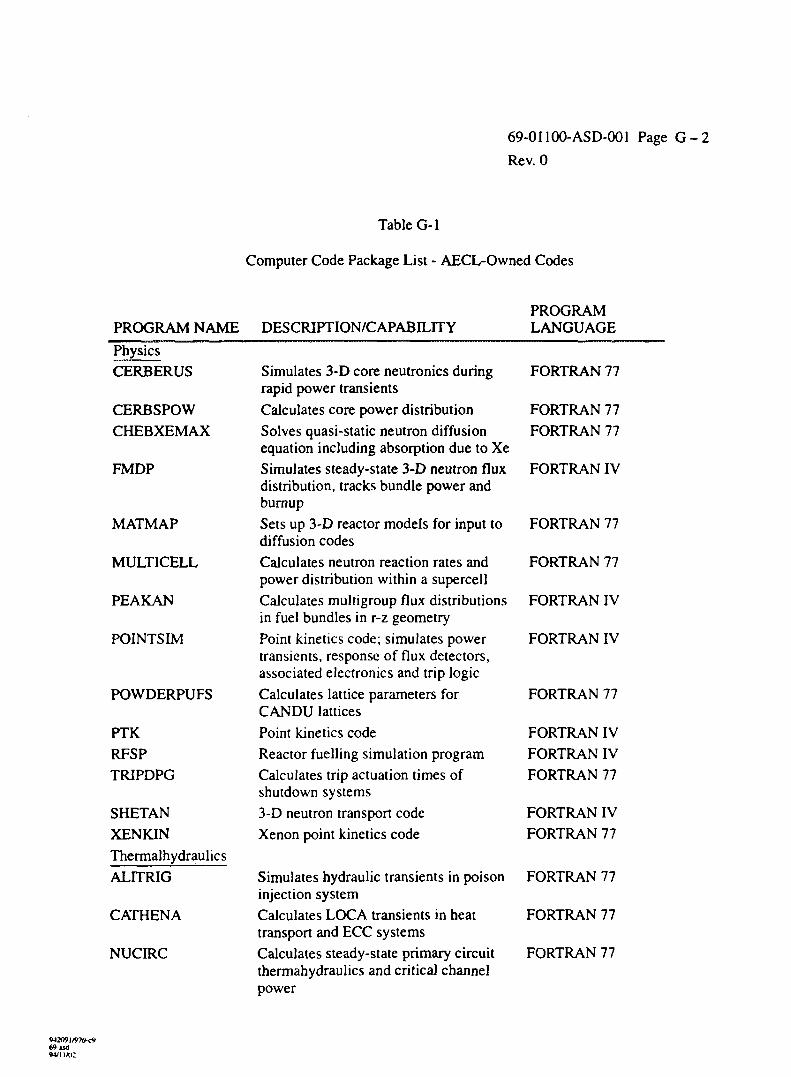
69-01100-ASD-001 Page G - 2
Rev. 0
Table G-l
Computer Code Package List - AECL-Owned Codes
PROGRAM NAME DESCRIPTION/CAPABILITYPROGRAMLANGUAGE
Physics
CERBERUS
CERBSPOW
CHEBXEMAX
FMDP
MATMAP
MULTICELL
PEAKAN
POINTSIM
POWDERPUFS
PTK
RFSP
TRIPDPG
SHETAN
XENKIN
Thermalhydraulics
ALITRIG
CATHENA
NUCIRC
Simulates 3-D core neutronics duringrapid power transients
Calculates core power distribution
Solves quasi-static neutron diffusionequation including absorption due to Xe
Simulates steady-state 3-D neutron fluxdistribution, tracks bundle power andburnup
Sets up 3-D reactor models for input todiffusion codes
Calculates neutron reaction rates andpower distribution within a supercell
Calculates multigroup flux distributionsin fuel bundles in r-z geometry
Point kinetics code; simulates powertransients, response of flux detectors,associated electronics and trip logic
Calculates lattice parameters forCANDU lattices
Point kinetics code
Reactor fuelling simulation program
Calculates trip actuation times ofshutdown systems
3-D neutron transport code
Xenon point kinetics code
Simulates hydraulic transients in poisoninjection system
Calculates LOCA transients in heattransport and ECC systems
Calculates steady-state primary circuitthermahydraulics and critical channelpower
FORTRAN 77
FORTRAN 77
FORTRAN 77
FORTRAN IV
FORTRAN 77
FORTRAN 77
FORTRAN IV
FORTRAN IV
FORTRAN 77
FORTRAN IV
FORTRAN IV
FORTRAN 77
FORTRAN IV
FORTRAN 77
FORTRAN 77
FORTRAN 77
FORTRAN 77
69-ud94/IIAI2
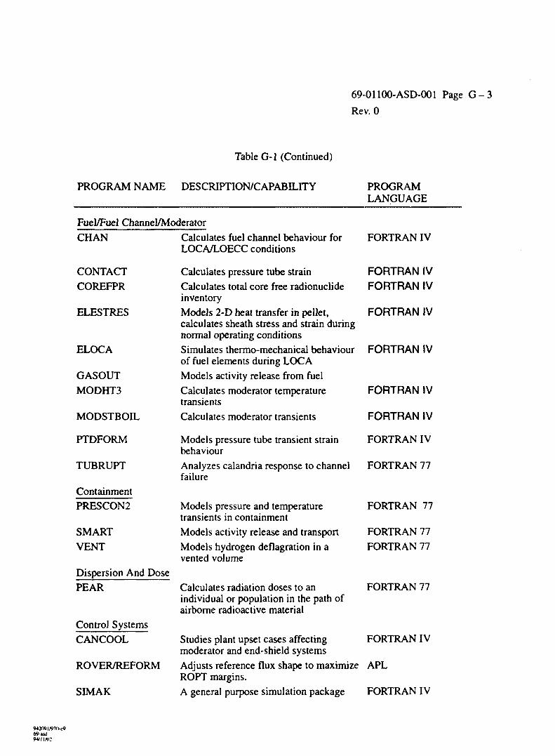
Table G-l (Continued)
69-01100-ASD-001 Page G - 3
Rev. 0
PROGRAM NAME DESCRIPTION/CAPABILITY PROGRAMLANGUAGE
Fuel/Fuel Channel/ModeratorCHAN
CONTACTCOREFPR
ELESTRES
ELOCA
GASOUTMODHT3
MODSTBOIL
PTDFORM
TUBRUPT
ContainmentPRESCON2
SMARTVENT
Dispersion And DosePEAR
Control SystemsCANCOOL
ROVER/REFORM
SIMAK
Calculates fuel channel behaviour forLOCA/LOECC conditions
Calculates pressure tube strainCalculates total core free radionuclideinventoryModels 2-D heat transfer in pellet,calculates sheath stress and strain duringnormal operating conditionsSimulates thermo-mechanical behaviourof fuel elements during LOCAModels activity release from fuelCalculates moderator temperaturetransientsCalculates moderator transients
FORTRAN IV
FORTRAN IVFORTRAN IV
FORTRAN IV
FORTRAN IV
FORTRAN IV
FORTRAN IV
Models pressure tube transient strain FORTRAN IVbehaviourAnalyzes calandria response to channel FORTRAN 77failure
Models pressure and temperaturetransients in containmentModels activity release and transportModels hydrogen deflagration in avented volume
Calculates radiation doses to anindividual or population in the path ofairborne radioactive material
FORTRAN 77
FORTRAN 77FORTRAN 77
FORTRAN 77
FORTRAN IVStudies plant upset cases affectingmoderator and end-shield systemsAdjusts reference flux shape to maximize APLROPT margins.A general purpose simulation package FORTRAN IV
W2O9I/97O-C969-iul
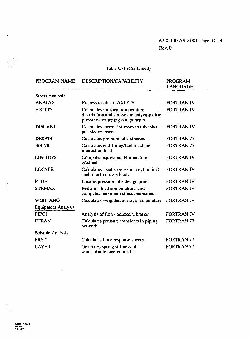
69-01100-ASD-001 Page G - 4
Rev. 0
Table G-l (Continued)
PROGRAM NAME
Stress AnalysisANALYS
AXITTS
DISCANT
DESPT4
EFFMI
LIN-TDPS
LOCSTR
PTDESTRMAX
WGHTANGEquipment AnalysisPIPO1PTRAN
Seismic AnalysisFRS-2LAYER
DESCRIPTION/CAPABILITY
Process results of AXITTS
Calculates transient temperaturedistribution and stresses in axisymmetricpressure-containing componentsCalculates thermal stresses in tube sheetand sleeve insertCalculates pressure tube stressesCalculates end-fitting/fuel machineinteraction loadComputes equivalent temperaturegradientCalculates local stresses in a cylindricalshell due to nozzle loadsLocates pressure tube design point
Performs load combinations andcomputes maximum stress intensitiesCalculates weighted average temperature
Analysis of flow-induced vibrationCalculates pressure transients in pipingnetwork
Calculates floor response spectraGenerates SDrine stiffness of
PROGRAMLANGUAGE
FORTRAN IV
FORTRAN IV
FORTRAN IV
FORTRAN 77
FORTRAN 77
FORTRAN IV
FORTRAN IV
FORTRAN IVFORTRAN IV
FORTRAN IV
FORTRAN IVFORTRAN 77
FORTRAN 77FORTRAN 77
semi-infinite layered media
SW 2091/970-c969-asd
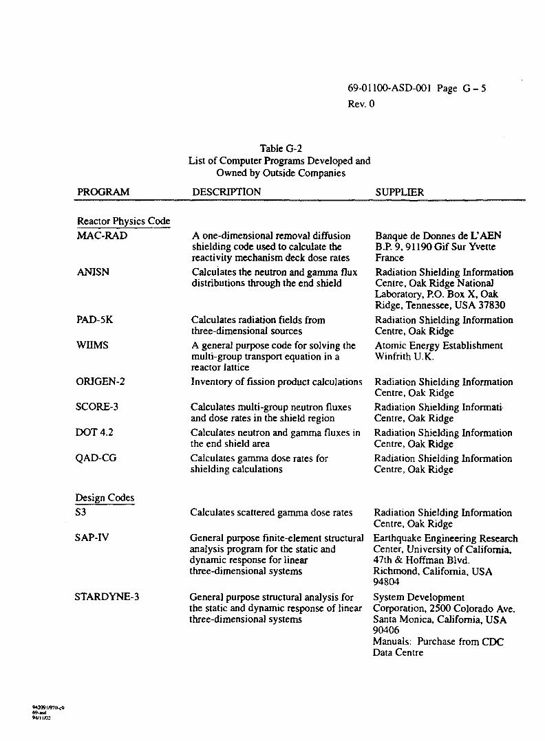
69-01100-ASD-001 Page G - 5
Rev. 0
PROGRAM
Table G-2List of Computer Programs Developed and
Owned by Outside Companies
DESCRIPTION SUPPLIER
Reactor Physics CodeMAC-RAD
ANISN
PAD-5K
WHMS
ORIGEN-2
SCORE-3
DOT 4.2
QAD-CG
A one-dimensional removal diffusionshielding code used to calculate thereactivity mechanism deck dose ratesCalculates the neutron and gamma fluxdistributions through the end shield
Calculates radiation fields fromthree-dimensional sourcesA general purpose code for solving themulti-group transport equation in areactor latticeInventory of fission product calculations
Calculates multi-group neutron fluxesand dose rates in the shield regionCalculates neutron and gamma fluxes inthe end shield areaCalculates gamma dose rates forshielding calculations
Banque de Donnes de L'AENB.P. 9,91190 Gif Sur YvetteFranceRadiation Shielding InformationCentre, Oak Ridge NationalLaboratory, P.O. Box X, OakRidge, Tennessee, USA 37830Radiation Shielding InformationCentre, Oak RidgeAtomic Energy EstablishmentWinfrith U.K.
Radiation Shielding InformationCentre, Oak RidgeRadiation Shielding InformatiCentre, Oak RidgeRadiation Shielding InformationCentre, Oak RidgeRadiation Shielding InformationCentre, Oak Ridge
Design Codes_
SAP-IV
STARDYNE-3
Calculates scattered gamma dose rates
General purpose finite-element structuralanalysis program for the static anddynamic response for linearthree-dimensional systems
General purpose structural analysis forthe static and dynamic response of linearthree-dimensional systems
Radiation Shielding InformationCentre, Oak RidgeEarthquake Engineering ResearchCenter, University of California,47th & Hoffman Blvd.Richmond, California, USA94804System DevelopmentCorporation, 2500 Colorado Ave.Santa Monica, California, USA90406Manuals: Purchase from CDCData Centre
W 2091/970. c9W-udwm/o:
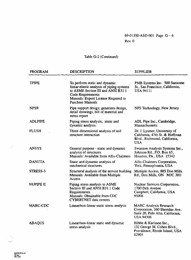
69-01100-ASD-001 Page G - 6
Rev. 0
Table G-2 (Continued)
PROGRAM DESCRIPTION SUPPLIER
TPIPE
NPSR
ADLPIPE
FLUSH
ANSYS
DANUTA
STRESS-3
NUPIPE II
MARC-CDC
ABAQUS
To perform static and dynamiclinear-elastic analysis of piping systemsto ASME Section III and ANSI B31.1Code RequirementsManuals: Export License Required toPurchase Manuals
Pipe support design; generates design,detail drawings, bill of material andstress report
Piping stress analysis; static anddynamic analysis.
Three-dimensional analysis of soilstructure interaction
General purpose - static and dynamicanalysis of structuresManuals: Available from Allis-Chalmers
Static and dynamic analysis ofmechanical structures
Structural analysis of the service buildingManuals: Available from MultipleAccess
Piping stress analysis to ASMESection III and ANSI B31.1 CodeRequirementsManuals: Obtainable from CDCCYBERTNET data centres
Linear/non-linear static stress analysis
Linear/non-linear static and dynamicstress analysis
PMB Systems Inc. 500 SansomeSt., San Francisco, California,USA 94111
NPS Technology, New Jersey
ADL Pipe Inc., Cambridge,Massachusetts
Dr. J. Lysmer, University ofCalifornia, 47th St. & HoffmanBlvd., Richmond, California,USA
Swanson Analysis Systems Inc.,Johnson Rd., P.O. Box 65,Houston, PA., USA 15342
Allis-Chalmers Corporation,York, Pennsylvania, USA
Multiple Access, 885 Don MillsRd., Don Mills, ON M3C3H1
Nuclear Services Corporation,1700 Deli AvenueCampbell, California, USA95008
MARC Analysis ResearchCorporation, 260 Sheridan Ave.Suite 20, Palo Alto, California,USA 94306
Hibbit & Karlsson Inc.,132 George M. Cohen Blvd.,Providence, Rhode Island, USA02903
942091/970-c*69-ud
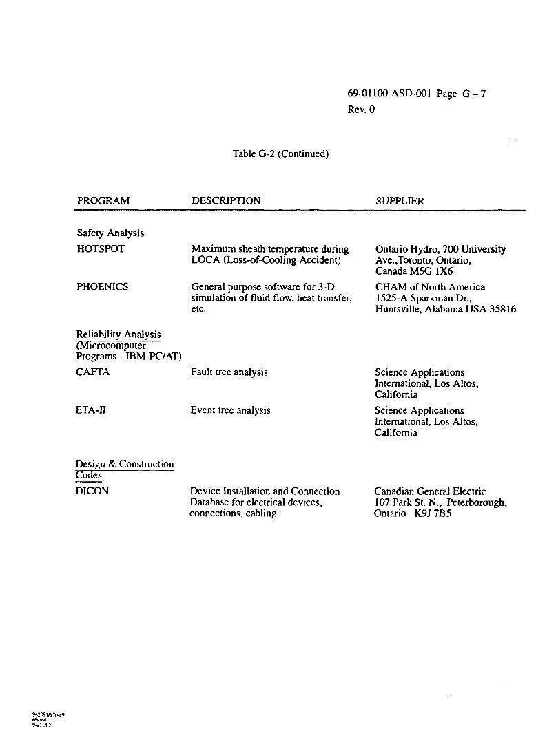
69-01100-ASD-001 Page G - 7
Rev. 0
Table G-2 (Continued)
PROGRAM DESCRIPTION SUPPLIER
Safety Analysis
HOTSPOT
PHOENICS
Maximum sheath temperature duringLOCA (Loss-of-Cooling Accident)
General purpose software for 3-Dsimulation of fluid flow, heat transfer,etc.
Ontario Hydro, 700 UniversityAve.,Toronto, Ontario,Canada M5G 1X6
CHAM of North America1525-A Sparkman Dr.,Huntsville, Alabama USA 35816
Reliability Analysis(MicrocomputerPrograms - IBM-PC/AT)
CAFTA
ETA-II
Fault tree analysis
Event tree analysis
Science ApplicationsInternational, Los Altos,California
Science ApplicationsInternational, Los Altos,California
Design & ConstructionCodes
DICON Device Installation and ConnectionDatabase for electrical devices,connections, cabling
Canadian General Electric107 Park St. N., Peterborough,Ontario K9J 7B5
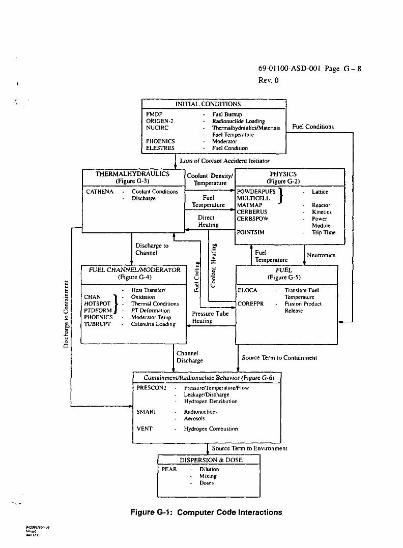
69-01100-ASD-001 Page G - 8
Rev. 0
INITIAL CONDITIONS
FMDPORIGEN-2NUCIRC
PHOENICSELESTRES
Fuel BumupRadionuclide LoadingThermalhydraulics/MaterialsFuel TemperatureModeratorFuel Condition
Fuel Conditions
Loss of Coolant Accident Initiator
a
THERMALHYDRAULICS(Figure G-3)
CATHENA Coolant ConditionsDischarge
Coolant Density/Temperature
FuelTemperature
DirectHeating
Discharge toChannel
FUEL CHANNEL/MODERATOR(Figure G-4)
CHAN "]HOTSPOTPTDFORM JPHOENICSTUBRUPT
Heat Transfer/OxidationThermal ConditionsPT DeformationModerator Temp.Calandria Loadine
u
BO
U
PHYSICS(Figure G-2)
POWDERPUFSMULT1CELLMATMAPCERBERUSCERBSPOW
PO1NTSIM
Lattice
ReactorKineticsPowerModuleTrip Time
Pressure TubeHeating
FuelTemperature
Neutronics
FUEL(Figure G-5)
ELOCA
COREFPR
Transient FuelTemperatureFission ProductRelease
ChannelDischarge Source Term to Containment
Containment/Radionuclide Behavior (Figure G-6)
PRESCON2 - Pressure/Temperature/FlowLeakage/DischargeHydrogen Distribution
SMART - RadionuclidesAerosols
VENT - Hydrogen Combustion
Source Term to Environment
DISPERSION & DOSEPEAR Dilution
MixingDoses
Figure G-1: Computer Code Interactions
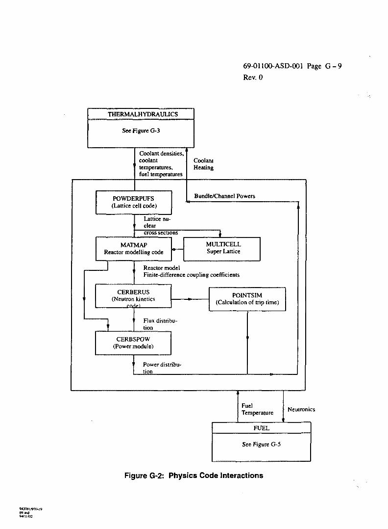
69-01100-ASD-001 Page G - 9
Rev. 0
THERMALHYDRAUUCS
See Figure G-3
Coolant densities,coolanttemperatures,fuel temperatures
POWDERPUFS(Lattice cell code)
CoolantHeating
Bundle/Channel Powers
Lattice nu-clearcross sections
MATMAPReactor modelling code
MULTICELLSuper Lattice
, Reactor modelFinite-difference coupling coefficients
CERBERUS(Neutron kinetics
POINTSIM(Calculation of trip time)
Flux distribu-tion
CERBSPOW(Power module)
Power distribu-tion
FuelTemperature
Neutronics
FUEL
See Figure G-5
Figure G-2: Physics Code Interactions
W2O»l/»7«-c969-»dW1I/O2
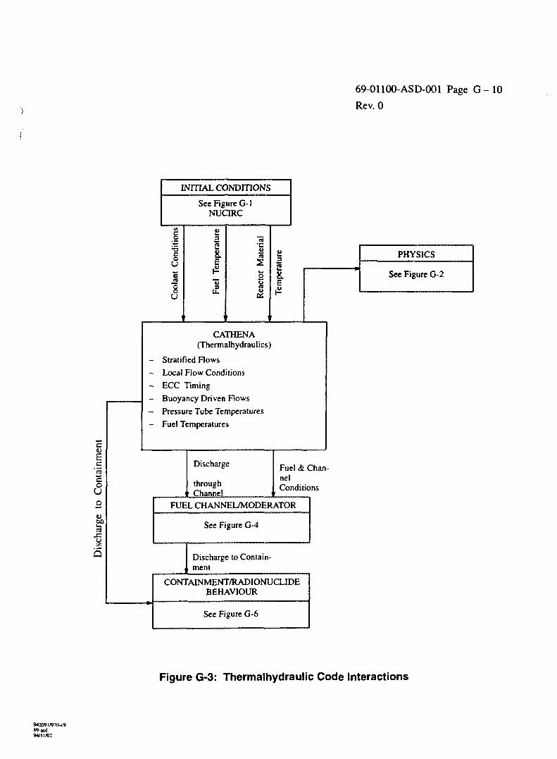
69-01100-ASD-001 Page G - 1 0
Rev. 0
INITIAL CONDITIONS
See Figure G-lNUCIRC
c
tio
ondi
Uc
gU
\
w
c3
Con
t
o
u
1°xzu
Q
a3cs28.1
"u3
.2
late
r;o
r N
SOi
ure
pera
tE
PHYSICS
See Figure G-2
CATHENA(Thermalhydraulics)
- Stratified Flows
- Local Flow Conditions
- ECC Timing
- Buoyancy Driven Flows
- Pressure Tube Temperatures
- Fuel Temperatures
Discharge
throughChannel
Fuel & Chan-nelConditions
FUEL CHANNEL/MODERATOR
See Figure G-4
Discharge to Contain-ment
CONTAINMENT/RADIONUCLIDEBEHAVIOUR
See Figure G-6
Figure G-3: Thermalhydrauiic Code Interactions
69-asil94/1 ] /«:
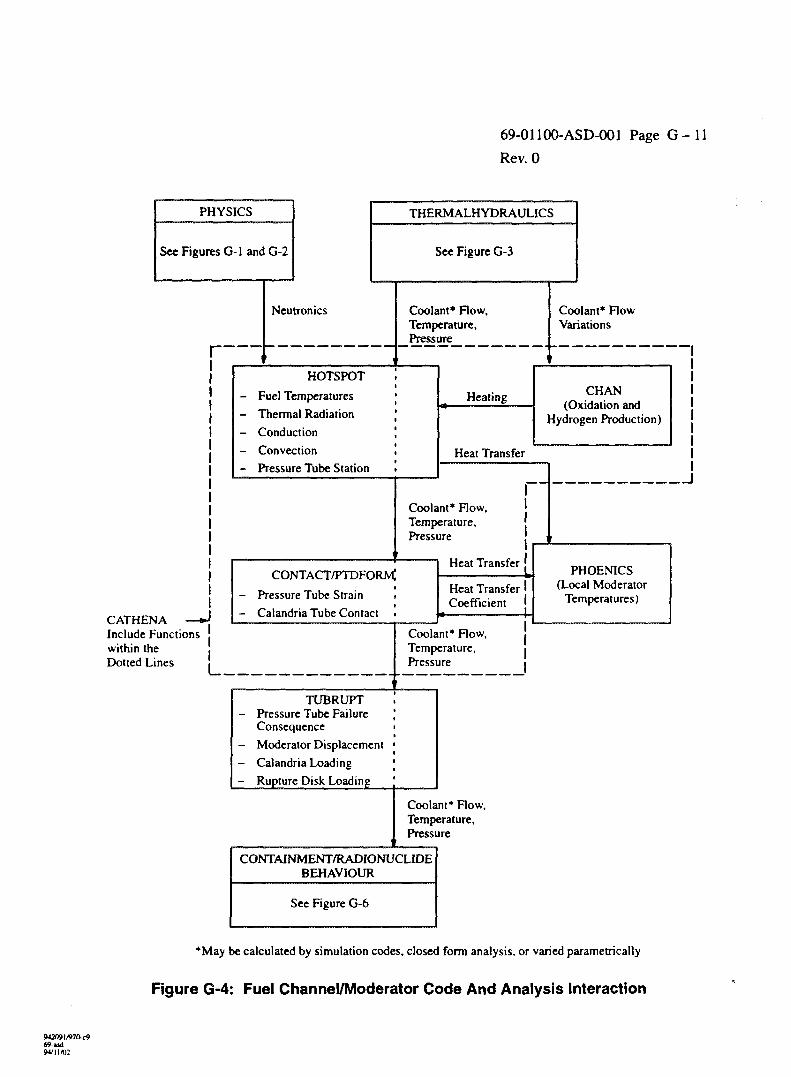
69-01100-ASD-001 Page G - l l
Rev. 0
PHYSICS
See Figures G-1 and G-2
CATHENAInclude Functionswithin theDotted Lines L.
THERMALHYDRAULICS
See Figure G-3
Neutronics Coolant* Flow,Temperature,Pressure
HOTSPOT
Fuel Temperatures
Thermal Radiation
Conduction
Convection
Pressure Tube Station
Heating
Heat Transfer
Coolant* Flow,Temperature,Pressure
CONTACT/PTDFORM;
- Pressure Tube Strain ,
- Calandria Tube Contact •
Heat Transfer
Heat TransferCoefficient
Coolant* Flow,Temperature,Pressure
TUBRUPT- Pressure Tube Failure
Consequence- Moderator Displacement- Calandria Loading
- Rupture Disk Loading
Coolant* Flow,Temperature,Pressure
CONTAINMENT/RADIONUCLIDEBEHAVIOUR
See Figure G-6
Coolant* FlowVariations
CHAN(Oxidation and
Hydrogen Production)
PHOEN1CS(Local Moderator
Temperatures)
*May be calculated by simulation codes, closed form analysis, or varied parametrically
Figure G-4: Fuel Channel/Moderator Code And Analysis Interaction
69-udM/1IA12
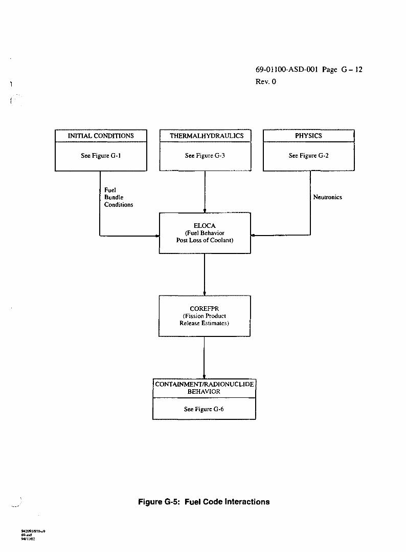
69-01100-ASD-001 Page G-12
Rev. 0
INITIAL CONDITIONS
See Figure G-l
THERMALHYDRAULICS
See Figure G-3
FuelBundleConditions
PHYSICS
See Figure G-2
ELOCA(Fuel Behavior
Post Loss of Coolant)
Neutronics
COREFPR(Fission Product
Release Estimates)
CONTA1NMENT/RADIONUCLIDEBEHAVIOR
See Figure G-6
Figure G-5: Fuel Code Interactions
M2O»I/»7O<9
94/1 Ml
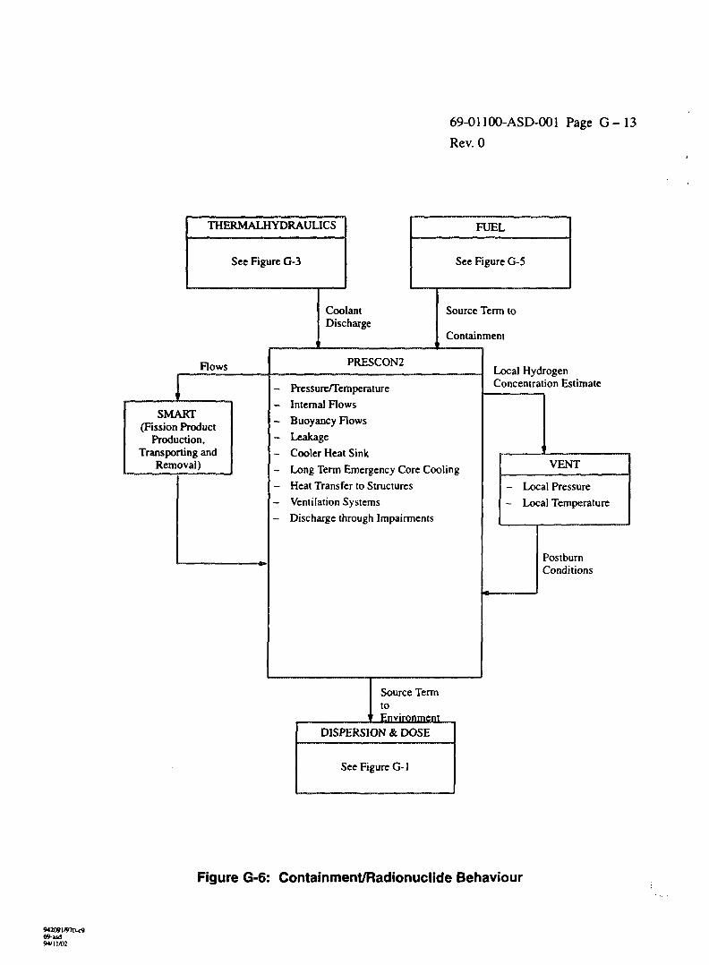
69-01100-ASD-001 Page G - 1 3
Rev. 0
THERMALHYDRAULICS
See Figure G-3
Flows
SMART(Fission Product
Production,Transrjortino and
Removal)
FUEL
See Figure G-5
CoolantDischarge
Source Term to
Containment
PRESCON2
- Pressure/Temperature
- Internal Flows
- Buoyancy Flows
- Leakage
- Long Term Emergency Core CoolinE
- Heat Transfer to Structures
- Ventilation Systems
- Discharge through Impairments
Source TenrtoEnvironmen
Local HydrogenConcentration Estimate
i
VENT
- Local Pressure
- Local Temperature
PostburnCondi tions
t
DISPERSION & DOSE
See Figure G-l
Figure G-6: Containment/Radionuclide Behaviour
69-ud94/11/02
T*€ AM? m ' lo
ll
10••»•
x i ••:'»
I M>fC1
I . . .J L
L »u» • i • : t
. J I J
! * • - • • ' .
'.Mat."
v «•••;••«»
OI J
« ' . » ! • > »
e«"» no*
mo r«t» f
4.0-»
CO«PyPTEft-AIO€O ENGINEERING <CAE> TASKS« A C5»OO PLANT UTE-CYCLC
POOR QUALITY IORIGINAL
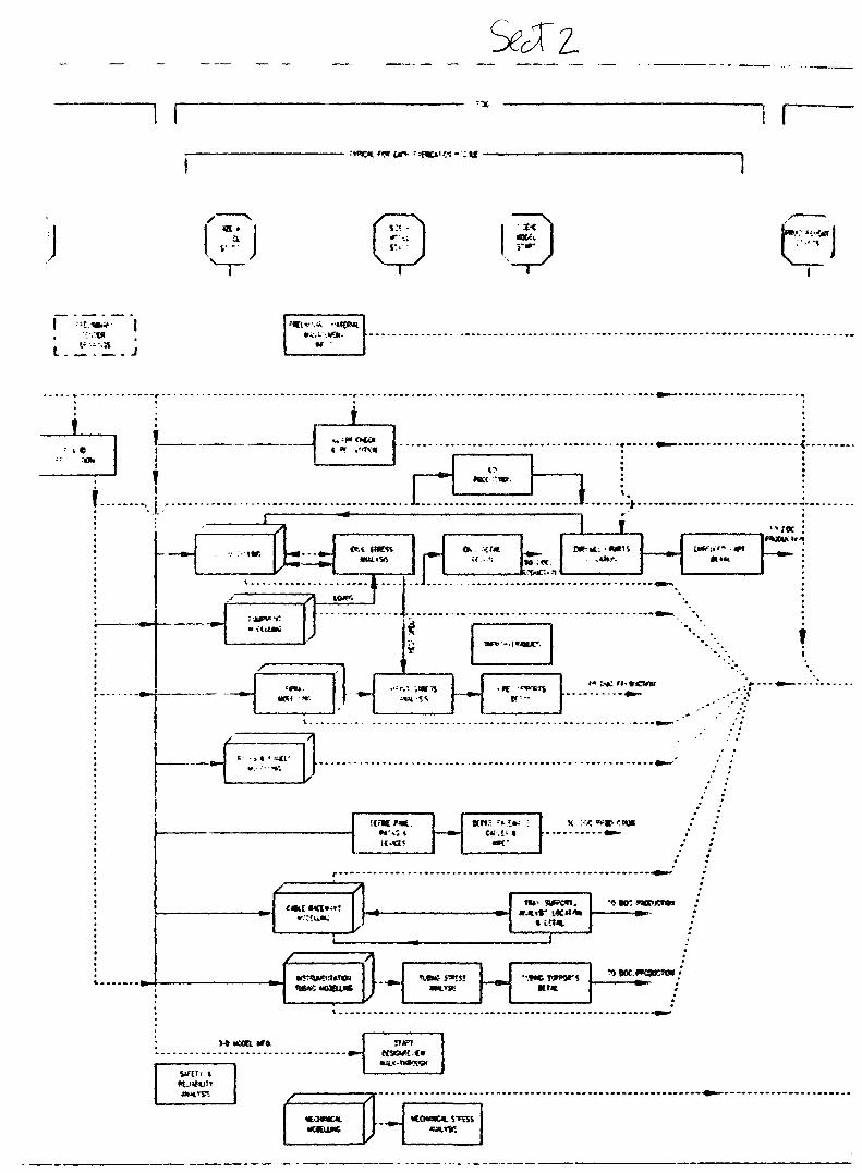
.:". - ; U
I I
1
i.Jiii.J
vM0Ml
u»n I
»•••
»«:»-,
x :-•<•»»•«: i
M i r wc«i»
H lit*
<rac
(KOWKILXCOEUMC H
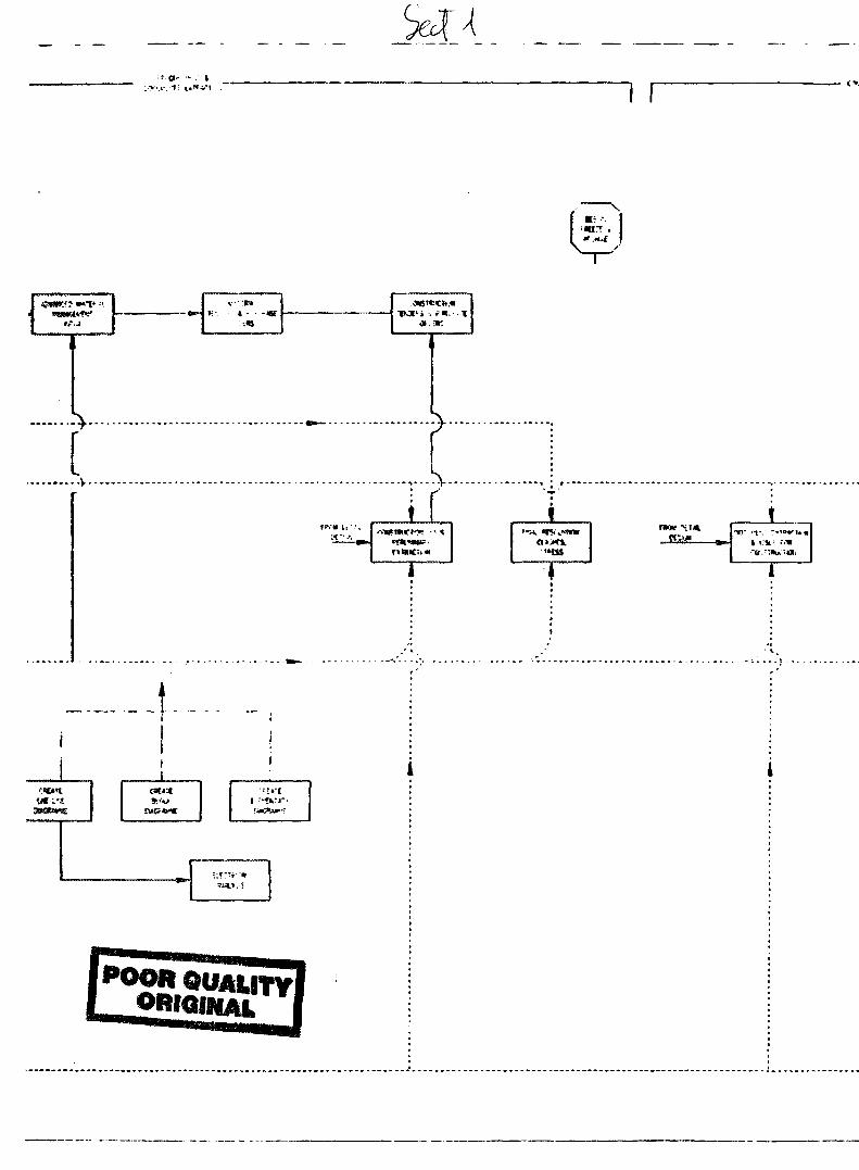
I f
•V
ONS«
» .
1
I
:<-•>;
ifo«xv
'HSS •<t.
•:«t»'ti ••»»:«-
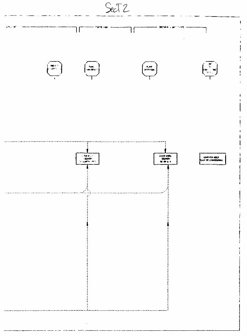
BOMK5
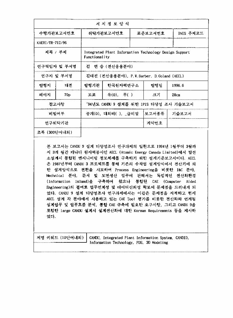
IMS
KAERI/TR-712/96
Integrated Plant Information Technology Design SupportFunctionality
), p. w. Barber, D.Goland (AECL)
1996.6
70p -fi-(O), -?-( ) 28cm
'94V1S. CANDU 9 IPIS
^ CANDU 9 ^Tfl
371)1994<d 1^-?-^
(Atomic Energy Canada L i m i t e d ) ^ ^
A|olcK AECL
CANDU 3
A | £ * M Process Engineering I&CMechnical ^o>, ^ ^
(Information Island)
Engineering)^
}. CANDU 9
-a7|| 4
CAE (Computer Aided
large CANDU
Sd-b CAE Tool
CAE ̂ H l ̂ A ? > Jfi-̂ -A}*o>( - L e U CANDU
Korean Requirements -§-§• f̂l
CANDU, Integrated Plant Information System, CANDID,Information Technology, PDS, 3D Modeling
BIBLIOGRAPHIC INFORMATION SHEET
Performing Org.Report No.
Sponsoring Org.Report No.
Standard ReportNo.
INIS SubjectCode
KAERI/TR-712/96
Title / Subtitle Integrated Plant Information Technology Design SupportFunctionality
Project Manager & Dept Kim, Yeon-Seung (Computer Applications Department)
Researcher and Dept. Kim, Dae-Jin(CA), P.W.Barber, D.Goland (AECL)
Pub. Place Taejon Pub. Org. KAERI Pub. Date 1996.6
Page 70p Fig. /Tab. Yes(O), No( ) Size 28cm
Note '94 CANDU 9 Feasibility Study IPIS Report
Classified Open(O), Outside( ), _Class Report Type Technical Report
Sponsoring Org. Contract No
Abstract( 300 Words)
This technical report was written as a result of Integrated PlantInformation System (IPIS) feasibility study on CANDU 9 project which hadbeen carried out from January, 1994 to March, 1994 at AECL (Atomic EnergyCanada Limited) in Canada. From 1987, AECL had done endeavour to changeengineering work process from paper based work process to computer basedwork process through CANDU 3 project. Even though AECL had a lot of goodresults from computerizing the Process Engineering, Instrumentation Controland Electrical Engineering, Mechnical Engineering, Computer Aided Design andDrafting, and Document Management System, but there remains the problem ofinformation isolation and integration. On this feasibility study, IPISdesign support functionality guideline was suggested by evaluating currentAECL CAE tools, analyzing computer aided engineering task and workflow,investigating request for implementing integrated computer aided engineeringand describing Korean request for future CANDU design including CANDU 9.
Keywords(Within 10 Words) CANDU, Integrated Plant Information System, CANDID,Information Technology, PDS, 3D Modeling
- li -