Embed Size (px)
Citation preview
Leader in Audio Engineering
KAV-250aStereo Power Amplifier
KAV-250a/3Three-Channel Power Amplifier
Instructions for Use, v 99.2
Owner’s Reference
KAV-250a Stereo Power Amplifier and
KAV-250a/3 Three-Channel Power Amplifier
Instructions for Use, v 99.2Cover: KAV-250a/3 Three-Channel Power Amplifier
Krell Industries, Inc.45 Connair RoadOrange, CT 06477-3650 USA
TEL 203-799-9954
FAX 203-799-9796
E-MAIL krell @ krellonline.comWEBSITE http://www.krellonline.com
This product complies with the EMC directive (89/336/EEC) and the low-voltage directive(73/23/EEC).
WARNINGSThe amplifier must be placed on a firm, level surface where it is not exposed to dripping orsplashing.
The ventilation grids on the top of the amplifier and the space underneath the amplifier must beunobstructed at all times during operation. Do not place flammable material above or beneaththe amplifier.
Contact your authorized Krell dealer, distributor, or Krell before using any devices designed toalter or stabilize the AC power for the KA V-250a or KA V-250a/3.
Before connecting the KA V-250a or KA V-250a/3, make sure the amplifier is off and any outputdevice (such as a preamplifier) is in mute or stand-by mode. Make sure all cable terminationsare of the highest quality and free from frayed ends, short circuits, or cold solder joints.
Use only one set of inputs to the amplifier at a time.
After reconfiguring for MAT, do not use more than one input at the same time.
After bridging, do not use both inputs at the same time.
THERE ARE NO USER SERVICEABLE PARTS INSIDE ANY KRELL PRODUCTPlease contact your authorized Krell dealer, distributor, or Krell if you have any questions notaddressed in this reference manual.
This product is manufactured in the United States of America. Krell® is a registered trademark of KrellIndustries, Inc., and is restricted for use by Krell Industries, Inc., its subsidiaries, and authorized agents.Multi Amp ThroughputTM is a trademark of Krell Industries, Inc. All other trademarks and tradenames areregistered to their respective companies.
© 1999 by Krell Industries, Inc. All rights reserved P/N: I960101710688
Contents
INTRODUCTION ’
DEFINITION OF TERMS
UNPACKING
PLACEMENT
AC Power Guidelines
FRONT PANEL DESCRIPTION: KAV-250a
BACK PANEL DESCRIPTION: KAV-250a
FRONT PANEL DESCRIPTION: KAV-250a/3
BACK PANEL DESCRIPTION: KAV-250a/3
CONNECTING THE KAV-250a or KAV-250aJ3 AMPLIFIER
TO YOUR SYSTEM
Input and Output Connections
OPTIONAL SYSTEM CONFIGURATIONS
Multi Amp Throughput
Bridged Operation
Examples of Connection Scenarios
AMPLIFIER OPERATION
On/Off and Operation
AMPLIFIER TROUBLESHOOTING
How to Troubleshoot System Noise
QUESTION AND ANSWER
WARRANTY
RETURN AUTHORIZATION PROCEDURE
SPECIFICATIONS
Page
1
1
2
3
3
5
7
10
12
14
14
15
15
20
22
25
25
26
26
27
28
29
30
KAV-250a and KAV-250a/3 Amplifiers iii
Illustrations
FIGURE 1
FIGURE 2
FIGURE 3
FIGURE 4
FIGURE 5
The KAV-250a Front Panel
The KAV-250a Back Panel
The KAV-250a/3 Front Panel
The KAV-250a/3 Back Panel
Reconfiguring the KAV-250a for MAT
or Bridged Operation
FIGURE 6 Reconfiguring the KAV-250a/3 for MAT
or Bridged Operation
Page
4
6
9
11
16
19
iv KAV-250a and KAV-250a/3 Amplifiers
IntroductionThank you for your purchase of the Krell KAV-250a Stereo Power Amplifier orKAV-250a/3 Three-Channel Power Amplifier..
The KAV-250a and KAV-250aJ3 amplifiers provide substantial two- and three-channeloutput power that delivers realistic music production at an exceptional value. Theseamplifiers can be customized with a variety of optional system configurations: MultiAmp Throughput (MAT), bridged operation, and high power mono operation. Theseoptions provide a wider range of power outputs and connection options. Both the KAV-250a and KAV-250a/3 amplifiers provide balanced and single-ended inputs forcomplete compatibility with other components. The KAV-250a and KAV-250a/3amplifiers can be operated using the 12 VDC trigger for other components. Eitheramplifier integrates seamlessly home theater or whole-house systems.
This reference manual contains important information on placement, installation, andoperation of the KAV-250a and KAV-250a/3 amplifiers. Please read this informationcarefully. A thorough understanding of these details helps ensure satisfactory operationand long life for your KAV-250a or KAV-250aJ3 amplifier and related systemcomponents.
Definition of TermsMulti Amp ThroughputAn internal connection option that sends the same music signal to all amplifier channelsusing one balanced or single-ended connection. MAT reduces installation complexityand cabling requirements in systems containing multiple amplifiers. MAT also allows avariety of connection scenarios, including powering loudspeakers that have two sets ofbinding posts and independently powering multiple pairs of stereo loudspeakers toextend the listening environment throughout your home.
BridgingAn internal connection option that links two amplifier channels to operate as onecombined amplifier channel, greatly increasing the channel’s power output.
OnWhen the power button on the front panel is pressed and the blue power LEDilluminates, the amplifier is on and ready to play music.
OffWhen the power button on the front panel is pressed and the blue power LED turns off,the amplifier is off.
KAV-250a and KAV-250a/3 Amplifiers 1
Unpacking
Open the shipping box, which contains:1 amplifier unit (packed in foam end-caps)2 ribbon connection cablesKAV-250a fuses:
2 AGC-8 (~ ’amp)1 slow-blow (20 amp for 100/120 V or 12 amp for 220/240 V)or
KAV-250a/3 fuses:3 AGC-.8 ~ amp)1 slow-blow (20 amp for 100/120 V or 12 amp for 220/240 V)
1 12 VDC output (12 V trigger) cable1 IEC connector (AC power) cord1 T-15 Torx wrench1 packet containing the owner’s reference manual and the warranty registrationcard.
Grasp the underside of the foam end-caps that encase the amplifier and lift theamplifier straight out of the shipping box.
Place the amplifier in a safe location and remove the protective plastic wrapping.
NotesIf any of these items are not included in the shipping box, please contact yourauthorized Krell dealer, distributor, or Krell for assistance.Save all packing materials. If you ship your amplifier in the future, repack the unit in itsoriginal packaging to prevent trans# damage. See Return Authorization Procedure,on page 29, for more information.
2 KAV-250a and KAV-250aJ3 Amplifiers
Placement
Before you integrate the KAV-250a or KAV-250a/3 into your system, review thefollowing guidelines to choose the location for the component. This will facilitate aclean, trouble-free installation.
The KAV-250a and KAV-250aJ3 require at least two inches (5 cm) of clearance each side and at least two inches (5 cm) of clearance above the component to provideadequate ventilation.
Your amplifier does not require any type of special rack or cabinet for installation. Forthe dimensions of your amplifier see Specifications, on pages 30 and 31.
Place the amplifier as close to the loudspeakers as possible and keep the speakercable length to a minimum. Speaker cable adds impedance to the load the amplifiermust drive, regardless of the cable’s gauge. Krell amplifiers drive the lowestimpedances with ease, but long speaker cables reduce the maximum power that isdelivered to the loudspeakers.
AC POWER GUIDELINESKrell recommends operating each amplifier from a dedicated 15-amp AC power line.For maximum power output, operate the KAV-250a or KAV-250a/3 amplifier from adedicated 20-amp AC power line.
KAV-250a and KAV-250a/3 Amplifiers 3
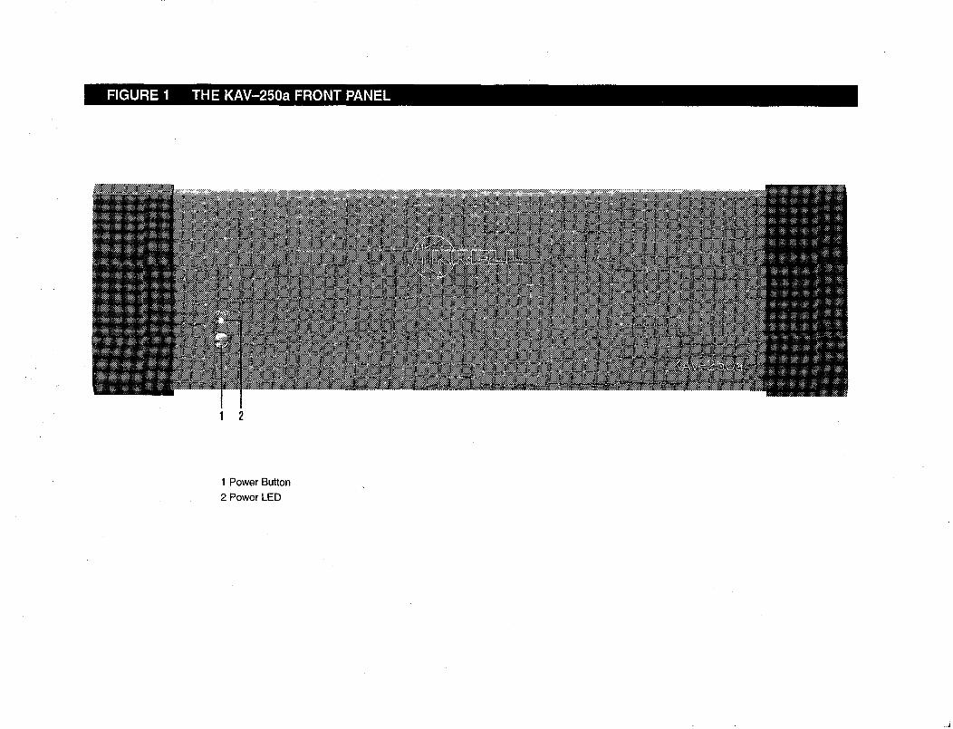
FIGURE 1 THE KAV-250a FRONT PANEL
1 2
1 Power Button2 Power LED
Front Panel Description: KAV-250a
See Figure 1 on page 4
1 Power ButtonUse this button to turn the KAV-250a power on and off and also to switch the 12 VDCoutput (12 V trigger) on and off.2 Power LEDThe blue power LED illuminates when the amplifier is on.
KAV-250a and KAV-250a/3 Amplifiers 5
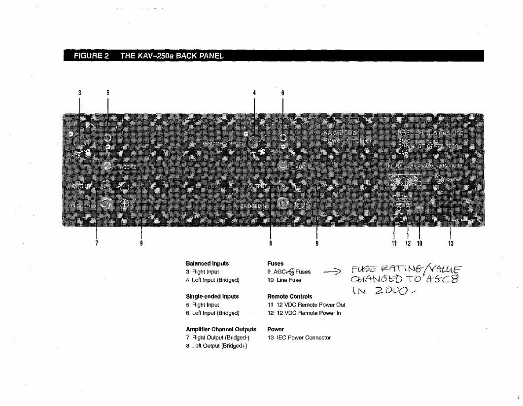
FIGURE 2 THE KAV-250a BA(;K PANEL
5
11 12 10 13
Balanced Inputs3 Right Input4 Left Input (Bridged)
Single-ended Inputs5 Right Input6 Left Input (Bridged)
Amplifier Channel Outputs7 Right Output (Bridged-)
8 Left Output (Bridged+)
Fuses9 AGC~ Fuses10 Line Fuse
Remote Controls11 12 VDC Remote Power Out12 12 VDC Remote Power In
Power13 IEC Power Connector
Back Panel Description: KAV-250a
See Figure 2 on page 6
The KAV-250a back panel provides connections for all inputs and outputs, remotecontrol input and output links, and AC power supply. Inputs and outputs labeled left andright are on the left and right side of the amplifier, respectively, when viewing theamplifier from the front panel.
Balanced Inputs
3, 4 InputsThese are the right (3) and the left (4) KAV-250a channel inputs for output devices balanced XLR connectors.
Single-ended Inputs5,6 InputsThese are the right (5) and the left (6) KAV-250a channel inputs for output devices single-ended RCA connectors.The left balanced or single-ended inputs are used for bridged operation. SeeReconfiguring the KA V-250a for Bridged Operation, on page 20.
Amplifier Channel Outputs7 Output Bridged(-)8 Output Bridged(+)These are the right (7) and left (8) KAV-250a amplifier channel outputs with five-wayloudspeaker binding posts. The loudspeaker binding post terminals accept spade lugs,bare wire, banana plugs, or pins. Use the red terminal for the positive connection andthe black terminal for the.negative connection. For information on loudspeakerconnections for bridged operation, see Reconfiguring the lEA V-250a for BridgedOperation, on page 20.
Fuses9 AGC-12 FusesThe AGC 12 Volt loudspeaker fuses protect the KAV-250a against short circuits inloudspeaker output.10 Line FuseThe line fuse protects the KAV-250a against short circuits in internal power supplies.
NoteFuses must be replaced with the fuse value specified on the KA V-250a back panel. Usea 20 amp slow-blow line fuse for 100/120 V systems or a 12 amp slow-blow line fuse for220/240 V systems.
KAV-250a and KAV-250a/3 Amplifiers 7
Back Panel Description, continued
Remote Controls11 12 VDC Remote Power Out12 12 VDC Remote Power InThe KAV-250a is equipped with an output that sends 12 VDC power on/off (12 trigger) signals to other Krell components and other devices that incorporate 12 V trigger. This allows you to turn the KAV-250a on and off using a Krell or othercomponent in a custom installation.
Notes12 VDC Out/in (12 V trigger) remote power is limited to 30 ma.Consult the owner’s manual of any component used in a custom installation to take fulladvantage of the KA V-250a remote capability.
Power Supply13 IEC ConnectorThe KAV-250a is equipped with a standard female IEC power connector, for use withthe provided AC power cord,
8 KAV-250a and KAV-250a/3 Amplifiers
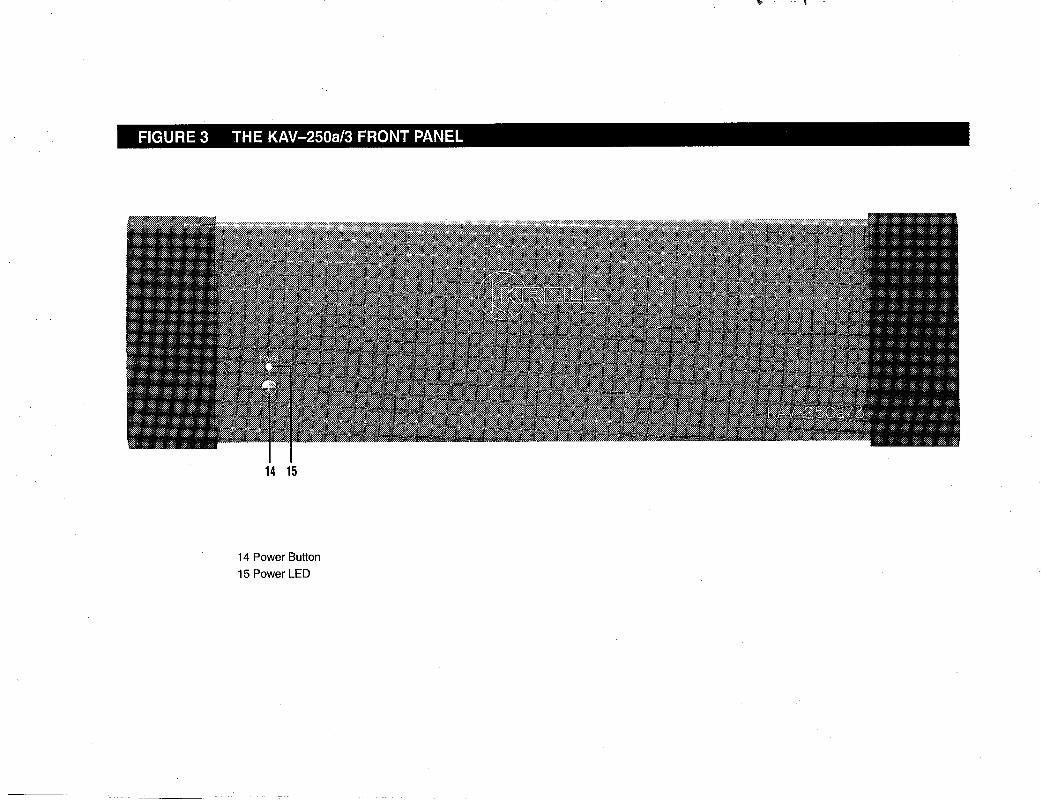
FIGURE 3 THE KAV-250a/3 FRONT PANEL
14 15
14 Power Button15 Power LED
Front Panel Description: KAV-250a/3
See Figure 3 on page 9
14 Power ButtonUse this button to turn the KAV-250a/3 power on and off and also to switch the 12 VDCoutput (12 V trigger) on and off.15 Power LEDThe blue power LED illuminates when the amplifier is powered on.
10 KAV-250a and KAV-250a/3 Amplifiers
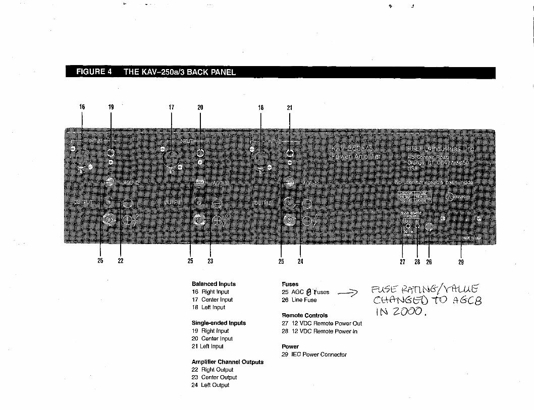
FIGURE 4 THE KAV-250a/3 BACK PANEL
16 19 17 2o 18 21
25 22 25 23 25 24 27 28 26 29
Balanced Inputs16 Right Input17 Center Input18 Left Input
Single-ended Inputs19 Right Input20 Center Input21 Left Input
Amplifier Channel Outputs22 Right Output23 Center Output24 Left Output
Fuses25 AGC e~Euses ~-----’~26 Line Fuse
Remote Controls27 12 VDC Remote Power Out28 12 VDC Remote Power tn
Power29 IEC Power Connector
ZOO0.
Back Panel Description: KAV-250a/3
See Figure 4 on page 11
The KAV-250a/3 back panel provides connections for all inputs and outputs, remotecontrol input and output links, and AC power supply. Inputs and outputs labeled left andright are on the left and right side of the amplifier, respectively, when viewing theamplifier from the front panel.
Balanced Inputs16, 17, 18 InputsThese are the right (16), center (17), and left (18) KAV-250a/3 channe~ inputs output devices with balanced XLR connectors.
Single-ended Inputs19, 20, 21 InputsThese are the right (19), center (20), and left (21) KAV-250a/3 channel inputs output devices with single-ended RCA connectors.
Amplifier Channel Outputs22, 23, 24 OutputsThese are the right (22), center (23), and left (24) KAV-250a/3 amplifier channeloutputs with five-way loudspeaker binding posts. The loudspeaker binding postterminals accept spade lugs, bare wire, banana plugs, or pins. Use the red terminal forthe positive connection and the black terminal for the negative connection. Forinformation about loudspeaker connections for bridged operation, see Reconfiguringthe KA V-250aJ’3 for Bridged Operation, on page 21.
Fuses25 AGC-12 FusesThe AGC 12 Volt loudspeaker fuses protect the KAV-250a/3 against short circuits inloudspeaker output.26 Line FuseThe line fuse protects the KAV-250a/3 against short circuits in internal power supplies.
12 KAV-250a and KAV-250aJ3 Amplifiers
Back Panel Description, continued
NoteFuses must be replaced with the fuse value specified on the KA V-250a/3 back panelUse a 20 amp slow-blow line fuse for 100/120 V systems or a 12 amp slow-blow linefuse for 220/240 V systems.
Remote Controls27 12 VDC Remote Power Out28 12 VDC Remote Power InThe KAV-250a/3 is equipped with an output that sends 12 VDC power on/off (12 trigger) signals to other Krell components and other devices that incorporate 12 V trigger. This allows you to turn the KAV-250aJ3 on and off using a Krell or othercomponent in a custom installation.
Notes12 VDC Out/In (12 V trigger) remote power is limited to 30 ma.
Consult the owner’s manual of each component used in a custom installation to take fulladvantage of the KA V-250a/3 remote capability.
Power Supply29 IEC Power ConnectorThe KAV-250a/3 is equipped with a standard female IEC power connector, for use withthe provided AC power cord.
KAV-250a and KAV-250a/3 Amplifiers 13
Connecting the KAV-250a or KAV-250a/3Amplifier to Your System
INPUT AND OUTPUT CONNECTIONS
The following steps describe how to connect cables to the KAV-250a or KAV-250a/3amplifier.
1. Neatly arrange and organize the wiring to and from the amplifier and allcomponents. Separate AC wires from audio cables to prevent hum or otherunwanted noise from being introduced into the system.
21 Connect the loudspeaker cables to the KAV-250a amplifier channel output speakerbinding posts (7, 8), or the KAV-250a/3 amplifier channel output speaker bindingposts (22, 23, 24) located on their respective back panels.
The amplifier channel outputs for the KAV-250a and KAV-250a/3 use five-wayloudspeaker binding posts. The loudspeaker binding post terminals accept spadelugs, bare wire, banana plugs, or pins. Use the red terminal for the positiveconnection and the black terminal for the negative connection.
3. Connect the interconnect cables from your output device to the amplifier inputs. TheKAV-250a is equipped with balanced (3, 4) or single-ended (5, 6) inputs and KAV-250a/3 is equipped with balanced (16, 17, 18) or single-ended (19, 20, inputs located on their respective back panels. The balanced inputs use three-pinXLR connectors; the single-ended inputs use RCA connectors.
4. Insert the end of the AC power cord into the IEC power connector on the KAV-250a(13) or KAV-250a/3 (29) back panel. Insert the other end into the AC wall outlet.
The amplifier is now ready for operation. See Amplifier Operation, on page 25.
The KAV-250a or KAV-250a/3 amplifier is shipped with shorting pins in the XLRinputs. These pins should remain in the XLR inputs if the amplifier is operating in thesingle-ended mode. When the shorting pin is inserted, pins 1 and 3 are shortedtogether. Remove the shorting pins to connect the amplifier for balanced operation.The XLR pin configuration is described below:
Pin 1 GroundPin 2 Non-inverting (0°)
Pin 3 Inverting (180°)
Krell recommends using balanced interconnect cables. Balanced interconnect cablesnot only can minimize sonic loss but are also immune to induced noise, especially withinstallations using long cables. Balanced connections have 6 dB more gain than single-ended connections. When level matching is critical, keep this gain value in mind.
14 KAV-250a and KAV-250aJ3 Amplifiers
Optional System Configurations
The KAV-250a and KAV-250a/3 can be reconfigured for either Multi Amp Throughput(MAT) or bridged operation.
IMPORTANTRemoving the cover to reconfigure for MA T or for bridged operation is the ONL Yinstance you are authorized to remove the cover of ANY Kre// component withoutvoiding your Warranty. For more information on product/imitations and restrictions, seeWarranty, on page 28.
Before Reconfiguring for MAT or Bridged OperationRead the following important safety instructions before you attempt to reconfigure youramplifier for either MAT or bridged operation:
1. Unplug the power cord. Unplug the AC power cord from both the IEC powerconnector of the KAV-250a (13) or KAV-250aJ3 (29) on the back panel, and the AC outlet.
2. Avoid the power supply. After removing the screws (see instructions below) andthe cover, locate and stay aware of the location of the power supply. Avoid makingcontact with that area of the amplifier.
3. Remove jewelry. Rings, necklaces, bracelets, and other pieces of metal jewelrycan conduct an electrical charge. Consider removing them before attempting anyreconfiguration.
4. Always replace cover. Make sure the amplifier’s cover is properly replaced andsecured by the 12 screws before resuming operation.
IMPORTANTOperating the amplifier without the cover properly replaced and secured mayvoid your warranty.
MULTI AMP THROUGHPUTMulti Amp Throughput (MAT), an internal connection option for either the KAV-250a the KAV-250a/3, lets you send the same music signal to all amplifier channels usingone balanced or single-ended connection. MAT reduces installation complexity andcabling requirements in systems containing multiple amplifiers.
Inputs and outputs labeled left and right are on the left and right side of the amplifier,respectively, when viewing the amplifier from the front panel
KAV-250a and KAV-250a/3 Amplifiers 15
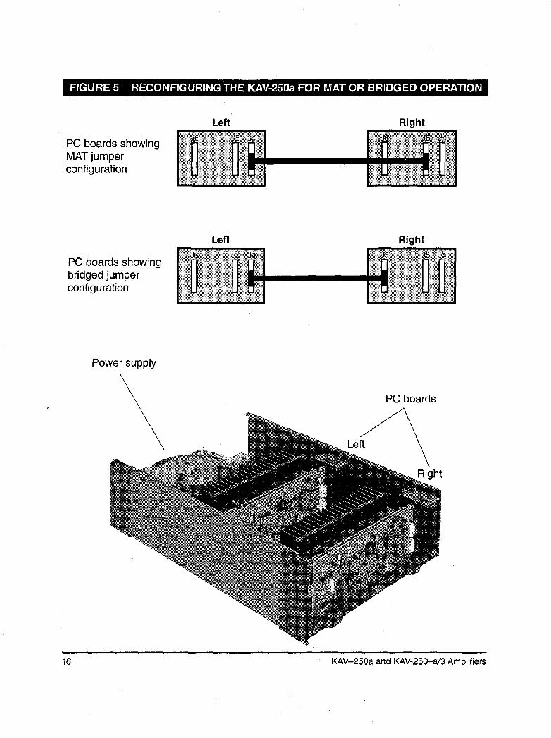
FIGURE 5 RECONFIGURING THE KAV-250a FOR MAT OR BRIDGED OPERATI( tN
PC boards showingMAT jumperconfiguration
Left Right
PC boards showingbridged jumperconfiguration
Left Right
Power supply
PC boards
Right
16 KAV-250a and KAV-250-a/3 Amplifiers
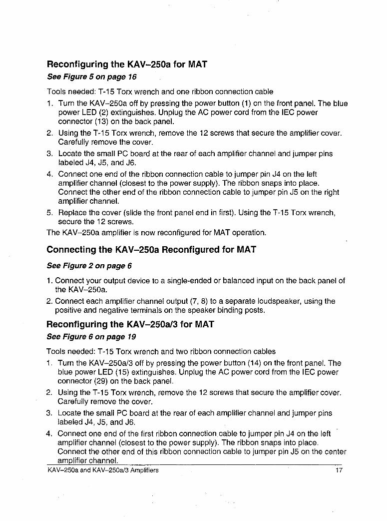
Reconfiguring the KAV-250a for MATSee Figure 5 on page 16
Tools needed: T-15 Torx wrench and one ribbon connection cable
1. Turn the KAV-250a off by pressing the power button (1) on the front panel. The bluepower LED (2) extinguishes. Unplug the AC power cord from the IEC powerconnector (13) on the back panel.
2. Using the T:15 Torx wrench, remove the 12 screws that secure the amplifier cover.Carefully remove the cover.
3. Locate the small PC board at the rear of each amplifier channel and jumper pinslabeled J4, J5, and J6.
4. Connect one end of the ribbon connection cable to jumper pin J4 on the leftamplifier channel (closest to the power supply). The ribbon snaps into place.Connect the other end of the ribbon connection cable to jumper pin J5 on the rightamplifier channel.
5. Replace the cover (slide the front panel end in first). Using the T-15 Torx wrench,secure the 12 screws.
The KAV-250a amplifier is now reconfigured for MAT operation.
Connecting the KAV-250a Reconfigured for MAT
See Figure 2 on page 6
1. Connect your output device to a single-ended or balanced input on the back panel ofthe KAV-250a.
2. Connect each amplifier channel output (7, 8) to a separate loudspeaker, using thepositive and negative terminals on the speaker binding posts.
Reconfiguring the KAV-250a/3 for MATSee Figure 6 on page 19
Tools needed: T-15 Torx wrench and two ribbon connection cables
1. Turn the KAV-250a/3 off by pressing the power button (14) on the front panel. Theblue power LED (15) extinguishes. Unplug the AC power cord from the IEC powerconnector (29) on the back panel.
2. Using the T-15 Torx wrench, remove the 12 screws that secure the amplifier cover.Carefully remove the cover.
3. Locate the small PC board at the rear of each amplifier channel and jumper pinslabeled J4, J5, and J6.
4. Connect one end of the first ribbon connection cable to jumper pin J4 on the leftamplifier channel (closest to the power supply). The ribbon snaps into place.Connect the other end of this ribbon connection cable to jumper pin J5 on the centeramplifier channel.
KAV-250a and KAV-250a/3 Amplifiers 17
5. Connect one end of the second ribbon connection cable to jumper pin J4 on thecenter amplifier channel. Connect the other end of this ribbon connection cable tojumper pin J5 on the right amplifier channel.
6. Replace the cover (slide the front panel end in first). Using the T-15 Torx wrench,secure the 12 screws.
The KAV-250a/3 amplifier is now reconfigured for MAT operation.
Connecting the KAV-250a/3 Reconfigured for MAT
See Figure 4 on page 11
1. Connect your output device to a single-ended or balanced input on the back panel ofthe KAV-250a/3.
2. Connect each amplifier channel output (22, 23, 24) to a separate loudspeaker, usingthe positive and negative terminals on the speaker binding posts.
18 KAV-250a and KAV-250a/3 Amplifiers
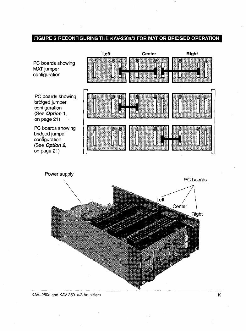
FIGURE 6 RECONFIGURING THE KAV-250a/3 FOR MAT OR BRIDGED OPERATION
PC boards showingMAT jumperconfiguration
PC boards showingbridged jumperconfiguration(See Option 1,on page 21)
PC boards showingbridged jumperconfiguration(See Option 2,on page 21)
Left Center Right
Power supplyPC boards
ht
KAV-250a and KAV-250-a/3 Amplifiers 19
BRIDGED OPERATION
The KAV-250a and the KAV-250a/3 can be reconfigured for bridged operation. Whenthe KAV-250a amplifier’s channels are bridged, the amplifier’s output power isquadrupled: the amplifier delivers 1,000 Watts to an 8 Ohm load. The KAV-250a/3 canbe reconfigured to bridge any two of its three amplifier channels to operate as onecombined amplifier channel. When using the bridged amplifier channel only, theKAV-250a/3 delivers 1,000 Watts to an 8 Ohm load.Inputs and outputs labeled left and right are on the left and right side of the amplifier,respectively, when viewing the amplifier from the front panel
Reconfiguring the KAV-250a for Bridged Operation
See Figure 5 on page 16
Tools needed: T-15 Torx wrench and one ribbon connection cable1. Turn the KAV-250a off by pressing the power button (1) on the front panel. The blue
power LED (2) extinguishes. Unplug the AC power cord from the IEC powerconnector (13) on the back panel.
2. Using the T-15 Torx wrench, remove the 12 screws that secure the amplifier cover.Carefully remove the cover.
3. Locate the small PC board at the rear of each amplifier channel and jumper pinslabeled J4, J5, and J6.
4. Connect one end of the ribbon connection cable to jumper pin J4 on the leftamplifier channel (closest to the power supply). The cable snaps into place. Connectthe other end of the ribbon connection cable to jumper pin J6 on the right amplifierchannel.
5. Replace cover (slide front panel end in first). Using the T-15 Torx wrench, securethe 12 screws.
The KAV-250a amplifier is now ready for bridged operation.
Connecting the Bridged KAV-250a
See Figure 2 on page 6
1. Connect the output cable from the output device to the balanced XLR (4/ or thesingle-ended RCA (6) inputs connectors marked (BRIDGED ~NPUT).
2. Connect the positive loudspeaker lead (red) to the positive binding post on the leftamplifier channel output (8), marked BRIDGED (+). Connect the negative loudspeakerlead (black) to the positive binding post on the right amplifier channel (7), markedBRIDGED (-).
20 KAV-250a and KAV-250a/3 Amplifiers
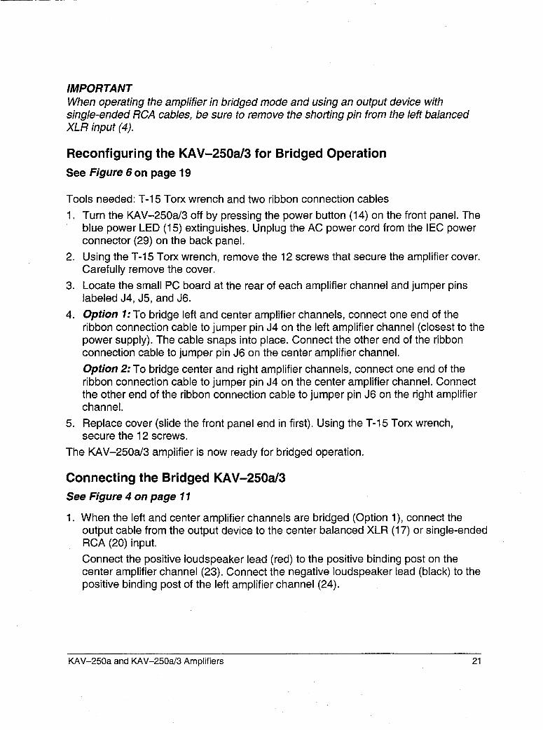
IMPORTANTWhen operating the amplifier in bridged mode and using an output device withsingle-ended RCA cables, be sure to remove the shorting pin from the/eft balancedXLR input (4).
Reconfiguring the KAV-250a/3 for Bridged OperationSee Figure 6 on page 19
Tools needed: T-15 Torx wrench and two ribbon connection cables1. Turn the KAV-250a/3 off by pressing the power button (14) on the front panel. The
blue power LED (15) extinguishes. Unplug the AC power cord from the IEC powerconnector (29) on the back panel.
2. Using the T-15 Torx wrench, remove the 12 screws that secure the amplifier cover.Carefully remove the cover.
3. Locate the small PC board at the rear of each amplifier channel and jumper pinslabeled J4, J5, and J6.
4. Option 1: To bridge left and center amplifier channels, connect one end of theribbon connection cable to jumper pin J4 on the left amplifier channel (closest to thepower supply). The cable snaps into place. Connect the other end of the ribbonconnection cable to jumper pin J6 on the center amplifier channel.Option 2: To bridge center and right amplifier channels, connect one end of theribbon connection cable to jumper pin J4 on the center amplifier channel. Connectthe other end of the ribbon connection cable to jumper pin J6 on the right amplifierchannel.
5. Replace cover (slide the front panel end in first). Using the T-15 Torx wrench,secure the 12 screws.
The KAV-250aJ3 amplifier is now ready for bridged operation.
Connecting the Bridged KAV-250a/3See Figure 4 on page 11
1. When the left and center amplifier channels are bridged (Option 1), connect theoutput cable from the output device to the center balanced XLR (17) or single-endedRCA (20) input.
Connect the positive loudspeaker lead (red) to the positive binding post on thecenter amplifier channel (23). Connect the negative loudspeaker lead (black) to positive binding post of the left amplifier channel (24).
KAV-250a and KAV-250a/3 Amplifiers 21
2. When the center and right amplifier channels are bridged (Option 2), connect theoutput cable from the output device to the right balanced XLR (16) or single-endedRCA (19)input.
Connect the positive loudspeaker lead (red) to the positive binding post on the(right) amplifier channel (22). Connect the negative loudspeaker lead (black) positive binding post of the center amplifier channel (23).The remaining channel may be connected for normal operation.
IMPORTANTWhen operating the amplifier in bridged mode and using an output device with asingle-ended RCA cable, be sure to remove the shorting pin from the balanced XLRinput.
EXAMPLES OF CONNECTION SCENARIOS
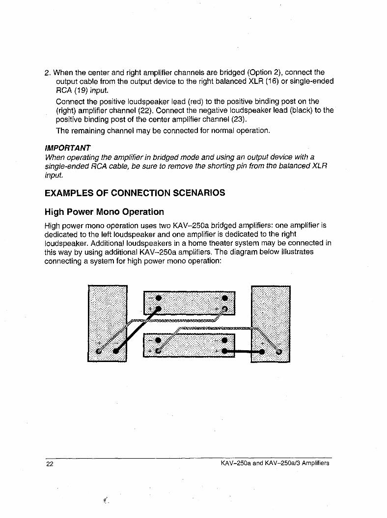
High Power Mono Operation
High power mono operation uses two KAV-250a bridged amplifiers: one amplifier isdedicated to the left loudspeaker and one amplifier is dedicated to the rightloudspeaker. Additional loudspeakers in a home theater system may be connected inthis way by using additional KAV-250a amplifiers. The diagram below illustratesconnecting a system for high power mono operation:
22 KAV-250a and KAV-250a/3 Amplifiers
Examples of Connection Scenarios, continued
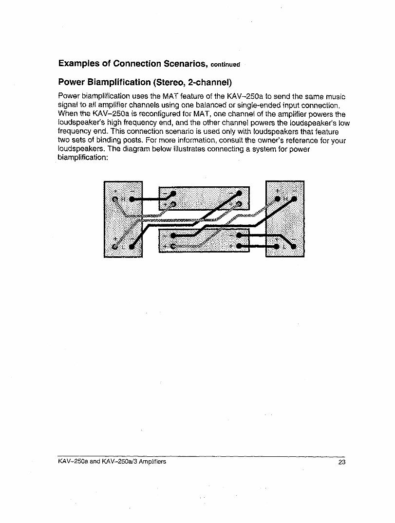
Power Biamplification (Stereo, 2-channel)
Power biamplification uses the MAT feature of the KAV-250a to send the same musicsignal to all amplifier channels using one balanced or single-ended input connection.When the KAV-250a is reconfigured for MAT, one channel of the amplifier powers theIoudspeaker’s high frequency end, and the other channel powers the Ioudspeaker’s lowfrequency end. This connection scenario is used only with loudspeakers that featuretwo sets of binding posts. For more information, consult the owner’s reference for yourloudspeakers. The diagram below illustrates connecting a system for powerbiamplification:
KAV-250a and KAV-250aJ’3 Amplifiers 23
Examples of Connection Scenarios, continued
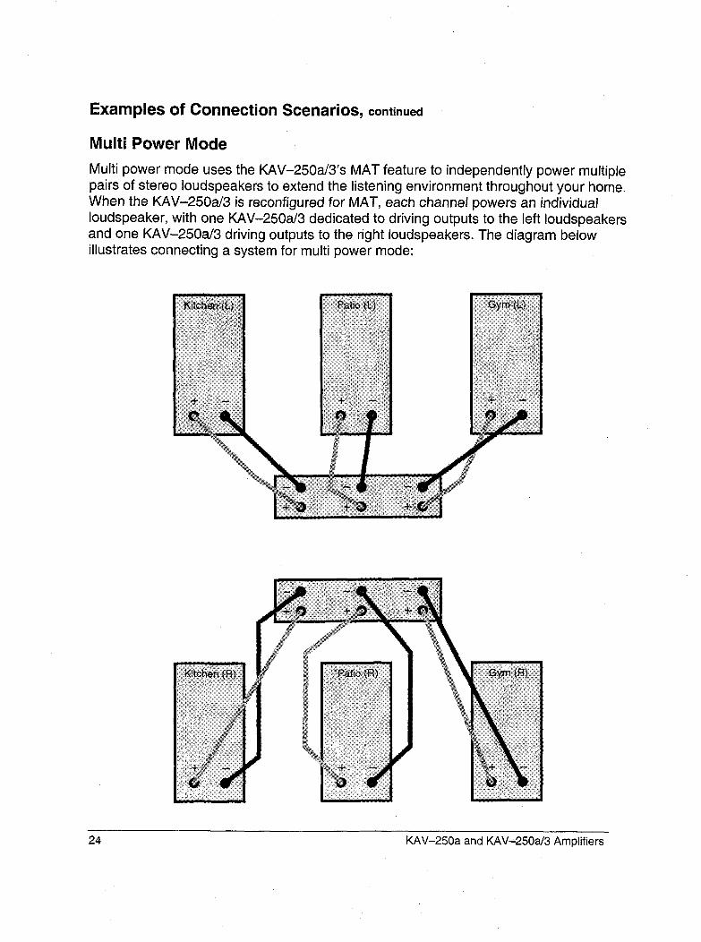
Multi Power Mode
Multi power mode uses the KAV-250a/3’s MAT feature to independently power multiplepairs of stereo loudspeakers to extend the listening environment throughout your home.When the KAV-250a/3 is reconfigured for MAT, each channel powers an individualloudspeaker, with one KAV-250a/3 dedicated to driving outputs to the left loudspeakersand one KAV-250a/3 driving outputs to the right loudspeakers. The diagram belowillustrates connecting a system for multi power mode:
24 KAV-250a and KAV-250aJ3 Amplifiers
Amplifier Operation
ON/OFF AND OPERATION
When powering up your system, turn amplifiers on last. When powering down yoursystem, turn amplifiers off first. The procedures for amplifier operation follow.1. Press the KAV-250a power button (1) or KAV-250a/3 power button (14) on
amplifier’s front panel. Wait until the blue power LED (2) on the KAV-250a or (15)on the KAV-250a/3 illuminates and you hear a click. The amplifier is now ready foroperation.
2. With the output device muted or volume control fully lowered, select an outputdevice. Decrease or increase the volume control to the desired listening level.
3. Before turning the system off, mute or lower the output device volume. Press thefront panel power button to turn the amplifier off. It is now safe to turn off the rest ofthe system.
IMPORTANTAlways turn off the amplifier before changing input connections, and mute or fullyattenuate the preamplifier level when switching sources.
These amplifiers have tremendous reserves of power and safely drive loudspeakers toextremely high sound pressure levels. However, use care when setting high playbacklevels and lower the volume level at any sign of loudspeaker distress.
KAV-250a and KAV-250a/3 Amplifiers 25
Amplifier Troubleshooting
HOW TO TROUBLESHOOT SYSTEM NOISE
When you mix and match audio components, each with its own ground potential, a lowfrequency hum may occur in one or both loudspeakers. This often occurs whenintroducing a new component into a system.If a low frequency hum emanates from the loudspeakers when you place the KAV-250a stereo or KAV-250a/3 three-channel amplifier into your system, follow thesesimple troubleshooting steps.
1, Check all input and output connections, making sure they are of sound construction.
2. With the amplifier off, remove the interconnect cables, then press the KAV-250apower button (1) or KAV-250a/3 power button (14) to turn the amplifier
3. If the hum disappears, press the power button again to turn the amplifier off andreinsert one of the interconnect cables.
4. Turn the amplifier back on. If the hum reappears with one or both interconnectcables inserted, there may be a defective cable. Have the interconnect cableschecked before proceeding.
If the interconnect cables are sound, you may be experiencing a ground loop. This canoften be easily eliminated. Please contact your authorized Krell dealer, distributor, orKrell for suggestions on how to solve this problem.
26 KAV-250a and KAV-250a/3 Amplifiers
Question and Answer
Q. Should I leave the KAV-250a or KAV-250a/3 amplifier on at all times?
A. No. These amplifiers do not have a stand-by mode. Leaving them on at all timeswould result in considerable heat output and power consumption. For best results, turnthe amplifier off when not in use, and allow a five minute warm-up after it is turned on.See Amplifier Operation, on page 25.
Qo When I turn the amplifier on there is a loud hum through the loudspeakers. Whatshould I do?
A. When a new component is introduced, a low frequency hum may occur in one orboth loudspeakers. Check all input and output connections and cables, making surethey are of sound construction. See How to Troubleshoot System Noise, on page 26.If the connections and cables are sound, you may be experiencing a ground loop. Thiscan often be easily eliminated. Please contact your authorized Krell dealer, distributor,or Krell for suggestions on how to solve this problem.
Q. When I connect the amplifier to my system using the single-ended inputs, a loudbuzz comes from my loudspeakers. Is the amplifier broken?
A. Check that the shorting pins for the KAV-250a or KAV-250a/3 are inserted into theXLR inputs (the unit is shipped with the pins in place). When using the single-endedinputs, these shorting pins must be inserted between pins 1 and 3 to keep externalnoise from corrupting the signal. For more information, see Connecting the KAV-250aor KA V-250a/3 Amplifier to Your System, on page 14.
KAV-250a and KAV-250a/3 Am plifiers 27
WarrantyThe KAV-250a and KAV-250a/3 amplifiers have. a limitedand transferable warranty of five years for parts and laboron cimuitry. Should this product fail to perform at any timeduring the warranty, Krell will repair it at no cost to theowner, except as set forth in this warranty.
This warranty does not apply to damage caused by acts ofGod or nature.
The warranty described on this page shall be in lieu of anyother warranty, expressed or implied, including, but not lim-ited to, any implied warranty of merchantability or fitness fora particular purpose. There are no warranties which exceedbeyond those described in this document. If this productdoes not perform as warranted herein, the owner’s soleremedy shall be repair. In no event will Krell be liable for inci-dental or consequential damages arising from purchase,use, or inability to use this product, even if Krell has beenadvised of the possibility of such damages.
The warranty pedod begins on the date of retail purchase,as noted on the retail sales slip provided by an authorizedKrell dealer or distributor, or on the warranty registrationcard sent to Krell. In the event adequate proof of purchasedate is unavailable, the warranty pedod will begin on thedate the unit was originally shipped from the factory. Krellcan determine the original ship date from the serial number.
Transfer of warranty to a second owner occurs auto-matically. Please contact Krell to have the registration on thewarranty changed. When the warranty is transferred, anysuccessive owner assumes the remainder of the odginalwarranty period.
The warranty for Krell products is valid only in the country towhich they were originally shipped, through the authorizedKrell distributor for that country, and at the factory. Theremay be restrictions on or changes to Krell’s warrantybecause of regulations within a specific country. Pleasecheck with your distributor for a complete understanding ofthe warranty in your country.
If a unit is serviced by a distributor who did not import theunit, there may be a charge for service, even if the productis within the warranty period.
Freight to the factory is your responsibility. Return freightwithin the United States (U.S.A.) is included in the warranty.If you have purchased your Krell product outside the U.S.A.and wish to have it serviced at the factory, all freight andassociated charges to the factory are your responsibility.
Krell will pay return freight to the U.S.A.-based freight for-warder of your choice. Freight and other charges to ship theunit from the freight forwarder to you are also your respon-sibility.
Krell is not responsible for any damage incurred in transit.Krell will file claims for damages as necessary for units dam-aged in transit to the factory. You are responsible for filingclaims for shipping damages during the return shipment.Krell does not supply replacement parts and/or products tothe owner of the unit. Replacement parts and/or productswill be furnished only to the distribtuor performing service onthis unit on an exchange basis only; any parts and/or prod-ucts returned to Krell for exchange become the property ofKrell.
No expressed or implied warranty is made for any Krellproduct damaged by accident, abuse, misuse, natural orpersonal disaster, or unauthorized modification.
Any unauthorized voltage conversion, disassembly,component replacement, perforation of chassis,updates, or modifications performed to the unit willvoid the warranty.
The operating voltage of this unit is determined by the fac-tory and can only be changed by an authorized Krell distrib-utor or at the factory. The voltage for this product in theU.S.A. cannot be changed until six months from the originalpurchase date.
In the event that Krel] receives a product for warranty ser-vice that has been modified in any way without Krell autho-rization, all warranties on that product will be void. The prod-uct will be returned to original factory layout Sl~ecifications atthe owner’s expense before it is repaired. All repairsrequired after the product has been retumed to odginal fac-tory specifications will be charged to the customer, at cur-rent parts and labor rates.
All operational features, functions, and specifications andpolicies are subject to change without notification.
To register your product for warranty benefits,complete and return the WarrantyRegistration Card enclosed in the shippingbox within 15 days of purchase. Thank you.
28 KAV-250a and KAV-250a/3 Amplifiers
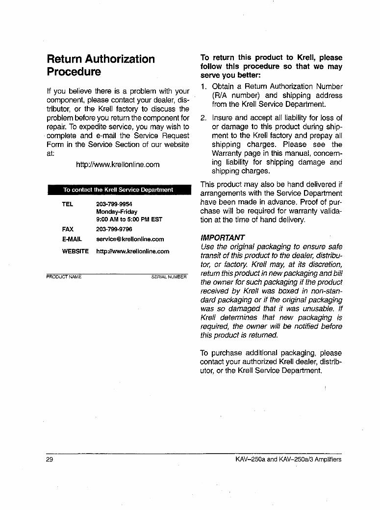
Return AuthorizationProcedure
If you believe there is a problem with yourcomponent, please contact your dealer, dis-tributor, or the Krell factory to discuss theproblem before you return the component forrepair. To expedite service, you may wish tocomplete and e-mail the Service RequestForm in the Service Section of our websiteat:
http://www.krellonline.com
To contact the Krell Service Department
TEL 203-799-9954Monday-Friday9:00 AM to 5:00 PM EST
FAX 203-799-9796
E-MAIL service@ krellonline.com
WEBSITE http://www.krellonline.com
PRODUCT NAME SERIAL NUMBER
To return this product to Krell, pleasefollow this procedure so that we mayserve you better:1. Obtain a Return Authorization Number
(R/A number) and shipping addressfrom the Krell Service Department.
2. Insure and accept all liability for loss ofor damage to this product during ship-ment to the Krell factory and prepay allshipping charges. Please see theWarranty page in this manual, concern-ing liability for shipping damage andshipping charges.
This product may also be hand delivered ifarrangements with the Service Departmenthave been made in advance. Proof of pur-chase will be required for warranty valida-tion at the time of hand delivery.
IMPORTANTUse the original packaging to ensure safetransit of this product to the dealer, distribu-tor, or factory. Krell may, at its discretion,return this product in new packaging and billthe owner for such packaging if the productreceived by Krell was boxed in non-stan-dard packaging or if the original packagingwas so damaged that it was unusable. IfKrell determines that new packaging isrequired, the owner will be notified beforethis product is returned.
To purchase additional packaging, pleasecontact your authorized Krell dealer, distrib-utor, or the Krell Service Department.
29 KAV-250a and KAV-250a/3 Amplifiers
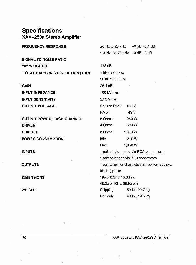
SpecificationsKAV-250a Stereo Amplifier
FREQUENCY RESPONSE
SIGNAL TO NOISE RATIO
"A" WEIGHTED
TOTAL HARMONIC DISTORTION (THD)
GAIN
INPUT IMPEDANCE
INPUT SENSITIVITY
OUTPUT VOLTAGE
OUTPUT POWER, EACH CHANNEL
DRIVEN
BRIDGED
POWER CONSUMPTION
INPUTS
OUTPUTS
DIMENSIONS
WEIGHT
20 Hz to 20 kHz +0 dB, -0.1 dB
0.4 Hz to 170 kHz +0 dB, -3 dB
118dB
1 kHz < 0.06%
20 kHz < 0.25%
26.4 dB
100 kOhms
2.15 Vrms
Peak to Peak
RMS
8 Ohms
4 Ohms
8 Ohms
Idle
Max.
138 V
49 V
250 W
500 W
1,000 W
210W
1,850 W
1 pair single-ended via RCA connectors
1 pair balanced via XLR connectors
1 pair amplifier channels via five-way speaker
binding posts
19w x 6.3h x 15.3d in.
48.3w x 16h x 38.9d cm
Shipping 50 lb., 22.7 kg
Unit only 43 lb., 19.5 kg
30 KAV-250a and KAV-250a/3 Amplifiers
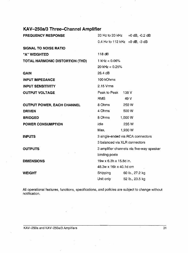
KAV-250a/3 Three-Channel AmplifierFREQUENCY RESPONSE 20 Hz to 20 kHz
0.4 Hz to 112 kHz
SIGNAL TO NOISE RATIO
"A" WEIGHTED
TOTAL HARMONIC DISTORTION (THD)
GAIN
INPUT IMPEDANCE
INPUT SENSITIVITY
OUTPUT VOLTAGE
OUTPUT POWER, EACH CHANNEL
DRIVEN
BRIDGED
POWER CONSUMPTION
INPUTS
OUTPUTS
DIMENSIONS
WEIGHT
+0 dB, -0.2 dB
+0 dB, -3 dB
118dB
1 kHz < 0.06%
20 kHz < 0.25%
26.4 dB
100 kOhms
2.15 Vrms
Peak to Peak
RMS
8 Ohms
4 Ohms
8 Ohms
Idle
Max.
138 V
49 V
250 W
500 W
1,000 W
235 W
1,930 W
3 single-ended via RCA connectors
3 balanced via XLR connectors
3 amplifier channels via five-way speaker
binding posts
19w x 6.3h x 15.8d in.
48.3w x 16h x 40.1d cm
Shipping 60 lb., 27.2 kg
Unit only 52 lb., 23.5 kg
All operational features, functions, specifications, and policies are subject to change withoutnotification.
KAV-250a and KAV-250a/3 Amplifiers 31

Krell Industries, Inc.45 Connair RoadOrange, CT 06477-3650 USA
TEL 203-799-9954FAX 203-799-9796E-MAIL krell@ krellonline.comWEBSITE http://www.krellon line.corn
KAV-250aStereo Power Amplifier
KAV-250a/3Three-Channel Power Amplifier


![Report Jan10 ENG [Kav LaOved -- Economy of the Occupation]](https://img.pdfslide.us/doc/110x75/577d37e01a28ab3a6b96969b/report-jan10-eng-kav-laoved-economy-of-the-occupation.jpg)