Embed Size (px)
Citation preview
LIFT CORPORATION Sht. 1 of 21 DSG# M-14-27 Rev. B Date: 05/31/2017
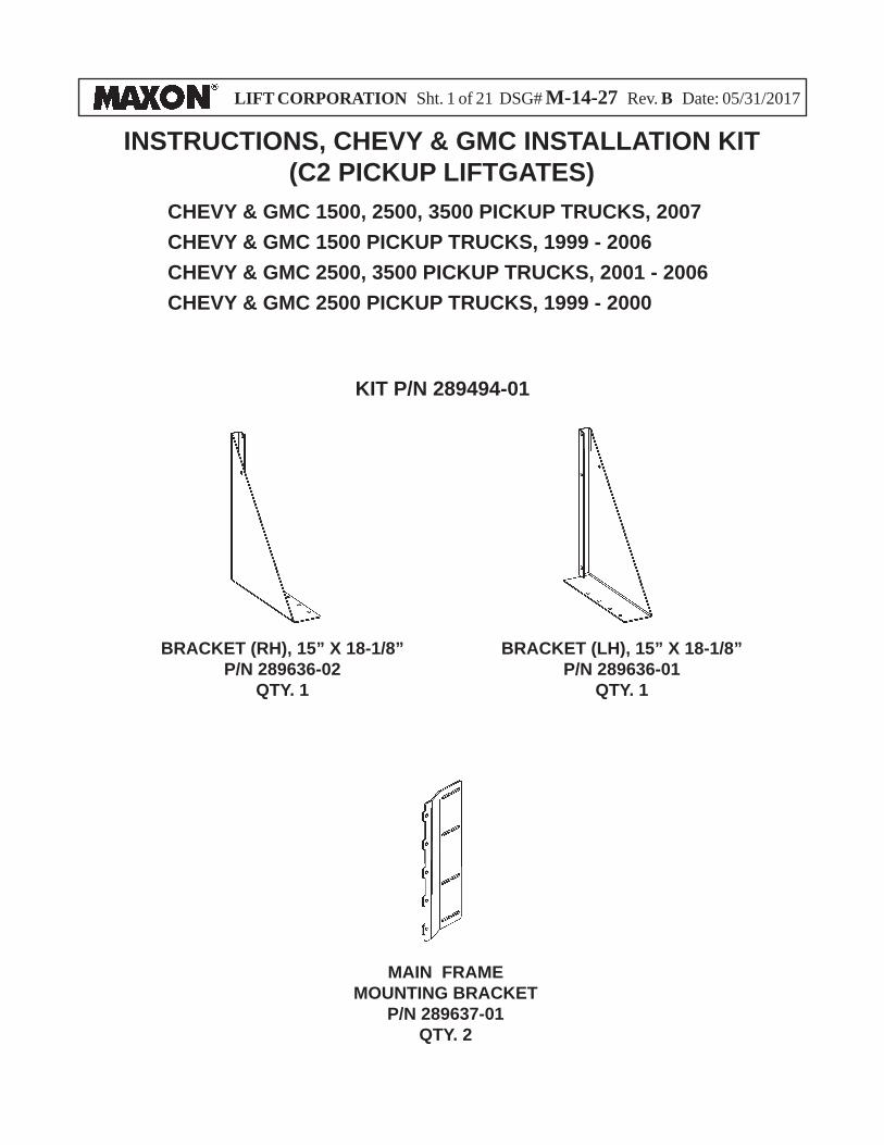
INSTRUCTIONS, CHEVY & GMC INSTALLATION KIT(C2 PICKUP LIFTGATES)
KIT P/N 289494-01
MAIN FRAME MOUNTING BRACKET
P/N 289637-01QTY. 2
BRACKET (RH), 15” X 18-1/8”P/N 289636-02
QTY. 1
CHEVY & GMC 1500, 2500, 3500 PICKUP TRUCKS, 2007 CHEVY & GMC 1500 PICKUP TRUCKS, 1999 - 2006CHEVY & GMC 2500, 3500 PICKUP TRUCKS, 2001 - 2006CHEVY & GMC 2500 PICKUP TRUCKS, 1999 - 2000
BRACKET (LH), 15” X 18-1/8”P/N 289636-01
QTY. 1
LIFT CORPORATION Sht. 2 of 21 DSG# M-14-27 Rev. B Date: 05/31/2017
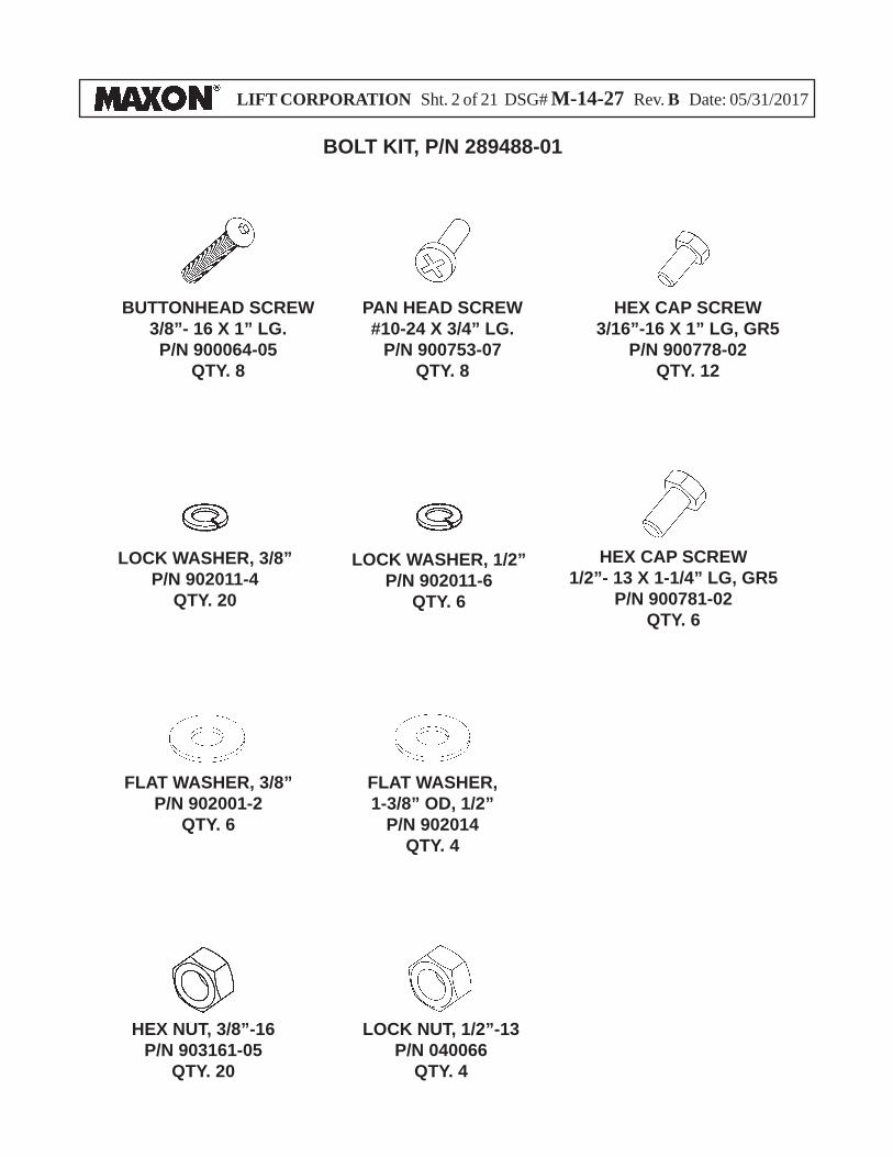
LOCK WASHER, 3/8”P/N 902011-4
QTY. 20
FLAT WASHER, 3/8”P/N 902001-2
QTY. 6
FLAT WASHER, 1-3/8” OD, 1/2”
P/N 902014QTY. 4
HEX CAP SCREW1/2”- 13 X 1-1/4” LG, GR5
P/N 900781-02QTY. 6
BOLT KIT, P/N 289488-01
LOCK WASHER, 1/2”P/N 902011-6
QTY. 6
PAN HEAD SCREW#10-24 X 3/4” LG.
P/N 900753-07QTY. 8
HEX NUT, 3/8”-16P/N 903161-05
QTY. 20
BUTTONHEAD SCREW3/8”- 16 X 1” LG.P/N 900064-05
QTY. 8
HEX CAP SCREW3/16”-16 X 1” LG, GR5
P/N 900778-02QTY. 12
LOCK NUT, 1/2”-13P/N 040066
QTY. 4
LIFT CORPORATION Sht. 3 of 21 DSG# M-14-27 Rev. B Date: 05/31/2017
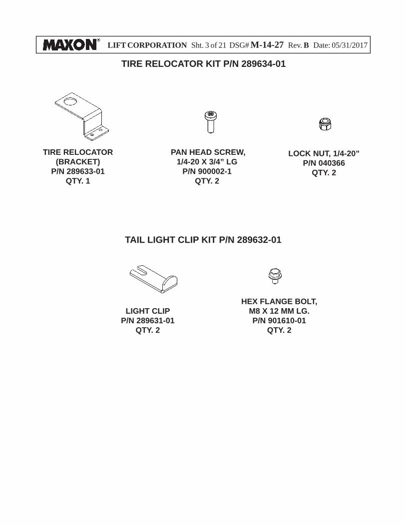
TIRE RELOCATOR KIT P/N 289634-01
TAIL LIGHT CLIP KIT P/N 289632-01
LIGHT CLIPP/N 289631-01
QTY. 2
HEX FLANGE BOLT, M8 X 12 MM LG.P/N 901610-01
QTY. 2
TIRE RELOCATOR (BRACKET)
P/N 289633-01QTY. 1
LOCK NUT, 1/4-20” P/N 040366
QTY. 2
PAN HEAD SCREW, 1/4-20 X 3/4” LG
P/N 900002-1QTY. 2
LIFT CORPORATION Sht. 4 of 21 DSG# M-14-27 Rev. B Date: 05/31/2017
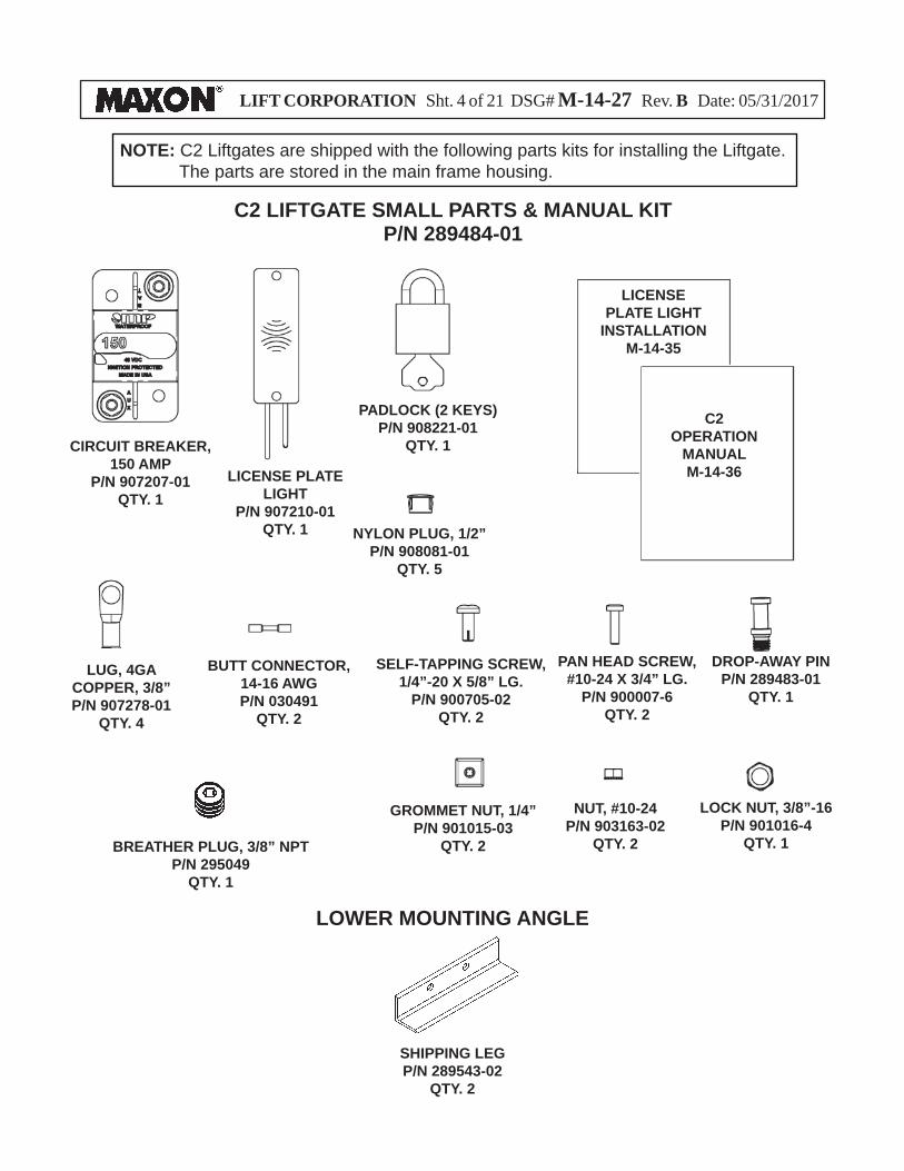
C2 LIFTGATE SMALL PARTS & MANUAL KITP/N 289484-01
NOTE: C2 Liftgates are shipped with the following parts kits for installing the Liftgate. The parts are stored in the main frame housing.
PADLOCK (2 KEYS)P/N 908221-01
QTY. 1
LUG, 4GA COPPER, 3/8”P/N 907278-01
QTY. 4
LICENSE PLATE LIGHT
P/N 907210-01QTY. 1
BUTT CONNECTOR, 14-16 AWGP/N 030491
QTY. 2
CIRCUIT BREAKER, 150 AMP
P/N 907207-01QTY. 1
SELF-TAPPING SCREW, 1/4”-20 X 5/8” LG.
P/N 900705-02QTY. 2
GROMMET NUT, 1/4”P/N 901015-03
QTY. 2
LOWER MOUNTING ANGLE
SHIPPING LEGP/N 289543-02
QTY. 2
NYLON PLUG, 1/2”P/N 908081-01
QTY. 5
PAN HEAD SCREW, #10-24 X 3/4” LG.
P/N 900007-6QTY. 2
NUT, #10-24P/N 903163-02
QTY. 2
DROP-AWAY PINP/N 289483-01
QTY. 1
LOCK NUT, 3/8”-16P/N 901016-4
QTY. 1
C2 OPERATION
MANUALM-14-36
LICENSE PLATE LIGHT
INSTALLATIONM-14-35
BREATHER PLUG, 3/8” NPTP/N 295049
QTY. 1
LIFT CORPORATION Sht. 5 of 21 DSG# M-14-27 Rev. B Date: 05/31/2017
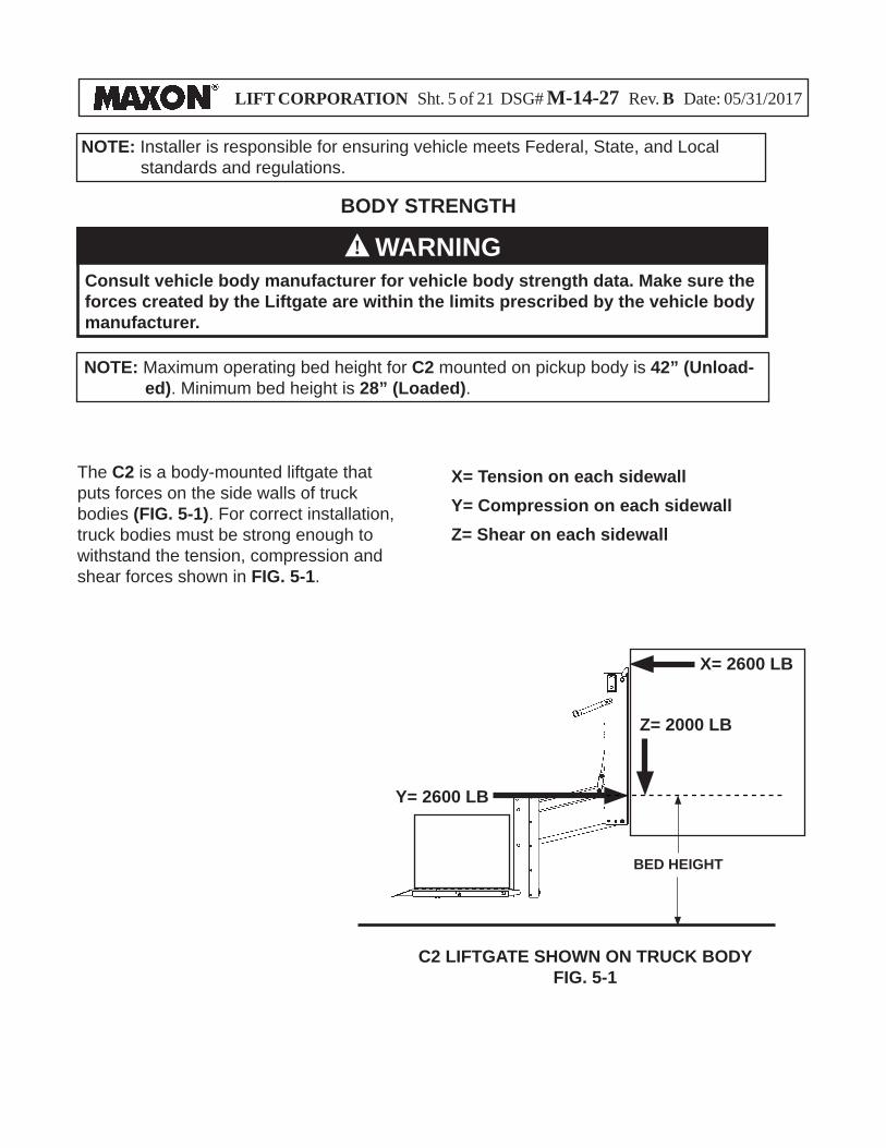
The C2 is a body-mounted liftgate that puts forces on the side walls of truck bodies (FIG. 5-1). For correct installation, truck bodies must be strong enough to withstand the tension, compression and shear forces shown in FIG. 5-1.
X= Tension on each sidewallY= Compression on each sidewallZ= Shear on each sidewall
Consult vehicle body manufacturer for vehicle body strength data. Make sure the forces created by the Liftgate are within the limits prescribed by the vehicle body manufacturer.
WARNINGBODY STRENGTH
NOTE: Maximum operating bed height for C2 mounted on pickup body is 42” (Unload-ed). Minimum bed height is 28” (Loaded).
!
NOTE: Installer is responsible for ensuring vehicle meets Federal, State, and Local standards and regulations.
C2 LIFTGATE SHOWN ON TRUCK BODYFIG. 5-1
X= 2600 LB
BED HEIGHT
Z= 2000 LB
Y= 2600 LB
LIFT CORPORATION Sht. 6 of 21 DSG# M-14-27 Rev. B Date: 05/31/2017
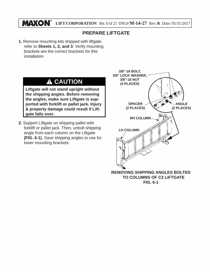
PREPARE LIFTGATE1. Remove mounting kits shipped with liftgate.
refer to Sheets 1, 2, and 3. Verify mounting brackets are the correct brackets for this installation.
LH COLUMN
RH COLUMN
REMOVING SHIPPING ANGLES BOLTED TO COLUMNS OF C2 LIFTGATE
FIG. 6-1
ANGLE(2 PLACES)
3/8”-16 BOLT, 3/8” LOCK WASHER,
3/8”-16 NUT(4 PLACES)
2. Support Liftgate on shipping pallet with forklift or pallet jack. Then, unbolt shipping angle from each column on the Liftgate (FIG. 6-1). Save shipping angles to use for lower mounting brackets.
`
Liftgate will not stand upright without the shipping angles. Before removing the angles, make sure Liftgate is sup-ported with forklift or pallet jack. Injury & property damage could result if Lift-gate falls over.
CAUTION!
SPACER(2 PLACES)
LIFT CORPORATION Sht. 7 of 21 DSG# M-14-27 Rev. B Date: 05/31/2017
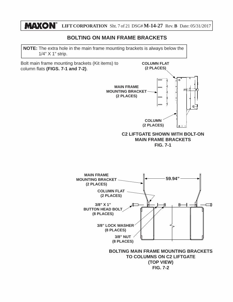
BOLTING ON MAIN FRAME BRACKETS
NOTE: The extra hole in the main frame mounting brackets is always below the 1/4” X 1” strip.
Bolt main frame mounting brackets (Kit items) to column fl ats (FIGS. 7-1 and 7-2).
C2 LIFTGATE SHOWN WITH BOLT-ON MAIN FRAME BRACKETS
FIG. 7-1
MAIN FRAMEMOUNTING BRACKET
(2 PLACES)
COLUMN(2 PLACES)
COLUMN FLAT(2 PLACES)
59.94”
3/8” LOCK WASHER(8 PLACES)
3/8” NUT(8 PLACES)
3/8” X 1”BUTTON HEAD BOLT
(8 PLACES)
MAIN FRAMEMOUNTING BRACKET
(2 PLACES)
BOLTING MAIN FRAME MOUNTING BRACKETS TO COLUMNS ON C2 LIFTGATE
(TOP VIEW)FIG. 7-2
COLUMN FLAT(2 PLACES)
LIFT CORPORATION Sht. 8 of 21 DSG# M-14-27 Rev. B Date: 05/31/2017
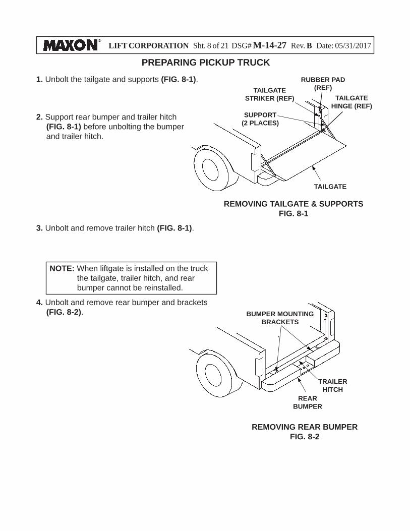
PREPARING PICKUP TRUCK
2. Support rear bumper and trailer hitch (FIG. 8-1) before unbolting the bumper and trailer hitch.
3. Unbolt and remove trailer hitch (FIG. 8-1).
4. Unbolt and remove rear bumper and brackets (FIG. 8-2).
1. Unbolt the tailgate and supports (FIG. 8-1).
NOTE: When liftgate is installed on the truck the tailgate, trailer hitch, and rear bumper cannot be reinstalled.
TAILGATE STRIKER (REF) TAILGATE
HINGE (REF)
REAR BUMPER
TAILGATE
REMOVING TAILGATE & SUPPORTSFIG. 8-1
REMOVING REAR BUMPERFIG. 8-2
BUMPER MOUNTINGBRACKETS
TRAILERHITCH
RUBBER PAD (REF)
SUPPORT(2 PLACES)
LIFT CORPORATION Sht. 9 of 21 DSG# M-14-27 Rev. B Date: 05/31/2017
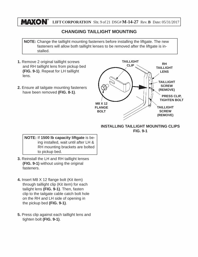
CHANGING TAILLIGHT MOUNTING
1. Remove 2 original taillight screws and RH taillight lens from pickup bed (FIG. 9-1). Repeat for LH taillight lens.
INSTALLING TAILLIGHT MOUNTING CLIPSFIG. 9-1
RH TAILLIGHT
LENS
NOTE: Change the taillight mounting fasteners before installing the liftgate. The new fasteners will allow both taillight lenses to be removed after the liftgate is in-stalled.
2. Ensure all tailgate mounting fasteners have been removed (FIG. 8-1).
3. Reinstall the LH and RH taillight lenses (FIG. 9-1) without using the original fasteners.
4. Insert M8 X 12 fl ange bolt (Kit item) through taillight clip (Kit item) for each tailight lens (FIG. 9-1). Then, fasten clip to the tailgate cable catch bolt hole on the RH and LH side of opening in the pickup bed (FIG. 9-1).
5. Press clip against each taillight lens and tighten bolt (FIG. 9-1).
TAILLIGHTCLIP
M8 X 12FLANGE
BOLT
TAILLIGHTSCREW
(REMOVE)
TAILLIGHTSCREW
(REMOVE)
PRESS CLIP, TIGHTEN BOLT
NOTE: If 1500 lb capacity liftgate is be-ing installed, wait until after LH & RH mounting brackets are bolted to pickup bed.
LIFT CORPORATION Sht. 10 of 21 DSG# M-14-27 Rev. B Date: 05/31/2017
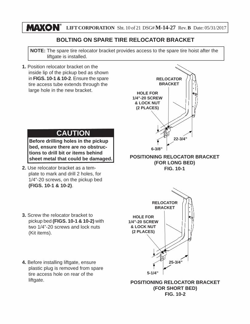
BOLTING ON SPARE TIRE RELOCATOR BRACKET
NOTE: The spare tire relocator bracket provides access to the spare tire hoist after the liftgate is installed.
1. Position relocator bracket on the inside lip of the pickup bed as shown in FIGS. 10-1 & 10-2. Ensure the spare tire access tube extends through the large hole in the new bracket.
POSITIONING RELOCATOR BRACKET(FOR LONG BED)
FIG. 10-1
25-3/4”
6-3/8”
POSITIONING RELOCATOR BRACKET(FOR SHORT BED)
FIG. 10-2
5-1/4”
RELOCATOR BRACKET
RELOCATOR BRACKET
HOLE FOR 1/4”-20 SCREW
& LOCK NUT(2 PLACES)
2. Use relocator bracket as a tem-plate to mark and drill 2 holes, for 1/4”-20 screws, on the pickup bed (FIGS. 10-1 & 10-2).
HOLE FOR 1/4”-20 SCREW
& LOCK NUT(2 PLACES)
CAUTIONBefore drilling holes in the pickup bed, ensure there are no obstruc-tions to drill bit or items behind sheet metal that could be damaged.
3. Screw the relocator bracket to pickup bed (FIGS. 10-1 & 10-2) with two 1/4”-20 screws and lock nuts (Kit items).
4. Before installing liftgate, ensure plastic plug is removed from spare tire access hole on rear of the liftgate.
22-3/4”
LIFT CORPORATION Sht. 11 of 21 DSG# M-14-27 Rev. B Date: 05/31/2017
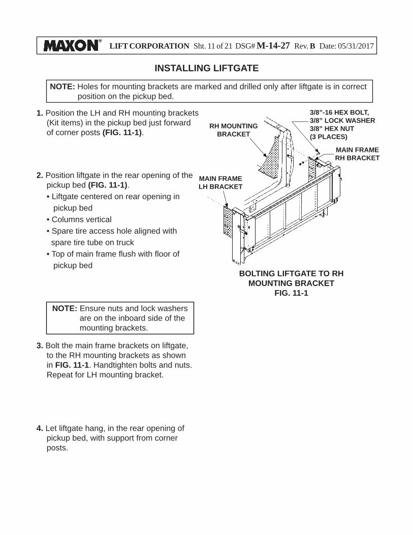
INSTALLING LIFTGATE
1. Position the LH and RH mounting brackets (Kit items) in the pickup bed just forward of corner posts (FIG. 11-1).
NOTE: Holes for mounting brackets are marked and drilled only after liftgate is in correct position on the pickup bed.
2. Position liftgate in the rear opening of the pickup bed (FIG. 11-1).
• Liftgate centered on rear opening in pickup bed
• Columns vertical • Spare tire access hole aligned with spare tire tube on truck • Top of main frame fl ush with fl oor of pickup bed
3. Bolt the main frame brackets on liftgate, to the RH mounting brackets as shown in FIG. 11-1. Handtighten bolts and nuts. Repeat for LH mounting bracket.
MAIN FRAMERH BRACKET
RH MOUNTING BRACKET
MAIN FRAMELH BRACKET
3/8”-16 HEX BOLT,3/8” LOCK WASHER3/8” HEX NUT(3 PLACES)
BOLTING LIFTGATE TO RH MOUNTING BRACKET
FIG. 11-1
NOTE: Ensure nuts and lock washers are on the inboard side of the mounting brackets.
4. Let liftgate hang, in the rear opening of pickup bed, with support from corner posts.
LIFT CORPORATION Sht. 12 of 21 DSG# M-14-27 Rev. B Date: 05/31/2017
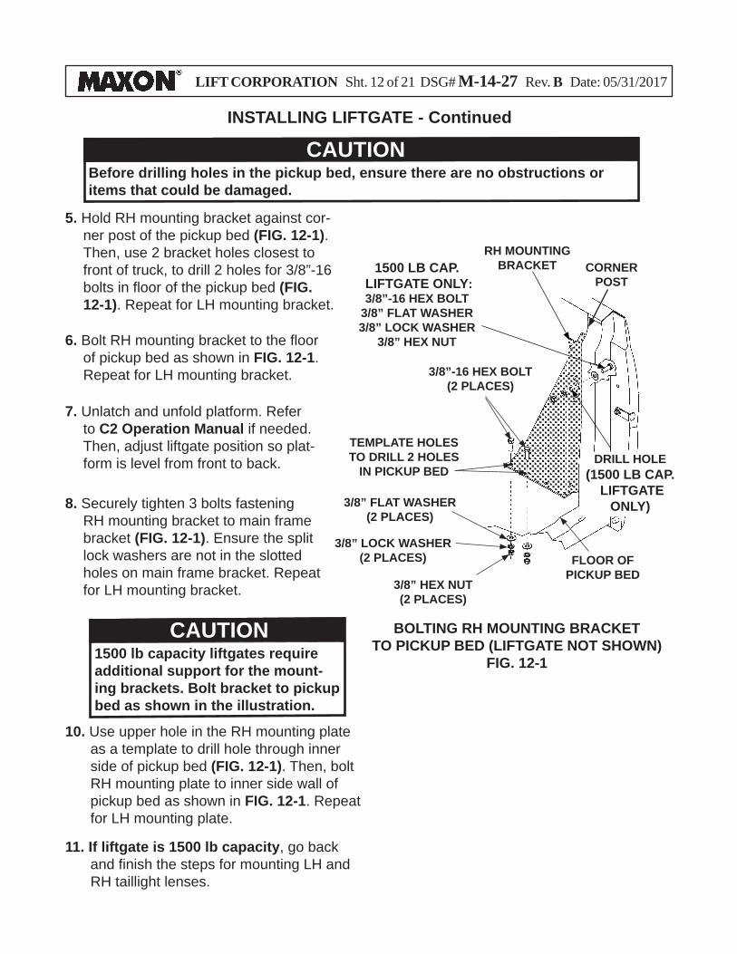
BOLTING RH MOUNTING BRACKET TO PICKUP BED (LIFTGATE NOT SHOWN)
FIG. 12-1
3/8” FLAT WASHER (2 PLACES)
RH MOUNTING BRACKET
FLOOR OF PICKUP BED
CAUTIONBefore drilling holes in the pickup bed, ensure there are no obstructions or items that could be damaged.
5. Hold RH mounting bracket against cor-ner post of the pickup bed (FIG. 12-1). Then, use 2 bracket holes closest to front of truck, to drill 2 holes for 3/8”-16 bolts in fl oor of the pickup bed (FIG. 12-1). Repeat for LH mounting bracket.
CORNERPOST
TEMPLATE HOLES TO DRILL 2 HOLES
IN PICKUP BED
6. Bolt RH mounting bracket to the fl oor of pickup bed as shown in FIG. 12-1. Repeat for LH mounting bracket.
7. Unlatch and unfold platform. Refer to C2 Operation Manual if needed. Then, adjust liftgate position so plat-form is level from front to back.
8. Securely tighten 3 bolts fastening RH mounting bracket to main frame bracket (FIG. 12-1). Ensure the split lock washers are not in the slotted holes on main frame bracket. Repeat for LH mounting bracket.
10. Use upper hole in the RH mounting plate as a template to drill hole through inner side of pickup bed (FIG. 12-1). Then, bolt RH mounting plate to inner side wall of pickup bed as shown in FIG. 12-1. Repeat for LH mounting plate.
DRILL HOLE (1500 LB CAP.
LIFTGATE ONLY)
INSTALLING LIFTGATE - Continued
3/8”-16 HEX BOLT(2 PLACES)
3/8” LOCK WASHER(2 PLACES)
3/8” HEX NUT(2 PLACES)
1500 LB CAP. LIFTGATE ONLY: 3/8”-16 HEX BOLT
3/8” FLAT WASHER3/8” LOCK WASHER
3/8” HEX NUT
CAUTION1500 lb capacity liftgates require additional support for the mount-ing brackets. Bolt bracket to pickup bed as shown in the illustration.
11. If liftgate is 1500 lb capacity, go back and fi nish the steps for mounting LH and RH taillight lenses.
LIFT CORPORATION Sht. 13 of 21 DSG# M-14-27 Rev. B Date: 05/31/2017
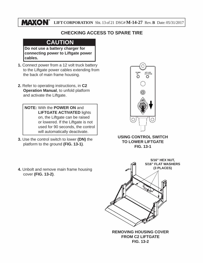
CHECKING ACCESS TO SPARE TIRE
1. Connect power from a 12 volt truck battery to the Liftgate power cables extending from the back of main frame housing.
3. Use the control switch to lower (DN) the platform to the ground (FIG. 13-1).
USING CONTROL SWITCHTO LOWER LIFTGATE
FIG. 13-1
CAUTIONDo not use a battery charger for connecting power to Liftgate power cables.
2. Refer to operating instructions, in C2 Operation Manual, to unfold platform and activate the Liftgate.
NOTE: With the POWER ON and LIFTGATE ACTIVATED lights on, the Liftgate can be raised or lowered. If the Liftgate is not used for 90 seconds, the control will automatically deactivate.
4. Unbolt and remove main frame housing cover (FIG. 13-2).
REMOVING HOUSING COVER FROM C2 LIFTGATE
FIG. 13-2
5/16” HEX NUT, 5/16” FLAT WASHERS
(3 PLACES)
LIFT CORPORATION Sht. 14 of 21 DSG# M-14-27 Rev. B Date: 05/31/2017
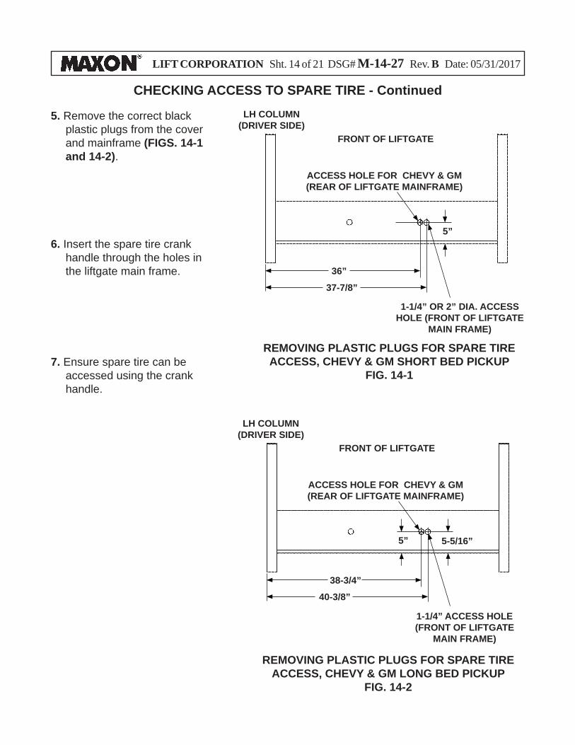
37-7/8”
FRONT OF LIFTGATE
LH COLUMN(DRIVER SIDE)
ACCESS HOLE FOR CHEVY & GM(REAR OF LIFTGATE MAINFRAME)
5. Remove the correct black plastic plugs from the cover and mainframe (FIGS. 14-1 and 14-2).
6. Insert the spare tire crank handle through the holes in the liftgate main frame.
7. Ensure spare tire can be accessed using the crank handle.
REMOVING PLASTIC PLUGS FOR SPARE TIRE ACCESS, CHEVY & GM SHORT BED PICKUP
FIG. 14-1
36”
5”
40-3/8”
5-5/16”
FRONT OF LIFTGATE
LH COLUMN(DRIVER SIDE)
ACCESS HOLE FOR CHEVY & GM(REAR OF LIFTGATE MAINFRAME)
38-3/4”
5”
1-1/4” OR 2” DIA. ACCESS HOLE (FRONT OF LIFTGATE
MAIN FRAME)
REMOVING PLASTIC PLUGS FOR SPARE TIRE ACCESS, CHEVY & GM LONG BED PICKUP
FIG. 14-2
1-1/4” ACCESS HOLE (FRONT OF LIFTGATE
MAIN FRAME)
CHECKING ACCESS TO SPARE TIRE - Continued
LIFT CORPORATION Sht. 15 of 21 DSG# M-14-27 Rev. B Date: 05/31/2017
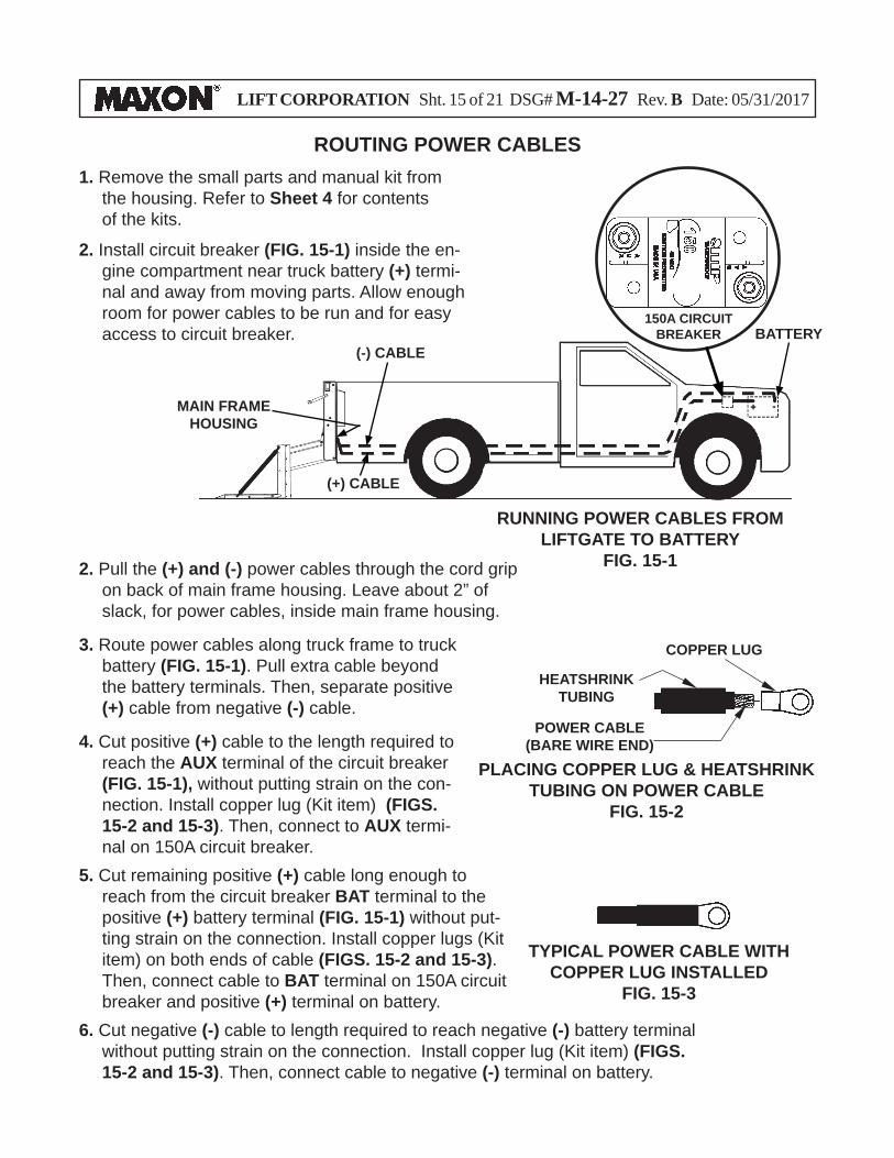
ROUTING POWER CABLES1. Remove the small parts and manual kit from
the housing. Refer to Sheet 4 for contents of the kits.
2. Install circuit breaker (FIG. 15-1) inside the en-gine compartment near truck battery (+) termi-nal and away from moving parts. Allow enough room for power cables to be run and for easy access to circuit breaker.
2. Pull the (+) and (-) power cables through the cord grip on back of main frame housing. Leave about 2” of slack, for power cables, inside main frame housing.
3. Route power cables along truck frame to truck battery (FIG. 15-1). Pull extra cable beyond the battery terminals. Then, separate positive (+) cable from negative (-) cable.
4. Cut positive (+) cable to the length required to reach the AUX terminal of the circuit breaker (FIG. 15-1), without putting strain on the con-nection. Install copper lug (Kit item) (FIGS. 15-2 and 15-3). Then, connect to AUX termi-nal on 150A circuit breaker.
5. Cut remaining positive (+) cable long enough to reach from the circuit breaker BAT terminal to the positive (+) battery terminal (FIG. 15-1) without put-ting strain on the connection. Install copper lugs (Kit item) on both ends of cable (FIGS. 15-2 and 15-3). Then, connect cable to BAT terminal on 150A circuit breaker and positive (+) terminal on battery.
RUNNING POWER CABLES FROM LIFTGATE TO BATTERY
FIG. 15-1
(+) CABLE
(-) CABLEBATTERY
150A CIRCUIT BREAKER
MAIN FRAME HOUSING
PLACING COPPER LUG & HEATSHRINK TUBING ON POWER CABLE
FIG. 15-2
COPPER LUG
POWER CABLE (BARE WIRE END)
HEATSHRINK TUBING
TYPICAL POWER CABLE WITH COPPER LUG INSTALLED
FIG. 15-3
6. Cut negative (-) cable to length required to reach negative (-) battery terminal without putting strain on the connection. Install copper lug (Kit item) (FIGS. 15-2 and 15-3). Then, connect cable to negative (-) terminal on battery.
LIFT CORPORATION Sht. 16 of 21 DSG# M-14-27 Rev. B Date: 05/31/2017
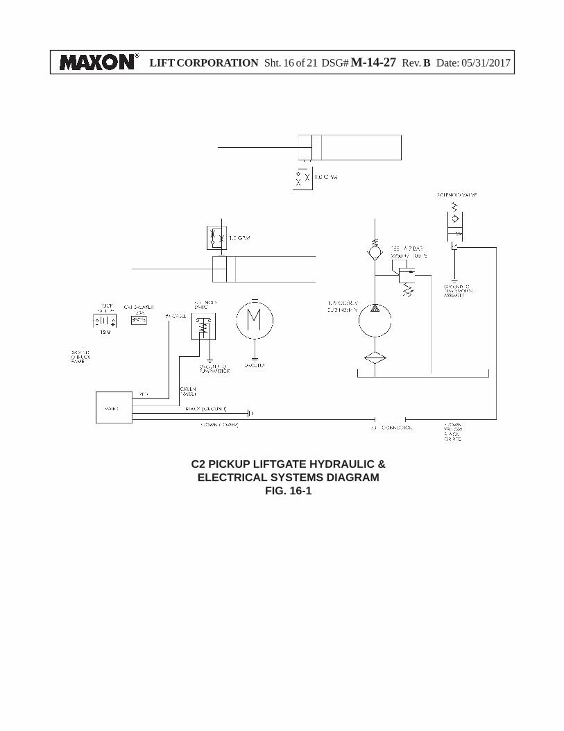
C2 PICKUP LIFTGATE HYDRAULIC & ELECTRICAL SYSTEMS DIAGRAM
FIG. 16-1
LIFT CORPORATION Sht. 17 of 21 DSG# M-14-27 Rev. B Date: 05/31/2017
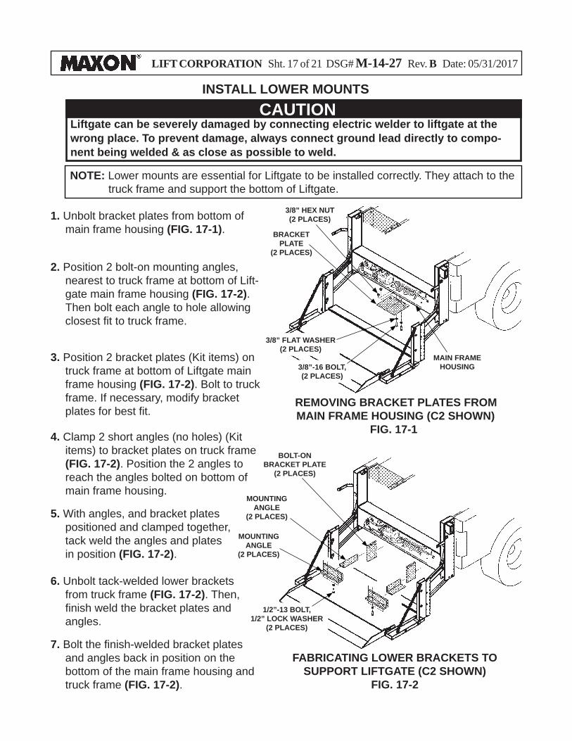
INSTALL LOWER MOUNTS
2. Position 2 bolt-on mounting angles, nearest to truck frame at bottom of Lift-gate main frame housing (FIG. 17-2). Then bolt each angle to hole allowing closest fi t to truck frame.
NOTE: Lower mounts are essential for Liftgate to be installed correctly. They attach to the truck frame and support the bottom of Liftgate.
3. Position 2 bracket plates (Kit items) on truck frame at bottom of Liftgate main frame housing (FIG. 17-2). Bolt to truck frame. If necessary, modify bracket plates for best fi t.
4. Clamp 2 short angles (no holes) (Kit items) to bracket plates on truck frame (FIG. 17-2). Position the 2 angles to reach the angles bolted on bottom of main frame housing.
5. With angles, and bracket plates positioned and clamped together, tack weld the angles and plates in position (FIG. 17-2).
6. Unbolt tack-welded lower brackets from truck frame (FIG. 17-2). Then, fi nish weld the bracket plates and angles.
7. Bolt the fi nish-welded bracket plates and angles back in position on the bottom of the main frame housing and truck frame (FIG. 17-2).
FABRICATING LOWER BRACKETS TOSUPPORT LIFTGATE (C2 SHOWN)
FIG. 17-2
MOUNTING ANGLE
(2 PLACES)
BOLT-ON BRACKET PLATE
(2 PLACES)
REMOVING BRACKET PLATES FROM MAIN FRAME HOUSING (C2 SHOWN)
FIG. 17-1
1. Unbolt bracket plates from bottom of main frame housing (FIG. 17-1).
MAIN FRAME HOUSING
3/8” HEX NUT(2 PLACES)
BRACKET PLATE
(2 PLACES)
3/8”-16 BOLT, (2 PLACES)
1/2”-13 BOLT, 1/2” LOCK WASHER
(2 PLACES)
3/8” FLAT WASHER(2 PLACES)
MOUNTING ANGLE
(2 PLACES)
Liftgate can be severely damaged by connecting electric welder to liftgate at the wrong place. To prevent damage, always connect ground lead directly to compo-nent being welded & as close as possible to weld.
CAUTION
LIFT CORPORATION Sht. 18 of 21 DSG# M-14-27 Rev. B Date: 05/31/2017
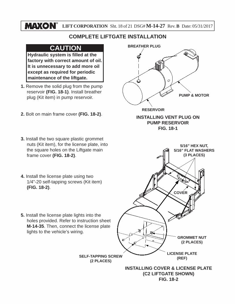
COMPLETE LIFTGATE INSTALLATION
1. Remove the solid plug from the pump reservoir (FIG. 18-1). Install breather plug (Kit item) in pump reservoir.
BREATHER PLUG
PUMP & MOTOR
3. Install the two square plastic grommet nuts (Kit item), for the license plate, into the square holes on the Liftgate main frame cover (FIG. 18-2).
4. Install the license plate using two 1/4”-20 self-tapping screws (Kit item) (FIG. 18-2).
5. Install the license plate lights into the holes provided. Refer to instruction sheet M-14-35. Then, connect the license plate lights to the vehicle’s wiring.
INSTALLING VENT PLUG ON PUMP RESERVOIR
FIG. 18-1
RESERVOIR
INSTALLING COVER & LICENSE PLATE (C2 LIFTGATE SHOWN)
FIG. 18-2
2. Bolt on main frame cover (FIG. 18-2).
5/16” HEX NUT, 5/16” FLAT WASHERS
(3 PLACES)
GROMMET NUT(2 PLACES)
COVER
SELF-TAPPING SCREW (2 PLACES)
LICENSE PLATE(REF)
Hydraulic system is fi lled at the factory with correct amount of oil. It is unnecessary to add more oil except as required for periodic maintenance of the liftgate.
CAUTION
LIFT CORPORATION Sht. 19 of 21 DSG# M-14-27 Rev. B Date: 05/31/2017
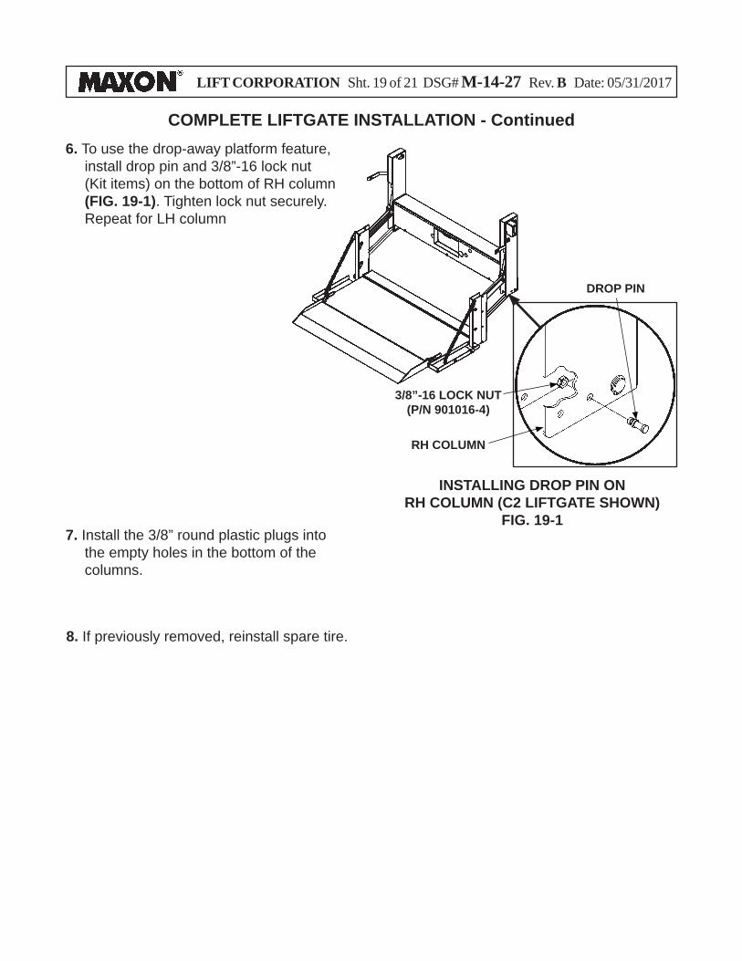
COMPLETE LIFTGATE INSTALLATION - Continued
8. If previously removed, reinstall spare tire.
INSTALLING DROP PIN ONRH COLUMN (C2 LIFTGATE SHOWN)
FIG. 19-1
DROP PIN
6. To use the drop-away platform feature, install drop pin and 3/8”-16 lock nut (Kit items) on the bottom of RH column (FIG. 19-1). Tighten lock nut securely. Repeat for LH column
3/8”-16 LOCK NUT(P/N 901016-4)
RH COLUMN
7. Install the 3/8” round plastic plugs into the empty holes in the bottom of the columns.
LIFT CORPORATION Sht. 20 of 21 DSG# M-14-27 Rev. B Date: 05/31/2017
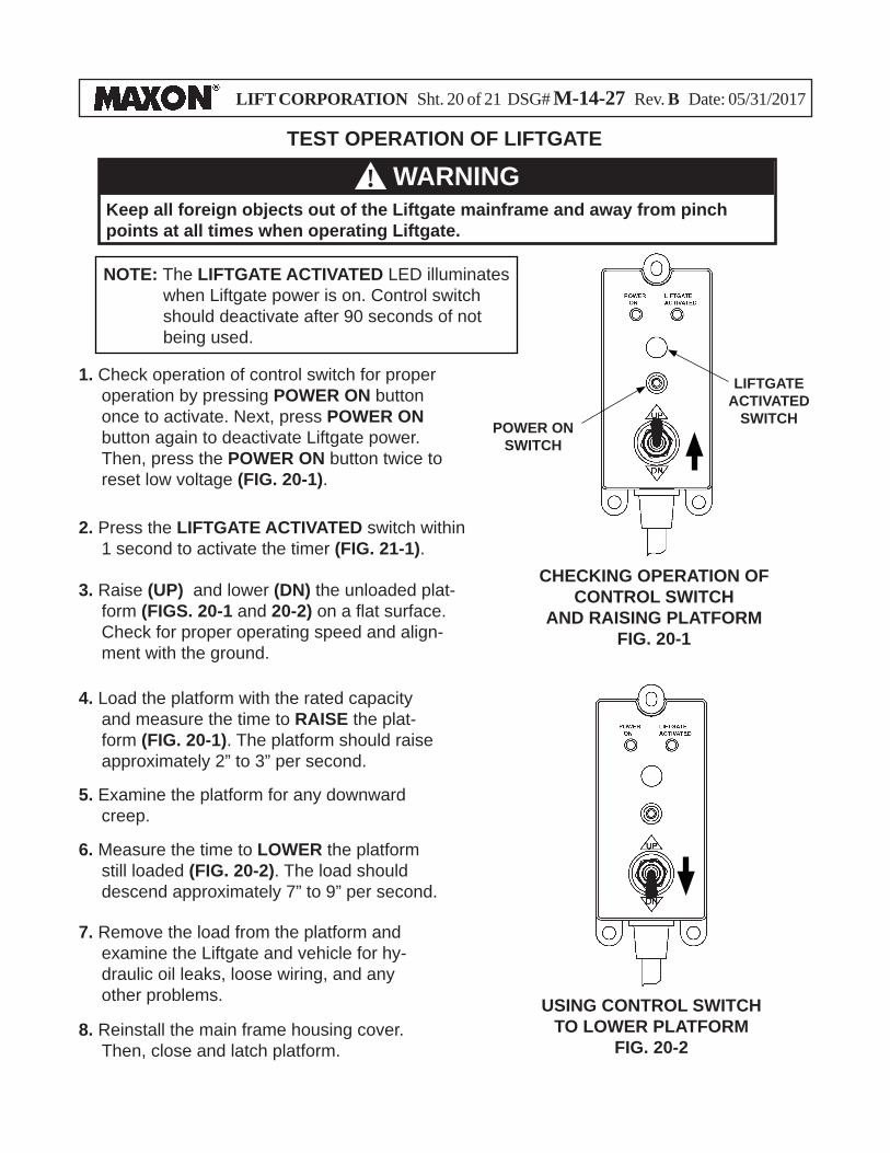
1. Check operation of control switch for proper operation by pressing POWER ON button once to activate. Next, press POWER ON button again to deactivate Liftgate power. Then, press the POWER ON button twice to reset low voltage (FIG. 20-1).
Keep all foreign objects out of the Liftgate mainframe and away from pinch points at all times when operating Liftgate.
WARNING!TEST OPERATION OF LIFTGATE
NOTE: The LIFTGATE ACTIVATED LED illuminates when Liftgate power is on. Control switch should deactivate after 90 seconds of not being used.
POWER ON SWITCH
CHECKING OPERATION OFCONTROL SWITCH
AND RAISING PLATFORMFIG. 20-1
3. Raise (UP) and lower (DN) the unloaded plat-form (FIGS. 20-1 and 20-2) on a fl at surface. Check for proper operating speed and align-ment with the ground.
USING CONTROL SWITCHTO LOWER PLATFORM
FIG. 20-2
4. Load the platform with the rated capacity and measure the time to RAISE the plat-form (FIG. 20-1). The platform should raise approximately 2” to 3” per second.
5. Examine the platform for any downward creep.
6. Measure the time to LOWER the platform still loaded (FIG. 20-2). The load should descend approximately 7” to 9” per second.
7. Remove the load from the platform and examine the Liftgate and vehicle for hy-draulic oil leaks, loose wiring, and any other problems.
8. Reinstall the main frame housing cover. Then, close and latch platform.
LIFTGATE ACTIVATED
SWITCH
2. Press the LIFTGATE ACTIVATED switch within 1 second to activate the timer (FIG. 21-1).
LIFT CORPORATION Sht. 21 of 21 DSG# M-14-27 Rev. B Date: 05/31/2017
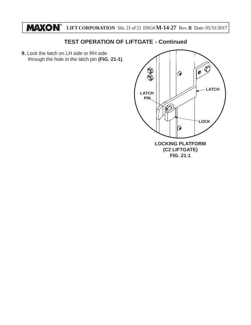
9. Lock the latch on LH side or RH side through the hole in the latch pin (FIG. 21-1).
TEST OPERATION OF LIFTGATE - Continued
LATCHPIN
LATCH
LOCKING PLATFORM(C2 LIFTGATE)
FIG. 21-1
LOCK