Embed Size (px)
Citation preview
pg. 1 655520
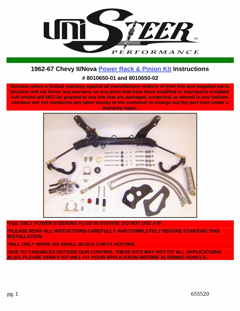
1962-67 Chevy II/Nova Power Rack & Pinion Kit Instructions
# 8010650-01 and 8010650-02
Unisteer offers a limited warranty against all manufacturer defects of their kits and supplied parts. Unisteer will not honor any warranty on any parts that have been modified or improperly installed. Full refund will NOT be granted to any kits that are damaged, scratched, or altered in any fashion. Unisteer will not reimburse any labor money to the customer to change out the part even under a
warranty repair.
*USE ONLY POWER STEERING FLUID IN SYSTEM. DO NOT USE ATF.
*PLEASE READ ALL INSTUCTIONS CAREFULLY AND COMPLETELY BEFORE STARTING THISINSTALLATION.
*WILL ONLY WORK ON SMALL BLOCK CHEVY MOTORS.
*DUE TO VARIABLES OUTSIDE OUR CONTROL THESE KITS MAY NOT FIT ALL APPLICATIONS.ALSO, PLEASE VERIFY KIT WILL FIT YOUR APPLICATION BEFORE ALTERING VEHICLE.
pg. 2 655520
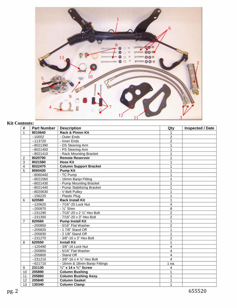
Kit Contents: # Part Number Description Qty Inspected / Date 1 8010640 Rack & Pinion Kit 1
--10002 - Outer Ends 2
--113720 - Inner Ends 2
--8021390 - DS Steering Arm 1
--8021400 - PS Steering Arm 1
--8021410 - Rack Mounting Bracket 1
2 8020790 Remote Reservoir 1
3 8021580 Hose Kit 1
4 8022470 Column Support Bracket 1
5 8060430 Pump Kit 1
--8060440 - TC Pump 1
--8021560 - 16mm Banjo Fitting 1
--8021430 - Pump Mounting Bracket 1
--8021440 - Pump Stabilizing Bracket 1
--8020630 - V-Belt Pulley 1
--156220 - Plastic Plug 1
6 620580 Rack Install Kit 1
--120620 - 7/16”-20 Lock Nut 4
--200970 - ¼” Shim 8
--231290 - 7/16”-20 x 2 ½” Hex Bolt 2
--231300 - 7/16”-20 x 3” Hex Bolt 2
7 620560 Pump Install Kit 1
--200850 - 5/16” Flat Washer 2
--205820 - 1 7/8” Stand Off 1
--205830 - 2 1/8” Stand Off 1
--231270 - 3/8”-16 x 3” Hex Bolt 2
8 620550 Install Kit 1
--120490 - 3/8”-16 Lock Nut 4
--200850 - 5/16” Flat Washer 4
--205800 - Stand Off 4
--231210 - 3/8”-16 x 4 ½” Hex Bolt 4
--621710 - 16mm & 18mm Banjo Fittings 1 ea.
9 231130 ¼” x 14 x ¾” Screw 4
10 205890 Column Bushing 1
11 205860 Column Bushing Assy. 1
12 205840 Column Gasket 1
13 130340 Column Clamp 1
2
7
6
9
3
1
7
13
10
1112
4
5
8
9
pg. 3 655520
This kit is designed for 1962-1967 Chevy II’s and Novas, but the following provisions apply:
BEFORE STARTING YOUR CAR MUST MEET THESE PROVISIONS:
- Small Block Chevy Motor Only. - Equipped with Hedman Chevy II Headers or Custom Headers - Stock Front Suspension - Stock Spindles or aftermarket spindles with detachable steering arms - Floor shift transmission - Rear Sump Oil Pan & Pickup
Furthermore, when installing this Rack & Pinion kit, you will need to acquire a new steering shaft. Unisteer can supply a shaft kit; due to variation in the column there are three kits available. If you wish to do your own shafting, typically 3 U-joints and a support bearing are required, the pinion size on the rack is GM 17mm DD. Also an aftermarket column may be used with this kit or the original column must be modified; instructions on this modification are included.
Disassembly
In order to perform this installation the front end of the car must be off the ground. A lift works best, but jack stands will work.
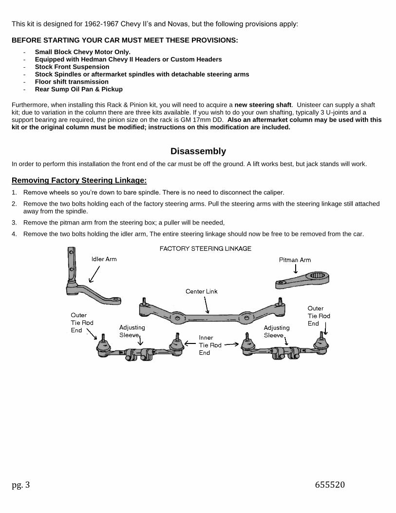
Removing Factory Steering Linkage:
1. Remove wheels so you’re down to bare spindle. There is no need to disconnect the caliper.
2. Remove the two bolts holding each of the factory steering arms. Pull the steering arms with the steering linkage still attachedaway from the spindle.
3. Remove the pitman arm from the steering box; a puller will be needed,
4. Remove the two bolts holding the idler arm, The entire steering linkage should now be free to be removed from the car.
pg. 4 655520
Column and Steering Box Removal:
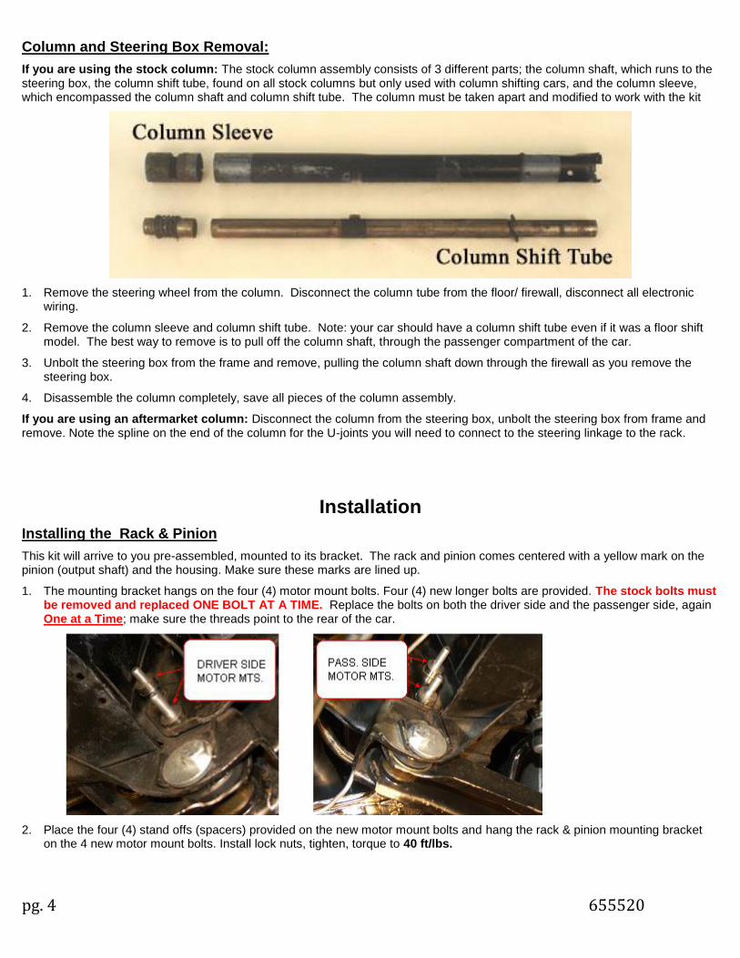
If you are using the stock column: The stock column assembly consists of 3 different parts; the column shaft, which runs to the steering box, the column shift tube, found on all stock columns but only used with column shifting cars, and the column sleeve, which encompassed the column shaft and column shift tube. The column must be taken apart and modified to work with the kit
1. Remove the steering wheel from the column. Disconnect the column tube from the floor/ firewall, disconnect all electronicwiring.
2. Remove the column sleeve and column shift tube. Note: your car should have a column shift tube even if it was a floor shiftmodel. The best way to remove is to pull off the column shaft, through the passenger compartment of the car.
3. Unbolt the steering box from the frame and remove, pulling the column shaft down through the firewall as you remove thesteering box.
4. Disassemble the column completely, save all pieces of the column assembly.
If you are using an aftermarket column: Disconnect the column from the steering box, unbolt the steering box from frame and remove. Note the spline on the end of the column for the U-joints you will need to connect to the steering linkage to the rack.
Installation
Installing the Rack & Pinion
This kit will arrive to you pre-assembled, mounted to its bracket. The rack and pinion comes centered with a yellow mark on the pinion (output shaft) and the housing. Make sure these marks are lined up.
1. The mounting bracket hangs on the four (4) motor mount bolts. Four (4) new longer bolts are provided. The stock bolts mustbe removed and replaced ONE BOLT AT A TIME. Replace the bolts on both the driver side and the passenger side, againOne at a Time; make sure the threads point to the rear of the car.
2. Place the four (4) stand offs (spacers) provided on the new motor mount bolts and hang the rack & pinion mounting bracketon the 4 new motor mount bolts. Install lock nuts, tighten, torque to 40 ft/lbs.
pg. 5 655520
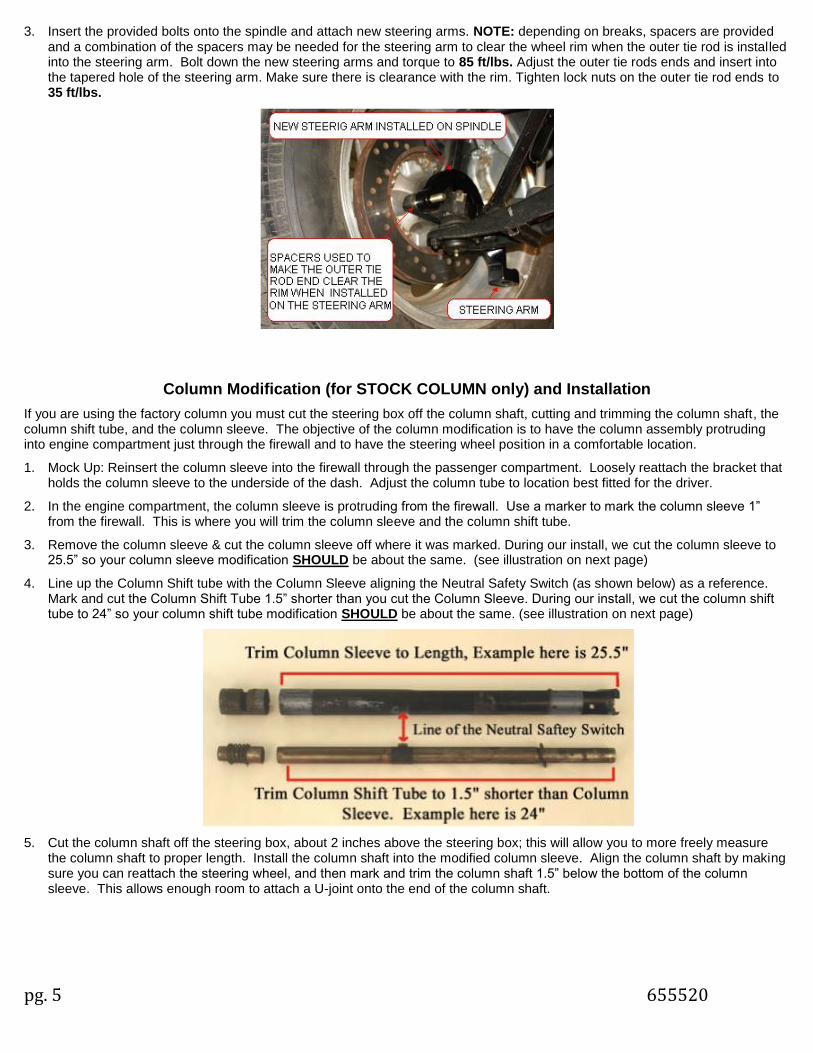
3. Insert the provided bolts onto the spindle and attach new steering arms. NOTE: depending on breaks, spacers are providedand a combination of the spacers may be needed for the steering arm to clear the wheel rim when the outer tie rod is installedinto the steering arm. Bolt down the new steering arms and torque to 85 ft/lbs. Adjust the outer tie rods ends and insert intothe tapered hole of the steering arm. Make sure there is clearance with the rim. Tighten lock nuts on the outer tie rod ends to35 ft/lbs.
Column Modification (for STOCK COLUMN only) and Installation
If you are using the factory column you must cut the steering box off the column shaft, cutting and trimming the column shaft, the column shift tube, and the column sleeve. The objective of the column modification is to have the column assembly protruding into engine compartment just through the firewall and to have the steering wheel position in a comfortable location.
1. Mock Up: Reinsert the column sleeve into the firewall through the passenger compartment. Loosely reattach the bracket thatholds the column sleeve to the underside of the dash. Adjust the column tube to location best fitted for the driver.
2. In the engine compartment, the column sleeve is protruding from the firewall. Use a marker to mark the column sleeve 1”from the firewall. This is where you will trim the column sleeve and the column shift tube.
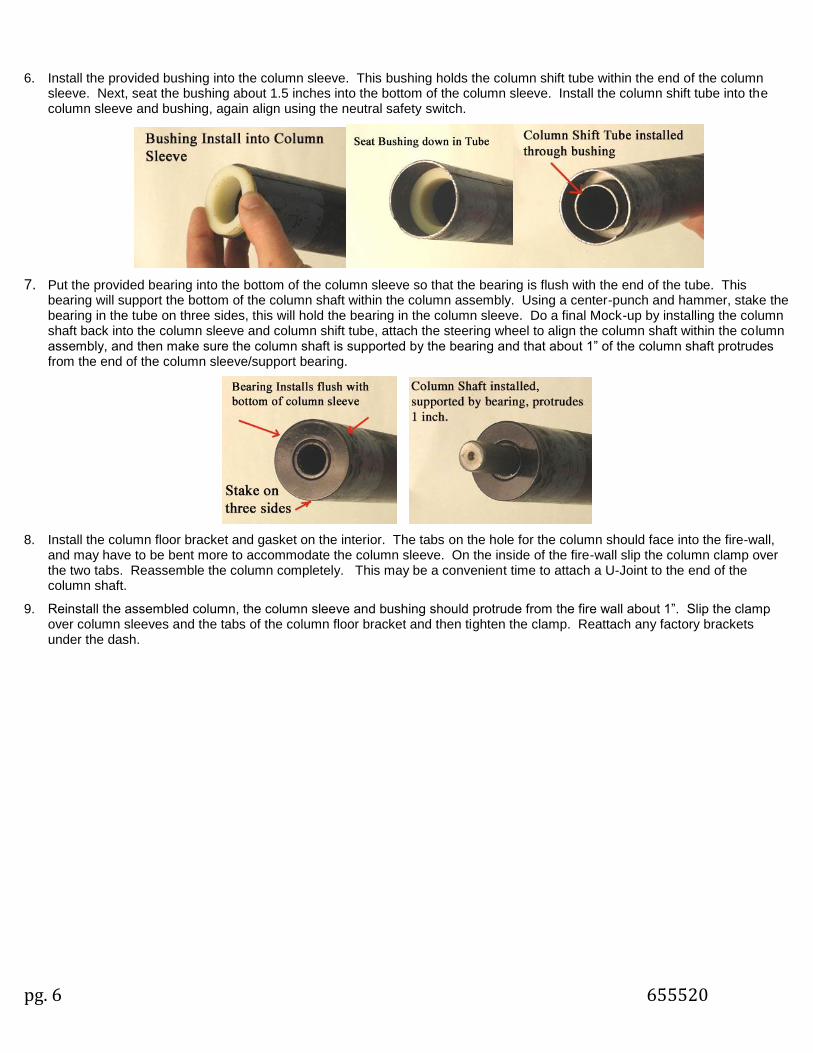
3. Remove the column sleeve & cut the column sleeve off where it was marked. During our install, we cut the column sleeve to25.5” so your column sleeve modification SHOULD be about the same. (see illustration on next page)
4. Line up the Column Shift tube with the Column Sleeve aligning the Neutral Safety Switch (as shown below) as a reference.Mark and cut the Column Shift Tube 1.5” shorter than you cut the Column Sleeve. During our install, we cut the column shifttube to 24” so your column shift tube modification SHOULD be about the same. (see illustration on next page)
5. Cut the column shaft off the steering box, about 2 inches above the steering box; this will allow you to more freely measurethe column shaft to proper length. Install the column shaft into the modified column sleeve. Align the column shaft by makingsure you can reattach the steering wheel, and then mark and trim the column shaft 1.5” below the bottom of the columnsleeve. This allows enough room to attach a U-joint onto the end of the column shaft.
pg. 6 655520
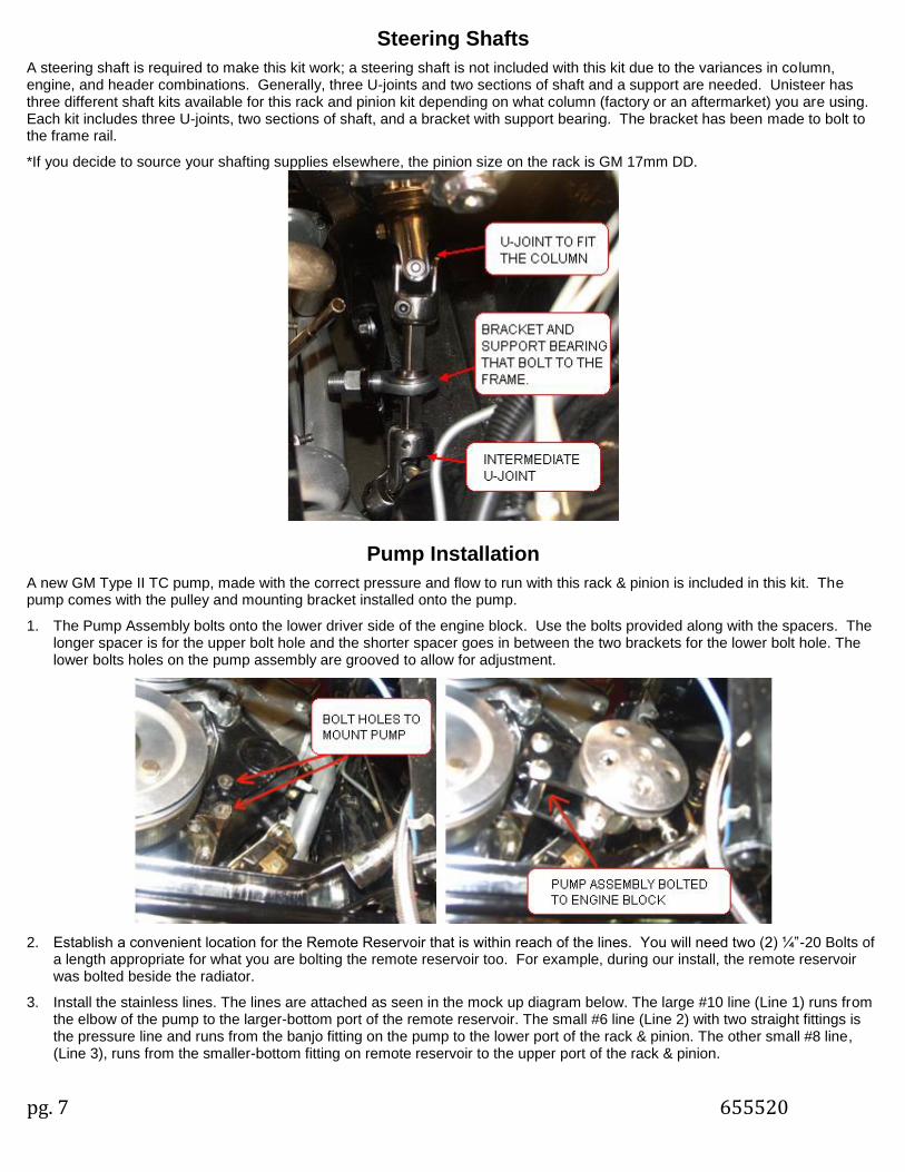
6. Install the provided bushing into the column sleeve. This bushing holds the column shift tube within the end of the column sleeve. Next, seat the bushing about 1.5 inches into the bottom of the column sleeve. Install the column shift tube into the column sleeve and bushing, again align using the neutral safety switch.
7. Put the provided bearing into the bottom of the column sleeve so that the bearing is flush with the end of the tube. This bearing will support the bottom of the column shaft within the column assembly. Using a center-punch and hammer, stake the bearing in the tube on three sides, this will hold the bearing in the column sleeve. Do a final Mock-up by installing the column shaft back into the column sleeve and column shift tube, attach the steering wheel to align the column shaft within the column assembly, and then make sure the column shaft is supported by the bearing and that about 1” of the column shaft protrudes from the end of the column sleeve/support bearing.
8. Install the column floor bracket and gasket on the interior. The tabs on the hole for the column should face into the fire-wall, and may have to be bent more to accommodate the column sleeve. On the inside of the fire-wall slip the column clamp over the two tabs. Reassemble the column completely. This may be a convenient time to attach a U-Joint to the end of the column shaft.
9. Reinstall the assembled column, the column sleeve and bushing should protrude from the fire wall about 1”. Slip the clamp over column sleeves and the tabs of the column floor bracket and then tighten the clamp. Reattach any factory brackets under the dash.
pg. 7 655520
Steering Shafts
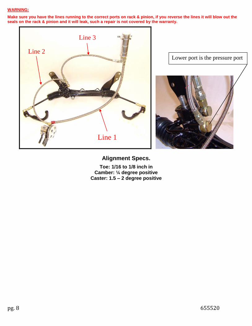
A steering shaft is required to make this kit work; a steering shaft is not included with this kit due to the variances in column, engine, and header combinations. Generally, three U-joints and two sections of shaft and a support are needed. Unisteer has three different shaft kits available for this rack and pinion kit depending on what column (factory or an aftermarket) you are using. Each kit includes three U-joints, two sections of shaft, and a bracket with support bearing. The bracket has been made to bolt to the frame rail.
*If you decide to source your shafting supplies elsewhere, the pinion size on the rack is GM 17mm DD.
Pump Installation
A new GM Type II TC pump, made with the correct pressure and flow to run with this rack & pinion is included in this kit. The pump comes with the pulley and mounting bracket installed onto the pump.
1. The Pump Assembly bolts onto the lower driver side of the engine block. Use the bolts provided along with the spacers. Thelonger spacer is for the upper bolt hole and the shorter spacer goes in between the two brackets for the lower bolt hole. Thelower bolts holes on the pump assembly are grooved to allow for adjustment.
2. Establish a convenient location for the Remote Reservoir that is within reach of the lines. You will need two (2) ¼”-20 Bolts ofa length appropriate for what you are bolting the remote reservoir too. For example, during our install, the remote reservoirwas bolted beside the radiator.
3. Install the stainless lines. The lines are attached as seen in the mock up diagram below. The large #10 line (Line 1) runs fromthe elbow of the pump to the larger-bottom port of the remote reservoir. The small #6 line (Line 2) with two straight fittings isthe pressure line and runs from the banjo fitting on the pump to the lower port of the rack & pinion. The other small #8 line,(Line 3), runs from the smaller-bottom fitting on remote reservoir to the upper port of the rack & pinion.
pg. 8 655520
WARNING:
Make sure you have the lines running to the correct ports on rack & pinion, if you reverse the lines it will blow out the seals on the rack & pinion and it will leak, such a repair is not covered by the warranty.
Alignment Specs.
Toe: 1/16 to 1/8 inch in Camber: ¼ degree positive
Caster: 1.5 – 2 degree positive
Line 1
Line 2
Line 3
Lower port is the pressure port