Embed Size (px)
Citation preview
2” Front Spacer KitChevy/GMC 1500 4WD Pickup | 2007-2017Chevy/GMC Tahoe/Suburban | 2007-2017
Rev. 122016
Part#: 021201
491 W. Garfield Ave., Coldwater, MI 49036 . Phone: 517-279-2135
Web/live chat: www.bds-suspension.com . E-mail: [email protected]
2 | 021201
Read And Understand All Instructions And Warnings Prior To Installation Of
System And Operation Of Vehicle.
BEFORE YOU STARTBDS Suspension Co. recommends this system be installed by a professional technician. In addition to these instructions, professional knowledge of disassembly/ reassembly procedures and post installation checks must be known.
FOR YOUR SAFETYCertain BDS Suspension products are intended to improve off-road per-formance. Modifying your vehicle for off-road use may result in the vehicle handling differently than a factory equipped vehicle. Extreme care must be used to prevent loss of control or vehicle rollover. Failure to drive your modified vehicle safely may result in serious injury or death. BDS Suspension Co. does not recommend the combined use of suspension lifts, body lifts, or other lifting devices. You should never operate your modified vehicle under the influence of alcohol or drugs. Always drive your modified vehicle at re-duced speeds to ensure your ability to control your vehicle under all driving conditions. Always wear your seat belt.
BEFORE INSTALLATIONSpecial literature required: OE Service Manual for model/year of vehicle. Refer to manual for proper disassembly/reassembly procedures of OE and related components.
Adhere to recommendations when replacement fasteners, retainers and keepers are called out in the OE manual.
Larger rim and tire combinations may increase leverage on suspension, steering, and related components. When selecting combinations larger than OE, consider the additional stress you could be inducing on the OE and related components.
Post suspension system vehicles may experience drive line vibrations. Angles may require tuning, slider on shaft may require replacement, shafts may need to be lengthened or trued, and U-joints may need to be replaced.
Secure and properly block vehicle prior to installation of BDS Suspension components. Always wear safety glasses when using power tools.
If installation is to be performed without a hoist, BDS Suspension Co. recom-mends rear alterations first.
Due to payload options and initial ride height variances, the amount of lift is a base figure. Final ride height dimensions may vary in accordance to original vehicle attitude. Always measure the attitude prior to beginning installation.
Your truck is about to be fitted with the best suspension system on the market today. That means you will be driving the baddest looking truck in the neighborhood, and you’ll have the warranty to ensure that it stays that way for years to come.
Thank you for choosing BDS Suspension!
BEFORE YOU DRIVECheck all fasteners for proper torque. Check to ensure for adequate clearance between all rotating, mobile, fixed, and heated members. Verify clearance between exhaust and brake lines, fuel lines, fuel tank, floor boards and wiring harness. Check steering gear for clearance. Test and inspect brake system.
Perform steering sweep to ensure front brake hoses have adequate slack and do not contact any rotating, mobile or heated members. Inspect rear brake hoses at full extension for adequate slack. Failure to perform hose check/ replacement may result in component failure. Longer replacement hoses, if needed can be purchased from a local parts supplier.
Perform head light check and adjustment.
Re-torque all fasteners after 500 miles. Always inspect fasteners and compo-nents during routine servicing.
FITMENT GUIDE
285/70R17 with stock wheel
021201 | 3
021201
Part # Qty Description
02155 2 Top Spacer
02157 2 Preload Spacer
02826 2 Weld on Steering Stop
740 1 Bolt Pack
6 7/16"-14 x 2-1/2" carriage bolt
6 7/16"-14 prevailing torque nut
6 12mm flat washer
TROUBLESHOOTING INFORMATION FOR YOUR VEHICLE1. Strut compressor required for installation.
MEASURE FIRSTMeasure from the center of the wheel up to the bottom edge of the wheel opening:
LF__________ RF__________
LR__________ RR__________
IMPORTANTA spring / strut compressor is required for this installation. Do NOT attempt to install this kit without one. Professional installation is highly recommended.
RECALL NOTICEGM issued a safety recall (#42190) for some 2016-17 vehicles built before 4/8/16 that were equipped with stamped steel upper control arms due to poor weld quality. BDS strongly recommends checking if your vehicle is included in the recall and having the fix performed before installing this suspension system.
FRONT DISASSEMBLY1. Park vehicle on clean, flat, and level surface.
2. Block rear wheels for safety. Raise front of vehicle and support frame rails with jack stands.
3. Remove front wheels, this will aid in installation.
4. Remove sway bar end links where they mount to the control arms. Retain all hardware, bushings, and sway bar links.
5. Work on one side of the vehicle at a time.
6. Support the lower control arm with a hydraulic jack, remove upper ball joint nut, reinstall nut by threading on by hand several turns.
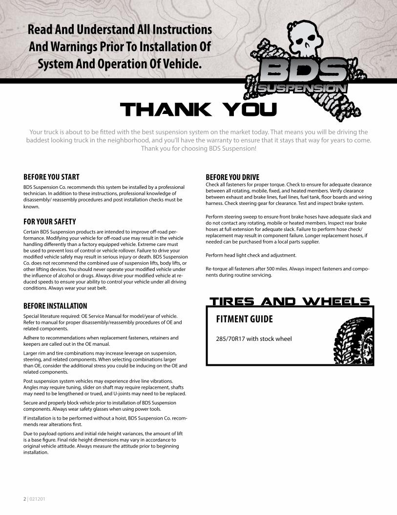
7. Strike the knuckle near the upper ball joint to dislodge it from the knuckle. (Fig 1)
High Quality Strut Compressor
4 | 021201
FIGURE 1
FIGURE 2
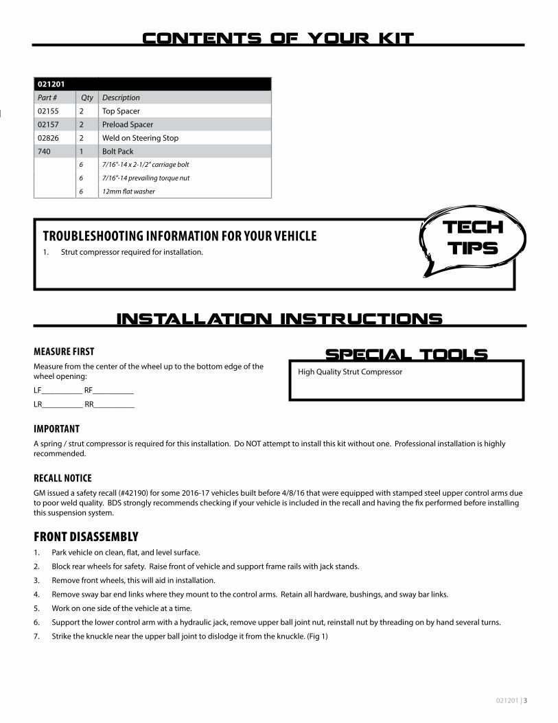
8. Remove 3 upper nuts holding top of strut to frame mount. (Fig 2). Do NOT remove center nut on strut.
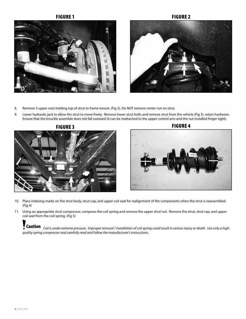
9. Lower hydraulic jack to allow the strut to move freely. Remove lower strut bolts and remove strut from the vehicle (Fig 3), retain hardware. Ensure that the knuckle assemble does not fall outward (it can be reattached to the upper control arm and the nut installed finger tight).
FIGURE 3
FIGURE 4
10. Place indexing marks on the strut body, strut cap, and upper coil seat for realignment of the components when the strut is reassembled. (Fig 4)
11. Using an appropriate strut compressor, compress the coil spring and remove the upper strut nut. Remove the strut, strut cap, and upper coil seat from the coil spring. (Fig 5)
Coil is under extreme pressure. Improper removal / installation of coil spring could result in serious injury or death. Use only a high-quality spring compressor and carefully read and follow the manufacturer’s instructions.
021201 | 5
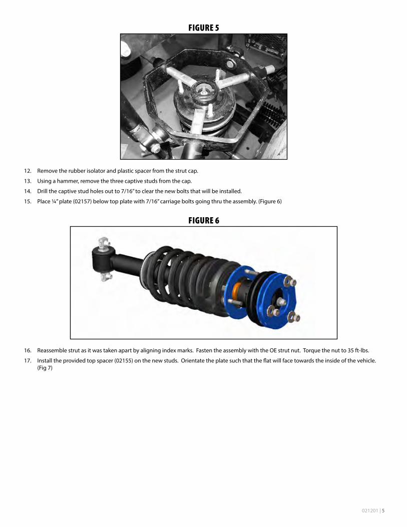
FIGURE 5
12. Remove the rubber isolator and plastic spacer from the strut cap.
13. Using a hammer, remove the three captive studs from the cap.
14. Drill the captive stud holes out to 7/16” to clear the new bolts that will be installed.
15. Place ¼” plate (02157) below top plate with 7/16” carriage bolts going thru the assembly. (Figure 6)
FIGURE 6
16. Reassemble strut as it was taken apart by aligning index marks. Fasten the assembly with the OE strut nut. Torque the nut to 35 ft-lbs.
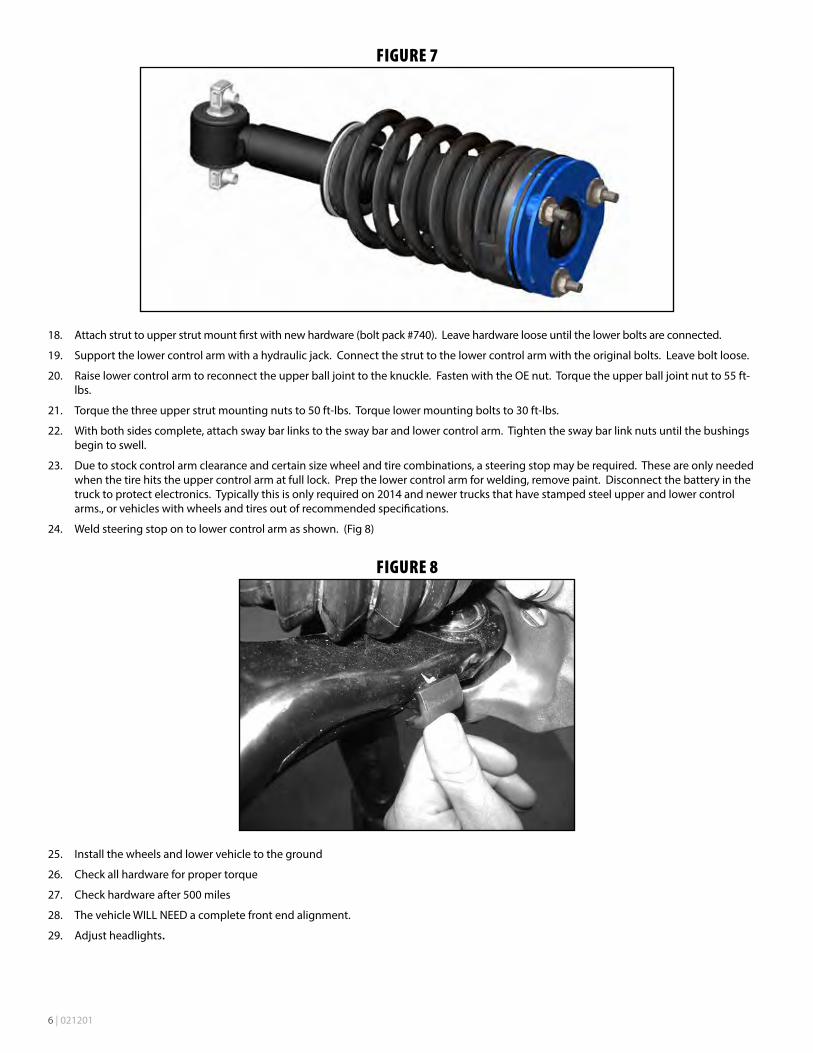
17. Install the provided top spacer (02155) on the new studs. Orientate the plate such that the flat will face towards the inside of the vehicle. (Fig 7)
6 | 021201
FIGURE 7
18. Attach strut to upper strut mount first with new hardware (bolt pack #740). Leave hardware loose until the lower bolts are connected.
19. Support the lower control arm with a hydraulic jack. Connect the strut to the lower control arm with the original bolts. Leave bolt loose.
20. Raise lower control arm to reconnect the upper ball joint to the knuckle. Fasten with the OE nut. Torque the upper ball joint nut to 55 ft-lbs.
21. Torque the three upper strut mounting nuts to 50 ft-lbs. Torque lower mounting bolts to 30 ft-lbs.
22. With both sides complete, attach sway bar links to the sway bar and lower control arm. Tighten the sway bar link nuts until the bushings begin to swell.
23. Due to stock control arm clearance and certain size wheel and tire combinations, a steering stop may be required. These are only needed when the tire hits the upper control arm at full lock. Prep the lower control arm for welding, remove paint. Disconnect the battery in the truck to protect electronics. Typically this is only required on 2014 and newer trucks that have stamped steel upper and lower control arms., or vehicles with wheels and tires out of recommended specifications.
24. Weld steering stop on to lower control arm as shown. (Fig 8)
FIGURE 8
25. Install the wheels and lower vehicle to the ground
26. Check all hardware for proper torque
27. Check hardware after 500 miles
28. The vehicle WILL NEED a complete front end alignment.
29. Adjust headlights.
021201 | 7
Thank you for choosing BDS Suspension.For questions, technical support and warranty issues relating to this BDS Suspension product, please contact your distributor/installer
before contacting BDS Suspension directly.