Embed Size (px)
Citation preview

NorthStar Technologies, Inc 791-1008-00 Rev. C 4 May 1999
Instruction Manual
SLIM Tach SL85Magnetoresistive Encoder
Designed for use in
0.625” to 3.000” (16mm to 76mm)Shaft Diameters
NorthStar Technologies, Inc.A Lake Shore Company575 McCorkle Blvd.Westerville, Ohio 43082Tel: (614) 818-1150Fax: (614) 891-6909E-mail: (sales) [email protected]
(service) [email protected]
*791-1008-00*
NorthStar SLIM Tach® SL85 Instruction Manual
2 NorthStar (614) 818-1150 4 May 1999
LIMITED WARRANTY
NorthStar Technologies, Inc. (henceforth NorthStar), the manufacturer, warrants this product for a period of twelve (12)months from the date of shipment. During the warranty period, under authorized return component parts to NorthStarfreight prepaid, the company will repair, or at its option replace, any part found to be defective in material or workmanship,without charge to the Owner for parts, service labor, or associated customary shipping cost. Replacement or repaired partswill be warranted for only the unused portion of the original warranty.
This warranty is limited to NorthStar products purchased and installed in the United States. This same protection willextend to any subsequent owner during the warranty period. It does not apply to damage caused by accident, misuse, fire,flood or acts of God, or from failure to properly install, operate, or maintain the product in accordance with the printedinstructions provided.
THIS WARRANTY IS IN LIEU OF ANY OTHER WARRANTIES, EXPRESSED OR IMPLIED, INCLUDINGMERCHANTABILITY OR FITNESS FOR A PARTICULAR PURPOSE, WHICH ARE EXPRESSLY EXCLUDED. THEOWNER AGREES THAT NORTHSTAR’S LIABILITY WITH RESPECT TO THIS PRODUCT SHALL BE SET FORTHIN THIS WARRANTY, AND INCIDENTAL OR CONSEQUENTIAL DAMAGES ARE EXPRESSLY EXCLUDED.
WARRANTY RETURN POLICY
If you experience any technical problems with NorthStar’s products, please contact our Technical Support Department at(614) 891-2245 from 8:00 A.M. to 5:00 P.M. Eastern Standard Time (EST), Monday through Friday or in writing to fax:(614) 891-6909, or email to [email protected]. Please be ready to provide your customer number, item description,serial number, invoice number, date of purchase, and the specifics of the problem.
A representative will attempt to solve your problem over the telephone by running a few diagnostics. If it is determined byour representative in conjunction with the Customer that the product requires to be returned to NorthStar’s factory forwarranty repair, a Return Goods Authorization (RGA) number will be issued. For control purposes, only those itemsidentified with an RGA number may be returned to NorthStar. Please make sure that the RGA number is clearly marked onthe shipping label. Packages missing an RGA number cannot be accepted by our Receiving Department and must bereturned to the sender freight COD. Ship returned products to NorthStar PRE-PAID and insured for its full value.
EXPRESS SERVICE IS OFFERED ON ALL WARRANTY REPAIRS WHERE AN RGA NUMBER HAS BEEN ISSUED.IF THE SAME WARRANTY PART THAT IS BEING RETURNED IS IN STOCK, NORTHSTAR WILLIMMEDIATELY SHIP OUT A NEW REPLACEMENT PART, INVOICE THE REPLACEMENT PART AND ISSUE ACREDIT INVOICE WHEN THE RGA NUMBER WARRANTY PART IS RECEIVED AT NORTHSTAR AND ISCONFIRMED TO BE A WARRANTY REPAIR. NORTHSTAR WILL EXPRESS SHIP THE PRODUCT PRE-PAID,USING THE SAME METHOD BY WHICH THE WARRANTY PART WAS SHIPPED TO NORTHSTAR, (i.e., IF THERGA WARRANTY PART WAS SHIPPED OVERNIGHT, NORTHSTAR WILL SHIP IN THE SAME MANNER.)
There is a 15% restocking fee on all items returned for credit to NorthStar. This includes all items in that are returned forexchange. All replacement parts must be purchased before they are sent out to the customer. If credit needs to be issued itwill be issued upon the return of the product if the unit is in good condition.
TRADEMARK ACKNOWLEDGMENT
Many of the designations used by manufacturers and sellers to distinguish their products are claimed as trademarks.Where those designations appear in this manual and NorthStar was aware of a trademark claim, the designations have beenprinted in initial capital letters and the or ® symbol used.
SLIM Tach® is a trademark of NorthStar Technologies, Inc.
Copyright © 1998 by NorthStar Technologies, Inc. All rights reserved. No portion of this manual may be reproduced, storedin a retrieval system, or transmitted, in any form or by any means, electronic, mechanical, photocopying, recording, orotherwise, without the express written permission of NorthStar.
NorthStar SLIM Tach® SL85 Instruction Manual
3 NorthStar (614) 818-1150 4 May 1999
Table of Contents
Chapter/Paragraph/Illustration Page
1 Introduction.................................................................................................................................. 4
1.0 Safety Summary............................................................................................................................. 4
1.1 General .......................................................................................................................................... 5
1.2 Description .................................................................................................................................... 5
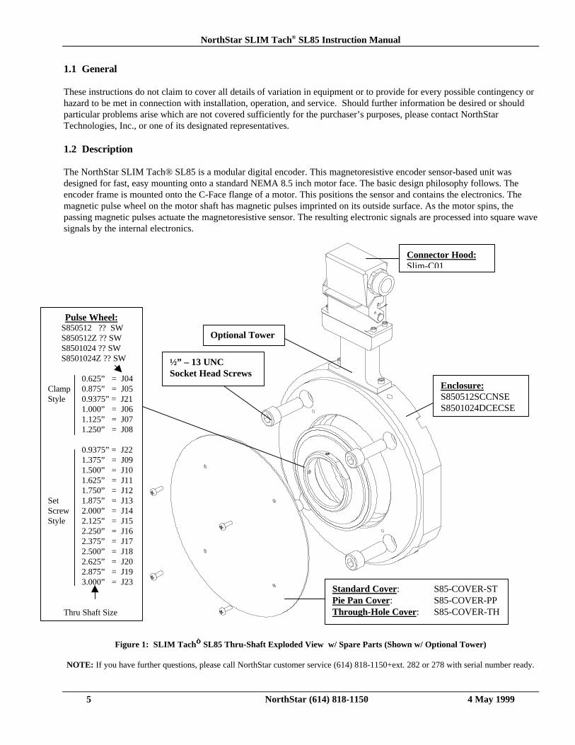
Figure 1: SLIM Tach SL85 Thru-Shaft Exploded View w/ Spare Parts ........................... 5
1.3 Specifications................................................................................................................................. 6
2 Installation.................................................................................................................................... 7
2.0 Inspection and Unpacking.............................................................................................................. 7
2.1 Motor Facing and Shaft for Thru-Shaft SL85 ................................................................................. 7
Figure 2: Typical 8.5 Inch Diameter Type C-Face Motor Thru-Shaft Application ............ 7
2.1.1 Encoder Frame Installation ............................................................................................................ 8
Figure 3: Typical Motor Mounting ................................................................................... 8
2.1.2 Thru-Shaft Pulse Wheel Installation............................................................................................... 9
Figure 4: Pulse Wheel Orientation ................................................................................... 9
Figure 5: SLIM Tach SL85 End-of-Shaft Exploded View................................................ 10
2.2 Motor Facing and Shaft for End-of-Shaft SL85 ............................................................................. 11
Figure 6: Typical 8.5 Inch Diameter Type C-Face Motor End-of-Shaft Application ......... 11
2.2.1 Encoder Frame Installation ............................................................................................................ 11
2.2.2 End-of-Shaft Pulse Wheel Installation ............................................................................................ 11
Figure 7: Pulse Wheel Assembly...................................................................................... 12
2.3 Electrical Installation ..................................................................................................................... 12
2.3.1 Quick Release Connector Hood Wiring .......................................................................................... 13
Figure 8: Sealed Industrial Latching Connector............................................................... 13
2.3.2 Returning Equipment to NorthStar................................................................................................. 14
Methods and apparatus disclosed and described herein have been developed solely on company funds of NorthStar Technologies, Inc. Nogovernment or other contractual support or relationship whatsoever has existed which in any way affects or mitigates proprietary rightsof NorthStar Technologies, Inc. in these developments. Methods and apparatus disclosed herein may be subject to U.S. Patents existingor applied for. NorthStar Technologies, Inc. reserves the right to add, improve, modify, or withdraw functions, design modifications, orproducts at any time without notice. NorthStar shall not be liable for errors contained herein or for incidental or consequential damagesin connection with furnishing, performance, or use of this material.
NorthStar SLIM Tach® SL85 Instruction Manual
4 NorthStar (614) 818-1150 4 May 1999
CHAPTER 1
INTRODUCTION1.0 Safety Summary
High current, voltage, and rotating parts can cause serious or fatal injury. The use of electric machinery, like all other usesof concentrated power and rotating equipment, may be hazardous. Installing, operating, and maintaining electric machineryshould be performed by qualified personnel, in accordance with applicable provisions of the National Electrical Code andsound local practices. Failure to comply with these precautions or with specific warnings elsewhere in this manual violatessafety standards of design, manufacture, and intended use of the instrument. NorthStar Technologies, Inc. assumes noliability for the customer's failure to comply with these requirements.
Rotating Machinery
Avoid contact with rotating parts. Avoid by-passing or rendering inoperative any safety guards or protection devices. Avoidextended exposure in close proximity to machinery with high noise levels. Use proper care and procedures in handling,lifting, installing, operating and maintaining the equipment.
Before Installation
Safe maintenance practices with qualified personnel is imperative. Before starting maintenance procedures, be positive that,(1) equipment connected to the shaft will not cause mechanical rotation, (2) main machine windings have beendisconnected and secured from all electrical power sources, and (3) all accessory devices associates with the work area havebeen de-energized. If high potential insulation test is required, follow procedures and precautions outlined in NEMAstandards MG-1.
Grounding
Improperly grounding the frame of the machine can cause serious or fatal injury to personnel. Grounding of the machineframe and structure should comply with the National Electrical Code and with sound local practices. Check wiring diagrambefore connecting power.
Do Not Operate In An Explosive Atmosphere
Do not operate the instrument in the presence of flammable gases or fumes. Operating any electrical instrument in such anenvironment constitutes a definite safety hazard.
Keep Away From Live Circuits
Operating personnel must not remove instrument covers. Component replacement and internal adjustments must be madeby qualified maintenance personnel. Do not replace components with power cable connected. To avoid injuries, alwaysdisconnect power and discharge circuits before touching them.
Do Not Substitute Parts Or Modify Instrument
Do not install substitute parts or perform any unauthorized modification to the instrument. Introducing additional hazards isdangerous. Return the instrument to an authorized NorthStar Technologies, Inc. representative for service and repair toensure that safety features are maintained.
Dangerous Procedure Cautions
A CAUTION heading precedes potentially dangerous procedures throughout this manual. Instructions in the warnings mustbe followed.
NorthStar SLIM Tach® SL85 Instruction Manual
5 NorthStar (614) 818-1150 4 May 1999
1.1 General
These instructions do not claim to cover all details of variation in equipment or to provide for every possible contingency orhazard to be met in connection with installation, operation, and service. Should further information be desired or shouldparticular problems arise which are not covered sufficiently for the purchaser’s purposes, please contact NorthStarTechnologies, Inc., or one of its designated representatives.
1.2 Description
The NorthStar SLIM Tach® SL85 is a modular digital encoder. This magnetoresistive encoder sensor-based unit wasdesigned for fast, easy mounting onto a standard NEMA 8.5 inch motor face. The basic design philosophy follows. Theencoder frame is mounted onto the C-Face flange of a motor. This positions the sensor and contains the electronics. Themagnetic pulse wheel on the motor shaft has magnetic pulses imprinted on its outside surface. As the motor spins, thepassing magnetic pulses actuate the magnetoresistive sensor. The resulting electronic signals are processed into square wavesignals by the internal electronics.
Figure 1: SLIM Tach SL85 Thru-Shaft Exploded View w/ Spare Parts (Shown w/ Optional Tower)
NOTE: If you have further questions, please call NorthStar customer service (614) 818-1150+ext. 282 or 278 with serial number ready.
Connector Hood:Slim-C01
Enclosure:S850512SCCNSES8501024DCECSE
Standard Cover: S85-COVER-STPie Pan Cover: S85-COVER-PPThrough-Hole Cover: S85-COVER-TH
Pulse Wheel: S850512 ?? SW S850512Z ?? SW S8501024 ?? SW S8501024Z ?? SW
0.625” = J04Clamp 0.875” = J05Style 0.9375” = J21
1.000” = J061.125” = J071.250” = J08
0.9375” = J221.375” = J091.500” = J101.625” = J111.750” = J12
Set 1.875” = J13Screw 2.000” = J14Style 2.125” = J15
2.250” = J162.375” = J172.500” = J182.625” = J202.875” = J193.000” = J23
Thru Shaft Size
Optional Tower
½” – 13 UNCSocket Head Screws
NorthStar SLIM Tach® SL85 Instruction Manual
6 NorthStar (614) 818-1150 4 May 1999
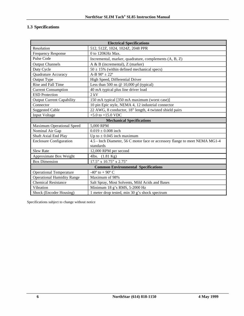
1.3 Specifications
Electrical SpecificationsResolution 512, 512Z, 1024, 1024Z, 2048 PPRFrequency Response 0 to 120KHz Max.Pulse Code Incremental, marker, quadrature, complements (A, B, Z)Output Channels A & B (incremental), Z (marker)Duty Cycle 50 ± 15% (within defined mechanical specs)Quadrature Accuracy A-B 90º ± 22ºOutput Type High Speed, Differential DriverRise and Fall Time Less than 500 ns @ 10,000 pf (typical)Current Consumption 40 mA typical plus line driver loadESD Protection 2 kVOutput Current Capability 150 mA typical [350 mA maximum (worst case)]Connector 10 pin Epic style, NEMA 4, 12 industrial connectorSuggested Cable 22 AWG, 8 conductor, 18” length, 4 twisted shield pairsInput Voltage +5.0 to +15.0 VDC
Mechanical SpecificationsMaximum Operational Speed 5,000 RPMNominal Air Gap 0.019 ± 0.008 inchShaft Axial End Play Up to ± 0.045 inch maximumEnclosure Configuration 4.5 - Inch Diameter, 56 C motor face or accessory flange to meet NEMA MG1-4
standardsSlew Rate 12,000 RPM per secondApproximate Box Weight 4lbs. (1.81 Kg)Box Dimension 17.5” x 10.75” x 2.75”
Common Environmental SpecificationsOperational Temperature -40º to + 90º COperational Humidity Range Maximum of 98%Chemical Resistance Salt Spray, Most Solvents, Mild Acids and BasesVibration Minimum 18 g’s RMS, 5-2000 HzShock (Encoder Housing) 1 meter drop tested, min 30 g’s shock spectrum
Specifications subject to change without notice
NorthStar SLIM Tach® SL85 Instruction Manual
7 NorthStar (614) 818-1150 4 May 1999
CHAPTER 2
INSTALLATION
2.0 Inspection and Unpacking
Inspect shipping container for external damage. All claims for damage (apparent or concealed) or partial loss of shipmentmust be made in writing to NorthStar within (5) days from receipt of goods. If damage or loss is apparent, please notify theshipping agent immediately.
Open shipping container and locate the packing list. The packing list is included to verify that all components, accessories,and manual were received. Please use the packing list to check off each item as the unit is unpacked. Inspect for damage.NorthStar recommends that the shipping container be retained for future shipping, storage, or return to factory purposes.
If any equipment was damaged in transit, be sure to file proper claims promptly with the carrier and insurance company.Please advise NorthStar Technologies of such filing. In case of parts shortages, advise NorthStar immediately. NorthStarcannot be responsible for any missing parts unless notified within 60 days of shipment. The standard NorthStarTechnologies, Inc. warranty is included on page 2 of this manual.
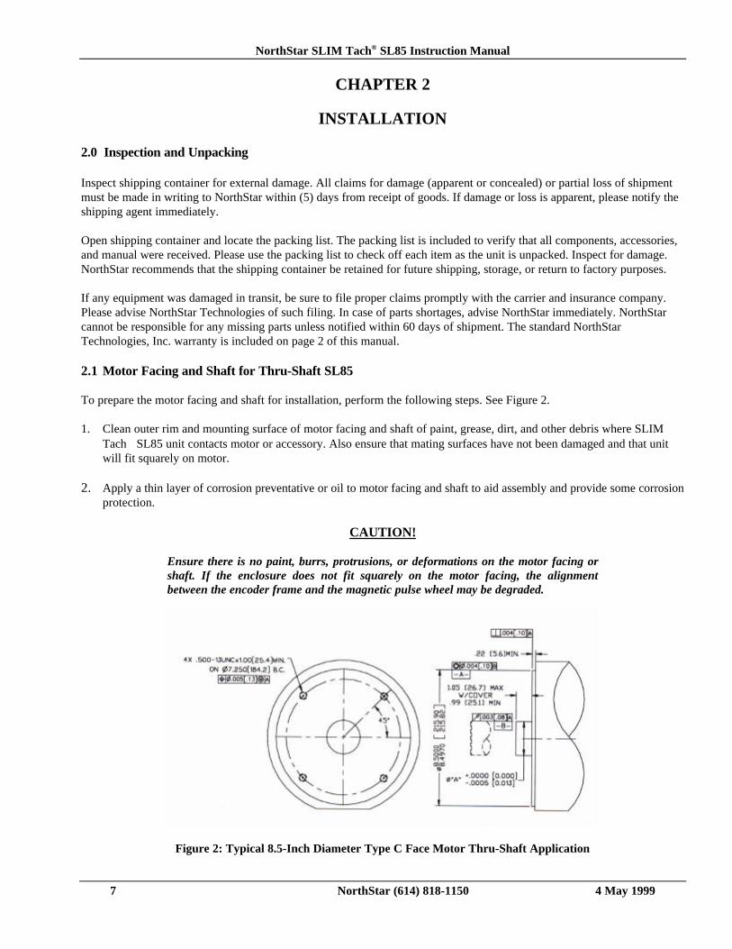
2.1 Motor Facing and Shaft for Thru-Shaft SL85
To prepare the motor facing and shaft for installation, perform the following steps. See Figure 2.
1. Clean outer rim and mounting surface of motor facing and shaft of paint, grease, dirt, and other debris where SLIMTach SL85 unit contacts motor or accessory. Also ensure that mating surfaces have not been damaged and that unitwill fit squarely on motor.
2. Apply a thin layer of corrosion preventative or oil to motor facing and shaft to aid assembly and provide some corrosionprotection.
CAUTION!
Ensure there is no paint, burrs, protrusions, or deformations on the motor facing orshaft. If the enclosure does not fit squarely on the motor facing, the alignmentbetween the encoder frame and the magnetic pulse wheel may be degraded.
Figure 2: Typical 8.5-Inch Diameter Type C Face Motor Thru-Shaft Application
NorthStar SLIM Tach® SL85 Instruction Manual
8 NorthStar (614) 818-1150 4 May 1999
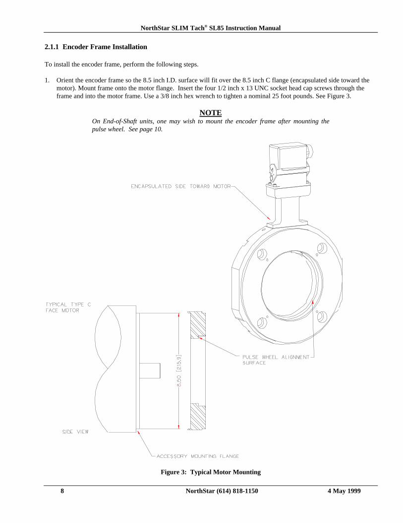
2.1.1 Encoder Frame Installation
To install the encoder frame, perform the following steps.
1. Orient the encoder frame so the 8.5 inch I.D. surface will fit over the 8.5 inch C flange (encapsulated side toward themotor). Mount frame onto the motor flange. Insert the four 1/2 inch x 13 UNC socket head cap screws through theframe and into the motor frame. Use a 3/8 inch hex wrench to tighten a nominal 25 foot pounds. See Figure 3.
NOTEOn End-of-Shaft units, one may wish to mount the encoder frame after mounting thepulse wheel. See page 10.
Figure 3: Typical Motor Mounting
NorthStar SLIM Tach® SL85 Instruction Manual
9 NorthStar (614) 818-1150 4 May 1999
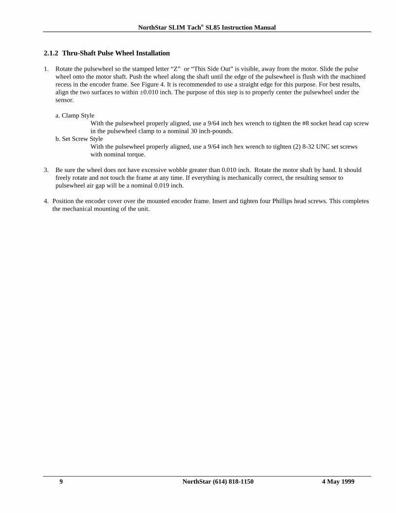
2.1.2 Thru-Shaft Pulse Wheel Installation
1. Rotate the pulsewheel so the stamped letter “Z” or “This Side Out” is visible, away from the motor. Slide the pulsewheel onto the motor shaft. Push the wheel along the shaft until the edge of the pulsewheel is flush with the machinedrecess in the encoder frame. See Figure 4. It is recommended to use a straight edge for this purpose. For best results,align the two surfaces to within ±0.010 inch. The purpose of this step is to properly center the pulsewheel under thesensor.
a. Clamp StyleWith the pulsewheel properly aligned, use a 9/64 inch hex wrench to tighten the #8 socket head cap screwin the pulsewheel clamp to a nominal 30 inch-pounds.
b. Set Screw StyleWith the pulsewheel properly aligned, use a 9/64 inch hex wrench to tighten (2) 8-32 UNC set screwswith nominal torque.
3. Be sure the wheel does not have excessive wobble greater than 0.010 inch. Rotate the motor shaft by hand. It shouldfreely rotate and not touch the frame at any time. If everything is mechanically correct, the resulting sensor topulsewheel air gap will be a nominal 0.019 inch.
4. Position the encoder cover over the mounted encoder frame. Insert and tighten four Phillips head screws. This completesthe mechanical mounting of the unit.
NorthStar SLIM Tach® SL85 Instruction Manual
10 NorthStar (614) 818-1150 4 May 1999
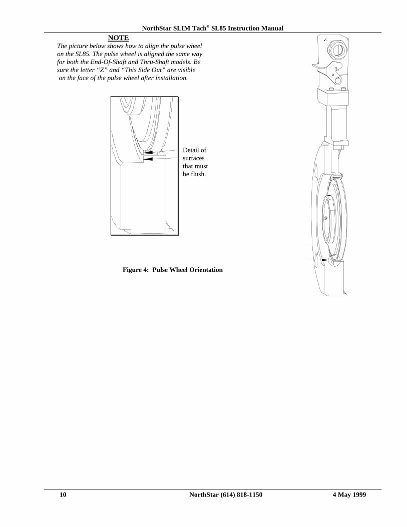
NOTEThe picture below shows how to align the pulse wheelon the SL85. The pulse wheel is aligned the same way
for both the End-Of-Shaft and Thru-Shaft models. Besure the letter “Z” and “This Side Out” are visible on the face of the pulse wheel after installation.
Figure 4: Pulse Wheel Orientation
Detail ofsurfacesthat mustbe flush.
NorthStar SLIM Tach® SL85 Instruction Manual
11 NorthStar (614) 818-1150 4 May 1999
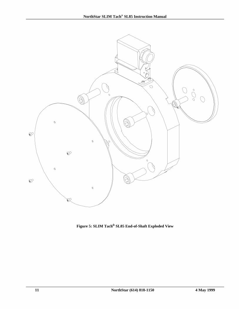
Figure 5: SLIM Tach SL85 End-of-Shaft Exploded View
NorthStar SLIM Tach® SL85 Instruction Manual
12 NorthStar (614) 818-1150 4 May 1999
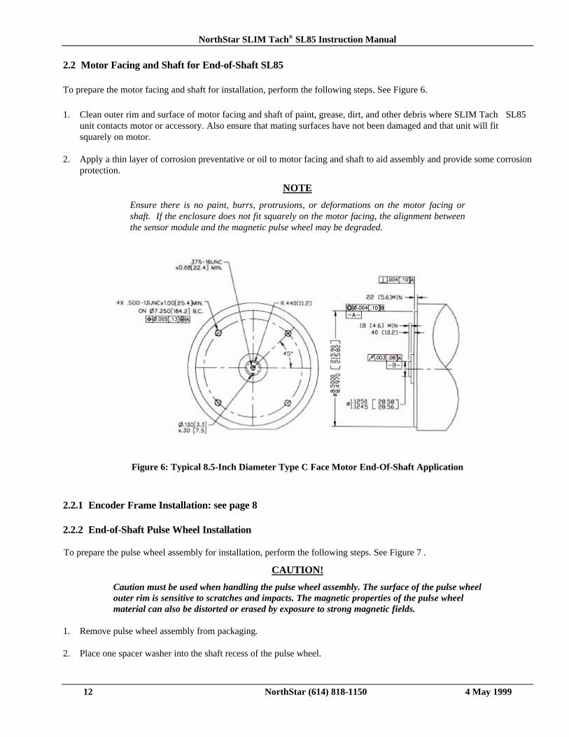
2.2 Motor Facing and Shaft for End-of-Shaft SL85
To prepare the motor facing and shaft for installation, perform the following steps. See Figure 6.
1. Clean outer rim and surface of motor facing and shaft of paint, grease, dirt, and other debris where SLIM Tach SL85unit contacts motor or accessory. Also ensure that mating surfaces have not been damaged and that unit will fitsquarely on motor.
2. Apply a thin layer of corrosion preventative or oil to motor facing and shaft to aid assembly and provide some corrosionprotection.
NOTE
Ensure there is no paint, burrs, protrusions, or deformations on the motor facing orshaft. If the enclosure does not fit squarely on the motor facing, the alignment betweenthe sensor module and the magnetic pulse wheel may be degraded.
Figure 6: Typical 8.5-Inch Diameter Type C Face Motor End-Of-Shaft Application
2.2.1 Encoder Frame Installation: see page 8
2.2.2 End-of-Shaft Pulse Wheel Installation
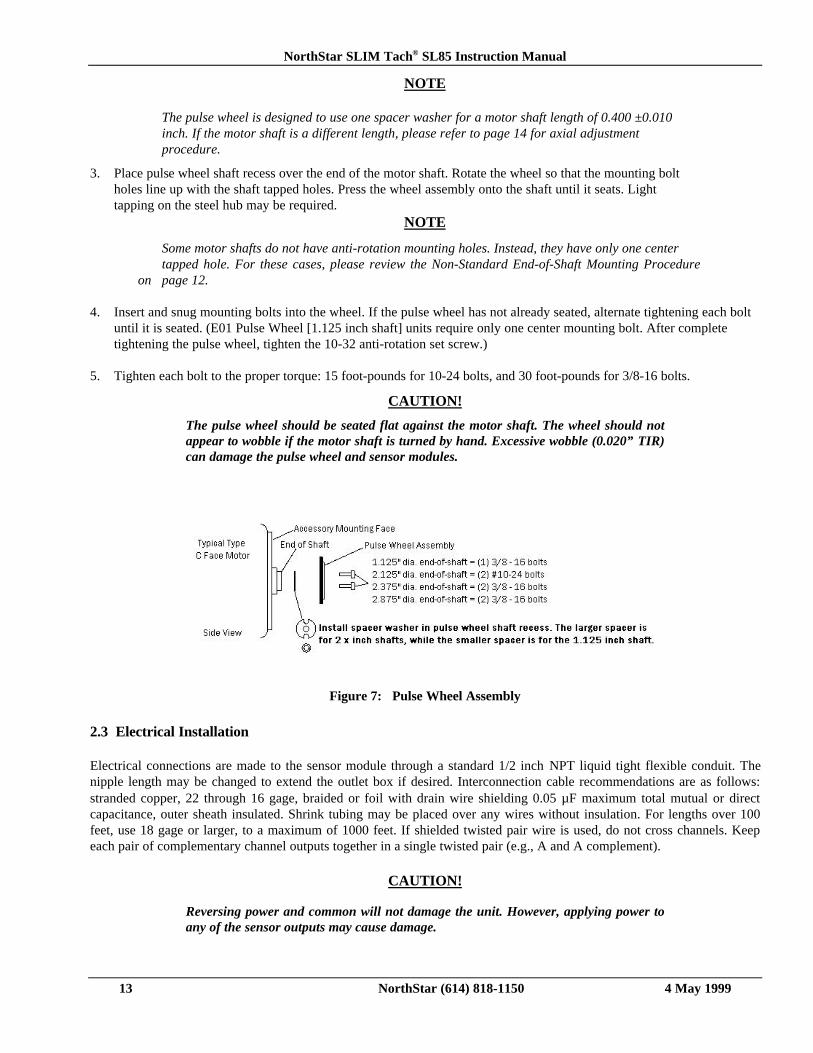
To prepare the pulse wheel assembly for installation, perform the following steps. See Figure 7 .
CAUTION!
Caution must be used when handling the pulse wheel assembly. The surface of the pulse wheelouter rim is sensitive to scratches and impacts. The magnetic properties of the pulse wheelmaterial can also be distorted or erased by exposure to strong magnetic fields.
1. Remove pulse wheel assembly from packaging.
2. Place one spacer washer into the shaft recess of the pulse wheel.
NorthStar SLIM Tach® SL85 Instruction Manual
13 NorthStar (614) 818-1150 4 May 1999
NOTE
The pulse wheel is designed to use one spacer washer for a motor shaft length of 0.400 ±0.010inch. If the motor shaft is a different length, please refer to page 14 for axial adjustmentprocedure.
3. Place pulse wheel shaft recess over the end of the motor shaft. Rotate the wheel so that the mounting boltholes line up with the shaft tapped holes. Press the wheel assembly onto the shaft until it seats. Lighttapping on the steel hub may be required.
NOTE
Some motor shafts do not have anti-rotation mounting holes. Instead, they have only one center tapped hole. For these cases, please review the Non-Standard End-of-Shaft Mounting Procedure
on page 12.
4. Insert and snug mounting bolts into the wheel. If the pulse wheel has not already seated, alternate tightening each boltuntil it is seated. (E01 Pulse Wheel [1.125 inch shaft] units require only one center mounting bolt. After completetightening the pulse wheel, tighten the 10-32 anti-rotation set screw.)
5. Tighten each bolt to the proper torque: 15 foot-pounds for 10-24 bolts, and 30 foot-pounds for 3/8-16 bolts.
CAUTION!
The pulse wheel should be seated flat against the motor shaft. The wheel should notappear to wobble if the motor shaft is turned by hand. Excessive wobble (0.020” TIR)can damage the pulse wheel and sensor modules.
Figure 7: Pulse Wheel Assembly
2.3 Electrical Installation
Electrical connections are made to the sensor module through a standard 1/2 inch NPT liquid tight flexible conduit. Thenipple length may be changed to extend the outlet box if desired. Interconnection cable recommendations are as follows:stranded copper, 22 through 16 gage, braided or foil with drain wire shielding 0.05 µF maximum total mutual or directcapacitance, outer sheath insulated. Shrink tubing may be placed over any wires without insulation. For lengths over 100feet, use 18 gage or larger, to a maximum of 1000 feet. If shielded twisted pair wire is used, do not cross channels. Keepeach pair of complementary channel outputs together in a single twisted pair (e.g., A and A complement).
CAUTION!
Reversing power and common will not damage the unit. However, applying power toany of the sensor outputs may cause damage.
NorthStar SLIM Tach® SL85 Instruction Manual
14 NorthStar (614) 818-1150 4 May 1999
Table 1. Signal Coding Table
Signal Connector Pin Pigtail Cable MS 3102E18-IT#
CommonBAZ *No ConnectionVcc (5-15 VDC)/B/A/Z *Shield
12345678910
BlackGreenBlueViolet-----RedYellowGrayOrangeBraid
FBACEDIHJG
* Applies only to units with index pulse capability.# Pinouts are for the sensors with the MS 3102E18IT connector
NOTEThe shield in the sensor module is isolated from the frame of the encoder. For maximumnoise immunity, the shield wire or pin should be connected to the shield of the cable andthat of the drive or other receiving device.
2.3.1 Quick Release Connector Hood Wiring
To install the Quick Release Connector, perform the following steps.
1. Remove the four screws from the mating connector housing that hold the terminal block in place. Remove terminalblock from housing.
2. Insert wiring through liquid tight flexible seal and mating connector housing. Leave enough wire exposed tocomfortably reach the terminal block. Wire to terminal block according to wire code in Table 1. A similar wiring list isattached to enclosure.
NOTEThere are two orientations of the connector hood. The terminal block can be insertedeither way so the connector hood points up or down. Choose the direction best for yourapplication.
4. Tighten Liquid Tight fitting on housing. OPTIONAL: In some hostile environments, seal between connector body and Sensor Module can be improved by smearing a sealant (silicone grease, etc.) on the neoprene seal of the connector.
5. Mate connector into place on sensor mount and snap the two latches into place. If only one sensor is being installed, ensure cover plate is installed over other sensor hole.
Figure 8: Sealed Industrial Latching Connector
NorthStar SLIM Tach® SL85 Instruction Manual
15 NorthStar (614) 818-1150 4 May 1999
2.3.2 Returning Equipment to NorthStar
If it is necessary to return the unit for repair or replacement, a Return Goods Authorization (RGA) number must be obtainedfrom a factory representative before returning the equipment to our service department. When returning an instrument forservice, the following information must be provided before NorthStar can attempt any repair.
1. Instrument model and serial number
2. User’s name, company, address, and phone number
3. Malfunction symptoms
4. Description of system
5. Returned Goods Authorization number
Consult the factory for shipping instructions.

NorthStar SLIM Tach® SL85 Instruction Manual
16 NorthStar (614) 818-1150 4 May 1999
NorthStar Technologies, Inc.A Lake Shore Company575 McCorkle Blvd.Westerville, Ohio 43082Tel: (614) 818-1150Fax: (614) 891-6909E-mail: (sales) [email protected]
(service) [email protected]